PI6C20800AE中文资料
可编程数字控制器 M A P 6 使用手册
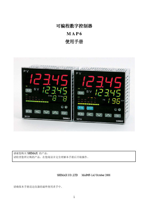
可编程数字控制器M A P 6使用手册感谢您购买SHIMAX 的产品。
请检查您所订购的产品。
在您阅读并完全理解本手册后开始操作。
SHIMAX CO.,LTD MAP6F-1AJ October 2008 请确保本手册送达仪器的最终使用者手中。
目录1.前言・・・・・・・・・・・・・・・・・・・・・・・・・・・・・・・・・・・・・・・・・・・・・・・・・・・・・・・・・・・・・・・・・・・・・・・・・・・・・・・・・3 2.安全措施・・・・・・・・・・・・・・・・・・・・・・・・・・・・・・・・・・・・・・・・・・・・・・・・・・・・・・・・・・・・・・・・・・・・・・・・・・・・・3 3.简介・・・・・・・・・・・・・・・・・・・・・・・・・・・・・・・・・・・・・・・・・・・・・・・・・・・・・・・・・・・・・・・・・・・・・・・・・・・・・・・・・3 3-1使用前检查・・・・・・・・・・・・・・・・・・・・・・・・・・・・・・・・・・・・・・・・・・・・・・・・・・・・・・・・・・・・・・・・・・・・・・4 3-2使用注意事项・・・・・・・・・・・・・・・・・・・・・・・・・・・・・・・・・・・・・・・・・・・・・・・・・・・・・・・・・・・・・・・・・・・・・4 3-3订货信息・・・・・・・・・・・・・・・・・・・・・・・・・・・・・・・・・・・・・・・・・・・・・・・・・・・・・・・・・・・・・・・・・・・・・・・・・5 4.安装和接线・・・・・・・・・・・・・・・・・・・・・・・・・・・・・・・・・・・・・・・・・・・・・・・・・・・・・・・・・・・・・・・・・・・・・・・・・・・6 4-1安装场地・・・・・・・・・・・・・・・・・・・・・・・・・・・・・・・・・・・・・・・・・・・・・・・・・・・・・・・・・・・・・・・・・・・・・・・・・6 4-2固定・・・・・・・・・・・・・・・・・・・・・・・・・・・・・・・・・・・・・・・・・・・・・・・・・・・・・・・・・・・・・・・・・・・・・・・・・・・・・6 4-3外形尺寸和面板开口・・・・・・・・・・・・・・・・・・・・・・・・・・・・・・・・・・・・・・・・・・・・・・・・・・・・・・・・・・・・・・・7 4-4接线・・・・・・・・・・・・・・・・・・・・・・・・・・・・・・・・・・・・・・・・・・・・・・・・・・・・・・・・・・・・・・・・・・・・・・・・・・・・・8 4-5端子排列与接线图・・・・・・・・・・・・・・・・・・・・・・・・・・・・・・・・・・・・・・・・・・・・・・・・・・・・・・・・・・・・・・・・・9 5.前面板介绍・・・・・・・・・・・・・・・・・・・・・・・・・・・・・・・・・・・・・・・・・・・・・・・・・・・・・・・・・・・・・・・・・・・・・・・・・・11 5-1前面板名称・・・・・・・・・・・・・・・・・・・・・・・・・・・・・・・・・・・・・・・・・・・・・・・・・・・・・・・・・・・・・・・・・・・・・・11 5-2前面板各部分说明・・・・・・・・・・・・・・・・・・・・・・・・・・・・・・・・・・・・・・・・・・・・・・・・・・・・・・・・・・・・・・・・12 6.窗口说明・・・・・・・・・・・・・・・・・・・・・・・・・・・・・・・・・・・・・・・・・・・・・・・・・・・・・・・・・・・・・・・・・・・・・・・・・・・・15 6-1如何移动到其他窗口・・・・・・・・・・・・・・・・・・・・・・・・・・・・・・・・・・・・・・・・・・・・・・・・・・・・・・・・・・・・・・15 6-2设置方法・・・・・・・・・・・・・・・・・・・・・・・・・・・・・・・・・・・・・・・・・・・・・・・・・・・・・・・・・・・・・・・・・・・・・・・・16 6-3接通电源和初始化窗口显示・・・・・・・・・・・・・・・・・・・・・・・・・・・・・・・・・・・・・・・・・・・・・・・・・・・・・・・・16 6-4各窗口的说明・・・・・・・・・・・・・・・・・・・・・・・・・・・・・・・・・・・・・・・・・・・・・・・・・・・・・・・・・・・・・・・・・・・・17 (1)基本窗口群・・・・・・・・・・・・・・・・・・・・・・・・・・・・・・・・・・・・・・・・・・・・・・・・・・・・・・・・・・・・・・・・・・・・・17 (2)PROG(程序控制)参数窗口群・・・・・・・・・・・・・・・・・・・・・・・・・・・・・・・・・・・・・・・・・・・・・・・・・・・・・25 (3)FIX(固定值控制)参数窗口群・・・・・・・・・・・・・・・・・・・・・・・・・・・・・・・・・・・・・・・・・・・・・・・・・・・・・34 (4)参数窗口群・・・・・・・・・・・・・・・・・・・・・・・・・・・・・・・・・・・・・・・・・・・・・・・・・・・・・・・・・・・・・・・・・・・・・・35 (5)1-0按键锁定窗口群・・・・・・・・・・・・・・・・・・・・・・・・・・・・・・・・・・・・・・・・・・・・・・・・・・・・・・・・・・・・・・35 (6)2-0输入参数窗口群・・・・・・・・・・・・・・・・・・・・・・・・・・・・・・・・・・・・・・・・・・・・・・・・・・・・・・・・・・・・・・38 (7)3-0输出1的PID参数窗口群・・・・・・・・・・・・・・・・・・・・・・・・・・・・・・・・・・・・・・・・・・・・・・・・・・・・・・41 (8)4-0 输出2的PID参数窗口群・・・・・・・・・・・・・・・・・・・・・・・・・・・・・・・・・・・・・・・・・・・・・・・・・・・・・・47 (9)5-0区域PID窗口群・・・・・・・・・・・・・・・・・・・・・・・・・・・・・・・・・・・・・・・・・・・・・・・・・・・・・・・・・・・・・・50 (10)6-0 EV报警窗口群・・・・・・・・・・・・・・・・・・・・・・・・・・・・・・・・・・・・・・・・・・・・・・・・・・・・・・・・・・・・・・52 (11)7-0 DO报警窗口群・・・・・・・・・・・・・・・・・・・・・・・・・・・・・・・・・・・・・・・・・・・・・・・・・・・・・・・・・・・・・・54 (12)8-0 DI输入设定窗口・・・・・・・・・・・・・・・・・・・・・・・・・・・・・・・・・・・・・・・・・・・・・・・・・・・・・・・・・・・・・58 (13)9-0模拟发送窗口群・・・・・・・・・・・・・・・・・・・・・・・・・・・・・・・・・・・・・・・・・・・・・・・・・・・・・・・・・・・・・58 (14)10-0模拟输入窗口群・・・・・・・・・・・・・・・・・・・・・・・・・・・・・・・・・・・・・・・・・・・・・・・・・・・・・・・・・・・・60 (15)11-0 CT报警断线报警窗口群・・・・・・・・・・・・・・・・・・・・・・・・・・・・・・・・・・・・・・・・・・・・・・・・・・・・・63 (16)12-0通讯参数窗口群・・・・・・・・・・・・・・・・・・・・・・・・・・・・・・・・・・・・・・・・・・・・・・・・・・・・・・・・・・・・64 (17)13-0伺服设置窗口群・・・・・・・・・・・・・・・・・・・・・・・・・・・・・・・・・・・・・・・・・・・・・・・・・・・・・・・・・・・・64 (18)14-0 PV/SV多点补偿参数窗口群・・・・・・・・・・・・・・・・・・・・・・・・・・・・・・・・・・・・・・・・・・・・・・・・・・68 7.功能的补充说明・・・・・・・・・・・・・・・・・・・・・・・・・・・・・・・・・・・・・・・・・・・・・・・・・・・・・・・・・・・・・・・・・・・・・・73 7-1自动返回功能・・・・・・・・・・・・・・・・・・・・・・・・・・・・・・・・・・・・・・・・・・・・・・・・・・・・・・・・・・・・・・・・・・・・72 7-2输出软启动功能・・・・・・・・・・・・・・・・・・・・・・・・・・・・・・・・・・・・・・・・・・・・・・・・・・・・・・・・・・・・・・・・・・72 7-3事件报警方式・・・・・・・・・・・・・・・・・・・・・・・・・・・・・・・・・・・・・・・・・・・・・・・・・・・・・・・・・・・・・・・・・・・・72 7-4 AT(自整定)・・・・・・・・・・・・・・・・・・・・・・・・・・・・・・・・・・・・・・・・・・・・・・・・・・・・・・・・・・・・・・・・・・・・72 8.故障排除・・・・・・・・・・・・・・・・・・・・・・・・・・・・・・・・・・・・・・・・・・・・・・・・・・・・・・・・・・・・・・・・・・・・・・・・・・・・73 8-1原因和主要故障的处理・・・・・・・・・・・・・・・・・・・・・・・・・・・・・・・・・・・・・・・・・・・・・・・・・・・・・・・・・・・・73 8-2原因和故障显示的处理・・・・・・・・・・・・・・・・・・・・・・・・・・・・・・・・・・・・・・・・・・・・・・・・・・・・・・・・・・・・73 9.技术规格・・・・・・・・・・・・・・・・・・・・・・・・・・・・・・・・・・・・・・・・・・・・・・・・・・・・・・・・・・・・・・・・・・・・・・・・・・・・741 前言本手册对MAP6的接线、安装、操作和日常维护具有重要意义。
ISCOM6800(A) 光接入局端汇聚设备 产品描述(Rel_01)
《ISCOM6800 光接入局端汇聚设备 安装指南》
《ISCOM6800 光接入局端汇聚设备 快速安装指南》
内容简介
主要针对产品支持各类业务,从业务简介、 缺省配置、业务配置方法、配置举例等方面 介绍了各类业务的配置方法和过程。包括: 基础配置、EPON 业务配置、组播业务配置、 VoIP 业务配置、CATV 业务配置、TDMoP 业 务配置、MAC 地址表配置、VLAN 配置、生 成树配置、路由功能配置、DHCP 配置、QoS 配置、系统安全配置、链路安全配置、系统 管理配置。
主要详细介绍了产品安装前的注意事项、安 装方法和安装后的检查。包括:安全说明、 安装说明、安装机箱、安装风扇和导风框、 安装单板、布放线缆、硬件安装检查、上电 检查、设备初始化、安装参考。
主要介绍了产品开箱后的主要安装过程。包 括:安装工具、注意事项、安装场景、安装 条件以及安装步骤。
约定
符号约定
在本文中可能出现下列标志,它们所代表的含义如下。
通用格式约定
格式 宋体 黑体 楷体 Lucida Console 格式
说明 正文采用宋体表示。 一级标题、二级标题、三级标题、Block 采用黑体表示。 警告、提示等内容用楷体表示。 Lucida Console 格式表示屏幕输出信息。此外,屏幕 输出信息中夹杂的用户输入信息采用加粗字体表示。
修订记录
1.1 产品简介......................................................................................................................................................1-1 1.2 产品特点......................................................................................................................................................1-2
普传(POWTRAN)变频器PI8600变频器使用说明书
前言感谢您使用普传PI8600系列变频器。
本产品是普传科技经多年经验积累而设计的适合在各种产业机械的变频调速器。
本产品采用先进的无速度传感器矢量控制技术,并且结合中国国内变频技术的应用特点,实现高性能的V/F控制(死区补偿+自动转矩提升+转差补偿)和高性能的无感矢量控制,以及高性能的速度传感器矢量控制。
本说明书包括PI8600家族通用型,其通用机型按负载分为F、G型,F型:轻型负载G型:标准负载本说明书提供给用户安装、运行参数设定、异常诊断、日常维护及安全使用等相关注意事项。
为了保证正确地安装及操作本变频调速器,请在装机之前,详细阅读本使用说明书。
如在使用过程中还存在疑难问题,请联络本公司的各地经销商或直接与本公司联系,我们的专业人员乐于为您服务。
请将此说明书交给最终用户并妥善保管本说明书,这对今后的维护、保养以及其它应用的场合都有所俾益。
如在保修期间内发生问题,请填写保修卡后传真给经销商或本公司。
本产品在改进的同时,资料可能有所变动,恕不另行通知。
如要获取最新资料,请登陆本公司网站查阅。
本公司其他产品资料请查阅网页:。
目录第一章检查与安全注意事项 (1)第二章安装及备用电路 (3)第三章操作键盘 (7)第四章试运行 (15)第五章功能参数说明 (17)5-1功能参数一览表 (17)5-2参数功能说明 (44)第六章异常诊断与处理 (111)第七章标准规范 (113)第八章保养与检修 (118)第九章品质保证 (120)附录I RS485通信协议 (121)附录II比例联动功能说明 (137)1第一章检查与安全注意事项普传变频器在出厂之前均已经过测试和品质检验。
购买后,请先检查产品的包装是否因运输不慎而造成损伤;产品的规格、型号是否与订购之机种相符。
如有问题,请联络普传各地经销商或直接与本公司联系。
1-1拆箱之后检查※箱内含本机一台、使用说明书一本(保修卡一张)、保养小贴士一张。
※请查看变频调速器侧面的铭牌型号,以确定在您手上的产品就是所订购之产品。
api6a培训资料
API 6A 20th 井口装置和采油树设备规范产品简介一、用途主要用于油(气)井口(井口装置),起着控制流量大小的作用 API 6A①闸阀 ①连接规范 产品标准 ②材料 ③单流阀 ③检验④通体 ④阀门适用各种工况条件二、连接规范A.表示方法:公称直径*压力B.决定使用范围如:2 1/16 * 5000psi (5M) 英寸 psi 磅/平方英寸1 13/162 1/162 9/163 1/163 1/84 1/165 1/82000 psi/√√/√√√3000 psi/√√/√√√5000 psi/√√/√√√10000√√√√√√√psi三、工况条件API 6A 20 PU PSL3G PR2产品标准及版本号温度级别材料级别产品规范级别产品性能级别-60℃-345℃决定机械性能试验温度温度级别温度级别作业范围最低最高K-60℃/-75℉82℃/180℉L-46℃/-50℉82℃/180℉P-29℃/-20℉82℃/180℉R常温常温S-18℃/0℉66℃/150℉T-18℃/0℉82℃/180℉U-18℃/0℉121℃/250℉V2℃/35℉121℃/250℉X-18℃/0℉180℃/350℉Y-18℃/0℉345℃/650℉材料级别AA BB CC DD EE FF HH一般工况酸性工况标准工况酸性工况高硫化氢工况BB EE两个不锈钢工况CC FF HH 三个全不锈钢工况AA BB CC五大件的硬度值HB≥174(≤HRC22)DD EE FF HH五大件的硬度值HB197-235AA~HH 五大件上需打印硬度值,其中EE FF HH全检4.产品规范级别(Pradust Specifatian Leve):PSL1 PSL2 PSL3 PSL3G PSL4,决定了公司对产品检验控制程序规范级别无损检测是否硬度PSL1MT PT UT RT否抽检PSL2MT PT是抽检抽检打印PSL3/3G MT UT是全检全检打印PSL4UT RT是全检全检打印▲PU DD PSL2 为标准工况,指客户不了解时,我们按该标准工况实施5.产品性能级别:PRPR1 PR2两个级别决定对产品型式试验的程序性能级别开关试验PR12次PR2160次6.材料化学成分:C S P及其合金元素总含量规范级别S PPSL1≤≤PSL2≤≤PSL3≤≤PSL4≤≤根据要求符合SK/ Rev B2大批量生产锻造用低应力低合金钢材料规范、客户的要求非金属焊接材料堆焊按ASME 第IX卷第Ⅱ和第Ⅲ章进行评定,其化学分析按ASME第Ⅸ卷的要求进行用于硫化氢环境堆焊应符合NACE MR 0175的要求(例如:NL耐硫化氢/腐蚀浓度决定)热处理我以调质为主,要求:1.淬火液温度不小于32℃,淬火完之后不大于49℃2.对热处理炉、设备、热处理炉的检测设备必须进行评定7.检验与试验▲外形尺寸▲硬度试验硬度试验应按ASTM E10或E18规定的程序进行,按ASTM E140进行硬度换算验收准则:零件应达到下述规定的最小硬度值材料牌号最低布氏硬度36K HBW14045K HBW14060K HBW17475KHBW197▲ 机械性能试验本体、盖、端部和出口连接的标准材料性能要求▲ 无损检测 ▲ 化学成分分析▲ 阀门液压(气压)试验▲ 开关试验(力矩试验)材料牌号%屈服强度 最小,Mpa(psi) 抗拉强度最小,Mpa(psi) 2in(50mm)延伸率伸率,最小(%)断面收缩率最小(%) 36K 248 (36 000) 483 (70 000) 21 不要求45K310 (45 000) 483 (70 000) 193260K414 (60 000) 586 (85 000) 183575K517 (75 000) 655 (95 000) 17358.我公司产品结构形式FA型阀门FG型阀门FC型阀门.................◆螺纹表示方法(符合ISO 11960)API管线管螺纹:LPAPI套管(短螺纹):STC(CSG)API套管(长螺纹):LC(LCSG)API套管(支柱):BCAPI套管(末端管线):XCAPI油管(不加厚):NU(TBG)API油管(外加厚):EU(UPTBG)▲API螺纹一、管线管螺纹 LP(Line Pipe)二、油管螺纹TBG (NUE)不加厚UPTBG(EUE)外加厚三、套管螺纹:LCSG(长圆扣螺纹)CSG CSG(短圆扣螺纹)BCSG(偏梯形螺纹) 单边四、钻井扣NC或IF扣 NC扣:梯形螺纹,411为公扣(4 1/2IF扣)、410为母扣▼共同特点:1.锥度螺纹(1:16 /1:8)2.可密封3. 600的牙型(BCSG)4.每种螺纹必须使用标准规检验,符合手柄紧密距A的要求★ SPEC 5B = GB/T9253套管螺纹:油管螺纹:(外加厚) (不加厚)管线管螺纹:LP等同NPT螺纹 GB:《600锥度螺纹》,ANSI 《一般用途管线管螺纹》1. 2”LP、2”NPT以下的,几乎等同2. 2”LP以上的中径不一样3. 看螺纹结构形式API螺纹必须机紧,才能密封,规定扭矩(API SPEC 5B里有)各公司部分用于石油管线螺纹:扣:油管头、套管头扣VAM扣:油管头、套管头扣3. TM扣(塔里木)扣前3种是日本住友公司的,第四种也是日本企业生产的以上4种扣得共同点:①锥度②气井密封③用规进行检验◎PH17-4 沉淀硬化不锈钢 HRC23~33Niconle718 高强度材料 HRC35~40以上新规定不推荐高硫化氢作业的承压件◆阀门的7个标识1.材料类别:() AA BB CC DD EE FF HH2.温度级别:(TC) K L P R S T U V3.压力级别:() 2Mpa~20Mpa4.性能级别:(PR) PR1~PR25.规范级别:(PSL) PSL1 PSL2 PSL3/3G PSL46.通径:() 1 13/16、2 1/16………7 1/167.材料牌号:() 36K 45K 60K 75K☆影响产品互换性能要求的是:A.压力B.通径决定API 6A法兰的所有连接尺寸☆影响使用工况的是:A.材料牌号B.温度级别☆影响生产制造过程控制的是:A.产品的性能级别B.产品的规范级别C.材料类别▲螺栓、螺母API使用规定:螺栓AA BB CC DD EE FF HHNACE:ⅢNACE:ⅡNACE:ⅠP S T U K L P S TU P S T U P S T U LKL K U P S T材料ASTM A93GrB7/35Crmo4140ASTMA320GrB7/4140ASTM A193GrB7/35Crmo4140同左A453Gr660~500蒙乃尔标记B7B7B7M B7M M-K-N最小屈服强度≥725Mpa≥725Mpa≥552Mpa≥552Mpa≥725Mpa 硬度HRC26~33HRC26~33HRC≤22HRC≤22HRC≤22冲击/有/有有螺母材质ASTM A1942H/45#ASTMA1942H/45#ASTM A1942H/45#ASTMA19445#ASTM A19445#标记2H2H2HM2HM2HM硬HRC26~33HRC26~33HRC≤22HRC≤22HRC≤22度无无无无无冲击BT圈套管头用“O”型圈油管头用R、RX垫环230表面粗糙度≤BX垫环230表面粗糙度≤★阀逆时针转动为开启方向,顺时针转动为关闭★阀杆必须满足75K要求阀杆≥HB174AA级时阀杆不抗硫化氢HB240~280DD级时阀杆抗硫化氢 HRC≤22,但必须≥174而PH17-4材料,材质本身性能要求为HRC28~33,其材质本身含各种优良的抗硫化氢成分,在与“HRC≤22”硬度要求时(抗硫化氢),有冲突时,参照其材质本身。
PI-6000 电源主注射测试仪说明书

APPLICATIONS
This test set will test low-voltage, molded-case and metal-clad, direct acting AC circuit breaker from various manufactures. The test set can also be used on high current applications like ratio transformers, and heat runs. Using SCR’s the PI-6000 eliminates closing time errors. Initiation at the zero crossover point eliminates DC offset in the current waveform and results in accurate, repeatable test results even with short-duration currents for high speed solid state or electromechanical trip devices.
Eaton PL6型号的微型电路断路器商品说明说明书

Protective Devices Miniature Circuit Breakers PL6Catalog1.1Protective DevicesMiniature Circuit Breakers PL6• H igh-quality miniature circuit breakers for commercial and residential applications • Contact position indicator red - green • Guide for secure terminal connection • 3-position DIN rail clip, permits removal from existing busbar system• C omprehensive range of accessories can be mounted subsequently • Rated currents up to 63 A • Tripping characteristics B, C, D• R ated breaking capacity 6 kA according to IEC/EN 60898-1DescriptionSG62211Rated current I n (A)TypeDesignationArticle No.Units perpackageSG515111PL6-B1/21648036/602PL6-B2/22865506/604PL6-B4/22865516/606PL6-B6/22865526/6010PL6-B10/22865536/6013PL6-B13/22865546/6016PL6-B16/22865556/6020PL6-B20/22865566/6025PL6-B25/22865576/6032PL6-B32/22865586/6040PL6-B40/22865596/6050PL6-B50/22865606/6063PL6-B63/22865616/602-poleSG622111PL6-B1/31648684/402PL6-B2/32865844/404PL6-B4/32865854/406PL6-B6/32865864/4010PL6-B10/32865874/4013PL6-B13/32865884/4016PL6-B16/32865894/4020PL6-B20/32865904/4025PL6-B25/32865914/4032PL6-B32/32865924/4040PL6-B40/32865934/4050PL6-B50/32865944/4063PL6-B63/32865954/403-poleRated currentI n (A)TypeDesignationArticle No.Units perpackage6 kA, Characteristic BSG454111PL6-B1/116474012/1202PL6-B2/128651612/1204PL6-B4/128651712/1206PL6-B6/128651812/12010PL6-B10/128651912/12012PL6-B12/116473812/12013PL6-B13/128652012/12016PL6-B16/128652112/12020PL6-B20/128652212/12025PL6-B25/128652312/12032PL6-B32/128652412/12040PL6-B40/128652512/12050PL6-B50/128652612/12063PL6-B63/128652712/1201-poleSG514111PL6-B1/1N1649038/802PL6-B2/1N1649078/804PL6-B4/1N1649138/806PL6-B6/1N1060258/8010PL6-B10/1N1060268/8013PL6-B13/1N1060278/8016PL6-B16/1N1060288/8020PL6-B20/1N1649088/8025PL6-B25/1N1649098/8032PL6-B32/1N1649128/801+N-poleRated current I n (A)TypeDesignationArticle No.Units perpackage6 kA, Characteristic CSG454111PL6-C1/116475412/1202PL6-C2/128652812/1204PL6-C4/128652912/1206PL6-C6/128653012/12010PL6-C10/128653112/12013PL6-C13/128653212/12016PL6-C16/128653312/12020PL6-C20/128653412/12025PL6-C25/128653512/12032PL6-C32/128653612/12040PL6-C40/128653712/12050PL6-C50/128653812/12063PL6-C63/128653912/1201-poleSG514111PL6-C1/1N1649228/802PL6-C2/1N1060298/804PL6-C4/1N1060308/806PL6-C6/1N1060318/8010PL6-C10/1N1060328/8013PL6-C13/1N1060338/8016PL6-C16/1N1060348/8020PL6-C20/1N1649268/8025PL6-C25/1N1649278/8032PL6-C32/1N1649308/801+N-poleRated currentI n (A)TypeDesignationArticle No.Units perpackageSG647111PL6-B1/3N1650023/302PL6-B2/3N1650073/304PL6-B4/3N1650103/306PL6-B6/3N1060353/3010PL6-B10/3N1060363/3013PL6-B13/3N1650043/3016PL6-B16/3N1060373/3020PL6-B20/3N1060383/3025PL6-B25/3N1060393/3032PL6-B32/3N1060403/3040PL6-B40/3N1060413/3050PL6-B50/3N1069033/3063PL6-B63/3N1069043/303+N-poleSG266121PL6-B1/41664893/302PL6-B2/41664963/304PL6-B4/41665013/306PL6-B6/41665053/3010PL6-B10/41664903/3013PL6-B13/41664923/3016PL6-B16/41664943/3020PL6-B20/41664973/3025PL6-B25/41664983/3032PL6-B32/41665003/3040PL6-B40/41665023/3050PL6-B50/41665043/3063PL6-B63/41665063/304-poleRated current I n (A)TypeDesignationArticle No.Units perpackageSG647111PL6-C1/3N1650193/302PL6-C2/3N1069053/304PL6-C4/3N1069063/306PL6-C6/3N1069073/3010PL6-C10/3N1069083/3013PL6-C13/3N1069093/3016PL6-C16/3N1069103/3020PL6-C20/3N1069113/3025PL6-C25/3N1069123/3032PL6-C32/3N1069133/3040PL6-C40/3N1069143/3050PL6-C50/3N1069153/3063PL6-C63/3N1069163/303+N-poleSG266121PL6-C1/41665143/302PL6-C2/41665213/304PL6-C4/41665273/306PL6-C6/41665313/3010PL6-C10/41665153/3013PL6-C13/41665173/3016PL6-C16/41665193/3020PL6-C20/41665223/3025PL6-C25/41665233/3032PL6-C32/41665263/3040PL6-C40/41665283/3050PL6-C50/41665303/3063PL6-C63/41665323/304-poleRated currentI n (A)TypeDesignationArticle No.Units perpackageSG515111PL6-C1/21648176/602PL6-C2/22865626/604PL6-C4/22865636/606PL6-C6/22865646/6010PL6-C10/22865656/6013PL6-C13/22865666/6016PL6-C16/22865676/6020PL6-C20/22865686/6025PL6-C25/22865696/6032PL6-C32/22865706/6040PL6-C40/22865716/6050PL6-C50/22865726/6063PL6-C63/22865736/602-poleSG622111PL6-C1/31648824/402PL6-C2/32865964/404PL6-C4/32865974/406PL6-C6/32865984/4010PL6-C10/32865994/4013PL6-C13/32866004/4020PL6-C20/32866024/4025PL6-C25/32866034/4032PL6-C32/32866044/4040PL6-C40/32866054/4050PL6-C50/32866064/4063PL6-C63/32866074/403-poleRated current I n (A)TypeDesignationArticle No.Units perpackageSG515111PL6-D1/21648286/602PL6-D2/22865746/604PL6-D4/22865756/606PL6-D6/22865766/6010PL6-D10/22865776/6013PL6-D13/22865786/6016PL6-D16/22865796/6020PL6-D20/22865806/6025PL6-D25/22865816/6032PL6-D32/22865826/6040PL6-D40/22865836/602-poleSG622111PL6-D1/31648934/402PL6-D2/32866084/404PL6-D4/32866094/406PL6-D6/32866104/4010PL6-D10/32866114/4013PL6-D13/32866124/4016PL6-D16/32866134/4020PL6-D20/32866144/4025PL6-D25/32866154/4032PL6-D32/32866164/4040PL6-D40/32866174/403-poleRated currentI n (A)TypeDesignationArticle No.Units perpackage6 kA, Characteristic DSG454111PL6-D1/116476512/1202PL6-D2/128654012/1204PL6-D4/128654112/1206PL6-D6/128654212/12010PL6-D10/128654312/12013PL6-D13/128654412/12016PL6-D16/128654512/12020PL6-D20/128654612/12025PL6-D25/128654712/12032PL6-D32/128654812/12040PL6-D40/128654912/1201-poleSG514111PL6-D1/1N1649368/802PL6-D2/1N1649438/804PL6-D4/1N1649488/806PL6-D6/1N1649508/8010PL6-D10/1N1649378/8013PL6-D13/1N1649398/8016PL6-D16/1N1649418/8020PL6-D20/1N1649448/8025PL6-D25/1N1649458/801+N-poleSpecifications | Miniature Circuit Breakers PL6Description• High selectivity between MCB and back-up fuse due to low let-through energy• Compatible with standard busbar • T win-purpose terminal (lift/open-mouthed) above and below • B usbar positioning optionally above or below • M eets the requirements of insulation co-ordination, distance between con-tacts ³ 4 mm, for secure isolation • S uitable for applications up to 48 V DCAccessories:Auxiliary switch for subsequent installation ZP-IHK 286052ZP-WHK 286053Tripping signal switch for subsequent installation ZP-NHK 248437Remote control and automatic switching device Z-FW/LP 248296Shunt trip release ZP-ASA/..248438, 248439Undervoltage releaseZ-USA/..248288-248291Additional terminal 35 mm 2BB-UL-TEPA/35169823Switching interlockZ-IS/SPE-1TE 274418Technical DataPL6ElectricalDesign according toCurrent test marks as printed onto the device IEC/EN 60898-1Rated voltageU nAC: 230/400 VDC: 48 V (per pole, max. 2 poles)Rated frequency50/60 Hz Rated breaking capacity according to IEC/EN 60898-1I cn6 kA Characteristic B, C, DBack-up fuse max. 100 A gL Selectivity class3Rated impulse withstand voltage U imp4 kV (1.2/50 μs)Enduranceelectrical components ³ 10,000 switching operations mechanical components ³ 20,000 switching operations Line voltage connection at will (above/below)Minimal voltage 12 V AC/DCMechanical Frame size 45 mm Device height 80 mmDevice width 17.5 mm per pole (1MU)Mountingquick fastening with 3 lock-in positions on DIN rail IEC/EN 60715Degree of protectionIP20Upper and lower terminals open-mouthed/lift terminalsTerminal protection finger and hand touch safe, DGUV VS3, EN 50274Terminal capacity 1-25 mm 2Terminal torque 2-2.4 Nm Busbar thickness 0.8 - 2 mmMountingindependent of position Operation temperature-25°C to +75°C Storage- and transport temperature-40°C up to +75°CRated current I n (A)TypeDesignationArticle No.Units perpackageSG647111PL6-D1/3N 1650303/302PL6-D2/3N 1650373/304PL6-D4/3N 1650433/306PL6-D6/3N 1650463/3010PL6-D10/3N 1650313/3013PL6-D13/3N 1650333/3016PL6-D16/3N 1650353/3020PL6-D20/3N 1650383/3025PL6-D25/3N 1650393/3032PL6-D32/3N 1650423/3040PL6-D40/3N1650443/303+N-pole SG266121PL6-D1/41665373/302PL6-D2/41665443/304PL6-D4/41665503/306PL6-D6/41665533/3010PL6-D10/41665383/3013PL6-D13/41665403/3016PL6-D16/41665423/3020PL6-D20/41665453/3025PL6-D25/41665463/3032PL6-D32/41665493/3040PL6-D40/41665513/304-poleEffect of the Ambient Temperature on Thermal Tripping Behaviour Effect of Power FrequencyEffect of power frequency on the tripping behaviour I MA of the quick releaseLoad Capacity of Series Connected Miniature Circuit BreakersPower frequency f [Hz]162/35060100200300400I MA (f)/I MA (50 Hz) [%]91100101106115134141Adjusted rated current values according to the ambient temperatureNumber of devices (n) 1-poleConnection diagramsDimensions (mm)Tripping Characteristics (IEC/EN 60898-1)Quick-acting (B), slow (C), very slow (D)Tripping characteristic BTripping characteristic CTripping characteristic DTRIPPING CURRENTTRIPPING CURRENTTRIPPING CURRENT1-pole1+N-pole2-pole3-pole3+N-pole4-pole1P2P3P+N4P1P+N3PThe use of the products in networks with other frequencies than 50/60 Hz is in the customer’s responsibility.Short-circuit Selectivity PL6 towards DII-DIV fuse linkIn case of short-circuit, there is selectivity between the miniature circuit breakers PL6 and the upstream fuses up to the specified values of the selectivity limit current I s [kA] (i. e. in case of short-circuit currents I ks under I s only the MCB will trip, in case of short-circuit currents above this value both protective devices will respond).*) basically in accordance with EN 60898-1 D.5.2.bShort-circuit selectivity Characteristic B towards fuse link DII-DIV *)Short-circuit selectivity Characteristic C towards fuse link DII-DIV *)Short-circuit selectivity Characteristic D towards fuse link DII-DIV *)1) Selectivity limit current I sunder 0.5 kA2) S electivity limit current I s = rated breaking capacity I cn of the MCBDarker areas: no selectivityPL6DII-DIV gL/gG I n [A]10162025355063801002<0.51)<0.51)0.8 1.6 6.02) 6.02) 6.02) 6.02) 6.02)4<0.51)<0.51)0.6 1.0 3.6 6.02) 6.02) 6.02) 6.02)5<0.51)1)2)2)2)PL6DII-DIV gL/gG I n [A]10162025355063801002<0.51)<0.51)0.8 1.6 6.02) 6.02) 6.02) 6.02) 6.02)4<0.51)<0.51)0.60.8 1.8 3.6 6.02) 6.02) 6.02)5<0.51)1)2)2)2)PL6DII-DIV gL/gG I n [A]10162025355063801002<0.51)<0.51)0.6 1.0 2.8 5.8 6.02) 6.02) 6.02)Let-through Energy PL6Let-through Energy PL6, Characteristic B, 1-poleLet-through Energy PL6, Characteristic C, 1-poleLet-through Energy PL6, Characteristic D, 1-poleProspective short-circuit current [A]L e t t h r o u g h e n e r g y I 2t [A 2 s e c ]Prospective short-circuit current [A]L e t t h r o u g h e n e r g y I 2t [A 2 s e c ]Prospective short-circuit current [A]L e t t h r o u g h e n e r g y I 2t [A 2 s e c ]Short-circuit Selectivity PL6 towards NH-00 fuse linkIn case of short-circuit, there is selectivity between the miniature circuit breakers PL6 and the upstream fuses up to the specified values of the selectivity limit current I s [kA] (i. e. in case of short-circuit currents I ks under I s only the MCB will trip, in case of short-circuit currents above this value both protective devices will respond).*) basically in accordance with EN 60898-1 D.5.2.bShort-circuit selectivity Characteristic B towards fuse link NH-00*)Short-circuit selectivity Characteristic C towards fuse link NH-00*)Short-circuit selectivity Characteristic D towards fuse link NH-00*)1) Selectivity limit current I sunder 0.5 kA2) S electivity limit current I s = rated breaking capacity I cn of the MCBDarker areas: no selectivityPL6NH-00 gL/gG I n [A]1620253235405063801001251602<0.51)0.5 1.0 2.5 6.02) 6.02) 6.02) 6.02) 6.02) 6.02) 6.02) 6.02)4<0.51)<0.51)0.8 1.3 2.3 4.3 6.02) 6.02) 6.02) 6.02) 6.02) 6.02)5<0.51)<0.51)0.7 1.1 1.6 2.2 3.6 4.8 6.02) 6.02) 6.02) 6.02)6<0.51)<0.51)0.7 1.1 1.5 2.0 3.3 4.3 6.02) 6.02) 6.02) 6.02)8<0.51)1)2)2)2)PL6NH-00 gL/gG I n [A]1620253235405063801001251602<0.51)0.6 1.0 2.5 6.02) 6.02) 6.02) 6.02) 6.02) 6.02) 6.02) 6.02)4<0.51)<0.51)0.7 1.0 1.5 2.1 3.6 5.0 6.02) 6.02) 6.02) 6.02)5<0.51)<0.51)0.60.8 1.2 1.7 2.8 3.8 6.02) 6.02) 6.02) 6.02)6<0.51)<0.51)0.50.8 1.2 1.5 2.5 3.3 5.7 6.02) 6.02) 6.02)8<0.51)1)2)2)2)PL6NH-00 gL/gG I n [A]1620253235405063801001251602<0.51)<0.51)0.8 1.3 2.1 3.1 6.02) 6.02) 6.02) 6.02) 6.02) 6.02)4<0.51)<0.51)0.71.0 1.62.23.8 5.2 6.02) 6.02) 6.02) 6.02)Short-circuit Selectivity PL6 towards D01-D03 fuse linkIn case of short-circuit, there is selectivity between the miniature circuit breakers PL6 and the upstream fuses up to the specified values of the selectivity limit current I s [kA] (i. e. in case of short-circuit currents I ks under I s only the MCB will trip, in case of short-circuit currents above this value both protective devices will respond).*) basically in accordance with EN 60898-1 D.5.2.bShort-circuit selectivity Characteristic B towards fuse link D01-D03*)Short-circuit selectivity Characteristic C towards fuse link D01-D03*)Short-circuit selectivity Characteristic D towards fuse link D01-D03*)1) Selectivity limit current I sunder 0.5 kA2) S electivity limit current I s = rated breaking capacity I cn of the MCBDarker areas: no selectivity PL6D01-D03 gL/gG I n [A]10162025355063801002<0.51)<0.51)0.6 1.0 6.02) 6.02) 6.02) 6.02) 6.02)4<0.51)1)2)2)2)2)PL6D01-D03 gL/gG I n [A]10162025355063801002<0.51)<0.51)0.50.7 6.02) 6.02) 6.02) 6.02) 6.02)4<0.51)1)1)2)2)2)PL6D01-D03 gL/gG I n [A]10162025355063801002<0.51)<0.51)0.60.8 2.2 6.02) 6.02) 6.02) 6.02)Eaton EMEA Headquarters Route de la Longeraie 71110 Morges, Switzerland © 2022 Eaton All Rights Reserved Publication No. CA019069EN Article number 302785-MK July 2023910238178595Eaton Industries (Austria) GmbH Scheydgasse 421210 Vienna AustriaFollow us on social media to get the latest product and support information.Eaton is a registered trademark.All other trademarks are property of their respective owners.To contact us please visit https:///contacts For technical questions please contact your local Eaton team.Changes to the products, to the information contained in this document, and to prices are reserved; as are errors and omissions.Only order confirmations and technical documentation by Eaton is binding. Photos and pictures also do not warrant a specific layout or functionality. Their use in whatever form is subject to prior approval by Eaton. The same applies to trademarks (especially Eaton, Moeller,and Cutler-Hammer). The Terms and Conditions of Eaton apply, as referenced on Eaton Internet pages and Eaton order confirmations.Eaton’s electrical business is a global leader with deep regionalapplication expertise in power distribution and circuit protection; power quality, backup power and energy storage; control and automation; life safety and security; structural solutions; and harsh and hazardous environment solutions. Through end-to-end services, channel and an integrated digital platform & insights Eaton is powering what matters across industries and around the world, helping customers solve their most critical electrical power management challenges.For more information, visit .。
EP1C6Q240I7N中文资料(Altera)中文数据手册「EasyDatasheet - 矽搜」

更改摘要
— — — — — —
1–3
初稿
使用该设备插脚引线对于一个给定包所有计划中密度引脚
输入识别哪些I / O引脚可以迁移.在Quartus
® II
软件可以自动交叉引用和地点所有引脚你
当给定一个设备迁移列表.如果一个设备有电源或地 销,但这些相同引脚是不同装置,其在对用户I / O 迁移路径,Quartus II软件防护证销不作为 用户I / O在Quartus II软件.确防护这些引脚连接
100-Pin TQFP
0.5 256 16×16
144-Pin TQFP
0.5 484 22×22
240-Pin PQFP
0.5 1,024 34.6×34.6
256-Pin FineLine
BGA
1.0
289
17×17
324-Pin FineLine
BGA
1.0
361
19×19
400-Pin FineLine
1–2
初稿
2008年 5月
芯片中文手册,看全文,戳
文档修订历史记录
到电路板上相应平面. Quartus II软件储备 I / O引脚所必需与在同一个包有多个电源引脚较大密度布局电源引 脚.
表 1-3.旋风 QFP和 BGAFineLine包装规格
尺度
间距(mm) 区(毫米 ) 长短 × width (mm × mm)
高达288千位RAM.有这样锁相环路(PLL),用于时钟和一个专用双倍数据
速率(DDR)接口,以满足DDR SDRAM和快速周期RAM(FCRAM)内存需求特
点,Cyclone器件可用于数据通道应用提供具有成本效益解决
方案. Cyclone器件支持多种I / O标准,包括LVDS数据速率高达每
蜂巢连接器C20的商品说明说明书

1IEC Appliance Inlet C20 with Circuit Breaker TA35 1-poleSee below:Approvals and CompliancesC2070° CDescription- Panel mount :Snap-in version from front side - 2 Functions :Appliance Inlet , Protection class I , Circuit breaker type TA35 , 1-pole - Quick connect terminals 6.3 x 0.8 mmCharacteristics- Unwired- Switch non-illuminated or illuminated- Suitable for use in equipment according to IEC/UL 60950Other versions on request- Pre-wired version- Quick connect terminals 4.8 x 0.8 mm - Protection class II, 70°CReferences Alternative: version for 10 A (15 A) 6135 Substitute for type 1624-KWeblinkspdf datasheet , html-datasheet , General Product Information , Distributor-Stock-Check , Accessories , Detailed request for product , Landing PageNewly available variants corresponding to V-Lock mating cordset. The connector is equipped with a notch intended for use with the latching cordset. The cord latching system prevents against accidental removal of the cordset.T echnical DataRatings IEC16 A / 250 VAC; 50 Hz Ratings UL/CSA 20 A / 250 VAC; 60 Hz Dielectric Strength> 2.5 kVAC between L-N > 3 kVAC between L/N-PE (1 min/50 Hz)Allowable Operation Tempe-rature-25 °C to 60 °CIP-Protection from front side IP 40 acc. to IEC 60529Insulation cover Suitable for appliances with protection class I acc. to IEC 61140TerminalQuick connect terminals 6.3 x 0.8 mm Panel Thickness S Snap-in: 1.5/2/2.5 mmMaterial: HousingThermoplastic, black, UL 94V-0appliance inlet/-outletC20 acc. to IEC 60320-1,UL 60320-1, CSA C22.2 no. 60320-1 (for cold conditions) pin-temperature 70 °C, 16 A, Protection Class ICircuit BreakersAcc. IEC/EN 60934, UL 1077, CSA 22.2 no. 2351-pole rocker switch, illuminated or non-illuminated.Conditional short circuit Inc: 2000 AApprovals and CompliancesDetailed information on product approvals, code requirements, usage instructions and detailed test conditions can be looked up in Details about ApprovalsApprovalsThe approval mark is used by the testing authorities to certify compliance with the safety requirements placed on electronic products. Approval Reference T ype: 6136Approval LogoCertificates Certification Body DescriptionVDE Approvals VDE Certificate Number: 40025196UL Approvals ULUL File Number: E96454CQC ApprovalsCQCCCC Certificate Number: 2015180204000153Product standardsProduct standards that are referencedOrganization Design StandardDescriptionDesigned according to IEC 60320-1Appliance couplers for household and similar general purposesDesigned according to UL 60320-1Standard for Attachment Plugs and ReceptaclesDesigned according to CSA C22.2 no. 60320-1General Use Receptacles, Attachment Plugs, and Similar Wiring Devices Application standardsApplication standards where the product can be usedOrganization Design StandardDescriptionDesigned for applications acc.IEC/UL 60950IEC 60950-1 includes the basic requirements for the safety of informationtechnology equipment.CompliancesThe product complies with following Guide LinesIdentification Details Initiator DescriptionCE declaration of conformity SCHURTER AG The CE marking declares that the product complies with the applicablerequirements laid down in the harmonisation of Community legislation onits affixing in accordance with EU Regulation 765/2008.RoHS SCHURTER AG EU Directive RoHS 2011/65/EUChina RoHS SCHURTER AG The law SJ / T 11363-2006 (China RoHS) has been in force since 1 March2007. It is similar to the EU directive RoHS.REACH SCHURTER AG On 1 June 2007, Regulation (EC) No 1907/2006 on the Registration,Evaluation, Authorization and Restriction of Chemicals 1 (abbreviated as"REACH") entered into force.MicrositeV-Lock SCHURTER AG V-Lock system are based on a matching plug-dose combination. Theconnector is equipped with a notch intended for use with the latchingcordset. The cord latching system prevents against accidental removal ofthe cordset.Dimensions [mm]23Diagramsnon-illuminatedPE 1)2)1) Line 2) Loadilluminated (connection N' to L)N PE 1)2)1) Line 2) Load45Technical data (continued)Circuit breakerTripping characteristics I n < 3 ATripping characteristics I n > 3 ... 20 AE ect of ambient temperatureThe unit is calibrated for an ambient temperature of +23 °C. Todetermine the rated current for lower or higher ambient temperature, use a correction factor from the table below.* AmbientCorrection factor temperature [°C] –25 0.79–20 0.81 0 0.90 +23 1.00 +40 1.03 +50 1.04+601.06* Temperature must be measured at the rear of the breakernext to the terminals after equipment operating tempera-ture has been reached.Example:Rated current at +23 °C 10 A Ambient temperature +60 °C Correction factor1.06Chosen rated current at +60 °C ambient temperature:10 A x 1.06 = 10.6 AOrder code (Order example)Multiple of rated current[ x I n ]T r i p p i n g t i m e10'00060[ min ]1051302010'00060[ sec [ min ]10513020]Multiple of rated current[ x I n ]T r i p p i n g t i m eMounting1 Snap-in s = 1.0 mm2 Snap-in s = 1.5 mm3 Snap-in s = 2.0 mm4 Snap-in s = 2.5 mmCord Retention 0 Without 1 V-LockTerminal PE1 Quick connect terminals 6.3 x 0.8 mm Terminal N1 Quick connect 6.3 x 0.8 mm Terminal L1 Quick connect 6.3 x 0.8 mm4 Wire connection to circuit breakerPackaging unit 15 Pcs Mating Outlets/ConnectorsCategory / DescriptionConnector Overview completeIEC Connector C19, Rewireable, Straight4795IEC Connector C19, Rewireable, Angled4790Connector further types to 6136Power Supply Cord Overview completeCord Sets 16 A, Europlug, 2.5 m, Connector IEC C19, H05VV-F3G1.5, black6004.0395Cord Sets 16 A, Interconnection, 1.0 m, Connector IEC C19, H05VV-F3G1.5, black6020.0392Cord Sets 16 A, Interconnection, 2.0 m, Connector IEC C19, H05VV-F3G1.5, black6020.0394Cord Sets 16 A, North America, 2.5 m, Connector IEC C19, SJT 3x14 AWG, black6009.5195Power Supply Cord further types to 6136Mating Outlets/Connectors shutteredPower Cord Overview completeOverview Power Cord with IEC Appliance Connector C19, V-Lock, straight VAC19KSPower Cord further types to 6136The specifications, descriptions and illustrations indicated in this document are based on currentinformation. All content is subject to modifications and amendments. Information furnished is believed19.9.2186。
P Leo 绝缘系统1
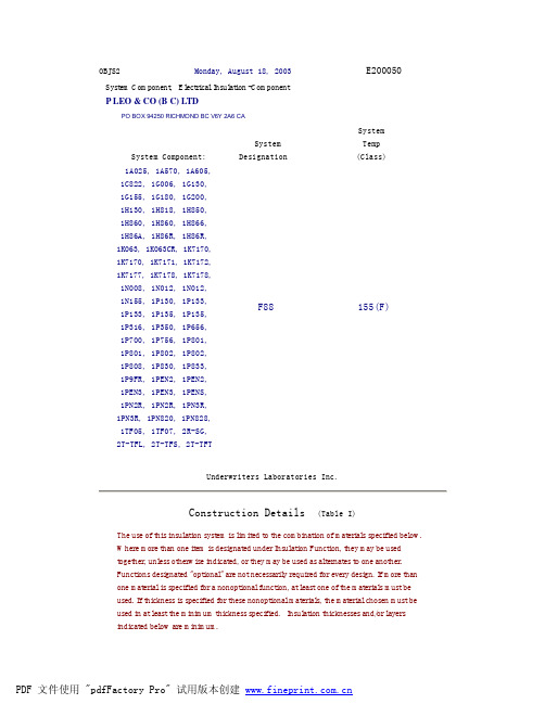
OBJS2Monday, August 18, 2003E200050 System Component, Electrical Insulation -ComponentP LEO & CO (B C) LTDPO BOX 94250 RICHMOND BC V6Y 2A6 CASystem Component:SystemDesignationSystemTemp(Class)1A025, 1A570, 1A605,1C822, 1G006, 1G130,1G155, 1G180, 1G200,1H130, 1H818, 1H850,1H860, 1H860, 1H866,1H86A, 1H86R, 1H86R,1K063, 1K063CR, 1K7170,1K7170, 1K7171, 1K7172,1K7177, 1K7178, 1K7178,1N008, 1N012, 1N012,1N155, 1P130, 1P133,1P133, 1P135, 1P135,1P316, 1P350, 1P656,1P700, 1P756, 1P801,1P801, 1P802, 1P802,1P808, 1P830, 1P833,1P9FR, 1PEN2, 1PEN2,1PEN3, 1PEN3, 1PENS,1PN2R, 1PN2R, 1PN3R,1PN3R, 1PN820, 1PN828,1TF05, 1TF07, 2R-SG,2T-TFL, 2T-TFS, 2T-TFTF88 155(F)Underwriters Laboratories Inc.Construction Details (Table I)The use of this insulation system is limited to the combination of materials specified below. Where more than one item is designated under Insulation Function, they may be used together, unless otherwise indicated, or they may be used as alternates to one another. Functions designated "optional" are not necessarily required for every design. If more than one material is specified for a nonoptional function, at least one of the materials must be used. If thickness is specified for these nonoptional materials, the material chosen must be used in at least the minimum thickness specified. Insulation thicknesses and/or layers indicated below are minimum.Winding Wire - Recognized Component - Magnet wire (OBMW2), single build or greater or- Recognized Component - Single and Multi-Layer Insulated Winding Wire (OBJT2) or- Recognized Component - Appliance Wiring Material (AVLV2)(unless otherwise noted, winding wire types listed below may be used in combination within a single product) MW 79 or 155C PolyurethaneMW 80 or 155C Polyurethane (Polyamide)MW 82 or 180C PolyurethaneMW 83 or 180C Polyurethane (Polyamide)FurukawaTEX-F 4.72 mils (0.12 mm) triple insulatedRubadue Wire Co. Inc.FEP wire 4.06 mils (0.1 mm) double or triple layer insulatedTCA3 3.62 mils (0.09 mm) double or triple layer insulatedTefzel wire 3.62 mils (0.09 mm) double or triple layer insulated Totoku ElectricTIW-3 3.86 mils (0.1 mm) triple insulatedTIW-E 3.86 mils (0.1 mm) triple insulatedGround & Interwinding InsulationDesignation (No.)mils(mm)CommentsDuPontKaladex2000 1 (0.03)Kapton 100CR 1 (0.03)Kapton 100HA 1 (0.03)Kapton 100HN 1 (0.03)Kapton 100PST 1 (0.03)Nomex 410 5(layers)P. Leo1H130 3(layers)1H860 3(layers)1H866 1(layers)1H86R 1(layers)1K7170 1(layers) Recognized Component - Insulating Tape (OANZ2)1K7177 1(layers) Recognized Component - Insulating Tape (OANZ2)1K7178 1(layers)1N012 2(layers)1P133 3(layers)1P135 3(layers)1P801 5(layers) Recognized Component - Insulating Tape (OANZ2)1P802 5(layers) Recognized Component - Insulating Tape (OANZ2)1PEN2 1(layers) Recognized Component - Insulating Tape (OANZ2)1PEN3 1(layers) Recognized Component - Insulating Tape (OANZ2)1PN2R 1(layers) Recognized Component - Insulating Tape (OANZ2)1PN3R 1(layers) Recognized Component - Insulating Tape (OANZ2)Sumitomo 3M LtdSuper 10-T 2(layers) Recognized Component - Insulating Tape (OANZ2)Super 10-W 2(layers) Recognized Component - Insulating Tape (OANZ2)Sumitomo BakeliteSumikon AM-3200 11.8(0.3)DAP Molding ComopundSumikon PM-9630 11.8(0.3)Phenolic Molding CompoundSumikon PM-9720 11.8(0.3)Phenolic Molding CompoundSumikon PM-9750 11.8(0.3)Phenolic Molding CompoundSumikon PM-9820 11.8(0.3)Phenolic Molding CompoundSumikon PM-9830 11.8(0.3)Phenolic Molding CompoundSumikon PM-9850 11.8(0.3)Phenolic Molding CompoundTeijin Dupont Films Japan Ltd.Teonex Q51 1 (0.03)Any Recognized Component Plastic (QMFZ2), polyethylene terphthalate film (PET), 5 mils (0.13 mm) - various manufacturers.Cores, Tubes, Bobbins (optional) (for mechanical support only) Designation (No.)CommentsCosmo LinkPTFE-LPTFE-TFurukawa ElectricPI-TubeGreat Holding Industrial Co., Ltd.TFLTFSTFTHitachi Cable LtdVerafit V2Kurabe IndustrialSE-1SE-2NikkanE-651U-1E-651U-2S-693-600S-693F-1Nissei ElectricRSU-1RSU-2P. Leo & Co. (B C) Ltd.2R-SG2T-TFL2T-TFS2T-TFTSumitomo Electical Fine Polymer Sumitube F2(z)Zeus Industrial Products Inc.TFE-LW-150TFE-SW-600TFE-TW-300Tapes (optional)Designation (No.)CommentsP Leo & Co (B C) Ltd1A0251A5701A6051C8221G006 aramid fiber (Nomex) paper1G130 glass cloth1G155 glass cloth1G180 glass cloth1G200 woven glass cloth, silicone adhesive 1H818 reinforced PET, rubber adhesive1H850 polyester film1H860 acrylic adhesive, polyester film1H86A1H86R1K063 silicone adhesive, polyimide film 1K063CR1K7170 Kapton film1K7171 silicone adhesive, polyimide film 1K7172 silicone adhesive, polyimide film1K71781N008 aramid fiber (Nomex), rubber adhesive 1N012 PET film, acrylic adhesive1N155 aramid fiber (Nomex), rubber adhesive 1P130 acrylic adhesive, polyester film1P133 PET film, acrylic adhesive1P135 PET film, acrylic adhesive1P3161P350 PET film, acrylic adhesive1P6561P700 polyester film1P7561P801 acrylic adhesive, polyester film1P802 acrylic adhesive, polyester film1P808 polyester film1P830 acrylic adhesive, polyester film1P833 PET film, acrylic adhesive1P9FR1PEN21PEN31PENS1PN2R1PN3R1PN820 woven polyester cloth1PN828 woven polyester cloth1TF051TF07Sumitomo 3M LimitedCU-35 (optional)Super 10-TSuper 10-W2245 (optional)Teraoka Seisakusho Co., Ltd.831S (optional)Tie Cords (optional)Designation (No.)CommentsTeijinBHT-44TPotting Compounds (optional)Designation (No.)CommentsGE Toshiba SiliconeTSE3331TSE3331KVarnishes (optional) Recognized Component - Varnishes (OBOR2) Designation (No.)CommentsHitachi Chemical Co. LtdWA-238AWF-285WP-2952F-2GWP-2952-F5John C. Dolph CoAC-43BC-346AKyocera Chemical Corp. (Toshiba Chemical)TVB-2024TVB-2180T++ ++ optional suffixMeiden Chemical#754XL Cannot be used with TEX-F#880P. D. George CoE468-2* Cannot be used with TEX-FE-468-2-7* May be followed by a one or two alphanumericsuffix indicating percent of insert fill and/orcolor.E-468-2FC* May be followed by a two three alphanumericsuffix indicating percent of insert fill and/orcolor.434 Air DryRipley Resin 468-2(+) May be followed by a two three alphanumericsuffix indicating percent of insert fill and/orcolor.711-F-2106P. D. George Co/SterlingY-21077X-010Viking ProductsV1380V1630Miscellaneous Minor Insulations (optional) Designation (No.)CommentsChang ChunPBT-4130 Coil coverE. I. Dupont de Nemours & Co.FR530 Coil cover Rynite, coil coverZytel 103HSLKolonKP212V0 Coil coverMitsubishi3010N Coil cover coil cover5010N6 coil coverTeijinCH7030 Coil cover coil coverCN7000 Coil cover coil coverCRN7000 Coil cover coil coverCRN7030 Coil cover coil coverToray Industries。
UCP600中英文版

ICC UNIFORM CUSTOMS AND PRACTICE FOR DOCUMENTARYCREDITSUCP 600英文FOREWORD (4)INTRODUCTION (6)ARTICLE 1 APPLICATION OF UCP (12)ARTICLE 2 DEFINITIONS (13)ARTICLE 3 INTERPRETATIONS (15)ARTICLE 4 CREDITS V。
CONTRACTS (17)ARTICLE 5 DOCUMENTS V。
GOODS, SERVICES OR PERFORMANCE (17)ARTICLE 6 AV AILABILITY,EXPIRY DATE AND PLACE FOR PRESENTATION (18)ARTICLE 7 ISSUING BANK UNDERTAKING (18)ARTICLE 8 CONFIRMING BANK UNDERTAKING (20)ARTICLE 9 ADVISING OF CREDITS AND AMENDMENTS (22)ARTICLE 10 AMENDMENTS (23)ARTICLE 11 TELETRANSMITTED AND PRE—ADVISED CREDITS AND AMENDMENTS (24)ARTICLE 12 NOMINATION (25)ARTICLE 13 BANK-TO—BANK REIMBURSEMENT ARRANGEMENTS (26)ARTICLE 14 STANDARD FOR EXAMINATION OF DOCUMENTS (27)ARTICLE 15 COMPLYING PRESENTATION (30)ARTICLE 16 DISCREPANT DOCUMENTS, W AIVER AND NOTICE (31)ARTICLE 17 ORIGINAL DOCUMENTS AND COPIES (33)ARTICLE 18 COMMERCIAL INVOICE (34)ARTICLE 19 TRANSPORT DOCUMENT COVERING AT LEAST TWO DIFFERENT MODES OF TRANSPORT (35)ARTICLE 20 BILL OF LADING (37)ARTICLE 21 NON-NEGOTIABLE SEA W AYBILL (40)ARTICLE 22 CHARTER PARTY BILL OF LADING (43)ARTICLE 23 AIR TRANSPORT DOCUMENT (44)ARTICLE 24 ROAD,RAIL OR INLAND W ATERWAY TRANSPORT DOCUMENTS (46)ARTICLE 25 COURIER RECEIPT, POST RECEIPT OR CERTIFICATE OF POSTING (48)ARTICL E 26 "ON DECK", ”SHI PPER'S LOAD AND COUN T”,“SAID BY SHIPPER TO CONTAIN”AND CHARGES ADDITIONAL TO FREIGHT (49)ARTICLE 27 CLEAN TRANSPORT DOCUMENT (50)ARTICLE 28 INSURANCE DOCUMENT AND COVERAGE (50)ARTICLE 29 EXTENSION OF EXPIRY DATE OR LAST DAY FOR PRESENTATION (52)ARTICLE 30 TOLERANCE IN CREDIT AMOUNT,QUANTITY AND UNIT PRICES (53)ARTICLE 31 PARTIAL DRA WINGS OR SHIPMENTS (54)ARTICLE 32 INSTALMENT DRA WINGS OR SHIPMENTS (55)ARTICLE 33 HOURS OF PRESENTATION (55)ARTICLE 34 DISCLAIMER ON EFFECTIVENESS OF DOCUMENTS (55)ARTICLE 35 DISCLAIMER ON TRANSMISSION AND TRANSLATION (56)ARTICLE 36 FORCE MAJEURE (57)ARTICLE 37 DISCLAIMER FOR ACTS OF AN INSTRUCTED PARTY (57)ARTICLE 38 TRANSFERABLE CREDITS (58)ARTICLE 39 ASSIGNMENT OF PROCEEDS (62)UCP600中文版UCP600第一条UCP的适用范围 (62)第二条定义 (63)第三条解释 (64)第四条信用证与合同 (65)第五条单据与货物、服务或履约行为 (65)第六条兑用方式、截止日和交单地点 (65)第七条开证行责任 (66)第八条保兑行责任 (66)第九条信用证及其修改的通知 (67)第十条修改 (68)第十一条电讯传输的和预先通知的信用证和修改 (69)第十二条指定 (69)第十三条银行之间的偿付安排 (69)第十四条单据审核标准 (70)第十五条相符交单 (71)第十六条不符单据、放弃及通知 (72)第十七条正本单据及副本 (73)第十八条商业发票 (73)第十九条涵盖至少两种不同运输方式的运输单据 (74)第二十条提单 (75)第二十一条不可转让的海运单 (76)第二十二条租船合同提单 (78)第二十三条空运单据 (79)第二十四条公路、铁路或内陆水运单据 (80)第二十五条快递收据、邮政收据或投邮证明 (81)第二十六条“货装舱面”、“托运人装载和计数”、“内容据托运人报称”及运费之外的费用. (81)第二十七条清洁运输单据 (81)第二十八条保险单据及保险范围 (82)第二十九条截止日或最迟交单日的顺延 (83)第三十条信用证金额、数量与单价的伸缩度 (83)第三十一条部分支款或部分发运 (83)第三十二条分期支款或分期发运 (84)第三十三条交单时间 (84)第三十四条关于单据有效性的免责 (84)第三十五条关于信息传递和翻译的免责 (84)第三十六条不可抗力 (85)第三十七条关于被指示方行为的免责 (85)第三十八条可转让信用证 (86)第三十九条款项让渡 (88)FOREWORDThis revision of the Uniform Customs and Practice for Documentary Credits (commonly called “UCP”) is the sixth revision of the rules since they were first promulgated in 1933.It is the fruit of more than three years of work by the International Chamber of Commerce’s (ICC)Commission on Banking Technique and Practice。
电子流压差控6路6位线程(EPIV)说明书
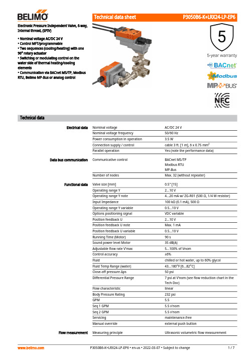
Electronic Pressure Independent Valve, 6-way,Internal thread, (EPIV)• Nominal voltage AC/DC 24 V• Control MFT/programmable• Two sequences (cooling/heating) with one90° rotary actuator• Switching or modulating control on thewater side of thermal heating/coolingelements• Communication via BACnet MS/TP, ModbusRTU, Belimo MP-Bus or analog controlTechnical dataElectrical data Nominal voltage AC/DC 24 VNominal voltage frequency50/60 HzPower consumption in operation 3.5 WConnection supply / control cable 3 ft. [1 m], 6 x 0.75 mm²Parallel operation Yes (note the performance data) Data bus communication Communicative control BACnet MS/TPModbus RTUMP-BusNumber of nodes Max. 32 (without repeater)Functional data Valve size [mm]0.5" [15]Operating range Y 2...10 VOperating range Y note 4...20 mA w/ ZG-R01 (500 Ω, 1/4 W resistor)Input Impedance100 kΩ (0.1 mA), 500 ΩOperating range Y variable0.5...10 VOptions positioning signal VDC variablePosition feedback U 2...10 VPosition feedback U note Max. 1 mAPosition feedback U variable0.5...10 VRunning Time (Motor)90 sSound power level Motor35 dB(A)Adjustable flow rate V'max 5...100% of VnomControl accuracy±6%Fluid chilled or hot water, up to 60% glycolFluid Temp Range (water)43...180°F [6...82°C]Close-off pressure ∆ps50 psiDifferential Pressure Range7 psi at V’nom (see flow reduction chart in theTech Doc)Flow characteristic linearBody Pressure Rating232 psiGPM 5.5Seq 1 GPM 5.5 v'nomSeq 2 GPM 5.5 v'nomServicing maintenance-freeManual override external push buttonFlow measurement Measuring principle Ultrasonic volumetric flow measurement••••Flow measurementMeasuring accuracy flow ±2%Min. flow measurement 1% of V'nom Measurement Repeatability±0.5% (Flow)Safety dataDegree of protection IEC/EN IP54Degree of protection NEMA/UL NEMA 2Enclosure UL Enclosure Type 2Agency ListingcULus acc. to UL60730-1A/-2-14, CAN/CSA E60730-1:02, CE acc. to 2014/30/EU and2014/35/EU; Listed to UL 2043 - suitable for use in air plenums per Section 300.22(c) of the NEC and Section 602.2 of the IMC Quality Standard ISO 9001Ambient temperature -22...122°F [-30...50°C]Storage temperature -40...176°F [-40...80°C]Ambient humidityMax. 95% RH, non-condensing MaterialsValve body Nickel-plated brass body Spindle nickel-plated brass Spindle seal EPDM (lubricated)SeatPTFECharacterized disc chrome plated steel O-ring EPDMBallchrome plated brassSafety notesThis device has been designed for use in stationary heating, ventilation and air-conditioning systems and must not be used outside the specified field of application, especially in aircraft or in any other airborne means of transport.Outdoor application: only possible in case that no (sea) water, snow, ice, insolation or aggressive gases interfere directly with the actuator and that is ensured that the ambient conditions remain at any time within the thresholds according to the data sheet.Only authorized specialists may carry out installation. All applicable legal or institutional installation regulations must be complied during installation.The device contains electrical and electronic components and must not be disposed of as household refuse. All locally valid regulations and requirements must be observed.Product featuresFlow/Mounting detailsMode of operationFlow measurementDefinitionCreep flow suppressionConfigurable actuatorsHydronic balancingProduct featuresThe final controlling device consists of three components: 6-way characterized control valve, measuring pipe with volumetric flow sensor and the actuator itself. The adjusted maximum flows for sequence 1 (V'max1) and sequence 2 (V'max2) are assigned to the positioning signal (2V/0% for sequence 1, 10 V/100% for sequence 2).The performance device can be controlled communicatively or by an analog signal. The fluid is detected by the sensor in the measuring pipe and is applied as the flow value. The measured value is balanced with the setpoint. The actuator corrects the deviation by changing the valve position.All flow tolerances are at 68°...77°F [20°... 25°C] and 0% glycol.V'nom is the maximum possible flow. (V'nom=V'nom1=V'nom2)V'max1 is the maximum flow rate which has been set with the smallest positioning signal, 2 V / 0%.V'max2 is the maximum flow rate which has been set with the highest positioning signal, 10 V / 100%.V'max1 and V'max2 can be adjusted 5...100% of V'nom.V'min 0% (non-variable).Given the very low flow speed in the opening point, this can no longer be measured by the sensor within the required tolerance. This range is overridden electronically.Opening sequenceThe valve remains closed until the volumetric flow required by the positioning signal Ycorresponds to 1% of V'nom. The control along the valve characteristic curve is active after this value has been exceeded.Closing sequenceThe control along the valve characteristic curve is active up to the required flow rate of 1% of V'nom. Once the level falls below this value, the flow rate is maintained at 1% of V'nom. If the level falls below the flow rate of 0.5% of V'nom required by the reference variable Y, then thevalve will close.The factory settings cover the most common applications.With the ZTH US and the Belimo Assistant App, the maximum flow rates of sequence 1 and sequence 2 can be adjusted individually on-site in a few simple reliable steps.Combination analogue - communicative(hybrid mode)Manual override High functional safetyPosition feedbackPressure compensationWith conventional control by means of an analog positioning signal, BACnet or Modbus can be used for the communicative position feedback.Manual override with push-button possible (the gear is disengaged for as long as the button is pressed or remains locked).The actuator is overload protected, requires no limit switches and automatically stops when the end stop is reached.Regardless of the setting of the control mode, the feedback signal U5 is always assigned to the flow V'max1 and V'max2.In cases of combined heating/cooling control elements, the fluid remains in the control element when in the closed position (no heating or cooling). The pressure of the enclosed fluid can rise or fall due to changes in fluid temperature caused by the ambient temperature. The 6-way characterized control valves have an integrated pressure relief function for the purpose of compensating for such pressure changes.The pressure relief function is active in the closed position (45°) of the valve; reliable separation of Sequences 1 and 2 continues. For additional information, consult the notes for project planning for the 6-way characterized control valve.Electrical installationSupply from isolating transformer.Parallel connection of other actuators possible. Observe the performance data.The wiring of the line for BACnet MS/TP / Modbus RTU is to be carried out in accordance with applicable RS485 regulations.Modbus / BACnet: Supply and communication are not galvanically isolated. Connect earth signal of the devices with one another.AC/DC 24 V, modulatingCable colors:1 = black 2 = red 3 = white 5 = orange 6 = pink 7 = greyOperation on the MP-BusCable colors:1 = black 2 = red 3 = white 5 = orange 6 = pink 7 = greyBACnet MS/TP / Modbus RTUC₁ = D- = A C₂ = D+ = BRecommended installation positionsWater quality requirementsServicingFlow directionModbus RTU / BACnet MS/TP with analogue setpoint (hybrid mode)C₁ = D- = A C₂ = D+ = BInstallation notesThe ball valve can be installed upright to horizontal. The ball valve may not be installed in ahanging position, i.e. with the spindle pointing downwards.Belimo valves are regulating devices. For the valves to function correctly in the long term, they must be kept free from particle debris (e.g. welding beads during installation work). The installation of a suitable strainer is recommended.Ball valves, rotary actuators and sensors are maintenance-free.Before any service work on the final controlling device is carried out, it is essential to isolate the rotary actuator from the power supply (by unplugging the electrical cable if necessary). Any pumps in the part of the piping system concerned must also be switched off and theappropriate slide valves closed (allow all components to cool down first if necessary and always reduce the system pressure to ambient pressure level).The system must not be returned to service until the ball valve and the rotary actuator have been correctly reassembled in accordance with the instructions and the pipeline has been refilled by professionally trained personnel.The flow direction must be observed. The position of the ball can be identified from the L-marking on the damper shaft.Heating and cooling in position accuracyValve characteristic curveNFC connectionThe lower diagram shows the flow characteristic depending on the control signal.Valve characteristic curveServiceBelimo devices marked with the NFC logo can be operated with the Belimo Assistant App.Requirement:- NFC- or Bluetooth-capable smartphone- Belimo Assistant App (Google Play & Apple AppStore)Align NFC-capable smartphone on the device so that both NFC antennas are superposed.Connect Bluetooth-enabled smartphone via the Bluetooth-to-NFC Converter ZIP-BT-NFC to thedevice. Technical data and operation instructions are shown in the ZIP-BT-NFC data sheet.Service Tools connectionZTH EU connectionDimensionsDimensional drawingsA B C D E F G10.2" [260]9.5" [241]7.4" [187] 5.9" [150] 4.3" [110]7.9" [201] 2.6" [65]。
PI6C20800中文资料
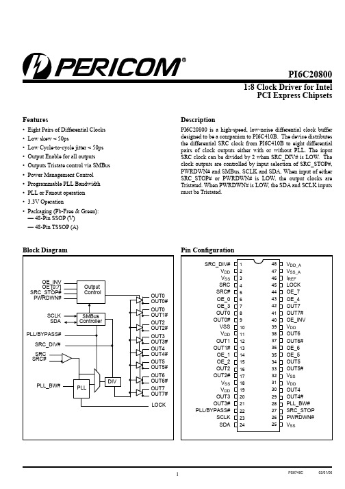
Features• Eight Pairs of Differential Clocks • Low skew < 50ps• Low Cycle-to-cycle jitter < 50ps • Output Enable for all outputs • Outputs Tristate control via SMBus • Power Management Control • Programmable PLL Bandwidth • PLL or Fanout operation • 3.3V Operation• Packaging (Pb-Free & Green):— 48-Pin SSOP (V) — 48-Pin TSSOP (A)DescriptionPI6C20800 is a high-speed, low-noise differential clock buffer designed to be a companion to PI6C410B. The device distributes the differential SRC clock from PI6C410B to eight differential pairs of clock outputs either with or without PLL. The input SRC clock can be divided by 2 when SRC_DIV# is LOW. The clock outputs are controlled by input selection of SRC_STOP#, PWRDWN# and SMBus, SCLK and SDA. When input of either SRC_STOP# or PWRDWN# is LOW, the output clocks are Tristated. When PWRDWN# is LOW, the SDA and SCLK inputs must be Tristated.PCI Express ChipsetsPin ConfigurationV DD_A V SS_A I REF LOCK OE_7OE_4OUT7OUT7#OE_INV V DD OUT6OUT6#OE_6OE_5OUT5OUT5#V SS V DD OUT4OUT4#PLL_BW#SRC_STOP PWRDWN# V SS484746454443424140393837363534333231302928272625123456789101112131415161718192021222324SRC_DIV#V DD V SS SRC SRC#OE_0OE_3OUT0OUT0#VSS V DD OUT1OUT1#OE_1OE_2OUT2OUT2#V SS V DD OUT3OUT3#PLL/BYPASS#SCLK SDAPI6C208001:8 Clock Driver for IntelPCI Express ChipsetsPin DescriptionsPin Name Type Pin #DescriptionsSRC_DIV#Input1 3.3V LVTTL input for selecting input frequency divide by 2,active LOW.SRC & SRC#Input4, 50.7V Differential SRC input from PI6C410 clock synthesizerOE [0:7]Input6, 7, 14, 15, 35, 36,43, 44 3.3V LVTTL input for enabling outputs, active HIGH.OE_INV Input403.3V LVTTL input for inverting the OE, SRC_STOP# and PWRDWN# pins.When 0 = same stageWhen 1 = OE[0:7], SRC_STOP#, PWRDWN# inverted.OUT[0:7] & OUT[0:7]#Output8, 9, 12, 13, 16 17,20, 21, 29, 30, 33, 34,37, 38, 41, 420.7V Differential outputsPLL/BYPASS#Input22 3.3V LVTTL input for selecting fan-out of PLL operation. SCLK Input23SMBus compatible SCLOCK inputSDA I/O24SMBus compatible SDATAI REF Input46External resistor connection to set the differential output current SRC_STOP#Input27 3.3V LVTTL input for SRC stop, active LOWPLL_BW#Input28 3.3V LVTTL input for selecting the PLL bandwidth PWRDWN# Input26 3.3V LVTTL input for Power Down operation, active LOW LOCK Output45 3.3V LVTTL output, transition high when PLL lock is achieved(Latched output)V DD Power2, 11, 19, 31, 39 3.3V Power Supply for OutputsV SS Ground3, 10, 18, 25, 32Ground for OutputsV SS_A Ground47Ground for PLLV DD_A Power48 3.3V Power Supply for PLLSerial Data Interface (SMBus)PI6C20800 is a slave only SMBus device that supports indexed block read and indexed block write protocol using a single 7-bit address and read/write bit as shown below.Address assignmentA6A5A4A3A2A1A0R/W 11011100/1 Data Protocol(1)1 bit7 bits118 bits18 bits18 bits18 bits1 1 bitStart bit SlaveAddr R/W AckRegisteroffset AckByteCount= NAck DataByte 0AckDataByte N- 1Ack StopbitNote:1. Register offset for indicating the starting register for indexed block write and indexed block read. Byte Count in write mode cannot be 0.PI6C208001:8 Clock Driver for IntelPCI Express ChipsetsData Byte 0: Control RegisterBit DescriptionsType Power Up ConditionOutput(s) Affected Pin 0SRC_DIV#0 = Divide by 21 = Normal RW1 = x1OUT[0:7], OUT[0:7]#NA1PLL/BYPASS#0 = Fanout 1 = PLLRW 1 = PLL OUT[0:7], OUT[0:7]#NA2PLL Bandwidth0 = HIGH Bandwidth,1 = LOW Bandwidth RW 1 = Low OUT[0:7], OUT[0:7]#NA 3TBD NA 4TBD NA 5TBDNA6SRC_STOP#0 = Driven when stopped 1 = TristateRW0 = Driven when stoppedOUT[0:7], OUT[0:7]#7PWRDWN#0 = Driven when stopped 1 = TristateRW 0 = Driven when stopped OUT[0:7], OUT[0:7]#NAData Byte 1: Control RegisterBit DescriptionsType Power Up ConditionOutput(s) Affected Pin 0OUTPUTS enable 1 = Enabled 0 = Disabled RW 1 = Enabled OUT0, OUT0#NA 1RW 1 = Enabled OUT1, OUT1#NA 2RW 1 = Enabled OUT2, OUT2#NA 3RW 1 = Enabled OUT3, OUT3#NA 4RW 1 = Enabled OUT4, OUT4#NA 5RW 1 = Enabled OUT5, OUT5#NA 6RW 1 = Enabled OUT6, OUT6#NA 7RW1 = EnabledOUT7, OUT7#NAPI6C208001:8 Clock Driver for IntelPCI Express ChipsetsData Byte 2: Control RegisterBit DescriptionsType Power Up Condition Output(s) Affected Pin 0Allow control of OUTPUTS with assertion of SRC_STOP#0 = Free running1 = Stopped with SRC_Stop#RW 0 = Free running OUT0, OUT0#NA 1RW 0 = Free running OUT1, OUT1#NA 2RW 0 = Free running OUT2, OUT2#NA 3RW 0 = Free running OUT3, OUT3#NA 4RW 0 = Free running OUT4, OUT4#NA 5RW 0 = Free running OUT5, OUT5#NA 6RW 0 = Free running OUT6, OUT6#NA 7RW0 = Free runningOUT7, OUT7#NAData Byte 3: Control RegisterBit DescriptionsType Power Up ConditionOutput(s) AffectedPin0TBD RW 1RW 2RW 3RW 4RW 5RW 6RW 7RWData Byte 4: Pericom ID RegisterBit DescriptionsType Power Up ConditionOutput(s) AffectedPin 0Pericom ID R 0NA NA 1R 0NA NA 2R 0NA NA 3R 0NA NA 4R 0NA NA 5R 1NA NA 6R 0NA NA 7RNANAPI6C208001:8 Clock Driver for IntelPCI Express ChipsetsFunctionalityPWRDWN#OUT OUT#SRC_Stop#OUT OUT#1Normal Normal 1Normal Normal 0I REF × 2 or FloatLOWI REF × 6 or FloatLOWFigure 1. Power down sequencePI6C208001:8 Clock Driver for IntelPCI Express ChipsetsDifferential Clock Buffer characteristicsSymbol Minimum Maximum R O 3000ΩN/A R OS unspecified unspecified V OUTN/A850mVCurrent AccuracySymbol Conditions Configuration LoadMin.Max.I OUTV DD = 3.30 ±5%R REF = 475Ω 1%I REF = 2.32mANominal test load for given configuration-12%I NOMINAL +12%I NOMINAL Note:1. I NOMINAL refers to the expected current based on the configuration of the device.Differential Clock Output CurrentBoard Target Trace/Term Z Reference R, Iref = V DD /(3xRr)Output Current V OH @ Z 100Ω(100Ω differential ≈ 15% coupling ratio)R REF = 475Ω 1%, I REF = 2.32mAI OH = 6 x I REF0.7V @ 50PI6C208001:8 Clock Driver for IntelPCI Express ChipsetsAbsolute Maximum Ratings (1) (Over operating free-air temperature range)Symbol ParametersMin.Max.UnitsV DD_A 3.3V Core Supply V oltage -0.5 4.6V V DD 3.3V I/O Supply V oltage -0.54.6V IH Input HIGH V oltage 4.6V IL Input LOW V oltage -0.5 Ts Storage Temperature -65150°C V ESDESD Protection2000VNote:1. Stress beyond those listed under “Absolute Maximum Ratings” may cause permanent damage to the device.DC Electrical Characteristics (V DD = 3.3±5%, V DD_A = 3.3±5%)Symbol Parameters ConditionMin.Max.UnitsV DD_A 3.3V Core Supply V oltage 3.135 3.465V V DD 3.3V I/O Supply V oltage 3.135 3.465V IH 3.3V Input HIGH V oltage V DD 2.0V DD + 0.3V IL 3.3V Input LOW V oltage V SS – 0.30.8I IK Input Leakage Current 0 < V IN < V DD -5+5μA V OH 3.3V Output HIGH V oltage I OH = -1mA 2.4V V OL 3.3V Output LOW V oltage I OL = 1mA 0.4I OH Output HIGH Current I OH = 6 x I REF , I REF = 2.32mA12.2mA 15.6C IN Logic Input Pin Capacitance 1.55pF C OUT Output Pin Capacitance6L PIN Pin Inductance 7nH I DD Power Supply Current V DD = 3.465V , F CPU = 200MHz250mAI SS Power Down Current Driven outputs 60I SS Power Down Current Tristate outputs12T AAmbient Temperature70°CPI6C208001:8 Clock Driver for IntelPCI Express ChipsetsAC Switching Characteristics (1,2,3) (V DD = 3.3±5%, V DD_A = 3.3±5%)Symbol ParametersMin Max.UnitsNotes T rise / T fall Rise and Fall Time (measured between 0.175V to 0.525V)175700ps 2ΔT rise / ΔT fall Rise and Fall Time Variation 1252T skew Output-to-Output Skew 50ps 3V HIGH V oltage HIGH 660850mV2V OVS Max. V oltage 1150V UDS Min. V oltage -300V LOW V oltage LOW-150+1502V cross Absolute crossing poing voltages 2505502ΔV cross Total Variation of V cross over all edges 1402T DC Duty Cycle4555%3T jcyc-cycJitter, Cycle-to-cycle (PLL Mode, Measurement for differential waveform)50psJitter, Cycle-to-cycle (BYPASS mode as additive jitter)Notes:1. Test configuration is R S = 33.2Ω, Rp = 49.9Ω, and 2pF.2. Measurement taken from Single Ended waveform.3. Measurement taken from Differential waveform.Configuration Test Load Board TerminationPI6C208001:8 Clock Driver for IntelPCI Express ChipsetsPackaging Mechanical: 48-Pin TSSOP (A)PI6C208001:8 Clock Driver for IntelPCI Express ChipsetsOrdering Information(1,2)Ordering Code Package Code Package Description PI6C20800VE VE48-pin, 300-mil wide, SSOP, Pb-Free and GreenPI6C20800AE AE48-pin, 240-mil wide, TSSOP, Pb-Free and GreenNotes:1. Thermal characteristics can be found on the company web site at /packaging/2. E = Pb-free and GreenPericom Semiconductor Corporation • 1-800-435-2336 • 。
AE DC电源说明书 汉化版

PAGE 5客户反馈对此说明书的格式或内容有任何意见都可以发送邮件至:Tech.writing@要订购一份说明书,请联系技术支持:Technical.support@PAGE 7目录第一章. 安全与产品兼容性指导重要安全信息……1-1说明书中的危险,警告,和注意提示框……1-2安全指导……1-2安全安装与运作的规则……1-2产品标签解释……1-3产品兼容性……1-5产品证书……1-5安全和EMC 标示与标准……1-6电磁兼容性(EMC)标示与标准……1-6安全标示与标准……1-7工业指导……1-7使用的条件……1-7第二章. 操作原理整体说明……2-1输出阻抗的范围……2-1输出调节……2-1接口……2-1微处理器的优点……2-2显示……2-2抑弧特性……2-2运作原理……2-2输入……2-3家务管理式供应……2-3转向器……2-3输出……2-3输出范围……2-3逻辑控制……2-4远程接口……2-4第三章. 产品规格功能规格……3-1物理规格……3-3尺寸工程图……3-5电气规格……3-6环境规格……3-12冷却规格……3-13PAGE 8第四章. 通信接口用户接口……4-1连接器……4-1信号……4-3模拟信号……4-3数字信号……4-3引脚说明……4-3接触器互锁端口……4-10接触器互锁端口连接器……4-10接触器互锁线缆要求……4-11接触器互锁端口引脚描述……4-12 被动显示面板……4-14显示……4-14LEDs……4-15主动前面板/Pinnacle 远程面板……4-16 连接到远程主动面板……4-16面板的理解……4-18控制按键……4-18输出显示画面……4-18软键……4-18修改旋钮……4-19调节按钮……4-19开关按钮和LED指示灯……4-19放电LED指示灯……4-19控制面板界面……4-19输出功率按钮……4-20控制按钮……4-20调节按钮……4-21双线输出显示画面……4-21软键……4-22修改旋钮……4-22控制面板的控制……4-22菜单选项的理解……4-23使用服务功能……4-25确认服务类型错误……4-26确认服务类型统计……4-26确认总能量输出……4-26确认总的空闲时间……4-26确认错误的数量……4-26确认循环的数量……4-27检查你的装置……4-27观察从属装置的地址……4-27确认你的错误主/从系统……4-28确认你的硬件结构……4-28确认你的软件逻辑……4-29PAGE 9确认你的ROM……4-29确认你的软件版本……4-29使用供应功能……4-29设定AE总线的终止时间……4-30设定供应参数……4-30设定面板模式……4-30选择远程或者本地模式…4-30选择一个上锁编码……4-31选择Clicks的数量……4-31设定程序源……4-31使用进程功能……4-32监视你的进程……4-32设定并观察主/从系统诊断建立一个最小的进程电压……4-34设定一个超出设定点的计时器……4-34 修改靶材功能……4-35设定进程极限……4-36设定一个电压跳脱的极限…… 4-37设定一个输出电压的最大极限……4-38 设定一个输出电流的最大极限……4-38 设定一个输出功率的最大极限……4-38 设定放电的处理……4-39设定放电电压的Trip水平……4-39设定放电特征……4-39设定放电计数极限……4-40观察放电密度……4-40修改放电密度窗口的长度……4-41设定放电统计持续期间窗口……4-41设定放电的次数……4-42预定义放电处理……4-42启用放电处理……4-43设定控制参数……4-44设定处方……4-44设定波动水平……4-45使用靶材条件循环(TCC)……4-46启用靶材条件循环(TCC)……4-46设定靶材条件循环(TCC)计时器……4-46设定焦耳模式……4-47设定焦耳设定点……4-47设定焦耳起始点……4-47设定上升坡度……4-48标准系列(闪存)端口……4-49标准系列端口描述……4-49传送参数……4-50AE总线(主)端口……4-50AE总线(主)连接器和引脚描述……4-51AE总线传送参数……4-51PAGE 10设定装置的网络地址……4-52按钮的类型和设置……4-52外部DIPs……4-54内部DIPs……4-55最小开关……4-56可能的网络地址的按键设定……4-57设定Baud速率和通信模式……4-58AE总线(主)通信……4-59AE总线协议……4-59AE总线头字节……4-59AE总线命令数字字节……4-60AE总线选项长度字节……4-60AE总线数据字节……4-60AE总线检查加总字节……4-61创建一个理想的通信交易…4-62T0:主传送信息包……4-62T1:单元核实主传送包……4-62T2:单元传送到主机的响应……4-63T3:主机获得响应单元……4-63AE总线通信交易实例……4-64AE总线命令……4-64AE总线命令状态响应(CSR)代码……4-64AE总线命令设定……4-66命令序列事例……4-108单元解说……4-111第五章. 安装,建立,和运作装置的安装前准备……5-1安装空间需求……5-1冷却需求……5-1陈列柜涉及……5-2安装需求……5-6打开装置的包装……5-6装置的安装……5-6接地……5-7连接接触器Intlk端口……5-8连接一个远程被动面板……5-9连接一个Pinnacle远程主动面板……5-9连接到标准系列端口……5-9连接系列(主)端口控制……5-9连接用户端口控制……5-10连接输入电源……5-10输入电源线缆需求……5-14 Ring-Lug输入连接器……5-105 终端输入连接器……5-12连接输出电源……5-13PAGE 11三终端,多接触可插入式连接器(标准)……5-13连接放电连接性能…….5-23连接主/从运作……5-24主从运作的理解…….5-24主/从主卡接口……5-24构建一个主/从系统……5-25主/从结构事例……5-27后部面板图纸……5-2装置的运作……5-29普通运作……5-29放电处理的理解……5-31电压放电(V-Arc)的跳脱水平……5-32TCC算法启用……5-32靶材类型:金属……5-33靶材类型:非金属……5-33靶材类型:Custom…….5-33放电检测延迟时间……5-34放电关闭时间……5-36放电极限响应……5-38放电链接运作……5-39Pinnacle总线错误的理解……5-39总线错误的类型……5-39如果10毫秒总线错误连续地发生……5-39 主/从系统运作……5-40主/从输入开/关结合……5-41监视主/从系统……5-43清除主/从系统中的错误……5-43第六章. 故障处理和全球服务在打电话给AE全球服务之前……6-1首先确认……6-1确认电源关……6-1确认电源开……6-1确认如果输出不开启……6-3帮助代码问题解决表……6-4被动显示面板代码……6-6LED故障处理表……6-7清除错误代码……6-8错误代码故障处理表……6-8主/从错误向量从状态高字节……6-22从状态低字节……6-22个人卡状态……6-23联系AE全球服务……6-24先进能量世界总部,24*7技术支持……6-24及其返修……6-24PAGE 13图片清单……PAGE 15表格清单……PAGE 25总体描述AE系列直流电源提供了直流电源方面最大的优势。
Philips AE1120 EN 用户手册说明书
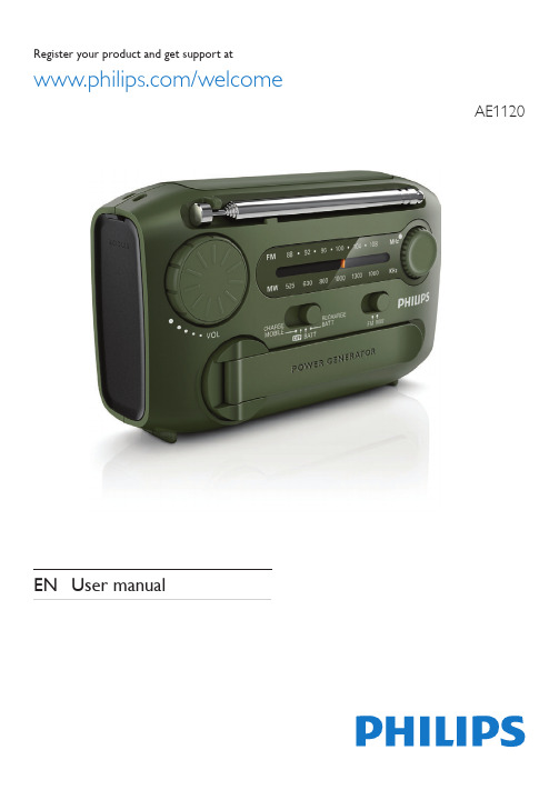
3 Close the battery compartment. 4 Slide the power source selector to BATT.
(Fig. ) »» The portable radio is operated on the
alkaline batteries.
d
EN 4
Tip
Tip
•• To avoid radio interference, do not listen to the radio
while charging your phone or built-in battery.
5 EN
Charge mobile phone
This portable radio can also serve as an emergency charger for your mobile phone. In places where AC outlet is unavailable, your phone will never run out of power with this device.
2 Adjust the FM•MW slider to select FM or
MW tuner.
3 Rotate the tuning knob to tune to a radio
station.
4 Rotate the volume knob to adjust volume.
(Fig. )
What's in the box
Check and identify the contents of your package. (Fig. )
b
Operate on alkaline batteries
Pyle PCO800 19英寸机柜内1800瓦电源条件器说明书
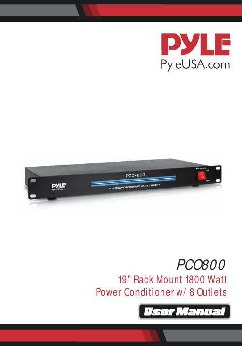
PCO800 19'' Rack Mount 1800 WattPower Conditioner w/ 8 OutletsThis unit was developed using the expertise of professional sound engineers and working musicians. You will nd your new unit has superior performance and greater exibility than any other power conditioner in its price range. READ THIS MANUAL CAREFULLY TO GET THE MOST OUT OF YOUR NEW UNIT. FeaturesFor advanced RF/EMI noise ltering and the quietest operation of your equipment..• Triple mode varistor surge and spike protection• Eight rear outlets (with room for 4 “wall warts”)• 15 amp rating (1800 W) with rear panel circuit breaker (UL)• Rugged single rack space metal housing for maximum reliability2IMPORTANT SAFETY INSTRUCTIONSWARNING! When using electric products, basic precautions should always be followed, including the following:1. Read all the instruction before using the product.2. DO NOT use this product near water (e.g. near a bathtub, washbowl, kitchen sink, in a wet basement, or near a swimming pool etc.).3. This product should be used only with a cart or stand that will keep it level and stable and prevent wobbling.4. This product, in combination with amplifiers, headphones or speakers, may be capable of producing sound levels that could cause permanent hearing loss.Do not operate for a long period of time at a high volume level or at a level that is uncomfortable. If you experience many hearing loss or ringing in the ears,you should consult an audiologist.5. The product should be located so that its location or position does not interfere with its proper ventilation.6. The product should be located away from heat sources such as radiators, heatvent, or other devices (including amplifiers) that produce heat.7. The product should be connected to a power supply only of the type described in the operating instructions or as marked on the product.8. The power supply cord should:• Be undamaged• Never share an outlet or extension cord with other devices so that the outlet’s extension on cord’s power rating is exceeded.• Be left plugged into the outlet when left unused for a long period of time.9. Care should be taken so that objects do not fall into, and liquids are not spilled through, the enclosure’s openings.10. The products should be serviced by quali ed service personnel when:A. The power supply cord or the plug has been damaged.B. Objects have fallen into, or liquid has been spilled onto the product.C. The product has been exposed to rain.D. The product does not appear to operate normally or exhibits a markedchange in performance.E. The product has been dropped, or the enclosure damaged.11. Do not attempt to service the product beyond what is described in the user-maintenance instructions. All other servicing should be referred to qualifiedservice personnel.12. Do not defeat the safety purpose of the grounding-type plug, which features a third grounding prong. If this provided plug does not fit into your outlet, consult an electrician for replacement of the obsolete outlet.34FRONT & BACK PANEL FEATURES:1. POWER SWITCH: Outlet switch activates protection and filtration to all back panel outlets. To turn the unit ON or OFF, press the upper or lower portion of this button.2. POWER CORD: Heavy duty 14-gauge power cord for connection to the AC Power Mains (115V/60Hz).3. CIRCUIT BREAKER: Resettable 15 Amp thermal circuit breaker.4. 8 REAR PANEL OUTLETS: EMI/RFI Filtered, spike/surge protected and switched.INSTALLATION AND OPERATION1. The Power Conditioners are the perfect accessories for any rack mount system. Install in the top slot of a standard 19-inch rack, and the 8 switched AC outlets on the rear panel will provide full safety protection to al your rack equipment. These conditioners protect your delicate electronic equipment by combining a high voltage varistor surge and transient suppressor with an RFI/EMIinterference filter. The filter helps prevent noise from fluorescent lights, motors, and similar sources of “electronic pollution” from contaminating the AC feed to your senitive video, audio, vtr or computer circuits.2. Plug Power Cord (2) into a standard grounded 115V outlet.3. Plug sensitive electronic equipment into the 8 Rear Panel Outlets (4)4. Turn Outlet Power Switch (1) to “ON” position. Lit LED indicates conditionedpower to the connected equipment.FEATURES:• Triple Mode Varistor Surge And Spike Protection• Eight Rear Outlets (With Room For 4 '' Wall Warts'')Controlled By A Front Panel Switch• 15 Amp Rating With Rear Panel Circuit Breaker• Rugged Single Rack Space Metal Housing For Maximum Reliability• Eliminates Unwanted Radio Frequency Interference(RFI)and Electromagnetic Interference (EMI)• Overload and Surge Protection• 1U Rack Mountable• Steel Front Panel and Chassis• Push to ResetWHAT'S IN THE BOX:• 8-Outlet Rack Mount Power ConditionerTECHNICAL SPECS:• Power Supply: 120V/60Hz, Standard Socket• Construction Material: Iron• 4.9 Foot Power Cord (3x14 AWG)• Peak Impulse Current: 1500 Amps• Product Dimensions (L x W x H): 18.9'' x 7.28'' x 1.73'' -inchesThis products can expose you to a chemical or group of chemicals, whichmay include ”Nickel Carbonate”which is known in the state of California tocause cancer, birth defects, or other reproductive harm. For more info, go tohttps:///.5Questions? Issues?We are here to help! Phone: (1) 718-535-1800Email: *******************。
IP6.2脉冲耦合器说明书

IP 6.2Manual Surge Coupling UnitIP6.2 Coupling Unit (top) with a DEC1A decoupling unit (bottom)To be used for surge testsrequiring coupling on multiple wires.ONE SOLUTIONforþ IEC 1000-4-5 þ EN61000-4-5 þ FCC part 68 þ FTZ 12 TR1 þ ITU (CCITT) K20, K21the relevant part of EN 50082-1, -2all EN product standards and many other applications.FEATURESn 4 wire integrated unit n coupling CWG surges n coupling 10/700 surges n test circuit impedance maintained at 40 ohms n resistor, capacitor and gas arrestor coupling n manual operationn can be used with any surge generatorn impulse power 6.6kV n supplied to ISO 9001APPLICATIONIP6.2 surge coupler is used to couple the 1.2/50 µs, 8/20 µs, 10/160µs,10/560µs and 10/700 µs surge impulses on data, signal and telecom lines. Coupling is effected via gas arrestors, capacitors and resistors. The three coupling methods can be selected, depending on the signals to be transmitted.IP6.2 is used either on it’s own or with a decoupling unit such as the Haefely DEC 1A or DEC 3A.E s t a b l i s h e d 1981COST EFFETIVEHIGH PERFORMANCEEASY OPERATIONIn its standard form, theIP6.2 can be used for testing to IEC, FCC, FTZ and ITU (CCITT) standards.IP6.2 is able to cover so many standards thanks to a thorough understanding of telecoms requirements. Our commitment is yourguarantee. This concept enables different testmethods to be implemented at very little cost in time or money, thus protecting the financial investment and enabling customers to keep up with changing standards and test requirements. Typical standards which can be addressed are: • IEC 61000-4-5 (both impulse types) • ITU (CCITT) K20, K21 • FCC part 68IP6.2 is designed to a high technical specification for product quality, flexibility and personnel safety. The standard unit includes three coupling possibilities • resistors • capacitors • gas arrestorsIEC 61000-4-5 describes testing of up to 4 data and telecom cables. The test system must always have a 40 ohm impedance. An important feature of IP6.2 is it’s ability to maintain this impedance, fortelecoms testing, for both the 10/700 and CWG impulses.IP6.2 requires no external power supplies and can be operated with any surge generator up to 6.6kV.IP6.2 is a versatile unit for multiple line coupling. Front panel of the IP6.2 is a graphical representation of the coupling circuits making configuration to the different surge test standards fast and easy.• 40Ω / 25 to 100Ω • 40Ω / 0.5µF • 40Ω / 0.1µFCoupling paths are selected using high voltage safety plugs on the instrument front panel.Together with the Haefely EMC decoupling units:§ DEC1A(for analogue Telecom) § DEC3A(for I/O datalines)IP6.2 provides a cost effective straightforward solution to increasingly complex test standards.TECHNICAL SPECIFICATIONSurge Test Voltage 0.5 - 7.6 kVEUT voltage 500V (capacitor) 66V (arrestor) Coupling resistors 1x25, 2x50, 3x75, 4x100Ω EUT connectors 4 x 4mm banana plugs + ground Coupling capacitors 0.5µF / 0.1µF Surge connectors High and Common Coupling gas arrestors90VWeight10 KgORDERING INFORMATIONIP6.2 coupling unit249 518 DEC1A decoupling unit (analogue Telecom) 249 523 DEC3A decoupling unit (I/O datalines)249 524Issue 01/01Haefely Test AGBusiness Unit EMC Bernstrasse 90, P.O Box CH-8953 Dietikon-Zurich SwitzerlandPhone: ++ 41 61 373 41 11 Fax: ++ 41 61 373 45 99email ********************。
Speco Technologies ASPC20 增强型PA扬声器说明书

A S P C20 6” Amplified PA Horn SpeakerThank you for your choice of Speco Technologies’ ASPC20 Amplified PA Horn. This unit is designed and manufactured to provide an economical solution to the traditional amplifier and speaker setup, and is especially useful for external mobile audio installations. The sturdy ABS construction and power up to 20W max ensure a long and versatile life.DESCRIPTIONThe ASPC20 utilizes an integrated circuit (IC) for providing the necessary gain to raise a low audio input signal (approximately 1/8 Watts) to at least 10W output. 16W of audio can be obtained with less than 10% distortion. A DC voltage source supplying 10 to 16 Volts at 2 Amperes is required to provide the proper power to the unit. INSTALLATION INSTRUCTIONS:1)The ASPC20 is supplied with a variable position metal mounting bracket.2)Loosen the bolts connecting the metal bracket to the speaker and remove the assembly.3)The bracket contains three 5/16” openings to secure to a mounting surface with screws. It is advised tosecure the bracket before connecting the speaker.4)Reconnect the bracket to the speaker, tilt the speaker to the desired angle, and tighten the bolts to lockthe speaker at the desired angle.5)The DC power leads should be connected to a switched power source since the unit draws up to 300milliamperes, even when no audio signal is present. Therefore, in a mobile application, there would be a connected draw on the vehicles battery.6)Connect the ASPC20 to the audio source and power as indicated on the rear label of the unit.7)Control volume by inserting a flat screwdriver into the inset screw on the back and twisting left and right.WIRING:Signal in: Gray/Black (+), Gray (-)DC12V: Red (+), Black (-)SPECIFICATIONS:•Input Impedance: 3-16 Ohms•Input Audio Level: 1.5 VPP, Max.•Audio Output Power: 20W Max., 10W RMS•Audio Output Distortion: 10% or less at 16W output•Speaker Impedance: 4 Ohms•Supply Voltage Range: 10-16V DC (not included)•Current Draw: @13.8V DCo Standby (No Audio Input): 300MA, Max.o20 W Output: 2A, MaxWARRANTY INFORMATION:We warranty this product to be free from any manufacturing or material defects for two (2) years from the date of purchase.This warranty will not extend to any products which have been subjected to misuse, neglect, accident, or improper installation, used in violation of instructions furnished by us; or to units which have been repaired or altered outside of the factory. This limited warranty does not apply to broken cases, batteries, or other physically damaged parts. If a Speco Technologies product is purchased from an unauthorized distributor or other source, including RETAILERS, MAIL ORDER SELLERS and ONLINE SELLERS, it will not be honored or serviced under existing Speco Technologies warranty policy. Any sale of products by an unauthorized source or other manner not authorized by Speco Technologies will void the warranty on the applicable product.Upon request by customer, Speco Technologies (“The Company”) will, at customer's expense, repackage merchandise in new cartons, replace missing accessories, and return in resalable condition. Unless requested, the company will replace and return all merchandise in the packaging in which it was received. This warranty is in lieu of all expressed warranties, expressed or implied, and of all obligations or liability on our part, and we neither assume nor authorize any representative or other person to assume for us any obligation or liability. In no event shall we be liable for incidental or consequential damages arising from the use of the product, or for any delay in the use of this product due to causes beyond our control. Some states do not allow limitations of how long an implied warranty lasts and/or do not allow the exclusion or limitation of consequential damages. The above limitations on implied warranty and consequential damages may not apply to you. This warranty gives you specific legal rights. You may have other rights which vary from state to state. This limited warranty extends to products listed in the company's current price schedule.Speco Technologies is constantly developing and improving products.We reserve the right to modify product design and specifications without notice and without incurring any obligation.Speco Technologies . 200 New Highway . Amityville . NY . 11701 . Rev. 04/08/20。
AEM FIC6 使用说明 中文版
AEM安装说明30-1910燃油点火控制器(F / IC6)警告:这是不安装挑战!使用F / IC应格外小心!如果你是新手,请AEM训练有素的调整店或致电800-423-00for技术援助。
您也可以访问AEM高性能电子论坛 注:任何因吴用导致发动机损坏AEM概不负责!该产品是在加利福尼亚州的法律仅用于赛车的车辆,不应该在公共道路上使用。
感谢您购买AEM F / IC。
在箱子里面,你会发现F / IC模块,通用线束,软件光盘,需要安装和调整F / IC通过一台笔记本电脑或PC的所有其他组件。
请参阅图1。
对于那些希望有一个即插即用安装,AEM已开始开发一些比较流行的应用程序的特定于应用程序的线束。
请访问F / IC产品的可用性和信息的AEM电子论坛()的部分。
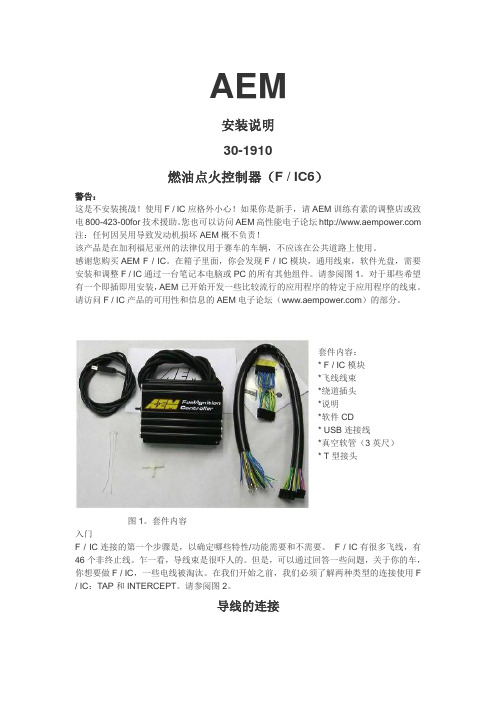
套件内容:* F / IC模块*飞线线束*绕道插头*说明*软件CD* USB连接线*真空软管(3英尺)* T型接头图1。
套件内容入门F / IC连接的第一个步骤是,以确定哪些特性/功能需要和不需要。
F / IC有很多飞线,有46个非终止线。
乍一看,导线束是很吓人的。
但是,可以通过回答一些问题,关于你的车,你想要做F / IC,一些电线被淘汰。
在我们开始之前,我们必须了解两种类型的连接使用F / IC:TAP和INTERCEPT。
请参阅图2。
导线的连接图2。
线的连接INTERCEPT截取TAP塞子TO ENGINE 引擎CUT WIRE 剪断线您的车辆是否有一个的MAG或霍尔式曲轴传感器?MAG式传感器通常有两条线。
霍尔式传感器通常有三根线。
车辆只能有一个MAG或一个霍尔式曲轴传感器。
如果您的车辆有一个MAG传感器,霍尔传感器曲轴线被淘汰。
如果您的车辆有霍尔传感器则MAG感应线被淘汰。
如下面在图3中示出的曲轴传感器连接。
霍尔式曲轴CONNECTIOSENSOR传感器SIGNAL信号MAG式曲轴连接图3。
曲轴传感器连接您的车辆有一个还是两个凸轮传感器?如果你的车有一个凸轮传感器,两个“CAM2”霍尔线和四个”CAM2” MAG线被淘汰。
最新AE(Advanced Energy)直流电源汇总
●更高的沉积率与产品率
●薄膜均匀性和品质一流
●成弧造成的基材损坏减少
●成本更低
●系统整合容易
●极佳的工艺灵活性和宽容度
●重复性能
●在过度曲线上运行稳定
●吞吐量更高
●便于监控
●无与伦比的系统灵活性
特点:
●一个紧凑型封装
●频率调节范围为5-350kHz
●占空比高达45%
●电压范围宽——单输出宽阻抗范围
vm0415awvm0450wicpvm1000avm1500awvm1500wicpvm2715awvm5000w10tvm5000w2tvm5000w4tvm5000w6tvm5000w8tvm5000wicpvm600a存在着赛车手从四川省网得分vrgr存在着赛车手从四川省网得分vrgr存在着赛车手从四川省网得分vrgr存在着赛车手从四川省网得分vrgr存在着赛车手从四川省网得分vrgr存在着赛车手从四川省网得分vrgr存在着赛车手从四川省网得分vrgr存在着赛车手从四川省网得分vrgr存在着赛车手从四川省网得分vrgr存在着赛车手从四川省网得分vrgr存在着赛车手从四川省网得分vrgr存在着赛车手从四川省网得分vrgr存在着赛车手从四川省网得分vrgr存在着赛车手从四川省网得分vrgr存在着赛车手从四川省网得分vrgr存在着赛车手从四川省网得分vrgr存在着赛车手从四川省网得分vrgr存在着赛车手从四川省网得分vrgr存在着赛车手从四川省网得分vrgr存在着赛车手从四川省网得分vrgr存在着赛车手从四川省网得分vrgr存在着赛车手从四川省网得分vrgr存在着赛车手从四川省网得分vrgr存在着赛车手从四川省网得分vrgr存在着赛车手从四川省网得分vrgr存在着赛车手从四川省网得分vrgr存在着赛车手从四川省网得分vrgr存在着赛车手从四川省网得分vrgr存在着赛车手从四川省网得分vrgr存在着赛车手从四川省网得分vrgr存在着赛车手从四川省网得分vrgr存在着赛车手从四川省网得分vrgr存在着赛车手从四川省网得分vrgr存在着赛车手从四川省网得分vrgr存在着赛车手从四川省网得分vrgr存在着赛车手从四川省网得分vrgr存在着赛车手从四川省网得分vrgr存在着赛车手从四川省网得分vrgr存在着赛车手从四川省网得分vrgr存在着赛车手从四川省网得分vrgr存在着赛车手从四川省网得分vrgr存在着赛车手从四川省网得分vrgr存在着赛车手从四川省网得分vrgr存在着赛车手从四川省网得分vrgr存在着赛车手从四川省网得分vrgr存在着赛车手从四川省网得分vrgr存在着赛车手从四川省网得分vrgr存在着赛车手从四川省网得分vrgr存在着赛车手从四川省网得分vrgr存在着赛车手从四川省网得分vrgr存在着赛车手从四川省网得分vrgr存在着赛车手从四川省网得分vrgr存在着赛车手从四川省网得分vrgr存在着赛车手从四川省
- 1、下载文档前请自行甄别文档内容的完整性,平台不提供额外的编辑、内容补充、找答案等附加服务。
- 2、"仅部分预览"的文档,不可在线预览部分如存在完整性等问题,可反馈申请退款(可完整预览的文档不适用该条件!)。
- 3、如文档侵犯您的权益,请联系客服反馈,我们会尽快为您处理(人工客服工作时间:9:00-18:30)。
Features• Eight Pairs of Differential Clocks • Low skew < 50ps• Low Cycle-to-cycle jitter < 50ps • Output Enable for all outputs • Outputs Tristate control via SMBus • Power Management Control • Programmable PLL Bandwidth • PLL or Fanout operation • 3.3V Operation• Packaging (Pb-Free & Green):— 48-Pin SSOP (V) — 48-Pin TSSOP (A)DescriptionPI6C20800 is a high-speed, low-noise differential clock buffer designed to be a companion to PI6C410B. The device distributes the differential SRC clock from PI6C410B to eight differential pairs of clock outputs either with or without PLL. The input SRC clock can be divided by 2 when SRC_DIV# is LOW. The clock outputs are controlled by input selection of SRC_STOP#, PWRDWN# and SMBus, SCLK and SDA. When input of either SRC_STOP# or PWRDWN# is LOW, the output clocks are Tristated. When PWRDWN# is LOW, the SDA and SCLK inputs must be Tristated.PCI Express ChipsetsPin ConfigurationV DD_A V SS_A I REF LOCK OE_7OE_4OUT7OUT7#OE_INV V DD OUT6OUT6#OE_6OE_5OUT5OUT5#V SS V DD OUT4OUT4#PLL_BW#SRC_STOP PWRDWN# V SS484746454443424140393837363534333231302928272625123456789101112131415161718192021222324SRC_DIV#V DD V SS SRC SRC#OE_0OE_3OUT0OUT0#VSS V DD OUT1OUT1#OE_1OE_2OUT2OUT2#V SS V DD OUT3OUT3#PLL/BYPASS#SCLK SDAPI6C208001:8 Clock Driver for IntelPCI Express ChipsetsPin DescriptionsPin Name Type Pin #DescriptionsSRC_DIV#Input1 3.3V LVTTL input for selecting input frequency divide by 2,active LOW.SRC & SRC#Input4, 50.7V Differential SRC input from PI6C410 clock synthesizerOE [0:7]Input6, 7, 14, 15, 35, 36,43, 44 3.3V LVTTL input for enabling outputs, active HIGH.OE_INV Input403.3V LVTTL input for inverting the OE, SRC_STOP# and PWRDWN# pins.When 0 = same stageWhen 1 = OE[0:7], SRC_STOP#, PWRDWN# inverted.OUT[0:7] & OUT[0:7]#Output8, 9, 12, 13, 16 17,20, 21, 29, 30, 33, 34,37, 38, 41, 420.7V Differential outputsPLL/BYPASS#Input22 3.3V LVTTL input for selecting fan-out of PLL operation. SCLK Input23SMBus compatible SCLOCK inputSDA I/O24SMBus compatible SDATAI REF Input46External resistor connection to set the differential output current SRC_STOP#Input27 3.3V LVTTL input for SRC stop, active LOWPLL_BW#Input28 3.3V LVTTL input for selecting the PLL bandwidth PWRDWN# Input26 3.3V LVTTL input for Power Down operation, active LOW LOCK Output45 3.3V LVTTL output, transition high when PLL lock is achieved(Latched output)V DD Power2, 11, 19, 31, 39 3.3V Power Supply for OutputsV SS Ground3, 10, 18, 25, 32Ground for OutputsV SS_A Ground47Ground for PLLV DD_A Power48 3.3V Power Supply for PLLSerial Data Interface (SMBus)PI6C20800 is a slave only SMBus device that supports indexed block read and indexed block write protocol using a single 7-bit address and read/write bit as shown below.Address assignmentA6A5A4A3A2A1A0R/W 11011100/1 Data Protocol(1)1 bit7 bits118 bits18 bits18 bits18 bits1 1 bitStart bit SlaveAddr R/W AckRegisteroffset AckByteCount= NAck DataByte 0AckDataByte N- 1Ack StopbitNote:1. Register offset for indicating the starting register for indexed block write and indexed block read. Byte Count in write mode cannot be 0.PI6C208001:8 Clock Driver for IntelPCI Express ChipsetsData Byte 0: Control RegisterBit DescriptionsType Power Up ConditionOutput(s) Affected Pin 0SRC_DIV#0 = Divide by 21 = Normal RW1 = x1OUT[0:7], OUT[0:7]#NA1PLL/BYPASS#0 = Fanout 1 = PLLRW 1 = PLL OUT[0:7], OUT[0:7]#NA2PLL Bandwidth0 = HIGH Bandwidth,1 = LOW Bandwidth RW 1 = Low OUT[0:7], OUT[0:7]#NA 3TBD NA 4TBD NA 5TBDNA6SRC_STOP#0 = Driven when stopped 1 = TristateRW0 = Driven when stoppedOUT[0:7], OUT[0:7]#7PWRDWN#0 = Driven when stopped 1 = TristateRW 0 = Driven when stopped OUT[0:7], OUT[0:7]#NAData Byte 1: Control RegisterBit DescriptionsType Power Up ConditionOutput(s) Affected Pin 0OUTPUTS enable 1 = Enabled 0 = Disabled RW 1 = Enabled OUT0, OUT0#NA 1RW 1 = Enabled OUT1, OUT1#NA 2RW 1 = Enabled OUT2, OUT2#NA 3RW 1 = Enabled OUT3, OUT3#NA 4RW 1 = Enabled OUT4, OUT4#NA 5RW 1 = Enabled OUT5, OUT5#NA 6RW 1 = Enabled OUT6, OUT6#NA 7RW1 = EnabledOUT7, OUT7#NAPI6C208001:8 Clock Driver for IntelPCI Express ChipsetsData Byte 2: Control RegisterBit DescriptionsType Power Up Condition Output(s) Affected Pin 0Allow control of OUTPUTS with assertion of SRC_STOP#0 = Free running1 = Stopped with SRC_Stop#RW 0 = Free running OUT0, OUT0#NA 1RW 0 = Free running OUT1, OUT1#NA 2RW 0 = Free running OUT2, OUT2#NA 3RW 0 = Free running OUT3, OUT3#NA 4RW 0 = Free running OUT4, OUT4#NA 5RW 0 = Free running OUT5, OUT5#NA 6RW 0 = Free running OUT6, OUT6#NA 7RW0 = Free runningOUT7, OUT7#NAData Byte 3: Control RegisterBit DescriptionsType Power Up ConditionOutput(s) AffectedPin0TBD RW 1RW 2RW 3RW 4RW 5RW 6RW 7RWData Byte 4: Pericom ID RegisterBit DescriptionsType Power Up ConditionOutput(s) AffectedPin 0Pericom ID R 0NA NA 1R 0NA NA 2R 0NA NA 3R 0NA NA 4R 0NA NA 5R 1NA NA 6R 0NA NA 7RNANAPI6C208001:8 Clock Driver for IntelPCI Express ChipsetsFunctionalityPWRDWN#OUT OUT#SRC_Stop#OUT OUT#1Normal Normal 1Normal Normal 0I REF × 2 or FloatLOWI REF × 6 or FloatLOWFigure 1. Power down sequencePI6C208001:8 Clock Driver for IntelPCI Express ChipsetsDifferential Clock Buffer characteristicsSymbol Minimum Maximum R O 3000ΩN/A R OS unspecified unspecified V OUTN/A850mVCurrent AccuracySymbol Conditions Configuration LoadMin.Max.I OUTV DD = 3.30 ±5%R REF = 475Ω 1%I REF = 2.32mANominal test load for given configuration-12%I NOMINAL +12%I NOMINAL Note:1. I NOMINAL refers to the expected current based on the configuration of the device.Differential Clock Output CurrentBoard Target Trace/Term Z Reference R, Iref = V DD /(3xRr)Output Current V OH @ Z 100Ω(100Ω differential ≈ 15% coupling ratio)R REF = 475Ω 1%, I REF = 2.32mAI OH = 6 x I REF0.7V @ 50PI6C208001:8 Clock Driver for IntelPCI Express ChipsetsAbsolute Maximum Ratings (1) (Over operating free-air temperature range)Symbol ParametersMin.Max.UnitsV DD_A 3.3V Core Supply V oltage -0.5 4.6V V DD 3.3V I/O Supply V oltage -0.54.6V IH Input HIGH V oltage 4.6V IL Input LOW V oltage -0.5 Ts Storage Temperature -65150°C V ESDESD Protection2000VNote:1. Stress beyond those listed under “Absolute Maximum Ratings” may cause permanent damage to the device.DC Electrical Characteristics (V DD = 3.3±5%, V DD_A = 3.3±5%)Symbol Parameters ConditionMin.Max.UnitsV DD_A 3.3V Core Supply V oltage 3.135 3.465V V DD 3.3V I/O Supply V oltage 3.135 3.465V IH 3.3V Input HIGH V oltage V DD 2.0V DD + 0.3V IL 3.3V Input LOW V oltage V SS – 0.30.8I IK Input Leakage Current 0 < V IN < V DD -5+5μA V OH 3.3V Output HIGH V oltage I OH = -1mA 2.4V V OL 3.3V Output LOW V oltage I OL = 1mA 0.4I OH Output HIGH Current I OH = 6 x I REF , I REF = 2.32mA12.2mA 15.6C IN Logic Input Pin Capacitance 1.55pF C OUT Output Pin Capacitance6L PIN Pin Inductance 7nH I DD Power Supply Current V DD = 3.465V , F CPU = 200MHz250mAI SS Power Down Current Driven outputs 60I SS Power Down Current Tristate outputs12T AAmbient Temperature70°CPI6C208001:8 Clock Driver for IntelPCI Express ChipsetsAC Switching Characteristics (1,2,3) (V DD = 3.3±5%, V DD_A = 3.3±5%)Symbol ParametersMin Max.UnitsNotes T rise / T fall Rise and Fall Time (measured between 0.175V to 0.525V)175700ps 2ΔT rise / ΔT fall Rise and Fall Time Variation 1252T skew Output-to-Output Skew 50ps 3V HIGH V oltage HIGH 660850mV2V OVS Max. V oltage 1150V UDS Min. V oltage -300V LOW V oltage LOW-150+1502V cross Absolute crossing poing voltages 2505502ΔV cross Total Variation of V cross over all edges 1402T DC Duty Cycle4555%3T jcyc-cycJitter, Cycle-to-cycle (PLL Mode, Measurement for differential waveform)50psJitter, Cycle-to-cycle (BYPASS mode as additive jitter)Notes:1. Test configuration is R S = 33.2Ω, Rp = 49.9Ω, and 2pF.2. Measurement taken from Single Ended waveform.3. Measurement taken from Differential waveform.Configuration Test Load Board TerminationPI6C208001:8 Clock Driver for IntelPCI Express ChipsetsPackaging Mechanical: 48-Pin TSSOP (A)PI6C208001:8 Clock Driver for IntelPCI Express ChipsetsOrdering Information(1,2)Ordering Code Package Code Package Description PI6C20800VE VE48-pin, 300-mil wide, SSOP, Pb-Free and GreenPI6C20800AE AE48-pin, 240-mil wide, TSSOP, Pb-Free and GreenNotes:1. Thermal characteristics can be found on the company web site at /packaging/2. E = Pb-free and GreenPericom Semiconductor Corporation • 1-800-435-2336 • 。
