princ-ch05-presentation
NEC EXPRESSCLUSTER X 5.1 产品说明书

Version 5.1 New EnhancementNovember 2023NECTechnology Service and Software Department (EXPRESSCLUSTER)EXPRESSCLUSTER RoadmapProviding various platforms with high availability in accordance with the timesEnhancement Points of EXPRESSCLUSTER X 5.1Enhancements for the cloud ⚫Added forced-stop resources for Azure.⚫Mail Report function supports SMTPS and STARTTLS.⚫Facilitated the configuration and operation processes in the cloud environment.Security enhancements⚫Added the function to display operation logs of the Cluster WebUI.⚫Added the function to configure the log storage period.⚫Added the function to configure a floating IP resource as a source IP address.⚫Supported OpenSSL 3.0.Newly supported platforms & applications ⚫SUSE Linux Enterprise Server 15 SP4⚫Ubuntu Server22.04.1 LTS, Ubuntu Server20.04.5 LTS⚫SQL Server2022,PostgreSQL 15.1, MariaDB 8.0.31,MariaDB 10.10⚫ReFSEnhancements for the CloudAdded forced-stop resources for Azure.Mail Report function supports SMTPS and STARTTLS.Facilitated the configuration and operation processes in the cloud environment.Added Forced-stop Resources for AzureThe forced-stop function that prevents both-system activation due to a hang-up has been enhanced: GUI configuration now allows using the function to forcedly stop a failed node before failover.This can be configured from GUI withoutscripting.Availability SetResource GroupVMBlob storageFault Domain 0Fault Domain 1MirroringVMBlob storageForcedly stop a failed node before theoperation startup![Cluster WebUI] ->[Cluster Properties]-> [Fencing]tab-> [Forced Stop] FailureOperationOperation◆Mail Report function is now available for SMTPS/STARTTLS-required email delivery services such as “Email Delivery”, email delivery service on OCI.Mail Report function is now supported on Oracle Cloud Infrastructure (OCI).Oracle Cloud InfrastructureAvailability DomainEmail DeliverySSL(TLS)Internet!System AdministratorFailure*This enhanced function is available in the on-premises environment as well.Mail Report function supports SMTPS and STARTTLSOther Facilitation Improvements in Configuration and Operation on the Cloud Environment◆For configuration◼Environment variables for using AWS-related functions (such as AWS virtual IP resources) now can be configured from the Cluster WebUI. This allows the configuration without going through a proxy to be set on the Cluster WebUI, for example, only when EXPRESSCLUSTER uses AWS-related functions.◼Added the function for specifying a command line option, to the AWS CLI being executed with the AWS-related function. This allows specifying the end point for executing the AWS CLI.◼Installing Python is not needed anymore in the configuration using only the AWS virtual IPresource and the AWS virtual IP monitor resource.◼Installing the VMware vSphere CLI is not needed anymore to use the forced-stop function in the vSphere environment.◆For operation*This enhanced function is available in the on-premises environment as well.◼Added the option not to execute the OS restart, to the backup/restore commands(clpbackup/clprestore). This now allows some procedures to be performed without the OS restart.Security EnhancementsAdded the function to display operation logs of the Cluster WebUI.Added the function to configure the log storage period.Added the function to configure a floating IP resource as a source IP address. Supported OpenSSL 3.0.Added the Function to Display Operation Logs of the Cluster WebUIAdded the tab to display the history of operations performed on the Cluster WebUI: It is now possible to check traces of incorrect or invalid operations.At [2:07:20 am, May 17, 2023], by the user [clpuser2], from the IP address [10.20.10.200], the group [failover] was requested to move to the server [server22].At [2:08:28 am, May 17, 2023], by the user [clpuser1], from the IP address [10.20.10.200], the properties of the group [failover] were viewed.When, by whom, from where, what operation was performed now can be checked on the Cluster WebUI!Added the Function to Configure the Log Storage PeriodItems to configure for the log storage period have been added to the Cluster WebUI: It is now easy to address the requirements for the log storage.Examples of guidelines for the log storage period◆PCI Data Security Standard v4.0 (*1)◼10.5.1 Retain audit log history for at least 12 months , with at least the most recent three months immediately available for analysis.◆Convention on Cybercrime (ETS No. 185) (*2)◼oblige that person to preserve and maintain the integrity of that computer data for a period as long as necessary, up to a maximum of ninety days◆NIST SP 800-92 (Guide to Computer Security Log Management) (*3)◼Table 4-1. Examples of Logging Configuration SettingsLogs can be compressed, stored to the logstorage directory at the specified time such as the one with low server load, and kept for the desired storage period.(*1) https:///document_library/(*2) https://www.coe.int/en/web/conventions/full-list?module=treaty-detail&treatynum=185(*3)https:///nistpubs/legacy/sp/nistspecialpublication800-92.pdf[Cluster WebUI] ->[Cluster Properties]-> [Extension] tab-> [Settings of log storage period]Added the Function to Configure a Floating IP Address as a Source IP Address Items to configure a floating IP address as a source IP address have been added to the Cluster WebUI: The number of ports to be opened in the firewall now can be minimized as needed.◆Before◆The source IP is not fixed. (Actual IP or floating IP)◼If the firewall restricts the source IP address, all the IP addressesneed to be opened.◼If a failover occurs, the source IP address changes, and then theserver communicating with the cluster server behaves in anunexpected way.◆After ◆The source IP is fixed to the floating IP.◼If the firewall restricts the source IP address, only the floating IP address needs to be opened.◼Even if a failover occurs, the source IP address remains unchanged. This allows the server communicating with the cluster server to behave without being aware of the failover.Actual IPs of servers Source IP:10.0.0.10 ?10.0.0.20 ?10.0.0.30 ?Source IP:10.0.0.1010.0.0.2010.0.0.3010.0.0.1010.0.0.2010.0.0.3010.0.0.10Floating IP [Cluster WebUI] -> Properties of Floating IP resource -> [Detail] tab *This function is available also for applications where the clients are aware of the source IPs.Other Security Enhancements◆Supported OpenSSL 3.0◼HTTPS access to the Cluster WebUI◼HTTPS monitoring function by HTTP monitor resource◼FTPS monitoring function by FTP monitor resource◼Mail report function (Communication with the mail server by using SMTPS/STARTTLS)◆Disabled TLS 1.1◼HTTPS access to the Cluster WebUINewly Supported Platforms and ApplicationsNewly Supported Platforms and Applications◆OS◼RedHatEnterprise Linux9.2,9.0,8.8◼MIRACLE LINUX9.2,9.0,8.8◼Oracle Linux9.2,9.0,8.8◼SUSE Linux Enterprise Server 15 SP5/SP4◼Ubuntu Server22.04.1 LTS◼Ubuntu Server20.04.5 LTS◼AlmaLinux OS9.2,9.0,8.8◆Data base◼SQL Server 2022◼PostgreSQL 15.1◼MariaDB 8.0.31◼MariaDB 10.10◆File system◼ReFS◆Java execution environment◼Java17◆Java application◼WebSAM SVF PDF Enterprise 10.1◼WebSAM RDE SUITE 10.1◼WebSAM SVF Connect SUITE Standard 10.1Thank YouAn Integrated High Availability and Disaster Recovery Solution For more product information & request for trial license, visit >>https:///expresscluster/For more information, feel free to contact us -https:///en/global/prod/expresscluster/en/contact.html。
JEC Y 系列承认书(P005)
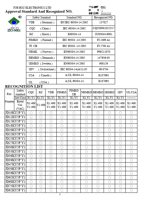
文件編號:P005
INTRODUCTION
版 本:3 制訂日期:2010/12/10
These Ceramic Disc Capacitors are specifically designed for AC applications and meet the
CQC ( China )
IEC 60384-14:2005 CQC08001022317
KC ( Korea )
K60384-14
SU03044-9001
VDE ( Germany ) EN/IEC 60384 -14:2005
137027
FIMKO ( Finland )
IEC 60384 -14:2005
X1
Y1
400 VAC
SEMKO, SEV, FIMKO,
400 VAC
400 VAC
NEMKO, DEMKO, VDE (0565 Teil 1-1)
Dielectric Rated Voltage Withstanding Voltage
Dissipation Y5P,Y5U
Test Voltage
10 pF to 4700 pF. measured at 1KHz±10%, 1.0 - 5.0 Vrms, 25℃
( C ) Tolerance
Insulation Resistance Temperature Typ) e Code
±10%
Y5P
±20%
Y5U,Y5V
( I R 10000 MΩ min, 500 VDC
(1) (2) (3) (4) (5)
(2) Rated capacitance
广告与销售

資料庫行銷成功的七個關鍵
建構行銷資料庫 區分潛在顧客、現有顧客與流失顧客 採問題形式建立使用便利的資料搜尋工具 衡量接觸與反應(應答 vs. 回應) 評估顧客的生命週期價值 先推行試驗專案 務必與產品/服務設計部門保持密切關係
資料庫使用所面臨的挑戰
文化的混合與衝突 因顧客資料的取得與控制所產生的衝突 成本與需求的產生 資料庫由誰負責? 軟體的選擇
消費者遭誤導的理由很多,從消費者自己的疏忽到行銷 人員的失誤或刻意欺騙等。
本文主旨就是從企業觀點來思考此類規範,並討論發生 顧客抱怨與申訴時較常見的議題。
當消費者覺得被騙時,多數國家都可訴諸法律途徑解決, 不過透過自律組織(self-regulatory organization; SROs) 可獲得又快又便宜的補償。
銷售團隊整合小組面臨的挑戰
留下最好的人才。 針對每個合併流程做出最佳決策。 儘可能讓合併流程如期完成。 產生合併相關的綜效。
5 監督市場誤導者
肯特•葛瑞森(Kent Grayson)與(Svetlana Kirillova)撰文 本文探討顧客期望以及存在於行銷人員與顧客之間的
溝通問題。
前言
誤導顧客是企業界相當嚴重的事情。
最好的合併必須具備兩項要素,即從零開始與創造價值。
合併後應擷取各組成分子的優點
由於合併前,各個銷售團隊都有自己的部門文化、銷售 流程與支援系統。 合併後的新部門至少應該擷取各組成份子的優點。 最好的策略是將合併視為銷售團隊的創建,並發展比合 併前還要出色的業務部門。
銷售團隊合併很少能立竿見影
過度縮減規模或人力。 容易存在「征服」心理。 資訊未能分享,公司內部溝通減緩。 銷售團隊整合曠日廢時。 重要員工掛冠求去。 由於情勢太過混亂,顧客關係受損 新合併的團隊不及合併之前的團隊優秀
riNEMI-IPC_Standard_RoHS_Composition_Data

ODMs EMSs
OEM
Channel Partners, Customers Distribution
EOL Warranty, Re-use, Repair & Reclaim, Return Recycle
Compliance requires collection of information across the supply chain. Compliance requires collection of information across the supply chain. Managing risk requires establishing supplier liability at each tier. Managing risk requires establishing supplier liability at each tier.
IPC
Draft Standards
Restriction of Hazardous Materials
Complimentary to
Standards model and standardized forms IPC-1752-1, that support both electronic 1752-2, 1751
Provides an electronic data
RoHS
Requires
MCD
exchange and human input
Based on
Material Composition Declaration Form
EIA
WEEE Directive
Requires the collection, treatment, recycling and recovery of waste electrical and electronic equipment
Pepperl+Fuchs SC3,5-G-N0 型号的产品说明书

17-02-16 15:17D a t e o f i s s u e : 2017-02-16045585_e n g .x m lInstructionManual electrical apparatus for hazardous areas Device category 1Gfor use in hazardous areas with gas, vapour and mist EC-T ype Examination CertificateCE marking ATEX marking ¬ II 1G Ex ia IIC T6…T1 G aThe Ex-related marking can also be printed on the enclosed label.Standards EN 60079-0:2012+A11:2013, EN 60079-11:2012 Ignition protection "Intrinsic safety"Use is restricted to the following stated conditions Appropriate typeSC3,5...-N0...Effective internal inductivity C i ≤ 150 nF ; a cable length of 10 m is considered.Effective internal inductance L i≤ 150 µH ; a cable length of 10 m is considered.G eneralThe apparatus has to be operated according to the appropriate data in the data sheet and in this instruction manual. The EU-type examination certificate has to beobserved. The special conditions must be adhered to! The ATEX directive and there-fore the EU-type examination certificates are in general only applicable to the use of electrical apparatus operating at atmospheric conditions. The device has been checked for suitability for use at ambient temperatures of >60°C by the named certification authority. The surface temperature of the device remains within the required limits. If the equipment is not used under atmospheric conditions, a reduc-tion of the permissible minimum ignition energies may have to be taken into consid-eration.Highest permissible ambient temperatureDetails of the correlation between the type of circuit connected, the maximum per-missible ambient temperature, the temperature class, and the effective internal reac-tance values can be found on the EU-type examination certificate. Note: Use the temperature table for category 1 The 20 % reduction in accordance with EN 1127-1 has already been applied to the temperature table for category 1.Installation, commissioningLaws and/or regulations and standards governing the use or intended usage goal must be observed. The intrinsic safety is only assured in connection with an appro-priate related apparatus and according to the proof of intrinsic safety. The associated apparatus must satisfy the requirements of category ia. Because of the risk of igni-tion, which can occur due to faults and/or transient currents in the equipotential bonding system, galvanic isolation is preferable in the supply and signal circuits. Associated apparatus without electrical isolation can only be used if the correspond-ing requirements of IEC 60079-14 are satisfied. Install the device in such a way that the resin surface is not exposed to mechanical hazards. If the Ex-related marking is printed only on the supplied label, then this must be attached in the immediate vicin-ity of the sensor. The sticking surface for the label must be clean and free from grease. The attached label must be legible and indelible, including in the event of possible chemical corrosion.Maintenance No changes can be made to apparatus, which are operated in hazardous areas.Repairs to these apparatus are not possible.Special conditionsThe connecting parts of the sensor must be set up in such a way that degree of pro-tection IP20, in accordance with lEC 60529, is achieved as a minimum.Protection from mechanical dangerWhen using the device in a temperature range of -60 °C to -20 °C, protect the sensor against the effects of impact by installing an additional enclosure. The information regarding the minimum ambient temperature for the sensor as provided in the datasheet must also be observed.R e l e a s e d a t e : 2017-02-16 15:17D a t e o f i s s u e : 2017-02-16045585_e n g .x m lInstructionManual electrical apparatus for hazardous areas Device category 2Gfor use in hazardous areas with gas, vapour and mist EC-T ype Examination CertificateCE marking ATEX marking ¬ II 1G Ex ia IIC T6…T1 G aThe Ex-related marking can also be printed on the enclosed label.Standards EN 60079-0:2012+A11:2013, EN 60079-11:2012 Ignition protection "Intrinsic safety"Use is restricted to the following stated conditions Appropriate typeSC3,5...-N0...Effective internal inductivity C i≤ 150 nF ; a cable length of 10 m is considered.Effective internal inductance L i ≤ 150 µH ; a cable length of 10 m is considered.G eneralThe apparatus has to be operated according to the appropriate data in the data sheet and in this instruction manual. The EU-type examination certificate has to be observed. The special conditions must be adhered to!Maximum permissible ambient temperature T amb Details of the correlation between the type of circuit connected, the maximum per-missible ambient temperature, the temperature class, and the effective internal reac-tance values can be found on the EU-type examination certificate.Installation, commissioningLaws and/or regulations and standards governing the use or intended usage goal must be observed. The intrinsic safety is only assured in connection with an appro-priate related apparatus and according to the proof of intrinsic safety. Install the device in such a way that the resin surface is not exposed to mechanical hazards. If the Ex-related marking is printed only on the supplied label, then this must be attached in the immediate vicinity of the sensor. The sticking surface for the label must be clean and free from grease. The attached label must be legible and indeli-ble, including in the event of possible chemical corrosion.Maintenance No changes can be made to apparatus, which are operated in hazardous areas.Repairs to these apparatus are not possible.Special conditionsThe connecting parts of the sensor must be set up in such a way that degree of pro-tection IP20, in accordance with lEC 60529, is achieved as a minimum.Protection from mechanical dangerWhen using the device in a temperature range of -60 °C to -20 °C, protect the sensor against the effects of impact by installing an additional enclosure. The information regarding the minimum ambient temperature for the sensor as provided in the datasheet must also be observed.17-02-16 15:17D a t e o f i s s u e : 2017-02-16045585_e n g .x m lNote This instruction is only valid for products according to EN 60079-15:2003, valid until 31-May-2008InstructionManual electrical apparatus for hazardous areas Device category 3G (nL)CE marking ATEX marking ¬ II 3G EEx nL IIC T6 XStandard conformityEN 60079-15:2003 Ignition protection category "n"Use is restricted to the following stated conditions Effective internal capacitance C i ≤ 150 nF ; a cable length of 10 m is considered.Effective internal inductance L i≤ 150 µH ; a cable length of 10 m is considered.G eneralThe apparatus has to be operated according to the appropriate data in the data sheet and in this instruction manual. The data stated in the data sheet are restricted by this operating instruction! The special conditions must be observed!Installation, commissioningLaws and/or regulations and standards governing the use or intended usage goal must be observed. The sensor must only be operated with an energy-limited circuit, which satisfies the requirements of IEC 60079-15. The explosion group complies with the connected, supplying, power limiting circuit.Maintenance No changes can be made to apparatus, which are operated in hazardous areas.Repairs to these apparatus are not possible.Special conditionsfor Pi=34 mW, Ii=25 mA, T6 66 °C (150.8 °F) for Pi=34 mW, Ii=25 mA, T5 81 °C (177.8 °F) for Pi=34 mW, Ii=25 mA, T4-T1 100 °C (212 °F) for Pi=64 mW, Ii=25 mA, T6 66 °C (150.8 °F) for Pi=64 mW, Ii=25 mA, T5 81 °C (177.8 °F) for Pi=64 mW, Ii=25 mA, T4-T1 100 °C (212 °F) for Pi=169 mW, Ii=52 mA, T6 45 °C (113 °F) for Pi=169 mW, Ii=52 mA, T5 60 °C (140 °F) for Pi=169 mW, Ii=52 mA, T4-T1 89 °C (192.2 °F) for Pi=242 mW, Ii=76 mA, T6 30 °C (86 °F) for Pi=242 mW, Ii=76 mA, T5 45 °C (113 °F) for Pi=242 mW, Ii=76 mA, T4-T1 74 °C (165.2 °F)Protection from mechanical dangerThe sensor must not be mechanically damaged.When used in the temperature range below -20 °C the sensor should be protected from knocks by the provision of an additional housing.Connection partsThe connection parts are to be installed, such that a minimum protection class of IP20 is achieved, in accordance with IEC 60529.R e l e a s e d a t e : 2017-02-16 15:17D a t e o f i s s u e : 2017-02-16045585_e n g .x m lInstructionManual electrical apparatus for hazardous areas Device category 3G (ic) for use in hazardous areas with gas, vapour and mist CertificateCE marking ATEX marking ¬ II 3G Ex ic IIC T6…T1 GcThe Ex-significant identification is on the enclosed adhesive labelStandardsEN 60079-0:2012+A11:2013, EN 60079-11:2012 Ignition protection category "ic" Use is restricted to the following stated conditions Effective internal inductivity C i≤ 150 nF ; a cable length of 10 m is considered.Effective internal inductance L i≤ 150 µH ; a cable length of 10 m is considered.G eneralThe apparatus has to be operated according to the appropriate data in the data sheet and in this instruction manual. The data stated in the data sheet are restricted by this operating instruction! The special conditions must be observed! The ATEX directive generally applies only to the use of electrical apparatus under atmospheric condi-tions. When using the apparatus outside atmospheric conditions, a reduction in the permissible ignition energy must be taken into account where appropriate.Installation, commissioningLaws and/or regulations and standards governing the use or intended usage goal must be observed. The sensor must only be operated with energy-limited circuits, which satisfy the requirements of IEC 60079-11. The explosion group complies with the connected, supplying, power limiting circuit. Install the device in such a way that the resin surface is not exposed to mechanical hazards. If the Ex-relevant identifica-tion is printed exclusively on the adhesive label provided, this label must be affixed in the immediate vicinity of the sensor! The background surface to which the adhesive-label is to be applied must be clean and free from grease! The applied label must be durable and remain legible, with due consideration of the possibility of chemical cor-rosion!Maintenance No changes can be made to apparatus, which are operated in hazardous areas.Repairs to these apparatus are not possible.Special conditionsfor Pi=34 mW, Ii=25 mA, T6 66 °C (150.8 °F) for Pi=34 mW, Ii=25 mA, T5 81 °C (177.8 °F) for Pi=34 mW, Ii=25 mA, T4-T1 100 °C (212 °F) for Pi=64 mW, Ii=25 mA, T6 66 °C (150.8 °F) for Pi=64 mW, Ii=25 mA, T5 81 °C (177.8 °F) for Pi=64 mW, Ii=25 mA, T4-T1 100 °C (212 °F) for Pi=169 mW, Ii=52 mA, T6 45 °C (113 °F) for Pi=169 mW, Ii=52 mA, T5 60 °C (140 °F) for Pi=169 mW, Ii=52 mA, T4-T1 89 °C (192.2 °F) for Pi=242 mW, Ii=76 mA, T6 30 °C (86 °F) for Pi=242 mW, Ii=76 mA, T5 45 °C (113 °F) for Pi=242 mW, Ii=76 mA, T4-T1 74 °C (165.2 °F)Protection from mechanical danger The sensor must not be mechanically damaged.When used in the temperature range below -20 °C the sensor should be protected from knocks by the provision of an additional housing.Connection partsThe connection parts are to be installed, such that a minimum protection class of IP20 is achieved, in accordance with IEC 60529.17-02-16 15:17D a t e o f i s s u e : 2017-02-16045585_e n g .x m lInstructionManual electrical apparatus for hazardous areas Device category 1Dfor use in hazardous areas with combustible dust EC-T ype Examination CertificateCE marking ATEX marking ¬ II 1D Ex ia IIIC T135°C DaThe Ex-related marking can also be printed on the enclosed label.Standards EN 60079-0:2012+A11:2013, EN 60079-11:2012 Ignition protection "Intrinsic safety"Use is restricted to the following stated conditions Appropriate typeSC3,5...-N0...Effective internal inductivity C i ≤ 150 nF ; a cable length of 10 m is considered.Effective internal inductance L i≤ 150 µH ; a cable length of 10 m is considered.G eneralThe apparatus has to be operated according to the appropriate data in the data sheet and in this instruction manual. The EU-type examination certificate has to beobserved. The ATEX Directive and therefore the EU-type-examination certificates generally apply only to the use of electrical apparatus under atmospheric conditions. The device has been checked for suitability for use at ambient temperatures of > 60 °C by the named certification authority. For the use of apparatus outside of atmo-spheric conditions, a reduction of the permissible minimum ignition energies may need to be considered.Highest permissible ambient temperature T ambDetails of the correlation between the type of circuit connected, the maximum per-missible ambient temperature, the surface temperature, and the effective internal reactance values can be found on the EU-type-examination certificate. The maxi-mum permissible ambient temperature of the data sheet must be noted, in addition, the lower of the two values must be maintained.Installation, commissioningLaws and/or regulations and standards governing the use or intended usage goal must be observed. The intrinsic safety is only assured in connection with an appro-priate related apparatus and according to the proof of intrinsic safety. Install the device in such a way that the resin surface is not exposed to mechanical hazards. If the Ex-related marking is printed only on the supplied label, then this must be attached in the immediate vicinity of the sensor. The sticking surface for the label must be clean and free from grease. The attached label must be legible and indeli-ble, including in the event of possible chemical corrosion.Maintenance No changes can be made to apparatus, which are operated in hazardous areas.Repairs to these apparatus are not possible.Special conditionsThe connecting parts of the sensor must be set up in such a way that degree of pro-tection IP20, in accordance with lEC 60529, is achieved as a minimum.Protection from mechanical dangerWhen using the device in a temperature range of -60 °C to -20 °C, protect the sensor against the effects of impact by installing an additional enclosure. The information regarding the minimum ambient temperature for the sensor as provided in the datasheet must also be observed.Electrostatic chargeAvoid electrostatic charges that can cause electrostatic discharge when installing or operating the device. Information on electrostatic hazards can be found in the techni-cal specification IEC/TS 60079-32-1. Do not attach the nameplate provided in areas where electrostatic charge can build up.。
Terminator 5′-Phosphate-Dependent Exonuclease 产品说明

ManualTerminator 5′-Phosphate-Dependent ExonucleaseF or Research Use Only. Not for use in diagnostic procedures.Contents1. Introduction (3)2. Product designations and kit components (3)3. Product specifications (3)4. General considerations (3)5. Standard procedure (5)6. Alternative procedure (5)7. Further support (7)1. IntroductionTerminator 5′-Phosphate-Dependent Exonuclease is a processive 5′→3′ exonuclease that digests RNA having a 5′ monophosphate. It does not digest RNA having a 5′-triphosphate, 5′-cap or 5′-hydroxyl group. These enzymatic properties make Terminator Exonuclease ideal for producing mRNA-enriched samples from both eukaryotic and prokaryotic total RNA preparations by selectively digesting the ribosomal RNA (rRNA).Terminator Exonuclease can be used to isolate eukaryotic mRNA substantially free of 18S and 28S rRNA without using an oligo(dT) matrix. Further, Terminator Exonuclease provides a simple andeffective method for purifying unprocessed, primary bacterial transcripts by removing large rRNA and other processed transcripts.Terminator Exonuclease will also digest single-stranded DNA (ssDNA) having a 5′-phosphate group. It does not digest ssDNA or dsDNA having a 5′-triphosphate or a 5′-hydroxyl group. Terminator Exonuclease is not inhibited by RNase inhibitors such as RNasin (Promega Corporation), Prime RNase Inhibitor (Eppendorf AG) or RiboGuard™ RNase Inhibitor.Terminator 5′-Phosphate-Dependent Exonuclease is available in a 40 unit size at a concentration of 1 U/µL. Two different Terminator 10X Reaction Buffers are also provided with the enzyme, each optimised for different applications.2. Product designations and kit componentsProductKit size Reagent description Catalogue number Part number Volume 3. Product specificationsStorage: Store only at -20 °C in a freezer without a defrost cycle.Storage buffer: Terminator Exonuclease is supplied in a 50% glycerol solution containing 50 mM Tris-HCl (pH 7.5), 0.1 M NaCl, 0.1 mM EDTA, 1 mM dithiothreitol and 0.1% Triton X-100.Unit definition: One unit digests 1 μg of rRNA substrate into acid-soluble nucleotides in 60 minutes at 30 °C under standard assay conditions.Quality control: Terminator Exonuclease is function-tested in a 50 µL reaction containing 50 mM Tris-HCl (pH 8.0), 2 mM MgCl 2, 100 mM NaCl, 20 μg rRNA and varying amounts of enzyme.Contaminating activity assays: Terminator Exonuclease is free of detectable contaminating endonuclease and non-5′-phosphate-dependent nuclease activities.4. General considerationsIntegrity of the RNA sample: The success of a Terminator Exonuclease reaction is strongly influenced by the quality of the total RNA sample used in the reaction. Therefore, it is important to confirm the purity and integrity of the RNA sample prior to beginning the reaction.RNA sample: The RNA sample to be treated with Terminator Exonuclease should be dissolved in RNase-free water prior to treatment.IMPORTANT: Do not dissolve the RNA sample in TE buffer (10 mM Tris-HCl [pH 7.5], 1 mM EDTA) or any other EDTA-containing buffer. EDTA concentrations as low as 1 mM will inhibit Terminator Exonuclease activity.Maintaining an RNase-free environment: Ribonuclease contamination is a significant concern for those working with RNA. The ubiquitous RNase A is a highly stable and active ribonuclease that can contaminate any lab environment and is present on human skin.Creating an RNase-free work environment and maintaining RNase-free solutions is critical for performing successful reactions. Therefore, we strongly recommend that the user:1) Autoclave all tubes and pipette tips that will be used in the reactions.2) Always wear gloves when handling samples containing RNA. Change gloves frequently especiallyafter touching potential sources of RNase contamination such as door knobs, pens, pencils and human skin.3) Always wear gloves when handling reaction components. Do not pick up the enzyme or buffer withan ungloved hand.4) Keep all components tightly sealed when not in use. Keep all tubes containing RNA tightly sealedduring the incubation steps.Buffer/protocol choice: Terminator 5′-Phosphate-Dependent Exonuclease is a processive 5′→3′ exonuclease that digests RNA that has a 5′ monophosphate. It does not digest RNA that has a5′-triphosphate, 5′-cap or 5′-hydroxyl group. However, on rare occasions, we have observed a secondary, non-5′-monophosphate-specific activity on 5′-triphosphate and 5′-hydroxyl RNAs. Because of this activity, two different 10X Reaction Buffers are provided with this kit. The Terminator 10X Reaction Buffer A and its affiliated protocol constitute the standard buffer and protocol. They have been optimised for maximum 5′-monophosphate RNA digestion (e.g., rRNA digestion). The Terminator 10X Reaction Buffer B and its affiliated protocol are provided as an alternate method that should only be used in the rare event that a specific RNA of interest is being degraded by a secondary non-5′-monophosphate-specific activity. Note, however, that less rRNA will be degraded with this buffer and protocol.NOTE: For best digestion, total input RNA must be of high quality (RNA Integrity Number of at least 8 when evaluated on an Agilent Bioanalyzer Model 2100).NOTE: Using the two different buffers in a 50:50 ratio will not produce a reaction condition with the benefits of each individual buffer and protocol.5. Standard procedureIMPORTANT: Two different reaction buffers and protocols are included with Terminator Exonuclease. Be sure to read Buffer/Protocol Choice (section above) to determine which protocol is appropriate for your intended use. Use one or the other. Do not mix buffers.This protocol uses the Terminator 10X Reaction Buffer A and has been optimised for maximum5′-monophosphate rRNA digestion (e.g., rRNA digestion). Buffer B may be used for very low-mass RNA samples.The RNA sample to be treated should be dissolved in RNase-free water. Do not dissolve the RNA sample in TE buffer.1. Gently mix and briefly centrifuge the Terminator 10X Reaction Buffer A prior to use.2. In a sterile (RNase-free) 0.2 mL or 0.5 mL tube, combine the following reaction components on ice:x μL RNase-free water2 µL Terminator 10X Reaction Buffer A0.5 µL RiboGuard RNase Inhibitory µL Total RNA Sample (200 ng-10 μg)1 μL Terminator Exonuclease (1 unit)20 μL Total reaction volume3. Incubate the reaction at 30 °C for 60 minutes in a thermocycler (with heated lid) or Water bath.4. Terminate the reaction by one of the two methods described in Section 6, Step 4.6. Alternative procedureIMPORTANT: Two different reaction buffers and protocols are included with Terminator Exonuclease. Be sure to read Buffer/Protocol Choice (section above) to determine which protocol is appropriate for your intended use.This protocol uses the Terminator 10X Reaction Buffer B and should only be used in the rare event that a specific RNA of interest is being degraded by a secondary non-5′-monophosphate-specific activity of the enzyme.NOTE: Less rRNA will be degraded with this buffer and protocol.The RNA sample to be treated should be dissolved in RNase-free Water. Do not dissolve the RNA sample in TE buffer.1. Gently mix and briefly centrifuge the Terminator 10X Reaction Buffer B prior to use.2. In a sterile (RNase-free) 0.2-mL or 0.5-mL tube, combine the following reaction components on ice:x μL RNase-free water2 µL Terminator 10X Reaction Buffer B0.5 µL RiboGuard RNase Inhibitory Total RNA Sample (1-2.5 μg)1 μL Terminator Exonuclease (1 unit)20 μL Total reaction volume3. Incubate the reaction at 42 °C for 30 minutes in a thermocycler (With heated lid) or Water bath.4. Terminate the reaction by one of the two methods described below:4a. Terminate the reaction by adding 1 µL of 100 mM EDTA (pH 8.0).Place the reaction on ice. Note that the enriched mRNA sample will now contain 5 mM EDTA (as well as tRNA, nucleotides and other small RNAs). It may be used directly for applications in which the EDTA will not be inhibitory. However, the high concentration of EDTA may interfere with some subsequent uses of the mRNA, such as RT-PCR. Therefore, it may be necessary to remove the excess EDTA by LiCl precipitation (see beloW), ethanol precipitation or use of anRNA purification column.4b. Terminate the reaction by phenol extraction and ethanol precipitation.1. Add RNase-free water to the reaction to a total volume of 200 µL. Extract once withbuffer-saturated phenol.2. Transfer the aqueous phase to a new RNase-free tube.3. Add 0.1 volume of 3 M sodium acetate and 2.5 volumes of ethanol to the aqueous phaseand mix thoroughly.4. Incubate on ice or at -20 °C for 30 minutes.5. Pellet the RNA by centrifugation in a microcentrifuge for 30 minutes at full speed at 4 °C.6. Carefully remove and discard the supernatant. Do not disturb the RNA pellet which containsthe mRNA.7. Wash the RNA pellet with 70% ethanol to remove residual salt. Resuspend the RNA pellet inRNase-free water or TE buffer.5. (Optional) Purify the enriched mRNA. If desired, the enriched mRNA can be purified from excessEDTA, tRNA, 5S rRNA and other small RNA species, by LiCl precipitation or by using a commercial RNA purification column.Lithium chloride precipitation should be performed only if the original reaction contains >2 μg of total RNA. If the amount of total RNA in the reaction was less than 2 μg, purify the mRNA by phenol extraction and ethanol precipitation as described above or using a commercial RNA purification column.Lithium chloride selectively precipitates large RNA such as mRNA, while small RNA such as tRNA1. Add 1 volume of 5 M LiCl solution to the sample and mix well.2. Incubate on ice or at -20 °C for 30 minutes.3. Pellet the RNA in a microcentrifuge for 30 minutes at full speed at 4 °C.4. Carefully remove and discard the supernatant Which contains the tRNA, other small RNAs andnucleotides. Do not disturb the RNA pellet which contains the mRNA.5. Wash the RNA pellet with 70% ethanol to remove residual salt.6. Resuspend the RNA pellet in RNase-free Water or TE buffer.7. (Optional) Analyse the effectiveness of the Terminator reaction by denaturing agarose gelelectrophoresis or using an Agilent 2100 Bioanalyzer. When using either method, it is important to run an untreated RNA sample (~250 ng of total RNA) alongside the treated sample. Theabsence of 18S and 28S rRNA in the post-treatment sample indicates a successful reaction.7. Further supportIf you require any further support, please do not hesitate to contact our Technical Support Team:************************.All trademarks and registered trademarks mentioned herein are the property of their respective owners. All other trademarks and registered trademarks are the property of LGC and its subsidiaries. Specifications, terms and pricing are subject to change. Not all products are available in all countries. Please consult your local sales representative for details. No part of this publication may be reproduced or transmitted in any form or by any means, electronic or mechanical, including photocopying, recording or any retrieval system, without the written permission of the copyright holder. © LGC Limited, 2023. All rights reserved. GEN/894/EK/0223@LGCBiosearch。
PT作业指导书
液体渗透检验作业指导书1.0 范围本程序详细规定了目视液体渗透检验的要求2.0 参考文件如果客户未要求版本,所有标准文件都参照最新发布的版本和附录。
EN 571-1: Non-destructive Testing - Penetrant Testing - Part 1: General PrinciplesEN 473: Non-destructive Testing - Qualification and Certification of NDT PersonnelISO 3059: Non-destructive Testing - Penetrant Testing and Magnetic Particle Testing - Viewing ConditionsISO 9712: Non-destructive testing – Qualification and certification of NDT personnelASME Boiler and Pressure Vessel Code Section V Article 6 - Liquid Penetrant ExaminationASNT Recommended Practice SNT-TC-1A; Personnel Qualification and Certification in Nondestructive Testing3.0 检验人员资质检测人员必须获得EN 473,ISO 9712,SNT-TC-1A或国家认可的等效PTI级的人员只有在PTII级或以上资质人员的监督下才可进行渗透探伤检测。
只有通过II级或III级或国家认可的等效的资格鉴定和认证的人员方可对检测I级人员检测结果进行阐释和评定,监督人员和检测人员都需要在无损报告上签字。
所有的资格和认证必须充分遵守至少一个第 2 节引用的标准本文件,如适用,应完全符合本项目质量计划(检验与试验计划)。
Age-dependent changes in post-crack performance of fibre reinforced shotcrete linings
Age-dependent changes in post-crack performance of fibre reinforced shotcreteliningsErik Stefan Bernard ⇑TSE Pty Ltd,PO Box 763,Penrith,NSW 2750,Australiaa r t i c l e i n f o Article history:Received 30December 2014Received in revised form 12April 2015Accepted 8May 2015Available online 22May 2015Keywords:Post-crack performance Fibre reinforced shotcrete Macro-synthetic fibres Steel fibresTime-dependent behavioura b s t r a c tIt is commonly assumed that when a mix achieves satisfactory performance in Quality Control tests at 28days this result will translate into satisfactory performance throughout the design life of the corre-sponding concrete structure.While this is generally true of the compressive strength of concrete it is not necessarily true for other parameters.The post-crack performance of fibre reinforced concrete (FRC)differs from that of conventionally reinforced concrete in that the post-crack performance of fibres is related in a complex manner to the characteristics of the concrete matrix.Age-dependent changes in the characteristics of the concrete matrix can effect changes in the post-crack behaviour of fibres.The present investigation has examined how the post-crack energy absorption of fibre reinforced shotcrete (FRS)changes with aging and has found that some types of fibre exhibit dramatically different perfor-mance characteristics at late age compared to that displayed at 28days.This change can have significant consequences for the design of ground support based on fibre reinforced shotcrete.Tunnel linings required to resist sustained ground stresses,or which may be subject to deformation associated with seismicity or ground movement at later ages,should be designed with consideration of a possible long-term loss of ductility exhibited by some types of fibre reinforced shotcrete.Ó2015The Author.Published by Elsevier Ltd.This is an open access article under the CC BY license (http:///licenses/by/4.0/).1.IntroductionIn the construction of public infrastructure such as tunnels it has become common to specify a design life of 100+years (Franzen et al.,2001).This places very high demands on shotcrete used for ground stabilisation given the concurrent requirement on this material to be pumped and sprayed without blockages,gain strength rapidly,and then remain firmly in place while resisting the effects of environmental exposure.Requirements for resistance to deterioration have generally promoted the use of high binder contents,including pozzolanic additives,and low water/binder ratios leading to low permeability and good chemical inertness.The long-term consequence of this tends to be high strength devel-opment at late ages (Malhorta,1993).Most shotcrete used in underground applications is reinforced with fibres.Unlike conven-tional steel bar reinforcement,the post-crack performance of fibres is strongly influenced by the characteristics of the concrete matrix.Post-crack performance characteristics therefore change with the evolution of strength and hardness of the concrete matrix.The ability of fibre reinforced shotcrete (FRS)to rapidly achieve and then retain ductility (commonly referred to as ‘toughness’)as it ages is generally recognized as being important to the successful use of this material,especially for ground stabilization.This is because ductility is critical to the re-distribution of load when,for example,ground movement causes localized cracking of the concrete matrix within a shotcrete lining.If ductility diminishes with age or exposure to aggressive agents,then the ability of a structure such as a tunnel lining to maintain stability may be com-promised.This is why minimum levels of ductility are considered mandatory for moment re-distribution requirements in conven-tional above ground structures,made of,for example,reinforced concrete (Beletich et al.,2013;Nielsen,1998)and is also the reason why FRS performance is specified in terms of energy absorption in widely used design approaches to ground stabilization such as the Q-system (Barton and Grimstad,2004).The ability of FRS infras-tructure to achieve and then maintain a high level of energy absorption over the life of a structure can be considered a valid and relevant indicator of fitness-for-purpose and ‘durability’.The vast majority of FRS is used to stabilize excavated ground,particularly hard rock,thus the focus of the present investigation has been the performance of FRS in this application.When FRS is first sprayed on to freshly excavated ground,the ability of the shot-crete to stabilize the ground will initially depend on the adequacy/10.1016/j.tust.2015.05.0060886-7798/Ó2015The Author.Published by Elsevier Ltd.⇑Tel.:+61418407892.E-mail address:s.bernard@.auforcement because macro-fibres(whether made of steel or poly-mers)are largely ineffective over thefirst few hours after spraying(Bernard,2008a).Moreover,most early-age lining failures are governed by punching resistance rather thanflexure andfibres contribute very little to shear resistance in young concrete (Bernard,2011).However,as the shotcrete gains strength the pre-dominant mode of failure changes from shear toflexure and it is at this point that the performance offibre reinforcement becomes important.Fibre reinforcement provides substantial post-crack energy absorption and load re-distribution capacity to a material that is otherwise quite brittle and ineffective in ground control(Bernard,2002;Naaman,1985).It thereby allows a con-crete lining to accommodate a degree of ground movement with-out loss of structural competency.Maintenance of this property is important to the long-term functionality of FRS linings should later-age ground movement occur.2013;Decker et al.,2012),energy absorption is specified on the basis of FRS performance using ASTM C1550round panels (ASTM,2012).ASTM C1550panels have therefore been used to assess FRS performance throughout this investigation.As an indi-cation of performance requirements for underground applications, a minimum energy absorption of400J at40mm central deflection in the ASTM C1550panel test has been found to be adequate for the majority of tunnelling and mining projects(Papworth,2002).Aging of concrete in underground environments normally gives rise to concerns about durability.The ability offibres within uncracked FRS to resist corrosion under conditions of normal atmospheric exposure has been demonstrated through several long-term exposure trials(Schupack,1985;Hara et al.,1992; Mangat and Gurusamy,1985).While carbonation may promote corrosion and loss of structural performance,including ductility, for near-surface steelfibres(Schupack,1985),anyfibres that cor-rode due to proximity to a concrete surface have been shown to exert insufficient expansive pressure to disrupt the enveloping concrete(Hoff,1987;Lankard and Walker,1978).Localized surface corrosion therefore does not develop into structurally-threatening Fig.1.ASTM C1550Load–deflection curves for specimens reinforced with Dramix RC65/35BN in50MPa shotcrete tested at various ages after spraying showing an increase in load resistance at small deflections with aging but a fall in resistance at large deformations.Fig.2.Pulled-out Dramix RC65/35BNfibres on crack face of3day old shotcrete ofthrough-corrosion of the kind that is commonly observed in conventionally-reinforced concrete(Phan et al.,2001).In contrast to the relatively good durability of uncracked FRS, the presence of cracks is recognized as leading to rapid degradation in the performance of FRS when reinforced with steelfibres.Most laboratory andfield tests have shown that exposure of cracked steel FRC surfaces to aggressive environments can degrade post-crack performance(Hoff,1987;Kosa and Naaman,1990; Bernard,2004).Nordström(1999,2001)found that the rate of cor-rosion of steel FRS increased with crack width but that late-age hydration may have the effect of overcoming some of the deterio-ration in performance at small crack widths caused by corrosion ofNordström also noted that negligible corrosion and deterio-occurred for steel FRS exhibiting narrow(<0.1mm) effect of cracking on the performance of macro-synthetic as well documented as for steelfibres,but the complete absence of corrosion and immunity to salt ingress characteristic thesefibres has been noted by several researchers(Bernard, Chernov et al.,2006;Zhang et al.,1999).The advantages failures within the Australian underground mining industry in the1990s.This was one of the contributing factors that drove the industry to adopt macro-synthetic FRS in underground mines throughout Australia(Bernard et al.,2014).As a consequence of the corrosion risk associated with steelfibres,macro-synthetic fibres are mandated as the only acceptable form of reinforcement for subsea tunnel linings in Norway(Concrete for Rock Support, 2011)and now constitute the primary reinforcement in the major-ity of new tunnels recently completed in that country.While durability issues in FRS related to matrix degradation and corrosion have been relatively widely addressed,changes in ductil-ity with aging of intact FRS has only recently entered the con-sciousness of the construction industry.Early studies of the effect of matrix strength onfibre performance(Naaman and Najm, 1991)indicated that resistance to pull-out increased for hooked-end steelfibres as the compressive strength of the con-crete increases.Naaman and Al-Khairi(1996)also noted that the shape of the load–deflection response for hooked-end steel FRC inflexure changed as age increased from one to28days,with load resistance increasing more rapidly at smaller crack widths than at larger crack widths as the concrete aged.A study of the age-dependent behaviour of FRS on the M5 motorway tunnel in Sydney,Australia(Bernard and Hanke,2002) revealed a loss of toughness at late age(termed‘embrittlement’) for shotcrete reinforced with steelfibre.This fall in post-crack per-formance was unrelated to corrosion or any mechanism of deteri-oration in the concrete matrix.Age-dependent changes in post-crack performance were also investigated by Lange and Lee (2003)who examined energy absorption in FRC between one andRuptured Dramix RC65/35BNfibres on crack face offive year old shotcretenominal grade.Fig.4.ASTM C1550Load–deflection curves for specimens reinforced with BarchipBC54in50MPa shotcrete tested at various ages after spraying showing an increaseSpace Technology49(2015)241–2482432.Experimental investigationTo assess the long-term post-crack performance of FRS,a com-prehensive series of trials were conducted involving the produc-tion and testing of ASTM C1550round panels to assess energy absorption between1day and5years age.Eight sets of FRS speci-mens were produced by spraying panels in an inclined position45°to the vertical,and one set of specimens reinforced with SL62steel mesh was produced by casting(see Tables1and2for reinforce-ment and mix data).Thefibres used in the trials were selected on the basis of their widespread use in the underground industry and include35mm Dramix hooked-end steelfibres,30mmNovotexflattened-end steelfibres,48and54mm Barchipembossed macro-syntheticfibres,and50mm Enduro crimpedmacro-syntheticfibres.The specimens comprised ASTMpanels(ASTM,2012)that,if sprayed,included a set acceler-a dosage rate of about4%bwc.Cast cylinders andextracted from concurrently sprayed200mm thick panelsin parallel with the round panels(Australian Standardages at testing were1,2,3,7,14,28,56,91,and180were included,results out to8years were available for some setsat the time of writing.The exposure site was located under a wideviaduct to simulate the entrance of a tunnel.3.ResultsThe results of the investigation comprised load–deflectioncurves obtained for each of the ASTM C-1550panel specimensand UCS data obtained from cores and cast cylinders.An exampleset of load–deflection curves for Dramix RC65/35BN-reinforcedspecimens produced using50MPa shotcrete and continuouslywet cured in the laboratory is shown in Fig.1.These curves revealthat a dramatic change in post-crack performance characteristicsoccurred with increasing age for some of the presently examinedmixes.The hooked-end steel FRS specimens typically exhibited a rela-tively broad load–deflection curve at early-age with substantialpost-crack capacity up to40mm central deflection(equivalent to13mm average maximum crack width(Bernard and Xu,2008).However,as the concrete aged,load resistance increased slightlyat small crack widths but fell substantially at wider crack widthsleading to a dramatic fall in total energy absorption at40mm forthe higher shotcrete strength grades(40and50MPa).By an ageof one year the specimens had lost about70per cent of load capac-ity at a central deflection of5mm(equivalent to an average max-imum crack width of only1.7mm).The steady loss of ductilitywith age experienced by the hooked-end steel FRS appeared tobe related to a change in post-crackfibre behaviour frompull-out to rupture(see Figs.2and3).Pulled-out Barchip BC54fibres on crack face of5year old50MPa shotcrete.Space Technology49(2015)241–248in the degree of surface distress to eachfibre as age increased;this probably indicated an increase in the degree of friction at the fibre-concrete boundary during pull-out.The performance of all the specimens has been summarized interms of energy absorption in the ASTM C1550panel test at5,10,20,and40mm cumulative central deflection.The change in energyabsorption for each specimen set as a function of age is shown inFigs.7–15.For clarity,each set of curves includes actual data pointsfor5and40mm energy absorption,and curve-fits to energyabsorption at5,10,20,and40mm deflection.Curvefitting wasperformed with non-linear functions using a program calledTableCurve2D.The energy absorption data revealed dramatically different pat-terns of post-crack performance for the three types ofreinforcement used.The SL62mesh-reinforced specimens(Set2,Table2)demonstrated a close-to-maximum post-crack perfor-mance capacity within one day of casting and only small changesin energy absorption at40mm with age(Fig.8).This variationmay possibly have been due to discrepancies in the lever armbetween the steel mesh and the concrete compression block inthe concrete.The results obtained for the macro-synthetic FRSspecimen sets indicated a steady increase in performance out to5years with none of these sets(1,7,8,9,see Table1)exhibitinga systematic fall in performance with age(Figs.7and13–15).In contrast to the shotcrete reinforced with macro-syntheticfibres or steel mesh,the hooked-end steel FRS exhibited perfor-mance that was very sensitive to the compressive strength andage of the shotcrete,with optimum post-crack performance occur-ring for concrete with a medium compressive strength(sets3–5inTable1,Figs.9–11).The50MPa mix exhibited near-maximum per-formance over thefirst few days following spraying,after whichperformance at larger deflections fell precipitously as the modeoffibre failure changed from pull-out to rupture.Energy absorp-tion at10and20mm deflection also fell with increasing age.Forthe40MPa mix,the peak in performance occurred around28–56days,while for the25MPa mix the peak performance reacheda plateau around180days age.The shotcrete reinforced withNovotex0730steelfibres also exhibited a peak in performance fol-lowed by a slight fall at later ages,but the sensitivity of this mix toaging was less dramatic than exhibited by the hooked-end steelFRS(Fig.12).Note that none of the FRS mixes used in this investigationexhibited a fall in unconfined compressive strength(UCS)with Fig.9.Energy at5,10,20,and40mm for Dramix RC65/35in50MPa shotcrete.Space Technology49(2015)241–248245performance suffered.Observations offibre failure modes sug-gested that the transition from pull-out to rupture coincided with the progression of compressive strength through the40–45MParegion,but the age at which this occurred differed between mixes.It is suggested that further research is required into the effect ofconcrete matrix properties on the transition from pull-out to rup-ture in post-crack behaviour of hooked-end steelfibres.All the steel FRS mixes exhibited an increase in energy absorp-tion at small deformations with age,while concurrently exhibitingfall in energy absorption at large deformations.This meant thatthe residual load resistance at large deformations was doublydiminished with age(see Fig.1for typical load–deflection curves).In contrast,the macro-synthetic FRS mixes exhibited an initialincrease in energy absorption with compressive strength up toabout40–45MPa after which performance stabilised(Fig.17).Energy absorption between20and40mm deflection in themacro-synthetic FRS panels reached a plateau at40–45MPa andthereafter remained stable.These results suggest thatmacro-syntheticfibres and steel mesh both offer superior perfor-mance in ground stabilisation applications requiring long term duc-tility compared to hooked-end steelfibres.The rupturing of thehooked-end steelfibres at late ages suggests that hooked-end steelfibres(of medium strength grade)offer long-term post-crack per-formance characteristics similar to that of low-ductility steel meshGilbert and Sakka,2007).Fig.12.Energy at5,10,20,and40mm for Novotex0730in40MPa shotcrete.Fig.14.Energy at5,10,20,and40mm for Enduro600in50MPa shotcrete.4.DiscussionThe shotcrete mixes used in thenominal UCS at28days of betweenwidespread inclusion of(SCMs)for reasons of sprayability andresistance,the strength of shotcretebeyond28days.The long-term UCS willgreater than the nominal28dayof the paste continues to increase as theof the strength.The results of thisin-place concrete compressiveat28days can promote a change insome types of steelfibre thatfor performance in lower-strengthhigh energy pull-out mode of failure to ais manifested as a dramatic fall intant to the maintenance of satisfactoryas the maximum strength of materials,with age is a cause for concern.The fall in ductility exhibited by theinvestigation may possibly reduce theredistribute loads should groundThis is of concern because thesethroughout the world for thisment may occur,for example,in thewidening,nearby excavation,or change in groundwater level manyyears after the FRS lining is initially installed.It may also occur as a result of loosening of rocks at joints inflat roof or shallow-arched satisfactory post-crack performance obtained in28day QC speci-mens will automatically translate to similar levels of performance throughout the design life of a structure could lead to serious over-estimates of structural ductility in long-life infrastructure.The evolution of energy absorption over time observed in these trials indicates that performance characteristics appeared to stabi-lize by an age of one year for most of the FRS mixtures examined. For FRS reinforced with macro-syntheticfibres or steel mesh,per-formance simply reached a plateau,but for the steel FRS long-term performance loss was clearly sensitive to the strength of the con-crete matrix.This suggests that when steel FRS is used there is a need to provide proof that the long term performance will not fall relative to the28day result.If long-term performance cannot be guaranteed,a performance reduction factor should be applied to steel FRS to account for the very real possibility that long-term per-formance will be substantially lower than observed at28days.The common minimum energy absorption requirement of400J in the ASTM C1550panel test(equivalent to1000J in the EN14488 square panel(Bernard,2002;BS-EN14488,2006)may therefore have to be higher for steelfibres to account for the possible loss of performance that thesefibres suffer with aging.Based on the present trials,the performance at28days may have to be as much as50%higher for shotcrete reinforced with medium strength steel fibres compared to macro-syntheticfibres if equivalent perfor-mance is to be obtained at late ages.Claims have been made by manufacturers that high strength steelfibres do not suffer perfor-mance loss with age,but this has yet to be verified.5.ConclusionsA clear conclusion from this investigation is that satisfactory post-crack energy absorption observed in QC tests at28days does not guarantee satisfactory performance at later ages,at least for some types of steelfibre reinforced shotcrete.The effects of strength gain and hardening of the cement matrix in aging shot-crete can change the mechanism of failure for some types of steel fibre leading to a loss of post-crack performance at large deforma-Fig.16.Energy at40mm for Dramix RC65/35BN as a function of UCS based on Fig.17.Energy at40mm for macro-synthetic FRS as a function of UCS based on cores.concrete to redistribute loads in response to ground movement.It is therefore necessary to consider the ultimate compressive strength of a shotcrete matrix and its likely long-term effect on the failure mechanism offibres contained in the matrix when assessing the most suitablefibre to use as reinforcement in long life tunnel linings.If steelfibres are used in shotcrete of greater than40MPa nominal grade,post-crack performance requirements in quality control tests at28days may have to be higher than for alternative forms of reinforcement to account for possible falls in performance with aging.AcknowledgementsThe author gratefully acknowledges the Roads and Maritime Service of New South Wales,Transurban Roads Ltd,EPC P/L, Propex Concrete Systems,and Holcim Australia Ltd for their gener-ous support of this investigation.ReferencesFranzen,T.,Garshol,K.F.,Tomisawa,N.,2001.Sprayed concrete forfinal linings:ITA working group report.Tunn.Undergr.Space Technol.16,295–309. Malhorta,V.M.,1993.Fly ash,slag,silica fume,and rice-husk ash in concrete:a review.Concr.Int.15(4),23–28.Beletich,A.S.,Hymas,I.D.,Reid,S.G.,Uno,P.J.,2013.Reinforced Concrete–the Designers Handbook.Cement and Concrete Services,Sydney.Nielsen,M.P.,1998.Limit Analysis and Concrete Plasticity,second ed.CRC Press, Boca Raton.Barton,N.,Grimstad,E.,2004.The Q-system following thirty years of development and application in tunnelling projects,Rock Engineering–Theory and Practice.In:Proceedings of the ISRM Regional Symposium EUROCK2004.Salzburg, Austria,pp.15–18.Bernard,E.S.,2008a.Early-age load resistance offibre reinforced shotcrete linings.Tunn.Undergr.Space Technol.23,451–460.Bernard,E.S.,2011.Influence of geometric factors on the load capacity of early-age fibre reinforced shotcrete linings.Tunn.Undergr.Space Technol.26(4),541–547.Bernard,E.S.,2002.Correlations in the behaviour offibre reinforced shotcrete beam and panel specimens.Mater.Struct.RILEM35(April),156–164.Naaman, A.E.,1985.Fiber Reinforcement for Concrete.Concrete International, American Concrete Institute7(3),21–25.Shotcreting in Australia:Recommended Practice,2010,second ed.,Concrete Institute of Australia&AuSS,Sydney.Sprayed Concrete for Rock Support,2011.Publication Number7,Norwegian Concrete Association,August2011,p103.Bernard, E.S.,2013.Safe support withfibre reinforced shotcrete.Tunnel.J.(September),44–47Decker,J.B.,Madsen,P.H.,Gall,V.,O’Brien,T.M.,e of synthetic,fiber-reinforced,initial shotcrete lining at devil’s slide tunnel project in California.Transport.Res.Rec.:J.Transport.Res.Board2313,147–154.ASTM International,2012.C1550,Standard Test Method for Flexural Toughness of Fiber Reinforced Concrete(Using Centrally Loaded Round Panel),ASTM International,West Conshohocken.Papworth,F.,2002.Design guidelines for the use offibre reinforced shotcrete in ground support.Shotcrete,American Shotcrete Association,16–21,Spring2022. Schupack,M.,1985.Durability of SFRC exposed to severe environments.In: Proceedings,U.S.-Sweden Joint Seminar on Steel Fiber Concrete,Swedish Cement and Concrete Research Institute,Stockholm,pp.479–96.Hara,T.,Shoya,M.,Kikuchi,K.,1992.Assessment of steelfibre concrete exposed for 14years.In:Swamy,R.N.,(Ed.),Fibre Reinforced Cement and Concrete,pp.872–882.Mangat,P.S.,Gurusamy,K.,1985.Steelfibre reinforced concrete for marine applications.In:4th International Conference on Behaviour of Offshore Structures,Delft,The Netherlands,pp.867–879.Hoff,G.,1987.Durability of Fiber reinforced concrete in a severe marine environment,In:Concrete Durability–Katharine and Bryant Mather International Conference SP-100,American Concrete Institute,pp.997–1041. Lankard, D.R.,Walker,H.J.,boratory and Field Investigations of the Durability of Wirand Concrete Exposed to Various Service Environments.Battelle Development Corp.,Columbus Laboratories,Ohio,26p.Phan,Q.H.D.,Sakamoto,J.,Matsuura,S.,Hirama,A.,Uomoto,T.,2001.Fundamental study on durability of shotcrete,In:Banthia,Sakia,Gjørv(Eds.),Third International Conference on Concrete Under Severe Conditions,Vancouver, 18–20June,2001,pp.1481–1488.Kosa,K.,Naaman,A.E.,1990.Corrosion of steelfiber reinforced concrete.ACI Mater.87(1Jan–Feb),27–37.Bernard,E.S.,2004.Durability of crackedfibre-reinforced shotcrete.In:Bernard (Ed.),Shotcrete:More Engineering Developments.Taylor&Francis,London,pp.59–66.Nordström, E.,1999.Durability of steelfibre reinforced sprayed concrete with regard to corrosion.In:Proceedings,3rd Int.Symposium on Sprayed Concrete, Gol,Norway,26–29September.Nordström,E.,2001.Durability of steelfibre reinforced shotcrete with regard to corrosion.In:Bernard(Ed.),Shotcrete:Engineering Developments,Swets& Zeitlinger,Lisse,pp.213–217.Chernov,V.,Zlotnikov,H.,Shandalov,M.,2006.Structural syntheticfiber reinforced concrete:experience with marine applications.Concrete International,ACI28(8),56–61.Zhang,M.H.,Mirza,J.,Malhotra,V.M.,1999.Mechanical properties and freezing and thawing durability of polypropylenefiber-reinforced shotcrete incorporating silica fume and high-volumes offly ash.Cement,Concrete,Aggregates,ASTM21(2).Bernard,E.S.,Clements,M.J.K,Duffield,S.B.,Morgan,D.R.,2014.Development of macro-syntheticfibre reinforced shotcrete in Australia.In:Seventh International Symposium on Sprayed Concrete for Underground Use,June16–19,Sandefjord,Norway.Naaman,A.E.,Najm,H.,1991.Bond-slip mechanisms of steelfibers in concrete.ACI Mater.J.88(2),135–145.Naaman,A.E.,Al-Khairi,F.M.,1996.Bending properties of high early strengthfiber reinforced concrete,In:ACI Special Publication159,International Workshop on High Performance Concrete,pp.351–374.Bernard, E.S.,Hanke,S.A.,2002.Age-dependent behaviour infibre reinforced shotcrete.In:Fourth International Symposium on Sprayed Concrete,Davos, Switzerland,22–26September,pp.11–25.Lange,D.A.,Lee,C.J.,2003.Evolution of toughening behavior offiber reinforced concrete.In:Fourth International Workshop on High Performance Fiber Reinforced Cement Composites,June15–18,Ann Arbor,USA,pp.177–186. Sustersic,J.,Ukrainczyk,V.,Zajc,A.,Sajna,A.,2000.Aging effect on post-crack behavior of SFRC.In:Fifth RILEM Symposium on Fibre-Reinforced Concretes, Lyon,France,13–15September,pp.623–631.Bernard,E.S.,2008b.Embrittlement offiber reinforced shotcrete.Shotcrete10(3), 16–21.American Shotcrete Association.Bjontegaard,O.,Myren,S.A.,Klemtsrud,K.,Kompen,R.,2014.Fibre Reinforced Sprayed Concrete(FRSC):Energy Absorption Capacity from2days age to One Year.In:Seventh International Symposium on Sprayed Concrete,Sandefjord, Norway,16–19June,pp.88–97.Kaufmann,J.P.,2014.Durability performance offiber reinforced shotcrete in aggressive environment.In:Negro,Cecilio,Bilfinger(Ed.),World Tunnelling Congress2014,Iguassu Falls Brazil,p279.Australian Standard AS1012,Testing Concrete,Standards Australia,Sydney. Bernard,E.S.,Xu,G.G.,2008.The effect of radial crack locations on load resistance of C1550panels.J.ASTM Int.5(10)./10.1520/JAI101739. Gilbert,R.I.,Sakka,Z.I.,2007.Effect of reinforcement type on the ductility of suspended reinforced concrete slabs.J.Struct.Eng.,ASCE133(6),834–843. Pells,P.J.N.,2002.Developments in the design of tunnels and caverns in the Triassic rocks of the Sydney region.Int.J.Rock Mech.Min.Sci.39,569–587.BS-EN14488,2006,Testing Sprayed Concrete British Standards Institute,London.248 E.S.Bernard/Tunnelling and Underground Space Technology49(2015)241–248。
HITACHI Z-5000 型系列原子吸收光谱仪 简易中文说明书

HITACHI Z-5000型系列原子吸收光譜儀簡易中文操作手冊ENB-1.1益弘儀器股份有限公司火焰部第一章如何開始1.儀器檢查2.開機準備3.基本操作流程,步驟第二章開機1.開電源的正確步驟2.軟体啟動第三章測量條件設定1.元素設定(Element)2.儀器條件(Instrument)3.分析方法(Analytical Method)4.檢量線條件表(Working Curve Table)5.樣品條件表(Sample Table)第四章測量第五章資料處理第六章結束1.結束軟体2.開機第七章日常保養及檢查1.火焰燃燒頭2.冷卻水管路3.氣体管路(含空壓機)如何開始1.儀器檢查(1)廢液杯內,溶液高度,是否足夠?(在原子吸收光譜儀,左邊之玻璃杯)(2)儀器間連線~(如個人電腦與原子吸收光譜間的連接線是否鬆脫)(3)火焰燃燒頭位置是否正確(參考(4)擺放在儀器下面的廢液瓶內,廢液是否過多,若超過瓶高一半以上需要傾倒處理(5)使用的氣体存量是否足夠?C2H2(乙炔)鋼瓶壓力小於5kg(約75psi)請更換,小於3kg(45psi)務必請更換空氣壓縮機內的積水是否排除(將空壓縮的排水閥打開,排水後需再鎖緊)空氣過濾器內是否積水,如有請排除(6)使用的印表機是否已準備好?2.開機準備(1)安裝及固定元素燈管(Mounting Hollow Cathode Lamp)在電源開關打開之前,安裝所需分析元素的元素燈管,首先打開位在儀器右下方燈管室的蓋子(用手輕押即可彈出),然後把安裝元素燈管時,用手轉動燈管固定座,把燈管安裝在燈管座1~8的位置上,然後確認在每個燈管座號碼上的元素燈管與設定值是否一致。
(燈管設定值在操控軟体主畫面"Element"目錄中)注意!安裝燈管時用手轉動燈管座,只限在未開儀器電源,否則將造成儀器損壞或錯誤。
若電源打開後,中途欲更換元素燈管,請以操控軟体上的管燈目錄圖示直接執行。
Pringle Type CBC 切换器安装、运行与维护说明书

Eaton Corporation 1000 Cherrington Pkwy Moon Township, PA 15108-4312 United States Tel: 877-ETN-CARE
© 2008 Eaton Corporation All Rights Reserved Printed in USA Publication No. IL00808003E December 2008
4. Operate the switch in a test fashion several times to work the lubricant between the contacts.
5. Apply CRC 3-36 (or equivalent) to pivot points and bearings of dead front mechanism.
Installation, Operating & Maintenance
Instructions for Pringle Type CBC Switches
Instruction Sheet G
December 2008
WARNING
Do not attempt to install switches or perform maintenance on equipment while it is energized. Failure to following this warning could lead to death or severe injury. Always verify that no voltage is present on all switch terminals prior to servicing. While energized, an arc flash and shock hazard exists. Consult NFPA 70E and OSHA guidelines for operator safety prior to servicing equipment.
M185XTN01.2 Product Spec 20120509v01(1)

Product Specification
AU OPTRONICS CORPORATION
( V) Preliminary Specification ( ) Final Specification
Module Model Name
18.5” Color TFT-LCD M185XTN01 V2
M185XTN01 V2
surface. 6) Since CMOS LSI is used in this module, take care of static electricity and insure human earth
when handling. 7) Do not open or modify the Module Assembly. 8) Do not press the reflector sheet at the back of the module to any directions. 9) In case if a Module has to be put back into the packing container slot after once it was taken
Ch05(probability)

D D’ Dry Not Dry Totals N North America 14,131 31,575 45,706 N’ South America 404 2,563 2,967 Totals 14,535 34,138 48,673 • What is P(N|D)? - Conditional probability: 14,131/14,535 • What is P(D|N)? - Conditional probability: 14,131/45,706 • What is P(D’|N)? - Conditional probability: 31,575/45,706 • What is P(N|D’)? - Conditional probability: © 2002 The Wadsworth Group 31,575/34,138
© 2002 The Wadsworth Group
Intersections versus Unions
• Intersections - “Both/And”
– The intersection of A and B and C is also written ABC . – All events or characteristics occur simultaneously for all elements contained in an intersection.
Problem 5.15, continued
Note that conditional probabilities are the ONLY
Conditional Probability A Definition
PER-005系统人员培训参考文件说明书

PER-005 System Personnel TrainingReference DocumentReference #1: Determining Task Performance RequirementsThe purpose of this reference is to provide guidance in writing a performance standard that describes the desired outcome of a task. A standard for acceptable performance should be in either measurable or observable terms.Clear standards of performance are necessary for an individual to know when he or she has completed the task and to ensure agreement between employees and their supervisors on the objective of a task. Performance standards answer the following questions:How timely must the task be performed?OrHow accurately must the task be performed?OrWith what quality must it be performed?OrWhat response from the customer must be accomplished?When a performance standard is quantifiable, successful performance is more easily demonstrated. For example, in the following task statement, the criteria for successful performance is to return system loading to within normal operating limits, which is a number that can be easily verified.Given a System Operating Limit violation on the transmission system, implement the correct procedure for the circumstances to mitigate loading to within normaloperating limits.Even when the outcome of a task cannot be measured as a number, it may still be observable. The next example contains performance criteria that is qualitative in nature, that is, it can be verified as either correct or not, but does not involve a numerical result.Given a tag submitted for scheduling, ensure that all transmission rights areassigned to the tag per the company Tariff and in compliance with NERC andNAESB standards.Reference #2: Systematic Approach to Training References:The following list of hyperlinks identifies references for the NERC Standard PER-005 to assist with the application of a systematic approach to training:(1) DOE-HDBK-1078-94, A Systematic Approach to Training/NuclearSafety/techstds/standard/hdbk1078/hdbk1078.pdf (2) DOE-HDBK-1074-95, January 1995, Alternative Systematic Approaches to Training, U.S. Department of Energy, Washington, D.C. 20585 FSC 6910/NuclearSafety/techstds/standard/hdbk1074/hdb1074.html (3) ADDIE – 1975, Florida State University/~donclark/history_isd/addie.html(4) DOE Standard - Table-Top Needs AnalysisDOE-HDBK-1103-96/NuclearSafety/techstds/standard/hdbk1103/hdbk1103.pdfReference #3: Normal and Emergency Operations TopicsThese topics are identified as meeting the topic criteria for normal and emergency operations training per Requirement 1 and Requirement 3 of this standard.A. Recognition and Response to System Emergencies1.Emergency drills and responsesmunication tools, protocols, coordination3.Operating from backup control centers4.System operations during unstudied situations5.System Protection6.Geomagnetic disturbances weather impacts on system operations7.System Monitoring – voltage, equipment loading8.Real-time contingency analysis9.Offline system analysis tools10.Monitoring backup plans11.Sabotage, physical, and cyber threats and responsesB. Operating Policies and Standards Related to Emergency Operations1.NERC standards that identify emergency operations practices (e.g. EOPStandards)2.Regional reliability operating policies3.Sub-regional policies and procedures4.ISO/RTO policies and proceduresC. Power System Restoration Philosophy and Practices1.Black start2.Interconnection of islands – building islands3.Load shedding – automatic (under-frequency and under-voltage) and manual4.Load restoration philosophiesD. Interconnected Power System Operations1.Operations coordination2.Special protections systems3.Special operating guides4.Voltage and reactive control, including responding to eminent voltage collapse5.Understanding the concepts of Interconnection Reliability Operating Limitsversus System Operating Limits6.DC tie operations and procedures during system emergencies7.Thermal and dynamic limits8.Unscheduled flow mitigation − congestion management9.Local and regional line loading procedures10.Radial load and generation operations and procedures11.Tie line operations12.E-tagging and Interchange Scheduling13.Generating unit operating characteristics and limits, especially regardingreactive capabilities and the relationship between real and reactive outputE. Technologies and Tools1.Forecasting tools2.Power system study tools3.Interchange Distribution Calculator (IDC)F. Market Operations as They Relate to Emergency Operations1.Market rules2.Locational Marginal Pricing (LMP)3.Transmission rights4.OASIS5.Tariffs6.Fuel management7. Real-time, hour-ahead and day-ahead tools。
NICHIRYO Le 说明书
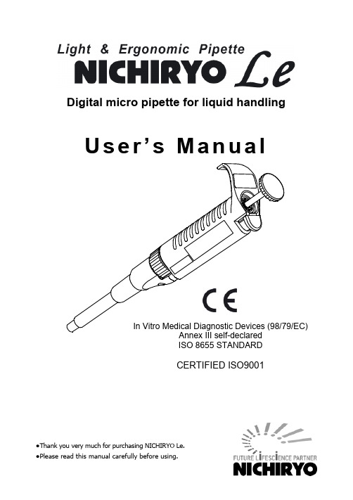
●Thank you very much for purchasing NICHIRYO Le. ●Please read this manual carefully before using.Digital micro pipette for liquid handling U s e r ’s M a n u al ISO 8655 STANDARDCERTIFIED ISO9001●Thank you for purchasing the NICHIRYO Le.● Before proceeding to work with the NICHIRYO Le, please carefully read this manual for proper use of it.I. IntroductionThis operator’s manual explains the operation of the Nichiryo Digital MicroPipette ‘NICHIRYO Le’. Please read carefully to ensure safe and correctoperation of the instrument. Please pay special attention to passages markedin bold lettering. Be sure to read cautions that need strict observance andunderlined sections before using the instrument.II. Features● As volume amount setting is done digitally, easy volume setting is possible with asimple press of the push button.● Through adoption of an easy to grasp design and a lightweight construction,(in comparison with our Nichipet EX model) we have realized a product design that allows long hours of use without operator fatigue.● The structure of the unit has been designed to reduce the effects of handtemperature on performance accuracy.● Our lineup of 5 different models allows a wide range of sampling, between1.0ul – 1000ul.III. Standard Accessories● Tips: x 3● Grease: x 1● User’s ManualWhen unpacking package, check to make sure that the above-mentioned items are included. IV. Safety Precautions●before using the instrument.●for using the Nichiryo Le properly but for preventing the user from accidents and physical damage.●After reading this manual, please keep it in a convenient place for easy referral atany time.Please read the following prior to use for your safety and correct usage of the instrument.Be sure to observe the following instructions for usingthe NICHIRYO Le properly and safely1. Do not use this instrument for any purpose except pipetting liquid.2. Do not modify this instrument as modification may cause an accident.3. Do not use this instrument for pipetting any liquid to be injected into thehuman body.4. Do not eject the tip towards anybody.5. Do not discharge any sample liquid while pointing the instrument at anybody.Some liquids are dangerous and may cause bodily harm.6. Do not eject the tip while liquid is still inside.7. Handle the tip with care, as the point is sharp and dangerous.8. Firmly attach the tip to the nozzle. If not attached securely it may fall offcausing the sample liquid to scatter.9. When handling liquid harmful to the human body, be careful not to directlytouch the tip during or after use.10. If the instrument is soiled with liquid harmful to the human body, immediatelytake proper measures to clean it safely before proceeding with work.11. Do not use this instrument for stirring liquid or for any other such action.Additionally, do not use the instrument in any manner that will cause the tip to loosen, fall off, or the instrument itself to be soiled with scattered liquid.12. Do not use this instrument for any purpose except pipetting liquid.Users are required to strictly observe the following points in order for the instrument to retain its precision and original performance for a long time.1. Do not expose this instrument directly to the sun when working with it, or for 2hours before starting work, otherwise the instrument may fail in precisepipetting. Avoid working with this instrument in a humid and hot place.2. Just before starting work with this instrument, avoid touching the tip andnozzle cylinder as far as circumstances permit. If the nozzle cylinder is warmed by your hand, it is hard to maintain accuracy.3. For pipetting, follow the forward method (explained in this manual). If it isperformed in a different way, it may result in inaccurate pipetting.4. Operate the push button slowly. If quickly released, sample liquid will besucked into the main body, which may result in not only inaccurate pipetting but also deterioration of the instrument.5. Do not hold the instrument horizontally or upside down when there is liquidinside the tip, otherwise the liquid will get inside the main body, which may cause deterioration of the instrument.6. If liquid is sucked inside the main body (inside the nozzle), clean as quickly aspossible. Liquid inside the nozzle is a main cause of precision/reproducibility loss and may lead to breakdown of the instrument.7. When turning the push button, do not exceed the specified sample volumelimit, as this may damage the instrument or cause deterioration.8. Do not perform pipetting with less liquid than the set volume. If the quantity isless than the set volume, this may cause the liquid to scatter into the mainbody, which may result in deterioration of the instrument.9. The pipette can be used between +4°C and +40°C, but the specifications mayvary.10. Depending on the frequency of use, the pipette should be cleaned in a soapsolution and maintained the airtight chamber according to this manual.Contents● Operating procedure (5)● Disassembling/Reassembling the airtight chamber (9)● Specifications (10)● Troubleshooting (11)● Parts list (12)V. Operation1. Volume settingFor each volume, the graduation consists of three numerical values that are read from top to bottom.Turn the push button to the left or right, aligning it with the numerical value of the setting volume.✱Graduation units of each model are as shown in the chart below.Observe the following cautions when setting volume.1) When setting to an increased volume → First exceed the desired setting graduationby about 1/3 revolution, then adjust the indication to the desired graduation.2) When setting to a decreased volume → Slowly turn to the precise point,being carefulnot to go past the desired graduation setting.●Do not exceed the stipulated volume range or change the volume capacity. This could damage the instrument or impair quality.(Never turn the push button more than 1/3 revolution past the maximum stipulated volume).2. Aspirating liquid (Forward method)1) Attach a new tip to the nozzle end. (We recommend that you attach it from rack)Note: It would be recommended that tips are directly picked up from rack.And do not twist pipette when fixing tip.2) Press down push button to first stop position “b”. (Fig. A)* Don’t aspirate the liquid with the push button pressed at the second stop “c”.3) Hold the pipette vertically and immerse the tip 2mm to 3mm below the surface ofthe liquid. (Fig. B-①)4) Release the push button slowly and smoothly to aspirate the set volume of theliquid. (Fig. B-②)5) Wait 1 to 2 seconds, then withdraw the pipette vertically and carefully from thesurface of the liquid. (Fig. B-②)6) Wipe any droplets away from the outside of the tip using a medical wipe and avoidtouching the tip’s orifice.Note: Do not aspirate when push button position is at “c”.Note: The push button has to be pushed and released slowly. Otherwise it may cause wrong accuracy.3. Dispensing liquid1) Gently place the end of tip against inside wall of recipient vessel just above liquidsurface 10 degrees to 45 degrees in angle.2) Press down the push button slowly and smoothly to the first stop “b”. Wait for afew seconds then press down the push button to the second stop to expel the last drop of the liquid from the tip. (Fig. D-④,⑤)3) Release the push button slowly.4) Press the ejector button to remove the tip and dispose of it. (Fig. D-⑥)When using any toxic or harmful liquid to human, do not touch any used tips.(Reference)1) Pre-rinsingWhen attaching a new tip, before sampling, repeat suction and discharge of liquid to the first stop position 2 to 3 times.Pre-rinsing will result in a high degree of accuracy. In addition, especially when strict accuracy is sought, we recommend this method when sampling various types of liquid.2) Sampling high density liquids and viscous solutionsWhen aspirating, once the liquid has entered the tip, wait 2 to 3 seconds before removing the tip from the liquid. When dispensing, wait 2 to 3 seconds at the first stop position before pushing to the second stop position.VI. Disassembly and assembly of airtight sectionFor airtight section maintenance, or when a problem such as that clearly stated in the “Trouble Shooting” section of this manual occurs, carry out disassembly,inspection and cleaning following the instructions below.1. Disassembly1) Remove the ejector pipe.With the ejector button depressed, slide the ejector pipe to the right (clockwise direction) and remove from the ejector shaft. Next, pull out the ejector pipe. (Refer to Fig.D).2) Remove the bottom nut.While holding down the nozzle cylinder, turn the bottom nutcounter clockwise and remove from the body.At this time the spring inside the nozzle cylinder may causethe internal parts to pop out. Please use care and removeslowly.3) Remove each part.Remove the parts in the nozzle cylinder: First spring, plunger, first spring holder, second spring and O-ring. (The plunger and first spring holder area c o m p le te se t o n t h e1000u l mo de l).O n c e r e mov e d,c a r r y o u t pa r treplacement, inspection and cleaning of the airtight section.●During disassembling take care not to lose any of the parts.2. Assembly✱Basically assembly is done in the reverse order of disassembly. (Referto Fig.E ).1) Set the O-ring on the O-ring holder.2) With the plunger tip facing upward, attach each part in the order of first spring →first spring holder → stroke pipe → second spring → O-ring retainer → O-ring.Next, insert in the nozzle cylinder.3) Install the ejector pipe. Install in the reverse order of disassembly.●After assembly, before using the unit, test-operate it a few times toconfirm that there are no problemsVII. SpecificationsNichiryo Le (model No. NLE) is a high quality pipette. The technical figures given in the Table-1 “NLE Maximum Permissible Errors” were obtained using genuine Nichiryo BMT tips. Nichiryo declares that pipettes comply with the requirements of the ISO 8655 Standard, by type testing. The adjustment is carried out under strictly defined and monitored conditions (ISO 8655-6):● The basis of adjustment, EX● Reference temperature, 20°C● Relative humidity, 50%● Barometric pressure, 101KPa● Use of distilled water grade 3 (ISO 3696)● Ten measurements for each test volume at three points, nominal volume,50% of nominal volume and the minimum or 10% of nominal volume.Table-1 NLE Maximum Permissible ErrorsCodeVolumerange (uL)Measuredvolume(uL)Accuracy(systematicerror)(%)Precision(randomerror)(%)NLE-10 1~10 1 ±6.0*≦5.0*5 ±2.0≦1.6 10 ±1.2 ≦0.8NLE-20 2~20 2 ±5.0*≦3.0*10 ±2.0 ≦1.0 20 ±1.0 ≦0.5NLE-100 10~100 10 ±2.0 ≦1.0 50 ±1.2 ≦0.6 100 ±0.8 ≦0.3NLE-200 20~200 20 ±1.2 ≦1.0 100 ±1.0 ≦0.6 200 ±0.8 ≦0.3NLE-1000 100~1000100 ±1.2 ≦0.8 500 ±1.0 ≦0.6 1000 ±0.7 ≦0.3✱Accuracy and reproducibility of 1uL on the NLE-10 model and 2uL on the NLE-20 model will be greatly influenced by the operator’s sampling skill.✱The data given in the table conform to the ISO 8655-2 standard.VIII. Trouble ShootingProblem Probablecause SolutionLiquid is not suctioned Inside of nozzle cylinder point isclogged (foreign matter buildup)Clean or replace the nozzlecylinder part.The nozzle cylinder is loose Retighten the bottom nut. The O-ring is worn Replace the O-ring.Suctioned liquid leaks from the tip The O-ring is worn Replace the O-ring. Airtight section lubricant (grease)has been used up.Grease the airtight section.Nozzle cylinder point is worn.(Visual inspection shows leveldifference).Replace the nozzle cylinder.Plunger surface is scratched ordamaged.Replace the plunger.The tip being used does not fit thenozzle.Change the tip used.Push button operation is poor Plunger and O-ring lubricant(grease) has been used up.Grease the plunger and O-ring.Liquid has been drawn into the unit(inside of nozzle cylinder)Disassemble the lower part andclean.Plunger surface is dirty or foreignmatter has adhered to it.Disassemble the lower part andclean or replace the plunger.✱If you experience any problems other than those noted above, or if there is stilla problem even after carrying out the recommended solutions, please stop usingthe instrument immediately and request service. At that time please be sure to make sure that the instrument is not contaminated with any substances such as microbes or chemicals that are harmful to the body.■Replacement parts list (Service parts list)Description NLE-10NLE-20NLE-100NLE-200NLE-1000①Nozzle cylinder NPE-024A NPE-024B NPE-024C NPE-024D NPE-024E②Bottom nut NPE-030 *Same for all volume sizes.③Ejector pipe NPE-025A NPE-025B NPE-025B NPE-025B NPE-025C④Plunger NPE-017A NPE-017B NPE-017C NPE-017D NPE-017E⑤First spring NPE-017A NPE-017B NPE-017C NPE-017C NPE-017D⑥First spring holder NPE-020A NPE-020A NPE-020A NPE-020A NPE-020B⑦Stroke ring NPE-018A NPE-018A NPE-018A NPE-018A NPE-018B⑧Second spring NPE-023A NPE-023A NPE-023A NPE-023A NPE-023B⑨O-ring retainer NPE-021A NPE-021B NPE-021C NPE-021D NPE-021E⑩O-ring NPE-022A NPE-022B NPE-022C NPE-022D NPE-022E ⑪Grease N3-0711A N3-0711A N3-0711A N3-0711A N3-0711A✱As the above replacement parts are specifically designed for each volume size, please indicate the volume size of your instrument when placing your order.■Nichiryo Genuine Tips●Tips (Autoclavable)Code Volume range(uL) Color Applicable modelTip length(approx. size)Numberof tipsBMT2-SS 0.5~10 clear NLE-10 45.7mm1000tips BMT2-SG 2~200 clear NLE-20/100/200 53mm 1000tipsBMT2-LG 100~1000 clear NLE-1000 81.9mm1000tips ●Racked tips (Autoclavable)Code Volumerange(uL)Color Applicable model Number of tipsBMT2-SSR 0.5~10 clear NLE-10 960 tips(96 tips x 10 cases)BMT2-SGR 2~200 clear NLE-20/100/200 960 tips(96 tips x 10 cases)960 tipsInspection and Calibration StatementThe enclosed pipette was tested and calibrated under closely controlled environmental conditions to ensure that it meets published calibration specifications. The precision and accuracy results obtained for this pipette are provided on the enclosed calibration certificate.Because temperature and humidity conditions affect the calibration results of liquid measurement devices, your pipette should be calibrated under conditions of use. The calibration results obtained in your laboratory may vary from our results due to differences in environmental testing conditions.For repair, service or information you may contact your local distributor.Manufacturer:Tokyo office1-10-1 Kandanishiki-cho, Chiyoda-ku, Tokyo 101-0054, JapanTEL: +81-3-6273-7652(English) FAX: +81-3-6273-7944URL: http://www.nichiryo.co.jp/E-mail:*******************.jp。
TOM811
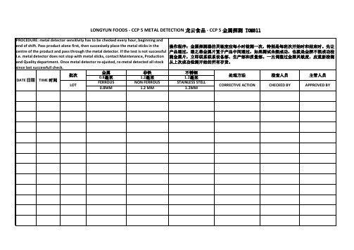
LONGYUN FOODS - CCP 5 METAL DETECTION 龙云食品 - CCP 5 金属探测 TOM811
PROCEDURE: metal detector sensitivity has to be checked every hour, beginning and end of shift. Pass product alone first, then succesively place the metal sticks in the centre of the product and pass through the metal detector. If the test is not successful i.e. metal detector does not stop with metal sticks, contact Maintenance, Production and Quality department. Once metal detector re-ajusted, re-metal detected all stock since last successfull check. 金属 非铁 批次 0.8毫米 1.2毫米 DATE 日期 TIME 时间 FERROUS NON FERROUS LOT 0.8MM 1.2 MM 操作程序:金属探测器的灵敏度应每小时检测一次,特别是每班次开始时和结束时。先 让产品通过,继之将金属片置于产品中间通过,如果测试未能成功,也就是金探不能成 功检测金属片,立即联系联系设备部、生产部和质量部。一旦调整过金探灵敏度,应重 新检测从上次成功检测开始的所有存货。 不锈钢 1.2毫米 STAINLESS STELL 1.2MM 处理方法 CORRECTIVE ACTION 检查人员 CHECKED BY 主管人员 APPROVED BY
ch05_第五章_ 计算机产品说明书
New Words and Expressions
• • • • • • • • • • • • • • •
motherboard / m b :d/ n. :d/ 主板 R&D 研究与开发 outstanding /aut st ndi / a. 突出的, 突出的,显著的 dynamic /dai n mik/ a. mik/ 动态的 establish /i st bli / vt. 建立, 建立,设立 enterprise / ent praiz/ n. praiz/ 企业 enthusiast /in ju:zi st/ n. st/ 热心家, 热心家,发烧友 purchaser / p :t s / n. 买方, 买方,购买者 socket / s kit/ n. kit/ 插座 channel / t n l/ n. 通道 legacy / leg si/ n. si/ 遗产 bandwidth / b ndwi / n. 带宽 Ethernet n. 以太网 expansion /ik sp n n/ n. 扩充 specification /spesifi kei n/ n. 规范
New Words and Expressions
• • • • • • • • • • • • • • • area / e ri / n. 区域 maximum / m ksim m/ n. 最大值 instruction /in str k n/ n. 说明书 aerosol / e r s l/ a. 喷雾的 damp /d mp/ a. mp/ 潮湿的 attachment / t t m nt/ n. 配件 nt/ manufacturer /m nju f kt / n. 生产商 hazard / h z d/ n. 危险 bathtub / ba: t b/ n. 浴缸 washbowl / w : b ul/ n. ul/ 脸盆 appliance / plai ns/ n. ns/ 应用, 应用,装置 consult /k n s lt/ vt. lt/ 请教 equip /i kwip/ vt. kwip/ 装配 obsolete / bs li:t/ n. li:t/ 丢弃 surge /s :d / vt. 松落
- 1、下载文档前请自行甄别文档内容的完整性,平台不提供额外的编辑、内容补充、找答案等附加服务。
- 2、"仅部分预览"的文档,不可在线预览部分如存在完整性等问题,可反馈申请退款(可完整预览的文档不适用该条件!)。
- 3、如文档侵犯您的权益,请联系客服反馈,我们会尽快为您处理(人工客服工作时间:9:00-18:30)。
ELASTICITY AND ITS APPLICATION
4
Price Elasticity of Demand
Price elasticity of demand Percentage change in Qd
=
Percentage change in P
P P rises P2 by 10% P1 D Q2 Q falls by 15%
1
A scenario…
You design websites for local businesses. You charge $200 per website, and currently sell 12 websites per month. Your costs are rising (including the opportunity cost of your time), so you consider raising the price to $250. The law of demand says that you won’t sell as many websites if you raise your price. How many fewer websites? How much will your revenue fall, or might it increase?
In this chapter, look for the answers to these questions:
What is elasticity? What kinds of issues can elasticity help us understand? What is the price elasticity of demand? How is it related to the demand curve? How is it related to revenue & expenditure? What is the price elasticity of supply? How is it related to the supply curve? What are the income and cross-price elasticities of demand?
12 – 8 x 100% = 40.0% 10
The price elasticity of demand equals
40/22.2 = 1.8
ELASTICITY AND ITS APPLICATION
10
ACTIVE LEARNING
1
Calculate an elasticity
Use the following information to calculate the price elasticity of demand for hotel rooms: if P = $70, Qd = 5000 if P = $90, Qd = 3000
CHAPTER
5
Elasticity and its Application
Economics
PRINCIPLES OF
N. Gregory Mankiw
Premium PowerPoint Slides by Ron Cronovich
© 2009 South-Western, a part of Cengage Learning, all rights reserved
8
ELASTICITY AND ITS APPLICATION
Calculating Percentage Changes
So, we instead use the midpoint method:
end value – start value x 100% midpoint
The midpoint is the number halfway between the start & end values, the average of those values. It doesn’t matter which value you use as the “start” and which as the “end” – you get the same answer either way!
2
Elasticity
Basic idea: Elasticity measures how much one variable responds to changes in another variable. One type of elasticity measures how much demand for your websites will fall if you raise your price. Definition: Elasticity is a numerical measure of the responsiveness of Qd or Qs to one of its determinants.
ELASTICITY AND ITS APPLICATION
13
EXAMPLE 1:
Breakfast cereal vs. Sunscreen
The prices of both of these goods rise by 20%. For which good does Qd drop the most? Why? Breakfast cereal has close substitutes (e.g., pancakes, Eggo waffles, leftover pizza), so buyers can easily switch if the price rises. Sunscreen has no close substitutes, so consumers would probably not buy much less if its price rises. Lesson: Price elasticity is higher when close substitutes are available.
Suppose the prices of both goods rise by 20%. The good for which Qd falls the most (in percent) has the highest price elasticity of demand. Which good is it? Why? What lesson does the example teach us about the determinants of the price elasticity of demand?
12
What determines price elasticity?
To learn the determinants of price elasticity, we look at a series of examples. Each compares two common goods. In each example:
11
ACTIVE LEARNING
1
Answers
Use midpoint method to calculate % change in Qd (5000 – 3000)/4000 = 50% % change in P ($90 – $70)/$80 = 25% The price elasticity of demand equals 50% = 2.0 25%
ELASTICITY AND ITS APPLICATION
14
EXAMPLE 2:
“Blue Jeans” vs. “Clothing”
The prices of both goods rise by 20%. For which good does Qd drop the most? Why? For a narrowly defined good such as blue jeans, there are many substitutes (khakis, shorts, Speedos). There are fewer substitutes available for broadly defined goods. (There aren’t too many substitutes for clothing, other than living in a nudist colony.) Lesson: Price elasticity is higher for narrowly defined goods than broadly defined ones.
5
Example:
Price elasticity of demand equals 15% = 1.5 10%
Q1
Q
ELASTICITY AND ITS APPLICATION
Price Elasticity of Demand
Price elasticity of demand Percentage change in Qd
ELASTICITY AND ITS APPLICATION
3
Price Elasticity of Demand
Price elasticity of demand Percentage change in Qd
=
Percentage change in P
Price elasticity of demand measures how much Qd responds to a change in P. Loosely speaking, it measures the pricesensitivity of buyers’ demand.
