LDM-21457MI, 规格书,Datasheet 资料
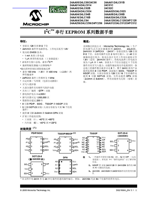
24lc256系列中文
1.8-5.5V 400 kHz (2) 2.5-5.5V 400 kHz 1.8-5.5V 400 kHz(2) 2.5-5.5V 400 kHz 4.5V-5.5V 400 kHz
8 字节
16 字节 16 字节
整个阵列
整个阵列 无
无
A0, A1, A2 A0, A1, A2
I I, E
I I C, I, E
装。
封装类型 (1)
PDIP/SOIC
TSSOP/MSOP(2)
A0 1 A1 2 A2 3 VSS 4
8 VCC
A0 1
7 WP(3) A1 2
6 SCL
A2 3
5 SDA VSS 4
8 VCC
A0 A1
7 WP(3) NC NC
6 SCL NC
5
SDA
A2 VSS
TSSOP
1
14
2
13
3
12
4
11
1.8-5.5V 2.5-5.5V 1.8-5.5V
400 kHz (2)
400 kHz 1 MHz(3)
64 字节
整个阵列
A0, A1, A2(4)
I
P, SN, SM, ST, MS, MF,
I, E ST14
I
256 千位器件
24AA256
1.8-5.5V 400 kHz (2)
24LC256 24FC256
2005 Microchip Technology Inc.
DS21930A_CN 第 3 页
24AAXX/24LCXX/24FCXX
2.0 电气特性
绝对最大额定值 (†)
VCC.............................................................................................................................................................................6.5V 相对于 Vss 的所有输入和输出 ............................................................................................................ -0.6V 到 VCC +1.0V 存储温度 ................................................................................................................................................. -65°C 到 +150°C 环境温度 (使用电源时)........................................................................................................................ -40°C 到 +125°C 所有引脚静电保护 ....................................................................................................................................................................≥ 4 kV
SLMC 数显流量开关集成型说明书 - PF2M7##系列

Instruction ManualPF2M7## seriesThe intended use of the digital flow switch is to monitor and display flow information.These safety instructions are intended to prevent hazardous situations and/or equipment damage. These instructions indicate the level of potential hazard with the labels of “Caution,” “Warning” or “Danger.”They are all important notes for safety and must be followed in addition to International Standards (ISO/IEC) *1), and other safety regulations. *1)ISO 4414: Pneumatic fluid power - General rules relating to systems. ISO 4413: Hydraulic fluid power - General rules relating to systems.IEC 60204-1: Safety of machinery - Electrical equipment of machines. (Part 1: General requirements)ISO 10218-1: Manipulating industrial robots -Safety. etc.∙ Refer to product catalogue, Operation Manual and Handling Precautions for SMC Products for additional information. ∙ Keep this manual in a safe place for future reference.∙ This product is class A equipment intended for use in an industrial environment. There may be potential difficulties in ensuring electromagnetic compatibility in other environments due to conducted or radiated disturbances.CautionCaution indicates a hazard with a low level of risk which, ifnot avoided, could result in minor or moderate injury.WarningWarning indicates a hazard with a medium level of riskwhich, if not avoided, could result in death or serious injury.DangerDanger indicates a hazard with a high level of risk which, ifnot avoided, will result in death or serious injury.Warning∙ Always ensure compliance with relevant safety laws and standards.∙ All work must be carried out in a safe manner by a qualified person in compliance with applicable national regulations.∙ Do not disassemble, modify (including changing the printed circuit board) or repair. An injury or failure can result.∙ Do not operate the product outside of the specifications. Fire, malfunction or damage to the product can result.∙ Do not operate in an atmosphere containing flammable, explosive or corrosive gas.Fire or an explosion can result.∙ Do not use the product for flammable fluids. Fire, explosion, damage or corrosion can result. ∙ If using the product in an interlocking circuit:Provide a double interlocking system, for example a mechanical system.∙ Check the product for correct operation.Otherwise malfunction can result, causing an accident.∙ Do not use the product in a place where static electricity is a problem.Product failure or system malfunction may result.Otherwise electric shock, malfunction or product damage can result. ∙ Refer to the operation manual on the SMC website (URL: https:// ) for more safety instructions.2 SpecificationsWarningSpecial products (-X) might have specifications different from those shown in this section. Contact SMC for specific drawings.3.1 PF2M7## (with flow adjustment valve)ItemDescriptionSocket Socket for electrical connections.Piping port Connected to the fluid inlet IN side and to the fluid outlet OUT side.Flow adjustment valve Orifice mechanism to adjust the flow. Lock ring Used to lock the flow adjustment valve.Mounting hole Used to mount the product on a DIN rail or directly to a panel.BodyThe body of the product.Lead wire and connector Lead wire to supply power and output signals.3.2 DisplayItem DescriptionUP buttonSelects the mode or increases the ON/OFF set value. Press this button to change to the peak display mode.DOWN button Selects the mode or decreases the ON/OFF set value.Press this button to change to the bottom displaymode.Main displayDisplays the flow value, setting mode, and error indication.Four display modes can be selected: display always in red or green, or display changing from green to red, or red to green, according to the output status (OUT1). SET button Press this button to change to another mode and to set a value.Output display (Operation LED) Displays the output status of OUT1 and OUT2. OUT1: LED is ON (Orange) when the output is ON. OUT2: LED is ON (Orange) when the output is ON. When the accumulated pulse output mode is selected, the output display is OFF.Units display Arbitrary units are ON based on the flow display setting (instantaneous or accumulated flow)IO-Link status indicator light LED is ON when OUT1 is used in IO-Link mode. (LED is OFF in SIO mode)ORIGINAL INSTRUCTIONSModel 701 702 705 710 725 750 711 721 F l u i dApplicable fluidDry air, N 2, Ar, CO 2(ISO8573-1 1.1.2 to 1.6.2)Fluid temperature range 0 to 50 o CF l o w r a t e Detection method Thermal(main flow) Thermal (branch flow) R a t e d f l o w r a n g e [L /m i n ] Dry air,N 2,Ar 0.01 to 1 0.02 to 2 0.05 to 5 0.1 to 10 0.3 to 25 0.5 to 50 1 to 100 2 to200CO 20.01 to 0.5 0.02 to 1 0.05 to 2.5 0.1 to 5 0.3 to 12.5 0.5 to 25 1 to 50 2 to100S e t f l o w r a n g e Instantaneous flow [L/min]-0.05 to 1.05 -0.1 to 2.1 -0.25 to 5.25 -0.5 to 10.5 -1.3 to 26.3 -2.5 to 52.5 -5 to 105 -10 to 210Accumulated flow [L] 0.00 to 9999999.99 0.0 to 99999999.9 0 to 999999999 M i n . s e t t i n g u n i t Instantaneous flow [L/min] 0.001 0.01 0.1 1Accumulatedflow [L]0.01 0.1 1 Accumulatedvolume [L/pulse]0.01 0.1 1 Accumulated value hold Select from 2 and 5 minutesP r e s s u r eOperating pressure range-0.1 to 0.75 MPa Rated pressurerange-0.07 to 0.75 MPaProof pressure 1.0 MPa Pressure loss Refer to the pressure loss graph. Pressure characteristics ±5%F.S. ±1 digit (0.35 MPa standard)E l e c t r i c a l P o w e r s u p p l y v o l t a g e Switch output device 12 to 24 VDC ±10% IO-Link device18 to 30 VDC ±10% Currentconsumption 35 mA or less ProtectionPolarity protection A c c u r a c yDisplay accuracy ±3% F.S. ±1 digitAnalogue output accuracy ±3% F.S.Repeatability ±1%F.S. ±1 digit(±2% F.S. ±1 digit when digital filter is set to 0.05 s) Temperature characteristics ±3%F.S. ±1 digit (15 to 35 oC: 25 oC standard) ±5%F.S. ±1 digit (0 to 50 o C: 25 o C standard) S w i t c h o u t p u tOutput type NPN or PNP open collectorOutput mode Select from hysteresis mode, window comparator mode, accumulated output mode, accumulated pulse output mode, error outputand switch output OFFSwitch operation Select from normal output and reversed outputMaximum load current80 mA Maximum applied voltage 28 VDC (NPN only)I n t e r n a l v o l t a g e d r o pStandard valueNPN: 1 V or less (Load current 80 mA) PNP: 1.5 V or less (Load current 80 mA) IO-Link compatible product 1.5 V or less (Load current 80 mA) Response time 50 ms or lessDelay time 0 to 0.10 s (0.01 s increment), 0.1 to 1.0 s (0.1 s increment), 1 to 10 s (1 s increment)Select from 20 s, 30 s, 40 s, 50 s, 60 sHysteresis VariableProtectionShort circuit protectionModel 701 702 705 710 725 750 711 721 A n a l o g u e o u t p u tOutput type Voltage output: 1 to 5 V (or 0 to 10 V),Current output 4 to 20 mAI m p e d a n c e Voltage outputOutput impedance approx.1 kΩ CurrentoutputMax. load impedance Power supply voltage 24 V: 600 Ω Power supply voltage 12 V: 300 Ω Response time 50 ms ±40% D i s p l a yReference conditionSelect from normal condition (NOR) andstandard condition (STD) Display mode Select from instantaneous flow andaccumulated flow U n i t InstantaneousflowL/min, cfm Accumulated flowL, ft 3 D i s p l a y a b l e r a n g e Instantaneous flow [L/min]-0.05 to 1.05 -0.1 to 2.1 -0.25 to 5.25 -0.5 to 10.5 -1.3 to 26.3 -2.5 to 52.5 -5 to 105 -10 to 210 Zero cut-off range 0 to ±10%F.S. (selected for every 1%F.S. of max. rated flow rate) Accumulated flow [L] 0.00 to 9999999.99 0.0 to99999999.9 0 to 999999999Display Display type: LCD, Display colour: Red, green,Display digit: 7-segment, 4 digits Operation LED LED is ON when switch output is ON,OUT1/OUT2: Orange Digital filterSelect from 0.05 s, 0.1 s, 0.5 s, 1 s, 2 s and 5 s E n v i r o n m e n t a l r e s i s t a n c eEnclosure IP40 Withstand voltage 1000 VAC, 1 min. between terminals andhousing Insulation resistance 50 MΩ or longer (with 500 VDC) between terminals and housing Operatingtemperature rangeOperation: 0 to 50 o C, Storage: -10 to 60 o C(no freezing or condensation)Operating humidity range Operation, Storage: 35 to 85%R.H. (no freezing or condensation) P i p i n gP i p i n g s p e c i f i c a t i o n One-touch fitting C4 (ϕ4) / C6 (ϕ6)C6 (ϕ6) / N7 (ϕ1/4”) C8 (ϕ8) / N7 (ϕ1/4”)Screw fitting (Rc/NPT/G) 01 (Rc1/8) N1 (NPT1/8) F1 (G1/8)02 (Rc1/4) N2 (NPT1/4) F2 (G1/4)Port direction Straight, RearMaterial fluid contact parts PPS, PBT, FKM, SUS304, brass (electrolessnickel plating), Si, Au, GE4FW e i g h tB o d y One-touch fitting Straight: 40 g Rear: 55 g 48 g 63 g Screw fittingStraight: 60 g Rear: 75 g 72 g 87 gFlow adjustment valve -+34 g Lead wire +35 g Bracket +20 g Panel mount adapter +15 g DIN rail mounting bracket +65 gThe product code is displayed for approximately 3 seconds afterpower is supplied.Then measurement mode will be displayed and the switchoperation will start.4.1 InstallationWarning∙Do not install the product unless the safety instructions have been readand understood.∙Use the product within the specified operating pressure andtemperature range.∙Proof pressure could vary according to the fluid temperature. Checkthe characteristics data for operating pressure and proof pressure.4.2 EnvironmentWarning∙Do not use in an environment where corrosive gases, chemicals, saltwater or steam are present.∙Do not use in an explosive atmosphere.∙Do not expose to direct sunlight. Use a suitable protective cover.∙Do not install in a location subject to vibration or impact in excess ofthe product’s specifications.∙Do not mount in a location exposed to radiant heat that would result intemperatures in excess of the product’s specifications.∙Refer to the flow direction of the fluid indicated on the product forinstallation and piping.∙Do not mount the body with the bottom facing upwards.Retention of air can cause inability to measure accurately.∙Do not insert metal wires or other foreign matter into the piping port.This can damage the sensor causing failure or malfunction.∙Never mount a product in a location that will be used as a foothold.The product may be damaged if excessive force is applied by steppingor climbing onto it.∙If there is a risk of foreign matter entering the fluid, install and pipe afilter or mist separator at the inlet to avoid failure and malfunction.Otherwise damage or malfunction can result.4.3 Panel mounting∙Insert panel mount adapter B (supplied as an accessory) into sectionA of the panel mount adapter.Push panel mount adapter B from behind until the display is fixed ontothe panel.The bracket pin engages the notched part of panel adapter section Cto fix the display.∙The switch can be mounted on a panel with a thickness of 1 to 3.2 mm.4.4 Bracket mounting∙Mount the bracket using the mounting screws supplied.∙The required tightening torque is 0.42 ±0.04 N•m.∙Install the product (with bracket) using the M3 screws (4 pcs.).∙Bracket thickness is approximately 1.2 mm.4.5 DIN rail mounting (using ZS-33-R#)∙Mount the DIN rail mounting parts using the mounting screws and jointscrews supplied.∙The required tightening torque of the DIN rail mounting screws and∙Refer to the operation manual on the SMC website(URL: https://) for all mounting dimensions.4.6 PipingCaution∙Before connecting piping make sure to clean up chips, cutting oil, dust etc.∙Ensure there is no leakage after piping.∙Any dust left in the piping should be flushed out by air blow beforeconnecting piping to the product.Otherwise damage or malfunction can result.∙For piping of the product, hold the piping with a wrench on the metalpart of the product.Holding other parts of the product with a wrench may damage the product.4.7 WiringCaution∙Do not perform wiring while the power is on.∙Confirm proper insulation of wiring.∙Do not route wires and cables together with power or high voltage cables.Otherwise the product can malfunction due to interference of noise andsurge voltage from power and high voltage cables to the signal line.∙Keep wiring as short as possible to prevent interference fromelectromagnetic noise and surge voltage. Do not use a cable longerthan 30 m. When using it as an IO-Link device, do not use a cablelonger than 20 m.∙Ensure that the FG terminal is connected to ground when using acommercially available switch-mode power supply.∙When the analogue output is used, install a noise filter (line noise filter,ferrite element, etc.) between the switch-mode power supply and thisproduct.Connecting / Disconnecting∙When mounting the connector, insert it straight into the socket, holdingthe lever and connector body, and push the connector until the leverhooks into the housing, and locks.∙When removing the connector, press down the lever to release thehook from the housing and pull the connector straight out.Connector pin numbers (on the lead wire)•Lead wire and connector (ZS-33-D)No. Signal name Lead wire colour1 DC(+) Brown2 OUT2 White3 OUT1 Black4 DC(-) Blue•M12 conversion lead wire (ZS-33-DM)Used as switch output deviceNo. Signal name Lead wire colour1 DC(+) Brown2 N.C./OUT2 White3 DC(-) Blue4 OUT1 BlackUsed as IO-Link deviceNo. Signal name Lead wire colour1 L+Brown2 N.C./OUT2 White3 L-Blue4 C/Q BlackPower is supplied*: The outputs will continue to operate during setting.*: Simple setting mode and function selection mode settings arereflected each other.6 Flow Setting6.1 Switch operationWhen the flow exceeds the set value, the switch will be turned ON.When the flow falls below the set value by the amount of hysteresis ormore, the switch will be turned OFF.The default setting is to turn on the flow switch when the flow reaches thecentre of the upper limit of the rated flow range.If the operation shown below is acceptable, keep this setting.*: For hysteresis refer to [F 1] Setting of OUT1 and [F 2] Setting of OUT2.Without flow adjustmentvalve (using ZS-33-M)With flow adjustment valve(using ZS-33-MS)Press the SETbutton for 5seconds or longerPress the SETbutton between2 to 5 secondsPress the SETbutton onceFlow Setting andHysteresis(Simple settingmode)Function Setting(Functionselection mode)Other Settings∙Snap shot∙Key-lock∙Zero clear[Simple setting mode (Hysteresis mode)]In the Simple setting mode, the set value and hysteresis can be changed. (1) Press the SET button once in measurement mode.[P_1] or [n_1] and the [current set value] are displayed alternately.(2) Change the set value using the UP or DOWN button and press theSET button to set the value. Then, the setting moves to hysteresis setting (The snap shot function can be used). ∙ Press the UP button continuously to keep increasing the set value.∙ Press the DOWN button continuously to keep decreasing the set value.(3) [H_1] and the current set value are displayed in turn.(4) Change the hysteresis by pressing the UP or DOWN button and press the SET button. Setting is completed and the product returns to measurement mode (The snap shot function can be used).* For models with switch outputs for both OUT1 and OUT2, [P_2] or [n_2] will be displayed. These are set simultaneously.* After enabling the setting by pressing the SET button, it is possible to return to measurement mode by pressing the SET button for 2 seconds or longer.* When hysteresis mode is not used, "Input set value” is displayed. * The set value and hysteresis settings limit each other.* For more detailed setting, set each function in function selection mode.8.1 Function selection modeIn measurement mode, press the SET button for 2 to 5 seconds to display [F 0] on the display.Select to display the function to be change [F ].Press the SET button for 2 seconds or longer in function selection mode to return to measurement mode. *: Some products do not have all the functions. If a function is not available or selected due to configuration of other functions, [- - -] is displayed.8.2 Default settings*: Setting is only possible for models with the units selection function. *: Only available for models with switch outputs for both OUT1 and OUT2.*: This function is available for models with analogue output. Analogue free span function can be selected.*: This function is available in IO-Link compatible products. *: This function is available for models with external input.9 Other Settings∙ Snap shot function∙ Peak/bottom value indication ∙ Reset∙ Key-lock function ∙Zero clear functionRefer to the operation manual on the SMC website(URL: https:// ) for setting these functions.10.1 General MaintenanceCaution∙ Not following proper maintenance procedures could cause the product to malfunction and lead to equipment damage.∙ If handled improperly, compressed air can be dangerous.∙ Maintenance of pneumatic systems should be performed only by qualified personnel.∙ Before performing maintenance, turn off the power supply and be sure to cut off the supply pressure. Confirm that the air is released to atmosphere.∙ After installation and maintenance, apply operating pressure and power to the equipment and perform appropriate functional and leakage tests to make sure the equipment is installed correctly.∙ If any electrical connections are disturbed during maintenance, ensure they are reconnected correctly and safety checks are carried out as required to ensure continued compliance with applicable national regulations.∙ Do not make any modification to the product.∙ Do not disassemble the product, unless required by installation or maintenance instructions.∙ How to reset the product after a power cut or when the power has been unexpectedly removedThe settings of the product are retained from before the power cut or de-energizing.The output condition also recovers to that before the power cut or de-energizing, but may change depending on the operating environment. Therefore, check the safety of the whole system before operating the product.11 How to OrderRefer to drawings/catalogue on the SMC website (URL: https:// ) for ‘How to Order’ information.12 Outline Dimensions (mm)Refer to the operation manual on the SMC website(URL: https:// ) for outline dimensions.ItemDefault setting[F 0] [FLU] [FLU] Select the flow rate[Air] Dry air, N 2[rEF] Setting the unitscriteria [Std] Standard condition [Unit] Measurement unitsetting [ L] L/min (L) [norP] Switch output PNP/NPN setting [PnP] PNP output [i_o] SW / external input setting[oUt] SW output [F 1] [oUt1][oUt1] Setting of OUT1[HYS] Hysteresis mode[1ot] OUT1 outputconfiguration setting [1_P] Normal output[P_1] Set value [ ] 50% of maximum rated flow PF2M701: 0.5 L/min, PF2M702: 1.0 L/minPF2M705: 2.5 L/min, PF2M710: 5 L/minPF2M725: 12.5 L/min, PF2M750: 25 L/minPF2M711: 50 L/min PF2M721: 100 L/min[H_1] Hysteresis [ ] 5% of maximum rated flow PF2M701: 0.05 L/min,PF2M702: 0.1 L/minPF2M705: 0.25 L/min,PF2M710: 0.5 L/min PF2M725: 1.3 L/min, PF2M750: 2.5 L/minPF2M711: 5 L/min PF2M721: 10 L/min[dt1] Delay time setting [0.00] 0.00 s [CoL] Display colour setting [1SoG] ON: Green OFF: Red[F 2][oUt2][oUt2] Setting of OUT2[HYS] Hysteresis mode[2ot] OUT2 outputconfiguration setting [2_P] Normal output[P_2] Set value [ ] 50% of maximum rated flow PF2M701: 0.5 L/min,PF2M702: 1.0 L/min PF2M705: 2.5 L/min,PF2M710: 5 L/min PF2M725: 12.5 L/min,PF2M750: 25 L/minPF2M711: 50 L/minPF2M721: 100 L/min [H_2] Hysteresis [ ] 5% of maximum rated flow PF2M701: 0.05 L/min,PF2M702: 0.1 L/min PF2M705: 0.25 L/min,PF2M710: 0.5 L/min PF2M725: 1.3 L/min,PF2M750: 2.5 L/minPF2M711: 5 L/minPF2M721: 10 L/min [dt2] Delay time setting [0.00] 0.00 s [CoL] Display colour setting[1SoG] ON: Green OFF: Red[F 3] [FiL] [FiL] Digital filter setting [1.0] 1.0 s [F 4] [PrS] [PrS] Auto-preset function setting [oFF] Manual Item Default setting[F10] [FLo] [FLo] Display mode [inS] Instantaneous flow [F11] [drE] [drE] Display resolutionsetting [1000] 1000-split [F13] [rEv] [rEv] Reverse display[oFF] Not reverse[F14] [CUt] [CUt] Zero cut-off setting[1.0] 1% of maximum rated flow PF2M701: 0.01 L/min, PF2M702: 0.02 L/min PF2M705: 0.05 L/min, PF2M710: 0.1 L/min PF2M725: 0.3 L/min, PF2M750: 0.5 L/min PF2M711: 1 L/min PF2M721: 2 L/min[F20] [inP] [inP] External input setting [rAC] Accumulated value reset[F22] [AoUt] [AoUt] Analogue output setting [1-5] 1 to 5 V Voltage output(when voltage is output) [---] Analogue output is notselectable(for current type output)[F30] [SAvE] [SAvE] Accumulated flowvalue hold setting[oFF] Not held [F80] [diSP] [diSP] Display OFF modesetting[ on] Normal display [F81][Pin] [Pin] Security code [oFF] Unused[F90] [ALL][ALL] Setting of allfunctions[oFF] Unused[F96] [S_in][S_in] External input signalcheck No setting due to input signal setting[F98][tESt] [tESt] Output checking[ n] Normal output [F99] [ini][ini] Reset to the defaultsettings[oFF] Not recover13.1 Error indicationIf the error cannot be reset after the above measures are taken, or errors other than above are displayed, please contact SMC.Refer to the operation manual on the SMC website (URL: https://) for more detailed information about troubleshooting. 14.1 Limited warranty and Disclaimer/Compliance RequirementsRefer to Handling Precautions for SMC Products.15 Product disposalThis product should not be disposed of as municipal waste. Check yourlocal regulations and guidelines to dispose this product correctly, in orderto reduce the impact on human health and the environment.16 ContactsRefer to or www.smc.eu for contacts.URL: https:// (Global) https://www.smc.eu (Europe)SMC Corporation, 4-14-1, Sotokanda, Chiyoda-ku, Tokyo 101-0021, JapanSpecifications are subject to change without prior notice from the manufacturer.© 2021SMC Corporation All Rights Reserved.Template DKP50047-F-085M。
德国米铱线激光轮廓扫描传感器样册

5
标准型 高频型 智能型 页码
量程 25 mm
scanCONTROL 2600-25 scanCONTROL 2650-25 scanCONTROL 2610-25 12 - 13
scanCONTROL 26x0 集成控制器,适合自动化应用领域
标准型 高频型 智能型 页码
量程 50 mm
scanCONTROL 2600-50 scanCONTROL 2650-50 scanCONTROL 2610-50 14 - 15
标准型 高频型 智能型 页码
量程 100 mm
scanCONTROL 2600-100 scanCONTROL 2650-100 scanCONTROL 2610-100 16 - 17
标准型 高频型 智能型 页码
量程 25 mm
scanCONTROL 2700-25 scanCONTROL 2750-25 scanCONTROL 2710-25 22 - 23
未过滤的轮廓信息
经过中位值滤波的轮廓信息
测量结果校准 与简单将摄像机与激光线合并使用的系统不 同, scanCONTROL系列轮廓仪输出的不仅是 像素值,还同时输出经过校准的坐标信息。每 支轮廓仪都附带一个校准报告。报告随产品一 同发出,用于验证每支轮廓仪探头的精度水 平。
MMPQ2222A;FFB2222A;中文规格书,Datasheet资料

ON CHARACTERISTICS
hFE DC Current Gain IC = 0.1 mA, VCE = 10 V IC = 1.0 mA, VCE = 10 V IC = 10 mA, VCE = 10 V IC = 150 mA, VCE = 10 V* IC = 150 mA, VCE = 1.0 V* IC = 500 mA, VCE = 10 V* IC = 150 mA, IB = 15 mA IC = 500 mA, IB = 50 mA IC = 150 mA, IB = 15 mA IC = 500 mA, IB = 50 mA 35 50 75 100 50 40
*Pulse Test: Pulse Width ≤ 300 µs, Duty Cycle ≤ 2.0%
Spice Model
NPN (Is=14.34f Xti=3 Eg=1.11 Vaf=74.03 Bf=255.9 Ne=1.307 Ise=14.34f Ikf=.2847 Xtb=1.5 Br=6.092 Nc=2 Isc=0 Ikr=0 Rc=1 Cjc=7.306p Mjc=.3416 Vjc=.75 Fc=.5 Cje=22.01p Mje=.377 Vje=.75 Tr=46.91n Tf=411.1p Itf=.6 Vtf=1.7 Xtf=3 Rb=10)
Thermal Characteristics
Symbol
PD RθJA
TA = 25°C unless otherwise noted
Characteristic
Total Device Dissipation Derate above 25°C Thermal Resistance, Junction to Ambient Effective 4 Die Each Die FFB2222A 300 2.4 415
74LVC1G3157二路模拟多路复用 多路解复用数据手册说明书
74LVC1G31572-channel analog multiplexer/demultiplexerRev. 7 — 14 February 2017Product data sheet1General descriptionThe 74LVC1G3157 provides one analog multiplexer/demultiplexer with one digital selectinput (S), two independent inputs/outputs (Y0, Y1) and a common input/output (Z).Schmitt trigger action at the select input makes the circuit tolerant of slower input rise andfall times across the entire V CC range from 1.65 V to 5.5 V.2Features and benefits•Wide supply voltage range from 1.65 V to 5.5 V•Very low ON resistance:–7.5 Ω (typical) at V CC = 2.7 V–6.5 Ω (typical) at V CC = 3.3 V–6 Ω (typical) at V CC = 5 V•Switch current capability of 32 mA•Break-before-make switching•High noise immunity•CMOS low power consumption•TTL interface compatibility at 3.3 V•Latch-up performance meets requirements of JESD 78 Class I•ESD protection:–HBM JESD22-A114F exceeds 2000 V–MM JESD22-A115-A exceeds 200 V•Control input accepts voltages up to 5.5 V•Multiple package options•Specified from -40 °C to +85 °C and from -40 °C to +125 °C2-channel analog multiplexer/demultiplexer 3Ordering information4Marking[1]The pin 1 indicator is located on the lower left corner of the device, below the marking code.2-channel analog multiplexer/demultiplexer5Functional diagram6Pinning information6.1Pinning74LVC1G3157Y1S GND Y0Z001aac3561236V CC 54Figure 3. Pin configuration SOT363 and SOT45774LVC1G3157ZV CCSY0GND Y1001aac357342516T ransparent top viewFigure 4. Pin configuration SOT88674LVC1G3157GND 001aaf546Y1Y0V CC S ZT ransparent top view231546Figure 5. Pin configuration SOT891, SOT1115 and SOT1202aaa-022365Transparent top view74LVC1G315734Y0Z16Y1S 2GND5V CC Figure 6. Pin configuration SOT12552-channel analog multiplexer/demultiplexer6.2Pin description7Functional description[1][1]H = HIGH voltage level;L = LOW voltage level.8Limiting valuesTable 5. Limiting valuesIn accordance with the Absolute Maximum Rating System (IEC 60134). Voltages are referenced to GND (ground = 0 V).[1]The minimum input voltage rating may be exceeded if the input current rating is observed.[2]The minimum and maximum switch voltage ratings may be exceeded if the switch clamping current rating is observed.[3]For SC-88 and SC-74 packages: above 87.5 °C the value of P tot derates linearly with 4.0 mW/K.For XSON6 and X2SON6 packages: above 118 °C the value of P tot derates linearly with 7.8 mW/K.2-channel analog multiplexer/demultiplexer 9Recommended operating conditions[1]To avoid sinking GND current from terminal Z when switch current flows in terminal Yn, the voltage drop across the bidirectional switch must not exceed0.4 V. If the switch current flows into terminal Z, no GND current will flow from terminal Yn. In this case, there is no limit for the voltage drop across theswitch.[2]Applies to control signal levels.10Static characteristicsTable 7. Static characteristicsAt recommended operating conditions; voltages are referenced to GND (ground 0 V).2-channel analog multiplexer/demultiplexer[1]Typical values are measured at T amb = 25 °C.[2]These typical values are measured at V CC = 3.3 V10.1Test circuits2-channel analog multiplexer/demultiplexer10.2ON resistanceTable 8. ON resistanceAt recommended operating conditions; voltages are referenced to GND (ground 0 V); for graphs see Figure 10 to Figure 15.[1]Typical values are measured at T amb = 25 °C and nominal V CC.[2]Flatness is defined as the difference between the maximum and minimum value of ON resistance measured at identical V CC and temperature.2-channel analog multiplexer/demultiplexer 10.3ON resistance test circuit and graphs2-channel analog multiplexer/demultiplexer2-channel analog multiplexer/demultiplexer 11Dynamic characteristicsTable 9. Dynamic characteristicsAt recommended operating conditions; voltages are referenced to GND (ground = 0 V); for test circuit see Figure 19.[1]Typical values are measured at T amb = 25 °C and nominal V CC.[2]t pd is the same as t PLH and t PHL.[3]Propagation delay is the calculated RC time constant of the typical ON resistance of the switch and the specified capacitance when driven by an idealvoltage source (zero output impedance).[4]t en is the same as t PZH and t PZL.[5]t dis is the same as t PLZ and t PHZ.[6]Break-before-make specified by design.2-channel analog multiplexer/demultiplexer 11.1Waveforms and test circuits2-channel analog multiplexer/demultiplexer2-channel analog multiplexer/demultiplexer11.2Additional dynamic characteristicsTable 12. Additional dynamic characteristicsAt recommended operating conditions; voltages are referenced to GND (ground = 0 V); T= 25 °C.2-channel analog multiplexer/demultiplexer 11.3Test circuits2-channel analog multiplexer/demultiplexer2-channel analog multiplexer/demultiplexer 12Package outline2-channel analog multiplexer/demultiplexer2-channel analog multiplexer/demultiplexer2-channel analog multiplexer/demultiplexer2-channel analog multiplexer/demultiplexer2-channel analog multiplexer/demultiplexer2-channel analog multiplexer/demultiplexer2-channel analog multiplexer/demultiplexer 13Abbreviations14Revision history2-channel analog multiplexer/demultiplexer 15Legal information15.1 Data sheet status[1]Please consult the most recently issued document before initiating or completing a design.[2]The term 'short data sheet' is explained in section "Definitions".[3]The product status of device(s) described in this document may have changed since this document was published and may differ in case of multipledevices. The latest product status information is available on the Internet at URL .15.2 DefinitionsDraft — The document is a draft version only. The content is still under internal review and subject to formal approval, which may result in modifications or additions. Nexperia does not give any representations or warranties as to the accuracy or completeness of information included herein and shall have no liability for the consequences of use of such information.Short data sheet — A short data sheet is an extract from a full data sheet with the same product type number(s) and title. A short data sheet is intended for quick reference only and should not be relied upon to contain detailed and full information. For detailed and full information see the relevant full data sheet, which is available on request via the local Nexperia sales office. In case of any inconsistency or conflict with the short data sheet, the full data sheet shall prevail.Product specification — The information and data provided in a Product data sheet shall define the specification of the product as agreed between Nexperia and its customer, unless Nexperia and customer have explicitly agreed otherwise in writing. In no event however, shall an agreement be valid in which the Nexperia product is deemed to offer functions and qualities beyond those described in the Product data sheet.15.3 DisclaimersLimited warranty and liability — Information in this document is believed to be accurate and reliable. However, Nexperia does not give any representations or warranties, expressed or implied, as to the accuracyor completeness of such information and shall have no liability for the consequences of use of such information. Nexperia takes no responsibility for the content in this document if provided by an information source outside of Nexperia. In no event shall Nexperia be liable for any indirect, incidental, punitive, special or consequential damages (including - without limitation -lost profits, lost savings, business interruption, costs related to the removal or replacement of any products or rework charges) whether or not such damages are based on tort (including negligence), warranty, breach of contract or any other legal theory. Notwithstanding any damages that customer might incur for any reason whatsoever, Nexperia's aggregate and cumulative liability towards customer for the products described herein shall be limited in accordance with the Terms and conditions of commercial sale of Nexperia.Right to make changes — Nexperia reserves the right to make changesto information published in this document, including without limitation specifications and product descriptions, at any time and without notice. This document supersedes and replaces all information supplied prior to the publication hereof.Suitability for use — Nexperia products are not designed, authorized or warranted to be suitable for use in life support, life-critical or safety-critical systems or equipment, nor in applications where failure or malfunctionof an Nexperia product can reasonably be expected to result in personal injury, death or severe property or environmental damage. Nexperia and its suppliers accept no liability for inclusion and/or use of Nexperia products in such equipment or applications and therefore such inclusion and/or use is at the customer’s own risk.Applications — Applications that are described herein for any of these products are for illustrative purposes only. Nexperia makes no representation or warranty that such applications will be suitable for the specified use without further testing or modification. Customers are responsible for the design and operation of their applications and products using Nexperia products, and Nexperia accepts no liability for any assistance with applications or customer product design. It is customer’s sole responsibility to determine whether the Nexperia product is suitable and fit for the customer’s applications and products planned, as well as for the planned application and use of customer’s third party customer(s). Customers should provide appropriate design and operating safeguards to minimize the risks associated with their applications and products. Nexperia does not accept any liability related to any default, damage, costs or problem which is based on any weakness or default in the customer’s applications or products, or the application or use by customer’s third party customer(s). Customer is responsible for doing all necessary testing for the customer’s applications and products using Nexperia products in order to avoid a default of the applications and the products or of the application or use by customer’s third party customer(s). Nexperia does not accept any liability in this respect.Limiting values — Stress above one or more limiting values (as defined in the Absolute Maximum Ratings System of IEC 60134) will cause permanent damage to the device. Limiting values are stress ratings only and (proper) operation of the device at these or any other conditions above thosegiven in the Recommended operating conditions section (if present) or the Characteristics sections of this document is not warranted. Constant or repeated exposure to limiting values will permanently and irreversibly affect the quality and reliability of the device.Terms and conditions of commercial sale — Nexperia products aresold subject to the general terms and conditions of commercial sale, as published at /profile/terms, unless otherwise agreed in a valid written individual agreement. In case an individual agreement is concluded only the terms and conditions of the respective agreement shall apply. Nexperia hereby expressly objects to applying the customer’s general terms and conditions with regard to the purchase of Nexperia products by customer.No offer to sell or license — Nothing in this document may be interpreted or construed as an offer to sell products that is open for acceptance orthe grant, conveyance or implication of any license under any copyrights, patents or other industrial or intellectual property rights.Export control — This document as well as the item(s) described herein may be subject to export control regulations. Export might require a prior authorization from competent authorities.2-channel analog multiplexer/demultiplexerNon-automotive qualified products — Unless this data sheet expressly states that this specific Nexperia product is automotive qualified, the product is not suitable for automotive use. It is neither qualified nor tested in accordance with automotive testing or application requirements. Nexperia accepts no liability for inclusion and/or use of non-automotive qualified products in automotive equipment or applications. In the event that customer uses the product for design-in and use in automotive applications to automotive specifications and standards, customer (a) shall use the product without Nexperia's warranty of the product for such automotive applications, use and specifications, and (b) whenever customer uses the product for automotive applications beyond Nexperia's specifications such use shall be solely at customer’s own risk, and (c) customer fully indemnifies Nexperia for any liability, damages or failed product claims resulting from customer design and use of the product for automotive applications beyond Nexperia's standard warranty and Nexperia's product specifications.Translations — A non-English (translated) version of a document is for reference only. The English version shall prevail in case of any discrepancy between the translated and English versions.15.4 TrademarksNotice: All referenced brands, product names, service names and trademarks are the property of their respective owners.2-channel analog multiplexer/demultiplexerPlease be aware that important notices concerning this document and the product(s)described herein, have been included in section 'Legal information'.Contents1General description ............................................12Features and benefits .........................................13Ordering information ..........................................24Marking .................................................................25Functional diagram .............................................36Pinning information ............................................36.1Pinning ...............................................................36.2Pin description ...................................................47Functional description ........................................48Limiting values ....................................................49Recommended operating conditions ................510Static characteristics ..........................................510.1Test circuits .......................................................610.2ON resistance ....................................................710.3ON resistance test circuit and graphs ................811Dynamic characteristics ...................................1011.1Waveforms and test circuits ............................1111.2Additional dynamic characteristics ...................1311.3Test circuits .....................................................1412Package outline .................................................1613Abbreviations ....................................................2314Revision history (2315)Legal information (24)。
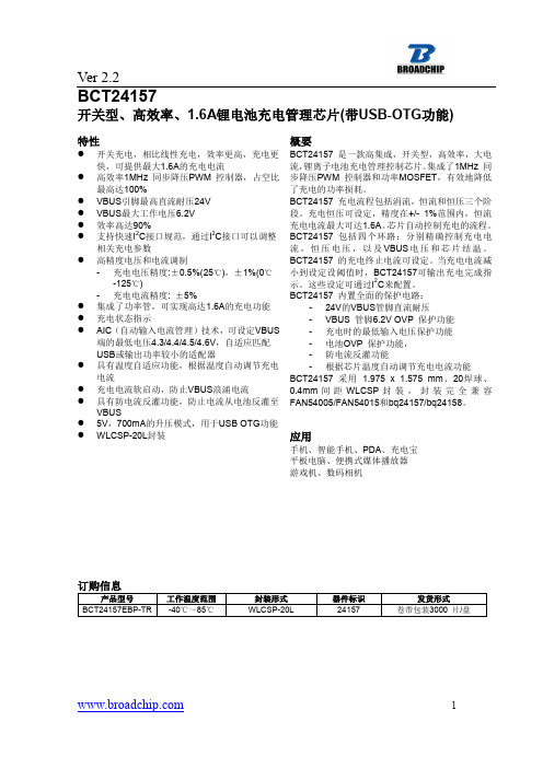
BCT24157_REV2P2_20170511
如果器件工作条件超过上述各项极限值,可能对器件造成永久性损坏。上述参数仅仅是工作条件的极限值,不建议器 件工作在推荐条件以外的情况。器件长时间工作在极限工作条件下,其可靠性及寿命可能受到影响。
5
Ver 2.2
电气特性
除特别说明外,测试条件均为:VBUS=5V,TA=25℃。
VBUS=5V, VBAT=3.6V, IOREG=1600mA No Battery, VBUS at Power UP
OTG MODE波形(CH2=VBUS,CH4=BAT,CH3=SW,CH1=IL)
VBAT=3.6V, IVBUS=500mA Battery Removal/Insertion During Charging
应用
手机、智能手机、PDA、充电宝 平板电脑、便携式媒体播放器 游戏机、数码相机
订购信息
产品型号 BCT24157EBP-TR 工作温度范围 -40℃~85℃ 封装形式 WLCSP-20L 器件标识 24157 发货形式 卷带包装3000 片/盘
VBUS OVP VCC
Q1A Q1B ISNS
POWER OUTPUT STAGE
RSENSE
PGND
Battery
DAC
VREF
CSIN
VBAT
CBAT
SDA SCL
PMID
I2C INTERFACE OSC LOGIC AND CONTROL
STAT 50mA
SYSTEM LOAD
图2
IC 和系统原理框图
1
Ver 2.2
典型应用原理图
手机USB 端口
VBUS SW
L1 1uH
CG2145MS,CG2800MS,CG75MS,CG75LTR,CG2800LTR,CG2600LTR,CG2470L,CG75L, 规格书,Datasheet 资料

CG/CG2 Series
CG/CG2 Series
Description
Littelfuse highly reliable CG/CG2 Series GDTs provide a high degree of surge protection in a small size ideal for board level circuit protection. GDTs function as switches which dissipate a minimum amount of energy and therefore handle currents that far surpass other types of transient voltage protection. Their gas-filled, rugged ceramic metal construction make them well suited to adverse environments. The CG/CG2 series comes in a variety of forms including surface mount, core, straight and shaped leads, to serve a variety of mounting methods.
AGENCY FILE NUMBER
Agency Approvals
AGENCY
& &
2 Electrode GDT Graphical Symbol
The CG Series (75-110V) is ideal for protection of test and communication equipment and other devices in which low voltage limits and extremely low arc voltages are required. The CG2 Series (145V-1000V) is ideal for protecting equipment where higher voltage limits and holdover voltages are necessary.
W25Q128JVSIQ规格书_W25Q128JVSIQ中文资料_W25Q128JVSIQ Datasheet

Publication Release Date: May 02, 2017Revision D3V 128M-BITSERIAL FLASH MEMORY WITH DUAL/QUAD SPI- 1 -Table of Contents1. GENERAL DESCRIPTIONS ............................................................................................................. 42. FEATURES ....................................................................................................................................... 43.PACKAGE TYPES AND PIN CONFIGURATIONS ........................................................................... 5 3.1 Pin Configuration SOIC 208-mil ........................................................................................... 5 3.2 Pad Configuration WSON 6x5-mm/ 8x6-mm ....................................................................... 5 3.3 Pin Description SOIC 208-mil, WSON 6x5-mm / 8x6-mm ................................................... 5 3.4 Pin Configuration SOIC 300-mil ........................................................................................... 6 3.5 Pin Description SOIC 300-mil ............................................................................................... 6 3.6 Ball Configuration TFBGA 8x6-mm (5x5 or 6x4 Ball Array) ................................................. 7 3.7Ball Description TFBGA 8x6-mm ......................................................................................... 7 4. PIN DESCRIPTIONS ........................................................................................................................ 8 4.1 Chip Select (/CS) .................................................................................................................. 8 4.2 Serial Data Input, Output and IOs (DI, DO and IO0, IO1, IO2, IO3) ..................................... 8 4.3 Write Protect (/WP) .............................................................................................................. 8 4.4 HOLD (/HOLD) ..................................................................................................................... 8 4.5 Serial Clock (CLK) ................................................................................................................ 8 4.6Reset (/RESET) (8)5. BLOCK DIAGRAM ............................................................................................................................ 96.FUNCTIONAL DESCRIPTIONS ..................................................................................................... 10 6.1 Standard SPI Instructions ................................................................................................... 10 6.2 Dual SPI Instructions .......................................................................................................... 10 6.3 Quad SPI Instructions ......................................................................................................... 10 6.4 Software Reset & Hardware /RESET pin ........................................................................... 10 6.5Write Protection (11)6.5.1 Write Protect Features (11)7. STATUS AND CONFIGURATION REGISTERS ............................................................................ 12 7.1Status Registers (12)7.1.1 Erase/Write In Progress (BUSY) – Status Only ................................................................ 12 7.1.2 Write Enable Latch (WEL) – Status Only .......................................................................... 12 7.1.3 Block Protect Bits (BP2, BP1, BP0) – Volatile/Non-Volatile Writable ................................ 12 7.1.4 Top/Bottom Block Protect (TB) – Volatile/Non-Volatile Writable ....................................... 13 7.1.5 Sector/Block Protect Bit (SEC) – Volatile/Non-Volatile Writable ....................................... 13 7.1.6 Complement Protect (CMP) – Volatile/Non-Volatile Writable ............................................ 13 7.1.1 Status Register Protect (SRP, SRL) – Volatile/Non-Volatile Writable ............................... 14 7.1.2 Erase/Program Suspend Status (SUS) – Status Only . (15)Publication Release Date: May 02, 2017- 2 - Revision D7.1.3 Security Register Lock Bits (LB3, LB2, LB1) – Volatile/Non-Volatile OTP Writable .......... 15 7.1.4 Quad Enable (QE) – Volatile/Non-Volatile Writable .......................................................... 15 7.1.5 Write Protect Selection (WPS) – Volatile/Non-Volatile Writable ....................................... 16 7.1.6 Output Driver Strength (DRV1, DRV0) – Volatile/Non-Volatile Writable ........................... 16 7.1.7 Reserved Bits – Non Functional ........................................................................................ 16 7.1.8 W25Q128JV Status Register Memory Protection (WPS = 0, CMP = 0) ............................... 17 7.1.9 W25Q128JV Status Register Memory Protection (WPS = 0, CMP = 1) ............................... 18 7.1.10 W25Q128JV Individual Block Memory Protection (WPS=1) . (19)8. INSTRUCTIONS ............................................................................................................................. 20 8.1Device ID and Instruction Set Tables (20)8.1.1 Manufacturer and Device Identification ................................................................................ 20 8.1.2 Instruction Set Table 1 (Standard SPI Instructions)(1)........................................................... 21 8.1.3 Instruction Set Table 2 (Dual/Quad SPI Instructions) ........................................................... 22 Notes: (22)8.2 Instruction Descriptions (23)8.2.1 Write Enable (06h) ............................................................................................................... 23 8.2.2 Write Enable for Volatile Status Register (50h) .................................................................... 23 8.2.3 Write Disable (04h) ............................................................................................................... 24 8.2.4 Read Status Register-1 (05h), Status Register-2 (35h) & Status Register-3 (15h) .............. 24 8.2.5 Write Status Register-1 (01h), Status Register-2 (31h) & Status Register-3 (11h) .............. 25 8.2.6 Read Data (03h) ................................................................................................................... 27 8.2.7 Fast Read (0Bh) ................................................................................................................... 28 8.2.8 Fast Read Dual Output (3Bh) ............................................................................................... 29 8.2.9 Fast Read Quad Output (6Bh) .............................................................................................. 30 8.2.10 Fast Read Dual I/O (BBh) ................................................................................................... 31 8.2.11 Fast Read Quad I/O (EBh) ................................................................................................. 32 8.2.12 Set Burst with Wrap (77h) .................................................................................................. 34 8.2.13 Page Program (02h) ........................................................................................................... 35 8.2.14 Quad Input Page Program (32h) ........................................................................................ 36 8.2.15 Sector Erase (20h) ............................................................................................................. 37 8.2.16 32KB Block Erase (52h) ..................................................................................................... 38 8.2.17 64KB Block Erase (D8h) ..................................................................................................... 39 8.2.18 Chip Erase (C7h / 60h) ....................................................................................................... 40 8.2.19 Erase / Program Suspend (75h) ......................................................................................... 41 8.2.20 Erase / Program Resume (7Ah) ......................................................................................... 42 8.2.21 Power-down (B9h) .............................................................................................................. 43 8.2.22 Release Power-down / Device ID (ABh) ............................................................................. 44 8.2.23 Read Manufacturer / Device ID (90h) ................................................................................. 45 8.2.24 Read Manufacturer / Device ID Dual I/O (92h) ................................................................... 46 8.2.25 Read Manufacturer / Device ID Quad I/O (94h) ................................................................. 47 8.2.26 Read Unique ID Number (4Bh). (48)- 3 -8.2.27 Read JEDEC ID (9Fh) ........................................................................................................ 49 8.2.28 Read SFDP Register (5Ah) ................................................................................................ 50 8.2.29 Erase Security Registers (44h) ........................................................................................... 51 8.2.30 Program Security Registers (42h) ...................................................................................... 52 8.2.31 Read Security Registers (48h) ........................................................................................... 53 8.2.32 Individual Block/Sector Lock (36h) ..................................................................................... 54 8.2.33 Individual Block/Sector Unlock (39h) .................................................................................. 55 8.2.34 Read Block/Sector Lock (3Dh) ........................................................................................... 56 8.2.35 Global Block/Sector Lock (7Eh) .......................................................................................... 57 8.2.36 Global Block/Sector Unlock (98h) ....................................................................................... 57 8.2.37 Enable Reset (66h) and Reset Device (99h) . (58)9.ELECTRICAL CHARACTERISTICS (59)9.1 Absolute Maximum Ratings (1) ............................................................................................ 59 9.2 Operating Ranges............................................................................................................... 59 9.3 Power-Up Power-Down Timing and Requirements ............................................................ 60 9.4 DC Electrical Characteristics- ............................................................................................. 61 9.5 AC Measurement Conditions .............................................................................................. 62 9.6 AC Electrical Characteristics (6) ........................................................................................... 63 9.7 Serial Output Timing ........................................................................................................... 65 9.8 Serial Input Timing .............................................................................................................. 65 9.9/WP Timing ......................................................................................................................... 65 10. PACKAGE SPECIFICATIONS ........................................................................................................ 66 10.1 8-Pin SOIC 208-mil (Package Code S) .............................................................................. 66 10.2 16-Pin SOIC 300-mil (Package Code F) ............................................................................ 67 10.3 8-Pad WSON 6x5-mm (Package Code P) ......................................................................... 68 10.4 8-Pad WSON 8x6-mm (Package Code E) ......................................................................... 69 10.5 24-Ball TFBGA 8x6-mm (Package Code B, 5x5-1 ball array) ............................................ 70 10.624-Ball TFBGA 8x6-mm (Package Code C, 6x4 ball array) ............................................... 71 11. ORDERING INFORMATION .......................................................................................................... 72 11.1Valid Part Numbers and Top Side Marking (73)12. REVISION HISTORY (74)Publication Release Date: May 02, 2017- 4 - Revision D1. GENERAL DESCRIPTIONSThe W25Q128JV (128M-bit) Serial Flash memory provides a storage solution for systems with limited space, pins and power. The 25Q series offers flexibility and performance well beyond ordinary Serial Flash devices. They are ideal for code shadowing to RAM, executing code directly from Dual/Quad SPI (XIP) and storing voice, text and data. The device operates on a single 2.7V to 3.6V power supply with current consumption as low as 1µA for power-down. All devices are offered in space-saving packages.The W25Q128JV array is organized into 65,536 programmable pages of 256-bytes each. Up to 256 bytes can be programmed at a time. Pages can be erased in groups of 16 (4KB sector erase), groups of 128 (32KB block erase), groups of 256 (64KB block erase) or the entire chip (chip erase). The W25Q128JV has 4,096 erasable sectors and 256 erasable blocks respectively. The small 4KB sectors allow for greater flexibility in applications that require data and parameter storage. (See Figure 2.)The W25Q128JV supports the standard Serial Peripheral Interface (SPI), Dual/Quad I/O SPI: Serial Clock, Chip Select, Serial Data I/O0 (DI), I/O1 (DO), I/O2 and I/O3. SPI clock frequencies of W25Q128JV of up to 133MHz are supported allowing equivalent clock rates of 266MHz (133MHz x 2) for Dual I/O and 532MHz (133MHz x 4) for Quad I/O when using the Fast Read Dual/Quad I/O. These transfer rates can outperform standard Asynchronous 8 and 16-bit Parallel Flash memories.Additionally, the device supports JEDEC standard manufacturer and device ID and SFDP, and a 64-bit Unique Serial Number and three 256-bytes Security Registers.2. FEATURES∙ New Family of SpiFlash Memories – W25Q128JV: 128M-bit / 16M-byte – Standard SPI: CLK, /CS, DI, DO – Dual SPI: CLK, /CS, IO 0, IO 1 – Quad SPI: CLK, /CS, IO 0, IO 1, IO 2, IO 3 – Software & Hardware Reset (1) ∙ Highest Performance Serial Flash – 133MHz Single, Dual/Quad SPI clocks – 266/532MHz equivalent Dual/Quad SPI – 66MB/S continuous data transfer rate – Min. 100K Program-Erase cycles per sector – More than 20-year data retention ∙ Efficient “Continuous Read”– Continuous Read with 8/16/32/64-Byte Wrap– As few as 8 clocks to address memory– Allows true XIP (execute in place) operation ∙ Low Power, Wide Temperature Range– Single 2.7 to 3.6V supply– <1µA Power-down (typ.)– -40°C to +85°C operating range∙ Flexible Architecture with 4KB sectors – Uniform Sector/Block Erase (4K/32K/64K-Byte) – Program 1 to 256 byte per programmable page – Erase/Program Suspend & Resume ∙ Advanced Security Features – Software and Hardware Write-Protect – Power Supply Lock-Down – Special OTP protection – Top/Bottom, Complement array protection – Individual Block/Sector array protection – 64-Bit Unique ID for each device – Discoverable Parameters (SFDP) Register– 3X256-Bytes Security Registers with OTP locks – Volatile & Non-volatile Status Register Bits ∙ Space Efficient Packaging – 8-pin SOIC 208-mil– 16-pin SOIC 300-mil (additional /RESET pin) – 8-pad WSON 6x5-mm / 8x6-mm – 24-ball TFBGA 8x6-mm (6x4/5x5 ball array) – Contact Winbond for KGD and other options Note: 1. Hardware /RESET pin is only available on TFBGA or SOIC16 packages- 5 -3. PACKAGE TYPES AND PIN CONFIGURATIONS3.1 Pin Configuration SOIC 208-milFigure 1a. W25Q128JV Pin Assignments, 8-pin SOIC 208-mil (Package Code S)3.2 Pad Configuration WSON 6x5-mm/ 8x6-mmFigure 1b. W25Q128JV Pad Assignments, 8-pad WSON 6x5-mm/ 8x6-mm (Package Code P/E)3.3 Pin Description SOIC 208-mil, WSON 6x5-mm / 8x6-mmNotes:1. IO0 and IO1 are used for Standard and Dual SPI instructions2.IO0 – IO3 are used for Quad SPI instructions, /HOLD (or /RESET) function is only available for Standard/Dual SPI.Publication Release Date: May 02, 2017- 6 - Revision D3.4 Pin Configuration SOIC 300-milFigure 1c. W25Q128JV Pin Assignments, 16-pin SOIC 300-mil (Package Code F)3.5 Pin Description SOIC 300-milNotes:1. IO0 and IO1 are used for Standard and Dual SPI instructions.2. IO0 – IO3 are used for Quad SPI instructions, /HOLD (or /RESET) function is only available for Standard/Dual SPI.3. The /RESET pin is a dedicated hardware reset pin regardless of device settings or operation states. If the hardware reset function is not used, this pin can be left floating or connected to VCC in the system.3.6Ball Configuration TFBGA 8x6-mm (5x5 or 6x4 Ball Array)Figure 1d. W25Q128JV Ball Assignments, 24-ball TFBGA 8x6-mm (Package Code B/C)3.7Ball Description TFBGA 8x6-mmNotes:1.IO0 and IO1 are used for Standard and Dual SPI instructions2.IO0 – IO3 are used for Quad SPI instructions, /HOLD (or /RESET) function is only available for Standard/Dual SPI.3. The /RESET pin is a dedicated hardware reset pin regardless of device settings or operation states.If the hardware reset function is not used, this pin can be left floating or connected to VCC in the system- 7 -Publication Release Date: May 02, 2017- 8 - Revision D4. PIN DESCRIPTIONS4.1 Chip Select (/CS)The SPI Chip Select (/CS) pin enables and disables device operation. When /CS is high the device is deselected and the Serial Data Output (DO, or IO0, IO1, IO2, IO3) pins are at high impedance. When deselected, the devices power consumption will be at standby levels unless an internal erase, program or write status register cycle is in progress. When /CS is brought low the device will be selected, power consumption will increase to active levels and instructions can be written to and data read from the device. After power-up, /CS must transition from high to low before a new instruction will be accepted. The /CS input must track the VCC supply level at power-up and power-down (see “Write Protection” and Figure 58). If needed a pull-up resister on the /CS pin can be used to accomplish this.4.2 Serial Data Input, Output and IOs (DI, DO and IO0, IO1, IO2, IO3)The W25Q128JV supports standard SPI, Dual SPI and Quad SPI operation. Standard SPI instructions use the unidirectional DI (input) pin to serially write instructions, addresses or data to the device on the rising edge of the Serial Clock (CLK) input pin. Standard SPI also uses the unidirectional DO (output) to read data or status from the device on the falling edge of CLK.Dual and Quad SPI instructions use the bidirectional IO pins to serially write instructions, addresses or data to the device on the rising edge of CLK and read data or status from the device on the falling edge of CLK. Quad SPI instructions require the non-volatile Quad Enable bit (QE) in Status Register-2 to be set. When QE=1, the /WP pin becomes IO2 and the /HOLD pin becomes IO3.4.3 Write Protect (/WP)The Write Protect (/WP) pin can be used to prevent the Status Register from being written. Used in conjunction with the Status Register’s Block Protect (CMP, SEC, TB, BP2, BP1 and BP0) bits and Status Register Protect (SRP) bits, a portion as small as a 4KB sector or the entire memory array can be hardware protected. The /WP pin is active low.4.4 HOLD (/HOLD)The /HOLD pin allows the device to be paused while it is actively selected. When /HOLD is brought low, while /CS is low, the DO pin will be at high impedance and signals on the DI and CLK pins will be ignored (don’t care). When /HOLD is brought high, device operation can resume. The /HOLD function can be useful when multiple devices are sharing the same SPI signals. The /HOLD pin is active low. When the QE bit of Status Register-2 is set for Quad I/O, the /HOLD pin function is not available since this pin is used for IO3. See Figure 1a-c for the pin configuration of Quad I/O operation.4.5 Serial Clock (CLK)The SPI Serial Clock Input (CLK) pin provides the timing for serial input and output operations. ("See SPI Operations")4.6 Reset (/RESET)A dedicated hardware /RESET pin is available on SOIC-16 and TFBGA packages. When it’s driven low for a minimum period of ~1µS, this device will terminate any external or internal operations and return to its power-on state.Note: Hardware /RESET pin is available on SOIC-16 or TFBGA; please contact Winbond for this package.- 9 -5. BLOCK DIAGRAMFigure 2. W25Q128JV Serial Flash Memory Block Diagram6.FUNCTIONAL DESCRIPTIONS6.1Standard SPI InstructionsThe W25Q128JV is accessed through an SPI compatible bus consisting of four signals: Serial Clock (CLK), Chip Select (/CS), Serial Data Input (DI) and Serial Data Output (DO). Standard SPI instructions use the DI input pin to serially write instructions, addresses or data to the device on the rising edge of CLK. The DO output pin is used to read data or status from the device on the falling edge of CLK.SPI bus operation Mode 0 (0,0) and 3 (1,1) are supported. The primary difference between Mode 0 and Mode 3 concerns the normal state of the CLK signal when the SPI bus master is in standby and data is not being transferred to the Serial Flash. For Mode 0, the CLK signal is normally low on the falling and rising edges of /CS. For Mode 3, the CLK signal is normally high on the falling and rising edges of /CS.6.2Dual SPI InstructionsThe W25Q128JV supports Dual SPI operation when using instructions such as “Fast Read Dual Output (3Bh)” and “Fast Read Dual I/O (BBh)”. These instructions allow data to be transferred to or from the device at two to three times the rate of ordinary Serial Flash devices. The Dual SPI Read instructions are ideal for quickly downloading code to RAM upon power-up (code-shadowing) or for executing non-speed-critical code directly from the SPI bus (XIP). When using Dual SPI instructions, the DI and DO pins become bidirectional I/O pins: IO0 and IO1.6.3Quad SPI InstructionsThe W25Q128JV supports Quad SPI operation when using instructions such as “Fast Read Quad Output (6Bh)”,and “Fast Read Quad I/O (EBh). These instructions allow data to be transferred to or from the device four to six times the rate of ordinary Serial Flash. When using Quad SPI instructions, the DI and DO pins become bidirectional IO0 and IO1, with the additional I/O pins: IO2, IO3.6.4Software Reset & Hardware /RESET pinThe W25Q128JV can be reset to the initial power-on state by a software Reset sequence. This sequence must include two consecutive instructions: Enable Reset (66h) & Reset (99h). If the instruction sequence is successfully accepted, the device will take approximately 30µS (t RST)to reset. No instruction will be accepted during the reset period. For the SOIC-16 and TFBGA packages, W25Q128JV provides a dedicated hardware /RESET pin. Drive the /RESET pin low for a minimum period of ~1µS (tRESET*) will interrupt any on-going external/internal operations and reset the device to its initial power-on state. Hardware /RESET pin has higher priority than other SPI input signals (/CS, CLK, IOs).Note:1.Hardware /RESET pin is available on SOIC-16 or TFBGA; please contact Winbond for his package.2.While a faster /RESET pulse (as short as a few hundred nanoseconds) will often reset the device, a 1us minimum isrecommended to ensure reliable operation.3.There is an internal pull-up resistor for the dedicated /RESET pin on the SOIC-16 and TFBGA-24 package. If the reset functionis not needed, this pin can be left floating in the system.6.5Write ProtectionApplications that use non-volatile memory must take into consideration the possibility of noise and other adverse system conditions that may compromise data integrity. To address this concern, the W25Q128JV provides several means to protect the data from inadvertent writes.6.5.1Write Protect Features∙Device resets when VCC is below threshold∙Time delay write disable after Power-up∙Write enable/disable instructions and automatic write disable after erase or program∙Software and Hardware (/WP pin) write protection using Status Registers∙Additional Individual Block/Sector Locks for array protection∙Write Protection using Power-down instruction∙Lock Down write protection for Status Register until the next power-up∙One Time Program (OTP) write protection for array and Security Registers using Status Register** Note:This feature is available upon special order. Please contact Winbond for details.Upon power-up or at power-down, the W25Q128JV will maintain a reset condition while VCC is below the threshold value of V WI, (See Power-up Timing and Voltage Levels and Figure 43). While reset, all operations are disabled and no instructions are recognized. During power-up and after the VCC voltage exceeds V WI, all program and erase related instructions are further disabled for a time delay of t PUW. This includes the Write Enable, Page Program, Sector Erase, Block Erase, Chip Erase and the Write Status Register instructions. Note that the chip select pin (/CS) must track the VCC supply level at power-up until the VCC-min level and t VSL time delay is reached, and it must also track the VCC supply level at power-down to prevent adverse command sequence. If needed a pull-up resister on /CS can be used to accomplish this.After power-up the device is automatically placed in a write-disabled state with the Status Register Write Enable Latch (WEL) set to a 0. A Write Enable instruction must be issued before a Page Program, Sector Erase, Block Erase, Chip Erase or Write Status Register instruction will be accepted. After completing a program, erase or write instruction the Write Enable Latch (WEL) is automatically cleared to a write-disabled state of 0.Software controlled write protection is facilitated using the Write Status Register instruction and setting the Status Register Protect (SRP, SRL) and Block Protect (CMP, TB, BP[3:0]) bits. These settings allow a portion or the entire memory array to be configured as read only. Used in conjunction with the Write Protect (/WP) pin, changes to the Status Register can be enabled or disabled under hardware control. See Status Register section for further information. Additionally, the Power-down instruction offers an extra level of write protection as all instructions are ignored except for the Release Power-down instruction.The W25Q128JV also provides another Write Protect method using the Individual Block Locks. Each 64KB block (except the top and bottom blocks, total of 126 blocks) and each 4KB sector within the top/bottom blocks (total of 32 sectors) are equipped with an Individual Block Lock bit. When the lock bit is 0, the corresponding sector or block can be erased or programmed; when the lock bit is set to 1, Erase or Program commands issued to the corresponding sector or block will be ignored. When the device is powered on, all Individual Block Lock bits will be 1, so the entire memory array is protected from Erase/Program. An “Individual Block Unlock (39h)” instruction must be issued to unlock any specific sector or block.The WPS bit in Status Register-3 is used to decide which Write Protect scheme should be used. When WPS=0 (factory default), the device will only utilize CMP, SEC, TB, BP[2:0] bits to protect specific areas of the array; when WPS=1, the device will utilize the Individual Block Locks for write protection.。
易用型逻辑PM2120电能表说明书
T h e i n f o r m a t i o n p r o v i d e d i n t h i s d o c u m e n t a t i o n c o n t a i n s g e n e r a l d e s c r i p t i o n s a n d /o r t e c h n i c a l c h a r a c t e r i s t i c s o f t h e p e r f o r m a n c e o f t h e p r o d u c t s c o n t a i n e d h e r e i n .T h i s d o c u m e n t a t i o n i s n o t i n t e n d e d a s a s u b s t i t u t e f o r a n d i s n o t t o b e u s e d f o r d e t e r m i n i n g s u i t a b i l i t y o r r e l i a b i l i t y o f t h e s e p r o d u c t s f o r s p e c i f i c u s e r a p p l i c a t i o n s .I t i s t h e d u t y o f a n y s u c h u s e r o r i n t e g r a t o r t o p e r f o r m t h e a p p r o p r i a t e a n d c o m p l e t e r i s k a n a l y s i s , e v a l u a t i o n a n d t e s t i n g o f t h e p r o d u c t s w i t h r e s p e c t t o t h e r e l e v a n t s p e c i f i c a p p l i c a t i o n o r u s e t h e r e o f .N e i t h e r S c h n e i d e r E l e c t r i c I n d u s t r i e s S A S n o r a n y o f i t s a f f i l i a t e s o r s u b s i d i a r i e s s h a l l b e r e s p o n s i b l e o r l i a b l e f o r m i s u s e o f t h e i n f o r m a t i o n c o n t a i n e d h e r e i n .Product data sheetCharacteristicsMETSEPM2120EasyLogic PM2120, Power & Energy meter,up to the 15th harmonic, LED display, RS485,class 1MainRange EasyLogic Product name EasyLogic PM2100Device short name PM2120Product or component typePower meterComplementaryDevice application Sub billingPower monitoring Power quality analysis Total harmonic distortion Up to the 15th harmonicType of measurementApparent power min/max, totalActive and reactive power min/max, total Current min/max, avg Voltage min/max, avg Frequency min/max, avgTotal current harmonic distortion THD (I) per phase Total voltage harmonic distortion THD (U) per phase Power factor min/max, avg Apparent energy totalActive and reactive energy totalMetering typeCurrent I, I1, I2, I3Peak demand power PM, QM, SMActive, reactive, apparent energy (signed, four quadrant)Peak demand currents Active power P, P1, P2, P3Calculated neutral currentVoltage U, U21, U32, U13, V, V1, V2, V3Unbalance currentReactive power Q, Q1, Q2, Q3Demand power P, Q, SApparent power S, S1, S2, S3Accuracy classClass 1 active energy conforming to IEC 62053-21Class 1 reactive energy conforming to IEC 62053-24Class 5 harmonic distorsion (I THD & U THD)Measurement accuracyApparent power +/- 1 %Active energy +/- 1 %Reactive energy +/- 1 %Active power +/- 1 %Voltage +/- 0.5 %Power factor +/- 0.01Current +/- 0.5 %Frequency +/- 0.05 %Measurement current 5…6000 mAMeasurement voltage35…480 V AC 50/60 Hz between phases20…277 V AC 50/60 Hz between phase and neutral 480…999000 V AC 50/60 Hz with external VT Frequency measurement range 45…65 Hz[Us] rated supply voltage44...277 V AC 45...65 Hz +/- 10 %44...277 V DC +/- 10 %Network frequency50 Hz60 HzRide-through time100 Ms 120 V AC typical400 Ms 230 V AC typical50 ms 125 V DC typicalLine Rated Current1 A5 AMaximum power consumption in VA6 VA 277 V ACMaximum power consumption in W 3.3 W (power lines (AC))2 W at 277 V (power lines (DC))Input impedance Current (impedance <= 0.3 mOhm)Voltage (impedance > 5 MOhm)Tamperproof of settings Protected by access codeDisplay type7 segments LEDDisplay colour RedMessages display capacity 3 fields of 4 charactersDisplay digits12 - 0.56 in (14.2 mm)Demand intervals Configurable from 1 to 60 minInformation displayed Demand current (past value)Demand current (present value)Demand power (past value)Demand power (present value)VoltageCurrentFrequencyEnergy consumptionHarmonic distortionPower factorActive powerApparent powerReactive powerUnbalanced in %Control type 3 x buttonLocal signalling Red LED: output signal 1...9999000 pulse/ k_h (kWh, kVAh, kVARh)Green LED: module operation and integrated communicationNumber of inputs0Number of outputs0Communication port protocol Modbus RTU 4800 bps, 9600 bps, 19200 bps, 38.4 Kbps even/odd or none - 2wires 2500 VCommunication port support Screw terminal block: RS485Data recording Time stampingMin/max for 8 parametersFunction available Real time clockSampling rate64 samples/cycleCybersecurity Enable/disable communication portsCommunication service Remote monitoringProduct certifications CE IEC 61010-1CULus UL 61010-1CULus conforming to CSA C22.2 No 61010-1RCMEACC-TickMounting mode Clip-onMounting position VerticalMounting support FrameworkProvided equipment 1 x Installation guideMeasurement category Category III 480 VCategory II 480…600 VElectrical insulation class Double insulationClass IIFlame retardance V-0 conforming to UL 94Connections - terminals Current transformer screw connection bottom) 6Voltage inputs screw connection top) 4Material PolycarbonateWidth 3.78 in (96 mm)Depth Total 3.00 in (76.09 mm)Embedded 2.43 in (61.64 mm)Height 3.78 in (96 mm)Net Weight10.58 oz (300 g)Compatibility code PM2120EnvironmentService life7 year(s)IP degree of protection IP54 front: conforming to IEC 60529Body IP30 IEC 60529Relative humidity5…95 % 122 °F (50 °C)Pollution degree2Ambient air temperature for operation14…140 °F (-10…60 °C)Ambient air temperature for storage-13…158 °F (-25…70 °C)Operating altitude<= 6561.68 ft (2000 m)Electromagnetic compatibility Electrostatic discharge conforming to IEC 61000-4-2Radiated radio-frequency electromagnetic field immunity test IEC 61000-4-3Electrical fast transient/burst immunity test conforming to IEC 61000-4-4Surge immunity test IEC 61000-4-5Conducted RF disturbances conforming to IEC 61000-4-6Magnetic field at power frequency conforming to IEC 61000-4-8Voltage dips and interruptions immunity test IEC 61000-4-11Emission tests conforming to FCC part 15 class AOvervoltage category IIIOrdering and shipping detailsGTIN03606480800146Nbr. of units in pkg.1Package weight(Lbs)10.67 oz (302.5 g)Packing UnitsUnit Type of Package 1PCEPackage 1 Height 3.78 in (9.6 cm)Package 1 width 2.65 in (6.72 cm)Package 1 Length 4.00 in (10.16 cm)Unit Type of Package 2BB1Number of Units in Package 21Package 2 Weight14.25 oz (404 g)Package 2 Height 4.53 in (11.5 cm)Package 2 width 3.43 in (8.7 cm)Package 2 Length 4.72 in (12 cm)Unit Type of Package 3S03Number of Units in Package 318Package 3 Weight17.04 lb(US) (7.73 kg)Package 3 Height11.81 in (30 cm)Package 3 width11.81 in (30 cm)Package 3 Length15.75 in (40 cm)Offer SustainabilitySustainable offer status Green Premium productREACh Regulation REACh DeclarationEU RoHS Directive Compliant EU RoHS DeclarationMercury free YesRoHS exemption information YesChina RoHS Regulation China RoHS DeclarationEnvironmental Disclosure Product Environmental Profile Circularity Profile End Of Life Information。
半导体传感器ADUM1401BRWZ中文规格书

Data SheetADuM1400/ADuM1401/ADuM1402 Rev. L | Page 9 of 31 ParameterSymbol Min Typ Max Unit Test Conditions 90 Mbps (CRW Grade Only)V DD1 Supply CurrentI DD1 (90) 5 V/3 V Operation57 82 mA 45 MHz logic signal freq. 3 V/5 V Operation30 52 mA 45 MHz logic signal freq. V DD2 Supply CurrentI DD2 (90) 5 V/3 V Operation18 27 mA 45 MHz logic signal freq. 3 V/5 V Operation31 43 mA 45 MHz logic signal freq. ADuM1402 Total Supply Current, Four Channels 2DC to 2 MbpsV DD1 Supply CurrentI DD1 (Q) 5 V/3 V Operation1.52.1 mA DC to 1 MHz logic signal freq. 3 V/5 V Operation0.9 1.5 mA DC to 1 MHz logic signal freq. V DD2 Supply CurrentI DD2 (Q) 5 V/3 V Operation0.9 1.5 mA DC to 1 MHz logic signal freq. 3 V/5 V Operation1.52.1 mA DC to 1 MHz logic signal freq. 10 Mbps (BRW and CRW Grades Only)V DD1 Supply CurrentI DD1 (10) 5 V/3 V Operation5.6 7.0 mA 5 MHz logic signal freq. 3 V/5 V Operation3.04.2 mA 5 MHz logic signal freq. V DD2 Supply CurrentI DD2 (10) 5 V/3 V Operation3.04.2 mA 5 MHz logic signal freq. 3 V/5 V Operation5.6 7.0 mA 5 MHz logic signal freq. 90 Mbps (CRW Grade Only)V DD1 Supply CurrentI DD1 (90) 5 V/3 V Operation44 62 mA 45 MHz logic signal freq. 3 V/5 V Operation24 39 mA 45 MHz logic signal freq. V DD2 Supply CurrentI DD2 (90) 5 V/3 V Operation24 39 mA 45 MHz logic signal freq. 3 V/5 V Operation44 62 mA 45 MHz logic signal freq. For All ModelsInput CurrentsI IA , I IB , I IC , I ID , I E1, I E2 −10 +0.01 +10 µA 0 V ≤ V IA , V IB , V IC , V ID ≤ V DD1 or V DD2, 0 V ≤ V E1, V E2 ≤ V DD1 or V DD2 Logic High Input ThresholdV IH , V EH 5 V/3 V Operation2.0 V 3 V/5 V Operation1.6 V Logic Low Input ThresholdV IL , V EL 5 V/3 V Operation0.8 V 3 V/5 V Operation0.4 V Logic High Output VoltagesV OAH , V OBH , V OCH , V ODH (V DD1 or V DD2) − 0.1 (V DD1 or V DD2) V I Ox = −20 µA, V Ix = V IxH (V DD1 or V DD2) − 0.4(V DD1 or V DD2) − 0.2 V I Ox = −3.2 mA, V Ix = V IxH Logic Low Output Voltages V OAL , V OBL ,V OCL , V ODL 0.0 0.1V I Ox = 20 µA, V Ix = V IxL 0.04 0.1V I Ox = 400 µA, V Ix = V IxL0.2 0.4 V I Ox = 3.2 mA, V Ix = V IxLSWITCHING SPECIFICATIONSADuM1400ARW /ADuM1401ARW /ADuM1402ARWMinimum Pulse Width 3PW 1000 ns C L = 15 pF, CMOS signal levels Maximum Data Rate 41 Mbps C L = 15 pF, CMOS signal levels Propagation Delay 5t PHL , t PLH 50 70 100 ns C L = 15 pF, CMOS signal levels Pulse Width Distortion, |t PLH − t PHL |5PWD 40 ns C L = 15 pF, CMOS signal levels Change vs. Temperature11 ps/°C C L = 15 pF, CMOS signal levels Propagation Delay Skew 6t PSK 50 ns C L = 15 pF, CMOS signal levels Channel-to-Channel Matching 7t PSKCD /t PSKOD 50 ns C L = 15 pF, CMOS signal levels ADuM1400BRW /ADuM1401BRW /ADuM1402BRWMinimum Pulse Width 3PW 100 ns C L = 15 pF, CMOS signal levels Maximum Data Rate 410 Mbps C L = 15 pF, CMOS signal levelsPropagation Delay 5 t PHL , t PLH 15 35 50 ns C L = 15 pF, CMOS signal levelsData SheetADuM1400/ADuM1401/ADuM1402 Rev. L | Page 13 of 31ELECTRICAL CHARACTERISTICS—3 V, 125°C OPERATION 1 3.0 V ≤ V DD1 ≤ 3.6 V , 3.0 V ≤ V DD2 ≤ 3.6 V; all minimum/maximum specifications apply over the entire recommended operation range, unless otherwise noted; all typical specifications are at T A = 25°C, V DD1 = V DD2 = 3.0 V . These specifications apply to ADuM1400W , ADuM1401W , and ADuM1402W automotive grade versions. Table 5.ParameterSymbol Min Typ Max Unit Test Conditions DC SPECIFICATIONSInput Supply Current per Channel,QuiescentI DDI (Q) 0.26 0.31 mA Output Supply Current per Channel,QuiescentI DDO (Q) 0.11 0.14 mA ADuM1400W , Total Supply Current, FourChannels 2DC to 2 MbpsV DD1 Supply CurrentI DD1 (Q) 1.2 1.9 mA DC to 1 MHz logic signal freq. V DD2 Supply CurrentI DD2 (Q) 0.5 0.9 mA DC to 1 MHz logic signal freq. 10 Mbps (TRWZ Grade Only)V DD1 Supply CurrentI DD1 (10) 4.5 6.5 mA 5 MHz logic signal freq. V DD2 Supply CurrentI DD2 (10) 1.4 2.0 mA 5 MHz logic signal freq. ADuM1401W , Total Supply Current, Four Channels 2DC to 2 MbpsV DD1 Supply CurrentI DD1 (Q) 1.0 1.6 mA DC to 1 MHz logic signal freq. V DD2 Supply CurrentI DD2 (Q) 0.7 1.2 mA DC to 1 MHz logic signal freq. 10 Mbps (TRWZ Grade Only)V DD1 Supply CurrentI DD1 (10) 3.7 5.4 mA 5 MHz logic signal freq. V DD2 Supply CurrentI DD2 (10) 2.2 3.0 mA 5 MHz logic signal freq. ADuM1402W , Total Supply Current, FourChannels 2DC to 2 MbpsV DD1 or V DD2 Supply CurrentI DD1 (Q), I DD2 (Q) 0.9 1.5 mA DC to 1 MHz logic signal freq. 10 Mbps (TRWZ Grade Only)V DD1 or V DD2 Supply CurrentI DD1 (10), I DD2 (10) 3.0 4.2 mA 5 MHz logic signal freq. For All ModelsInput CurrentsI IA , I IB , I IC , I ID , I E1, I E2 −10 +0.01+10µA 0 V ≤ V IA , V IB , V IC , V ID ≤ V DD1 or V DD2, 0 V ≤ V E1, V E2 ≤ V DD1 or V DD2 Logic High Input ThresholdV IH , V EH 1.6 V Logic Low Input ThresholdV IL , V EL 0.4 V Logic High Output VoltagesV OAH , V OBH , V OCH , V ODH (V DD1 or V DD2) − 0.1 3.0 V I Ox = −20 µA, V Ix = V IxH (V DD1 or V DD2) − 0.4 2.8 V I Ox = −3.2 mA, V Ix = V IxH Logic Low Output Voltages V OAL , V OBL ,V OCL , V ODL 0.0 0.1 V I Ox = 20 µA, V Ix = V IxL 0.04 0.1 VI Ox = 400 µA, V Ix = V IxL0.2 0.4 V I Ox = 3.2 mA, V Ix = V IxLSWITCHING SPECIFICATIONSADuM1400WSRWZ /ADuM1401WSRWZ /ADuM1402WSRWZMinimum Pulse Width 3PW 1000 ns C L = 15 pF, CMOS signal levels Maximum Data Rate 41 Mbps C L = 15 pF, CMOS signal levels Propagation Delay 5t PHL , t PLH 50 75 100 ns C L = 15 pF, CMOS signal levels Pulse Width Distortion, |t PLH − t PHL |5PWD 40 ns C L = 15 pF, CMOS signal levels Propagation Delay Skew 6t PSK50 ns C L = 15 pF, CMOS signal levelsChannel-to-Channel Matching 7 t PSKCD /t PSKOD 50 ns C L = 15 pF, CMOS signal levels。
AD5755中文手册

产品聚焦
1. 用于热管理的动态电源控制 2. 16位性能 3. 多通道
应用
过程控制 执行器控制 PLC(可编程控制器)
配套产品
产品系列:AD5755-1、AD5757 外部基准电压源:ADR445、ADR02 数字隔离器:ADuM1410、ADuM1411 电源:ADP2302、ADP2303 其他配套产品参见AD5755产品页面
四通道、16位、串行输入、4-20 mA和 电压输出DAC,提供动态电源控制
AD5755
特性
16位分辨率和单调性 用于热管理的动态电源控制 电流和电压输出引脚可连接到一个引脚 电流输出范围:0 mA至20 mA、4 mA至20 mA或0 mA至 24 mA 总不可调整误差(TUE):±0.05%(最大值) 电压输出范围(含20%超量程):0 V至5 V、0 V至10 V、±5 V和±10 V 总不可调整误差(TUE):±0.04%(最大值) 用户可编程失调与增益 片内诊断 片内基准电压源(±10 ppm/°C,最大值) 温度范围:−40°C至+105°C 至+33V电源供电。在电流模式下,片内动态电源控制功能 利用一个针对最小片内功耗而优化的DC-DC升压转换器, 在7.4 V至29.5 V范围内调节输出驱动器的电压,使封装功 耗最小。 该器件采用多功能三线式串行接口,能够以最高30MHz的 时钟速率工作,并与标准SPI、QSPI™、MICROWIRE™、 DSP和 微 控 制 器 接 口 标 准 兼 容 。 该 接 口 还 提 供 可 选 的 CRC-8分组错误校验功能,以及用于监控接口活动的看门 狗定时器。
ADI中文版数据手册是英文版数据手册的译文,敬请谅解翻译中可能存在的语言组织或翻译错误,ADI不对翻译中存在的差异或由此产生的错误负责。如需确认任何词语的准确性,请参考ADI提 供的最新英文版数据手册。
DA227TL;中文规格书,Datasheet资料
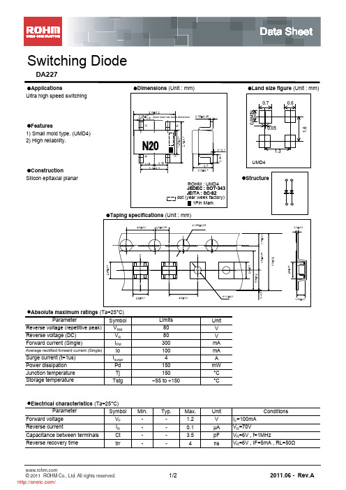
Ta=25℃ VR=6V IF=5mA RL=50Ω n=10pcs
4 3 2 1 0 1
Ifsm 8.3ms 8.3ms 1cyc
10
5 AVE:3.50A 0 IFSM DISRESION MAP
trr DISPERSION MAP
10 NUMBER OF CYCLES IFSM-CYCLE CHARACTERISTICS
0.6
1.25±0.1
2.1±0.1
Features 1) Small mold type. (UMD4) 2) High reliability.
(3)
0~0.1 (4) 0.65 0.65 0.7 0.9±0.1 (1)
1.3
UMD4
Construction Silicon epitaxial planar
Data Sheet
Switching Diode
DA227
Applications Ultra high speed switching Dimensions (Unit : mm) Land size figure (Unit : mm) 0.7
2.0±0.2 各リードとも 0.25± 0.1 0.05 Each lead has same dimension 同寸法 0.15±0.05
Min. -
Typ. -
Max. 1.2 0.1 3.5 4
Unit V μA pF ns IF=100mA VR=70V
Conditions
VR=6V , f=1MHz VR=6V , IF=5mA , RL=50Ω
© 2011 ROHM Co., Ltd. All rights reserved.
MIC2075-2YM;MIC2025-1YMM;MIC2075-1YM;MIC2025-2YM;MIC2025-1YM;中文规格书,Datasheet资料
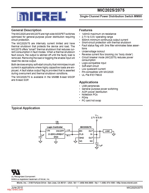
Single-Channel Power Distribution Switch MM8®General Description The MIC2025 and MIC2075 are high-side MOSFET switches optimized for general-purpose power distribution requiring circuit protection.The MIC2025/75 are internally current limited and have thermal shutdown that protects the device and load. The MIC2075 offers “smart” thermal shutdown that reduces cur-rent consumption in fault modes. When a thermal shutdown fault occurs, the output is latched off until the faulty load is removed. Removing the load or toggling the enable input will reset the device output.Both devices employ soft-start circuitry that minimizes inrush current in applications where highly capacitive loads are em-ployed. A fault status output flag is provided that is asserted during overcurrent and thermal shutdown conditions.The MIC2025/75 is available in the MM8® 8-lead MSOP and 8-lead SOP .Typical ApplicationV CCFeatures• 140mΩ maximum on-resistance • 2.7V to 5.5V operating range• 500mA minimum continuous output current • Short-circuit protection with thermal shutdown• Fault status flag with 3ms filter eliminates false asser -tions• Undervoltage lockout• Reverse current flow blocking (no “body diode”)• Circuit breaker mode (MIC2075) reduces power consumption• Logic-compatible input • Soft-start circuit• Low quiescent current• Pin-compatible with MIC2525•UL File # E179633Applications• USB peripherals• General purpose power switching • ACPI power distribution • Notebook PCs • PDAs•PC card hot swapMicrel, Inc. • 2180 Fortune Drive • San Jose, CA 95131 • USA • tel + 1 (408) 944-0800 • fax + 1 (408) 474-1000 • MM8 is a registered trademark of Micrel, Inc.UL Recognized ComponentPin DescriptionPin NumberPin NamePin Function1 EN Switch Enable (Input): Active-high (-1) or active-low (-2).2FLGFault Flag (Output): Active-low, open-drain output. Indicates overcurrent or thermal shutdown conditions. Overcurrent condition must exceed t D in order to assert FLG. 3 GND Ground4 NC not internally connected5 NC not internally connected6, 8 OUT Supply (Output): Pins must be connected together.7INSupply Voltage (Input).Pin ConfigurationOUT IN OUT NCEN FLG GND NC 8-Lead SOIC (BM) 8-Lead MSOP (BMM)Ordering InformationPart NumberEnableTemperature RangePackageStandard Pb-Free MIC2025-1BM MIC2025-1YM Active High -40°C to +85°C 8-Lead SOIC MIC2025-2BM MIC2025-2YM Active Low -40°C to +85°C 8-Lead SOIC MIC2025-1BMM MIC2025-1YMM Active High -40°C to +85°C 8-Pin MSOP MIC2025-2BMM MIC2025-2YMM Active Low -40°C to +85°C 8-Pin MSOP MIC2075-1BM MIC2075-1YM Active High -40°C to +85°C 8-Lead SOIC MIC2075-2BM MIC2075-2YM Active Low -40°C to +85°C 8-Lead SOIC MIC2075-1BMM MIC2075-1YMM Active High -40°C to +85°C 8-Pin MSOP MIC2075-2BMMMIC2075-2YMMActive Low-40°C to +85°C8-Pin MSOPElectrical CharacteristicsV IN = +5V; T A = 25°C, bold values indicate –40°C ≤ T A ≤ +85°C; unless notedSymbol Parameter Condition Min Typ Max Units I DD Supply Current MIC20x5-1, V EN ≤ 0.8V,(switch off), 0.75 5 µAOUT = openMIC20x5-2, V EN ≥ 2.4V,(switch off), 0.75 5 µAOUT = openMIC20x5-1, V EN ≥ 2.4V,(switch on), 160 µAOUT = openMIC20x5-2, V EN ≤ 0.8V,(switch on), 160 µAOUT = openV EN Enable Input Voltage low-to-high transition 2.1 2.4 Vhigh-to-low transition 0.8 1.9 V Enable Input Hysteresis 200 mV I EN Enable Input Current V EN = 0V to 5.5V –10.01 1 µAControl Input Capacitance 1 pF R DS(on)Switch Resistance V IN = 5V, I OUT = 500mA 90 140 mΩV IN = 3.3V, I OUT = 500mA 100 160 mΩOutput Leakage Current MIC2025/2075 (output off) 10 µAOFF Current in Latched MIC2075 50 µAThermal Shutdown (during thermal shutdown state)t ON Output Turn-On Delay R L = 10Ω, C L = 1µF, see “Timing Diagrams” 1 2.5 6ms t R Output Turn-On Rise Time R L = 10Ω, C L = 1µF, see “Timing Diagrams” 0.5 2.3 5.9ms t OFF Output Turnoff Delay R L = 10Ω, C L = 1µF, see “Timing Diagrams” 50 100 µs t F Output Turnoff Fall Time R L = 10Ω, C L = 1µF, see “Timing Diagrams” 50 100 µs I LIMIT Short-Circuit Output Current V OUT = 0V, enabled into short-circuit. 0.5 0.7 1.25 ACurrent-Limit Threshold ramped load applied to output, Note 40.60 0.85 1.25 AShort-Circuit Response Time V OUT = 0V to I OUT = I LIMIT 24 µs(Short applied to output)t D Overcurrent Flag Response V IN = 5V, apply V OUT = 0V until FLG low 1.5 3 7 ms Delay VIN= 3.3V, apply V OUT = 0V until FLG low 1.5 3 8 ms Undervoltage Lockout V IN rising 2.2 2.5 2.7 VThreshold VIN falling 2.0 2.3 2.5VAbsolute Maximum Ratings (Note 1)Supply Voltage (V IN)..........................................–0.3V to 6V Fault Flag Voltage (V FLG) ..............................................+6V Fault Flag Current (I FLG).............................................25mA Output Voltage (V OUT)...................................................+6V Output Current (I OUT) ...............................Internally Limited Enable Input (I EN).....................................–0.3V to V IN +3V Storage Temperature (T S) ........................–65°C to +150°C ESD Rating, Note 3Operating Ratings (Note 2)Supply Voltage (V IN) ...................................+2.7V to +5.5V Ambient Temperature (T A)..........................–40°C to +85°C Junction Temperature (T J)........................Internally Limited Thermal ResistanceSOP (θJA) ..........................................................160°C/W MSOP(θJA) ........................................................206°C/WTest CircuitV OUTTiming DiagramsVOutput Rise and Fall TimesV VActive-Low Switch Delay Times (MIC20x5-2)V V Active-High Switch Delay Times (MIC20x5-1)Symbol Parameter ConditionMin Typ Max Units Error Flag Output I L = 10mA, V IN = 5V 8 25 Ω ResistanceI L = 10mA, V IN = 3.3V 11 40 Ω Error Flag Off Current V FLAG = 5V 10 µA Overtemperature Threshold T J increasing 140 °CT J decreasing120°CNote 1. Exceeding the absolute maximum rating may damage the device.Note 2. The device is not guaranteed to function outside its operating rating.Note 3. Devices are ESD sensitive. Handling precautions recommended.Note 4. See “Functional Characteristics: Current-Limit Response” graph.C U R R E N T (µA )TEMPERATURE (°C)S upply On-C urrent vs.T emperatureO N -R E S I S T A N C E (m Ω)TEMPERATURE (°C)On-R es is tance vs.T emperatureR E S I S T A N C E (m Ω)INPUT VOLTAGE (V)On-R es is tance vs.Input V oltageR I S E T I M E (m s )TEMPERATURE (°C)T urn-On R is e T ime vs.T emperatureC U R R E N T (µA )INPUT VOLTAGE (V)S upply On-C urrent vs.Input V oltage20040060080010001200C U R R E N T L I M I T T H R E S H O L D (m A )TEMPERATURE (°C)C urrent-L imit T hres holdC U R R E N T L I M I T (m A )TEMPERATURE (°C)S hort-C ircuit C urrent-L imitvs.T emperature1.02.03.04.05.0R I S E T I M E (m s )INPUT VOLTAGE (V)T urn-On R is e T ime vs.Input V oltage100200300400500600700800C U R R E N T L I M I T (m A )INPUT VOLTAGE (V)S hort-C ircuit C urrent-L imit100200300400500600700800900100011001200C U R R E N T L I M I T T H R E S H O L D (m A )INPUT VOLTAGE (V)C urrent-L imit T hres hold0.51.01.52.02.5E N A B L E T H R E S H O L D (V )INPUT VOLTAGE (V)E nable T hres holdE N A B L E T H R E S H O L D (V )TEMPERATURE (°C)E nable T hres hold vs.T emperatureD E L A Y T I M E (m s )TEMPERATURE (°C)F lag Delay vs.T emperatureD E L A Y T I M E (m s )INPUT VOLTAGE (V)F lag Delay vs.Input V oltageU V L O T H R E S H O L D (V )TEMPERATURE (°C)UV L O T hres hold vs.T emperatureFunctional CharacteristicsBlock DiagramENFunctional DescriptionInput and OutputIN is the power supply connection to the logic circuitry and the drain of the output MOSFET. OUT is the source of the output MOSFET. In a typical circuit, current flows from IN to OUT toward the load. If V OUT is greater than V IN, current will flow from OUT to IN since the switch is bidirectional when enabled. The output MOSFET and driver circuitry are also designed to allow the MOSFET source to be externally forced to a higher voltage than the drain (V OUT > V IN) when the switch is disabled. In this situation, the MIC2025/75 avoids undesirable current flow from OUT to IN.Thermal ShutdownThermal shutdown is employed to protect the device from damage should the die temperature exceed safe margins due mainly to short circuit faults. Each channel employs its own thermal sensor. Thermal shutdown shuts off the output MOSFET and asserts the FLG output if the die temperature reaches 140°C. The MIC2025 will automatically reset its output should the die temperature cool down to 120°C. The MIC2025 output and FLG signal will continue to cycle on and off until the device is disabled or the fault is removed. Figure 2 depicts typical timing. If the MIC2075 goes into thermal shutdown, its output will latch off and a pull-up current source is activated. This allows the output latch to automatically reset when the load (such as a USB device) is removed. The output can also be reset by toggling EN. Refer to Figure 1 for details. Depending on PCB layout, package, ambient temperature, etc., it may take several hundred milliseconds from the in-cidence of the fault to the output MOSFET being shut off. The worst-case scenario of thermal shutdown is that of a short-circuit fault and is shown in the in the “Function Char-acteristics: Thermal Shutdown Response” graph.Power DissipationThe device’s junction temperature depends on several fac-tors such as the load, PCB layout, ambient temperature and package type. Equations that can be used to calculate power dissipation of each channel and junction temperature are found below.P D = R DS(on)× I OUT2Total power dissipation of the device will be the summation of P D for both channels. To relate this to junction temperature, the following equation can be used:T J = P D×θJA + T Awhere:T J = junction temperatureT A = ambient temperatureθJA = is the thermal resistance of the package Current Sensing and LimitingThe current-limit threshold is preset internally. The preset level prevents damage to the device and external load but still allows a minimum current of 500mA to be delivered to the load.The current-limit circuit senses a portion of the output MOSFET switch current. The current-sense resistor shown in the block diagram is virtual and has no voltage drop. The reaction to an overcurrent condition varies with three scenarios: Switch Enabled into Short-CircuitIf a switch is enabled into a heavy load or short-circuit, the switch immediately enters into a constant-current mode, reducing the output voltage. The FLG signal is asserted indicating an overcurrent condition. See the Short-Circuit Response graph under Functional Characteristics.Short-Circuit Applied to Enabled OutputWhen a heavy load or short-circuit is applied, a large transient current may flow until the current-limit circuitry responds. Once this occurs the device limits current to less than the short-cir-cuit current limit specification. See the Short-Circuit Transient Response graph under Functional Characteristics.Current-Limit Response—Ramped LoadThe MIC2025/75 current-limit profile exhibits a small foldback effect of about 200mA. Once this current-limit threshold is exceeded the device switches into a constant current mode. It is important to note that the device will supply current until the current-limit threshold is exceeded. See the Current-Limit Response graph under Functional Characteristics.Fault FlagThe FLG signal is an N-channel open-drain MOSFET output. FLG is asserted (active-low) when either an overcurrent or thermal shutdown condition occurs. In the case where an overcurrent condition occurs, FLG will be asserted only after the flag response delay time, t D , has elapsed. This ensures that FLG is asserted only upon valid overcurrent conditions and that erroneous error reporting is eliminated. For example, false overcurrent conditions can occur during hot-plug events when a highly capacitive load is connected and causes a high transient inrush current that exceeds the current-limit threshold. The FLG response delay time t D is typically 3ms.Undervoltage LockoutUndervoltage lockout (UVLO) prevents the output MOS -FET from turning on until V IN exceeds approximately 2.5V. Undervoltage detection functions only when the switch is enabled.V EN VI Load Removed V I I DCFigure 1. MIC2075-2 Timing: Output Reset by Removing LoadV V I V I I Figure 2. MIC2025-2 Timing分销商库存信息:MICRELMIC2075-2YM MIC2025-1YMM MIC2075-1YMMIC2025-2YM MIC2025-1YM MIC2075-2YMM MIC2025-2YMM MIC2075-1YMM MIC2025-1YM TR MIC2025-2YM TR MIC2025-1YMM TR MIC2025-2YMM TR MIC2075-1YM TR MIC2075-2YM TR MIC2075-1YMM TR MIC2075-2YMM TR MIC2025-1BM MIC2025-2BMMIC2025-1BMM MIC2025-1BMM TR MIC2025-1BM TR MIC2025-2BMM MIC2025-2BMM TR MIC2025-2BM TR MIC2075-1BM MIC2075-1BMM MIC2075-1BMM TR MIC2075-1BM TR MIC2075-2BM MIC2075-2BMM MIC2075-2BMM TR MIC2075-2BM TR。
西门子SICAM P20 P21 P22 电流型三相电力智能仪表说明书
SICAM P20SICAM P21SICAM P22电流型三相电力智能仪表使用说明书V1.7概述1技术指标2功能介绍3操作与显示4安装与接线 5 通信 6 使用与维护7 产品型号和订货号8 售后服务91概述1.1 产品简介SICAM P20、P21 和P22 型三相电子式电流监测仪表用于测量电网三相电流值,它采用LCD 显示,可选择通过RS485进行数据采集,RS-485通信支持MODBUS-RTU和DL/T-645双通信规约。
本仪表广泛适用于变配电自动化系统、工业控制和工业自动化系统、能源管理系统和小区电力监控等场合。
本三相电子式多功能电能表符合以下标准:GB/T17215.301-2007 多功能电能表特殊要求DL/T614-2007 多功能电能表DL/T645-2007 多功能电能表通信规约Modbus-RTU1.2 产品特点本仪表采用了高精度采样计量单元和高速MCU数据处理单元,可实现高精度宽范围准确计量和快速数据分析;采用段码式多行宽视角液晶显示屏,显示内容很丰富;液晶配备白色背光,可满足黑暗环境下查阅数据的要求;采用非易失存储器存储各类数据,可长时间保存数据且掉电不丢失;支持RS485通信端口和工业标准通信规约,组网便捷灵活。
2技术指标项目技术指标产品标准GBT18216.12-2010 IEC61557-12:2007接线形式三相三线、三相四线、单相测量电流额定电流I n:1A、5A 测量范围:0.015~6A 最大测量范围:9A功耗:<0.3V A @5A 精度:RMS 0.2 % 分辨率:0.001A数字信号开关量输出(选配)1路电磁继电器输出常开型触点容量:AC 250V /3A;DC 30V /3A 开关量输入2路干接点输入(选配)光耦隔离,4000V RMS通信RS-485通信口接口类型:两线半双工通信速率:600bps~38400bps规约:Modbus-RTU 和DL/T-645环境工作温度-25℃~+60℃极限工作温度-35℃~+70℃相对湿度≤95%(无凝露)其它工作电源交流或直流电源输入最大范围:40V~420V功耗:≤ 2W,2.5V A @ 220V 尺寸外形尺寸(mm):72×72×85开孔尺寸(mm):67×67重量约300g防护等级IP513 功能介绍3.1参数测量功能本仪表可测量各相电流值、平均电流值以及零线电流值。
7427155;中文规格书,Datasheet资料
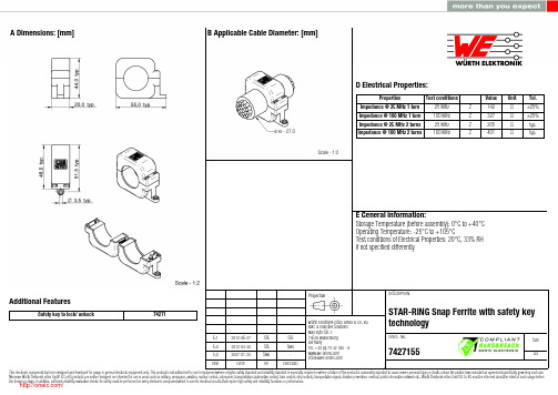
6.1 6.0 5.02012-06-272012-04-302007-01-25SStSStSMuSStSMu-Würth Elektronik eiSos GmbH & Co. KGEMC & Inductive SolutionsMax-Eyth-Str. 174638 WaldenburgGermanyTel. +49 (0) 79 42 945 - 0A Dimensions: [mm]Additional FeaturesSafety key to lock/ unkock74271D2 General Properties:Ferrite core Ferrite core Ferrite core Plastic housing Plastic housing Test cable Test cablePropertiesMaterial Initial permeability Curie temperatureColourFlammability ClassificationApplicable cable Applicable cable lengthµi T CValue 4 W 620620150Grey UL94-V0AWG26120Unit°Cmm Tol.typ.typ.F Typical Impedance Characteristics:I Cautions and Warnings:The following conditions apply to all goods within the product series of WE-STAR RINGof Würth Elektronik eiSos GmbH & Co. KG:General:All recommendations according to the general technical specifications of the data sheet have to be complied with.The disposal and operation of the product within ambient conditions which probably alloy or harm the component surface has to be avoided.The packaging of the product is to encase the needed humidity of the plastic housing. To ensure the humidity level, the products have to be stored in this delivered packaging. If not, the products are losing their humidity. In this case you can re-condition the components according to the internal standard WE1883 to ensure the necessary humidity in the plastic.To ensure the operating mode of the product, the ambient temperature at processing (when the part will be mounted on the cable) has to be in the range of 15 to 25 °C.Before mounting, the part should be stored for one hour in this condition.The responsibility for the applicability of customer specific products and the use in a particular customer design is always within the authority of the customer. All technical specifications for standard products do also apply for customer specific products.Direct mechanical impact to the product and the forcible closing of this shall be prevented as the ferrite material of the ferrite body or the pla-stic housing could flake or in the worst case it could break.Product specific:Follow all instructions mentioned in the datasheet, especially:•The cable diameter must be pointed out, otherwise no warranty will be sustained.•Violation of the technical product specifications such as exceeding the nominal rated current will result in the loss of warranty.1. General Customer ResponsibilitySome goods within the product range of Würth Elektronik eiSos GmbH & Co. KG contain statements regarding general suitability for certain application areas. These statements about suitability are based on our knowledge and experience of typical requirements concerning the are-as, serve as general guidance and cannot be estimated as binding statements about the suitability for a customer application. The responsibi-lity for the applicability and use in a particular customer design is always solely within the authority of the customer. Due to this fact it is up to the customer to evaluate, where appropriate to investigate and decide whether the device with the specific product characteristics described in the product specification is valid and suitable for the respective customer application or not.2. Customer Responsibility related to Specific, in particular Safety-Relevant ApplicationsIt has to be clearly pointed out that the possibility of a malfunction of electronic components or failure before the end of the usual lifetime can-not be completely eliminated in the current state of the art, even if the products are operated within the range of the specifications.In certain customer applications requiring a very high level of safety and especially in customer applications in which the malfunction or failure of an electronic component could endanger human life or health it must be ensured by most advanced technological aid of suitable design of the customer application that no injury or damage is caused to third parties in the event of malfunction or failure of an electronic component.3. Best Care and AttentionAny product-specific notes, warnings and cautions must be strictly observed.4. Customer Support for Product SpecificationsSome products within the product range may contain substances which are subject to restrictions in certain jurisdictions in order to serve spe-cific technical requirements. Necessary information is available on request. In this case the field sales engineer or the internal sales person in charge should be contacted who will be happy to support in this matter.5. Product R&DDue to constant product improvement product specifications may change from time to time. As a standard reporting procedure of the Product Change Notification (PCN) according to the JEDEC-Standard inform about minor and major changes. In case of further queries regarding the PCN, the field sales engineer or the internal sales person in charge should be contacted. The basic responsibility of the customer as per Secti-on 1 and 2 remains unaffected.6. Product Life CycleDue to technical progress and economical evaluation we also reserve the right to discontinue production and delivery of products. As a stan-dard reporting procedure of the Product Termination Notification (PTN) according to the JEDEC-Standard we will inform at an early stage about inevitable product discontinuance. According to this we cannot guarantee that all products within our product range will always be available. Therefore it needs to be verified with the field sales engineer or the internal sales person in charge about the current product availability ex-pectancy before or when the product for application design-in disposal is considered.The approach named above does not apply in the case of individual agreements deviating from the foregoing for customer-specific products.7. Property RightsAll the rights for contractual products produced by Würth Elektronik eiSos GmbH & Co. KG on the basis of ideas, development contracts as well as models or templates that are subject to copyright, patent or commercial protection supplied to the customer will remain with Würth Elektronik eiSos GmbH & Co. KG.8. General Terms and ConditionsUnless otherwise agreed in individual contracts, all orders are subject to the current version of the “General Terms and Conditions of Würth Elektronik eiSos Group”, last version available at .J Important Notes:The following conditions apply to all goods within the product range of Würth Elektronik eiSos GmbH & Co. KG:分销商库存信息: WURTH-ELECTRONICS 7427155。
3.2 x 2.8 mm PLCC2 SMD LED 商品说明书

Part Number Emitting Color Emitting MaterialLens-colorWavelength CIE127-2007*nm λPViewing Angle 2θ 1/2Luminous Intensity CIE127-2007* (I F =20mA) mcd *Luminous intensity value and wavelength are in accordance with CIE127-2007 standards.A Relative Humidity between 40% and 60% is recommended inESD-protected work areas to reduce static build up during assembly process (Reference JEDEC/JESD625-A and JEDEC/J-STD-033)Features● Ideal for indication light on hand held products ● Long life and robust package ● Standard Package: 2000pcs/ Reel ● MSL (Moisture Sensitivity Level): 3 ● Halogen-free ● RoHS compliantATTENTIONOBSERVE PRECAUTIONSFOR HANDLING ELECTROSTATIC DISCHARGE SENSITIVE DEVICESLED is recommended for reflow soldering and soldering profile is shown below.Forward Current Derating CurveThe device has a single mounting surface. The device must be mounted according to the specifications.Reel Dimension (Units : mm)Recommended Soldering Pattern (Units : mm; Tolerance: ± 0.1)Tape Specification (Units : mm)Remarks:If special sorting is required (e.g. binning based on forward voltage, Luminous intensity / luminous flux, or wavelength), the typical accuracy of the sorting process is as follows: 1. Wavelength: +/-1nm2. Luminous intensity / luminous flux: +/-15%3. Forward Voltage: +/-0.1VNote: Accuracy may depend on the sorting parameters.TERMS OF USE1. Data presented in this document reflect statistical figures and should be treated as technical reference only.2. Contents within this document are subject to improvement and enhancement changes without notice.3. The product(s) in this document are designed to be operated within the electrical and environmental specifications indicated on the datasheet. User accepts full risk and responsibility when operating the product(s) beyond their intended specifications.4. The product(s) described in this document are intended for electronic applications in which a person’s life is not reliant upon the LED. Please consult with a SunLED representative for special applications where the LED may have a direct impact on a person’s life.5. The contents within this document may not be altered without prior consent by SunLED.6. Additional technical notes are available at https:///TechnicalNotes.aspPACKING & LABEL SPECIFICATIONS。
英飞凌 FP10R12W1T7 EasyPIM 模块 数据表

Preliminary datasheetEasyPIM ™ 模块 采用第七代沟槽栅/场终止IGBT7和第七代发射极控制二极管带有温度检测NTC 特性•电气特性-沟槽栅IGBT7-过载操作达175°C -低 V CEsat •机械特性-焊接技术-紧凑型设计-高功率密度-低热阻的三氧化二铝 Al 2O 3 衬底-2.5 kV 交流 1分钟 绝缘可选应用•空调•辅助逆变器•电机传动产品认证•根据 IEC 60747、60749 和 60068 标准的相关测试,符合工业应用的要求。
描述FP10R12W1T7EasyPIM ™ 模块内容描述 . . . . . . . . . . . . . . . . . . . . . . . . . . . . . . . . . . . . . . . . . . . . . . . . . . . . . . . . . . . . . . . . . . . . . . . . . . . . . . . . . . . . . . . . .1特性 . . . . . . . . . . . . . . . . . . . . . . . . . . . . . . . . . . . . . . . . . . . . . . . . . . . . . . . . . . . . . . . . . . . . . . . . . . . . . . . . . . . . . . . . .1可选应用 . . . . . . . . . . . . . . . . . . . . . . . . . . . . . . . . . . . . . . . . . . . . . . . . . . . . . . . . . . . . . . . . . . . . . . . . . . . . . . . . . . . .1产品认证 . . . . . . . . . . . . . . . . . . . . . . . . . . . . . . . . . . . . . . . . . . . . . . . . . . . . . . . . . . . . . . . . . . . . . . . . . . . . . . . . . . . .1内容 . . . . . . . . . . . . . . . . . . . . . . . . . . . . . . . . . . . . . . . . . . . . . . . . . . . . . . . . . . . . . . . . . . . . . . . . . . . . . . . . . . . . . . . . .2 1封装 . . . . . . . . . . . . . . . . . . . . . . . . . . . . . . . . . . . . . . . . . . . . . . . . . . . . . . . . . . . . . . . . . . . . . . . . . . . . . . . . . . . . . . . . .3 2IGBT, 逆变器 . . . . . . . . . . . . . . . . . . . . . . . . . . . . . . . . . . . . . . . . . . . . . . . . . . . . . . . . . . . . . . . . . . . . . . . . . . . . . . . . .3 3二极管,逆变器 . . . . . . . . . . . . . . . . . . . . . . . . . . . . . . . . . . . . . . . . . . . . . . . . . . . . . . . . . . . . . . . . . . . . . . . . . . . . . . .5 4二极管,整流器 . . . . . . . . . . . . . . . . . . . . . . . . . . . . . . . . . . . . . . . . . . . . . . . . . . . . . . . . . . . . . . . . . . . . . . . . . . . . . . .6 5IGBT, 制动-斩波器 . . . . . . . . . . . . . . . . . . . . . . . . . . . . . . . . . . . . . . . . . . . . . . . . . . . . . . . . . . . . . . . . . . . . . . . . . . . .7 6二极管,制动-斩波器 . . . . . . . . . . . . . . . . . . . . . . . . . . . . . . . . . . . . . . . . . . . . . . . . . . . . . . . . . . . . . . . . . . . . . . . . .8 7负温度系数热敏电阻 . . . . . . . . . . . . . . . . . . . . . . . . . . . . . . . . . . . . . . . . . . . . . . . . . . . . . . . . . . . . . . . . . . . . . . . . .9 8特征参数图表 . . . . . . . . . . . . . . . . . . . . . . . . . . . . . . . . . . . . . . . . . . . . . . . . . . . . . . . . . . . . . . . . . . . . . . . . . . . . . . .10 9电路拓扑图 . . . . . . . . . . . . . . . . . . . . . . . . . . . . . . . . . . . . . . . . . . . . . . . . . . . . . . . . . . . . . . . . . . . . . . . . . . . . . . . . .16 10封装尺寸 . . . . . . . . . . . . . . . . . . . . . . . . . . . . . . . . . . . . . . . . . . . . . . . . . . . . . . . . . . . . . . . . . . . . . . . . . . . . . . . . . . .17 11模块标签代码 . . . . . . . . . . . . . . . . . . . . . . . . . . . . . . . . . . . . . . . . . . . . . . . . . . . . . . . . . . . . . . . . . . . . . . . . . . . . . . .18免责声明 . . . . . . . . . . . . . . . . . . . . . . . . . . . . . . . . . . . . . . . . . . . . . . . . . . . . . . . . . . . . . . . . . . . . . . . . . . . . . . . . . . .191封装表 1绝缘参数特征参数代号标注或测试条件数值单位绝缘测试电压V ISOL RMS, f = 50 Hz, t = 1 min 2.5kV 内部绝缘基本绝缘 (class 1, IEC 61140)Al2O3爬电距离d Creep端子至散热器11.5mm 爬电距离d Creep端子至端子 6.3mm 电气间隙d Clear端子至散热器10.0mm 电气间隙d Clear端子至端子 5.0mm 相对电痕指数CTI > 200相对温度指数 (电)RTI住房140°C 表 2特征值特征参数代号标注或测试条件数值单位最小值典型值最大值杂散电感,模块L sCE30nH 模块引线电阻,端子-芯片R AA'+CC'T H=25°C, 每个开关6mΩ模块引线电阻,端子-芯片R CC'+EE'T H=25°C, 每个开关8mΩ储存温度T stg-40125°C Mounting force per clamp F2050N 重量G24g注:The current under continuous operation is limited to 30A rms per connector pin.2IGBT, 逆变器表 3最大标定值特征参数代号标注或测试条件数值单位集电极-发射极电压V CES T vj = 25 °C1200V 连续集电极直流电流I CDC T vj max = 175 °C T H = 100 °C10A 集电极重复峰值电流I CRM t P = 1 ms20A 栅极-发射极峰值电压V GES±20V表 4特征值特征参数代号标注或测试条件数值单位最小值典型值最大值集电极-发射极饱和电压V CE sat I C = 10 A, V GE = 15 V T vj = 25 °C 1.60TBD VT vj = 125 °C 1.74T vj = 175 °C 1.82栅极阈值电压V GEth I C = 0.22 mA, V CE = V GE, T vj = 25 °C 5.15 5.80 6.45V 栅极电荷Q G V GE = ±15 V, V CE = 600 V0.157µC 内部栅极电阻R Gint T vj = 25 °C0Ω输入电容C ies f = 100 kHz, T vj = 25 °C, V CE = 25 V, V GE = 0 V 1.89nF 反向传输电容C res f = 100 kHz, T vj = 25 °C, V CE = 25 V, V GE = 0 V0.0066nF 集电极-发射极截止电流I CES V CE = 1200 V, V GE = 0 V T vj = 25 °C0.0045mA 栅极-发射极漏电流I GES V CE = 0 V, V GE = 20 V, T vj = 25 °C100nA开通延迟时间(感性负载)t don I C = 10 A, V CE = 600 V,V GE = ±15 V, R Gon = 8.2 ΩT vj = 25 °C0.023µs T vj = 125 °C0.025T vj = 175 °C0.026上升时间(感性负载)t r I C = 10 A, V CE = 600 V,V GE = ±15 V, R Gon = 8.2 ΩT vj = 25 °C0.014µs T vj = 125 °C0.017T vj = 175 °C0.019关断延迟时间(感性负载)t doff I C = 10 A, V CE = 600 V,V GE = ±15 V, R Goff = 8.2 ΩT vj = 25 °C0.124µs T vj = 125 °C0.157T vj = 175 °C0.176下降时间(感性负载)t f I C = 10 A, V CE = 600 V,V GE = ±15 V, R Goff = 8.2 ΩT vj = 25 °C0.227µs T vj = 125 °C0.347T vj = 175 °C0.422开通损耗能量 (每脉冲)E on I C = 10 A, V CE = 600 V,Lσ = 35 nH, V GE = ±15 V,R Gon = 8.2 Ω, di/dt = 550A/µs (T vj = 175 °C)T vj = 25 °C0.73mJ T vj = 125 °C0.94T vj = 175 °C 1.13关断损耗能量 (每脉冲)E off I C = 10 A, V CE = 600 V,Lσ = 35 nH, V GE = ±15 V,R Goff = 8.2 Ω, dv/dt =2700 V/µs (T vj = 175 °C)T vj = 25 °C0.623mJ T vj = 125 °C0.97T vj = 175 °C 1.17表 4特征值 (continued)特征参数代号标注或测试条件数值单位最小值典型值最大值短路数据I SC V GE≤ 15 V, V CC = 800 V,V CEmax=V CES-L sCE*di/dt t P≤ 8 µs,T vj = 150 °C32At P≤ 7 µs,T vj = 175 °C30结-散热器热阻R thJH每个 IGBT 2.05K/W 允许开关的温度范围T vj op-40175°C注:T vj op > 150°C is allowed for operation at overload conditions. For detailed specifications, please refer to AN 2018-14.3二极管,逆变器表 5最大标定值特征参数代号标注或测试条件数值单位反向重复峰值电压V RRM T vj = 25 °C1200V 连续正向直流电流I F10A 正向重复峰值电流I FRM t P = 1 ms20A I2t-值I2t V R = 0 V, t P = 10 ms T vj = 125 °C27.5A²sT vj = 175 °C24表 6特征值特征参数代号标注或测试条件数值单位最小值典型值最大值正向电压V F I F = 10 A, V GE = 0 V T vj = 25 °C 1.72TBD VT vj = 125 °C 1.59T vj = 175 °C 1.52反向恢复峰值电流I RM I F = 10 A, V R = 600 V,V GE = -15 V, -di F/dt = 550A/µs (T vj = 175 °C)T vj = 25 °C10.5A T vj = 125 °C15.3T vj = 175 °C17.5恢复电荷Q r I F = 10 A, V R = 600 V,V GE = -15 V, -di F/dt = 550A/µs (T vj = 175 °C)T vj = 25 °C0.97µC T vj = 125 °C 1.7T vj = 175 °C 2.2表 6特征值 (continued)特征参数代号标注或测试条件数值单位最小值典型值最大值反向恢复损耗(每脉冲)E rec I F = 10 A, V R = 600 V,V GE = -15 V, -di F/dt = 550A/µs (T vj = 175 °C)T vj = 25 °C0.24mJ T vj = 125 °C0.51T vj = 175 °C0.72结-散热器热阻R thJH每个二极管 2.45K/W 允许开关的温度范围T vj op-40175°C注:T vj op > 150°C is allowed for operation at overload conditions. For detailed specifications, please refer to AN 2018-14.4二极管,整流器表 7最大标定值特征参数代号标注或测试条件数值单位反向重复峰值电压V RRM T vj = 25 °C1600V 最大正向均方根电流(每芯片)I FRMSM T H = 100 °C25A 最大整流器输出均方根电流I RMSM T H = 100 °C25A 正向浪涌电流I FSM t P = 10 ms T vj = 25 °C300AT vj = 150 °C245I2t-值I2t t P = 10 ms T vj = 25 °C450A²sT vj = 150 °C300表 8特征值特征参数代号标注或测试条件数值单位最小值典型值最大值正向电压V F I F = 10 A T vj = 150 °C0.80V 反向电流I r T vj = 150 °C, V R = 1600 V1mA 结-散热器热阻R thJH每个二极管 1.54K/W 允许开关的温度范围T vj, op-40150°C5IGBT, 制动-斩波器表 9最大标定值特征参数代号标注或测试条件数值单位集电极-发射极电压V CES T vj = 25 °C1200V 连续集电极直流电流I CDC T vj max = 175 °C T H = 100 °C10A 集电极重复峰值电流I CRM t P = 1 ms20A 栅极-发射极峰值电压V GES±20V表 10特征值特征参数代号标注或测试条件数值单位最小值典型值最大值集电极-发射极饱和电压V CE sat I C = 10 A, V GE = 15 V T vj = 25 °C 1.60TBD VT vj = 125 °C 1.74T vj = 175 °C 1.82栅极阈值电压V GEth I C = 0.22 mA, V CE = V GE, T vj = 25 °C 5.15 5.80 6.45V 栅极电荷Q G V GE = ±15 V, V CE = 600 V0.157µC 内部栅极电阻R Gint T vj = 25 °C0Ω输入电容C ies f = 100 kHz, T vj = 25 °C, V CE = 25 V, V GE = 0 V 1.89nF 反向传输电容C res f = 100 kHz, T vj = 25 °C, V CE = 25 V, V GE = 0 V0.0066nF 集电极-发射极截止电流I CES V CE = 1200 V, V GE = 0 V T vj = 25 °C0.0045mA 栅极-发射极漏电流I GES V CE = 0 V, V GE = 20 V, T vj = 25 °C100nA开通延迟时间(感性负载)t don I C = 10 A, V CE = 600 V,V GE = ±15 V, R Gon = 8.2 ΩT vj = 25 °C0.023µs T vj = 125 °C0.025T vj = 175 °C0.026上升时间(感性负载)t r I C = 10 A, V CE = 600 V,V GE = ±15 V, R Gon = 8.2 ΩT vj = 25 °C0.014µs T vj = 125 °C0.017T vj = 175 °C0.019关断延迟时间(感性负载)t doff I C = 10 A, V CE = 600 V,V GE = ±15 V, R Goff = 8.2 ΩT vj = 25 °C0.124µs T vj = 125 °C0.157T vj = 175 °C0.176下降时间(感性负载)t f I C = 10 A, V CE = 600 V,V GE = ±15 V, R Goff = 8.2 ΩT vj = 25 °C0.227µs T vj = 125 °C0.347T vj = 175 °C0.422表 10特征值 (continued)特征参数代号标注或测试条件数值单位最小值典型值最大值开通损耗能量 (每脉冲)E on I C = 10 A, V CE = 600 V,Lσ = 35 nH, V GE = ±15 V,R Gon = 8.2 Ω, di/dt = 550A/µs (T vj = 175 °C)T vj = 25 °C0.73mJ T vj = 125 °C0.94T vj = 175 °C 1.13关断损耗能量 (每脉冲)E off I C = 10 A, V CE = 600 V,Lσ = 35 nH, V GE = ±15 V,R Goff = 8.2 Ω, dv/dt =2700 V/µs (T vj = 175 °C)T vj = 25 °C0.623mJ T vj = 125 °C0.97T vj = 175 °C 1.17短路数据I SC V GE≤ 15 V, V CC = 800 V,V CEmax=V CES-L sCE*di/dt t P≤ 8 µs,T vj = 150 °C32At P≤ 7 µs,T vj = 175 °C30结-散热器热阻R thJH每个 IGBT 2.05K/W 允许开关的温度范围T vj op-40175°C注:T vj op > 150°C is allowed for operation at overload conditions. For detailed specifications, please refer to AN 2018-14.6二极管,制动-斩波器表 11最大标定值特征参数代号标注或测试条件数值单位反向重复峰值电压V RRM T vj = 25 °C1200V 连续正向直流电流I F10A 正向重复峰值电流I FRM t P = 1 ms20A I2t-值I2t V R = 0 V, t P = 10 ms T vj = 125 °C27.5A²sT vj = 175 °C24表 12特征值特征参数代号标注或测试条件数值单位最小值典型值最大值正向电压V F I F = 10 A, V GE = 0 V T vj = 25 °C 1.72TBD VT vj = 125 °C 1.59T vj = 175 °C 1.52表 12特征值 (continued)特征参数代号标注或测试条件数值单位最小值典型值最大值反向恢复峰值电流I RM I F = 10 A, V R = 600 V,-di F/dt = 550 A/µs(T vj = 175 °C)T vj = 25 °C10.5A T vj = 125 °C15.3T vj = 175 °C17.5恢复电荷Q r I F = 10 A, V R = 600 V,-di F/dt = 550 A/µs(T vj = 175 °C)T vj = 25 °C0.97µC T vj = 125 °C 1.7T vj = 175 °C 2.2反向恢复损耗(每脉冲)E rec I F = 10 A, V R = 600 V,-di F/dt = 550 A/µs(T vj = 175 °C)T vj = 25 °C0.24mJ T vj = 125 °C0.51T vj = 175 °C0.72结-散热器热阻R thJH每个二极管 2.45K/W 允许开关的温度范围T vj op-40175°C注:T vj op > 150°C is allowed for operation at overload conditions. For detailed specifications, please refer to AN 2018-14.7负温度系数热敏电阻表 13特征值特征参数代号标注或测试条件数值单位最小值典型值最大值额定电阻值R25T NTC = 25 °C5kΩR100偏差ΔR/R T NTC = 100 °C, R100 = 493 Ω-55%耗散功率P25T NTC = 25 °C20mW B-值B25/50R2 = R25 exp[B25/50(1/T2-1/(298,15 K))]3375K B-值B25/80R2 = R25 exp[B25/80(1/T2-1/(298,15 K))]3411K B-值B25/100R2 = R25 exp[B25/100(1/T2-1/(298,15 K))]3433K 注:根据应用手册标定7 负温度系数热敏电阻9电路拓扑图图 210封装尺寸图 311 模块标签代码11模块标签代码图 4商标所有参照产品或服务名称和商标均为其各自所有者的财产。
wika远传密度继电器资料
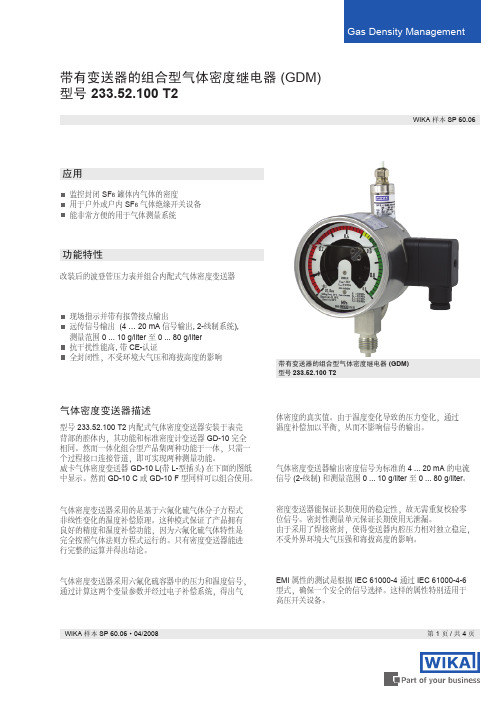
压力校验PE 参照订货说明
容许使用温度 环境温度:-20 ... +60°C (气态) 储存温度:-50 ... +60°C
报警接点 / 开关功率 最多3个磁助式电接点,接通或断开,镀绝缘层, 开关点不可调节性和安全性。 开关功率:20 W / 20 VA, 最大 1 A 接点材料:80% Ag / 20% Ni, 10µm 镀金 电接点具有完好的长期稳定性
表玻璃 多层安全表玻璃
镶嵌环 卡口环,CrNi-不锈钢, 并采用3个焊接点固定
防护等级标准 IP 65 EN 60 529 / IEC 529
重量 约 1.2 kg
优化选项
3 个磁助式电接点,无绝缘镀层 开关点可调 丙烯酯化仪表玻璃 SF6 混合物补偿 法兰式压力接口连接 压力接口在3点、6点或12点钟位置 背部连接 可插入或取下的电缆接线盒 客户定制特殊版本
绝压 G ½ B 阳螺纹 (其它连接请询问)
不锈钢 不锈钢 硅油
60 8.87
29 35
80 11.33
67 80
辅助电源 U B 信号输出和 最大负载 R A
精度等级
DC V 量程的 %
10 < UB ≤ 30
4 ... 20 mA, 2-线制, RA≤ (UB-10 V) / 0.02 A RA (欧姆) UB (伏特)
WIKA 样本 SP 60.06·04/2008
第1页/共4页
气体密度继电器描述
表圆直径 100 mm,变送器安装于特殊加长段表壳内
精度等级(针对测量范围而言) 环境温度在 +20 °C 时精度等级 ± 1 %