LanderCluster 6 产品介绍
Spartan-6 系列概述

DS160 (v1.6) 2010 年 11 月 5 日 推进产品规范发展
概述
Spartan®-6 系列不仅拥有业界领先的系统集成能力,同时还能实现适用于大批量应用的最低总成本。该系列由 13 个成员组成,可提供 的密度从 3,840 个逻辑单元到 147,443 个逻辑单元不等。与上一代 Spartan 系列相比,该系列功耗仅为其 50%,且速度更快、连接功 能更丰富全面。Spartan-6 系列采用成熟的 45nm 低功耗铜制程技术制造,实现了性价比与功耗的完美平衡,能够提供全新且更高效的 双寄存器 6 输入查找表 (LUT) 逻辑和一系列丰富的内置系统级模块,其中包括 18Kb (2 x 9Kb) Block RAM、第二代 DSP48A1 Slice、 SDRAM 存储器控制器、增强型混合模式时钟管理模块、SelectIO™ 技术、功率优化的高速串行收发器模块、PCI Express® 兼容端点模 块、高级系统级电源管理模式、自动检测配置选项,以及通过 AES 和 Device DNA 保护功能实现的增强型 IP 安全性。这些优异特性以 前所未有的易用性为定制 ASIC 产品提供了低成本的可编程替代方案。Spartan-6 FPGA 可为大批量逻辑设计、以消费类为导向的 DSP 设计以及成本敏感型嵌入式应用提供最佳解决方案。Spartan-6 FPGA 奠定了坚实的可编程芯片基础,非常适用于可提供集成软硬件组件 的目标设计平台,以使设计人员在开发工作启动之初即可将精力集中到创新工作上。
Spartan-6 FPGA 特性总结
• Spartan-6 系列: • Spartan-6 LX FPGA:逻辑优化 • Spartan-6 LXT FPGA:高速串行连接 • 专用于低成本设计 • 多重高效率集成模块 • 优化 I/O 标准选择 • 交错式焊盘 • 大批量塑料焊线封装 • 极低的静态与动态功耗 • 45nm 工艺,专为低成本与低功耗而精心优化 • 零功耗休眠关闭模式 • 待机模式可以保持状态和配置,具有多引脚唤醒、控制增 强功能 • 功耗更低的 1.0V 内核电压(LX FPGA,仅 -1L) • 高性能 1.2V 内核电压(LX 和 LXT FPGA,-2、-3、-3N 和 -4 速度级别) • 多电压、多标准 SelectIO™ 接口 bank • 每对差分 I/O 的数据传输速率均高达 1,080Mb/s • 可选输出驱动器,每个引脚的电流最高达 24mA • 兼容 3.3V ~ 1.2V I/O 标准和协议 • 低成本 HSTL 与 SSTL 存储器接口 • 符合热插拔规范 • 可调 I/O 转换速率,提高信号完整性 • LTX FPGA 内置高速 GTP 串行收发器 • 最高速度达 3.2Gb/s • 支持高速接口,包括:串行 ATA、Aurora、1G 以太网、PCI Express、OBSAI、CPRI、EPON、GPON、DisplayPort 以 及 XAUI 等 • 支持 PCI Express 设计方案的集成端点模块(LXT 器件) • 支持兼容 33MHz、32 位或 64 位规范的低成本 PCI® 技术 • 高效率 DSP48A1 Slice • 高性能算术与信号处理 • 快速 18 x 18 乘法器和 48 位累加器 • 流水线与级联功能 • 用于协助滤波器应用的预加法器 • 集成存储器控制器模块 • DDR、DDR2、DDR3 和 LPDDR 支持 • 数据速率高达 800Mb/s(12.6Gb/s 的峰值带宽) • 多端口总线结构,带独立 FIFO,减少了设计时序问题 • 丰富的逻辑资源和更大的逻辑容量 • 支持移位寄存器或分布式 RAM • 高效的 6 输入查找表可以提升性能和将功耗降至最低 • 针对以流水线应用而设计的 LUT,具有双触发器 • 具有各种粒度的 Block RAM • 快速 Block RAM,具有字节写入功能 • 18Kb RAM 块,可以选择性地将其编程为 2 个独立的 9Kb Block RAM • 时钟管理模块 (CMT),可以提升性能 • 低噪声,高灵活度的时钟控制 • 数字时钟管理器 (DCM),可消除时钟歪斜和占空比失真 • 锁相环 (PLL),可实现低抖动时钟控制 • 频率综合实现倍频、分频和调相 • 16 个低歪斜全局时钟网络 • 简化配置,实现低成本 • 双引脚自动检测配置 • 广泛支持第三方 SPI(高达 4 位宽度)和 NOR 闪存 • 特性丰富的、带有 JTAG 的赛灵思平台闪存 • 多重启动 (MultiBoot) 支持,可以利用多个比特流和看门 狗保护功能进行远程升级 • 更高安全性,可为设计提供强大保护 • 唯一的设备 DNA 标识符,用于设计验证 • 在较大型器件中可进行 AES 比特流加密 • 采用低成本的增强型 MicroBlazeTM 软处理器实现更快速的嵌 入式处理 • 业界领先的 IP 和参考设计
ROSE产品的介绍

总述
产品特点介绍 同类产品比较 典型解决方案
Rose产品介绍 产品介绍
● RoseHA 利用共享磁盘提供双机的高可用保证应用不间断运行纯软件 解决方案。 解决方案。 ● RoseMirrorHA 不采用共享磁盘,基于镜像技术保证应用不间断运行而提供 不采用共享磁盘, 的双机高可用的纯软件解决方案。 的双机高可用的纯软件解决方案。 ● RoseReplicator 提供实时的数据复制,保证主备主机数据完全一致,使数据 提供实时的数据复制,保证主备主机数据完全一致, 灾难恢复。 灾难恢复。 ● PowerReplicator 整合了利用共享磁盘和镜像数据方式提供高可用的解决方案, 整合了利用共享磁盘和镜像数据方式提供高可用的解决方案, 同时支持多节点实时复制功能的软件产品。 同时支持多节点实时复制功能的软件产品。 ● RoseDataBack 支持持续数据保护功能,能够恢复任意时间点的数据。 支持持续数据保护功能,能够恢复任意时间点的数据。
Байду номын сангаас复制文件权限 通过多个客户端对服 务器进行管理 UNC路径(目标) 路径(目标) 路径 支持语言
RoseReplicator集成了数据容灾和高可用功能于一身的软件,其功能 集成了数据容灾和高可用功能于一身的软件, 集成了数据容灾和高可用功能于一身的软件 很强大,能够满足存储业许多客户对高可用,容灾、 很强大,能够满足存储业许多客户对高可用,容灾、备份等解决方案 的需求。其技术含量较高,同时价格相对比较低。 的需求。其技术含量较高,同时价格相对比较低。
Windows\Linux \HP- UX\ Solaris 支持 依赖VVR 依赖VVR 块级镜像 Veritas VVR 英文 高
LandMark Spatial Solutions产品介绍说明书

ArcGIS is the industry standard GIS program, and the current version allows you to stream in high-res photos, topos, road layers, and hundreds of other layers fromESRI’s warehouse of GIS info on ArcGIS Online. You can2. Create a Cruise Grid In the office or field, you can specifythe grid spacing and orientation and even begin the grid 1/2 thedistance over and up from a known corner.3. Navigate to a Plot—to go to and use GPS to navigate there. When youget within a specified distance from plot center, Solo4. Enter Plot Data—If you answer “YES”, a link will be establishedbetween SoloField and TCruise, the plot ID and Lat./Long. will besent to TCruise, and you will be automatically “switched” to TCruise.You can then enter Plot Info and then go to the data entry screen.5. Enter Tree Datatrees and save the plot in TCruise. You can entertrees in a tally card or spreadsheet format, both ofwhich have your species, products, and merchandizingWhen you finish the first plot, you simply go back to Solo Forest, selectthe next plot and keep going. All cruised plots are marked in Solo Forest as “Visited”.printable, reports.LandMark Spatial Solutions is proud to announce our very own EZ-is the first forestry specific handheld ever developed.2016 LMSS Mapping Grade GPS HandheldsIII instrument ideal for measuring fixed radius plots. By placing curately determine if the object is “in” the plot. By allowing youto work the plot from the outside in, your production per plot iswell. By selecting one of the built in BAF’s you are able to be atthe tree and determine its minimum diameter to be included inthe point. This function allows you the ability to Prism cruise onundergrowth - perfect timing for the Vertex! When sighting ismethod is superior in speed and simplicity. The NEW VL5 unit measurements are shown in the display, you never haveheight instantly by using the built-in three-shot routine.going to multiple destinations by multiple haulers Harvest operators enter load data on their iOS orinto remote operations can shorten reconciliation2.Phantom 4 quad copter is also a very effectivetool for mapping log deck and chip piles to de-termine inventory volumes. The Issue here isthat the data must be processed through somemapping software of some sort to determine 3Dvolumes. The software that we believe is mosteffective for this is the Pix4D software which wesell and use. Call us for more info on how thisworks.cessed in several different ways,but we sell and recommend both。
群集技术:三款主流服务器集群软件
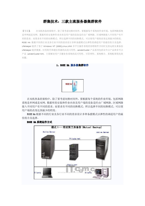
群集技术:三款主流服务器集群软件【导读】:在双机热备的架构中,除了要考虑切换时间外,要根据每个系统的作业环境,包括网路系统是单网或是双网,数据库的安装和作业内容及用户端的设备是经由广域网路、区域网路接入不同用户有不同的需求,而要求有不同的切换模式,所以选择不同的切换模式,可以使用户端的改变达到最少的程度。
ROSE HA根据不同的行业及各行业不同的需求设计多种备援模式以弹性的调适用户的最佳组合及选择。
LifeKeeper提供了基于Windows NT (2000),Linux,UNIX多平台操作系统的容错软件并同时支持远程灾难备份LifeKeeper提供数据、应用程序和通信资源的高度可用性。
LanderCluster产品系列包括双节点产品和多节点产品LanderCluster-MN。
主要解决用户关键业务系统的高可用性、可管理性、系统整合、系统配置优化的问题。
1、ROSE HA 服务器集群软件在双机热备的架构中,除了要考虑切换时间外,要根据每个系统的作业环境,包括网路系统是单网或是双网,数据库的安装和作业内容及用户端的设备是经由广域网路、区域网路接入不同用户有不同的需求,而要求有不同的切换模式,所以选择不同的切换模式,可以使用户端的改变达到最少的程度。
ROSE HA根据不同的行业及各行业不同的需求设计多种备援模式以弹性的调适用户的最佳组合及选择。
ROSE HA系统运作方式在正常的运作情形之下,主机之间透过冗余侦测线路互相侦测,当任一主机有错误产生时,ROSE HA提供严谨的判断与分析,确认主机出错之后,才完全启动备援接管动作。
※支持各种操作系统平台※支持众多的UNIX平台(如:IBM、DEC、HP、NCR、SUN、SGI、NEC、SIEMENS等)※支持众多的PC平台的Unix系统(如:SCO/Unix、Solraris X86等)※支持各种数据库:MS-SQL、Oracle 、Informix、Sysbase、Excheng 、Lotus/Nose、DB2等接管动作包括※文件系统( File System)※数据库( Database)※网络地址( IP Address)※应用程序(AP)※系统环境(OS)※容错备援运作过程自动侦测(Auto-Detect)阶段,由主机上的软件通过冗余侦测线,经由复杂的监听程序。
双机热备产品比较

双机热备产品比较目前双机市场上的产品较多,也比较混乱,对用户来说选择一个比较好的产品十分必要,不但要考虑到产品的功能、还要考虑到产品的后续服务、厂家的支持能力等多方面问题。
下面对市场上的产品进行简单的分类:?Veritas的VCS、Microsoft的MSCS、Legato 的LAAM等产品属于高端产品,价格昂贵(一个双机基本上要多出5万投资),而且系统的维护、实施相当复杂,虽然有不少用户在使用,但真正能够的到厂商支持的,并不多,都处于自行维护状态。
总体上讲,性价比非常的差。
?而NCR的LifeKeeper、Legato 的Co-standby Server市场定位上属于第二集团,他们价格定位在2万左右,但由于是国外产品,同样存在技术支持的问题,而且,目前这两个产品盗版很多,用户常常会无端受害。
对于这样的产品,其定位还是偏高了,因为技术上,这两个产品并无太多可圈可点之处。
?而其他产品就是以Rose为主的台湾品牌,他们包括RoseHA、Dataware等,还有很多不知出处的产品,比如SuperHA、Pluswell、Goldenlife、LHA等,这里面就更加混乱,因为真正能够支持到位的产品很少,因为这些产品除了RoseHA以外,都是以硬件销售为主、或者是OEM的产品。
这些产品有的功能简单,没有开发团队,有的为了推销磁盘阵列而OEM一个,更有的纯粹盗版,用户的合法权利没法保障,其使用双机的目的就是为系统更加可靠,所以在选择产品要注意。
?LanderCluster是完全自主产权的国内产品,由上海联鼎软件技术有限公司研发,在该产品研发推广上,公司投入了超过800万人民币和大量人力,产品从低端到支持高端多节点、小型机平台环境。
是一个产品线非常完整的系列,曾经实现多个国内第一:第一个在SCO OpenServer5上实现银行中间业务系统整合(5节点集群)、第一个在企业ERP关键业务环境/纯光纤环境下实现UnixWare多节点集群、第一个集中管理环境下并支持中文环境的Windows集群。
LanderVault容灾统一管理平台

什么是容灾集中管理平台LanderVault 核心业务容灾集中管理平台定位于保障企业级核心应用与数据安全,通过最大程度缩短企业核心业务停顿及全面保护企业重要数据安全,达到减小企业重要信息资产损失的目的。
一体化容灾解决方案LanderVault是一款集合高可用集群、数据复制、备份和系统容灾等功能于一体的数据安全产品集,定位于保障企业级核心应用与数据安全,通过最大程度缩短企业核心业务停顿及全面保护企业重要数据安全,达到减小企业重要信息资产损失的目的,是先进的一体化智能安全管理平台综合性解决方案。
核心业务容灾集中管理平台LanderVault管理平台基于Java虚拟机的跨平台管理端,将用户的关键业务按照业务逻辑分组管理,在一个控制台上能方便地部署数据安全产品,随时监控主机系统信息、网络信息、存储信息、进程信息和服务等信息,可以对数据安全产品进行管理及控制。
LanderVault容灾管理平台主要实现如下功能:集中管理远程管理跨平台管理管理和监控服务器管理和配置集群软件管理和配置复制软件管理和配置备份软件管理和配置容灾软件管理事务日志管理系统告警(邮件,声音,短消息)管理许可证数据安全系列产品包括如下模块:LanderVault:集中管理平台LanderCluster:高可用集群模块LanderReplicator:网格化数据复制模块LanderBackup:数据备份模块LanderDisaster:数据容灾模块每个模块都可以作为独立产品销售。
高可用集群模块:LanderClusterLanderVault体系中全新的高可用集群模块负责全面监控及保障用户核心应用,应用创造性的“故障分级”概念和独特的“故障预警”功能,在核心系统处于危险的状态下及时发出“警告”,并在必要的情况下自动执行精确而迅速的故障隔离及应用转移,保障用户核心应用7×24小时持续可靠运作,可支持多达256个节点的应用。
数据复制模块:LanderReplicatorLanderVault体系中的数据复制模块为您提供基于网格化的数据同步复制及数据可实时回放的CDP功能,无需购入任何其它设备就可以在现有系统中使用,从而为您节省成本。
lord corporation ll-6006 耐用性衰退模式的连接可伸缩产品和维护指南 说明书
Lord Corporation LL-6006 The Degradation Modes of Bonded, Elastomeric ProductsAnd Guidelines for Maintaining ThemBy E. L. Brubaker and M. W. Downing, Lord Mechanical ProductsTHE DEGRADATION MODES OF BONDED, ELASTOMERIC PRODUCTSAnd Guidelines For Maintaining ThemElastomeric bearings and mountings are widely used in helicopters and fixed wing aircraft due to their maintenance-free long life, vibration-reducing characteristics and their gradual fail-safe modes of degradation. Because these products usually have on-condition removal criteria, maintenance personnel need to understand the cause and effects of elastomer degradation in order to increase aircraft reliability and readiness, and to reduce direct operating costs.The term bearing is used for elastomeric parts whose primary function is cyclical motions (i.e. pitch link bearing), and the term mounting is used where the primary function is load support (i.e. engine mount). Helicopter applications usually require bearings and most fixed wing aircraft applications require mountings. You will see both terms used in this article as appropriate to each degradation mode.Fatigue life or MTBF (mean-time-between-failure) of elastomeric bearings is calculated analytically early in the aircraft design stage, based on the load and motion spectrum of the "average" bearing and the size envelope allotted. Actual service life, though, is greatly determined by individual usage and environment. This has led to adopting visual on-condition replacement of elastomeric bearings. Visual criteria are established by comparing visual appearance to performance during controlled fatigue testing.In addition, visual on-condition replacement is used to overcome the difficulties of field testing to determine serviceability. Lord has established and published a maintenance manual to serve this purpose. Actual testing of an elastomeric bearing requires specialized machines, fixtures and technicians which are beyond the scope of most field service operations. In addition to the visual criteria established during fatigue testing, inspection of return-from-service parts reveals that three primary forms of degradation determine the actual service life of elastomeric bearings. Typically, combinations of fatigue, overload, and "oil" or fluid contamination are seen. Environmental conditions may also speed up the aging processes inherent to most elastomers. The article provides a description of each of these failure modes and concludes with some guidelines for inspection.FatiguePhoto 1Acceptable Fatigue on Helicopter Nodal Beam(Bell 214 Type)Photo 2Unacceptable Fatigue and Fluid Contamination onTurboprop Engine Mounting(deHavilland Dash 8)As an elastomeric bearing cycles through its motions, small surface cracks will eventually form in the highest strained regions of the bearing. These cracks will grow deeper into the elastomer, allowing the crack faces to rub against each other. This normal abrasion causes small rubber crumbs to bloom from the surface of the crack locations. (See Photo 1). As the cracks continue to grow and interconnect, small segments of elastomer will be extruded along with the crumbs. This will continue gradually until a substantial portion of elastomer is extruded, resulting in reduced stiffness, increased vibration and/or cracked shims. This is evident in Photo 2 where the degradation was caused by a combination of fatigue and fluid exposure.Elastomeric bearing fatigue occurs during oscillatory loading and is considered the normal mode of degradation. This is what is seen during controlled fatigue testing. Signs of fatigue are crumbing (like pencil eraser crumbs), fuzzy flex cracks, and extrusion of small segments of the elastomer. The presence of elastomer dust around the bearing is normal and is a sign of gradual fatigue. A bearing does not necessarily need replaced at the first signs of fatigue.OverloadOverloading of elastomeric mountings occurs when the tensile strength/tear strength of the elastomer is exceeded, or the shear strength of the rubber-to-metal bond is exceeded. This is characterized by large clean cracks in the elastomer, bent or cracked shims, and/or separated rubber-to-metal interfaces. Overload causes a rapid reduction in the load-carrying capability of the mount and can occur during extremely high loading of a healthy mount or during normal loading of a mount severely weakened by fatigue or environmental attack. Tools, clamps, fasteners and miscellaneous hardware can damage the elastomer by gouging or tearing it. Maintenance personnel need to be aware of this possibility so that they avoid accidentally damaging the elastomer. Foreign object damage was the cause of the mount appearance in Photo 3. In this case, the tear strength of the elastomer was exceeded locally by impact with a sharp foreign object.Photo 3Unacceptable Overload Condition(Foreign Object Damage) on Helicopter Landing Gear Mount(Bell 412 Type)Environmental AttackElastomer degradation due to environmental attack is very common in the "real world". Controlled qualification testing is conducted to evaluate products for their resistance to fatigue and the environment, but the testing does not effectively simulate the daily exposure to oils, solvents, detergents, sunlight, heat and ozone that take their toll on elastomeric mountings. Prolonged exposure to petroleum-based fluids attacks the rubber-to-metal bond, causing separation; and attacks the elastomer, weakening it and causing it to swell and extrude.Prolonged exposure to ozone, sunlight and heat eventually causes superficial surface cracks in the elastomer that can provide initiation sites for the formation of fatigue cracks. Elevated operating temperature is a contributor to compression set in elastomeric engine mountings.Fluid ContaminationMost elastomers, because of their chemistry, are inherently prone to contamination and degradation from petroleum-based fluids like oils, hydraulic fluids, fuels, greases and cleaning solvents. Oil contamination is the most damaging, prevalent, and preventable cause for early removal of elastomeric products. (See Photo 4). Signs of oil contamination include slick swollen elastomer, wavy edges, and de-bonding. Mountings exposed to oils, greases, and hydraulic fluids should be washed in detergent and water or denatured alcohol to prevent further degradation. Mountings exposed to more volatile fluids such as fuels, solvents, and cleaning fluids should be dried and the fluid allowed to evaporate. Special care should be taken to cover the elastomer surface with tape or plastic if cleaning nearby equipment. While solvents will cause the fastest degradation if kept in contact with the elastomer, they will also evaporate quickly if allowed to. In all cases, the best solution to oil contamination is prevention and the cleaning methods described will not reverse the effects of contamination, but will prevent further degradation.Photo 4Unacceptable Oil Contamination onTurboprop Engine Mounting(deHavilland Dash 7)Photo 5Acceptable Heat Exposure onEngine Mounting for Turboprop Aircraft(deHavilland Dash 8)Excessive HeatExposure to excessive heat will cause elastomeric mountings to become brittle (at the exposed surfaces as seen in Photo 5). It also weakens the bond and accelerates degradation. Mountings need to be stored at temperatures ranging from -25°F to 125°F (-32°C to 52°C). Heat damage is an acceptable condition until it leads to signs of more serious fatigue or elastomer bond problems.Compression SetIn typical aircraft mount applications, the elastomer is constrained in a deformed position for long periods of time. In this situation, most elastomeric materials tend to transition to a new equilibrium position. This process is called stress relaxation when it occurs under constant deflection and creep when it occurs under constant load. The amount of deformation not recovered when the load is removed is called permanent "compression" set. Designers of elastomeric products take this process into account but combinations of external factors sometimes cause excessive set—leading to a reduction in vibration isolation performance. Inspection criteria in maintenance manuals provide limits for permanent set and the proceduresfor checking it.Photo 6Acceptable Ozone Attack onFlapping Restraint Spring(Bell 206 Type)Ozone and SunlightOzone cracking occurs at the surface of the elastomer due to exposure to the atmosphere. Electric generators/motors and high altitudes can increase the rate of ozone cracking. Ozone cracks typically form perpendicular to the load in the elastomer and are not cause of removal because their small size and shallow depth have little impact on performance. The part appearance in Photo 6 is due to ozone exposure.Wax is often incorporated into elastomers to offer a degree of ozone protection. The wax collects on the surface causing a dirty grayish appearance. This is called wax bloom and is not detrimental to elastomer performance even though it may crack and flake during cycling.Lord Suggested Removal CriteriaWhile an understanding of the degradation modes of elastomeric bearings is valuable in itself, the critical question posed by most operators is "How do I determine if the bearing is still serviceable?" The photos presented in this article are intended to help you decide in the majority of cases.Because of the wide variety of applications, bearing geometry and operators, there may not be a simple answer. In every case where removal criteria exists in a maintenance manual, it should be followed. However, when the elastomeric bearing is not covered by a maintenance manual, the following general guidelines may be used:•If the bearing is visibly degraded to such a degree that it allows excessive motion or vibration, remove and replace it.•If the bearing has visible compression set, and it appears this will lead to difficulty in installation or increased vibration, remove and replace it.•If enough elastomer has been extruded to allow the shims to touch or if there are any cracked shims, remove and replace the bearing.•If the bearing is separated (due to fatigue or bond line damage) over more than 25% of the bonded area, remove and replace it.•If the bearing is "oil" contaminated to a slight degree, it should be cleaned with a water-based detergent, rinsed and dried. If the contamination damage is extensive, removal andreplacement are required.•If the bearing exhibits a very unusual damage condition, it should be returned to the OEM Product Support Organization for further analysis.Again, the best removal criteria are always based on the maintenance manual and experience. However, when in doubt, take it out!Where To Go For More InformationLord has complete maintenance manual instructions available for most helicopter and fixed wing aircraft applications. If a maintenance manual is not available, our team of product support specialists will respond to your request. Contact one of the two locations below and request product support.Lord CorporationAerospace Product Support1635 West 12th StreetErie, PA 16514-0039 USAPhone: 814-456-8511FAX: 814-454-7445Lord SAImmeuble Strategy Center10 Rue des GaudinesF78100 Saint Germain-en-Laye, FrancePhone: 011-33-1-3087-0578FAX: 011-33-1-3087-0827。
流式细胞分析系统

Accuri C6流式细胞分析系统美国Accuri Cytometers 是一家致力于流式细胞术研究和应用的高科技公司。
总部位于美国密歇根州,Ann Arbor 。
C6是Accuri Cytometers 公司全力推出的一款具有重要意义的流式细胞仪。
C6不仅改善了传统流式细胞仪存在的一些问题,更是为流式细胞术的发展和推广做出了重要贡献。
Accuri C6一经推出,便风靡世界,年销售量约500台的奇迹充分证明了C6是一款非常成功的流式细胞仪。
我们的口号是“Focus your experiment, not your instrument.”产品特点:精巧、时尚的外观,改变了人们对流式细胞仪的印象;强大的性能、超高的性价比,则彻底颠覆了流式细胞仪的传统。
,对流式细胞仪大胆的设计,巧妙地创新,以及客户的不段反馈,肩负着流式细胞术普及每一个实验室的使命。
液流系统:●采用成熟而稳定的鞘液层流系统驱动,专利的脉冲缓冲器,精确控制流速和流体核心直径。
●具备绝对计数功能,细胞浓度可直接读出。
●仪器自动清洗功能,大大简化了仪器繁琐的操作维护。
●检测速度达到10000 events/s ,样本浓度达到5x10⁶ cells/ML 。
●上样管完全开放,流式管、离心管、PCR 管全兼容,无需转移样本,节省时间和样本。
● 可动态监测细胞状态,在实验运行中添加试剂或样本。
如细胞钙流研究。
光学系统:配备了蓝色和红色的双激光光源●4通道6参数分析型流式细胞仪,可更换滤光片设计,提高了客户实验荧光标记的的灵活性。
●精巧光路设计,高质量光学组件,仪器移动后无需校正。
分析系统:●动态范围超过了7个数量级,保证了实验数据的客观完整性。
●ZOOM功能可以显示任何大小数量级的数据,实现精确设门。
●简便易学,30min即可完全掌握软件操作,注重客户结果分析。
自动化模块:●CSampler大样本客户的完美解决方案●兼容48孔板、96孔板及深孔板,并且可用于12×75mm的24位管架。
微蓝生物显微镜系列产品技术参数说明书

MB.1001E NF O Q U ESos modelos binoculares tienen tubos inclinados de 45 °, distancia inter-pupilar ajustable entre 48 y 75 mm y un ajuste de ± 5 dioptrías en el tubo izquierdo os modelos trinoculares tienen tubos inclinados de 30 °, la distancia inter-pupilar es ajustable entre 48 y 75 mm y un ajuste de ± 5 dioptrías en el tubo izquierdo l cabezal trinocular tiene un divisor de haz de trayectoria de luz fija (50:50)MB.1051-LCDMB.1155 MB.1153MB.1152 MB.1051I LU M I N AC I ÓN• T odas las versiones monoculares se suministran con una iluminación LED 1W de intensidad ajustable• L as versiones binoculares y trinoculares se suministran con un sistema de iluminación NeoLED ™ 1W de intensidad ajustable• T odos los modelos tienen baterías internas recargables con un cargador de batería externo de 100-240 V / adaptador de redCO N T E N I D O I N C LU I D O• S e suministra con cargador de adaptador de red, filtro blanco, cubierta anti-polvo, manual de usuario y aceite de inmersión de 5 ml para modelos con objetivo S100x. Software incluido para modelos digitales y para los modelos LCD• Todo empacado en una caja de poliestirenoMODELOS DIGI TALESC ÁM A R A• C ámara integrada CMOS USB-2 de 1.3 MP• R esolución máxima de 1272 x 952, profundidad de color de 24 bits, hasta 30 fotogramas por segundo• S e entrega con el software ImageFocus 4, cable USB-2 y un patrón de calibración de 1 mm / 100 partes • La garantía para la cámara es de dos añosS O F T WA R E• E l software ImageFocus 4 de captura y análisis permite guardar imágenes en formatos .jpg, .tif o .bmp, así como videos en formato .avi• L as imágenes se pueden anotar y las mediciones se pueden realizar en imágenes en vivo o capturadas• C ompatible con Windows 7, 8 y 10, configuraciones de 32 y 64 bits • L a versión Mac OS Light también está disponible para capturar imágenes • L as actualizaciones se pueden descargar en nuestro sitio web PA N TA L L A LC DTodos los microscopios MicroBlue LCD vienen con una pantalla LCD de 5.6”• Resolución de la pantalla 640 x 480• Las imágenes y los videos se guardan directamente en la tarjeta SD • R esolución de imagen 2048 x 1536, 1600 x 1200, 1280 x 960, 640 x 480 en formato .JPEG• Resolución video 640 x 480 en formato .AVI• Suministrado con el programa Imagebasic et cable USB.2• Garantía de 2 años para la cámaraP R O G R A M A I M AG E B A S I C• E l programa de captura permite guardar imágenes en formato.jpg y videos en formato .avi• Compatible con Windows 7, 8 et 10, en configuraciones de 32 y 64 bits • L as actualizaciones se pueden descargar desde nuestra página web EuromexMicroscopenbv•Papenkamp20•6836BDArnhem•TheNetherlands•T+31(0)263232211•F+31(0)263232833•****************•ACCESORIOS Y REPUES TOSMB.6010 Ocular de gran campo WF10x/18 mmMB.6010-P Ocular de gran campo WF10x/18 mm con puntero MB.6010-M Ocular de gran campo WF10x/18 mm micrométrico MB.6015 Ocular de gran campo WF15x/11 mm MB.6020 Ocular de gran campo WF20x/9 mm MB.6099 Pareja de protectores de gomaMB.7004 Objetivo acromático 4x/0.10, para-focal 35 mm MB.7010 Objetivo acromático 10x/0.25, para-focal 35 mm MB.7020 Objetivo acromático 20x/0.40, para-focal 35 mm MB.7040 Objetivo acromático S40x/0.65, para-focal 35 mm MB.7060 Objetivo acromático S100x/1.25, para-focal 35 mm MB.9710 Filtro esmeriladoMB.9900 Maleta de transporte de aluminioAE.9918 Bolsa de microscopio de nylon, dimensiones 26 x 18 x 400 mm MB.9975 Adaptador de red / cargador externo 100-240 Vca / 5 Vcc (50/60 Hz)MB.9981 Recambio 1W LED MB.9991 Recambio 1W NeoLEDM O D E LO SMono Bino TrinoObjetivos máximos Objetivos 4/10/S40xObjetivo S60xObjetivo S100x Platina mecánica X-YLED NeoLED BateríasMB.1001 •3•••MB.1051•4••••MB.1651•4•••••MB.1151•4•••••MB.1052•4••••MB.1652•4•••••MB.1152•4•••••MB.1053•4••••MB.1653•4•••••MB.1153•4•••••M O D E LO SDigital LCD Digital mono Objetivos máximos Objetivos 4/10/S40x Objetivo S60x Objetivo S100x Platina mecánica X-YLED NeoLED BateríasMB.1001-LCD*•3•••MB.1051-LCD*•4••••MB.1055•4••••MB.1655•4•••••MB.1155•4•••••* modelos con pantalla LCDPB.5155 P orta-objetos de 76x26 mm., cantos pulidos(caja de 50 unidades)PB.5157-W P orta-objetos de 76x26 mm., cantos pulidos. Banda blanca(caja de 50 unidades)PB.5157-B P orta-objetos de 76x26 mm., cantos pulidos. Banda azul(caja de 50 unidades)PB.5160 P orta-objetos de 76x26 mm., cantos pulidos. Con cavidad(caja de 10 unidades)PB.5165 C ubre-objetos de 18x18mm., 0.13-0.17 mm.(caja de 100 unidades)PB.5168 C ubre-objetos de 22x22mm., 0.13-0.17 mm.(caja de 100 unidades)PB.5245 Papel de limpieza de lentes (paquete de 100 hojas)PB.5255 Aceite de inmersión, n=1.482 (25 ml.)PB.5274 Alcohol isopropilico 99% (200 ml.)PB.5275 K it de limpieza compuesto por líquido de limpieza de lentes,gamuza, papel de limpieza de lentes, cepillo, pera de aire y bastoncillos de algodón.。
野外产品RangeDrop2007-20122门库存说明书

WILDERNESS PRODUCTS JK ADVENTURE RACK2007-20122DOORPART#44092PARTS LISTTOP SUPPORT BAR ANDTOP SUPPORT CROSSBAR KIT PAGE32-TOP SUPPORT BARS(68114")1-TOP SUPPORT CROSSBAR(403/8")6-3/8X11/4CARRIAGE BOLTS6-3/8USS FLATWASHERS6-3/8NYLON LOCKNUTSRUBBER BUMP STOP KIT PAGE82-11/2"RUBBER BUMP STOPS2-5/16X3ALL THREAD TAP BOLTS4-5/16FLATWASHERS6-5/16NUTS2-5/16VINYL COVERS2-3/8FENDER WASHERS(11/2II DIA.)LOWER SUPPORT BRACKET KIT PAGE52-LOWER SUPPORT BRACKETS(RT<)2-INSIDE THREADED SUPPORT BRACKETS2-1/4X1114SQUARE WASHERS2-3/8LOCKWASHERS2-3/8FLATWASHERS(1"DIA.)2-3/8NUTS6-5/16POINTED ALLEN SET SCREWS6-5/16JAM NUTS1-5/32ALLEN WRENCH PAGE1OF8FRONT SUPPORT BRACKET KIT PAGE3&712-FRONT SUPPORT BRACKETS(RT<)4-8MM X35MM X1.25P BUTTON HEAD ALLEN BOLTS4-5/16LOCKWASHERS4-5/16NYLON FLATWASHERS8-5/16EXTRA THICK FLATWASHERS2-13/4BLACK PLASTIC PLUGSPAGE6&7FRONT AND REAR CONNECTING TUBE KIT1-FRONT CONNECTING TUBE(287/8")1-REAR CONNECTING TUBE(38")4-5/16X1BUTTON HEAD ALLEN BOLTS4-5/16LOCKWASHERS4-5/16EXTRA THICK FLATWASHERS1-3/16ALLEN WRENCHREAR SUPPORT BRACKET KIT PAGE62-REAR SUPPORT BRACKETS(RT<)2-1"X7/8SPACERS WITH7/16DIA.HOLE2-7/16X21/2BOLTS4-7/16SAE FLATWASHERS4-7/16X1/8NYLON FLATWASHERS2-7/16TAP LOCKN UTSWEATHER PROOFINGTO HELP WEATHER PROOF THE CONNECTING POINTS OF THE ROOF RACK,WE RECOMEND USING BLACK SILICONE.(NOT SUPPLIED)Part#44092Jeep JK Wrangler Adventure RackInstallation Instructions1.Leave all fasteners loose or slightly tight to hold in place.This will make installationeasier.2.The Adventure rack was designed using a stock factory rear bumper.The GarvinWilderness G2Series Bumper is compatible with the Adventure Rack.Other aftermarket rear bumpers may require slight modification to work with the rack.3.For general assembly a passengers side view of the Adventure Rack is drawn on page3.4.Remove factory rear bumper.5.Remove the rear factory tail lights,refer to page 4.6.Inst a ll lower support brackets to inside threaded brackets as shown on page 5.Note!Ify ou have a soft top install the rubber bumpers to the lower supports before installing on v eh i cle.Refer to page8.7.Align and tighten3/8"dia.nut and lockwasher on lower support bracket.Do not tightenthe allen pointed set screws at this time.8.In s t a ll rear support brackets to lower supports as shown on page6.Slightly tighten tohold in place.Install rubber bump stops to rear supports,refer to page8.9.Install rear connecting tube38"to supports as shown on page6.Align and slightlytighten to hold in place.10.Ins t all the13/4"caps into the bottom tube on the front supports as shown on page3.Install front supports to vehicle as shown on page7.Leave the mounting bolts loose on both sides to allow for adjustment when connecting the front tube(287/8")11.Install bolts into front connecting tube and slightly tighten all bolts.12.Align front mounts so they are parallel with the front wind shield and tighten all fourmounting bolts(5mm Allen)13.In s tall top support bar to front and rear supports.Tabs go inboard and the long side goesto the front,as shown on page 3.14.Install the top support crossbar to the top support bar as_shown on page 3.15.Align the Adventure Rack and tighten all fasteners.16.After rack is aligned and all fasteners tightened,use the5/32Allen wrench to tighten allof the pointed Allen set screws in the lower support bracket into the lower bod y flange.Secur e with the5116jam nuts.17.R e-install factory rear bumper.Weather Proofing Connecting Joints:•Back out the5116button head allen bolts approx.114"from the tubes.Apply black silicon to the threads and hole.Re-tighten bolt.•Apply black silicon around the area where the front and rear tubes slide over the supports.•Touch up all nicks and scratches that normally occur with a black enamel paint. Tilting Back the Adventure Rack:•Remove the front bolts that connect the top support bar to the front supports and back off the top rubber bump stops.•F rom the rear pull back the rack and let it rest on the opened tailgate spare tire or some othe r support such as a table.Page2of8I I3/8X 11/4CARRIAGE BOLTSiTITOP SUPPORT CROSSBARS (403/8")~LONGEST SPACE 3/8FLATWASHERS:(1-REQUIRED)GOES TO THE FRONT3/8NYLON LOCKNUTSl__CII~~/)rI'"/iT1J,",-==-"I~'..;>iYI(USETHIS MOUNT FORMOUNTING TAB RUBBER BUMP STOP GOES TO THE FRONT ON HARD TOPS ONLY)REFER TO PAGE 87/16NYLON FLATWASHERS (2):=l/7/16X1X 7/8"SPACERr@_~*f~~"MI~1cr7/16TAP LOCKNUT 7116SA EFLATWASHERL7/10X21/2BOLT7/16SAE FLATWASHER_WILDERNESS PRODUCTS™REAR SUPPORTa aRUBBER BUMP MOUNTING TAB GOES TO REAR (USETHIS MOUNT FOR RUBBERBUMP STOP ON SOFTTOPS ONLY)REFER TO PAGE 8WILDERNESS PRODUCTSJK ADVENTURE RACK 2007-20122DOORPART#44092GENERAL DRAWINGPASSENGERS SIDE SHOWNPAGE 3OF 8Cr--- (7)TOP SUPPORT BAR (2DOOR)(681/4")ROOF RACK LADDERBRACKETS (PASSENGERS SIDE ONLY)FRONT SUPPORTTOP TWO HOLES IN THE SIDE WINDSHIELDBRACKET8MM X 3SMM X 1.2SP BUTTON HEAD ALLEN BOLTSS/16EXTRA THICK FLATWASHERSS/16LOCKWASHERS(USE 5MM ALLEN WRENCH)13/4"BLACK PLASTIC PLUGPART#44092PAGE40F81-REMOVE THE TAl LIGHT FROM EACH SIDE.1a-ON2012MODELS OPEN THE TAILGATE TO REMOVE THE ARM ON PASSENGERS SIDE BEHIND THE TAIL LIGHT.2-REMOVE THE PAD THAT IS IN THE BOTTOM,(2012MODELS CUT OUT THE SPRAYED IN FOAM THAT COVERS THE HOLE(DRIVERS SIDE ONLY)3-INSTALL THE INSIDE THREADED SUPPORT BRACKET IN THE SMALL HOLE AS SHOWN,FIGURE A,RE-INSTALL PADS AND TAIL LIGHTS.FIGUREAT THIS IS WHAT YOU SEE AFTER THE INSIDE PADS ARE REMOVEDDRIVERS SIDE PASSENGERS SIDEINSIDE THREADEDSUPPORT BRACKETINSIDE THREADEDSUPPORT BRACKETTolJI·681/4"-I TOP SUPPORT BAR4DOOR""",--muumI·403/8"-ITOP SUPPORT CROSSBARS~[j (2REQUIRED)1E38"-I REAR CONNECTING TUBE (1)001I·287/8"-IFRONT CONNECTING TUBE--1001PART #44092PAGE 5OF 84-INSTALL THE LOWER SUPPORT BRACKETS AS SHOWN,TO THE INSIDE THREADED SUPPORT BRACKETS AND THE BODY FLANGE.ALIGN AND TIGHTEN5-INSTALL 5/16ALLEN SET SCREWS AND JAM NUTS,SLlGHTLY TIGHTEN SET SCREWS TO LOWER BODY FLANGE TO HOLD IN PLACE,WILL TIGHTEN LATER AND LOCK WITH JAM NUTS LATER.6-WHEN INSTALLING THE LOWER SUPPORT BRACKET,THE RUBBER BUMP STOP BRACKET GOES TOTHE REAR,AS SHOWN IN FIGURE B.FIGURE B (PASSENGERS SIDE SHOWN)BODY PANELRUBBER BUMP STOP BRACKET (SOFT TOP ONLY)REFERTO PAGE 8INSIDE THREADED SUPPORT BRACKET'1LOWER BODYFLANi1/4X 11/4SQUARE ~WASHERI I I I3/8FLATWASHERJ--~{-~3/8LOCKWASHER3/8NUT5/16POINTED ALLEN SET SCREW 5/16JAM NUT (3EACH REQUIRED)5/32ALLEN WRENCH(INCLUDED)~WERSUPPORT BRACKETPASSENGERS SIDEWILDERNESS PRODUCTS JK ADVENTURE RACK2007-20122DOOR PART#44092~<iz;~j PAGE60F8REAR TOP SUPPORT BRACKET AND REAR CONNECTING TUBEINSTALLATION DRAWING(PASSENGERS SIDE SHOWN)REAR CONNECTING TUBE38"LONG~I5/16X1BUTTON HEAD ALLEN BOLTJt,5/16EXTRA THICK FLATWASHER,--",,5/16LOCKWASHER(USE3/16ALLEN WRENCH PROVIDED)7/16X1/8NYLONFLATWASHERS(2)1"DIA.X7/8SPACERWITH7/16DIA.HOLE("@------~I\\\\\\\\\\\~L7/16X21/2BOLT7/16SAE FLATWASHER 7/16TAP LOCKNUT7/16SAE FLATWASHER TOP RUBBER BUMPSTOP BRACKET GOESTO THE ED FOR HARD TOPS ONLY.REFER TO PAGE8REAR SUPPORTBRACKETRUBBER BUMPSTOP BRACKET(SOFT TOP ONLY)(FACES REAR)REFER TO PAGE8LOWER SUPPORTBRACKETPASSENGERS SIDEWILDERNESS PRODUCTSJK ADVENTURE RACK 2007-20122DOORPART #44092FRONT SUPPOR T~5/16X 1BUTTON HEAD ALLEN BOLT 5/16EXTRA THICK FLATWASHER 5/16LOCKWASHER --........--(USE 3/16ALLEN WRENCH PROVIDED )~1PAGE 7OF 8BLACK SILICONE AROUNDTHE CONNECTIONSFRONT CONNECTING TUBE (287/8")FRONT SUPPORT~6-~~fjjHt t ~lJj-~~-fl ~~~~--~-C-nII::*--~;~~oT HE EXTRA THICK 5116WASHERS FIT BETWEEN THE\!)RONT SUPPORT AND THE WINDSHIELD BRACKET FRONT SUPPORTALONG WITH THE 5/16NYLON FLATWASHER ~MOUNTIMBMM X 35MM X 1.25P BUTTONHEAD ALLEN BOLTS W I NDSHIELD HINDGE,_5/16LOCKWASHERSBRACKETC~:'5/1.EXTR~~HICK FLATWASHERSJ I n:.:;THE 8MM BOLTS SHOULD START EASILY INTOTHE FACTORY THREADS,IF NOT,THE THREADS MUSTBE RETAPPED WITH A 8MM X 1.25P TAPFRONT MOUNTING SUPPORT INSTALLATIONTHE FRONT ROOF RACKSUPPORT MOUNTS TO THE TOP 2HOLES OF THE WINDSHIE L DBRACKETFRONT MOUNTING TUBESHOULDBE PARALELWITH THE WINDSHIELD~ACTORYTHREADED1PLATE BEHINDW I NDSHIELD BRACKETTHE 5/16EXTRA THICKFLATWASHERFITS INTO THE RECESSED PART OF THE WINSHIELDBRACKET@@P~-c-~-t~--&16BLACKUJ/NYLON----.,/FLATWASHERS 5/16EXTRA THICK FLATWASHERSRECESSED PART OF WINDSHIELDBRACKETWILDERNESS PRODUCTSJK ADVENTURE RACK 2007-20122DOORPART #44092REAR RUBBER BUMP STOP INSTRUCTIONSPAGE80F8~\\\\\\\\\\\\\\\\\\\\\\\\\\\\\\\\\\\~\\\\\J-5/16X 3TAP BOLT 11/2"DIA.RUBBER BUMP STOPBUMPSTOP~~MOUNTING TABI S/16VINYL COVERS~--oo~u-~-:J)~\.IS/16NUTS'--A5/16FLATWASHERS3/8FENDER WASHER (11/2"DIA.)5/16NUTSPARTS LIST2-11/2"RUBBER BUMP STOPS 2-5/16X 3ALL THREAD TAP BOLTS 4-5/16FLATWASHERS6-5/16NUTS2-5/16VINYL COVERS2-3/8FENDER WASHERS (11/2"DIA.)BUMP STOPMOUNTING TABa aLOWER SUPPORTBRACKET,(0BUMP STOPMOUNTING TAB1-ASSEMBLE RUBBER BUMPERTO TAP BOLT AND TIGHTEN.2-INSTALL BUMP STOP TO TOPMOUNTING TAB ON FREEDOM TOPS AND BOTTOM TAB ON SOFT TOP MODELS .3-THE BUMP STOP MUST BE INSTALLEDON THE LOWER SUPPORT BRACKET BEFORE THE BRACKET IS INSTALLED ON VEHICLE.4-ADJUST THE RUBBER STOP SO THATIT JUST TOUCHES THE BODY OR FREEDOM TOP.SECURE WITH 5/16NUTS AND FLATWASHERS.S -USE SOME VASOLINE JEllY ON THERUBBER IF A SQUICKING NOISE NOISE IS HEARD,THE RUBBER WILL GET HARD OVER TIME .WILDERNESS PRODUCTS JK ADVENTURE RACK2007-20124DOORPART#44094PARTS LISTTOP SUPPORT BAR ANDTOP SUPPORT CROSSBARS KIT PAGE32-TOP SUPPORT BARS(891/4")2-TOP SUPPORT CROSSBARS(403/8")8-3/8X11/4CARRIAGE BOLTS8-3/8USS FLATWASHERS8-3/8NYLON LOCKNUTSRUBBER BUMP STOP KIT PAGE82-11/2"RUBBER BUMP STOPS2-5/16X3ALL TH READ TAP BOLTS4-5/16FLATWASHERS6-5/16NUTS2-5/16VINYL COVERS2-3/8FENDER WASHERS(11/2"DIA.)LOWER SUPPORT BRACKET KIT PAGE52-LOWER SUPPORT BRACKETS(RT<)2-INSIDE THREADED SUPPORT BRACKETS2-1/4X11/4SQUARE WASHERS2-3/8LOCKWASHERS2-3/8FLATWASHERS(1"DIA.)2-3/8NUTS6-5/16POINTED ALLEN SET SCREWS6-5/16JAM NUTS1-5132ALLEN WRENCH PAGE1OF8FRONT SUPPORT BRACKET KIT PAGE3&712-FRONT SUPPORT BRACKETS(RT<)4-8MM X35MM X1.25P BUTTON HEAD ALLEN BOLTS4-5/16LOCKWASHERS4-5/16NYLON FLATWASHERS8-5/16EXTRA THICK FLATWASHERS2-13/4BLACK PLASTIC PLUGSPAGE6&7 FRONT AND REAR CONNECTING TUBE KIT1-FRONT CONNECTING TUBE(287/8")1-REAR CONNECTING TUBE(38")4-5/16X1BUTTON HEAD ALLEN BOLTS4-5/16LOCKWASHERS4-5/16EXTRA THICK FLATWASHERS1-3/16ALLEN WRENCHREAR SUPPORT BRACKET KIT PAGE62-REAR SUPPORT BRACKETS(RT<)2-1"X7/8SPACERS WITH7/16DIA.HOLE2-7/16X21/2BOLTS4-7116SAE FLATWASHERS4-7/16X118NYLON FLATWASHERS2-7/16TAP LOCKNUTSWEATHERPROOFINGTO HELPWEATHERPROOFTHE CONNECTING POINTS OF THE ROOF RACK,WE RECOMEND USING BLACK SILICONE.(NOT SUPPLIED)Part#44094Jeep JK Wrangler Adventure.RackInstallation Instructions1.Leave all fasteners loose or slightly tight to hold in place.This will make installationea s ier.2.Th e Adventure rack was designed using a stock factory rear bumper.The GarvinWilderness G2Series Bumper is compatible with the Adventure Rack.Other aftermarket r ea r bumpers may require slight modification to work with the rack.3.For general assembly a passengers side view of the Adventure Rack is drawn on page3.4.Remove factory rear bumper.5.Remove the rear factory tail lights,refer to page 4.6.Install lower support b r ackets to inside threaded brackets as shown on page5.Note!Ifyou have a soft top install the rubber bumpers to the lower supports before installing on veh i cle.Refer to page8.7.Align and tighten3/8"dia.nut and lockwasher on lower support bracket.Do not tightenthe allen pointed set screws at this time.8.Install rear support brackets to lower supports as shown on page 6.Slightly tighten tohold in place.Install rubber bump stops to rear supports,refer to page8.9.Inst a ll rear connecting tube38"to supports as shown on page 6.Align and s lightl ytight e n to hold in place.10.Install the13/4"caps into the bottom tube on the front supports as shown on page 3.Install front supports to vehicle as shown on page7.Leave the mounting bolts loose on both sides to allow for adjustment when connecting the front tube(287/8")11.Install bolts into front connecting tube and slightly tighten all bolts.12.Ali g n front mounts so they are parallel with the front wind shield and tighten all fourmounting bolts(5mm Allen)13.Install top support bar to front and rear supports.Tabs go inboard and the long side goe sto the front,as shown on page3..14.Install the two top support crossbars to the top support bar as shown on page3.15.Align the Adventure Rack and tighten all fasteners.16.After rack is aligned and all fasteners tightened,use the5/32Allen wrench to tighten allof the pointed Allen set screws in the lower support bracket into the lower body flange.Secure with the5116jam nuts.17.Re-install factory rear bumper.Weather Proofing Connecting Joints:•Back out the5116button head allen bolts approx.1/4"from the tubes.Apply black s ilicon to the threads and hole.Re-tighten bolt.•Apply black silicon around the area where the front and rear tubes slide over the supports.•Touch up all nicks and scratches that normally occur with a black enamel paint. Tilting Back the Adventure Rack:•Remove the front bolts that connect the top support bar to the front supports and back off the top rubber bump stops.•From the rear pull back the rack and let it rest on the opened tailgate spare tire or some other support s uch as a table.Page~f8WILDERNESS PRODUCTSJKADVENTURE RACK 2007-20124DOORPART#44094GENERAL DRAWING PASSENGERS SIDE SHOWN~PAGE 3OF 8I IanJTOP SUPPORT CROSSBARS (403/8/1)am (2-REQUIRED)3/8X 11/4CARRIAGE BOLTS3/8FLATWASHERS 3/8NYLON LOCKNUTS~/~r LONGEST SPACE\.....,..;./0IIII(T,'GOES TO THE FRONT0\.II I TOP SUPPORT BAR (4DOOR)(891/4")REAR SUPPORT ROOF RACK LADDERBRACKETS (PASSENGERS SIDE ONLY)(USETHIS MOUNT FORMOUNTING TAB RUBBER BUMP STOP GOES TO THE FRONT ON HARD TOPS ONLY)REFER TO PAGE 8o oRUBBER BUMP MOUNTING TAB GOESTO REAR (USETHIS MOUNT FOR RUBBERBUMP STOP ON SOFTTOPS ONLY)REFER TO PAGE 8FRONT SUPPORTTOP TWO HOLES IN THE SIDE WINDSHIELDBRACKET---13/4"BLACK PLASTIC PLUG8MM X 35MMX 1.25P BUTTONHEAD ALLEN BOLTS5/16EXTRA THICK FLATWASHERS5/16LOCKWASHERS(USE 5MM ALLEN WRENCH)7/16NYLON FLATWASHERS (2)=:l/7/16X1X 7/8"SPACERr ~h ~l::1~~~~m~l~n r7/16TAP LOCKNUT 7116SAEFLATWASHERL7/16X 2112BOLT7/16SAE FLATWASHERWILDERNESS PRODUCTSJK ADVENTURE RACK 2007-20124DOORPART#44094PAGE40F 81-REMOVE THE TAILIGHT FROM EACH SIDE.1a-ON 2012MODELS OPEN THE TAILGATE TO REMOVE THE ARM ON PASSENGERS SIDEBEHIND THE TAIL LIGHT.2-REMOVE THE PAD THAT IS IN THE BOTTOM,(2012MODELS CUT OUT THE SPRAYED IN FOAM THAT COVERS THE HOLE (DRIVERS SIDE ONLY)3-INSTALL THE INSIDE THREADED SUPPORT BRACKET IN THE SMALL HOLE AS SHOWN,FIGURE A,RE-INSTALL PADS AND TAIL LIGHTS.FIGUREATHIS IS WHAT YOU SEE AFTER THE INSIDE PADS ARE REMOVEDDRIVERS SIDE PASSENGERS SIDEINSIDE THREADED SUPPORT BRACKETINSIDE THREADED SUPPORT BRACKETfoUI E891/4"-ITOP SUPPORT BAR 4DOOR""""'-~am IE403/8"-ITOP SUPPORT CROSSBARS~am(2REQUIRED)I·38"-IREAR CONNECTING TUBE,.1001I·287/8"·1FRONT CONNECTING TUBE --1001WILDERNESS PRODUCTS u:4,I.:'~~-JK ADVENTURE RACK I--:-"Lj••,I IV,2007-20124DOOR_PART#44094PAGE5OF84-INSTALL THE LOWER SUPPORT BRACKETS AS SHOWN,TO THE INSIDE THREADED SUPPORT BRACKETS AND THE BODY FLANGE.ALIGN AND TIGHTEN5-INSTALL5/16ALLEN SET SCREWS AND JAM NUTS,SLlGHTLY TIGHTEN SET SCREWS TO LOWER BODY FLANGE TO HOLD IN PLACE,WILL TIGHTEN LATER AND LOCK WITH JAM NUTS LATER.6-WHEN INSTALLING THE LOWER SUPPORT BRACKET,THE RUBBER BUMP STOP BRACKET GOES TO THE REAR,AS SHOWN IN FIGURE B.FIGURE B(PASSENGERS SIDE SHOWN)INSIDE THREADED SUPPORT BRACKET I LOWER BODYFLANZRUBBER BUMP STOP BRACKET (SOFT TOP ONLY) REFERTO PAGE8BODY PANEL1/4X11/4SQUARE..............WASHER~~I~I~I~I3/8FLATWASHERJ--el'i(-~ 3/8LOCKWASHER3/8NUT5/16POINTEDALLEN SET SCREWS/16JAM NUT(3EACH REQUIRED)5/32ALLEN WRENCH(INCLUDED)~WER SUPPORTBRACKETPASSENGERS SIDEWILDERNESS PRODUCTSJK ADVENTURERACK2007-20124DOORPART#44094PAGE60F8REAR TOP SUPPORT BRACKET AND REAR CONNECTING TUBEINSTALLATION DRAWING(PASSENGERS SIDE SHOWN)REAR CONNECTING TUBE 38"LONG~I5/16X 1BUTTON HEAD ALLEN BOLT~5/16EXTRA THICK FLATWASHER "--"-5/16LOCKWASHER(USE 3/16ALLEN WRENCH PROVIDED)7/16X 118NYLON FLATWASHERS (2)1/1DIA.X 7/8SPACER WITH 7/16DIA.HOLE(~-----~~l\\\\\\\\\\\~L7/16X 21/2BOLT 7/16SAE FLATWASHER7/16TAP LOCKNUT 7/16SAE FLATWASHERTOP RUBBER BUMP STOP BRACKET GOESTO THE FRONT .USED FOR HARDTOPS ONLY .REFER TO PAGE 8REAR SUPPORT BRACKETRUBBER BUMP STOP BRACKET (SOFT TOP ONLY)(FACES REAR)REFER TO PAGE 8LOWER SUPPORTBRACKET PASSENGERS SIDEWILDERNESS PRODUCTSJK ADVENTURE RACK 2007-20124DOORPART#44094FRONT SUPPORT~PAGE 7OF 8BLACK SILICONE AROUNDTHE CONNECTIONSFRONT CONNECTING TUBE (287/8")THE 8MM BOLTS SHOULD START EASILY INTOTHE FACTORY THREADS,IF NOT,THE THREADS MUSTBE RETAPPED WITH A 8MM X 1.25P TAP5/16X 1BUTTON HEAD ALLEN BOLTS/16EXTRA THICK FLATWASHER 5/16LOCKWASHER~""'"'(USE 3/16ALLEN WRENCH PROVIDED)1~~;flJ-~1-f'-,LI~~;~--~1-1IIIFRONT MOUNTING SUPPORT INSTALLATIONFRONT SUPPORT,~THE EXTRA THICK 5/16WASHERS FIT BETWEEN THE ~RONT SUPPORT AND THE WINDSHIELD BRACKET FRONT SUPPORTALONG WITH THE 5116NYLON FLATWASHER ~MOUNTI~8MM X 35MM X 1.25P BUTTONHEAD ALLEN BOLTS WINDSHIELD HINDGEr-5/16LOCKWASHERSBRACKETQ'5/16EXTR~~HICK FLATWASHERSJIn::.:JTHE FRONT ROOF RACKSUPPORT MOUNTS TO THE TOP 2HOLES OF THE WINDSHIELDBRACKETFRONT MOUNTING TUBESHOULDBE PARALELWITH THE WINDSHIELDUSE5MM ALLEN SOCKET~~-o-~-t;--&16BLACK u~/NYLON ~FLATWASHERS5/16EXTRA THICKFLATWASHERSRECESSED PART OF WINDSHIELDBRACKET@@~ACTORYTHREADED1PLATE BEHINDWINDSHIELD BRACKETTHE 5/16EXTRA THICKFLATWASHERFITS INTO THE RECESSED PART OF THE WINSHIELDBRACKETWILDERNESS PRODUCTSJK ADVENTURE RACK 2007-20124DOORPART #44094PAGE80F8REAR RUBBER BUMP STOP INSTRUCTIONS~\\\\\\\\\\\\\\\\\\\\\\\\\\\\\\\\\\\~\\\\\}-5/16X3TAP BOLT11/2/1DIA .RUBBER BUMP STOPBUMPSTOP~MOUNTINGTAB I5/16VINYL COVERSt--;~---,-::1)~\.I5/16NUTS~5/16FLATWASHERS3/SFENDER WASHER (11/2"DIA .)5/16NUTSPARTS LIST2-11/2"RUBBER BUMP STOPS 2-5/16X 3ALL THREAD TAP BOLTS 4-5/16FLATWASHERS6-5/16NUTS2-5/16VINYL COVERS2-3/S FENDER WASHERS (11/2DIA.)BUMP STOPMOUNTING TAB1-ASSEMBLE RUBBER BUMPER TO TAP BOLT AND TIGHTEN.2-INSTALL BUMP STOP TO TOPMOUNTING TAB ON FREEDOM TOPS AND BOTTOM TAB ON SOFT TOP MODELS.3-THE BUMP STOP MUST BE INSTALLEDON THE LOWER SUPPORT BRACKET BEFORE THE BRACKET IS INSTALLED ON VEHICLE .4-ADJUST THE RUBBER STOP SO THATIT JUST TOUCHES THE BODY OR FREEDOM TOP .SECURE WITH 5/16NUTS AND FLATWASHERS .5-USE SOME VASOLINE JELLY ON THERUBBER IF A SQUICKING NOISE NOISE IS HEARD,THE RUBBER WILL GET HARD OVER TIME .o oLOWER SUPPORTBRACKETrIOBUMP STOPMOUNTING TAB。
NVIDIA OptiX 6.0 技术介绍和功能说明书

New Features in OptiX 6.0 David Hart, Ankit Patel, NVIDIAOptiX OverviewNew features in OptiX 6 OptiX Performance tips OptiX Debugging tips General OptiX improvements Summary / Q&ANVIDIA RTX TECHNOLOGY10 years of work in computer graphics algorithms and GPU architecturesOptiX Rendering Applications PRODUCT DESIGN MEDIA & ENTERTAINMENT ARCHITECTURE Courtesy of Image Engine. © NETFLIX Courtesy RED HYDROGEN - Media Machine Courtesy of Kohn Pedersen FoxRTX COMES TO 9M 3D CREATORS IN 2019Courtesy of AutodeskCourtesy of Sohrab EsfehaniCourtesy of Mickael RiccoittiOptiX Scientific ApplicationsELECTROMAGNETIC SIMULATIONS FLUID DYNAMICS SOUND PROPOGATION[VRWORKS AUDIO]RT CoresTraversal●Hardware accelerated with RT Cores ●Includes custom primitivesTriangle intersection●Only works with triangles●Requires OptiX triangle APITerminologyRT Cores:-New in Turing-Hardware for ray traversal & ray-triangle intersection RTX Software:-Technology stack for ray tracing-Driver softwareOptiX delivery OptiX SDK package contentsHeadersDocumentationSamplesLibrariesoptix.51.dll [~40MB]optix.6.0.0.dll [~200KB]OptiX delivery OptiX SDK package contentsHeadersDocumentationSamplesLibrariesoptix.51.dll [~40MB]optix.6.0.0.dll [~200KB]OptiX in NVIDIA drivernvoptix.dllOptiX OverviewNew features in OptiX 6 OptiX Performance tips OptiX Debugging tips General OptiX improvements Summary / Q&AOptiX Programming ModelYou provide: A rendererCUDA programs for: Rays, Geometry, Shading, Miss, Exception OptiX provides: plumbingCompilation, scheduling, traversal, memory management, etc. OptiX does not make assumptions about yourinput data, output data, or algorithmsOptiX ProgramsRay Generation IntersectionBounding BoxClosest Hit MissAny Hit* per entry point* per geometric primitive type* per ray typeRayGenerationAny HitIntersectionClosest HitMiss HIT SceneTraversalrtTrace()YESNO OptiX Program ModelGetting Started with OptiX /optixTutorial (“Introduction to NVIDIA OptiX”, GTC 2018) OptiX 6 Programming GuideSDK samplesOptiX advanced samples (github)Forum /optix-forumsOptiX OverviewNew features in OptiX 6 OptiX Performance tips OptiX Debugging tips General OptiX improvements Summary / Q&ANew in OptiX 6 => Support for RT CoresRTX API: Maxwell+RT Cores: Turing+New Triangle API for hardware accelerated meshes New attribute programsNew API for stack sizes, rtTrace, and more rtTrace from bindless callable programsSeparate & parallel compilation of shadersMulti-GPU improvementsDenoiser is Turing acceleratedTriangle APIOptiX interface to RTX (built-in) triangle intersectionNo bounds program or intersection program neededNew “attribute program” lets you compute attributes for shadingAttribute Programs Compute intersection data for shadersThere is a default attribute program that produces U & VYou get barycentrics, then compute your own attributes shading normals, etc…See:[host]rtGeometryTrianglesSetAttributeProgram() [device]rtGetPrimitiveIndex()[device]rtGetTriangleBarycentrics()Triangle API Example: OptiXMesh.cppoptix::GeometryTriangles geom_tri = ctx->createGeometryTriangles();geom_tri->setPrimitiveCount( mesh.num_triangles );geom_tri->setTriangleIndices( buffers.tri_indices, RT_FORMAT_UNSIGNED_INT3 );geom_tri->setVertices( mesh.num_vertices, buffers.positions, buffers.positions->getFormat() ); geom_tri->setAttributeProgram( createAttributesProgram( ctx ) );size_t num_matls = optix_materials.size();geom_tri->setMaterialCount( num_matls );geom_tri->setMaterialIndices( buffers.mat_indices, 0, sizeof( unsigned ), RT_FORMAT_UNSIGNED_INT ); optix_mesh.geom_instance = ctx->createGeometryInstance();optix_mesh.geom_instance->setGeometryTriangles( geom_tri );// Set the materialsoptix_mesh.geom_instance->setMaterialCount( num_matls );for( size_t idx = 0; idx < num_matls; ++idx ){optix_mesh.geom_instance->setMaterial( idx, optix_materials[idx] );}New API calls:rtContextSetMaxTraceDepth() rtContextSetMaxCallableProgramDepth()Default is 5. Reduce them when you can. Max. is 31In RTX Mode, rtContextSetStackSize() has no effectrtTrace from bindless callablesYou can now call rtTrace() from inside a bindless callable programThey cost a little bit more than inline codeso balance your usageDetails are covered in the OptiX Programming Guide“Calling rtTrace from a bindless callable program”rtTrace( topNode, ray, prd,RTvisibilitymask mask=RT_VISIBILITY_ALL,RTrayflags flags=RT_RAY_FLAG_NONE )rtTrace: 8 bit visibility maskHide/show geometry -- hardware support for skipping sub-trees Allows for up to 8 visibility sets, replaces selectors & visit programs See:rtGroupSetVisibilityMask()rtGeometryGroupSetVisibilityMask()To use:rtTrace(top_object, ray, per_ray_data, mask=0xFF)rtTrace: ray flags rtTrace( topNode, ray, prd,RTvisibilitymask mask=RT_VISIBILITY_ALL,RTrayflags flags=RT_RAY_FLAG_NONE )RT_RAY_FLAG_DISABLE_ANYHITRT_RAY_FLAG_FORCE_ANYHITRT_RAY_FLAG_TERMINATE_ON_FIRST_HITRT_RAY_FLAG_DISABLE_CLOSESTHITRT_RAY_FLAG_CULL_BACK_FACING_TRIANGLESRT_RAY_FLAG_CULL_FRONT_FACING_TRIANGLESRT_RAY_FLAG_CULL_DISABLED_ANYHITRT_RAY_FLAG_CULL_ENABLED_ANYHITrtGeometrySetFlags()rtGeometryTrianglesSetFlagsPerMaterial() RT_GEOMETRY_FLAG_DISABLE_ANYHITRT_GEOMETRY_FLAG_NO_SPLITTING RTinstanceflagsrtGeometryGroupSetFlags()RT_INSTANCE_FLAG_DISABLE_TRIANGLE_CULLINGRT_INSTANCE_FLAG_FLIP_TRIANGLE_FACINGRT_INSTANCE_FLAG_DISABLE_ANYHITRT_INSTANCE_FLAG_FORCE_ANYHITUse rtGeometryTrianglesSetMotionVertices()instead of rtGeometryTrianglesSetVertices()Motion blur currently requires SM traversalin the motion BVH & parent BVHYou can mix motion BVHs and static BVHsThe static BVHs will use RT Core traversalTry not to mix in the same Geometry GroupOptiX OverviewNew features in OptiX 6 OptiX Performance tips OptiX Debugging tips General OptiX improvements Summary / Q&APerformance with RT CoresDon’t forget Amdahl's LawFor RT Core speedup to be big, you need to be traversal bound Both obvious and easy to forgetImagine 50-50 shade vs traverse+intersectRT Cores●Workload●Scene Hierarchy●Memory Traffic●Round TripsHighest Performance WorkloadsCoherent rays are betterPrimary raysShort rays are betterAO / small t_maxSimple shadingtrivial shading, e.g.,diffuse or normalBig batchesScene hierarchy Hardware support for 1 level of instancing You get 1 for free!RTX 6000 memory bandwidth: 672 GB/sec672 GB/sec ÷ 10 GRays/sec = 67.2 bytes / ray Includes traversalIt’s easy to exceed this budget in shadersSM + RT Core round-tripsSome features run CUDA code mid-traversalLet’s build a mental model of how the SMs & RT Cores interactSM RTOptiX 5 traversal12354678SM1:RG2:TL3:TL4:IS5:IS6:TL7:IS8:IS8:CH“Mega” KernelRTX traversal: custom primitives12354678RT2:TL3:TL6:TLSM1:RG4:IS5:IS7:IS8:IS8:CHRTX traversal: hardware triangles12354678RT2:TL 3:TL 6:TL SM 1:RG 4:IS 5:IS 7:IS 8:IS8:CHRTX traversal: any-hit12354678RT2:TL 3:TL 6:TL SM 1:RG 4:IS 5:IS 7:IS 8:IS4:AH 5:AH 7:AH 8:AHRTX traversal: 1 level instancing (2 lvl scene)12354678RT 2:TL 3:TL 6:TL SM1:RG 4:IS 5:IS 7:IS 8:IS3:XF 6:XFRTX traversal: 2 level instancing (3 lvl scene)12354678RT 2:TL 3:TL 6:TL SM4:IS 5:IS 7:IS 8:IS3:XF 6:XF 2:XFRTX traversal: the ideal12354678RT 2:TL 3:TL 6:TL SM1:RG 4:IS 5:IS 7:IS 8:IS8:CHRTX Traversal: summaryTriangle API + RTX => 2x-10x faster -- first step to gigaraysThings that can impact RT Core traversal:intersection programany-hit program2 or more levels of instancingmotion blurShadow rays tend to be faster. (re-evaluate balance of shadow rays)Any-hit & early terminationDisable any-hit if you don’t need it!Use one of the *_DISABLE_ANYHIT instance or ray flagsFor shadow-like rays and built-in triangles, we now recommend closest-hit & rtTrace(,,,, RT_RAY_FLAG_TERMINATE_ON_FIRST_HIT) For shadow-like rays and custom intersectioncontinue to use any-hit & call rtTerminateRay()Continuations: callables & rtTraceThe compiler wraps callable program & rtTrace invocations in continuations, which take longer to compile, and consume registers. Seize the opportunity if you see ways to trimCalls very early or very late are better than right in the middle goal: less live state, think about tail-recursionAchieving High Performance in OptiX Peak RT Core throughput depends on your workloadBe judicious with:●traversal depth●complex shading●use of any_hit for cut-outs●motion blurNB: # of polygons is less relevant!OptiX OverviewNew features in OptiX 6 OptiX Performance tips OptiX Debugging tips General OptiX improvements Summary / Q&ACommon pitfalls in OptiX Crash?Stack overrunIncrease stack sizeIndexing user data out of boundsEnable exceptions & add bounds checks*Common pitfalls in OptiX Slow start?shader compilationavoid dynamic program selectionlarge number of instances / scene graphmerge meshes, flatten scene。
ROSE产品的介绍.

支持
英文/日文/中文
不支持
英文
支持
英文
不支持
英文/中文
中文\英文
块级镜像
Veritas VVR 英文
市场认知度
高
中
中
高
RoseMirrorHA采用RoseHA成熟的高可用技术,其市场认知度比较高, 同时性价比也较高,由于可以采用纯软件方式不需磁盘阵列,系统不间 断性高,性价比高,因而对用户的吸引力大。
数据可靠性受到威胁
站点灾难 磁盘错误
网络失败 人为误操作
Lifekeeper
Windows\ Linux 不支持 不需要
Veritas VCS
Windows\Linux \HP- UX\ Solaris 支持 依赖VVR
镜像引擎
扩展模块支持 支持语言
文件系统级镜像
Databack 中文\英文\日文
块级镜像
Replicator 中文\英文
分区镜像 单独的软件模块, 配合比较繁琐。
Rose产品介绍
总述
产品特点介绍
同类产品比较
典型解决方案
Rose产品介绍
● RoseHA 利用共享磁盘提供双机的高可用保证应用不间断运行纯软件 解决方案。
● RoseMirrorHA 不采用共享磁盘,基于镜像技术保证应用不间断运行而提供 的双机高可用的纯软件解决方案。 ● RoseReplicator
镜像需求
数据是企业宝贵的财富,不允许任何损失。 常规备份机制,不能满足时实保护数据要求。 磁盘阵列备份数据性价比较高。 实时镜像数据到远程主机的需求,出现在企业面前。
RoseMirrorHA
Active Server Heartbeat Data mirror Standby Server
索纳德 洛德斯塔 陀螺罗盘 6 产品说明书
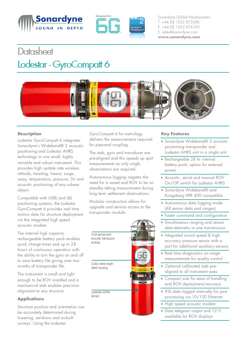
DatasheetLodestar - GyroCompatt 6DescriptionLodestar GyroCompatt 6 integrates Sonardyne’s Wideband® 2 acoustic positioning and Lodestar AHRS technology in one small, highly versatile and robust instrument. This provides high update rate wireless attitude, heading, heave, surge,sway, temperature, pressure, SV and acoustic positioning of any subsea object.Compatible with USBL and LBL positioning systems, the Lodestar GyroCompatt 6 provides real time motion data for structure deploymentvia the integrated high speed acoustic modem.The internal high capacityrechargeable battery pack enablesquick charge times and up to 28 hours of continuous operation with the ability to turn the gyro on and off to save battery life giving over two months of transponder life. The instrument is small and light enough to be ROV installed and a mechanical stab enables precision alignment to any structure. ApplicationsStructure position and orientation can be accurately determined during lowering, set-down and as-built surveys. Using the LodestarGyroCompatt 6 for metrologydelivers the measurements required for pipe-end coupling.The stab, gyro and transducer are pre-aligned and this speeds up spot measurements as only single observations are required.Autonomous logging negates the need for a vessel and ROV to be on standby taking measurement during long term settlement observations. Modular construction allows for upgrade and service access to the transponder module.Key Features• Sonardyne Wideband® 2 acoustic positioning transponder andLodestar AHRS unit in a single unit • Rechargeable 28 hr internal battery pack; option for external power• Acoustic, serial and manual ROV On/Off switch for Lodestar AHRS • Sonardyne Wideband® and Kongsberg HPR 400 compatible • Autonomous data logging mode (All sensor data and ranges) • Faster command and configuration • Simultaneous ranging and sensordata telemetry in one transmission • Integrated sound speed & high accuracy pressure sensor with a port for additional auxiliary sensors • Real time diagnostics on range measurements for quality control • Optional calibrated stab pre-aligned to all instrument axes • Compact size for ease of handling and ROV deployment/recovery • INS data logged internally for post processing via 10/100 Ethernet • High speed acoustic modem • Data telegram output and 12 V available for ROV displaysacoustic transducer endcap3,000 metre depth rated housingsensorSpecifications subject to change without notice - 06/2015SpecificationsLodestar - GyroCompatt 6Feature Type 8084-000-3164 Depth rating3,000 Metres Operating Temperature -10ºC to +50ºCOperational Shock Rating22 g, 11 ms half sine External Battery Pack / ROV Supply 24 V (20 – 50 V) Battery Life Acoustic Navigation StandbyLodestar Permanently Powered On3 Months 28 HoursAcoustic Compatt 6 Operating FrequencyMF (19-34 kHz) Sonardyne Wideband®2 Transmit Source Level 185-192 dB re 1µPa @ 1m (5 Levels) Ranging Precision Better than 15 mmTelemetry Protocol Sonardyne SMS and Modem Ranges Tracked14 Simultaneous Replies Lodestar AHRS Heading Range0-360ºAccuracy 0.04 to 0.1º Secant Latitude Settle Time<5 Minutes Follow Up Speed 500º / Second Resolution0.01ºRoll and Pitch Range±180º (No physical limit) Accuracy 0.01º Resolution0.01º Heave Range±99 mAccuracy (Real Time) 5 cm or 5% (Whichever is the greater) Bandwidth User selectable Resolution0.01 m Digital Output Output Telegram (e.g. For ROV LED display) Yes ROV Switch Contact Closure YesData Back-up Data Logger 8 GB (expandable to 32 GB) internal memory to allow post processing Remote Transducer For ROV applications, a remote transducer is available Sensors Sound Speed Sensor±0.03 m/s Pressure – Strain Gauge or Digiquartz 0.01% FSPhysical Size (Diameter x Length)247.8 mm x 917.2 mmWeight in Air / Weight in Water45 kg / 17 kg。
亚特兰蒂斯科普科技 Tensor SRB 低反应紧固件工具说明书

Choosing the right tool – for low reaction tighteningWhat is important in your tightening process?Tensor SRB is able to deliver all kind of tightening technologies with one-handed operation: with accuracy, traceability and flexibility, it does so powered by the new battery generation from Atlas Copco.The TBP is a true game changer. A reliable and powerful workhorse, offering high torque tightening, giving you speed, accuracy, traceability and flexibility … with cordless freedom.Take care of quality tightening – while taking good care of the operator. Low Reaction Tools eliminate the reaction forces, greatly improving operator comfort and delivering high speed tightening.Choosing the right tool is the first – and most important – step towards a perfect operation. Regardless of which of these three tools you use, you will have a well balanced ergonomically designed high quality tool. And choosing the right one will make the whole world of a difference for your specific needs.If you are looking for a low reaction tool with maximum flexibility, high torque and the ergonomic benefits of having the lowest vibration on the market – a cordless and powerful Atlas Copco TBP is your tool of choice.For low reaction tightenings with lower torque you have the choice of working with Tensor SRB – both of them ergonomic, reliable and accurate.One handed, error proofed action – with Tensor SRBFeaturesA Operator feedback and batterystatus via LED indicatorB Total Flexibility, Direct Drive,TurboTight™ and Tensor Pulse C Easy to set up and assign VirtualStation with the Power Focus 6000D Incorporate speaker to improve operator feedbackE Well balanced tool that sitscomfortably in your operators handsF New boosting feature deliversthe required energy for a high speed motor up to 1 500 rpm G A buffer battery makes battery swaps trouble freeH Dual antenna, ready forindustrial environments, improves your connectivity J Rapid Backup Unit (RBU)functionalityK e y b e n e fi t s o fT en so rS RB H i g ha c c ur a c y F u l lt r a c ea b i l it yO n e h a n d e dc a b l e f r e e A l l k i nd o f s t r at e g i e s S l i m d e s i g n R e a dy f o ri n d u st r i a le n v i r o me n t s The cordless Tensor SRB will change the way you plan your assembly stations. Experience low reaction, one-handed operations – in an error-proof production.DACEJFGHBFeaturesA Operator feedback, includingbattery status, is provided with LED indicators – easily seen from operating positionB Well balanced tool that sitscomfortably in your operators handsC New pulse unit, less affected byoil leakage, with longer service intervalD An efficient ventilation prevents the tool from getting to warmE A buffer battery makes battery swaps trouble freeF The all new pulse unit delivers 6 000 rpmG Easy to set up and assign VirtualStation with the Power Focus 6000H Internal buzzer for audible feedbackJ Dual antenna, ready forindustrial environments, improves your connectivity K Rapid Backup Unit (RBU)functionalityTBP Pulse Tool – redefining what a pulse tool can doThe TBP will change everything you thought you knew about pulse tools. TBP is a cordless tool for one-handed operations, enabling error-proofproductions. And our DuraPulse TBP, making it your new favourite workhorse.K e y b e n e fi t s o f t heT BPB a tt e r y t o o l H i g h p r od u c t i v i t y H i g hT o r q u e H i g hAc c u r a c y N o r e a c t i o n L e s s m a i n t e n a n c e R e ad yf o r i n d u s t r i a l en v i r o m e nt s DEJBHFCAGKGuided Rotaction socketsOur Rotaction concept promotes the increasing demands regarding operators safety and non-marking tools.Thanks to the extra stability from the enlongated sleeve the socket is able to deliver the correct torque to the joint.The combination of free rotatingsleeves and newly developed covers for the connections "tool-to-socket" and "extension-to-socket" improve operators safety significantly.Rotaction is available for a large number of Atlas Copco’s electrical assembly tools.Taking good care of your operators safety while improving joint accuracyBeside a wide range of standard products customized solutions can be realized with our team in Tierp,SwedenThe Rotaction range covers:¥Numerous sockets, bit sockets, bits and nut setters with new, freely rotating protection sleeves ¥Various extensions with rotating protection sleeves¥Socket covers to bridge gaps between extension and socket ¥Stainless steel tool covers to close the gap between anglehead tools and socket or extensionWith Guided Rotaction the yellow sleeve stays stationary while the socket rotates on the inside. This minimizes accidents and eliminates user influence on tightening. The socket extends past the square drive to give extra stability. This enables the socket to deliver the correct torque to the joint.Rotaction covered sockets ensure: ¥Safer operation for workers ¥Delivery of correct torque ¥Minimized risk of scratches and marks on painted surfaces ¥Low friction ¥High resistance to abrasion ¥Small outer dimension for better joint accessibilityC o r r e ct to r q u ed e l i v e r e dN o i n j ur i e s f r o mt r a p p e d g l o ve s N o a c id e n t a ls c r a t ch i n gS m a l l ou t l e td i me n s i o n sTake care of your Based on your needs, you can choose between Protect, Stability, Uptime. Please Smart connected Low Reaction Tools. Smart Connected Assembly supports Industry 4.0 becoming reality. A reality where technology is easy to use and quickly delivers value.Increased uptime: Increase tool up-time by 78 % – combine traditional preventive maintenance – with a more data driven approach.Reduction in defects:With smart connected low reaction tools, you could see a reduction in defects and rework by 15%.New product Introduction: With Smart Connected Assembly, you canmaximize quality and speed while bringing costs forintroduction of new products down by 57%!Improved productivity: Reduce reworks, minimize defects and maximizeoutput. By using real data, a big improvement in quality will be reached. And aproductivity increase by 73%.Human factors: Smart tools means less money and 30% less time spent on training, since your operators will have real-time guidance as they work.Reduction in energy use:Atlas Copco Power Focus 6000 can be connected to 6 tools – saving energy costs in standby with up to 80%.A Virtual Station to fit your exact needsWith Virtual Stations we are reinventing tightening, withdefined packages for each tool and functionality level. “One controller – Any tool”. This flexible controller manages up to six virtual stations – each of them managing different levels of functionality.Gain total tool control with virtual stations making sure your tool is performing correct tightenings for your assembly.Control your communication with the virtual station, giving you an easy and seamless integration with your production systems.Multiple accessories per virtual station are controlled –independently from other virtual stations.9833 2109 01ModelSquare Drive Guide Socket Torque range Battery Speed r/min Weight excl. battery Weight inc. battery Length mm Height mm Ordering No.Nm ft lb kg lb kg lb ETP SRB 31-20-103/8125-20 3.7-14.7518 V 1500 1.15 2.53 1.65 3.632232118433 3270 30ETP SRB31-20-I063/8125-20 3.7-14.7518 V 1500 1.33 2.93 1.83 4.032232418433 3270 31ETP SRB 31-20-10-BD 3/8125-20 3.7-14.7518 V 1500 1.33 2.93 1.83 4.032232418433 3270 32ETP SRB 31-25-103/8135-25 3.7-18.418 V 1500 1.15 2.53 1.65 3.632232118433 3260 30ETP SRB31-25-I063/8135-25 3.7-18.418 V 1500 1.33 2.93 1.83 4.032232418433 3260 31ETP SRB 31-25-10-BD 3/8135-25 3.7-18.418 V 1500 1.33 2.93 1.83 4.032232418433 3260 32ETP TBP61-32-103/81312-359-2618 V 6000 1.30 2.90 1.80 4.002002318433 3230 20ETP TBP61-32-10-BD 3/81312-359-2618 V 6000 1.48 3.30 1.98 4.402002618433 3230 21ETP TBP61-32-421/41312-359-2618 V 6000 1.33 2.90 1.83 4.002002318433 3230 22ETP TBP61-32-42-BD 1/41312-359-2618 V 6000 1.48 3.30 1.98 4.402002618433 3230 23ETP TBP81-55-103/81320-5515-4118 V 6000 1.50 3.30 2.00 4.402002318433 3230 30ETP TBP81-55-10-BD 3/81320-5515-4118 V 6000 1.68 3.70 2.18 4.802002618433 3230 31ETP TBP91-80-131/21830-8022-5936 V 6000 1.80 3.90 2.50 5.602102318433 3230 40ETP TBP91-80-13-BD 1/21830-8022-5936 V 6000 1.98 4.40 2.68 5.902102618433 3230 41ETP TBP131-150-131/21855-15041-11136 V 3600 2.80 6.20 3.507.902272558433 3230 60ETP TBP131-150-13-BD1/21855-15041-11136 V36002.986.603.688.302272858433 3230 61ModelMax TorqueTensor Pulse Turbo Tight Direct Drive Ordering No.Nm ft lb Nm ft lb Nm ft lb Nm ft lb ETP SRB 31-20-102014.751611.82014.75128.88433 3270 30ETP SRB 31-25-102518.42518.42014.7512*8.88433 3260 30Model Length mm Square Drive Ordering No.Extension 1001003/84027 1234 72Extension 1501503/84027 1234 74Extension 2502503/84027 1234 77Model Length mm Square Drive Ordering No.Socket 88503/84027 1292 08Socket 1010503/84027 1292 10Socket 1212503/84027 1292 12Socket 1313503/84027 1292 13Socket 1616503/84027 1292 16Socket 1717503/84027 1292 17BatteriesOrdering No.Battery Li-Ion 18V 2.6 Ah 4211 6030 85Battery Li-Ion 36V 2.6 Ah 4211 6030 86Multicharger 18-36V 4211 6083 84Daisy chain cable4211 6083 60AccessoriesOrdering No.Protective cover TBP6 & TBP84250 3135 60Protective cover TBP94250 3135 62Protective cover TBP134250 3135 63SRB/TBP Tool Holder 4220 3584 86 Protective cover SRB4220 2744 07AccessoriesOrdering No.Foot protective cover 4211 6089 00Protective cover 18V 4211 6090 18Protective cover 36V 4211 6090 36STB Battery Charger Adapter4211 6083 87Guided Rotaction Extensions 13 Accessories Atlas Copco AB(publ) SE-105 23 Stockholm, Sweden Phone: +46 8 743 80 00Reg. no: 。
CorePro LED下光灯CP6 产品介绍说明书

Features1. Reflector/Flange: One piece self flange cast aluminum, powder coated, non yellowing, white baffle and flange.2. Lens: High transmittance lens allowing for smooth, diffused light pattern.3. Power supply: Class 2 driver. Factory wired electronic LED driver (see Electrical section for specifications).4. LED board: Light emitted source.5. Friction spring: Stainless steel.6. Power connection: Trim features quickconnect plug installed as standard installation into CP6RN and CP6RR housings with mating connector. Trim ships with a medium base socket adapter whip for installation into 6" incandescent housings with medium base sockets. 7. Lifetime: Expected lifetime 50,000 hours and backed by a 5-year warranty (see /warranties for details).ElectricalElectronic power supply: RoHS compliant* Class 2 power unit for use in a dry and damp locations. Complies with FCC.Dimming: All luminaires are intended for use with TRIAC type dimmers. Go to /MKACatpdfs/LED-DIM.PDF for the latest dimming switch capability information. 10%-100% dimming range.Lumen Output Input Voltage Input Frequency Max. Input Current Max. Input Power Max THD Power Factor Min. Temp. Operating 835 lm 120 V 50/60Hz 0.11A 11W < 30% > .9 -20° C 1,200 lm120 V50/60Hz0.11A14W< 30%> .9-20° CPerformance data based on 80 CRI 3000K.* Restrictions on Hazardous Substances (RoHS) is a European directive (2002/95/EC) designed to limit the content of 6 substances [lead, mercury, cadmium, hexavalent chromium, polybrominated biphenyls(PBB), and polybrominated diphenyl ethers (PBDE)] in electrical and electronic products. For products used in North America compliance to RoHS is voluntary and self-certified.LabelscULus listed for wet locations.Energy Star certified.Title 24 Certified to meet high efficiencyrequirements; 90 CRI configuration only.Ordering guideexample: CP6RB07830WCatalog NumberApertureCRICCTLumensSystem Watts (Max)Efficacy (lm/W)VoltageCP6RB07830W 6-inch 803000 K 835 lm 1175120CP6RB10930W 6-inch 903000 K 1,000 lm 1663120CP6RB10830W 6-inch 803000 K 1,200 lm 1486120CP6RB10840W6-inch804000 K1,250 lm1489120Core value LED downlight for new construction and remodel applications that installs in many existing residential and commercial applications.DownlightingCP6RN: 6" IC/Airseal frame-in kit housingHousing - Constructed of formed aluminum. For use in direct contact with thermal insulation. Adjusts vertically in plaster frame to accommodate ceilings 1/2" to 1-1/2" thick. Ceiling opening 6-3/8".Electrical Connection - LED quick-connect adapterJunction Box - galvanized steel with two snap-on covers and grounding pigtail. Knockouts for 1/2” & 3/4” conduit and Romex knockouts with strain relief Bar Hangers: Pre-installed pre-nailed style bar hangers telescope from 16" to 24". Vertical design of interlocking bar hangers prevents sagging even at full 24" extension. Style bar hangers may be used on either long or short axis of housing.IC frame-in Kit - Housing is cULus Listed for direct contact with thermal insulation cULus Listed for Damp Locations and Through Branch Wiring, 4 in/4 out.AirSeal™: Fixture is AirSeal™ rated according to ASTM E283 to no more than 2.0 cubic feet of air per minute at 75 pascals. Fixture meets Washington State Energy Code and Energy Conservation Code.CP6RR: 6" IC/Airseal Remodeler HousingHousing - Constructed of formed aluminum. Adjusts vertically in plaster frame to accommodate ceilings 1/2”to 1-1/4” thick. Housing can be pulled through plaster frame for access to junction box. Ceiling opening of 6".Electrical Connection - LED quick-connect adapterJunction Box - galvanized steel with two snap-on covers and groundingpigtail. Knockouts for 1/2” & 3/4” conduit and Romex knockouts with strain relief IC Frame-in Kit - Housing is cULus Listed for direct contact with thermal insulation cULus Listed for Damp Locations and Through Branch Wiring, 4 in/4 out.AirSeal™: Fixture is AirSeal™ rated according to ASTM E283 to no more than 2.0 cubic feet of air per minute at 75 pascals. Fixture meets Washington State Energy Code and Energy Conservation Code.* A ny other luminaires meeting theses dimensions as shown are also compatible.E26 Compatibility*CP6RN: IC c/w LED Connector New Construction HousingCP6RR: IC c/w LED Connector Remodeler HousingDimensions6"unit shown with standard (E26) adapter to fit medium base sockets1. Correlated Color Temperature within specs as defined in ANSI_NEMA_ANSLG C78.377-2008: Specifications for the Chromaticity of Solid State Lighting Products.2. W attage: controlled to within 5%3. T ested using absolute photometry as specified in LM79: IESNA Approved Method for the Electrical and Photometric Measurements of Solid-State Lighting Products.© 2019 Signify Holding. All rights reserved. This document may be subject to change. Signify North America Corporation Signify Canada Ltd.。
蓝色曲线与蜂窝六边形背景的产品介绍PPT模板

产品特点
关键词 | 关键词
产品特点
填写段落标题您的内容打在这里,或者通过复制您的文本后,在此框中选择粘贴,并选择只保留文字。您的内容打在这里,或者通过复制您的文本后,在此框中选择粘贴,并选择只保留文字。
填写段落标题您的内容打在这里,或者通过复制您的文本后,在此框中选择粘贴,并选择只保留文字。您的内容打在这里,或者通过复制您的文本后,在此框中选择粘贴,并选择只保留文字。
添加标题内容
您的内容打在这里,或者通过复制您的文本后,
添加标题内容
您的内容打在这里,或者通过复制您的文本后,
添加标题内容
您的内容打在这里,或者通过复制您的文本后,
添加标题内容
您的内容打在这里,或者通过复制您的文本后,
添加标题内容
您的内容打在这里,或者通过复制您的文本后,
添加标题内容
您的内容打在这里,或者通过复制您的文本后,
填写段落标题您的内容打在这里,或者通过复制您的文本后,在此框中选择粘贴,并选择只保留文字。您的内容打在这里,或者通过复制您的文本后,在此框中选择粘贴,并选择只保留文字。
填写段落标题您的内容打在这里,或者通过复制您的文本后,在此框中选择粘贴,并选择只保留文字。您的内容打在这里,或者通过复制您的文本后,在此框中选择粘贴,并选择只保留文字。
展望未来
A dream need to work out a summary report dream need to work out a need to work out a summary report summaryA dream need to work out a summary
成员姓名
成员姓名
成员姓名
成员姓名
rock eval 6方法描述

Rock Eval 6方法描述一、Rock Eval 6方法简介Rock Eval 6方法是一种用于评估岩石有机质丰度和有机质类型的常用技术。
它通过热模拟实验来分析样品中的有机质含量、有机质类型以及热模拟条件下产生的油、气和残留烃等信息,从而为石油地质勘探和储层评价提供重要参考。
二、Rock Eval 6方法原理Rock Eval 6方法主要原理是通过四个步骤的热模拟实验来评估样品的有机质特征:1. Rock Eval 6方法首先进行岩心样品的加热,以模拟地下深部环境下的温度变化。
通过热模拟可以得到样品在不同温度下对应的有机质热演化过程,为后续分析提供基础数据。
2. 在加热过程中,样品会释放出挥发油和气体。
Rock Eval 6方法通过精密的仪器装置对这些挥发物进行分析,得到有机质在高温条件下的裂解产物信息。
3. Rock Eval 6方法对样品进行热氧化实验,模拟地下埋藏条件下的氧化环境。
通过这一步骤可以得到样品在氧化状态下的裂解产物信息。
4. Rock Eval 6方法对残留岩石样品进行分析,得到其有机质残留量和残留质地。
三、Rock Eval 6方法的应用Rock Eval 6方法广泛应用于石油勘探、储层评价、沉积环境研究等领域。
具体包括以下几个方面的应用:1. 评价有机质丰度:Rock Eval 6方法可以准确测定岩石中的有机质含量,为勘探油气资源提供重要依据。
通过分析样品在不同温度下的裂解产物,可以得到有机质丰度指标,包括Tmax值、S1和S2含量等。
2. 鉴定有机质类型:Rock Eval 6方法可以分析样品中有机质的类型,包括干酪根类型、成熟度等。
通过对样品在不同温度下的裂解产物进行定量分析,可以得到有机质类型和烃源岩类型。
3. 确定油气生成潜力:Rock Eval 6方法可以评估地层中有机质的热模拟裂解过程,从而确定烃源岩的油气生成潜力。
通过分析挥发物和氧化产物的组成和分布,可以预测油气的产出潜力。
美国进口多通道农业多光谱相机

美国进口多通道农业多光谱相机ALTUM六通道多光谱相机产品简介:新型Altum六通道相机将辐射热像仪与五个高分辨率窄带相结合,在一次飞行中产生先进的热多光谱和高分辨率图像,以进行高级分析。
Altum套件附带:Altum传感器,镜头盖,外部存储设备(USB 3.0)-128GB,校准反射面板,带集成GPS的新DLS 2光传感器,电缆,安装螺丝,硬质便携包。
一个传感器,即可完成三种工作。
仅需要使用一个传感器、单次飞行,即可捕捉含植物健康、表型(phenotype)、水分胁迫及更多的数据。
Altum生成的图像,不仅仅可以确认哪些您已经知道的,它多层的数据可以让您解决多方面的问题。
Altum向研究人员、企业级的种植人员,打开了高级分析的大门,让服务提供者有能力去接受复杂项目的挑战。
只需要一次飞行,Altum就能产生热敏、多光谱和高分辨率的图像,从一个数据集成表去分析,灌溉和植物健康状况。
单次飞行,即可捕捉关于植物健康、表型和水分胁迫的数据。
大容量的USB存储可以让无人机飞更长时间并覆盖更多种植面积,无需更换SD卡。
通过多个接口选项和嵌入式安装点进行集成,非常简单。
Rededge-mx五通道多光谱相机主要特色飞行期间,可以捕捉5个窄的光谱带。
高图像分辨率;120 m(400 ft)时每像素8 cm。
单个SD卡,可存储带地理标志的所有图像。
可独立操作,带可选的外部触发器,和来自主机的数据。
可以从任何支持Wi-Fi的设备,访问基于网络的配置页面。
嵌入式安装点,集成更简单。
全域快门成像仪-不需要万向的常平架全新RedEdge-MX多光谱相机铝合金机身,拥有更好的耐用性和散热性DLS 2(带12个传感器,强化了光校准);内置了GPS,无需额外再使用GPSDLS 2 。
由于配有一个集成的GPS,DLS 2是我们*精zhun的阳光传感器。
凭借尖端的专li技术,它提供更精zhun和可靠的数据主要优势全新的铝合金机身,拥有更好的耐用性和散热性。
英国安道尔公司高性能光谱解决方案

出众的多通道成像性能
1200
1 mm
1000
800
600
400
200
0
1.5
2.0
2.5
3.0
3.5
4.0
4.5
5.0
Position (mm)
1400
13 mm
1200
1000
800
600
400
200
0
1.5
2.0
2.5
3.0
3.5
4.0
4.5
5.0
Position (mm)
1400
24 mm
1200
倍。
收集更多的光子:
✓ 更好的信噪比 ✓ 更短的曝光时间
F/4.6 CZ F/4 CZ (320 mm focal length) (300 mm focal length)
能够从最常用的光纤(NA=0.22)中收集100%的信号
12
体全息相位透射光栅技术
极低的杂散光- 平滑的正弦折射率分布
带来最纯净的信号水平,增大动态范围和信噪比
nm
0.77 nm / 529 nm 0.43 nm / 297 nm 0.26 nm / 177 nm 0.18 nm / 120 nm 300 l/mm @ 500 nm 300 l/mm @ 500 nm 300 l/mm @ 500 nm 300 l/mm @ 500 nm
21
应用领域
固有的弱光实验
37
Shamrock 500i/750 改进型
➢ “光栅塔伦倒转” 设计
➢ 减少潜在的由于光栅衍射角度较大时所产生的杂散光 ➢ 在较大光栅角度时更好的光通量
Low directed stray-light
- 1、下载文档前请自行甄别文档内容的完整性,平台不提供额外的编辑、内容补充、找答案等附加服务。
- 2、"仅部分预览"的文档,不可在线预览部分如存在完整性等问题,可反馈申请退款(可完整预览的文档不适用该条件!)。
- 3、如文档侵犯您的权益,请联系客服反馈,我们会尽快为您处理(人工客服工作时间:9:00-18:30)。
LanderCluster
6
Keep system working Start from
Here
智慧高可用集群
议题
当前企业业务流程
IT风险
现已成为业务风险
IT机遇
也成了业务机遇
80%的业务流程依赖于IT
总资本投入中IT 所占的份额
IT 运营支出
50100150200250'02
'03
'04
'05
'06
'07
'08
存储
服务器
管理和运营
当前企业系统运行现状
哎呀,我们的业务正进行中
呢,怎么突然停了?不及时
恢复客户又要骂我们了,您
赶紧帮忙查查,别再断断续
续了,已经过来投诉电话了
业务经理
数据中心好,我们马
上过去看看
IT经理
IT 经理
几个小时后,系统恢复了正常
同时,IT 经理又开始担忧了起来……
这么多的服务器,这么多的应用,这么多的存储设备,今天这里停一下,明天那里
停一下
一台台排除故障,我们IT 部还有没有喘气的时间了,累点没什么,业务还怎么开
展?
有什么方法才能保持系统持续不间断工作?
?
影响核心系统安全运行的风险
40%硬件故障31%软件故障20%用户错误9%其他错误
40%
31%
20%
9%
影响核心系统安全运行的风险
发生原因计算机软硬件故障
◆人为操作失误
◆电脑病毒
◆黑客入侵
◆失窃
资源不足引起的计划
性停机。
生产地点自然灾害。
产生原因
硬件失效(如cpu毁坏)。
软件设计缺陷——操作系统和
应用程序有时存在缺陷使数据被
破坏(如Y2K问题)。
人为因素不可避免——
失误可以很容易地删除重要
数据。
外面的系统破坏者在蓄
意攻击系统。
业务的快速增长。
火灾、闪电、水灾、
飓风、龙卷风以及
地震都可能发生。
发生概率可能性最大、最频繁。
经常发生、与企业人员、网
络设计有关。
业务增长越快的企业,
发生亦越频繁。
发生概率较小。
预防方法实现硬件冗余,提高业务系统的
高可用。
提高人员素质和系统自动化
运行管理,加强网络安全防
范。
系统设计考率业务的
发展。
异地保存。
具体措施◆磁盘阵列
◆本地集群
◆数据冷备份
◆安装杀毒软件
◆网络防火墙
本地双机热备份、增
加硬件资源、软件升
级。
◆异地集群
◆数据同步
◆灾难恢复中心。