LRB-10说明书
BW10红光源中文说明书

3、激光器工作时,光纤接头应处理干净,否则会影响使用效果;
4、不使用本光源时,请将防尘帽戴好以避免灰尘落入;
5、人为使用不当造成的损坏,如:摔、碰或自行拆卸不在保修范围内,维修需收取成本 费;
6、出厂日期小标签请勿撕毁,否则,本公司不提供售后服务。 五、产品参数
产品型号 工作波长 发光器件 谱宽(20℃) 光纤类别 测试接口 输出功率(mW) 工作温度(℃) 存储温度(℃) 外壳材料
2、将笔尾与笔身连接装好,打开防尘帽,按控制开关一次,观察光接口有红光光出来,
同时指示发光管点亮;(注意不要眼睛正对光接口,以免损伤眼睛)。
3、再按控制开关一次,观察出光变为脉冲模式,指示发光管与出光同步脉冲;(脉冲频率
在 0.5~2 赫兹)。
4、再按控制开关一次,光源关闭,无光输出,同时指示发光管熄灭;(开关模式为:连续
1、型号:BW-10-A/T/G-X
2、材质:A-铝合金,T-铜合金,G-不锈钢
3、输出功率(mW):X=5、10、20、30
BW-10-A
BW-10-T
BW-10-G
-脉冲-关闭-连续的循环模式)。
5、检测时将被测光纤插入光接口,同时按控制开关,选择输出光源工作模式(连续或脉
冲)。
6、使用完毕,将防尘帽盖起,长时间不使用,请将电池取出,以免电池腐烂,损坏光源。
四、维护与注意事项
1、激光有害,尤其要注意保护眼睛,激光器工作时,避免激光直射眼睛;
2、一般情况下,温度越高,激光器寿命越短,使用时尽量避免高温工作环境;
适用光纤:SM、MM
检测距离:5公里~20公里
电源:2节1.5V电池
电源连续工作时间:≥10h
工作温度:-10~+60℃(不结露)
Olight 闪光灯 MH10 用户手册说明书

User Manual®The All-Round Flashlight ExpertMH10Features·Utilizes a CREE XM-L2 U2 LED·Maximum output of up to 1000 lumens·Integrated “Precision Digital Optics Technology” provides extreme reflector performance·Boasts a peak beam intensity of 13,500 cd and a throw distance of up to 232 meters·Innovative single button offers access to four brightness levels and three special modes·High efficiency constant current circuit provides max runtime of 520 hours ·Integrated power indicator light displays remaining battery power (patented)·Power indicator’s secondary function displays battery voltage (accurate to 0.1V)·Charging module with a micro USB port charges Li-ion batteries rapidly ·Direct access to ultra-low output·Reverse polarity protection prevents damage from incorrectly inserted batteries ·Constructed from aero grade aluminum alloy with HAIII military grade hard-anodized finish·Waterproof in accordance to IPX-8 (two meters submersible)·Impact resistant to 1.5 meters ·Tail stand capabilityDimensionsLength: 130mm (5.12”)Head diameter: 25.4mm (1”)Tube diameter: 25.4mm (1”)Weight : 75g (2.65oz)(without battery)brightness level, simply release the switch when that level is being displayed. This mode has memory effect to ensure direct access to the previously used brightness level when the MH10 is resumed.Direct access to ultra-lowWith the MH10 switched off, press and hold the switch for more than 1 second to enter ultra-low output (1 lumen);Note: When in high output, the MH10 will reduce output luminance automatically after 5 minutes of use to prevent overheating and extend battery longevity.Special Modes (Strobe/SOS/Location Beacon)Press the switch twice in quick succession in any state to enter strobe mode. When in strobe mode, press and hold the switch for more than 1 second to cycle through SOS, location beacon and strobe modes. To exit, simply press the switch again. The MH10 does not have memory effect in any of these special modes.Charging FunctionThe MH10 is capable of charging one 18650 Li-ion battery with the included USB charging cable. Connect the USB cable to the MH10's charging port and a powersource (USB chargers, PC or other power terminals) as shown in the adjacent image.Fully charging one depleted 18650 battery takes approximately 6 hours.Thanks for purchasing NITECORE!Output & RuntimeNOTICEThe stated data has been measured in accordance with the international flashlight testing standards ANSI/NEMA FL1, using 1xNitecore 18650 battery (3.7V, 2600mAh) or 2xNitecore CR123 batteries (3V, 1700mAh) underlaboratory conditions. The data may vary in real-world use due to different battery use or environmental conditions.NITECORE (SYSMAX) is a member of PLATO, participating in and helping to develop the ANSI FL1 standard of measurement. Product testing data is in accordance with Operating InstructionsBattery installationInsert 1x18650 battery or 2xCR123 batteries as illustrated.Note: After loading batteries, the bluevoltage.Please refer to “Power Tips” section of this manual for details.WARNING1. Ensure batteries are inserted with the MH10 will not be operational with incorrectly inserted batteries.SYSMAX Industry Co., Ltd.TEL: +86-20-83862000 FAX: +86-20-83882723 E-mail: *****************Web: Address : Rm1401-03, Glorious Tower, 850 East Dongfeng Road,Guangzhou, China 510600Changing /Charging BatteryBatteries should be recharged or replaced when any of the followings occurs: The power indicator blinks rapidly, output appears to be dim or the flashlight becomes unresponsive.MaintenanceEvery 6 months, threads should be wiped with a clean cloth followed by a thin coating of silicon-based lubricant.Warranty ServiceAll NITECORE® products are warranted for quality. Any DOA/defective product can be exchanged for a replacement through a local distributor/dealer within the 15 days of purchase. After 15 days, all defective / malfunctioning NITECORE® products can be repaired free of charge for a period of 60 months (5 years) from the date ofpurchase. Beyond 60 months (5 years), a limited warranty applies, covering the cost of labor and maintenance, but not the cost of accessories or replacement parts.The warranty is nullified in all of the following situations:1. The product(s) is/are broken down, reconstructed and/or modified by unauthorized parties.2. The product(s) is/are damaged through improper use.3. The product(s) is/are damaged by leakage of batteries.For the latest information on NITECORE® products and services, please contact a localNITECORE®**********************************************.The Nitecore official website shall prevail in case of any product data changes.Please follow our facebook for more info: NITECORE Flashlights4.2V3.5V3.7V 3.9V Full powerLow powerFull power Low power1 x 18650 battery2 x CR123 batteriesHIGHMIDLOWLUMENS240LUMENS1000LUMENS70LUMEN11h 15min28h 6hLOWER520h 5h 15min300h20h1h232m (Beam Distance)13500cd (Peak Beam Intensity)IPX-8, 2m (Waterproof AND Submersible)1.5m (Impact Resistant)1×186502×CR12320150112AccessoriesNitecore NL183 battery, USB charging cable, holster, clip, lanyard, spare USB port cover, spare O-ringleft unused for extended periods of time, Nitecore recommends all batteries are removed to prevent accidental activation of the flashlight or battery leakage.ON/OFFTo switch ON: Press the switch until a click is heardTo switch OFF: Press the switch once again until a click is heardBrightness LevelsWith the MH10 switched on, press and hold the switch for more than 0.5 second to cycle through brightness levels of ultra-low, low, medium and high. To select a desiredUnder normal charging conditions, the blue power indicator light will illuminate steadily to notify users. When charging is complete, the MH10 will terminate the charging process automatically and the blue power indicator goes out.Power Tips1. When the light is on, the power indicator will blink once every two seconds when power level drops to 50%; the power indicator will blink quickly when power level is low.2. After battery installation, the blue power indicator will blink to indicate battery voltage (accurate to 0.1V). For example, when battery voltage is at 4.2V, the blue power indicator will blink 4 times, followed by a one second pause and another 2blinks. Different voltages represent the corresponding remaining battery power levels:。
ASB-10 窄边框电视配音棒说明说明书

What is a Big tV Without Big sound?Your new slim TV may well deliver ever wider more enveloping pictures,but have you noticed how puny it sounds? Size limitations imposedby shrinking TV bezels mean that the speakers within them reproduceonly a fraction of the bandwidth available from today’s DTV boxes,games consoles and media players. Our new ASB-10 compact ActiveSound-Bar system, complete with optional active subwoofer and wide-ranging wireless functionality, is expertly engineered to re-energise HDand UHD pictures with the rich, detailed, immersive sound you’ve beenmissing. Easily and oh so discreetly, your experience of TV is about tobe transformed.MoVies, Music and Magic froM the asB-10Equipped with a precision-tuned high performance 2.0 audio design comprising proprietary driver/amp pairings, integrated Dolby Digital processing and superior Bluetooth aptX™ wire-free streaming, the super-slender ASB-10 will generate big audio dynamics from TV, games, discs and smartphones, to become the audio hub for every home.PoWer, Precision, PerforMance in oneWith a compact 90 x 94mm cross section and at just under a metre in length, the discreetly proportioned ASB-10 complements the look of flat screens from wall or table-top positions. Its slim moulded polymer cabinet with black cloth grille and stylish brushed aluminium end trims houses an array of four Monitor Audio 3” C-CAM® bass drivers (assisted by a brace of passive bass radiators), and twin 25mm Gold Dome C-CAM tweeters. The ASB-10’s proprietary drive-unit configuration is powered by as many as four integral DSP-trimmed amplifiers, individually calibrated by Monitor Audio engineers for optimum audio control and response. From so svelte a system the result is a size-defying success, injecting your music and film sound with greater scale, detail and rhythmic mid-bass definition.easy setuP and oPerationInstallation couldn’t be any simpler. A single, easy, optical or coaxial SP-DIF link to the TV allows the ASB-10 to decode digital audio from connected sources. Activated automatically when a signal is received, the ASB-10’s on-board Dolby Digital and Dolby Pro-Logic II decoding ensures wide compatibility with film and games content. Dolby’s Virtual Speaker processing, which is designed to replicate a three-dimensional surround sound experience, is enabled via a button located on the front panel or remote handset. In addition the ASB-10 will energise streams of uncompressed CD-quality audio from your smartphones and tablets through its effortless Bluetooth aptX wireless technology, and also accept legacy analogue sources via a 3.5mm stereo input.eVen Bigger Bass if you need it…In most circumstances the ASB-10 will deliver ample levels of bass, but for low frequencyenthusiasts Monitor Audio has developed the optional WS-10 active sub-woofer, purpose-builtto add big bass dynamics to the ASB-10 system and all space-efficient set-ups. Complete withthree-position EQ and a high quality digital wireless link to the ASB-10, the WS-10 is a compactand versatile design, comprising an 8” C-CAM driver powered by a 120 watt amplifier, generouslyprovisioned with individual volume and phase controls, and a standard array of wired LFE and12V inputs for integration with an AVR in alternative system applications. For ever greater systemdesign versatility, the WS-10 can connect wire-free to other systems via Monitor Audio’s new WT-1transmitter module.Equipped with twin HiVe reflex ports, the WS-10’s robust, low-profile cabinet of 18mm MDFis designed with flexibility in mind, wirelessly extending the ASB-10’s full-range delivery andcontributing deeper bass to any Sound-Bar or compact satellite system through wired or wirelessconnections from the widest range of discreet room locations: beneath furniture, along roomboundaries or in corners.Lose the Wires!Decades of dealing with long, ugly cable runs can be consigned to history in minutes by installing our diminutive new WT-1/WR-1 wireless link.Measuring just 6cm round by 4cm deep, the WT-1 transmitter and WR-1 receiver establish an automatic lossless audio connection betweenanalogue outputs and inputs over a range of up to 15 metres. The pairing is entirely intuitive and immediate: no elaborate button pushingis necessary.Tucked out of the way behind equipment, the WT-1 transmitter simply plugs into the analogue LFE or pre-outputs on your AVR or player, and theWR-1 receiver into the inputs of a remote subwoofer or amp. The unobtrusive, ultra-compact modules then use the 2.4GHz digital band to senduncompressed full-range audio through the air between them. Effortless installation replaces long runs of ugly wire to wirelessly extend thepower of our WS-10 active subwoofer, and enable full-range, wire-free performance and convenience in any set-up missing wireless functionality,but with idle analogue inputs and outputs.Simple to set-up and easy to use and expand, Monitor Audio’s super-flexible system of active ASB-10 Sound-Bar, optional companion WS-10 active subwoofer and WT wireless link applies over four decades of award-winning audio precision to restore the sound you’re missing from your TV and help you complete the high definition AV experience in your home. Easy, dynamic and beautifully discreet.Ws-10• Wireless Active subwoofer • Class D amplifier delivering 120W • 8” long throw C-CAM bass mid-range driver • Compact dimensions for flexible room positioning flat against a wall, in corners, under furniture etc • 2.4GHz receiver built-in for lossless/uncompressed audio reception in wireless applications • Analogue LFE input • Volume and phase controls • Bass EQ settings optimised for music, movie or impact • 12V trigger input (3.5mm jack) to provide automatic switch on from AVR or other equipped amplifier • Power selection switch for auto standby or trigger • Rigid MDF construction with black sand vinyl finish • Dual HiVe port system • Dimensions: 173 x 373 x 477mm including feetasB-10• 2.0 Active Soundbar• 100W delivered by four Class D amplifiers for ample power and clarity• Monitor Audio calibrated DSP processing provides precision filters andprocessing for all drivers individually• 4 x 3” C-CAM metal cone bass mid-range drivers• 2 x 25mm C-CAM Gold Dome tweeters• 2 x ABRs (Auxiliary Bass Radiators)• Compact dimensions for easy positioning beneath the TV, on-wall orcabinet location• Digital wireless 2.4GHz transmitter built-in for lossless/uncompressedsignal transfer to optional WS-10 sub• Bluetooth for easy music playback from smartphone, tablet or PCfeaturing high quality ‘CD like’ aptX codec• Dolby Digital, Dolby Pro-Logic II and Dolby Virtual Speaker processing• Optical and Coaxial SPDIF inputs• Analogue input (3.5mm stereo jack)• IR Remote control handset supplied• Moulded polymer cabinet with black cloth grille and brushed aluminiumend trims• Dimensions H x W x D: 99 x 900 x 94mmWhen you decide on Monitor Audio you’re getting so much more than fabulous wideband sound. By choosing any of our specialised systems you’re securing the utterly desirable union of life-like audio accuracy, acclaimed by the world’s most critical listeners, and wonderfully discreet design, perfected to blend with the fabric of your home. Since the 1970s we’ve dedicated our award-wining audio innovation to the challenge of integrating great sound with the way you live. When sound quality is a lifestyle choice, no other hi-fi brand offers a range of residential speakers as developed and diverse. Excellence is in our DNA; the experience is yours to enjoy for years to come.Monitor Audio Ltd 24 Brook Road,Rayleigh, Essex,SS6 7XJ EnglandT. + 44 (0)1268 740580F. + 44 (0)1268 740589**********************.uk。
10米钢管避雷针说明书

10米钢管避雷针使用说明书河南汇龙合金材料有限公司产品介绍通用电感避雷针能将有可能击中受保护物体的直击雷引至避雷针处,由接闪器接闪,并通过避雷针对空中放电逐步减弱雷电流,剩余雷电流通过引下结构将雷电流疏导入地进行泄流,在雷击时,利用感抗器件减缓雷电流冲击,降低脉冲幅度,延长放电时间,从而降低雷电流波形的陡度,降低雷电流冲击破坏能力,抑制削弱地电位反击和二次雷击效应对电子电器设备的冲击损害.适用于民用建筑物、别墅、小高层商用建筑、酒店、古建筑等场所,从而避免被保护物体免遭直击雷的侵袭。
二、产品参数:最大放电电流:300KA抗风强度:40m/s针径:Φ50mm 76mm总高:10000mm(可定制)材质:不锈钢避雷针,热镀锌杆体三、产品特点:■接闪器采用不锈钢;■抗腐蚀,外形美观,色泽亮丽;■防侧击;■结构坚固、抗风能力强;■通流容量大、抗雷电冲击能力强;■大幅度衰减冲击电流幅度;■模拟实验中延缓冲击电流陡度10倍以上;四、安装使用:1、安装方法:开启包装后,将避雷针下部放置于预留的安装位置上,使用M16×100的不锈钢螺栓配件安装紧固,也可根据需要进行焊接连接。
2、安装注意事项:■需确保避雷针与引下部分可靠的电气连接;■系统接地良好,其接地电阻应小于10欧姆;■被保护范围应根据《建筑物防雷设计规范》相关规定的滚球法进行计算。
避雷针安装方法简述:(建筑现场情况不同,安装方法也略有不同)采用独立避雷针保护时,避雷针尽量安装在屋顶靠中间最高位置。
如果避雷针保护面积不够,应采用多根避雷针保护。
避雷针应垂直固定牢固,垂直度允许偏差3/1000。
屋顶突起金属装置,应可靠于避雷针连接。
基座法兰用不少于4个M16*100膨胀螺栓牢固固定屋顶混凝土上,也可根据法兰盘孔位先做预埋件,基座法兰直接焊接在预埋件螺栓上。
避雷针引下装置:如屋顶柱子已经预留建筑物主钢筋,避雷针基座法兰用镀锌圆钢Φ12或镀锌扁钢25*4和建筑物主钢筋可靠的电气连接,焊接不少于对角2处预留引下主钢筋,焊接后涂抹沥青。
OncQue Tilt Switch V10 产品说明书

Item No. RBS040110 Description TILT SWITCHVersion 10Page1 of 10 DateSep. 25, 2015Tel: 886-4-23588178 No.1, Jingke 3rd Rd., Nantun Dist., Taichung● FUNCTIONS1. Horizontal Tilt Detecting2. Vertical Up-Side Down Detecting● APPLICATIONS1. Position Detection for Iron2. Lighting system for night time while car hold being opened3. Toys 、Entertainment Device● FEATURES1. Suitable for vertical PCB.2. Switch state : Normal Close.3. Housing made of high insulation plastic material, free from electric conduction andrust problem.4. Gold-plated ball and terminals, low possibility of oxidization.5. All plastic materials subject to industrial purpose, resist high temperature and meetfireproof function.6. Simple ON and OFF signals, easy for design.7. RoHS compliance, an ideal substitute for mercury switch.8. A more economical tilt and rotation detection option than IC design solution. 9. All made in Taiwan and examined before shipment.Item No. RBS040110 Description TILT SWITCHVersion 10Page2 of 10 DateSep. 25, 2015Tel: 886-4-23588178 No.1, Jingke 3rd Rd., Nantun Dist., Taichung● PATENTS1. TAIWAN NO. 1559652. TAIWAN NO. 4767973. U.S.A. PATENT NO. US 6,198,059 B14. U.S.A. PATENT NO. US 7,256,360 B15. U.S.A. PATENT NO. US 7,446,272 B26. U.S.A. PATENT NO. US 9,058,945 B27. CHINA PATENT NO. 201220308500.8Item No. RBS040110 Description TILT SWITCHVersion 10Page3 of 10 DateSep. 25, 2015Tel: 886-4-23588178 No.1, Jingke 3rd Rd., Nantun Dist., Taichung● DIMENSIONS / OPERATION / P .C.B. LAYOUT (Unit: mm, Tolerance: ±0.25mm)Fig. 1Item No. RBS040110 Description TILT SWITCHVersion 10Page4 of 10 DateSep. 25, 2015Tel: 886-4-23588178 No.1, Jingke 3rd Rd., Nantun Dist., Taichung● Current/Voltage SuggestedInput Current (mA)Operating Voltage (V)Condition1.0 5 --● ELECTRICAL CHARACTERISTICS 1. Contact Rating 10 mA, 5VDC 2. Contact Resistance 10 Ω max. 3.Differential AngleRefer to Fig. 14. Insulation Resistance 1000 M Ω min.,100 VDC5. Dielectric Strength 500 VDC min.,1 minute6. Capacitance 5pF max.7.Conductive Rate90% min.Item No. RBS040110 Description TILT SWITCHVersion 10Page5 of 10 DateSep. 25, 2015Tel: 886-4-23588178 No.1, Jingke 3rd Rd., Nantun Dist., Taichung● RELIABLE TEST ITEMSReliable Test for RBS040110Test ItemStandardContentsIR Reflow---- Operating TemperatureMIL-STD-202G,TEST METHOD 107G, TEST A -25℃~85℃Storage Temperature MIL-STD-202G,TEST METHOD 107G, TEST A -40℃~85℃ Humidity MIL-STD-202G,TEST METHOD 103B40℃/95%RH Mechanical Life -- 2 Hz horizontal 1,000,000 times Electrical Life--100,000 timesItem No. RBS040110 Description TILT SWITCHVersion 10Page6 of 10 DateSep. 25, 2015Tel: 886-4-23588178 No.1, Jingke 3rd Rd., Nantun Dist., Taichung● SOLDERING CONDITIONFollowing soldering conditions are for reference only, please use soldering information that solder paste manufacturer recommends.Item No. RBS040110 Description TILT SWITCHVersion 10Page7 of 10 DateSep. 25, 2015Tel: 886-4-23588178 No.1, Jingke 3rd Rd., Nantun Dist., Taichung< Table of classification Reflow profile >ItemPb process Pb free process Pre-heat and SoakTemperature min.(Tsmin) Temperature max.(Tsmax) Time (Tsmin to Tsmax)(ts)100 °C 150 °C60-120 seconds 150 °C 200 °C60-120 seconds Average Rate of temperature rising up(Tsmax to Tp)3 °C/second max. 3 °C/second max. Liquidous Temperature (TL) Time at Liquidous (tL)183 °C60-150 seconds 217 °C60-150 seconds Peak package body Temperature (Tp)*230 °C ~235 °C *255 °C ~260 °C *Classification temperature(Tc) 235 °C 260 °C Time(tp)** within 5 °C of thespecified classification temperature (Tc)20** seconds 30** seconds Average ram-down Rate (Tp toTsmax)6 °C/second max. 6 °C/second max. Time 25 °C to peak temperature6 minutes max.8 minutes max.* Tolerance for peak profile temperature (Tp) is defined as a supplier minimum and a user maximum. ** Tolerance for time at peak profile temperature (tp) is defined as a supplier minimum and a user maximum.Item No. RBS040110 Description TILT SWITCHVersion10Page8 of 10 DateSep. 25, 2015Tel: 886-4-23588178 No.1, Jingke 3rd Rd., Nantun Dist., TaichungFig. 2Item No. RBS040110 Description TILT SWITCHVersion 10Page9 of 10 DateSep. 25, 2015Tel: 886-4-23588178 No.1, Jingke 3rd Rd., Nantun Dist., Taichung● PACKAGEPart NumberPackage Quantity Total Size (mm) 1.RBS040110PE Bag500 pcs500 pcs 205L*145W Inner Box 10 PE Bag 5,000 pcs 348L*191W*85H Carton3 Boxes15,000 pcs364L*278W*213H※ Package shown as below for reference.PE BagInner BoxCartonItem No. RBS040110 Description TILT SWITCHVersion 10Page10 of 10 DateSep. 25, 2015Tel: 886-4-23588178 No.1, Jingke 3rd Rd., Nantun Dist., Taichung● NOTE1. Suggestion for usage :For vibration usage or application ,we suggest to add hysteresis for IC; if vibration is heavy ,optical type of sensor switch is recommended.2. For the continued product improvement as one of the company policy, specifications may change or update without notice. The latest information can be obtained through our sales offices. Normally, all products are supplied under our standard conditions.3. If buyer’s products will stay in power supply for a long time which needs very high stability, optical sensor switch is strongly recommended.● PRECAUTIONS FOR USE1. If the products is intended to be used for other endurance equipment requiringhigher safety and reliability such as life support system, space and aviation devices, disaster and safety system, it’s necessary to make verification of conformity or contact us for the details before using.2. Do not try to clean the switch with a solvent or similar substance after the solderingprocess.3. If soldering temperature exceeds our specification, sensor switch could get apart.4. Use water-soluble flux may damage the switch.5. Do not use switch in the environment of high humidity ,because such anenvironment may cause the leakage current between the terminals.6. More than the rated load may cause fire, so do not use more than the load.7. In the circuit ,switch should not be near or directly connected with the magneticcomponent solder joints (for example: relays, transformers, etc.).。
舒尔斯(Festo)压力调节器LR LRS LRB LRBS D系列产品介绍说明书

Pressure regulators LR/LRS/LRB/LRBS, D seriesPressure regulators LR/LRS/LRB/LRBS, D series, metalProduct range overview – Service unit components, D series, metal2d I nternet: /catalogue/...Subject to change – 2023/05Pressure regulators LR/LRS/LRB/LRBS, D series, metal Product range overview – Service unit components, D series, metal3 2023/05 – Subject to change d I nternet: /catalogue/...Pressure regulators LR/LRS/LRB/LRBS, D series, metalProduct range overview – Service unit components, D series, metal4d I nternet: /catalogue/...Subject to change – 2023/05Pressure regulators LR/LRS/LRB/LRBS, D series, metal Product range overview – Service unit components, D series, metal5 2023/05 – Subject to change d I nternet: /catalogue/...Pressure regulators LR/LRS, D series, metalPeripherals overviewMini/Midi/MaxiPressure regulator LR Pressure regulator LRS, lockable56d I nternet: /catalogue/...Subject to change – 2023/05Pressure regulators LR/LRS, D series, metalType codes72023/05 – Subject to change d I nternet: /catalogue/...8d I nternet: /catalogue/...Subject to change – 2023/05Pressure regulators LR/LRS, D series, metalDatasheetLR/LRSwith pressure gaugeLR/LRS-…-I-MINI/MIDI,LR/LRS-…-DI-MAXIWith pressure gauge-M- Flow rate120 ... 12500 l/min -Q- Temperature range –10 ... +60 °C -L-Operating pressure1 ... 16 bar• Also suitable for front panel mount-ing• Two pressure gauge connections for different installation options• Good regulation characteristics with minimal pressure hysteresis • High flow rate• Two pressure regulation ranges: 0.5°... 7 bar and 0.5 ... 12 bar • Settings secured via latch on rotary knob• Return flow option for exhausting from output 2 to input 1• Pressure sensor (optional) apage 501)Connecting plates with threaded connection 2) For LR/LRS-...-I.3) For LR/LRS-...-DI.-H- Note: This product corresponds to ISO 1179-1 and ISO 228-1.Pressure regulators LR/LRS, D series, metal Datasheet1) Measured at p1 = 10 bar, p2 = 6 bar and Δp = 1 bar.Support/Downloads.2) More information: /catalogue/lr dMore information /x/topic/crc9 2023/05 – Subject to change d I nternet: /catalogue/...Pressure regulators LR/LRS, D series, metalDatasheetMaterialsSectional view 10d I nternet: /catalogue/...Subject to change – 2023/05H--NoteIn order to improve the control per-formance, internal air consumption depending on the primary pressure is integrated into the design of theLR/LRS-...-MAXI.-H-Note: This product corresponds to ISO 1179-1 and ISO 228-1.1) A mounting bracket must be fitted after every second pressure regulator.Pressure regulators LRB/LRBS, D series, metal Peripherals overview1) A mounting bracket must be fitted after every second pressure regulator.Pressure regulators LRB/LRBS, D series, metalType codesPressure regulators LRB/LRBS, D series, metal DatasheetFunction-M-Flow rate1600 ... 3800 l/min-Q-Temperature range–10 ... +60 °C-L-Operating pressure1 ... 16 barThe pressure regulator is suitable for manifold assemblies with through air supply, for configuring a regulator manifold with separate, independent pressure regulation ranges. Pressure output is at the front or rear.• Good regulation characteristics withminimal hysteresis and input pres-sure compensation• Manifold assembly with through airsupply• For attaching a regulator manifoldwith independent pressure ranges• Two pressure regulation ranges:0.5°... 7 bar and 0.5 ... 12 bar• Settings secured via latch on rotaryknob and push-in anti-tamper lock 1) Dependent on the connecting plate selected, must be ordered separately as an accessory a Internet: lrbas-H-Note: This product corresponds to ISO 1179-1 and ISO 228-1.1) Measured at p1 = 10 bar, p2 = 6 bar and Δp = 1 bar.Pressure regulators LRB/LRBS, D series, metal DatasheetMore information /x/topic/crc1)Sectional view Pressure regulators LRB/LRBS, D series, metal Datasheet-H-Note: This product corresponds to ISO 1179-1 and ISO 228-1.Pressure regulator manifolds LRB-K, D series, metal Peripherals overviewMini/MidiPressure regulator manifold LRB-K1) A mounting bracket must be fitted after every second pressure regulator.Pressure regulator manifolds LRB-K, D series, metalType codesPressure regulator manifolds LRB-K, D series, metal DatasheetFunctionPressure regulator combinations LRB-…-D-…-O-K2LRB-…-D-…-O-K3LRB-…-D-…-O-K4LRB-…-D-…-O-K5With through compressed air supply for manifold assembly -M-Flow rate1600 ... 3800 l/min-Q-Temperature range–10 ... +60 °C-L-Operating pressure1 ... 16 bar• Good regulation characteristics withminimal hysteresis and input pres-sure compensation• Manifold assembly with through airsupply• For attaching a regulator manifoldwith independent pressure ranges• Two pressure regulation ranges:0.5°... 7 bar and 0.5 ... 12 bar• Settings secured via latch on rotaryknob and push-in anti-tamper lock• Directly actuated diaphragm regula-tor -H-Note: This product corresponds to ISO 1179-1 and ISO 228-1.1) Measured at p1 = 10 bar, p2 = 6 bar and Δp = 1 bar.Pressure regulator manifolds LRB-K, D series, metalDatasheetMaterialsSectional view Pressure regulator manifolds LRB-K, D series, metal Datasheet-H-Note: This product corresponds to ISO 1179-1 and ISO 228-1.Pressure regulator manifolds LRB-K, D series, metal Datasheet-H-Note: This product corresponds to ISO 1179-1 and ISO 228-1.Pressure regulator manifolds LRB-K, D series, metal Datasheet-H-Note: This product corresponds to ISO 1179-1 and ISO 228-1.Pressure regulator manifolds LRB-K, D series, metal Datasheet-H-Note: This product corresponds to ISO 1179-1 and ISO 228-1.Pressure regulator manifolds LRB-K, D series, metal DatasheetPressure regulator manifolds LRB-K, D series, metal DatasheetPressure regulators LR/LRB, D series, polymerProduct range overview – Service unit components, D series, polymerPressure regulators LR/LRB, D series, polymer Product range overview – Service unit components, D series, polymerPressure regulators LR, D series, polymer Peripherals overviewPressure regulators LR, D series, polymerType codesPressure regulators LR, D series, polymer Datasheet-M-Flow rate800 ... 1300 l/min-Q-Temperature range–5 ... +50 °C-L-Operating pressure1.5 ... 10 bar• Settings secured via latch on rotaryknob• Good regulation characteristics withminimal pressure hysteresis•High flow rate1) Measured at p1 = 10 bar, p2 = 6 bar and Δp = 1 bar.Pressure regulators LR, D series, polymer DatasheetMore information /x/topic/crc1)Sectional view Standard flow rate qn as a function of output pressure p2Operating pressure p1 = 10 barH-Minor leakage at the output is in-tended by design. It improves thecontrol behaviour of the regulatorwhich is not compensated for prima-ry pressure.In rare cases, however, the leakagecan be up to 500 l/h.Pressure regulators LR, D series, polymer DatasheetPressure regulator manifolds LRB-K, D series, polymer Peripherals overviewMiniWith mounting bracket Front panel mountingPressure regulator manifolds LRB-K, D series, polymerType codesPressure regulator manifolds LRB-K, D series, polymer Datasheet-M-Flow rate1000 l/min-Q-Temperature range–5 ... +50 °C-L-Operating pressure1.5 ... 10 bar• Good regulation characteristics withminimal hysteresis and input pres-sure compensation• Manifold assembly with through airsupply• For attaching a regulator manifoldwith independent pressure ranges• Settings secured via latch on rotaryknob1)Measured at p1 = 10 bar, p2 = 6 bar and Δp = 1 bar.1) More information /x/topic/crcPressure regulator manifolds LRB-K, D series, polymerDatasheetMaterialsSectional view Pressure regulator manifolds LRB-K, D series, polymer DatasheetPressure regulator manifolds LRB-K, D series, polymer DatasheetPressure regulator manifolds LRB-K, D series, polymer DatasheetPressure regulators LR/LRS/LRB/LRBS, D series Accessories1) Packaging unit。
BX10硬件安装教学文案

BX10综合业务平台安装手册安装设备前 请仔细阅读本手册安全使用须知本设备在设计使用范围内具有良好可靠的性能,但仍应避免人为对设备造成的损害或破坏。
请仔细阅读本手册,并保存好本手册,以备将来参考用。
不要将设备放置在接近水源或潮湿的地方。
不要在电源电缆上放任何东西,应将其放在不易碰到的地方。
为避免引起火灾,不要将电缆打结或包住。
电源接头以及其它设备连接件应互相连接牢固,请经常检查。
连接电源线时,务必认真按接线柱标注接线,【负电源】(黑色)接负极性,【地】(红色)接正极性。
所用电源必须满足如下条件:⏹DC-48V(-36V~-72V)⏹AC220V(220V±10%,50Hz)在下列情况下,请立即拔下电源插头,并与公司售后服务部联系。
⏹设备进水;⏹设备摔坏或机壳破裂;⏹设备工作异常或展示的性能已完全改变;⏹设备产生气味、烟雾或噪音。
请注意设备清洁,必要时可用软棉布擦拭。
不要堵塞通风口。
请不要自己修理设备,除手册中有明确指示外。
一:设备介绍 (4)二:常用板卡介绍 (6)三:设备安装 (7)四:电源连接 (8)五:设备上电 (9)六:网管连接 (10)七:线缆介绍 (11)一:设备介绍1.1集成数字/模拟接入、复用、交叉、传输、协议转换功能;机型丰富,4U、2U、1U板级兼容,扩容方便;接口丰富:POTS、10Base-T、V.35、RS232、RS485等;配置灵活,槽位可以混插,接口卡任意选配;支持热插拔;电源热备份;开放式总线,用户接口丰富,易于添加新型业务;组网灵活:链状、树状、星状、环状混合组网;智能网管系统:人性化管理、故障定位准确,分布式管理等;64×E1全交叉,支持CAS信令交叉;标准化机框兼容BX系列独立式插板。
1.2 4U机型(BX10-4U):4U高19英寸宽300mm深。
适用局端,16个槽位,其中功能盘14个槽位,任意混插。
电源盘2个槽位,互为热备份。
1.3 2U机型(BX10-2U):2U高 19英寸宽 300mm深。
220KV主变压器参数

220KV 主变压器参数型号SZ11-100000/220额定容量100000KVA额定电压﹙230±8×1.25﹪﹚/35KV 联接组别YN,d11短路阻抗12.96﹪相数三相空载电流0.20﹪极性负极性高压侧:251A 负载损耗:285KW额定电流低压侧:1649.6A 损耗空载损耗:63.4KW使用条件户外绝缘等级A 级运输重量105T 总重量130T油重量36T 上节油箱重量8.11T器身重量60T 冷却方式ONANh.v 线路端子SⅠ/LⅠ/AC 750/950/395 KVh.v 中性点端子LⅠ/AC 400/200 KV 绝缘水平l.v 线路端子LⅠ/AC 200/85 KV出厂时间2011年9月生产厂家辽宁易发式电气设备有限公司220KV SF6断路器参型号LW10B-252﹙H ﹚/4000-50额定电压252KV 额定电流4000A雷电冲击耐压1050KV 额定频率50HZ 额定短路开断电流50KA 分闸操作电压直流220V 合闸操作电压直流220V 预充氮压力1.8MP 额定操作压力3.3MP油泵启动压力3.2MP 油泵停止压力3.3MP 出厂时间2011年10月生产厂家河南平高电气股份有限公司220KV 避雷器参数型号YH10W-204/532额定电压204KV持续运行电压156KV额定频率50HZ直电流1mA 电压96KV出厂时间2011年9月生产厂家山东泰开高压开关有限公司220KV 电流互感器参数型号LGBJ-220额定电压220KV 额定变比2×600/5A次级组合5P20/5P20/5P25/5P25/5P20/0.5/0.2S出厂时间2011年7月生产厂家山东泰开高压开关有限公司220KV 隔离开关参数型号QW22A-252DD﹙W﹚Ⅲ/1600额定短时耐受电流3S50KA额定短时工频耐受电压460KV额定雷电冲击耐受电压1050KV额定电流1600A额定峰值耐受电流125KA 额定电压252KV出厂时间2011年9月生产厂家山东泰开高压开关有限公司220KV 隔离开关参数型号QW23A-252D﹙W﹚Ⅲ/1600额定短时耐受电流3S50KA额定短时工频耐受电压460KV额定雷电冲击耐受电压1050KV额定电流1600A额定峰值耐受电流125KA 额定电压252KV出厂时间2010年8月生产厂家山东泰开高压开关有限公司风力发电机参数风机型号YFFS450-4W频率50HZ 定子额定电压690V定子额定电流1082A 定子接线角接线转子接线星接线转子电压452V转子电流344A 功率因数CO S¢=1.0额定功率1520KW出厂时间2011年10月生产厂家华锐风电科技有限公司220KV主变压器中性点装置参数中性点隔离开关型号GW-126W/630A额定短时耐受电流20K A/4S额定电压126KV额定电流630AA中性点棒间隙装置型号BJX-220-N-T200/5A出厂间隙调定距离280mm间隙电流互感器型号LRB-10电流互感器变比200/5A电流互感器容量20VA电流互感器等级10P20零序电流互感器LRB-10电流互感器变比200/5A电流互感器容量20VA电流互感器等级10P20出厂时间2011年8月生产厂家大连新安越电气股份有限公司箱式变压器参数产品型号ZGS11-F-1600/35频率50Hz额定容量1600KVA额定电压35000±2×2.5℅/690一次额定电流26.39A二次额定电流1338.8A 空载电压690V空载电流 2.95A短路阻抗 6.76负载损耗1610W联接组标号D、yn11空载损耗13156W出厂时间2011年10月生产厂家白城镇赉变压器有限公司220KV电压互感器参数产品型号JDQXF2-220W2额定频率50HZ额定电压220KV最高运行电压252KV测量绕组准确级别及容量0.2级100VA保护绕组准确级别及容量0.5级100VA电压比220/:0.1/:0.1/:0.1 kV333出厂时间2009年生产厂家山东泰开高压开关有限公司35KV 零序电流互感器参数型号LXK-¢160额定电压35KV 额定变比100/1A设备种类户内出厂时间2011年6月生产厂家无锡中电互感器制造有限公司35KV无功补偿变压器参数产品型号S11-10000/35频率50Hz额定容量10000KVA电压组合35000/10000一次额定电流26.39A二次额定电流1338.8A联接组标号Dyn11使用条件户外短路阻抗11.76﹪负载损耗53.989KW联接组标号D、yn11空载损耗7.67KW绝缘水平LI200AC85AC35器身重量10520kg 油重4160kg总重18390kg高压侧分接开关位置电压(V)电流(A)138500150237625153336750157435875161535000165低压侧10000577.4出厂日期2011年11月生产厂家申达电气集团有限公司35KVQNSVG动态无功补偿装置参数产品型号QNSVG-10/10频率50Hz额定容量10MKar额定电压10KV接线方式星型接线防护等级IP2X 重量8.2吨出厂编号SVG11008047生产日期2011.10生产厂家上海思源电气集团35KV 电流互感器参数﹙集电线路开关柜﹚型号LZZBJ9-35额定电压35KV额定变比800/5A极性减极性次级组合0.2S/0.5/10P20额定输出15/30/30VA出厂时间2010年6月生产厂家无锡中电互感器制造有限公司35KV 电流互感器参数(主变低压侧开关柜)型号LZZBJ9-35额定电压35KV 额定变比1000/5A使用条件户内次级组合0.2S/0.5/10P20/10P20额定输出30/30/30/30VA出厂时间2011年8月生产厂家无锡中电互感器制造有限公司35KV电压互感器参数产品型号JDZX9-35额定频率50HZ 额定电压35KV最高运行电压252KV测量绕组准确级别及容量0.2级100VA保护绕组准确级别及容量0.5级100VA电压比35000/:100/:100/:100/3333出厂时间2010年生产厂家无锡中电互感器制造有限公司35KV无功补偿变压器电流互感器技术条件GB1208-1997出厂编号100807-1(B)绕组型号LR-35LRB-35LRB-35使用出头1-24-57电流比300/5300/5300/5准确等级0.510P1010P20600/540VA10P30生产日期2010年9月生产厂家申达电气集团有限公司。
全自动多功能振荡仪说明书

LHZD101全自动多功能振荡仪产品操作手册淄博鲁沪仪器有限公司尊敬的用户:感谢您购买本公司LHZD101全自动多功能振荡仪。
在您初次使用该产品前,请您详细地阅读本使用说明书,将可帮助您熟练地使用本仪器。
我们的宗旨是不断地改进和完善公司的产品,如果您有不清楚之处,请与公司售后服务部联络,我们会尽快给您答复。
注意事项●使用产品时,请按说明书规范操作●未经允许,请勿开启仪器,这会影响产品的保修。
自行拆卸厂方概不负责。
●存放保管本仪器时,应注意环境温度和湿度,放在干燥通风的地方为宜,要防尘、防潮、防震、防酸碱及腐蚀气体。
●仪器运输时应避免雨水浸蚀,严防碰撞和坠落。
本手册内容如有更改,恕不通告。
没有淄博鲁沪仪器有限公司的书面许可,本手册任何部分都不许以任何(电子的或机械的)形式、方法或以任何目的而进行传播。
目录一、概述 (4)二、主要技术指标 (4)三、操作说明 (5)四、结构特征(见下图) (10)五、外插温度计方法 (10)六、注意事项 (11)LHZD101全自动多功能振荡仪一、概述LHZD101全自动多功能振荡仪,符合GB/T 17623-1998《绝缘油中溶解气体组分含量的气相色谱测定法》的振荡脱气方法;符合DL429.4-91《水溶性酸定量测定法》的振荡加热方法;用于实验室中对各类液体进行恒温定时加热、振荡、脱气。
该仪器采用微型计算机程序控制,实现了人机对话,操作简单方便、控制温度精确。
具有体积小、重量轻、低噪音等特点。
二、主要技术指标大屏幕液晶显示:(240 X 128)测温范围:0℃~120℃控温范围:室温~110℃控温方法:数字PID自动控制控温精度:室温~50℃±0.2℃;50℃~100℃±0.3℃;100℃~110℃±0.5℃;振荡频率:275±3次/分钟振荡幅度:35mm放样品量:100ml注射器8支;250ml三角烧瓶4支;工作方式:4种方式1.色谱脱气振荡:恒温50℃;振荡20分钟;静止10分钟;2.水溶性酸振荡:恒温75℃;振荡5分钟;静止0分钟;3.其他物理振荡:恒温0-110℃任意设定;振荡0-99分钟任意设定;静止0-99分钟任意设定;4.手动开始振荡及手动停止振荡工作电压:AC220V±20%;电源频率:50Hz±5%;最大功耗:800VA;环境温度:10℃-40℃;环境湿度:≤85%;外形尺寸:500 X 350 X 375;重量:35Kg三、操作说明1.开机将仪器接好电源,使用电源插座容量大于5A,并有良好的接地;根据样品不同,更换不同的样品盘,然后打开电源开关,屏幕显示如下图所示的欢迎画面:按上键仪器进入到工作方式选择主画面,如下图所示:2.色谱脱气振荡在工作方式选择画面,按色谱脱气振荡菜单右面对应的按键,出现如下图所示的画面:按“开始”键,开始运行,如下图所示:这时,当前温度实时变化,您可以随时按“退出”键退出,返回工作方式选择画面。
频谱仪

手持频谱仪用户手册与操作指南
Spectrum Master
Байду номын сангаас
MS2721 B MS2723 B MS2724 B
9 kHz ~ 7.1 GHz 9 kHz ~ 13 GHz 9 kHz ~ 20 GHz
MS2721B, MS2723B, MS2724B Spectrum Master 手持式频谱仪 用户手册与操作指南
衰 减 器 功 能 ...................................................................................................4-2 前 置 放 大 器 的 操 作 ......................................................................................4-2 第5章 现场测试(单键智能测试) .....................................................................5-1 本章内容介绍 .................................................................................................5-1 占用带宽测量(OBW) ................................................................................5-1 信道功率测量(Channel Power).................................................................5-2 CDMA信 道 功 率 ...........................................................................................5-3 CDMA信 道 功 率 测 量 ..................................................................................5-3 GSM信 道 功 率 测 量 ......................................................................................5-4 临 道 功 率 比 (ACPR) ...............................................................................5-5 临 道 功 率 比 测 量 ...........................................................................................5-5 GSM临 道 功 率 比 测 量 .................................................................................5-6 带 外 杂 散 辐 射 测 量 ......................................................................................5-7 带 内/信 道 外 测 量 .........................................................................................5-8 带 内 杂 散 的 测 量 ...........................................................................................5-8 场 强 测 量 ......................................................................................................5-10 AM/FM/SSB解 调 .......................................................................................5-11 C/I( 载 干 比 ) 测 量 ...................................................................................5-11 第6章 干扰分析测量 .............................................................................................6-1 本章内容介绍 .................................................................................................6-1 Measurements(测量)菜单 ..........................................................................6-2 Spectrum(频谱)菜单 ..................................................................................6-3 Spectrogram( 三 维 频 谱 图 ) 菜 单 ...........................................................6-4 Signal Strength( 信 号 强 度 ) 菜 单 ..........................................................6-5 RSSI( 接 收 信 号 强 度 指 示 ) 菜 单 ...........................................................6-7 Marker(光标)菜单 ..................................................................................6-8 Spectrogram( 三 维 频 谱 图 ) 测 量 步 骤 ................................................6-10 Signal Strength( 信 号 强 度 ) 测 量 步 骤 ................................................6-12 RSSI( 接 收 信 号 强 度 指 示 ) 测 量 步 骤 .................................................6-13 第7章 信道扫描测量 .............................................................................................7-1 本章内容介绍 .................................................................................................7-1 Scanner(扫描)菜单.....................................................................................7-2 幅度(Amplitude)菜单 ................................................................................7-4 用户设置(Custom Setup)菜单...................................................................7-4 测量(Measurements)菜单 ..........................................................................7-5 测量步骤示例 .................................................................................................7-7 用户设置步骤 .................................................................................................7-8 第8章 跟踪信号源 .................................................................................................8-1 本章内容介绍 .................................................................................................8-1 菜单结构 .........................................................................................................8-1
雷达蓝(RapidBlot)传输系统产品说明书
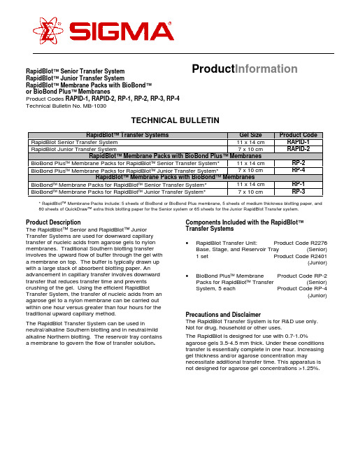
RapidBlot™ Senior Transfer System RapidBlot™ Junior Transfer SystemRapidBlot™ Membrane Packs with BioBond™or BioBond Plus™ MembranesProduct Codes RAPID-1, RAPID-2, RP-1, RP-2, RP-3, RP-4Technical Bulletin No. MB-1030TECHNICAL BULLETINRapidBlot™ Transfer Systems Gel SizeProduct CodeRapidBlot Senior Transfer System 11 x 14 cm RAPID-1RapidBlot Junior Transfer System 7 x 10 cmRAPID-2RapidBlot™ Membrane Packs with BioBond Plus™ MembranesBioBond Plus Membrane Packs for RapidBlot Senior Transfer System*11 x 14 cm RP-2BioBond Plus Membrane Packs for RapidBlot Junior Transfer System*7 x 10 cm RP-4RapidBlot™ Membrane Packs with BioBond ™ MembranesBioBond Membrane Packs for RapidBlot Senior Transfer System*11 x 14 cm RP-1BioBond Membrane Packs for RapidBlot Junior Transfer System*7 x 10 cm RP-3* RapidBlot ™ Membrane Packs include: 5 sheets of BioBond or BioBond Plus membrane, 5 sheets of medium thickness blotting paper, and 80 sheets of QuickDraw ™ extra thick blotting paper for the Senior system or 65 sheets for the Junior RapidBlot Transfer system.Product DescriptionThe RapidBlot ™ Senior and RapidBlot ™ Junior Transfer Systems are used for downward capillary transfer of nucleic acids from agarose gels to nylon membranes. Traditional Southern blotting transfer involves the upward flow of buffer through the gel with a membrane on top. The buffer is typically drawn up with a large stack of absorbent blotting paper. An advancement in capillary transfer involves downward transfer that reduces transfer time and prevents crushing of the gel. Using the efficient RapidBlotTransfer System, the transfer of nucleic acids from an agarose gel to a nylon membrane can be carried out within one hour versus greater than four hours for the traditional upward capillary method.The RapidBlot Transfer System can be used inneutral/alkaline Southern blotting and in neutral/mild alkaline Northern blotting. The reservoir tray contains a membrane to govern the flow of transfer solution .Components Included with the RapidBlot ™Transfer Systems •RapidBlot Transfer Unit: Product Code R2276Base, Stage, and Reservoir Tray (Senior)1 set Product Code R2401(Junior)• BioBond Plus Membrane Product Code RP-2Packs for RapidBlot Transfer (Senior)System, 5 each Product Code RP-4(Junior)Precautions and DisclaimerThe RapidBlot Transfer System is for R&D use only.Not for drug, household or other uses.The RapidBlot is designed for use with 0.7-1.0%agarose gels 3.5-4.5 mm thick. Under these conditions transfer is essentially complete in one hour. Increasing gel thickness and/or agarose concentration maynecessitate additional transfer time. This apparatus is not designed for agarose gel concentrations >1.25%.Product Information2Reagents that May be Required, but are Not Provided Product NameProduct Code Depurination Solution for Neutral Southern TransferN 1907Denaturation Solution for Neutral Southern TransferN 1531Neutralizing Solution for Neutral Southern TransferN 1532Transfer Solution for Neutral Southern TransferN 0907Transfer Solution for Alkaline Southern TransferA 7967Neutralizing Solution for Alkaline Southern TransferA 8092Neutral Northern Transfer SolutionN 6531Mild Alkaline Northern Transfer Solution A 8217Mild Alkaline Northern Wash Solution A 8342SSC Buffer, 20X ConcentrateS 6639Storage/StabilityThe RapidBlot Transfer unit is made of a high density polyethylene and may be stored at room temperature.The membrane, which governs the flow of the transfer solution, is stable for at least 50 transfers.Preparation Instructions1. 2X SSC for DNA solutions. Prepare 2X SSC bydiluting 50 ml of 20X SSC with 450 ml of distilled,deionized water.* Pre-wet in Transfer Solution** Sr - 12 sheets and Jr - 15 sheetsFigure 13Assembly DirectionsRefer to Figure 1a. The Stage fits at the bottom of the Base.b. Center 12 sheets for the RapidBlot Senior and15 sheets for the RapidBlot Junior of dryQuickDraw TM blotting paper on the Stage.c. Pre-wet 1 sheet of QuickDraw in theappropriate transfer solution for 10 secondsand place on top of the dry QuickDraw sheets.d.Pre-wet BioBond TM membrane in appropriatetransfer solution and place on top of the pre-wet QuickDraw.e.Center Agarose gel on the pre-wet BioBondmembrane. Smooth out any air bubbles toallow an even, efficient transfer. Note: Addingextra transfer solution to the membrane beforeplacing the gel reduces the formation ofbubbles.f. Pre-wet Medium Thickness Blotting Paper inappropriate transfer solution for 10 seconds,and place on top of the agarose gel.g. Place Reservoir Tray level on top of base andmedium thickness blotting paper. Check forcontact between the Reservoir Tray and theblotting paper.h. Fill Reservoir Tray with 170 ml of appropriatetransfer solution for a RapidBlot Senior or70 ml for a RapidBlot Junior.ProcedureA.Neutral Southern Blotting1. Prepare DNA for analysis by electrophoresis in anagarose gel containing the appropriatepercentage of agarose to resolve the bands ofinterest. For larger fragments (≥1 kb) use 0.7%agarose and for smaller fragments (0.3-3 kb), use0.8-1.0% agarose. If using BlueView Nucleic AcidStain, 10X TBE Buffer (Product Code T 9060) or10X TAE Buffer (Product Code T 8935), see thetechnical bulletin for those products for details ofelectrophoresis. Ethidium bromide staining is notnecessary for BlueView agarose gels.2. Stain gel in a solution of 0.5 µg/ml ethidiumbromide for 30 minutes at room temperature andvisualize with ultraviolet light.Note: Steps 3-5 should be performed at roomtemperature with gentle agitation.3. Depurination: If the fragments of interest arelarger than 10 kb, the DNA should be nicked bydepurination prior to transfer. To depurinate theDNA, soak the gel in several gel volumes ofDepurination Solution for 10 minutes at roomtemperature or at least until bromophenol blueindicator turns yellow.4. Denaturation: Denature the DNA by soaking thegel for 30 minutes in several gel volumes ofDenaturing Solution.5. Neutralization: Briefly rinse the gel with deionizedwater to remove any residual denaturation buffer.Neutralize by soaking the gel for 30 minutes inseveral gel volumes of Neutralizing Solution.6. Assemble the RapidBlot Transfer System (refer toAssembly Directions) using Transfer Solutionfor Neutral Southern Transfer (Product CodeN 0907).7. Allow 1 hour for the transfer.8. After transfer is complete, dismantle the reservoirtray and pour off the extra buffer. Peel off themedium thickness blotting paper and dispose.Carefully remove the gel. Carefully remove themembrane with tweezers and place on blottingpaper. Dispose of the QuickDraw sheets. Rinseeach tray with deionized water, sincecrystallization of the transfer solution on thereservoir tray could affect the future performanceof the flow-regulating membrane.9. Rinse the membrane in 2X SSC for severalminutes to remove any pieces of gel.10. Allow membrane to air dry several minutes. Topermanently affix the DNA to the membrane,bake at 80°C for 30 minutes and/or irradiate themembrane (DNA side toward the light source)with 130 mJoules of 254 nm ultraviolet light.BioBond Plus nylon membranes do not requirecrosslinking of the DNA.411. The membrane can be stored at roomtemperature between clean pieces of blottingpaper until needed. For extended use, store blotsdesiccated at 2-8°C.12. To evaluate the efficiency of transfer, the gel may berestained in a solution of 0.5 µg/ml ethidium bromide for30 minutes at room temperature and visualized withultraviolet light.B.Alkaline Southern Blotting1. Prepare DNA for analysis by electrophoresis inan agarose gel containing the appropriatepercentage of agarose to resolve the bands ofinterest. For larger fragments (≥1 kb) use 0.7%agarose and for smaller fragments (0.3-3 kb), use0.8-1.0% agarose. If using BlueView nucleic acidstain, 10X TBE Buffer (Product Code T 9060) or10X TAE Buffer (Product Code T 8935), see thetechnical bulletin for those products for details ofelectrophoresis. Ethidum bromide staining is notnecessary for BlueView agarose gels.2. Stain gel in a solution of 0.5 µg/ml ethidiumbromide for 30 minutes at room temperature andvisualize with ultraviolet light.Note: Steps 3 and 4 should be performed at roomtemperature with gentle agitation.3. Depurination: If the fragments of interest arelarger than 10 kb, the DNA should be nicked bydepurination prior to transfer. To depurinate theDNA, soak the gel in several gel volumes ofDepurination Solution for 10 minutes at roomtemperature or at least until bromophenol blueindicator turns yellow.4. Denaturation: Briefly rinse the gel with deionizedwater to remove any residual running ordepurination buffer. Denature the DNA bysoaking the gel for 30 minutes in several gelvolumes of Transfer Solution for AlkalineSouthern Transfer.5. Assemble the RapidBlot Transfer System (refer toAssembly Directions) using Transfer Solutionfor Alkaline Southern Transfer (Product CodeA7967).6.Allow 1 hour for the transfer.7.After transfer is complete, dismantle the reservoirtray and pour off the extra buffer. Peel off themedium thickness blotting paper and dispose.Carefully remove the gel. Carefully remove themembrane with tweezers and place on blottingpaper. Dispose of the QuickDraw sheets. Rinseeach tray with deionized water, sincecrystallization of the transfer solution on theReservoir Tray could affect the future performance of the flow-regulating membrane.8. Rinse the membrane in 2X SSC for severalminutes to remove any pieces of gel.9. Allow membrane to air dry several minutes. Topermanently affix the DNA to the membrane,bake at 80°C for 30 minutes and/or irradiate themembrane (DNA side toward the light source)with 130 mJoules of 254 nm ultraviolet light.BioBond Plus nylon membranes do not requirecrosslinking of the DNA.10. The membrane can be stored at roomtemperature between clean pieces of blottingpaper until needed. For extended use, storeblots desiccated at 2-8°C.11. To evaluate the efficiency of transfer, the gel maybe restained in a solution of 0.5 µg/ml ethidiumbromide for 30 minutes at room temperature andvisualized with ultraviolet light.C.Neutral Northern BlottingNote: Always use standard procedures to preventRNase contamination throughout this protocol.To make the RapidBlot unit RNase-free, wash the unit in detergent, rinse completely with deionized water and dry with ethanol. Soak the unit pieces in 3% hydrogen peroxide for 10 minutes at room temperature, then rinse completely with deionized water treated with0.1% DEPC. Do not treat RapidBlot unit directly with DEPC or autoclave. It is recommended to purchase two separate units for doing Northern and Southern transfers.51.Perform electrophoresis with RNA in formaldehydeor glyoxal/ DMSO gels according to publishedprocedures (e.g. Sambrook, et al.). The addition of formaldehyde to MOPS (Product Code M 3183)buffered gels is not required when RNA has beendenatured 10 minutes at 65°C in RNA SampleLoading Buffer (Product Code R 4268) prior toloading.2.For RNA gels containing formaldehyde, wash thegel twice for 15 minutes in several gel volumes ofRNase free water to remove residualformaldehyde. Glyoxal/DMSO gels do not requireany pretreatment.3. Stain gel in a solution of 0.5 µg/ml ethidiumbromide for 30 minutes at room temperature andvisualize with ultraviolet light.4. Assemble the RapidBlot Transfer System (refer toAssembly Directions) using Neutral NorthernTransfer Solution (Product Code N 6531).5. Allow 1 hour for the transfer.6. After transfer is complete, dismantle the reservoirtray and pour off the extra buffer. Peel off anddispose the medium thickness blotting paper.Carefully remove the gel. Carefully remove themembrane with tweezers and place on blottingpaper. Dispose of the QuickDraw sheets. Rinseeach tray with deionized water, sincecrystallization of the transfer solution on thereservoir tray could affect the future performanceof the flow-regulating membrane.7. Rinse the membrane in 2X SSC for severalminutes to remove any pieces of gel.8. Allow membrane to air dry several minutes. Topermanently affix the RNA to the membrane,bake at 80°C for 30 minutes and/or irradiate themembrane (RNA side toward the light source)with 130 mJoules of 254 nm ultraviolet light.BioBond Plus nylon membranes do not requirecrosslinking of the RNA.9. The membrane can be stored at roomtemperature between clean pieces of blottingpaper until needed. For extended use, storeblots desiccated at 2-8°C.10. To evaluate the transfer efficiency, the gel maybe restained in a solution of 0.5 µg/ml ethidiumbromide for 30 minutes at room temperature andvisualized with ultraviolet light.d Alkaline Northern BlottingNote: Always use standard procedures to prevent RNase contamination throughout this protocol. See Section C for detailed instructions on the preparationof the RapidBlot unit.1. Perform electrophoresis with RNA informaldehyde or glyoxal/DMSO gels according topublished procedures (e.g. Sambrook, et al.).The addition of formaldehyde to MOPS (ProductCode M 3183) buffered gels is not required whenRNA has been denatured 10 minutes at 65°C inRNA Sample Loading Buffer(Product Code R4268) prior to loading.2. For RNA gels containing formaldehyde, wash thegel twice for 15 minutes in several gel volumes ofRNase free water to remove residualformaldehyde. Glyoxal/DMSO gels do not require any pretreatment.3. Stain gel in a solution of 0.5 µg/ml ethidiumbromide for 30 minutes at room temperature andvisualize with ultraviolet light.4. Assemble the RapidBlot Transfer System (refer toAssembly Directions) using Mild AlkalineNorthern Transfer Solution (Product CodeA8217).5. Allow 1 hour for the transfer.6. After transfer is complete, dismantle thereservoir tray and pour off the extra buffer. Peeloff the medium thickness blotting paper anddispose. Carefully remove the gel. Carefullyremove the membrane with tweezers and placeon blotting paper. Dispose of the QuickDrawsheets. Rinse each tray with deionized water,since crystallization of the transfer solution onthe reservoir tray could affect the futureperformance of the flow-regulating membrane. 7. Rinse the membrane in Mild Alkaline NorthernWash Solution for several minutes to remove anypieces of gel.68.Allow membrane to air dry several minutes. To permanently affix the RNA to the membrane, bake at 80°C for 30 minutes and/or irradiate themembrane (RNA side toward the light source) with 130 mJoules of 254 nm ultraviolet light. BioBond Plus nylon membranes do not require crosslinking of the RNA.9.The membrane can be stored at roomtemperature between clean pieces of blotting paper until needed. For extended use, store blots desiccated at 2-8°C.10. To evaluate the transfer efficiency, the gel maybe restained in a solution of 0.5 µg/ml ethidium bromide for 30 minutes at room temperature and visualized with ultraviolet light.Troubleshooting Guide Problem CauseSolutionDNA fragments are too large Depurinate gel before transfer or increase the depurination time.Gel is too thick (over 4.5 mm)Use a thinner gel or increase the transfer time.Agarose gel concentration is too high Use a lower concentration or increase the transfer time.This apparatus is not designed for agarose gel concentrations >1.25%.Stack is not contacting reservoir tray Add more height to the bottom of the QuickDraw stack.Crushing of the gelReduce the height of the QuickDraw stack by removing single sheets of QuickDraw until the stack is the correct height.Incomplete transferNot enough transfer solution Add more solution to the reservoir tray.Uneven transfer Reservoir tray not levelMake sure the reservoir tray is level during transfer.Non-specific binding of probe to target nucleic acidsAdd sheared, denatured salmon testes DNA (Product Code D 7656) to a final concentration of 100 µg/ml in prehybridization and hybridization solutionsHighbackgroundWash conditions are not sufficiently stringentAdd an ultra-high stringency wash step (0.1X SSC,0.1% SDS). Wash for 20 minutes at hybridization temperature. Increase the temperature of the hybridization and/or washes.Probe was not labeled efficientlyCheck that the specific activity of radiolabeled probes is>5 x 10⁸cpm/µg. For non-radioactive probes, check the incorporation of hapten by spotting and detecting serial dilutions of probe in direct comparison to aknown standard. If probes are not labeled well enough,remake and confirm adequate incorporation rates.Target nucleic acids are not present,have been degraded, or are too low for detectionRun agarose gel electrophoresis to confirm nucleic acids are not degraded. Load more target nucleic acids for blotting. For Northern blots, up to 30 µg of total RNA can be loaded per laneWeak or absent signalNon-radioactive detection system is not working properlyConfirm the enzyme/antibody conjugate is functioning properly by spotting and detecting the labeled probe on nylon membrane. If the enzyme/antibody conjugate is functional, check the chemiluminescent substrate by spotting the enzyme/antibody conjugate on a membrane and detecting with the substrate in question.7General ReferencesChomczynski, P., One-hour downward alkaline capillary transfer for blotting of DNA and RNA. Anal. Biochem., 201, 134-139 (1992)Chomczynski, P. and Mackey, K., One-hour downward capillary blotting of RNA at neutral pH. Anal. Biochem., 221, 303-305 (1994)Lichtenstein, A.V., et al., A procedure for DNA and RNA transfer to membrane filters avoiding weight-induced gel flattening. Anal. Biochem., 191, 187-191 (1990)Meinkoth, J. and Wahl, G., Hybridization of nucleic acids immobilized on solid supports. Anal. Biochem., 138, 267 (1984)Southern, E.M., Detection of specific sequences among DNA fragments separated by gel electrophoresis. J. Mol.Biol., 98, 503-517 (1975)Sambrook, J, et al. Molecular Cloning: A Laboratory Manual, Third Edition, Cold Spring Harbor Laboratory Press, New York (2000) (Product Code M 8265)Related ProductsProduct Name Product CodeQuickDraw™ Extra Thick Blotting Paper P 7796, P 6803, P 7921Medium Thickness Blotting Paper P 6664DNA gel loading solution G 7654RNA sample loading buffer R 426810X TBE Buffer T 4415MOPS-EDTA-sodium acetate buffer M 5755T 9060BlueView Nucleic Acid Stain, 10X TBEBufferT8935BlueView Nucleic Acid Stain, 10X TAEBufferSouthern Breeze™ Blotting Kits SBRZ-1A, SBRZ-1B, SBRZ-2A, SBRZ-2BAlkaline Southern Breeze™ Blotting Kits ASBRZ-1A, ASBRZ-1B, ASBRZ-2A,ASBRZ-2BNorthern Breeze™ Blotting Kits NBRZ-1A, NBRZ-1B, NBRZ-2A,NBRZ-2BPerfectHyb Plus™ Hybridization Buffer H 7033CDP-Star™ Universal Detection Kit U-ALKN 8530, N 9155, N 8405, N 9280All-in-One™ Nick Translation LabelingMixesAll-in-One Random Prime Labeling Mixes R 7522, R 9647, R 7022, R 9522BioBond™ Plus Nylon Membranes N 5281, N 5781, N 5406, N 5531, N 5656BioBond™ Nylon Membranes N 1406, N 4031, N 3656, N 3781, N 3906UniScript™ Transcription Kits US-T3, US-T7, US-SP6Precast Agarose Gels P 5472, P 5722, P 6222, P 5972E 1385Ethidium Bromide, aqueous solution,500 µg/mlJM 5/01Sigma brand products are sold through Sigma-Aldrich, Inc.Sigma-Aldrich, Inc. warrants that its products conform to the information contained in this and other Sigma-Aldrich publications.Purchaser must determine the suitability of the product(s) for their particular use. Additional terms and conditions may apply.Please see reverse side of the invoice or packing slip.。
BEA 10BOX45SQSM 产品说明书

MS41 75.5996.03 MS41 20210421 Página 1 de 4Las especificaciones están sujetas a cambios sin previo aviso.Todos los valores se han medido bajo condiciones específicas.Visite el sitio web para verlos idiomas disponibles paraeste documento.Actuador de acero inoxidable, sin contacto, con rangoajustable y tiempo de espera de relé.MÓDULO SIMPLEESPAÑOL4,5” (CUADRADO)1. Requiere soporte adaptador.2. No provisto por BEA.6” (REDONDO)1Página 2 de 4 75.5996.03 MS41 202104219Al conectar varios dispositivos juntos para crear la configuración de un sistema, es recomendable verificar que cada uno de ellos funcione en forma independiente. Esta precaución facilitará la solución de problemas en caso de discrepancia. 9Antes de instalar cualquier equipo en un circuito nuevo o actual, verifique la tensión y la estabilidad de la línea. Siempre recuerde desconectar la alimentación eléctrica antes de iniciar el cableado del circuito. 9No coloque el sensor en el rango de apertura de la puerta, donde este detectaría el movimiento propio de esta ubicación. 9No coloque ningún objeto móvil delante del sensor.EXTRACCIÓN DE LA PLACA FRONTALPara separar la placa frontal del cubo, introduzca un destornillador para tornillos de cabeza plana en uno de los accesorios de fijación a presión y gire hasta aflojar la placa (consulte lasiguiente imagen). Repita el procedimiento en el accesorio ubicado en ese mismo lado, arriba o abajo.Puede separar el cubo de la placa desde la parte superior o inferior. Solo se deben aflojar dos accesorios de fijación.PRECAUCIONESDesconecte toda la alimentación eléctrica del cabezal antes de intentar ningún procedimiento de cableado. Mantenga un entorno limpio y seguro al trabajar en áreas públicas.En todo momento, esté atento al tránsito de peatones en torno al área de la puerta.Al realizar pruebas que puedan derivar en reacciones inesperadas de la puerta, siempre interrumpa el tránsito peatonal deesa entrada. ESD (descarga electrostática): Las placas de circuitos son vulnerables a los daños producidos por las descargas electrostáticas.Antes de manipular cualquier placa, asegúrese de disipar la descarga electrostática de su cuerpo. Antes de accionar el mecanismo, verifique siempre la disposición del cableado para asegurarse de que las piezas móviles dela puerta no alcancen ningún cable y puedan dañar el equipo. Una vez finalizada la instalación, verifique el cumplimiento de todas las normas de seguridad pertinentes (p. ej., ANSIA156.10). NO intente realizar ninguna reparación interna de los componentes. Todas las reparaciones o reemplazos de componentesdeben ser efectuados por BEA, Inc. La reparación o desmontaje no autorizados:1. pueden comprometer la integridad física y exponer a cualquier persona al riesgo de una descarga eléctrica; y2. pueden impedir el funcionamiento seguro y confiable del producto, provocando la anulación de la garantía.2375.5996.03 MS41 20210421Página 3 de 4CABLEADO (cont.)INSTALACIÓNPueden realizarse seis ajustes al sensor:Color del LED+lógica: El banco DIP 1 determina elcolor del LED (consulte la tabla)Interruptor de modo de salida: determina el modo alterno o temporizador↑ = Alterno (la detección activa el relé, y este espera hasta que una segunda detección lodesactiva [recomendado para aplicaciones de conmutación]).↓ = Temporizador (la detección activa el relé durante 0,5 a 30 segundos; el relé esperará hastaque se produzca la detección).Actividad del LED (durante su iluminación):↑ = animado (movimiento en torno a la trayectoria)↓= estándar (encendido, estático)Sonido de chicharra (durante la detección):↓ = encendido ↓ = apagadoPotenciómetro de tiempo de espera: ajuste el tiempo de espera del relé de 0,5 a 30 segundos (paraaumentar, gire en sentido horario).Potenciómetro de sensibilidad: ajuste el campo de detección de 4 a 24 pulgadas (10,16 a 61 cm) (paraaumentar, gire en sentido horario).DIP1DIP2DIP3DETEC-CIÓNSIN DETECCIÓN↓↓↓azul apagado ↓↓↓apagado azul ↓↓↓azul azul ↓↓↓verde apagado ↓↓↓apagado verde ↓↓↓verde verde ↓↓↓azul verde ↓↓↓verdeazulAPLICACIÓN DE READAPTACIÓNEs posible actualizar las placas de empuje conectadas usando el receptor (10RD900) y transmisor (10TD900TR) de readaptación sin contacto 900 MHZ:1. Ubique los 2 cables existentes, previamente usados para la placa de empuje mecánica cableada, y conéctelos a los terminales del MS41 marcados con la calificación de 12 – 24 V CA/V CC.2. Conecte los cables eléctricos del transmisor (rojo y negro) con los dos cables de alimentación del MS41.3. Conecte el cable blanco del transmisor con el terminal COM, y el cable verde con el terminal N.A.4. En el control de la puerta, mueva los 2 cables del circuito de activación de la placa de empuje a la alimentación eléctrica (para obtener información sobre la alimentación eléctrica, consulte las Especificaciones técnicas).5. Conecte la salida del receptor al circuito de activación del control de la puerta y a los cables eléctricos indicados en el paso 3 anterior.4Página 4 de 475.5996.03 MS41 20210421Soporte técnico & Servicio al cliente: 1-800-523-2462Preguntastécnicasgenerales:******************************|Documentostécnicos:La puerta no se abre al pasar la mano delante del sensor.El sensor permanece en modo de detección.La puerta permanece abierta después de la detección o activación.©B E A | I n s t r u c c i o n e s o r i g i n a l e s | C O N S E R V A R P A R A R E F E R E N C I A F U T U R A - D I S E ÑA D O P A R A I M P R E S I ÓN E N C O L OREste dispositivo cumple con el apartado 15 de las normas de la FCC y con la norma RSS-210 de Industry Canada.Su funcionamiento está sujeto a las siguientes dos condiciones:*este dispositivo no puede causar interferencias perjudiciales, y*este dispositivo debe aceptar cualquier interferencia que reciba, incluso aquellas que puedan causar un funcionamiento inadecuado.este equipo ha sido probado y cumple con los límites establecidos para un dispositivo digital de Clase B de acuerdo con el apartado 15 de la normativa FCC. Estos límites están diseñados para proporcionar una protección razonable contra cualquier interferencia perjudicial en una instalación doméstica. Este equipo genera, utiliza y puede emitir energía con frecuencias de radio y, si no se instala y utiliza según las instrucciones, puede causar interferencias perjudiciales a las radiocomunicaciones. Sin embargo, esto no garantiza que no se producirán interferencias en una instalación en particular. Si este equipo causa interferencias perjudiciales a la recepción de las señales de radio o televisión, lo cual se puede determinar al encender y apagar el equipo, se recomienda al usuario que intente corregir la interferencia siguiendo alguna/s de las siguientes medidas:*Cambie la orientación o la ubicación de la antena receptora.*Aumente la separación entre el equipo y el receptor.*Conecte el equipo a una salida de un circuito que no esté usando el receptor.*Consulte al fabricante o a un técnico especializado en radio y TV para obtener ayuda.ADVERTENCIA: SI SE REALIZAN CAMBIOS O MODIFICACIONES A ESTE EQUIPO SIN LA APROBACIÓN EXPRESA DE BEA INC., PODRÍA ANULARSE LA AUTORIZACIÓN DE LA FCC PARA SU UTILIZACIÓN.INSTALACIÓN1. Instale una caja eléctrica.Si utiliza una caja eléctrica de metal, verifique que el sensor y todos sus cables asociados no entren en contacto con la caja para evitar un cortocircuito.2. Ajuste el cubo MS41 con la placa frontal.S i desea alcanzar un grado de protección IP65, apliquesilicona entre el cubo MS41 y la placa frontal antes de instalar el dispositivo en la caja eléctrica.3. Asegure la placa frontal en la caja eléctrica usando los tornillos provistos.caja eléctrica (metal/plástico )MS41MS41。
鹰扣LP10B LP25B逻辑探头用户手册说明书

Certifications and Precautions This instrument is EMC/EMI certified. All inputs are protected against continuous overload conditions up to the limits of each function’s stated input protection (see specifications). Never exceed these limits or the ratings marked on the instrument itself. Always inspect your Logic Probe, test leads and accessories for signs of damage or abnormality before every use. If an abnormal condition exists (broken or damaged test leads, cracked case, display not reading, etc.), do not use. Never ground yourself when taking measurements. Do not touch exposed metal pipes, outlets, fixtures, etc., which might be at ground potential. Keep your body isolated from ground and never touch exposed wiring, connections, test probe tips, or any live circuit conductors. Do not operate instrument in an explosive atmosphere (flammable gases, fumes, vapor, dust.) Do not use this or any piece of test equipment without proper training.
B-10模型SHS-R和SHS-LR产品说明书

B-10Models SHS-R and SHS-LR(*1) See contamination protection accessory on A-368. (*2) See A-113. (*3) See A-119. (*4) See A-59.Note)This model number indicates that a single-rail unit constitutes one set. (i.e., required number of sets when 2 rails areused in parallel is 2 at a minimum.)Those models equipped with QZ Lubricator cannot have a grease nipple.Model No.Outer dimensions LM block dimensionsPilot hole for side nippleHeight Width LengthGrease nippleMW L B C S l L 1T K N Ee 0f 0D 0SHS 15R 283464.42626M4 548 5.9259.55.5PB1021B 483SHS 25R SHS 25LR 404892109353550M6 87188834.211.512B-M6F 69.53SHS 30R SHS 30LR 4560106131404060M8 10801058381112B-M6F 5.595.2SHS 35R SHS 35LR 5570122152505072M8 129312314.747.51512B-M6F 6.512.5 5.2SHS 45R SHS 45LR 7086140174606080M10 1710614014.961.120.516B-PT1/8818 5.2SHS 55R SHS 55LR80100171213757595M12 1813117319.467.32116B-PT1/81018 5.2Symbol forNo. of rails used on the same plane (*4)Symbol for LM rail jointed use LM rail length (in mm)Contamination protection accessory symbol (*1)With QZ LubricatorAccuracy symbol (*3)Normal grade (No Symbol)/High accuracy grade (H)Precision grade (P)/Super precision grade (SP)Ultra precision grade (UP)Radial clearance symbol (*2)Normal (No symbol)Light preload (C1)Medium preload (C0)No. of LM blocksused on the same railType of LM blockModelnumberSHS45 LR 2 QZ KKHH C0 +1200L P T -LM GuideTHK will mount grease nipples per your request. Therefore, do not use the side nipple pilot holes for purposes otherthan mounting a grease nipple.The maximum length under “Length” indicates the standard maximum length of an LM rail. (See B-12.)Static permissible moment: 1 block: static permissible moment value with 1 LM blockDouble blocks: static permissible moment value with 2 blocks closely contacting with each otherB-11Description of Each Option A-351 Dimensions B-223。
杰克雷锐锐10BL60和10BL120电机说明书
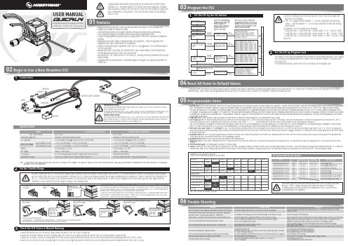
QUICRUN 10BL60 SENSOREDWhen using sensored brushless motor, please connect the “SENSOR” port of the ESC and the the “SENSOR”For sensored brushless motor, the #A, #B, #C wires of the ESC MUST be connected with the motor wire #A, #B,SwitchElectronic Speed ControllerReceiverBlue (A)Yellow (B)Orange (C)CapacitorSensor wire01Begin to Use a New Brushless ESC03Program the ESCSet the ESC by the SET button1Set the ESC by Program Card2Set the Throttle Range2The Program Card is optional equipment which needs to be purchased separately. It has 3 digital LEDs to display the programmable items’ number and the options’ number. It is portable and very easy to use.(For detailed information, please refer to the user manual of the program card).04Reset All Items to Default ValuesAt any time when the throttle is located at neutral position (except in the throttle calibration or parameters program process), press and hold the “SET” key for over 3 seconds, the red LED and green LED will blink simultaneously , which means each programmable item has be reset to its default value. It needs to be restarted to complete the whole process.USER MANUAL10BL60 / 10BL120 SensoredBrushless Electronic Speed ControllerNote: “T” indicates the limit value of motor turns when the ESC timing is set to 0 degree. The larger the timing, the more turns the motor needs. Please pay close attention to temperatures of the motor and the ESC to avoid any damage to these two equipments.d) When the car reverses, the Red LED solidly lights; the Green LED also lights up when the throttle stick is at the end position and the maximum reverse force is set to 100%.05Programmable Items06Trouble Shooting1. Running Mode: With “Forward with Brake” mode, the car can go forward and brake, but cannot go backward, this mode is suitable for competition; “Forward / Reverse with Brake” mode has reverse running function, which is suitable for daily training. Note: “Forward/Reverse with Brake” mode uses “Double-click” method to make the car go backward. When you move the throttle stick from forward zone to backward zone for the first time (The 1st “click”), the ESC begins to brake the motor, the motor slows down but it is still running, not completely stopped, so the backward action is NOT happened immediately. When the throttle stick is moved to the backward zone again (The 2nd “click”), if the motor speed is slowed down to zero (i.e. stopped), the backward action will happen. The “Double-Click” method can prevent mistakenly reversing action when the brake function is frequently used in steering. By the way, in the process of braking or reversing, if the throttle stick is moved to forward zone, the motor will run forward at once. “Forward/Reverse” mode uses “single-click” method to make the car reverse. When moving the throttle stick from neutral zone to backward zone, the vehicle reverses immediately, so this mode is usually used by rock crawler.2. Drag Brake Force: Set the amount of drag brake applied at neutral throttle to simulate the slight braking effect of a brushed motor while coasting.3. Low Voltage Cut-Off: The function mainly prevents the Lipo battery from over discharging. The ESC detects the battery voltage at any time, if the voltage is lower than the threshold for 2 seconds, the output power will be reduced 70%, after 10 seconds the output power will be completely shut off and the red LED flashes in such a way: “☆-, ☆-, ☆-”. Please stop your car at the track side as soon as possible to avoid obstructing other racing cars.Note: For NiMH battery, if the voltage of the whole NiMH battery pack is higher than 9.0V, it will be considered as a 3 cells Lipo battery pack; If it is lower than 9.0V, it will be considered as a 2 cells Lipo battery pack. For example, if a NiMH battery pack is 8.0V, and the threshold is set to 2.6V/Cell, so it will be considered as a 2 cells Lipo battery pack, and the low-voltage cut-off threshold for this NiMH battery pack is 2.6x2=5.2V.4. Start Mode (Also called “Punch” or “Acceleration”): Level 1 has very soft start acceleration, while level 9 has very quick start acceleration. From Level 1 to Level 9, the start force is increasing. If you choose “Level 7” to “Level 9”, you should use good quality battery with powerful discharge ability, otherwise you cannot get the burst start effect as you want. If the motor cannot run smoothly (the motor is cogging), sometimes it is caused by the weak discharge ability, please use a better battery or increase the gear ratio.5. Maximum Brake Force: The ESC provides proportional brake function. The brake force is related to the position of the throttle stick. Maximum brake force refers to the force when the throttle stick is located at the end point of the backward zone. A very large brake force can shorten the brake time, but it may damage the gears.6. Maximum Reverse Force: Sets how much power will be applied in the reverse direction.7. Initial Brake Force: It is also called “minimum brake force”, which refers to the force when the throttle stick is located at the initial position of the backward zone. The default value is equal to the drag brake force, so the brake action can be very smoothly.8. Throttle Neutral Range: This setting adjusts the width of the neutral range.9. Timing: This function can be used to fine-tune the output power of the motor, the bigger the timing, the faster the motor runs or the larger output power of the motor. As the Boost Timing technology has been introduced into this ESC, so under the sensored mode, adjust the ESC timing can greatly increase the motor speed. Therefore, please remember to enlarge the gear ratio of the chassis and carefully check temperatures of the motor and the ESC after increasing the timing.20170719。
Verathon BladderScan i10 产品说明书

TRUSTED ACCURACY MEETS TESTED DURABILITYTRUSTED ACCURACY MEETSTESTED DURABILITYTRUSTED ACCURACY FOR EVERY USERPowered by ImageSense TM, Verathon’s groundbreakingartificial intelligence technology, BladderScan i10TM harnessesreal-world data to consistently detect and define bladderlocation, size and shape across all pediatric and adult patienttypes and anatomies.± 7.5% on volumes greater than 100 mL*± 7.5 mL on volumes less than 100 mLACCELERATED WORKFLOWImageSense, combined with V MODE® probetechnology, automatically measures the bladdervolume within seconds.• Large 10.1” (25.6 cm) optically bondedtouchscreen reduces glare• Interface uses intuitive graphics, automaticbladder location detection and BladderTraq TMcontour tracking to guide the user throughevery step• Simple charting tool easily transfers exam resultsto any electronic healthcare record systemOptimized for roaming through hectic hospitalcorridors, BladderScan i10 pairs with a quietglide workstation.• Single-handed probe docking keeps usersfocused on the patient – not on managingthe equipment• 360-degree handle enables easy positioning• With both onboard charging and user-swappable battery, the system is always readywhenever and wherever you need it*Accuracy specifications assume BladderScan i10 is being used in accordance with stated instructions, scanning a tissue-equivalent phantom.TOUGH AND READY DEPENDABILITY BladderScan i10TM is designed and built for continuous operation in taxing hospital environments.• Durable construction consisting of medical grade materials, metal gears and industrial- strength locking cables ensure reliable operation and high service availability • No routine calibration is needed, even if you swap probes• CaliScan TM probe diagnostics confirm probe function in the event of a drop BladderScan i10 is designed to meet the new realities of infection control.• Custom-blended medical grade materials withstand fast-kill disinfectants • Rugged, fully-sealed IPX4 probe and drip resistant IPX2 console ensure your precision electronics are protectedPrinter (optional)360-degree handle for easy transport and positioning• Aluminum column • Cable managementand protection• No-slip track mounting• Large display with intuitive graphics • Tilt and height adjustable • VESA quick mounting • Drip resistant IPX2 sealingUser-swappable battery pack• Rugged 3D probe• Fully-sealed IPX4 protection • Light and flexible cable • Single-handed dockingGenerous storage space for suppliesAC adapter for onboard chargingLow-profile base with quiet glide wheelsOPTIMIZED UPTIME WITH PERSONALIZED CUSTOMER EXPERIENCEYour customer experience is our top priority. Here are a few examples of how we’re making your life easier:• No routine calibration needed• Onboard diagnostics to support your preventative maintenance program • Complimentary software upgrades allow you to update your instrument over time • Quick transfer of configuration settings:Clone preferred device settings across the fleet • Device configuration lockdown functionality ensures compliance with individual hospital regulations and best practices • Service Partner ProgramsCERTAINTY IN YOUR INVESTMENTYou can keep out-of-pocket costs to a minimumover the life of your device, thanks to a comprehensive factory warranty and exceptional plimentary on-site training, software updates and fleet management services optimize usage. Technical support and customer service teams are on call to augment your on-site support.Verathon ® enhances the value of BladderScan i10TM with exceptional support, so you can have peace of mind knowing your investment is working every day to improve patient care.COMPREHENSIVE 5-YEAR WARRANTY• 5-Year Factory Warranty covers all damage and failures associated with the probe and console • Same-day loaner shipping when your order is processed by 2:00 PM PST • “One call does it all”. If you need assistance, our experienced US-based customer service and full-line technical support teams are ready to help.• Typical service turnaround within 5-days from receipt of instrumentVerathon Inc.20001 North Creek Parkway Bothell, WA 98011 USATel: +1 800 331 2313(USA & Canada only)Tel: +1 425 867 1348Fax: +1 425 883 2896Verathon Medical (Europe) B.V.Willem Fenengastraat 131096 BL Amsterdam The NetherlandsTel: +31 (0) 20 210 30 91Fax: +31 (0) 20 210 30 92Verathon Medical (Australia) Pty Limited Unit 9, 39 Herbert Street St Leonards NSW 2065 AustraliaTel: 1800 613 603 (Within Australia)Fax: 1800 657 970Tel: +61 2 9431 2000 (International)Fax: +61 2 9475 1201BladderScan, the BladderScan symbol, BladderScan i10, BladderTraq, CaliScan, ImageSense, V MODE , Verathon, and the Verathon Torch symbol are trademarks of Verathon Inc. © 2021 Verathon Inc. Not all Verathon Inc. products and services shown are available for commercial sale in all countries.0900-5080 Rev-00。
海伯利摄影产品海伯利尔莫·超104和超106电影相机说明书

9019 Super 106 (black model) w/grip, softcase shoulder
strap, bracket, lens hood _____ _________________
$269.95
58
Item 20·300
HONEYWELL PHOTOGRAPHIC PRODUCTS
176.50
9003 Grip ___ _
7.95
9006 Remote control
4.50
9007 S~oulder strap _____ _ 9008 Fader _____________ _
2.50 34.95
9001 Hard leather case for camera with grip _________
3. Fine Honeywell Elmo optics with a crisp 4:1 (8.5mm to 34mm) f/1.8 power zoom lens. The zoom can also be operated manually.
4. Pushbutton electric long-run film drive - 18 & 24 fps. Also single-frame operation for special effects.
THE SUPER 106 is a superbly crafted camera with all the features of the Super 104, but with a sharp 6.25:1 (8mm to 50mm) fl1.8 power zoom lens! It's the most compact and quietest camera on the market with a zoom lens of this range.
- 1、下载文档前请自行甄别文档内容的完整性,平台不提供额外的编辑、内容补充、找答案等附加服务。
- 2、"仅部分预览"的文档,不可在线预览部分如存在完整性等问题,可反馈申请退款(可完整预览的文档不适用该条件!)。
- 3、如文档侵犯您的权益,请联系客服反馈,我们会尽快为您处理(人工客服工作时间:9:00-18:30)。
上海安越电气工程技术有限公司 Anyue Electric Engineering Technology Co., Ltd
IM BJX-110/220-06C Ver. 6.2 Mar.06.2010
BJX-110/220 系列变压器中性点棒间隙操作手册
上海安越电气工程技术有限公司 Anyue Electric Engineering Technology Co., Ltd
IM BJX-110/220-06C Version 6.2 Feb.2010
BJX-110/220 系列变压器中性点棒间隙操作手册
感谢您使用 BJX 系列产品! 此操作手册为供货范围的一部分,为保证对设备进行正确的操作和使用,在设备安装 前,请仔细阅读本操作手册!同时,本手册也为安装、操作、维修等相关人员提供技 术指南。 此操作手册在未经上海安越电气工程技术有限公司书面许可的情况下,不得用于其他 目的的商业行为。
Instruction Manual
IM BJX-110/220-06C
BJX-110/220 系列变压器中性点 棒间隙操作手册
Anyue Electric Engineering Technology(Shanghai)Co., Ltd.
中国上海市杨浦区邯郸路 100 号
Room 120, Building 54-Yi
IM BJX-110/220-06C Ver. 6.2 Mar.06.2010
BJX-110/220 系列变压器中性点棒间隙操作手册
1
目录 1. 产品概述......................................................................................................................................................... 1
4.7.1 电磁式电流互感器 ........................................................................................................................ 5 4.7.2 电子式电流互感器 ........................................................................................................................ 7 4.8 外形尺寸 .............................................................................................................................................. 9 4.8.1 型号:BJX-110-N ........................................................................................................................ 9 4.8.2 型号:BJX-110-W...................................................................................................................... 10 4.8.3 型号:BJX-110-M...................................................................................................................... 11 4.8.4 型号:BJX-220-N ...................................................................................................................... 12 4.8.5 型号:BJX-220-W ..................................................................................................................... 13 4.8.6 型号:BJX-220-M...................................................................................................................... 14 4.8.7 LRB 系列变压器中性点隔离开关专用接地电流互感器 ......................................................... 15 4.9 间隙外形尺寸及重量 ........................................................................................................................ 16 4.10 型号及代码 ........................................................................................................................................ 16 5. 安装要求....................................................................................................................................................... 17 5.1 装卸注意事项 .................................................................................................................................... 17 5.1.1 运输要求...................................................................................................................................... 17 5.1.2 装卸要求...................................................................................................................................... 17 5.1.3 开箱前检查.................................................................................................................................. 17 5.2 设备开箱 ............................................................................................................................................ 17 5.3 现场安装要求 .................................................................................................................................... 18 5.3.1 安装方式...................................................................................................................................... 18
1.1 产品设计依据 ...................................................................................................................................... 1 1.2 产品适用范围 ...................................................................................................................................... 1 1.3 放电电流测量 ...................................................................................................................................... 1 1.4 质量管理体系 ...................................................................................................................................... 1 1.5 引用技术标准 ...................................................................................................................................... 1 2. 功能描述......................................................................................................................................................... 2 2.1 间隙放电保护功能 .............................................................................................................................. 2 2.2 间隙距离调整功能 .............................................................................................................................. 2 2.3 放电电流测量功能 .............................................................................................................................. 2 2.4 快速固定安装功能 .............................................................................................................................. 2 3. 外形结构......................................................................................................................................................... 3 3.1 部件名称 .............................................................................................................................................. 3 3.2 产品说明 .............................................................................................................................................. 3 4. 技术性能......................................................................................................................................................... 4 4.1 系统额定电压 ...................................................................................................................................... 4 4.2 间隙电极曲率半径 .............................................................................................................................. 4 4.3 间隙距离可调范围 .............................................................................................................................. 4 4.4 工频放电电压 ...................................................................................................................................... 4 4.5 放电频率特性(伏-秒特性)............................................................................................................. 4 4.6 高压支柱绝缘子 .................................................................................................................................. 4 4.7 电流互感器 .......................................................................................................................................... 4