PM-351I使用手册
351-1操作说明
SEL-351方向过电流继电器重合闸继电器故障定位器使用手册1998年5月8日SCHWEITZER ENGINEERING LABORATORIES, INC.2350 NE HOPKINS COURTPULLMAN, WA USA 99163-5603TEL:(509)332-1890 FAX:(509)334-8280本中文翻译本手册是在英文版的SEL-321-5使用手册(1998年5月29日)基础上翻译而成,作为中国用户的使用参考。
使用手册含义的准确性以SEL公司出版的英文版使用手册为准。
本使用手册涉及的所有软件版本、系统接线图、继电器命令控制字和继电器报文均受到美国版权法律和国际间协议条款的保护。
保留所有的版权。
本手册涉及的软件不可以被复制、改变、分离或反演设计,而且也不可以向第三者提供。
SELogic是SEL公司的注册商标,不准翻录。
目录第一部分:简介和特性................................................................................ 1-1 SEL-351继电器型号 ....................................................................................................................... 1-1使用手册章节概述........................................................................................................................... 1-2 应用................................................................................................................................................... 1-4 硬件连接特性................................................................................................................................... 1-5 通讯连接........................................................................................................................................... 1-8 基本特性........................................................................................................................................... 1-9 信号处理参数.......................................................................................................................... 1-11 保护元件整定范围和精度...................................................................................................... 1-11 瞬时/定时限过流元件...................................................................................................... 1-11 反时限过流元件............................................................................................................... 1-11 低电压(27)/过电压(59)元件 ............................................................................................ 1-12 同期检测元件................................................................................................................... 1-12 低频/高频元件......................................................................................................................... 1-12 计时器...................................................................................................................................... 1-12 变电站电源电压监视.............................................................................................................. 1-12 表计精度.................................................................................................................................. 1-12 功率元件精度.......................................................................................................................... 1-13表格表格1.1:SEL-351继电器型号 ..................................................................................................... 1-1图形图1.1:SEL-351继电器在电力系统中的应用 ............................................................................. 1-4 图1.2:SEL-351继电器输入、输出和通讯串口(型号0351xM)........................................... 1-5 图1.3:SEL-351继电器的输入、输出和通讯串口(型号0351x0,0351x1和0351xJ;型号0351x1和0351xJ具有附加I/O板-见下图)................................................................................ 1-6 图1.4:SEL-351继电器附加I/O板(型号0351x1和0351xJ;主板显示在上图)................ 1-7 图1.5:SEL-351继电器通讯连接举例 ......................................................................................... 1-8第一部分:简介和特性本部分包括下面的SEL-351继电器概述:SEL-351继电器型号使用手册章节应用硬件连接特性通讯连接基本特性SEL-351继电器型号本使用手册包括下面的SEL-351继电器型号:表格1.1:SEL-351继电器型号型号来自SEL-351继电器定货信息清单。
浙大中控DCS系统
2. 浙大中控DCS硬件介绍
2.3系统卡件介绍 2.3.1主控卡FW243X 主控卡FW243X卡件地址设置规范 主控制卡FW243X的地址范围为2~127(AdvanTrol-Pro2.5软件支 持2~63) 当卡件冗余时:地址设为I,I+1,I为偶数 当单卡工作时:地址设为I,I为偶数;2≦I ≦127 SW1拨码开关一共有8为,采用二进制,分别用S1~S8表示,S1为 高位,S8为低位,开关拨成ON时,代表二进制码为1,拨成 OFF时,表示该位为0.目前SW1保留,默认为OFF。
2. 浙大中控DCS硬件介绍
2.3系统卡件介绍
2.3.1主控卡FW243X LED指示灯说明
2. 浙大中控DCS硬件介绍
2.3系统卡件介绍 2.3.1主控卡FW243X LED指示灯说明 FALL灯是故障指示灯,当主控卡故障时,FALL灯会报警亮红灯, 系统正常时,FALL灯熄灭。 RUN与STDBY分别是卡件运行指示和准备就绪指示,当备卡在拷贝 工作卡的信息时,两块主控卡的RUN与STDBY都会不停地交替闪烁。 WORK灯是工作/备用指示灯,工作的主控制卡的WORK灯亮绿灯,备 用的主控制卡的WORK指示灯是熄灭的,通过WORK的ቤተ መጻሕፍቲ ባይዱ示灯的指示, 我们可以直接判断出当前的两块主控制卡哪一块是工作卡,那一 块是备用卡。
2. 浙大中控DCS硬件介绍
2.1硬件基础 配电/配电模块:(24VDC,安全栅、卡件供电、四 线制仪表、三线制24V 地 信号+)对于电流信号而 言,经常会有配电设置。简单说,就是卡件通过配 电跳线的设置对外输出24VDC电压,即为配电;卡 件通过配电跳线设置为不配电,即不对外输出 24VDC电压,那么就不配电。需要配电的现场变送 器通常为二线制变送器,而不需要配电的现场变送 器通常为四线制变送器。在ESC-100系统中,配电 时需要使用配电模块PM-3511,它将安插在相应的 端子板配电模块插槽,从而配合卡件和端子板完成 配电功能。
XP351 使用手册
JX-300XP系统XP351使用手册浙江中控技术股份有限公司声 明⏹ 严禁转载本手册的部分或全部内容。
⏹ 在不经预告和联系的情况下,本手册的内容有可能发生变更,请谅解。
⏹ 本手册所记载的内容,不排除有误记或遗漏的可能性。
如对本手册内容有疑问,请与我公司联系,联系邮箱:SMS@ 。
商 标中控、SUPCON 、SPlant、 Webfield 、ESP-iSYS 、MultiF 、InScan 、SupField 以上商标或标识均是浙江中控技术股份有限公司已经注册或已经申请注册或正在使用的商标和标识,拥有以上商标的所有权,未经浙江中控技术股份有限公司的书面授权,任何个人及企业不得擅自使用上述商标,对于非法使用我司商标的行为,我司将保留依法追究行为人及企业的法律责任的权利。
文档标志符定义警告:标示有可能导致人身伤亡或设备损坏的信息。
WARNING : Indicates information that a potentially hazardous situation which, if not avoided, could result in serious injury or death.电击危险:标示有可能产生电击危险的信息。
RISK OF ELECTRICAL SHOCK: Indicates information that Potential shock hazard where HAZARDOUS LIVE voltages greater than 30V RMS, 42.4V peak, or 60V DC may be accessible.防止静电:标示防止静电损坏设备的信息。
ESD HAZARD: Indicates information that Danger of an electro-static discharge to which equipment may be sensitive. Observe precautions for handling electrostatic sensitive devices注意:提醒需要特别注意的信息。
美一IP网络对讲系统说明手册
美一IP网络对讲系统说明手册福建泉州环宇通电子有限公司2014年7月目录一、简介 (2)1.1 系统概述 (2)1.2 系统特点 (2)1.3 系统组成 (2)1.4 系统功能介绍 (3)二、系统安装连接 (5)2.1 系统安装调试 (5)三、硬件说明 (6)3.1 一体式对讲终端 (6)3.2 纯音频对讲终端 (8)3.2 分体式对讲终端 (11)3.2.1 网络分体式主控机 (11)3.2.2 分体式面板(分体式对讲终端) (12)3.3 寻呼话筒 (16)四、软件说明 (22)4.1 简介 (22)4.2 软件安装 (22)4.3服务器中心管理软件操作说明 (23)4.3.1 软件登入 (23)4.3.2 系统设置 (24)4.3.3 记录查询 (28)4.3.4 视频 (30)4.3.5 软件升级 (31)4.3.7终端列表 (33)4.3.8功能菜单栏 (33)4.3.9设备管理 (35)4.3.10 终端基本设置 (37)五、常见问题 (41)一、简介1.1 系统概述IP网络对讲系统是环宇通公司的新一代网络音视频对讲产品,它采用TCP/IP网络通讯协议,使得音视频在局域网和广域网上可以双向传输。
相比传统的对讲系统,在稳定性、语音效果、回音、啸叫、杂音等问题上都得到了很好的解决,而且可以传输视频,进行监视监听。
该系统结构简单,组建方便,只需接入计算机网路即可构成强大的数字化通讯系统,可实现计算机网络、视频监控、报警系统等多网合一。
系统广泛应用于银行ATM救助、平安城市、平安校园,监狱系统、医疗系统、电梯求助、高速公路求助等方面。
1.2 系统特点1、采用数字音视频处理技术,具有回音抵消功能,实现全双工通话、可视通话、分区广播。
2、回音消除技术,避免双向通话时声音再次进入话筒从而引起的音质差、啸叫等现象,实现高质量的语音通话。
3、智能带宽检测技术,可根据使用环境检测网络带宽来决定是否关闭视频传输功能,单独作为双向语音对讲系统。
35P操作手册

夏米尔专业技术培训您成功的又一步 Ver:0.01 总目录总目第一部份快速入门 1:开机前的准备工作 2:开机及开机后检查 3:预备知识 4:安装软件及调试5:加工指南 5.1 准备工件及电极 5.2 准备加工程序 5.3 实际加工 5.4 加工暂停及参数优化第二部份 RBF 文件及 RBF 语句 1:RBF 文件范例及详解 2:重要 RBF 语句详解 3 加工工艺解说第三部份参数 1:用户参数 2:放电参数第四部份 CMD 指令及 CMD 文件详解 1:常用 CMD 指令 2:CMD 文件范例(多任务件/多孔位加工) Hong Kong Office/Shen Zhen Office 由夏米尔公司朱斌提供夏米尔专业技术培训您成功的又一步 Ver:0.01 第一部份快速入门 1:开机前的准备工作 2:开机及开机后检查 3:预备知识 4:安装软件及调试 5:加工指南5.1 准备工件及电极 5.2 准备加工程序 5.3 实际加工 5.4 加工暂停及参数优化 Hong Kong Office/Shen Zhen Office 由夏米尔公司朱斌提供夏米尔专业技术培训您成功的又一步 Ver:0.01 1 开机前的准备工作开机前请检查以下各项并确定正确无误: 主电源电压:三相380VAC±5% 主气源气压:大于 6.5Bar 外循环冷却水:水温 13~15 摄氏度室内温度:25 摄氏度且较恒定工作台上无杂物,机头处于安全位置 Hong Kong Office/Shen Zhen Office 由夏米尔公司朱斌提供夏米尔专业技术培训您成功的又一步 Ver:0.01 2 开机及开机后检查开机步骤: 开机步骤: 先开主电源开关再按绿色电源按钮机器会自动启动, 机器会自动启动,完成后请检查并完成以下各项● 是否有异警出现● 手动锁好电极,是否出现 1040/1041 报警● 手动上下油槽是否正常,是否出现报警● 手动各轴是否正常 Hong Kong Office/Shen Zhen Office 由夏米尔公司朱斌提供夏米尔专业技术培训您成功的又一步 Ver:0.01 3 预备知识人机接口: 操作者通过键盘和手控盒与机器沟通, 机器通过显示屏和操作者沟通. 指令输入设备: 键盘, 手控盒指令形式:单键指令,文本指令,分级菜单注 :文本指令必须在 EXE(执行)根菜单下输入讯息输出设备:显示屏四大画面: 四大画面: PREP(准备):和文件,文件名的操作有关. EXE(执行): 和机床运动,放电有关INFO(信息):输出机床的各种信息 GRAPH(图形):以图形的方式显示加工轨迹Hong Kong Office/Shen Zhen Office 由夏米尔公司朱斌提供夏米尔专业技术培训您成功的又一步 Ver:0.01 4 安装软件及调试安装软件的步骤: 安装软件的步骤: 关电源,等待五分钟一直按住 SHIFT 键,开电源机器自行启动,直到出现选择画面后松开 SHIFT 键插入一号碟(DISK A) 按 F2 键(LOAD) 机器自行装入软件,直至完成. 插入光学尺校正碟输入指令 CHCR,回车, 再按执行键机器自动读取光学尺校正资料值调试找各轴参考点手动各轴到大概中心点Hong Kong Office/Shen Zhen Office 由夏米尔公司朱斌提供夏米尔专业技术培训您成功的又一步 Ver:0.01 用指令 AREF 找到各轴参考点测试各轴运动参数手动各轴到大概中间位置用指令 TAXE 测试各轴运动参数: TAXE 回车,执行回车, 从 F 碟或 G 碟拷入所需的 TEC 和 TAB 文件进入 PREP(准备)根菜单 F5(文件) F6(变换外设) F2(A:) 用游标选中所需拷贝的文件 F1(拷贝)F1(MEM) Hong Kong Office/Shen Zhen Office 由夏米尔公司朱斌提供夏米尔专业技术培训您成功的又一步 Ver:0.01 5 加工指南 5.1 准备工件及电极目的:确定加工起始点方法:X 轴和 Y 轴用分中或碰单边的方式确定起站点 Z 轴碰深度再升到安全高度步骤加下: 装夹工件及铜公用拖表校平较直工件及铜公(根据需要) 注:若拖表是导电的,校表时必须取消接触感知功能 X 轴/Y 轴分中 EXE(执行) F6(测量) F3(外形找中心) F4(测量参数) 输入参数 DX,DY,DZ,ZF 执行注:分中完成后,机头自动回到 X 轴/Y 轴中心位, 但机床坐标不会自动归零 Hong Kong Office/Shen Zhen Office 由夏米尔公司朱斌提供夏米尔专业技术培训您成功的又一步 Ver:0.01 设定各轴坐标值:F1(设定 X 轴),F2(设定 Y 轴), F3(设定 Z 轴) 注:通常 X 轴/Y 轴坐标设为零,Z 轴设为实际高度用指令 MOV,X10,Y20 回车,执行,把 X 轴/Y 轴回车, 移动到加工起始点. 用指令EDG,-Z,Z0 回车,执行,找到 Z 轴零平面. EDG,回车, 用指令 MOV,Z10 回车,执行,把 Z 轴升到安全高度回车, 用指令 SEP,CP1 回车,把当前点的坐标保存到1 号记忆点中. 到目前为止,已找到加工起始点,且把该点保存起来. Hong Kong Office/Shen Zhen Office 由夏米尔公司朱斌提供夏米尔专业技术培训您成功的又一步 Ver:0.01 5.2 准备加工程序机器放电加工时需要 RBF 文件和相应的TEC 文件, RBF 文件:加工文件 TEC 文件:放电参数文件有三种方式产生本次要使用的 RBF 文件: 专家系统修改已存在的厂家推荐的 RBF 文件重新手动输入建议使用修改厂家推荐的 RBF 文件方式,RBF 文件如下: (文件名为F25015.RBF) 1:PN/SAMPLE PROGRAM U/S=0.15 CH18 2:TECHNO/F,UCUAC3:L1=-7.43 4:AUXF/22 5:FROM/X,0,Y,0,Z,10 6:AUXF/60 7:FLUSH/LL,1,LR,1 8:AUXF/26 9:DOWN/L,L1,H,-0.150,E,373 10:ORB/L,L1,H,-0.137,E,35211:ORB/L,L1,H,-0.112,E,323 12:ORB/L,L1,H,-0.090,E,31213:ORB/L,L1,H,-0.072,E,293 14:ORB/L,L1,H,-0.057,E,273,RET 加工完成后用RET指令升机头修改最终表面光洁度,在该句最前加分号,机器将不加工该句修改安全高度选择适当的放电参数文件.TEC 修改加工深度 ;15:ORB/L,L1,H,-0.044,E,262 ;15:ORB/L,L1,H,-0.044,E,262 ;16:ORB/L, L1,H,;16:ORB/L,L1,H,-0.032,E,251,RET 17:FLUSH/LL,0,LR,0 18:AUXF/23 19:END Hong Kong Office/Shen Zhen Office 由夏米尔公司朱斌提供夏米尔专业技术培训您成功的又一步 Ver:0.01 修改方法如下: 进入PREP(准备)模式根菜单 F1(编辑) 用游标选中F25015.RBF文件,回车即进入编辑方式手动修改以下内容: 选择适当的放电参数文件加工深度L1,如改为-7.43 安全高度,如改为10 注 :在第5句,FROM/….. 最终表面光洁度,如加工到CH27,则需在15句和16句最前面加分号,以取消该两句的加工, 记住在最后一句加工完成后用RET升头. 修改完成后按F6(保存)保存文件按F7(退出) 到此为止,己准备好加工文件RBF和放电参数文件TEC Hong Kong Office/Shen Zhen Office 由夏米尔公司朱斌提供夏米尔专业技术培训您成功的又一步 Ver:0.01 5.3 实际加工在做实际加工前先描图,以方便观察加工状况,方法如下: 进入 EXE(执行)根菜单 F1(程序执行) 用游标选中要描图的加工程序(如 F18010.RBF) F4(屏幕作图) 执行注 :可在 GRAPH 画面看到以图形方式表示的加工文件在描图完成后,确认程序无误即可进行实际加工: 加工前手动升高油槽至油平面超过工件表面 40MM. 进入 EXE(执行)根菜单 F1(程序执行) 用游标选中要加工的程序(如F18010.RBF) F1(切割) 执行机器会自动升油槽,注水,加工直到完成. Hong Kong Office/Shen Zhen Office 由夏米尔公司朱斌提供夏米尔专业技术培训您成功的又一步 Ver:0.01 5.4 加工暂停及参数优化在加工过程中需要暂停加工升头观察加工状况.方法如下: 按红色暂停键让机器暂停进入 EXE(执行)根菜单 F7(手动) 按手控盒上黄色升头键,机头自动升到安全高度处用手控盒移开机头手动下油槽(根据需要) 观察电极和工件加工表面按手控盒上黄色轮廓返回键,机头自动返回加工起始点手动上油进入 EXE(执行)根菜单按绿色执行键继续加工参数优化: 机器本身能自动优化加工参数,在必要时亦可人工优化, 人工优化必须先观察判断加工状况是否良好,方法如下: 进入 EXE(执行)根菜单 F3(PILOT EXPERT,放电专家) Hong Kong Office/Shen Zhen Office 由夏米尔公司朱斌提供夏米尔专业技术培训您成功的又一步 Ver:0.01 观察“效率-时间”图是否平直,是否有不良升头,不良升头比例怎样? 注 :不良升头包括:BN,低电压放电升头 TL,短脉波放电升头 CT,积碳污染升头 CC,短路升头如放电不良,则需人工优化以下参数: B:为脉冲间隔,加大,通常等于 A 或 A+1 R:为升头时间,加大,通常为 2 或 3 U:为放电时间,减小,通常为 3 或 2 VPULS:升头速度,用指令“VPULS,10 回车,执行” 加快升头速度(该指令只在暂停模式下有效) Hong Kong Office/Shen Zhen Office 由夏米尔公司朱斌提供夏米尔专业技术培训您成功的又一步 Ver:0.01 第二部份 RBF 文件及 RBF 语句1:RBF 文件范例及详解 2:重要 2:重要 RBF 语句详解 Hong Kong Office/Shen Zhen Office 由夏米尔公司朱斌提供夏米尔专业技术培训您成功的又一步Ver:0.01 1 RBF 文件范例及详解 RBF 文件是夏米尔火花机专有加工文件,由RBF 语句组成,以下是一个完整的 RBF 文件(F18015.RBF) 1:PN/SAMPLE PROGRAM U/S=0.15 CH18 注 :PN/为固定格式,后跟任意字符串,机器不执行.2:TECHNO/F,UCUAC 注 :UCUAC为放电参数文件,全名为UCUAC.TEC 3:L1=-7.43L1=注 :L1为操作者自定义的变量,用于代表加工深度 4:AUXF/22 注 :AUXF是附加功能的缩写,22号附加功能是升油槽上油 5:FROM/X,0,Y,0,Z,10 注 :FROM定义加工起始点的工件坐标值,其中Z,10是安全高度, 该值必须等是实际的安全高度值. 6:AUXF/60 注 :60号附加功能:加工困难时不停机7:FLUSH/LL,1,LR,1 注 :FLUSH意为冲油,LL,左冲油(LIFT),LR,右冲油(RIGHT), “1”为打开冲油 8:AUXF/26 注 :26号附加功能:加工保护暂停8分钟 Hong Kong Office/Shen Zhen Office 由夏米尔公司朱斌提供夏米尔专业技术培训您成功的又一步 Ver:0.01 9:DOWN/L,L1,H,-0.150,E,373 DOWN/L,L1,H,- 直打(只朝下) 注 :DOWN:直打(只朝下)加工方式,只有Z轴运动. L1: 加工深度为L1,(L1=-1.0). H: 加工预留量,即预留0.15MM给后续工艺加工,本段只加工到0.85MM(1.0-0.15=0.85). E,373:放电条件代号,本段使用373号放电条件.10:ORB/L,L1,H,-0.137,E,352 注 :ORB:三轴联动的荡,加工轨迹为一向下不断扩大的螺纹 11:ORB/L,L1,H,-0.112,E,323 12:ORB/L,L1,H,-0.090,E,31213:ORB/L,L1,H,-0.072,E,293 14:ORB/L,L1,H,-0.057,E,27315:ORB/L,L1,H,-0.044,E,262 16:ORB/L,L1,H,-0.032,E,25117:ORB/L,L1,H,-0.024,E,241 18:ORB/L,L1,H,-0.017,E,22019:ORB/L,L1,H,-0.010,E,200,P,8 注 :P,8:该段加工8分钟,若深度先到则忽略时间 20:ORB/L,L1,H,-0.005,E,180,P,10,RET 注: RET:加工完成后把机头升到安全高度处 21:FLUSH/LL,0,LR,0 注 :0:关左右冲油 22:END 注 :程序结束Hong Kong Office/Shen Zhen Office 由夏米尔公司朱斌提供夏米尔专业技术培训您成功的又一步 Ver:0.01 2 重要 RBF 语句详解 DOWN:切入加工(直打) DOWN:切入加工(直打) 切入加工 DOWN/L,-2.0,H,-0.2,E,323 L,-2.0:加工深度,在 RBF 文件中由 L1 指定. H,-0.20:加工余留量,包括本段的火花位(GAP) 即本段实际加工到-1.8(=-2.0+0.2) E,323 E,323:放电条件代号为 323 号,前两位数表示本段的光洁度为 CH32,最后一位表示损公率, CH32,最后一位表示损公率, 最后一位表示损公率数字越大损公越低(同光洁度相比) 数字越大损公越低(同光洁度相比) ORB:三轴平动, ORB:三轴平动,其加工轨迹为一向下逐渐扩大三轴平动的螺纹. 的螺纹. ORB/L,L1,H,-0.165,E,312 各参数同 DOWN EXPAN:平面平动,Z 轴锁定,XY 平面扩园孔. EXPAN:平面平动,Z 轴锁定,XY 平面扩园孔.平面平动 EXPAN/R,1.0,E,312 R,1.0:平动半径,不包括本段火花位 Hong Kong Office/Shen Zhen Office 由夏米尔公司朱斌提供夏米尔专业技术培训您成功的又一步 Ver:0.01 E,312:放电条件代号,312 AXUF/:辅助功能,常用值如下: AXUF/:辅助功能,常用值如下: 辅助功能 22:升工作油槽并注油 23:排空工作油槽并下降 26:加工保护暂停 8 分钟 50:加工短路时慢速回退 54:打开工作油泵55:关闭工作油泵 60:加工恶化时不停机,不保护 209:人工启动快速润滑 Hong Kong Office/Shen Zhen Office 由夏米尔公司朱斌提供夏米尔专业技术培训您成功的又一步 Ver:0.01 3 加工工艺解说 U L CUAC.TEC CUAC:铜/钢 GFAC:细石墨/钢 GMAC:中石墨/钢 GGAC:粗石墨/钢 CUWAC:铜钨合金/钢 CUWCW:铜钨合金/硬质合金 ACAC:钢/钢 CUAL:铜/铝 GRAL:石墨/铝缺省该位:标准加工 C:轮廓加工 M:微细加工 L:深腔加工,骨位 F:大表面小深度加工 P:抛光加工 V:水口加工 B: 缺省该位:次参数不能修改 U:次参数可以修改 Hong KongOffice/Shen Zhen Office 由夏米尔公司朱斌提供夏米尔专业技术培训您成功的又一步 Ver:0.01 第三部份 1 用户参数 2 放电参数参数 Hong KongOffice/Shen Zhen Office 由夏米尔公司朱斌提供夏米尔专业技术培训您成功的又一步 Ver:0.01 1 用户参数进入用户参数画面: EXE(执行)根菜单 F2(用户参数) 各参数意义如下: BLK:单句执行功能有效/无效,针对 RBF 文件, =1,RBF 文件单句执行 =0,RBF 文件正常连续执行 CBC:单句执行功能有效/无效,针对CMD 文件, =1,CMD 文件单句执行 =0,CMD 文件正常连续执行 COE:出错是否停机功能有效/无效 =1,当出现 E073(测量超差)等错误时不停机 =0, 当出现E073(测量超差)等错误时暂停 Hong Kong Office/Shen Zhen Office 由夏米尔公司朱斌提供夏米尔专业技术培训您成功的又一步 Ver:0.01 OSP:选择性暂停功能有效/无效 =1,当 RBF 文件执行到 STOP/OPTIONAL 语句时程序暂停 =0, 当 RBF 文件执行到 STOP/OPTIONAL 语句时程序不暂停 ENG:单位制选择 =1:英制单位,小数点后 3 位 =0,公制单位,小数点后 5 位 VRF:较验模式 =1:程序运行时缺省状态为较验模式 =0:正常模式 BLD:可选段有效/忽略,仅对 ISO 程序=1:忽略可选段 =0:可选段有效 SIM:程序空走有效/无效(模拟),仅在程序暂停时可修改. =1:机床仅运行编程轨迹.但不启动放电电源(空走) =0:正常加工模式Hong Kong Office/Shen Zhen Office 由夏米尔公司朱斌提供夏米尔专业技术培训您成功的又一步 Ver:0.01 TSIM:程序空走模式时(SIM=1)换刀指令有效/无效 =1:换刀指令有效 =0:换刀指令无效 ART:断电后自动重启动功能有效/无效 =1:有效 =0:无效 TFE:路径偏移有效/无效,仅对轮廓加工 =1:路径偏移有效=0:路径偏移无效 CLE:附加偏移量,不使用该参数. TOL:球面加工最大允许误差. MTOL:测量时最大允许误差,通常为 0.005~0.01MM 手动换刀时 Z 轴高度: 空走速度:程序空走时的速度 C 轴旋转速度: 测量速度:碰度,分中时的速度 Hong Kong Office/Shen Zhen Office 由夏米尔公司朱斌提供夏米尔专业技术培训您成功的又一步 Ver:0.01 2 放电参数详解进入放电参数画面: EXE(执行)根菜单 F3(放电参数) 各参数意义如下: B:放电脉波间隔,OTT-TIME R:升头时间代号U:放电时间代号 RF:参考放电电压 SV:平均击穿延时参考值(伺服电压) T:参数优化方式选择器 =0 时:B,R,U,RF,SV 均自动优化 =1 时:所有参数均采用工艺表或用户自选的值 =2 时:B,R,U 自动优化 Hong Kong Office/Shen Zhen Office 由夏米尔公司朱斌提供夏米尔专业技术培训您成功的又一步 Ver:0.01 M:加工模式: =1:标准损耗加工 =2:低损耗加工 =3:超低损耗加工 =4:微细加工 =6:抛光加工 =26:骨位,水口加工 C:电容量 V:加工电压代号(空载电压) P:加工电流代号 A:放电脉波宽度代号,ON-TIME Inv:加工极性 EL:电极材料 CL1:开机时间,开启机器后即累计时间 CL2:加工时间,只在放电时统计放电时间 Hong Kong Office/Shen Zhen Office 由夏米尔公司朱斌提供夏米尔专业技术培训您成功的又一步 Ver:0.01 TPU:本段还需要的加工时间,只在本段程序中有“P”时有效 ORB/L,L1,H,-0.010,E,200,P,8 VPULS:升头速度,只能在加工暂停时用指令VPULS 修改放电参数的调整方法现察“时间-效率”图和放电状况图.调整方法如下: 描述调整方法增加, 如果 CC 增加,则需加大 SV 或加大 B 增加, 如果CT 增加,则需减小 U 或加大 R 或加大 VPULS 增加, 如果 TL 增加,则需加大SV 和加大 B 增加, 如果 DA 增加,则需加大 B CC CT TL DA 极间短路积碳污染短脉波放电异常放电 Hong Kong Office/Shen Zhen Office 由夏米尔公司朱斌提供夏米尔专业技术培训您成功的又一步 Ver:0.01 第四部份 CMD 指令及 CMD 文件详解 1:常用 1:常用 CMD 指令文件范例(多任务件/多孔位加工) 2:CMD 文件范例(多任务件/多孔位加工) Hong Kong Office/Shen Zhen Office 由夏米尔公司朱斌提供夏米尔专业技术培训您成功的又一步 Ver:0.01 1 常用 CMD 指令 CMD 指令只能用在 EXE(执行)根菜单或 CMD 文件中使用, 常用CMD 指令有 EDG MOV MVR SMA SPA SEP GOP MOVT AUX TCH REX Hong Kong Office/Shen Zhen Office 由夏米尔公司朱斌提供夏米尔专业技术培训您成功的又一步 Ver:0.01 VPULS AREF CHCR LNG TAXE Hong Kong Office/Shen Zhen Office 由夏米尔公司朱斌提供夏米尔专业技术培训您成功的又一步Ver:0.01 2 CMD 文件范例 CMD 文件是一系列 CDM 指令的集合,以加工多孔位元元为例: 工件分中碰深后把机床坐标归零,用 SEP,CP1 保存坐标. 再手动编写CMD 文件(以下为 MAIN.CMD 内容) GOP,1 注 :用 GOP 指令走回 1 号记忆点SMA,XO,YO 注 :用 SMA 指令把该点的机床坐标设为零 MOV,X20,Y20 注 :用MOV 指令移数到 X20,Y20 SPG,F18015 注 :用 SPG 指令调用 F18015.RBF 文件放电,该文件必须存在于机器中. MOV,X-20,Y-20 MOV,X-20,Y注 :加工完后再移数到 X-20,Y-20 SPG,F18015 注 :再调用 RBF 文件加工 Hong KongOffice/Shen Zhen Office 由夏米尔公司朱斌提供。
TB351使用手册
接线端子板TB3511基本说明TB351端子板为16路端子板,可供2块不冗余FW351使用,实现16路电压/电流信号的输入处理,任一路信号均可单独通过“通道输入电压/电流信号选择跳线”设置为电压输入或电流输入。
在处理电流信号时,端子板先通过一个250Ω精密电阻(0.5‰精度)把电流信号转换为电压信号再做其它处理。
TB351端子板上任一路信号均可单独通过“配电选择跳线”设置为配电或不配电。
不配电的电流信号和电压信号可直接输入端子板。
配电信号需在端子板上加配电模块,配电模块型号为PM-351I,每个PM-351I模块都可实现四路信号的配电输出,因此TB351端子板在16路信号全为配电信号时,须配置4个PM-351I模块。
若只有(小于)4路配电信号,其余为标准信号输入,则只需配置1个配电模块。
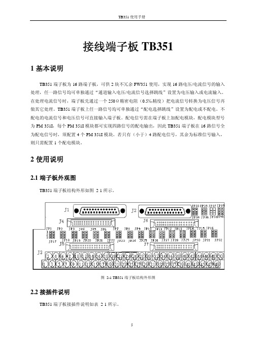
2使用说明2.1端子板外观图TB351端子板结构外形如图 2-1所示。
图 2-1 TB351端子板结构外形图2.2接插件说明TB351端子板接插件说明如表 2-1所示。
表 2-1 TB351端子板接插件说明标号说明J1 第一块卡数据连线插座J2 第二块卡数据连线插座J3 接线端子J4 第1、2、3、4路信号的配电小模块插槽J5 第5、6、7、8路信号的配电小模块插槽J6 第9、10、11、12路信号的配电小模块插槽J7 第13、14、15、16路信号的配电小模块插槽JP1~JP40 功能跳线2.3跳线说明TB351端子板跳线说明如表 2-2所示。
表 2-2 TB351端子板跳线说明标号说明使用JP1 第1路电压/电流信号输入选择跳线跳1-2:电流输入;跳2-3:电压输入JP2 第2路电压/电流信号输入选择跳线跳1-2:电流输入;跳2-3:电压输入JP3 第3路电压/电流信号输入选择跳线跳1-2:电流输入;跳2-3:电压输入JP4 第4路电压/电流信号输入选择跳线跳1-2:电流输入;跳2-3:电压输入JP5 第5路电压/电流信号输入选择跳线跳1-2:电流输入;跳2-3:电压输入JP6 第6路电压/电流信号输入选择跳线跳1-2:电流输入;跳2-3:电压输入JP7 第7路电压/电流信号输入选择跳线跳1-2:电流输入;跳2-3:电压输入JP8 第8路电压/电流信号输入选择跳线跳1-2:电流输入;跳2-3:电压输入JP9 第9路电压/电流信号输入选择跳线跳1-2:电流输入;跳2-3:电压输入JP10 第10路电压/电流信号输入选择跳线跳1-2:电流输入;跳2-3:电压输入JP11 第11路电压/电流信号输入选择跳线跳1-2:电流输入;跳2-3:电压输入JP12 第12路电压/电流信号输入选择跳线跳1-2:电流输入;跳2-3:电压输入JP13 第1路电压/电流信号输入选择跳线跳1-2:电流输入;跳2-3:电压输入JP14 第14路电压/电流信号输入选择跳线跳1-2:电流输入;跳2-3:电压输入JP15 第15路电压/电流信号输入选择跳线跳1-2:电流输入;跳2-3:电压输入JP16 第16路电压/电流信号输入选择跳线跳1-2:电流输入;跳2-3:电压输入JP17 第1路配电/不配电选择跳线跳1-2:配电;跳2-3:不配电JP18 第2路配电/不配电选择跳线跳1-2:配电;跳2-3:不配电JP19 第3路配电/不配电选择跳线跳1-2:配电;跳2-3:不配电JP20 第4路配电/不配电选择跳线跳1-2:配电;跳2-3:不配电JP21 第5路配电/不配电选择跳线跳1-2:配电;跳2-3:不配电JP22 第6路配电/不配电选择跳线跳1-2:配电;跳2-3:不配电JP23 第7路配电/不配电选择跳线跳1-2:配电;跳2-3:不配电JP24 第8路配电/不配电选择跳线跳1-2:配电;跳2-3:不配电JP25 第9路配电/不配电选择跳线跳1-2:配电;跳2-3:不配电JP26 第10路配电/不配电选择跳线跳1-2:配电;跳2-3:不配电JP27 第11路配电/不配电选择跳线跳1-2:配电;跳2-3:不配电JP28 第12路配电/不配电选择跳线跳1-2:配电;跳2-3:不配电JP29 第13路配电/不配电选择跳线跳1-2:配电;跳2-3:不配电JP30 第14路配电/不配电选择跳线跳1-2:配电;跳2-3:不配电JP31 第15路配电/不配电选择跳线跳1-2:配电;跳2-3:不配电JP32 第16路配电/不配电选择跳线跳1-2:配电;跳2-3:不配电JP33~JP38内/外配电方式选择跳线跳1-2:内配电;跳2-3:外配电JP39~JP40 配电输出时的24V/25.5V选择跳线跳1-2:配电输出24V;跳2-3:配电输出25.5Vz“内配电”指端子板无需外接24V电源,24V电源由卡件通过DB25线提供。
依米康空调控制器操作手册
控制屏是连接用户和机组的界面。K200 系列控制屏地独特设计,使屏的操作更为简单、方便。
4
3.2.1 控制屏 操作面板
状态指示灯
上图是前面板的 LED 指示灯,反应控制器的主要状态:电源开启、告警发生、机组 开关机状态。 Line (电源,黄色): 控制器上电。 Alarm (告警,红色): 机组告警(当告警出现时,蜂鸣器会被激活)。 On (运行,绿色): 机组经由按键或上级监控系统(取决于 EEPROM 的变量)的指令
:警惕标志。表明对该内容的操作要特别小心,否则会损坏空调机组或功能部
件。
1.款完全有可能引起以下的危险: -设备的重要功能失效 -对人造成电气或机械伤害 不遵守安全条款,则设备的保用无效,对设备损坏的申述也无效。
1.3 依米康空调主动的安全控制
空调机组的逻辑运行是由微处理器来控制的。微处理器也对机组各部位发生的任何故障和损坏进行有 效抑制和控制,这样控制了故障机器的进一步损坏和对人、环境引起危险。
设定湿度死区。当传感器 A14 测得的湿度处在死区时,驱动加湿器的 0~10V 输出为 0V,而除湿
亦不会被激活。
7
其中,用户参数以口令 22 访问;厂家参数、手动控制设置、复位默认参数设置都须以口令***
访问。此类参数的修改进入,须由我公司技术人员调整。
3.2.5 基本概念
主屏: 开机以后,控制屏所显示的内容,它包含了当前
控制器所采集的室内回风温度和回风湿度信息,还
当前温度: 23 ℃ 当前湿度: 50 %
键返回)
注意: 不能从访问一个级别的参数的状态直接转去访问另一个级别的参数,必须先 按 到根目录中,才能进入另一级别的参数。
参数修改:
PMC-851X综合保护测控装置用户说明书_V1.5_131014

美一IP网络对讲系统简易安装说明书概述
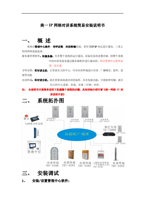
美一IP网络对讲系统简易安装说明书一、概述系统由管理中心软件、寻呼话筒、对讲终端组成,采用TCP/IP协议进行通讯,三者之间用网络连接起来。
服务器管理软件:即服务器,负责整个系统的运行通讯、设备信息的设置存储。
因整个系统中的对讲设备是通过服务器软件进行通讯的,所以管理中心软件必须一直开着寻呼话筒:即对讲主机,正常放在主控中心,可对对讲终端进行对讲、广播喊话、监听、监视等功能对讲终端:即对讲分机,放在需要求助或对讲的场所,具有免提功能;只要按呼叫键,就可向主控中心求助、咨询,实现(可视)对讲。
注:本说明书只是简单说明下组建整个系统的步骤,具体详细介绍可看《美一网络IP对讲说明手册》二、系统拓扑图三、安装调试1、安装/设置管理中心软件:(1)安装管理中心软件:将管理中心安装在目标电脑上,支持windowsServers2003、XP、Win7,Win8操作系统,安装过程中有提示安装.net2.0和Visual2005 C++ Redistributable Package2个插件,要全部安装。
如果忘记安装,安装包可以在程序的安装目录下的tools文件夹(软件名称DotNetFx和vcredist_x86)下找到。
(2)登入系统:默认用户名为admin,密码为123456,退出密码也是123456;(3)设置服务器IP地址:“系统”菜单,进入“系统设置”进行服务器IP设置,“服务器IP”输入框填入本机电脑的IP地址,“域”暂时没用到,默认就行。
电脑的IP地址要是固定的IP地址,不要动态获取。
设置完重启管理中心软件。
(4)增加设备:点击“列表”模式,上方工具栏会显示增加、删除按钮。
先选择左边树形菜单的“所有终端”分组,然后点击工具栏的“增加终端”按钮,进入窗口后,选择好要增加的类型,输入“终端ID”(ID号为8位数字,寻呼话筒以2开头,对讲终端以1开头),输入“终端名称”,点“确定”保存。
2、寻呼话筒连接(1)连接电源:12V的DC电源。
新科美国项35机分体直流变频空调控制器功能说明书(V01)
新科美国项35机分体挂壁式直流变频空调控制器控制说明书版本:V01编制:审核:批准:修改记录:版本号修改日期修改内容1、主题内容与适用范围1.1 本控制器功能说明书规定了直流变频空调电控制器的基本控制功能。
1.2 本控制器功能说明书适用于直流变频空调器。
2、引用标准和主要技术指标2.1除另行规定外,控制器应符合以下引用标准QB/T2263-1996《房间空气调节器电子控制器》GB/T14536.1-93《家用和类似用途电自动控制器通用部分》GB5956-91《房间空调器电器设备的安全要求》GB4343.2-1999《电磁兼容家用电器、电动工具和类似器具的要求第2部分抗扰度产品类标准》GB17625.1-1998《低压电气及电子设备发出的谐波电流限值(设备每相输入电流≤16A)》GB17625.2-1999《电磁相容限值对额定电流不大于16A的设备在低压供电系统中产生的电压波动和闪烁的限制》GB4706.1-1992《家用和类似用途电器的安全通用要求》2.2控制器应符合以下要求:2.2.1 控制器遥控接收距离≥8米,遥控接收锥度角≥60°。
2.2.2 温度控制误差≤±0.5℃,测量误差小于±0.5℃。
2.2.3 电流控制误差≤0.3A。
2.2.4 电压控制误差≤5V。
2.2.5 定时时间控制误差:≤2min/24h。
2.2.6 控制器额定电源: 220V 50/60Hz。
2.2.7 控制器电源使用范围:160~265V 50/60Hz2.2.8 室内电机转速控制误差±10转/分2.2.9 工作环境温度范围:室外控制器工作温度:-20℃~65℃,室内控制器工作温度:-20℃~65℃3、控制器输入、输出3.1控制器输入、输出信号:室内侧室外侧输入信号输出信号输入信号输出信号室内进风温度RT 室内风机信号室外进风温度压缩机控制信号室内盘管温度IPT 导风电机信号室外盘管温度外风机控制遥控信号显示压缩机排气温度四通阀控制信号按键信号(运转MODE设定键)室内通讯信号室内通讯信号室外通讯信号室外通讯信号变频模块保护信号电子膨胀阀控制信号机型选择信号3.2控制器对象3.2.1压缩机:1-1.5HP无刷直流电机,额定输入功率≤1500W3.2.2室外风机:单相异步电机AC220V 50Hz,额定输入功率≤120W;全直流机型使用直流无刷电机,输入功率≤60W3.2.3四通阀线圈:AC220V 50/60Hz,额定输入功率≤10W3.2.4室内风机:AC220V 50Hz(PG电机),额定输入功率≤50W ;全直流机型使用直流无刷电机,输入功率≤20W3.2.5导风电机:四相八拍步进电机3.2.6 健康组件:AC220V 50Hz,额定输入功率≤5W(预留)3.2.7 辅助电加热组件:AC220V 50Hz,额定输入功率≤1500W(预留)4、功能概述4.1 控制器基本运转模式控制器具有制冷、除湿、送风、制热以及自感等5种运行模式(详见第5节:控制器运行模式)4.2 控制器的设定温度控制器在送风模式下不存在设定温度,除湿、制冷、制热模式下的设定温度范围为16℃~30℃。
AT-MX351 SmartMixer 自动混音器安装和操作指南说明书

AT-MX351 SmartMixer Automatic MixerInstallation and Operation1. Power switch.2. Power “on” indicator.3. Input Gain controls. Adjust inputs for microphone sensitivities and/oroperating conditions.4. Selected Channel LED indicators. Indicate which channels are “on” or “active.”5. Aux In control. Adjusts input for source output level and/or operating conditions.6. Output Level LED meter. Indicates RMS output level of the mixer. “Zero” (0) level isfactory calibrated for an output of +4 dBm into 600 ohms (Master level control fullyclockwise). Can be set for peak output level indication via internal switch (see page 10).7. Priority Pre-select switches (1-4). A switch in the “up” position assigns the respectivechannel priority over the other channels. A priority channel can not be locked out byother channels. Any combination of priority/non-priority selections is allowed.8. Manual mode switch. Setting this switch in the “up” position bypasses all of theSmartMixer’s automatic functions, except limiting and NOMA if selected.9. Lockout LED indicator. Shows when lockout bus is active.10. Master level control. Adjusts mixer output level for operating conditions.11. Headphone output.1/” TRS jack.12. Monitor headphone level control.Figure 1. Front panel61. External Control connector. For TTL output, plus closure-control input for externalcontrol of each channel.2. Link In/Link Out. Provides for daisy-chaining of multiple mixers when more than fourmicrophones are used.3. Line/Mic balanced output. Level can be changed via internal switch (see page 10).XLRM-type connector.4. Unbalanced line-level (–10 dBV) output. RCA jack.5. Aux In. Unbalanced, line-level (–10 dBV), auxiliary input.6. Preamp Outputs. Independent, unbalanced (–10 dBV), switchable pre/post-controlleroutputs from mic channels.7. Inputs. Balanced microphone inputs for low-impedance dynamic or condenser mics.Can be changed to line-level inputs via internal switches (see page 10). XLRF-typeconnectors. Can supply 48V phantom power via internal switches.8. Power input. 120V/230V AC, 50/60 Hz. Select input voltage via switch on bottom panel.Figure 2. Rear panel78Mode 2…Priority Pre-select switches (1-4) DownIn this mode, only one mic at a time can be “on.” The lockout bus shuts down all other mics until the first speaker pauses. As soon as the controlling microphone goes silent, the lockout bus goes inactive and any other mic can come on. This switching takes place without anysyllable-grabbing delay, or pops or clicks. (This mode is known as “First-come-first-served”or “Filibuster.”)This mode is very useful when the gain setting of the overall sound system must be close to the threshold of feedback, and additional microphones coming on could throw the system into feedback. The SmartMixer will not allow multiple microphones to be on at the same time in this mode. The switching is so fast and silent that the meeting can still be completely interactive.Mode 3…One Priority Pre-select switch UpThe selected priority microphone can come on at any time and can mute any other mic that is on (popularly called “The Chairperson” mode).(Note that there may be special circumstances where two or three mics could be set to priority, so those speakers could talk whenever desired, but still mute one or two non-priority mics.)If multiple SmartMixers are used with AT8325/1.0 Link Cables, Priority Pre-select switches on all channels in use will have the control effects described above.The selected priority microphone(s) will mute only those non-priority microphones within the same unit.NOMAThe NOMA is factory set in the “off” position. To turn on the NOMA function, unplug the unit, remove the top cover and change the setting of the switch designated on the circuit board by “SW25” (Figs. 4 and 5, page 11).NOMA serves to maintain overall system gain by proportionately reducing amplifier gain as the number of open microphones increases. In a sound reinforcement system, this can tend to preserve the feedback margin and system stability. However, this action necessarily reduces the sound level of each individual person speaking, which may not be desired. In the end,use of NOMA often comes down to the preferences of the system’s designer and/or operator.Generally speaking, use of NOMA is not desirable in applications such as teleconferencing,recording or broadcasting.Auxiliary InputThe Aux input is an RCA jack accepting auxiliary-level (–10 dBV) input from sources such as tape decks and VCRs. There is no signal processing of the Aux input.Preamplifier GainThe SmartMixer has a substantial gain range, allowing it to accept a wide variety of micro-phones. However, if in some instances higher-output microphones are used for close talking, it may be necessary to reduce the preamplifier gain. This can be done by changing switchsettings inside the unit. With the unit unplugged from its AC source, remove the two screws on each side of the unit and carefully lift off the top cover. Locate the internal switchesdesignated on the circuit board by “SW2,” “SW8,” “SW14” and “SW20” (Figs. 4 and 5, page 11).A “control map” drawing will be found on the inside of the top cover. Changing the settingsof these internal switches will cause a gain reduction of 10 dB for channels 1, 2, 3 and 4respectively.9The preamplifier gain may be reduced further, allowing the SmartMixer to accept line-level sources. Changing the settings of the internal switches designated by “SW3,” “SW9,” “SW15”and “SW21” will cause an input reduction of 50 dB for channels 1, 2, 3 and 4 respectively.Note that the appropriate internal switches can be used in combination for a total sensitivity reduction of up to 60 dB for each channel.Output LevelThe SmartMixer’s output is factory set at line level. Should mic-level output be desired,simply unplug the unit, remove the top cover and locate the switch on the circuit boardmarked “SW26” (Figs. 4 and 5, page 11). Changing the setting of this switch will cause a50 dB reduction in output.Phantom PowerEach of the SmartMixer’s inputs supplies +48V DC phantom power. Should it be requiredto disable the phantom power, simply unplug the unit, remove the top cover and locate the switches designated on the circuit board by “SW1,” “SW7,” “SW13” and “SW19” (Figs. 4 and 5, page 11). Changing the settings of these switches will disable phantom power on channels 1, 2, 3 and 4, respectively. Note that, although they do not require phantom power for operation, most balanced-output dynamic microphones can be used without disabling the SmartMixer’s phantom power.Output Level LED MeterThe Output Level LED meter is factory set to indicate RMS output. Should peak outputindication be desired, simply unplug the unit, remove the top cover and change the setting of the switch designated on the circuit board by “SW27” (Figs. 4 and 5, page 11). “Zero” (0) level is factory-calibrated at +4 dBm into 600 ohms.10Summary of Internal ControlsFunction Ch 1 Ch 2 Ch 3 Ch 4 Output 48V Phantom Power SW1 SW7 SW13 SW1910 dB Input Atten. SW2 SW8 SW14 SW2050 dB Mic/Line Atten. SW3 SW9 SW15 SW21 SW26 Limiters (on/off) SW4 SW10 SW16 SW22“Off” Atten. Range SW5 SW11 SW17 SW23Preamp Output Gating SW6 SW12 SW18 SW24Limiter Thresholds VR2 VR5 VR8 VR11“Off” Atten. Adjustment VR3 VR6 VR9 VR12NOMA -- -- -- -- SW25 Meter RMS/Peak -- -- -- -- SW27Figure 3. Summary of internal controlsFigure 5. Detail of internal controls.Rear Panel11Mic SW3–40 dBSW5–20 dB–40 dBSW11–20 dB–40 dBSW17–20 dB–40 dBSW23–20 dBPhantom OffSW130 dB SW240 dBPhantom OffSW730 dB SW840 dBPhantom OffSW1330 dBSW1440 dBPhantom OffSW1930 dBSW2040 dBSW22OffOnSW4OffOnSW10OffOnSW16OffOnSW27Peak RMSMeter OffOnSW25NOMALineMicOutpu tSW26MicSW9MicLineSW15SW21SW6SW12SW18SW24GatingGatingGatingGatingOff OffOffOffAdjusting ”Off” AttenuationIn instances when the number of microphones in use is high, it may be necessary to increase the amount of “off” attenuation per microphone to keep the total ambient noise level low.There are “off” attenuation adjustments inside the unit. To adjust the “off” attenuation ofchannel 1, unplug the unit, remove the top cover and locate the trimpot designated on thecircuit board by “VR3” (Figs. 4 and 5, page 11). It is factory set at approximately 8 dB, theattenuation at the middle of the control’s rotation. When the control is turned fully counter-clockwise, “off” attenuation is approximately 20 dB. Conversely, when the adjustment isturned fully clockwise, “off” attenuation is approximately 6 dB. VR6, VR9 and VR12 control “off” attenuation for channels 2, 3 and 4 respectively.Changing the settings of the switches designated on the circuit board by “SW5,” “SW11,”“SW17” and SW23” will extend the range of “off” attenuation to –40 dB for channels 1, 2, 3 and 4 respectively.Preamp OutputsEach microphone channel has an independent unbalanced preamp output that is separatefrom the main mixer output. This is helpful when it is necessary to record the output of each channel, whether or not it is the active mixer output (as is required, for example, in somecourtroom proceedings). As set at the factory, no gating is applied to these outputs. To gate these outputs, unplug the unit, remove the top cover and locate the switches designated on the circuit board by “SW6,” “SW12,” “SW18” and SW24” (Figs. 4 and 5, page 11). Change the switch position(s) to “Gating” for channels 1, 2, 3 and/or 4 respectively, as desired.Input LimitersIndependent, adjustable limiters are available on all mic channels. To adjust the limiterthreshold of channel 1, unplug the unit, remove the top cover and locate the trimpot designated on the circuit board by “VR2” (Figs. 4 and 5, page 11). It is factory set at approximately 0 dB RMS. When the control is turned fully counter-clockwise, limiter threshold is approximately –10 dB RMS. Conversely, when the adjustment is turned fully clockwise, limiter threshold is approximately +10 dB RMS. VR5, VR8 and VR11 adjust limiter threshold for channels 2, 3 and 4 respectively.Changing the settings of the switches designated on the circuit board by “SW4,” “SW10,”“SW16” and SW22” will turn off the threshold-limiting function on channels 1, 2, 3 and 4respectively.Force-on/Force-offTo activate force-on/force-off, install a closure between the appropriate pin and GroundReference on the External Control connector on back of unit.12External Control Connector PinoutPin 1 Channel 1 force off Pin 8 Channel 4 force on Pin 2 Channel 2 force off Pin 9 Channel 1 TTL out Pin 3 Channel 3 force off Pin 10 Channel 2 TTL out Pin 4 Channel 4 force off Pin 13 Ground reference Pin 5 Channel 1 force on Pin 14 Channel 3 TTL out Pin 6 Channel 2 force on Pin 15 Channel 4 TTL out Pin 7 Channel 3 force onDriving LampsGCVDriving Logic GatesEquivalent Output Circuit for ControlVoltage Out Relay Driver Control Voltage OutWhen a microphone channel turns “on,” as indicated by a Selected Channel LED on the front panel, the channel’s associated Control Voltage Out goes “high” (+4 VDC). See chart on page 12 for pin connection. This signal can be used to light indicator lamps, switch speaker zones on and off, select video cameras, etc. The control voltage should not be connected directly to an inductive load such as a relay coil, as damage to the mixer may result. Several interface circuit possibilities are shown in Figure 6 below.Figure 6. Control interface examples.13Daisy-chaining MixersWhen more than four microphones are needed, it is possible to daisy-chain multipleSmartMixers together through the Link In/Out connectors on their back panels (Fig. 2).Connect Mixer #1 Link Out jack to Mixer #2 Link In jack, etc. Mixer #1 output contains onlyaudio from the first four microphones; Mixer #2 output then contains audio from all themicrophones plugged into Mixer #1 and the microphones plugged into Mixer #2. The lastmixer in the chain contains audio from all preceding mixers. The combined output is thentaken from the last mixer in the chain. Because lockout information is passed between mixersthrough Link In/Out, the last-microphone-on condition is not violated. Thus only onemicrophone per installation will stay on when no one is speaking.Note that one or more mixers can be switched to “Manual” mode without affecting theautomatic operation of any other mixers in the chain.NOMA information is passed between AT-MX351 mixers through Link In/Out. If AT-MX351mixers are linked with AT-MX341 and/or AT-MX341a mixers, the NOMA function will passthrough the AT-MX341(a) models but their mics will not be included in the NOMA calculation.Rack MountingProvided with each mixer are two rack ears and six self-tapping screws to attach the ears tothe unit, which allow the unit to be mounted in a 1U rack space.Security CapsFor permanent installations where microphone selections, positions and acoustic conditionsare constant, it may be advantageous to remove the front panel knobs and install securitycaps to prevent unauthorized adjustments. To install, simply press the caps into place,covering the desired control(s). The system should be tested carefully before installing thesecurity caps because they are intended to be “permanent” and are very difficult to remove.If removal of installed security caps becomes necessary, unplug the mixer, remove the twoscrews on each side of the unit and remove the top cover. Then remove the nine screws thatattach the front panel: six on top and three underneath. Remove the front panel. With thepanel removed, the two locking tabs on each security cap can be accessed. The cap can bereleased by carefully squeezing the two tabs together.1415One-Year Limited WarrantyAudio-Technica brand products purchased in the U.S.A. are warranted for one year from date of purchase by Audio-Technica U.S., Inc. (A.T.U.S.) to be free of defects in materials and workmanship. In event of such defect, product will be repaired promptly without charge or,at our option, replaced with a new product of equal or superior value if delivered to A.T.U.S. or an authorized service center prepaid, together with the sales slip or other proof of purchase date. Prior approval from A.T.U.S. is required for return.This warranty excludes defects due to normal wear, abuse, shipping damage, or failure to use product in accordance with instructions. This warranty is void in the event of unauthorized repair or modification.For return approval and shipping information, contact the Service Department, Audio-Technica U.S., Inc., 1221 Commerce Drive, Stow, Ohio 44224.Except to the extent precluded by applicable state law, A.T.U.S. will have no liability for any consequential, incidental, or special damages; any warranty of merchantability or fitness for particular purpose expires when this warranty expires.This warranty gives you specific legal rights, and you may have other rights which vary from state to state.Outside the U.S.A., please contact your local dealer for warranty details.Audio-Technica U.S., Inc., 1221 Commerce Drive, Stow, Ohio 44224 330/686-2600P52032-revA ©2007 Audio-Technica U.S., Inc. Printed In Japan。
PM-351I使用手册
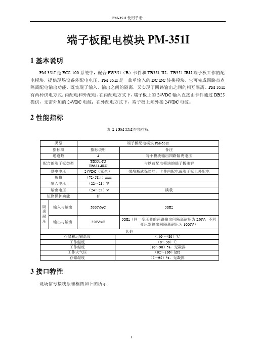
端子板配电模块PM-351I1 基本说明PM-351I 是ECS-100系统中,配合FW351(B )卡件和TB351-IU 、TB351-IRU 端子板工作的配电模块,提供现场设备外配电电压。
PM-351I 是一款单输入的DC-DC 转换模块,它可完成四路点点隔离配电输出功能,既实现了输入、输出之间的隔离,又实现了四路输出之间的相互隔离。
PM-351I 有两种供电方式:内配电和外配电。
在内配电方式下,端子板上的24VDC 输入直接由卡件通过DB25提供,无需外加的24VDC 电源;在外配电方式下,端子板上须外接24VDC 电源。
2 性能指标表 2-1 PM-351I 性能指标3 接口特性现场信号接线原理框图如下图所示:类型 端子板配电模块PM-351I指标项 指标说明备注通道数4每个模块输出四路隔离电压 配合的端子板类型TB351-IUTB351-IRU与以前配电模块的端子板兼容供电电压 24VDC (冗余)带熔断式保险丝,卡件内配电或端子板上外配电规格 (72×58.4)mm 输入电压 (22~28)V 输出电压 (24~27)V满载 短路保护功能 有输入与输出3000V AC 50Hz隔离耐压输出与输出 250V AC50Hz (同一变压器的两路输出间隔离耐压为250V ,不同变压器输出间隔离耐压为1000V ) 其他存储和运输温度 (-40~+80)℃ 工作温度 (0~50)℃工作湿度 (10~90)%,无凝露 工作大气压 (62~106)kPa 存储湿度(5~95)%,无凝露图 3-1配电模块接口特性图(以TB351-IRU为例)如上图所示,配电模块PM-351I和端子板上的接插件连接,通过端子板上的端子给外接变送器提供电压。
现场的电流信号通过采样电阻转换为电压信号后,通过DB25返送到卡件。
TB351-IU、TB351-IRU和现场信号的连接请分别参见《TB351-IU接线端子板使用手册》和《TB351-IRU接线端子板使用手册》。
Pelco PP350, PP351, PP450, PP451 光电监控系统手册说明书

® Pelco, the Pelco logo, Spectra, Esprit, Genex, Legacy, and Camclosure are registered trademarks of Pelco.™ Endura and ExSite are trademarks of Pelco.© Copyright 2004, Pelco. All rights reserved.REVISION HISTORYManual #Date CommentsC212M-A 5/99Rev. A. Combined model PP350, PP351, PP450, and PP451 into one manual. Updated product description, installation instructions, and specifications. Added certifications.C212M-B 5/01Revised Figure 2 with new dimensions.C212M-B8/04Removed agency logo on cover; updated Warranty and Return information.WARRANTYPelco will repair or replace, without charge, any merchandise proved defective in material or workmanship for a period of one year after the date of shipment.Exceptions to this warranty are as noted below:• Five years on FT/FR8000 Series fiber optic products.• Three years on Genex Series products (multiplexers, server, and keyboard).• Three years on Camclosure and fixed camera models, except the CC3701H-2,CC3701H-2X, CC3751H-2, CC3651H-2X, MC3651H-2, and MC3651H-2X camera models, which have a five-year warranty.• Two years on standard motorized or fixed focal length lenses.• Two years on Legacy , CM6700/CM6800/CM9700 Series matrix, and DF5/DF8 Series fixed dome products.• Two years on Spectra , Esprit , ExSite , and PS20 scanners, including when used in continuous motion applications.• Two years on Esprit and WW5700 Series window wiper (excluding wiper blades).• Eighteen months on DX Series digital video recorders, NVR300 Series network video recorders, and Endura™ Series distributed network-based video products.months on DX Series digital video recorders, NVR300 Series network video recorders, Endura Series distributed network-based video products, and TW3000 Series twisted pair transmission products.• One year (except video heads) on video cassette recorders (VCRs). Video heads will be covered for a period of six months.• Six months on all pan and tilts, scanners or preset lenses used in continuous motion applications (that is, preset scan, tour and auto scan modes).Pelco will warrant all replacement parts and repairs for 90 days from the date of Pelcoshipment. All goods requiring warranty repair shall be sent freight prepaid to Pelco, Clovis,California. Repairs made necessary by reason of misuse, alteration, normal wear, or accident are not covered under this warranty.Pelco assumes no risk and shall be subject to no liability for damages or loss resulting from the specific use or application made of the Products. Pelco’s liability for any claim,whether based on breach of contract, negligence, infringement of any rights of any party or product liability, relating to the Products shall not exceed the price paid by the Dealer to Pelco for such Products. In no event will Pelco be liable for any special, incidental or consequential damages (including loss of use, loss of profit and claims of third parties)however caused, whether by the negligence of Pelco or otherwise.The above warranty provides the Dealer with specific legal rights. The Dealer may also have additional rights, which are subject to variation from state to state.If a warranty repair is required, the Dealer must contact Pelco at (800)289-9100 or(559) 292-1981 to obtain a Repair Authorization number (RA), and provide the following information:1. Model and serial number2. Date of shipment, P .O. number, Sales Order number, or Pelco invoice number3. Details of the defect or problemIf there is a dispute regarding the warranty of a product which does not fall under the warranty conditions stated above, please include a written explanation with the product when returned.Method of return shipment shall be the same or equal to the method by which the item was received by Pelco.RETURNSIn order to expedite parts returned to the factory for repair or credit, please call the factory at (800) 289-9100 or (559) 292-1981 to obtain an authorization number (CA number if returned for credit, and RA number if returned for repair).All merchandise returned for credit may be subject to a 20% restocking and refurbishing charge.Goods returned for repair or credit should be clearly identified with the assigned CA or RA number and freight should be prepaid. Ship to the appropriate address below.If you are located within the continental U.S., Alaska, Hawaii or Puerto Rico, send goods to:Service Department Pelco625 W. AlluvialFresno, CA 93711If you are located outside the continental U.S., Alaska, Hawaii or Puerto Rico and are instructed to return goods to the USA, you may do one of the following:If the goods are to be sent by a COURIER SERVICE, send the goods to:Pelco625 W. AlluvialFreno , CA 93711 USA If the goods are to be sent by a FREIGHT FORWARDER, send the goods to:Pelco c/o Expeditors 473 Eccles AvenueSouth San Francisco, CA 94080 USA Phone: 650-737-1700Fax: 650-737-0933WARRANTY AND RETURN INFORMATIONIMPORTANT SAFEGUARDS AND WARNINGSPrior to installation and use of this product, the following WARNINGS should be observed.1.Installation and servicing should only be done by qualified service personnel and conform to all local codes.2.Installation shall be done in accordance with all local and national electrical and mechani-cal codes utilizing only approved materials.3.Use only installation methods and materials capable of supporting four times the maxi-mum specified load.e stainless steel hardware to fasten the mount to outdoor surfaces.5.To prevent damage from water leakage when installing a mount outdoors on a roof or wall, apply sealant around the bolt holes between the mount and mounting surface.Please thoroughly familiarize yourself with the information in this manual prior to installation and operation.C212M-B (8/04)PP350/PP450 Parapet Mount PP351/PP451 Rooftop Mount625 W. Alluvial Fresno , CA 93711 USAIn North America & Canada: Tel (800) 289-9100FAX (800) 289-9150International Customers: Tel (1-559) 292-1981FAX (1-559) DESCRIPTIONThe PP350 and PP351 mounts were designed for outdoor use with small-size pendant domes,and the PP450 and PP451 are for outdoor use with medium-size pendant domes. The PP350and PP450 models mount to parapets, while the PP351 and PP451 models mount to rooftops or other smooth horizontal surfaces. All models accommodate domes that use 1.5-inch NPT pipe.The PP450 and PP451 can be used in applications where mounting and height clearances of models PP350 and PP351 are inadequate. Models PP450 and PP451 are higher by 9.72inches (24.69 cm) and the overhang is increased by 14.77 inches (37.52 cm).The mounts are designed to swivel within available clearance limits, which adds to the flexibility,easy maintenance, and usability of the configuration.Manufactured from aluminum, the mounts include indexing bolts to secure the arm in position.ModelsPP350Parapet mount for small-size pendant domes; mounts to inside or outside of parapet.PP351Rooftop or smooth horizontal surface mount for small-size pendant domes.PP450Same as PP350 except overhang clearance and height accommodate medium-size pendant domes.PP451Same as PP351 except overhang clearance and height accommodate medium-size pendant domes.INSTALLATION Before BeginningThe hardware to install the mount depends on your installation requirements. The mount has pre-drilled holes for use with 3/8-16 type hardware. (This hardware is not included with themount.) Use as many of the mounting holes as possible. Pelco recommends 3/8-16 type fasten-ing hardware. Multiple fastening positions facilitate mounting flexibility. For models PP350 and PP450, mount using a minimum of three fasteners on each side of the mounting plate. For models PP351 and PP451, mount using a minimum of two fasteners on each side of themounting base. If necessary to prevent damage from water leakage, you should also have seal-ant (not supplied) to apply around the bolt holes between the mount and mounting surface.Installing the Mount1.Loosen the nuts holding the brake mounting plate. Loosen the nuts only enough to pullthe arm out of the guide hoops (see Figure 1).2.Remove the arm.3.Install the mount.PP350/PP450Install the mounting plate to the inside or the outside of the parapet. Use a minimum of three fasteners on each side of the mounting plate. Depending on the type of parapetconstruction, install the mounting plate as close to the top of the parapet as possible. If the mounting plate is installed two to five inches from the top of the parapet, you canswing the dome back for maintenance as necessary (the dome will clear the top of the parapet). If necessary to prevent water damage, apply sealant around the bolt holes be-tween the mount and mounting surface.PP351/PP451Install the mounting base to the rooftop or other smooth horizontal surface. Use a mini-mum of two fasteners on each of the four sides of the mounting base (a minimum total of eight fasteners). If necessary to prevent water damage, apply sealant around the boltholes between the mount and mounting surface.4.Reinstall the arm; lower the arm through the guide hoops until it stops at the bottom ofthe mounting plate.5.Pull the wires through the arm starting from the bottom of the mounting plate; pull thewires out through the threaded opening at the top of the arm.6.Pull the wires through the dome, and attach the dome to the end of the arm.7.Make all electrical connections.8.Move the arm and dome into the desired position.9.Secure the brake mounting plate against the arm; tighten the nuts on the studs that holdthe brake mounting plate in place.10.To hold the arm in position, tighten the indexing bolts near the center of the brake mount-ing plate. If desired, drill into the arm through the holes in the brake mounting plate, install the indexing bolts, and tighten. Important . . . Do not drill into existing wiring that may be pulled through the arm.BRAKEPLATEBOLTSFigure 1. Mounting Diagram SPECIFICATIONSMaterial:AluminumMounting Method:3/8-16 fasteners; minimum of 6 for PP350/PP450; minimum of 8 for PP351/PP451Maximum Load:45 lb (20.41 kg)Dimensions:See Figure 2Finish:Gray polyester powder coatWeightPP350:9.30 lb (4.22 kg)PP351:20.19 lb (9.16 kg)PP450:10.38 lb (4.71 kg)PP451:22.53 lb (10.22 kg)(Design and product specifications subject to change without notice.)Figure 2. PP350, PP351, PP450, PP451 Dimension Drawing。
PME快速入门手册

PME现场调试操作手册一、综述兴化城南污水厂,采用了GE RX3i系列PLC,经查询资料,该系列PLC应该属于GE换代产品,从外观到性能都很像老款的GE90-30系列PLC,属于中档产品,可以用于实时性不是很高但是需要长期连续运行的工程现场。
RX3i系列PLC采用的编辑软件为GE Proficy Machine Edition(简称PME),需要8.0及以上编程软件。
二、常用菜单打开PME程序会显示下面的几个菜单,主要用到的都在这里,比如左侧的XHCN,项目根目录,PLC1~PLC5和SLC1~SLC6是我定义的11个PLC的工程名,下面的Message是主要的反馈信息,这些信息在调试的时候非常重要、一定要仔细阅读,会有利于系统调试。
最右边是梯形图常用命令。
三、基本操作1、打开工程第一次打开PME或者点File—Open,均会出现下列界面自上而下分部是创建一个空工程、创建一个ME模板工程和打开已存在最近打开过的工程。
这里的XHCN是我自己创建的工程。
点OK打开项目2、工程首页3、创建工程节点在XHCN上点击右键,会出现Add Target菜单,选择到PAC RX3i系统系统会自动在最下面生成一个PAC项目,并自动创建相关硬件配置、程序模块等基本模块4、配置硬件在导航页,点击Hardware Configuration,可以对硬件参数进行配置,这里如果有的CPU含网口,则必须在配置完CPU后填写IP地址信息,否则将会硬件报错。
四、系统调试1、调试参数配置在工程节点上点右键,选择最下面的Porperties弹出一个小对话框这里有选定工程的相关参数,拉动滑块到最下面,有一个Physical Port选项,这个选项是编程软件与PLC的通信端口,默认是COM1,需要调整到ETHERNET,并填入PLC的IP地址2、设置活动工程在进行PLC调试时,每次只能对一个PLC进行调试,所以,需要在调试时设置活动工程,在需要设置为活动工程的工程上点右键,选择Set as Active Target,选择后,对应的工程会变成加宽的黑色字体。
SEL351使用手册简化版
目录一.继电器介绍、定货选型和安装 (3)1.介绍 (3)2. 定货选型 (4)3.继电器安装 (7)二.继电器元件与功能 (8)三.面板按钮操作 (8)1.概述 (8)2.通过前面板修改显示定值 (9)3.通过前面板观察继电器内部字位 (10)4.通过前面板在液晶中显示表计数据 (10)5.通过前面板在液晶中显示事故报告摘要 (11)6.初始状态下的液晶显示 (11)7.改变当前运行定值组 (11)8.前面板上其它功能键 (11)四.串口通信和命令 (11)1.串口通信 (11)2.串口命令 (12)3.SEL-351继电器串口命令摘要 (14)BRE命令(断路器监视数据) (14)COMM命令(通讯数据) (14)DAT命令(查看/改变日期) (16)EVE命令(事件) (16)GRO命令(显示运行整定值组号) (16)HIS命令(事件摘要/历史) (16)IRI命令(与IRIG-B时间码同步) (17)LDP命令(负荷存档报告) (18)MET命令(表计数据) (18)MET k-瞬时量表计 (18)MET D-需求量表计 (19)MET E-能量表计 (19)MET E-能量表计 (20)QUI命令(退出命令处理层) (20)SER命令(顺序事件记录器报告) (20)SHO命令(显示/查看整定值) (21)STA命令(继电器自检状态) (24)STA命令行和列定义 (24)TAR命令(显示继电器元件状态) (25)继电器字位(用于SELogic控制方程) (25)TIM命令(查看/改变时间) (28)TRI命令(触发事件报告) (28)命令处理层B命令 (28)BRE n命令(预载/复归断路器损耗) (28)CLO命令(闭合断路器) (29)GRO n命令(改变运行整定值组) (29)OPE命令(打开断路器) (30)PUL命令(脉冲输出接点) (30)命令处理层2命令 (30)CON命令(控制远方位) (30)COP m n命令(拷贝整定值组) (31)LOO命令(闭环检测) (31)PAS命令(查看/改变口令) (32)SET命令(改变整定值) (32)五.跳闸和信号逻辑 (32)附录A. 整定单附录B. 继电器保护逻辑一.继电器介绍、定货选型和安装1.介绍主要特性和优点SEL-351继电器是一种集保护、监视、控制和故障定位于一体的保护装置。
TB351-IU使用手册
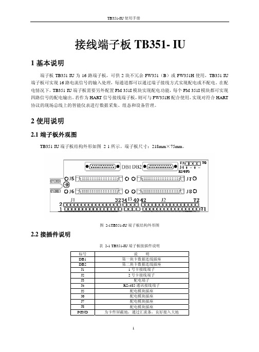
接线端子板TB351- IU1基本说明端子板TB351-IU为16路端子板,可供2块不冗余FW351(B)或FW351H使用,TB351-IU 端子板可实现16路电流信号的输入处理,每通道都可以通过端子接线方式实现配电或不配电。
在配电情况下,TB351-IU端子板需要另外配置PM-351I模块实现配电功能,每个PM-351I模块都可实现四路信号的配电输出。
若作为HART信号接线端子板,则可与FW351H配合使用,实现对符合HART 协议的现场总线上的智能仪表进行数据采集、组态和设备管理。
2使用说明2.1端子板外观图TB351-IU端子板结构外形如图 2-1所示。
端子板尺寸:218mm×75mm。
图 2-1TB351-IU端子板结构外形图2.2接插件说明表 2-1 TB351-IU端子板接插件说明标号说明DB1 第一块卡数据连线插座DB2 第二块卡数据连线插座J1 1号卡接线端子J2 2号卡接线端子J3 配电端子J4 RS-485通讯接线端子J5 配电模块插座J6 配电模块插座J7 配电模块插座J8 配电模块插座PGND 为卡件屏蔽地,通过汇流条,良好接入大地2.3接口特性图 2-2接口特性1(以第一通道为例,配电)图 2-3接口特性2 (以第一通道为例,不配电)2.4端子定义及接线当信号源为有源变送器时,J3接线端子需要将33与34、35与36、37与38、39与40用导线连起来;当信号源为无源变送器时,端子板可采用内配电和外配电两种配电方式。
当采用内配电(通过卡件供电)时,J3接线端子与信号源为有源变送器时的接线保持一致;当采用外配电(外部电源供电)时,需要将33与34、35与36、37与38、39与40之间的导线断开,然后在34、36之间接一路电源A,38、40之间接另一路电源B ;RS485+表示HART设备管理网络的RS-485通讯正端,RS485-表示RS-485通讯负端。
2.4.1 内配电信号端子接线表 2-2 内配电信号端子接线卡号接线图(内配电)信号端子接线 通道1(CH1)1 2 3 4 - + 不接线 不接线通道2(CH2)5 6 7 8 - + 不接线 不接线通道3(CH3)9 10 11 12 - + 不接线 不接线通道4(CH4)13 14 15 16 - + 不接线 不接线通道5(CH5)17 18 19 20 - + 不接线 不接线通道6(CH6)21 22 23 24 - + 不接线 不接线通道7(CH7)25 26 27 28 - + 不接线 不接线通道8(CH8)29 30 31 32 - + 不接线 不接线配电端子33 34 35 36 一 号 卡(33、34)短接,(35、36)短接配电端子37 38 39 40 (37、38)短接,(39、40)短接通道9(CH9)41 42 43 44 - + 不接线 不接线通道10(CH10)45 46 47 48 - + 不接线 不接线通道11(CH11)49 50 51 52 - + 不接线 不接线通道12(CH12)53 54 55 56 - + 不接线 不接线通道13(CH13)57 58 59 60 - + 不接线 不接线通道14(CH14)61 62 63 64 - + 不接线 不接线通道15(CH15)二 号 卡65 66 67 68- + 不接线 不接线通道16(CH16)69 70 71 72 - + 不接线 不接线2.4.2 外配电信号端子接线表 2-3 外配电信号接线端子卡号接线图(外配电)信号端子接线 通道1(CH1)1 2 3 4 - + 不接线 不接线通道2(CH2)5 6 7 8 - + 不接线 不接线通道3(CH3)9 10 11 12 - + 不接线 不接线通道4(CH4)13 14 15 16 - + 不接线 不接线通道5(CH5)17 18 19 20 - + 不接线 不接线通道6(CH6)21 22 23 24 - + 不接线 不接线通道7(CH7)25 26 27 28 - + 不接线 不接线通道8(CH8)29 30 31 32 - + 不接线 不接线配电端子33 34 35 36一号 卡不接线24V A+不接线 24V A-配电端子37 38 39 40不接线24VB+不接线 24VB- 通道9(CH9)41 42 43 44 - + 不接线 不接线通道10(CH10)45 46 47 48 - + 不接线 不接线通道11(CH11)49 50 51 52 - + 不接线 不接线通道12(CH12)53 54 55 56 - + 不接线 不接线通道13(CH13)57 58 59 60 - + 不接线 不接线通道14(CH14)61 62 63 64 - + 不接线 不接线通道15(CH15)65 66 67 68 - + 不接线 不接线通道16(CH16)69 70 71 72 二 号 卡- + 不接线 不接线2.4.3 不配电信号端子接线表 2-4 不配电信号端子接线卡号 接线图(不配电)信号端子接线 通道1(CH1)1 2 3 4不接线不接线- + 通道2(CH2)5 6 7 8不接线不接线- + 通道3(CH3)9 10 11 12不接线不接线- + 通道4(CH4)13 14 15 16不接线不接线- + 通道5(CH5)17 18 19 20不接线不接线- + 通道6(CH6)21 22 23 24不接线不接线- + 通道7(CH7)25 26 27 28不接线不接线- + 通道8(CH8)29 30 31 32不接线不接线- + 配电端子33 34 35 36 一 号 卡不接线不接线不接线 不接线配电端子37 38 39 40 不接线不接线不接线 不接线通道9(CH9)41 42 43 44不接线不接线- + 通道10(CH10)45 46 47 48不接线不接线- + 通道11(CH11)49 50 51 52不接线不接线- + 通道12(CH12)53 54 55 56不接线不接线- + 通道13(CH13)57 58 59 60不接线不接线- + 通道14(CH14)61 62 63 64不接线不接线- + 通道15(CH15)65 66 67 68二 号 卡不接线不接线- +通道16(CH16)69 70 71 72不接线不接线- +2.4.4HART通信端子接线图 2-4 HART通信端子接线示意图有关HART通信端子接线的说明请参见《FW351H使用手册》。
3551说明书

HIOKI使用手册HIOKI E.E公司3551型电池寿命测试仪内 容介绍 (1)验收 (1)安全 (1)预防措施 (2)手册的组织结构 (4)第1章 概要 (5)1.1 产品概要 (5)1.2 产品特征 (5)第2章 测试仪及功能介绍 (6)第3章 规格说明 (9)3.1 基本参数 (9)3.2 测试范围 (11)3.2.1 最大工作额定电压 (12)3.2.2 绝缘强度 (13)第4章 标准测量 (14)4.1 准备测量 (14)4.1.1 更换电池 (14)4.1.2 连接9418-10交流适配器 (15)4.1.3 测试线和外控开关的连接 (15)4.2 测量电池 (15)4.2.1 测量注意事项 (15)4.2.2 测量 (16)第5章 高级测量功能 (18)5.1 比较器功能 (18)5.1.1 比较器功能的介绍 (18)5.1.2 设置比较器 (18)5.1.3 比较器结果裁决表 (19)5.1.4 启动或关闭比较器 (20)5.1.5 改变比较器的编号 (20)5.2 存储测量值 (20)5.2.1 存储 (21)5.2.2 覆写 (21)5.2.3 清除 (21)5.2.4 读数 (22)5.2.5 打印 (22)5.3 关闭或启动蜂鸣器功能 (23)5.4 锁屏功能 (24)5.5 移动平均数功能 (24)5.6 零调节功能 (24)5.6.1 9465测试线的零调节 (24)5.6.2 9460测试线的零调节 (25)5.7 电池低电压警告 (25)5.8 自动关机模式 (26)5.9 “EXT. HOLD”端和“EXT. MEMO”端的电路图 (27)5.10复位 (27)5.11交流四终端法 (28)5.12铅蓄电池的内阻 (28)第6章 维护 (29)6.1 故障及解决 (29)6.2 参考信息 (30)6.3 清洁 (30)----------------------------------------介绍感谢你购买HIOKI 电池测试仪。
美意三位一体机组通用说明书
(一)机组特点 (3)(二)机组数据 (5)(三)机组安装 (6)(四)保养和维护 (9)(五)电气 (10)(六)开机运行 (11)一.机组特点(随机附件)压 力 表温 度 计下的性能参考。
一致,恕不另行通知。
1、本产品在制冷工况下,当源水侧进水温度小于20℃时,可增加流量旁通阀,可减小水流量,保证机组出水温度在25℃以上。
建议制冷工况负载侧不要长期在过高的出水温度下使用,其结果可能导致压缩机润滑油的碳化,影响压缩机的正常使用。
2、当本产品机组源水侧出水温度低于2℃,请在水系统中加入防冻液,以防机组系统冻坏。
3、在用生活热水要求出水55℃时,为保证机组的可靠运行,要求源水侧在额定水流下进水温度不低于7℃。
4、以上进出水温限定范围均在额定水流量下。
5、由于该机组采用高效板式换热器,应在冬季环境温度过低机组停用时,将水系统内水排除干净,以避免板换水路系统结冰;若机组长期不用,则必须将水系统内水排除干净,开启水泵,从排水法兰处放水或拆开后面板,从水泵放水阀放水,以免冻裂板换及水系统管路。
6、机组长期运行中的蒸发压力与冷凝压力须在下列运行极限范围内(蓝色线框内):在设置及移装空调器时,制冷循环系统内除了规定的制冷剂(R22)以外不要让空气等混入。
如有空气等混入则制冷循环6 水管连接示意图有机磷 mg/l机组内部如此线在出厂前均已完成并做好了绝缘防开机前准备 ¾ 机组安装、调试、运行、维修之前,请仔细阅读随机的安装使用说明书!首次调试必须在本公司调试工程师的指导下进行。
¾ 检查电气接线是否松动,如有松动应立即拧紧。
¾ 检查系统压力是否正常,是否有泄漏的可能。
¾ 确保相序正确,电压符合机组电源要求。
¾ 温度传感器位置合理,接触可靠。
¾ 点动源水泵确保旋向正确。
¾ 水流量符合铭牌参数¾ 机组运行前应确保所有部件无损伤,电源电压及频率、水系统正常! ¾ 电源要求按照以下要求执行:1) 允许电压范围:360~415V(GB12325规定为额定电压±7%以内) 2) 允许频率范围:±2%以内(GB/T15945规定为±0.2Hz 以内)3)允许三相电压不平衡量:±2%以内(GB12326规定为2.5%以内; GB/T15543规定为2%以内)4) 允许三相电流不平衡量:±5%以内上述准备工作均已完成任务,并确保无误,可以按下开机按钮,进入正常开机操作,此时,应密切注意机组运行态,运行指标应符合上述各条要求。
MCO351调试
8、电机\编码器减速比:参数19-14和19-15。例如如果电机转 5转编码器转2转,则19-14设为5,19-15设为2。 9、点动设置:参数19-16(点动速度)、参数19-17(点动斜 坡时间,单位毫秒)。 10、位置环PID参数自动计算:参数19-19,设为2即可自动计 算出位置环参数。该参数为理论计算值,如果需要达到最优, 还需手动调整。 11、定位点设置:参数19-23(定位点索引)、参数19-24(定 位点移动的位置)、参数19-25(定位运行加速时间,毫 秒)、19-26(定位运行减速时间,毫秒)、参数19-27(定 位运行速度,RPM)。参数19-28(定位方式:0-绝对定位、 1-相对定位、2\3探针定位) 。针对每一个位置的定位动作 都可以独立设置定位方式、速度、加速、减速。 12、参数保存:参数19-29,设为1,参数保存,保存完成后自 动回零。
MCO351定位控制器
一、端子定义:
二、硬件结构:
三、定位卡相关参数设置
1、确认编码器轴所对应的最高转速(RPM),设置在参数3280中。缺省速度和缺省加速度都设置为50(%值,参数32-84 和32-85)。 2、模式选择:参数19-01,0:定位控制、1:变频器控制。 3、控制来源选择:参数19-04,0:端子控制、1:总线控制。 4、故障行为:参数19-06,0:电磁制动、1:机械制动。 5、自动制动控制:参数19-09,0:禁止、1:激活,当电动机 处于停止状态,经过参数19-12设定的延时时间,自动激活制 动。 6、根据制动的机械特性设置制动抱闸延时和制动释放延时(参 数19-10和19-11) 7、制动磨损限制:参数19-13,如果设置不为零,自动激活制 动磨损报警有效。如果在制定过程中编码器移动的脉冲数大 于设置的值,变频器报制动磨损报警。
- 1、下载文档前请自行甄别文档内容的完整性,平台不提供额外的编辑、内容补充、找答案等附加服务。
- 2、"仅部分预览"的文档,不可在线预览部分如存在完整性等问题,可反馈申请退款(可完整预览的文档不适用该条件!)。
- 3、如文档侵犯您的权益,请联系客服反馈,我们会尽快为您处理(人工客服工作时间:9:00-18:30)。
端子板配电模块
PM-351I
1 基本说明
PM-351I 是ECS-100系统中,配合FW351(B )卡件和TB351-IU 、TB351-IRU 端子板工作的配电模块,提供现场设备外配电电压。
PM-351I 是一款单输入的DC-DC 转换模块,它可完成四路点点隔离配电输出功能,既实现了输入、输出之间的隔离,又实现了四路输出之间的相互隔离。
PM-351I 有两种供电方式:内配电和外配电。
在内配电方式下,端子板上的24VDC 输入直接由卡件通过DB25提供,无需外加的24VDC 电源;在外配电方式下,端子板上须外接24VDC 电源。
2 性能指标
表 2-1 PM-351I 性能指标
3 接口特性
现场信号接线原理框图如下图所示:
类型 端子板配电模块PM-351I
指标项 指标说明
备注
通道数
4
每个模块输出四路隔离电压 配合的端子板类型
TB351-IU
TB351-IRU
与以前配电模块的端子板兼容
供电电压 24VDC (冗余)
带熔断式保险丝,卡件内配电或端子板上外配电
规格 (72×58.4)mm 输入电压 (22~28)V 输出电压 (24~27)V
满载 短路保护功能 有
输入与输出
3000V AC 50Hz
隔离耐压
输出与输出 250V AC
50Hz (同一变压器的两路输出间隔离耐压为250V ,不同
变压器输出间隔离耐压为1000V ) 其他
存储和运输温度 (-40~+80)℃ 工作温度 (0~50)℃
工作湿度 (10~90)%,无凝露 工作大气压 (62~106)kPa 存储湿度
(5~95)%,无凝露
图 3-1配电模块接口特性图(以TB351-IRU为例)
如上图所示,配电模块PM-351I和端子板上的接插件连接,通过端子板上的端子给外接变送器提供电压。
现场的电流信号通过采样电阻转换为电压信号后,通过DB25返送到卡件。
TB351-IU、TB351-IRU和现场信号的连接请分别参见《TB351-IU接线端子板使用手册》
和《TB351-IRU接线端子板使用手册》。
4使用说明
4.1配电模块外观结构图
PM-351I配电模块外观结构图如图 4-1所示。
图 4-1 PM-351I配电模块外观结构图
4.2接插件说明
PM-351I端子板接插件说明如表 4-1所示:
表 4-1 PM-351I端子板接插件说明
标号说明
J1 配电模块和端子板连接器
5应用注意事项
配电模块插入端子板之后,外壳两端的螺丝需拧紧。
6资料版本说明
表 6-1版本升级更改一览表
资料版本号更改说明
PM-351I使用手册(V1.0)适用硬件版本:PM-351I-V40.00.00。
