ILC-0603中文资料
国巨压敏电阻产品0402-0603两型号

VR
0402 / 0603
5.5 V to 38 V
CONSTRUCTION Lead Free terminations, NiSn terminations Surface mount multilayer surge suppressor Very short response time (<1.0 nsec) Bidirectional clamping Low capacitance for high frequency applications Very low leakage current
VARISTOR/ MAX. WORKING CLAMPING PEAK LEAKAGE CURRENT BREAKDOWN VOL. VOL.@1A CURRENT R.T. (15~35 °C) VOL. DC @1mA D.C (max.) 8/20 µS (max.) 8/20 µS (max.) Voltage Current
ORDERING INFORMATION - GLOBAL PART NUMBER, PHYCOMP CTC & 12NC All part numbers are identified by the series, size, tolerance, TC material, packing style, voltage, process code, termination and capacitance value. YAGEO BRAND ordering code GLOBAL PART NUMBER (PREFERRED )
10 V ~ 14 V 10 V ~ 14 V 10 V ~ 14 V 10 V ~ 14 V 7.2 V ~ 10.8 V 7.2 V ~ 10.8 V 7.2 V ~ 10.8 V 7.2 V ~ 10.8 V 7.2 V ~ 10.8 V 7.2 V ~ 10.8 V 10.8 V ~ 13.2 V 10.2 V ~ 13.8 V 10.2 V ~ 13.8 V 18 V ~ 24 V 18 V ~ 24 V 18 V ~ 24 V 14.4 V ~ 21.6 V 16.2 V ~ 19.8 V 90 V ~ 135 V 50 V ~ 80 V 50 V ~ 80 V 24 V ~ 34 V 24 V ~ 34 V 24 V ~ 34 V 24 V ~ 34 V 24 V ~ 34 V 24 V ~ 34 V 21.6 V ~ 26.4 V 24 V ~ 34 V 27 V ~ 38 V 50 V ~ 80 V 5.5 V 5.5 V 5.5 V 5.5 V 5.5 V 5.5 V 5.5 V 5.5 V 5.5 V 5.5 V 9V 9V 9V 14 V 14 V 14 V 14 V 14 V 18 V 18 V 18 V 18 V 18 V 18 V 18 V 18 V 18 V 18 V 18 V 19 V 30 V 22 V 22 V 22 V 22 V 18 V 18 V 18 V 18 V 18 V 18 V 22 V 22 V 22 V 38 V 38 V 38 V 35 V 33 V 250 V 130 V 130 V 66 V 66 V 66 V 66 V 66 V 66 V 56 V 66 V 60 V 130 V 2A 4A 6A 10 A 10 A 15 A 15 A 20 A 20 A 30 A 6A 6A 15 A 7A 15 A 15 A 20 A 20 A 1A 1A 2A 3A 3A 3A 4A 4A 4A 10 A 15 A 15 A 1A 5.5 V 5.5 V 5.5 V 5.5 V 5.5 V 5.5 V 5.5 V 5.5 V 5.5 V 5.5 V 9V 9V 9V 14 V 14 V 14 V 14 V 14 V 18 V 18 V 18 V 18 V 18 V 18 V 18 V 18 V 18 V 18 V 18 V 19 V 18 V 10 µA 10 µA 10 µA 10 µA 10 µA 10 µA 10 µA 10 µA 10 µA 10 µA 20 µA 20 µA 20 µA 20 µA 20 µA 20 µA 20 µA 20 µA 10 µA 10 µA 10 µA 10 µA 10 µA 10 µA 10 µA 10 µA 10 µA 35 µA 10 µA 4 µA 10 µA
耐冲击电阻 0603

耐冲击电阻 0603电子产品现在已经成为人们生活中不可或缺的一部分,而耐冲击电阻0603作为其中的重要组件之一,起着至关重要的作用。
它能够保护电路免受外界冲击和干扰,确保电子设备的正常运行。
本文将对耐冲击电阻0603的特点和应用进行详细阐述。
一、耐冲击电阻0603的特点耐冲击电阻0603采用了先进的制造技术和材料,具有以下几个主要特点:1. 小巧精致:耐冲击电阻0603的尺寸仅为0.06英寸×0.03英寸(即1.6毫米×0.8毫米),体积非常小巧。
这使得它能够在电路板上占用更少的空间,为其他元件留出更多的空间,有利于电路的设计和布局。
2. 高耐冲击能力:耐冲击电阻0603采用了耐压材料制作而成,能够承受较大的冲击和振动,不易受到外界环境的干扰。
这使得电子设备能够在恶劣的环境中长时间运行,保证产品的可靠性和稳定性。
3. 低电阻值:耐冲击电阻0603具有较低的电阻值,能够提供稳定的电流传输和热量分散。
这对于电路的正常运行至关重要,能够有效地减少电流紊乱和电器设备发热的问题。
4. 宽温度范围:耐冲击电阻0603能够在较宽的温度范围内工作,通常从-55℃到+155℃。
这使得它非常适用于各种环境温度变化较大的场合,例如汽车电子、航空航天等领域。
二、耐冲击电阻0603的应用领域耐冲击电阻0603由于其优异的特点,在各个领域都有广泛的应用。
以下是它的几个主要应用领域:1. 通信设备:耐冲击电阻0603在手机、平板电脑、路由器等通信设备中扮演重要的角色。
它可以确保信号的传输稳定,提高通信质量,减少干扰和噪音,保证通信设备顺利运行。
2. 汽车电子:耐冲击电阻0603广泛应用于汽车电子系统中,如发动机控制单元(ECU)、制动系统、导航系统等。
它能够保护电子设备不受汽车震动和冲击的影响,提高整个汽车电子系统的可靠性和稳定性。
3. 工业控制:耐冲击电阻0603在工业控制设备中起着重要作用,用于保护设备免受电磁干扰和电压冲击的影响。
r0603手册

r0603手册
摘要:
1.引言
2.r0603 手册的概述
3.r0603 手册的主要内容
4.r0603 手册的实际应用
5.总结
正文:
r0603 手册是一本关于机器人技术和人工智能的综合性指南,为读者提供了机器人技术领域的基础知识和实践方法。
在概述部分,r0603 手册介绍了机器人技术的基本概念和发展历程,阐述了人工智能在机器人技术中的重要作用。
同时,手册还详细介绍了r0603 机器人的硬件结构和功能特点,为读者提供了对机器人基本构成的全面认识。
r0603 手册的主要内容包括机器人的运动控制、传感器数据处理、通信与网络技术以及人工智能算法等方面的知识。
手册从基础原理出发,结合实际应用案例,为读者提供了丰富的实践方法和技巧。
此外,手册还涵盖了机器人在不同领域的应用,如工业生产、医疗保健、家庭服务等,为读者展示了机器人技术的广泛应用前景。
在实际应用部分,r0603 手册以r0603 机器人为例,详细介绍了如何进行机器人的编程和调试。
此外,手册还提供了丰富的案例分析和实践教程,帮助读者更好地理解和掌握机器人技术的实际应用。
总之,r0603 手册是一本全面、实用的机器人技术和人工智能指南。
无论是初学者还是有经验的工程师,都可以从这本手册中获得有价值的知识和实践方法。
tcc0603x7r104k101ct 的规格书
tcc0603x7r104k101ct 的规格书一、产品概述tcc0603x7r104k101ct 是一款高性能的无线通信芯片,适用于各种无线通信应用场景。
该芯片采用先进的无线通信技术,具有高速数据传输、低功耗、低成本等优点,是未来无线通信领域的发展趋势。
二、技术规格1. 频率范围:XX-XXGHz2. 调制方式:XX、XX等3. 数据传输速率:XXMbps4. 蓝牙版本:5.X5. 发射功率:XXmW(典型值)6. 接收灵敏度:XXdBm(典型值)7. 功耗:XXmW(待机状态)8. 芯片尺寸:XXmm x XXmm9. 工作电压:XXV-XXV10. 工作温度:-XX℃至+XX℃三、芯片特点1. 高性能:支持高速数据传输,适用于各种高速无线通信应用场景。
2. 集成度高:集成了蓝牙、Wi-Fi等多种无线通信模块,降低了系统成本和复杂性。
3. 功耗低:待机状态功耗低,适合长时间使用。
4. 兼容性强:支持多种蓝牙版本,可满足不同用户需求。
5. 易于集成:封装尺寸小,便于在现有电路板上集成。
6. 可靠性高:经过严格的质量控制和测试流程,确保产品性能稳定可靠。
四、应用领域tcc0603x7r104k101ct 适用于各种需要无线通信功能的设备,如蓝牙耳机、智能家居、物联网设备、智能穿戴设备等。
五、接口说明1. TX/RX 数据接口:用于数据的发送和接收,支持高速数据传输。
2. VCC、GND:芯片供电接口,提供稳定的电压和接地信号。
3. RF_EN:射频工作使能端,用于控制芯片的射频工作状态。
4. S_CLK:串行数据串口时钟信号,用于控制数据的传输速度和传输模式。
5. MCU_TXD:微控制器数据发送端,可将微控制器的数据发送给芯片进行调制。
6. MCU_RXD:微控制器数据接收端,可从芯片接收已调制的无线信号数据。
六、软件配置为充分发挥 tcc0603x7r104k101ct 的性能,需要相应的软件支持。
PRC0603中文资料

0.014% 0.005% 0.014% 0.007% 0.000% 0.002% 0.194% 0.158% 0.250% 0.003% 0.002% 0.003% 0.005% 0.003% 0.007% 0.013% -0.024% -0.033%
100% MEET SPECIFICATION 0.012% 0.000% 0.012% 0.083% 0.005% 0.018% 0.052% 0.017% 0.018% -0.009% -0.018% -0.008% 0.002% 0.001% 0.008% -0.057% -0.009% -0.001% -0.001% -0.001% 0.000% 0.027% 0.003% 0.012% 0.009% 0.007% 0.007%
Result
Value Max. Min. Avg.
Specification ∆R within ±0.5% ∆R within ±0.25% ∆R within ±0.5% ∆R within ±0.25% without mechanical damage. ∆R within ±0.25% without mechanical damage. ∆R within ±0.1% Minimum 95% of the electrode surface covered. ∆R within ±0.25% ∆R within ±0.25% ∆R within ±0.5%
(0.60±0.25)
P W
L
Operating Temperature Range is -55°C to +125°C * -20°C to +85°C
H
Temperature Coefficients
RC0603中文资料

Thick Film Chip Resistor – General PurposeFeatures• Small and light weight• Excellent heat resistance and moisture resistance• Suitable size and packaging for surface mount assembly • RoHS CompliantApplications• For general purpose applications• For laptop and notebook computer, memory module, digital camera and telecommunication equipmentAbsolute Maximum Ratings & CharacteristicsProductNumbermm TolerancePower Rating @70˚CMAX Working Voltage MAXOverload VoltageTCR ppm/℃Resistance RangeRated WorkingTemperature±200 1Ω ~ 9.76Ω±100 10Ω ~ 1M ΩRC0603 1608J: ±5%F: ±1%1/10W 50V 100V ±2001.02M Ω ~ 10M Ω-55℃~+155℃*JumperProduct NumberJumper Rated CurrentResistanceRated Working Temperature RC0603 1A 50m Ω (max.)-55℃~+155℃RC0603 Power Derating CurveFor resistors operate in the ambient temperature over 70˚C, loading power ratio will de-rate in accordance with following curve.Soldering ConditionIR Reflow soldering Wave soldering (flow soldering)RC0603Dimensions(in mm)Product Number mm L W H AB Average Weight RC060316081.60 ± 0.100.80± 0.100.45 ± 0.100.30 ± 0.200.30 ± 0.202.02 mgMarking(1) ±5% Tolerance (J): 3 digits, the first two digits are significant figures; the third digit is numberof zeros to follow. Letter “R” is as decimal point; Letter “0” for jumper.(2) ±1% Tolerance (F): E–96 marking series as in the end. (E-96 series marking code Table)Examples:3 digits marking (±5%) E-96 marking (±1%)683 = 68x103 Ω Jumper 49X = 316x10-1Ω = 68000 Ω = 68K Ω = 31.6 Ω 7R 5 = 7.5 ΩRC0603 Test and RequirementsRequirement Test Item Test Method Test Condition±1% ±5% JumperTemperature Coefficient of Resistance(T.C.R.) JIS C 5201 4.8IEC 60115-1 4.8-55°C~+155,20°C isthe referencetemperatureWithin the specificationShort Time Overload JIS C 5201 4.13IEC 60115-1 4.132.5 times RCWV or max.overload voltage for 5seconds±(1.0%+0.05Ω) ±(2.0%+0.05Ω) <50mΩInsulation Resistance JIS C 5201 4.6IEC 60115-1 4.6Max. overload voltagefor 1 minute≥10GVoltage Proof JIS C 5201 4.7IEC 60115-1 4.71.42 times RCWV(RMS) for 1 minuteno breakdown or flashoverSubstrate Bending Test JIS C 5201 4.33IEC 60115-1 4.33Bending once with 5seconds for 3 mm±(1.0%+0.05Ω) ±(1.0%+0.05Ω) <50mΩResistance to soldering heat JIS C 5201 4.18IEC 60115 4.18260±5°C for 10 seconds±(0.5%+0.05Ω) ±(1.0%+0.05Ω) <50mΩLeaching JIS C 5201 4.18IEC 60115 4.18260±5°C for 60 seconds no leachingSolderability JIS C 5201 4.17IEC 60115-1 4.17245±5°C for 3 seconds. >95% coverageEndurance at upper category temperature JIS C 5201 4.23IEC 60115-1 2.23.2at +155°C for 1000 hrs ±(1.0%+0.05Ω) ±(1.5%+0.10Ω) <50mΩRapid change of temperature JIS C 5201 4.19IEC 60115-1 4.19-55°C to +155°C, 5cycles±(0.5%+0.05Ω) ±(1.0%+0.05Ω) <50mΩDamp heat with load JIS 5201 4.2440±2°C, 90~95% R.H.or max. working voltagefor 1000 hrswith 1.5hrs “ON” and 0.5hrs “OFF”±(2.0%+0.10Ω) ±(3.0%+0.10Ω) <100mΩEndurance JIS C 5201 4.25IEC 60115-1 4.25.170±2°C, RCWV or Max.working voltage for 1000hrs with 1.5 hrs“ON” and 0.5 hrs “OFF”±(2.0%+0.10Ω) ±(3.0%+0.10Ω) <100mΩNote: RCWV:Rated Continuous Working Voltage.RCWV= √Rated power (W) × Resistance value (R)RC0603Packing Information:Carrier Tape Dimensions (in mm)TypeABWEF P0 P1 P2ψD0T RC0603 1.10±0.1 1.90±0.1 8.0±0.2 1.75±0.13.5±0.054.0±0.14.0±0.052.0±0.05 1.5+0.1/-00.70±0.1Reel Dimensions (in mm)Reel DiameterPCS per ReelABCWT7’’ 5,000 180+0/-360+1/-0 13.0±0.29.0±0.5 11.4±1 13’’ 20,000 330±1 100±1 13.0±0.29.5±0.5 13.5±1Carton InformationPCS per CartonCarton Size300,000 400X400X200 ( in mm)RC0603 Table - E-96 series marking code (±1% Tolerance)Code R value Code R value Code R value Code R value Code R value Code R value Code R value Code R value01 100 13 133 25 178 37 237 49 316 61 422 73 562 85 75002 102 14 137 26 182 38 243 50 324 62 432 74 576 86 76803 105 15 140 27 187 39 249 51 332 63 442 75 590 87 78704 107 16 143 28 191 40 255 52 340 64 453 76 604 88 80605 110 17 147 29 196 41 261 53 348 65 464 77 619 89 82506 113 18 150 30 200 42 267 54 357 66 475 78 634 90 84507 115 19 154 31 205 43 274 55 365 67 487 79 649 91 86608 118 20 158 32 210 44 280 56 374 68 499 80 665 92 88709 121 21 162 33 215 45 287 57 383 69 511 81 681 93 90910 124 22 165 34 221 46 294 58 392 70 523 82 698 94 93111 127 23 169 35 226 47 301 59 402 71 536 83 715 95 95312 130 24 174 36 232 48 309 60 412 72 549 84 732 96 976 This table shows the first two digits for the three-digit EIA-96 part marking scheme.The third character is the letter of multiplier: Y=10-2 X=10-1 A=100 B=101 C=102 D=103 E=104 F=105RC0603 How to OrderRC0603 How to contact us:。
ILC-0402中文资料
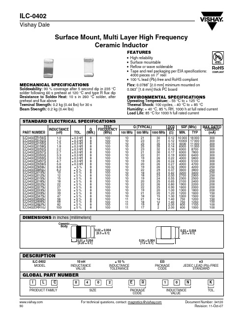
Surface Mount, Multi Layer High FrequencyCeramic Inductor For technical questions, contact: magnetics@Document Number: 3412090Revision: 11-Oct-07ILC-0402Vishay DaleFEATURES•High reliability•Surface mountable•Reflow or wave solderable•4000 pieces on 7" reel•100 % lead (Pb)-free and RoHS compliantMECHANICAL SPECIFICATIONSSolderability: 90 % coverage after 5 second dip in 235 °C solder following 60 s preheat at 120 °C and type R flux dip Resistance to Solder Heat: 10 s in 260 °C solder, after preheat and flux aboveTerminal Strength: 0.2 kg (0.44 lbs) for 30 s Beam Strength: 0.2 kg (0.44 lbs)Flex: 0.0788" [2.0 mm] minimum mounted on 0.063" [1.6 mm] thick PC boardENVIRONMENTAL SPECIFICATIONSOperating Temperature: - 55 °C to + 125 °C Thermal Shock: 100 cycles, - 40 °C to + 85 °CHumidity: + 40 °C, 85 % RH, 1000 h at full rated current Load Life: 85 °C for 1000 h full rated currentSTANDARD ELECTRICAL SPECIFICATIONSPART NUMBER INDUCTANCE(nH)TOL.Q (MIN.) TEST FREQUENCY (MHz) Q (TYPICAL) DCRMAX.(Ω)SRF (MHz) MAX. RATED CURRENT (mA)100 MHz 500 MHz 1000 MHz MIN.TYPILC0402ER1N0S ILC0402ER1N2S ILC0402ER1N5S ILC0402ER1N8S ILC0402ER2N2S ILC0402ER2N7S ILC0402ER3N3S ILC0402ER3N9S ILC0402ER4N7S ILC0402ER5N6S ILC0402ER6N8J ILC0402ER8N2J ILC0402ER10NJ ILC0402ER12NJ ILC0402ER15NJ ILC0402ER18NJ ILC0402ER22NJ ILC0402ER27NJ ILC0402ER33NJ ILC0402ER39NJ ILC0402ER47NJ ILC0402ER56NJ ILC0402ER68NJ ILC0402ER82NJ ILC0402ERR10J1.0 1.2 1.5 1.82.2 2.73.3 3.94.75.66.8 8.2 10 12 15 18 22 27 33 39 47 56 68 82 100± 0.3 nH ± 0.3 nH ± 0.3 nH ± 0.3 nH ± 0.3 nH ± 0.3 nH ± 0.3 nH ± 0.3 nH ± 0.3 nH ± 0.3 nH ± 5 % ± 5 % ± 5 % ± 5 % ± 5 % ± 5 % ± 5 % ± 5 % ± 5 % ± 5 % ± 5 % ± 5 % ± 5 % ± 5 % ± 5 %8 8 8 8 8 8 8 8 8 8 8 8 8 8 8 8 8 888 8 8 8 88100 100 100 100 100 100 100 100 100 100 100 100 100 100 100 100 100 100 100 100 100 100 100 100 10010 10 10 10 10 10 10 10 10 10 10 10 10 10 10 10 10 10 10 10 10 11 11 11 1121 23 25 25 23 21 22 19 19 20 19 22 18 18 19 20 22 22 19 21 18 21 18 19 1730 31 35 35 32 30 31 26 26 26 2629 23 23 24 25 26 25 20 20 15 14 12820.120.120.130.140.160.170.190.220.240.270.320.370.420.500.550.650.800.901.001.201.301.401.402.002.00 10 000 10000 6000 6000 6000 6000 6000 4000 4000 4000 3900 3600 3200 2700 2300 2100 1900 1600 1300 1200 1000 750 750 600 600 18 000 17 000 11 000 11 000 8700 7800 6400 5800 5100 4700 4200 3800 3400 2900 2500 2400 2200 2000 1800 1600 1500 1200 1250 1100 1000300300300300300300300300300300250250250250250200200200200150150150150100100元器件交易网Document Number: 91000Revision: 18-Jul-081DisclaimerLegal Disclaimer NoticeVishayAll product specifications and data are subject to change without notice.Vishay Intertechnology, Inc., its affiliates, agents, and employees, and all persons acting on its or their behalf (collectively, “Vishay”), disclaim any and all liability for any errors, inaccuracies or incompleteness contained herein or in any other disclosure relating to any product.Vishay disclaims any and all liability arising out of the use or application of any product described herein or of any information provided herein to the maximum extent permitted by law. The product specifications do not expand or otherwise modify Vishay’s terms and conditions of purchase, including but not limited to the warranty expressed therein, which apply to these products.No license, express or implied, by estoppel or otherwise, to any intellectual property rights is granted by this document or by any conduct of Vishay.The products shown herein are not designed for use in medical, life-saving, or life-sustaining applications unless otherwise expressly indicated. Customers using or selling Vishay products not expressly indicated for use in such applications do so entirely at their own risk and agree to fully indemnify Vishay for any damages arising or resulting from such use or sale. Please contact authorized Vishay personnel to obtain written terms and conditions regarding products designed for such applications.Product names and markings noted herein may be trademarks of their respective owners.元器件交易网。
常用电子制作IC型号、功能介绍全集

74HC573D 存储集成电路
IX0388CE 中频放大集成电路
SAA5290ZP 微处理集成电路
74HCT157 多路转换双输入集成电路 IX0411CEN1 微处理集成电路
SAA5297 微处理集成电路
74HCT4046A 压控振荡集成电路
IX0412CE 字符发生集成电路
微处理集成电路
74HC245 总线收发集成电路
理集成电路
SAA5261 电视信号处理集成电路
74HC32 或门四 2 输入集成电路
IX0365CE 伴音功率放大集成电路
SAA5281ZP 电视信号处理集成电路
74HC374 八 D 触发集成电路
IX0371GE 磁头控制集成电路
SAA5284 电视信号处理集成电路
87CK38N-3584 微处理集成电路
理集成电路
SAA9050 色度解码集成电路
87CK38N-3627 微处理集成电路
IX0603CE 视频、色度信号处理集成电路 SAA9051 色度解码集成电路
89C52 系统控制处理集成电路
IX0605CE 微处理集成电路
SAA9055 色度解码集成电路
89C55 系统控制处理集成电路
20810-F6096 存储集成电路
集成电路
路
2252B 微处理集成电路
IX0062CE 图像中频放大、视频放大集成电 S1D2503X01 视频信号处理 200MHz 集成
24C01ACEA 存储集成电路
路
电路
24C026 存储集成电路
IX0064CE 图像中频放大、检波、视频放大 S1D2512X01 偏转信号处理集成电路
74HC04 逻辑与非门集成电路
- 1、下载文档前请自行甄别文档内容的完整性,平台不提供额外的编辑、内容补充、找答案等附加服务。
- 2、"仅部分预览"的文档,不可在线预览部分如存在完整性等问题,可反馈申请退款(可完整预览的文档不适用该条件!)。
- 3、如文档侵犯您的权益,请联系客服反馈,我们会尽快为您处理(人工客服工作时间:9:00-18:30)。
Document Number: 34145For technical questions, contact: magnetics@Revision: 11-Oct-0791ILC-0603Vishay DaleSurface Mount, Multi Layer High FrequencyCeramic InductorFEATURES•High reliability•Surface mountable•Reflow or wave solderable•Tape and reel packaging per EIA specifications:4000 pieces on 7" reel•100 % lead (Pb)-free and RoHS compliantMECHANICAL SPECIFICATIONSSolderability: 90 % coverage after 5 s dip in 235 °C solder following 60 s preheat at 120 °C and type R flux dipResistance to S older Heat: 10 s in 260 °C solder, after preheat and flux aboveTerminal Strength: 0.3 kg (0.66 lbs) for 30 s Beam Strength: 0.3 kg (0.66 lbs)Flex: 0.0788" [2.0 mm] minimum mounted on 0.063"[1.6 mm] thick PC boardENVIRONMENTAL SPECIFICATIONSOperating Temperature: - 55 °C to + 125 °C Thermal Shock: 100 cycles, - 40 °C to + 85 °CHumidity: + 40 °C, 85 % RH, 1000 hat full rated current Load Life: 85 °C for 1000 h full rated currentSTANDARD ELECTRICAL SPECIFICATIONSPART NUMBER INDUCTANCE(nH)TOL.Q (MIN.) TEST FREQUENCY (MHz) Q (TYPICAL) DCRMAX. (Ω)SRF (MHz) MAX. RATED CURRENT (mA)100 MHz 500 MHz 1000 MHzMIN.TYPILC0603ER1N0S ILC0603ER1N2S ILC0603ER1N5S ILC0603ER1N8S ILC0603ER2N2S ILC0603ER2N7S ILC0603ER3N3S ILC0603ER3N9S ILC0603ER4N7S ILC0603ER5N6S ILC0603ER6N8J ILC0603ER8N2J IL C0603ER10NJ IL C0603ER12NJ ILC0603ER15NJ IL C0603ER18NJ IL C0603ER22NJ ILC0603ER27NJ ILC0603ER33NJ IL C0603ER39NJ ILC0603ER47NJ ILC0603ER56NJ IL C0603ER68NJ IL C0603ER82NJ IL C0603ERR10J IL C0603ERR12J IL C0603ERR15J IL C0603ERR18J ILC0603ERR22J ILC0603ERR27J1.0 1.2 1.5 1.82.2 2.73.3 3.94.75.66.8 8.2 10 12 15 18 22 27 33 39 47 56 68 82 100 120 150 180 220 270± 0.3 nH ± 0.3 nH ± 0.3 nH ± 0.3 nH ± 0.3 nH ± 0.3 nH ± 0.3 nH ± 0.3 nH ± 0.3 nH ± 0.3 nH ± 5 % ± 5 % ± 5 % ± 5 % ± 5 % ± 5 % ± 5 % ± 5 % ± 5 % ± 5 % ± 5 % ± 5 % ± 5 % ± 5 % ± 5 % ± 5 % ± 5 % ± 5 % ± 5 % ± 5 %8 8 8 8 8 10 10 10 10 10 10 10 12 12 12 12 12 12 12 12 12 12 12 12 12 8 8 8 8 8100 100 100 100 100 100 100 100 100 100 100 100 100 100 100 100 100 100 100 100 100 100 100 100 100 50 50 50 505015 14 11 10 14 12 16 11 11 15 15 13 15 12 15 15 17 15 15 14 17 19 17 16 16 17 19 18 18 194338 28 24 35 29 40 25 26 36 38 31 34 27 30 28 34 31 28 31 31 34 30 29 24 21 20 13 - -63 55 40 35 40 45 47 35 35 46 47 41 47 49 36 31 36 30 24 28 28 26 20 183 - - - - -0.05 0.05 0.10 0.10 0.10 0.10 0.12 0.14 0.16 0.18 0.22 0.24 0.26 0.28 0.32 0.35 0.40 0.45 0.55 0.60 0.70 0.75 0.85 0.95 1.00 1.20 1.20 1.30 1.50 1.6010 000 10 000 6000 6000 6000 6000 4000 3500 3500 3500 3000 3000 2800 2000 2000 1800 1800 1500 1200 1100 900 900 700 600 600 500 500 400 400350 15 000 14 000 13 000 11 000 10 000 7000 5900 4500 4500 40003600 3500 3000 2500 2200 2000 1900 1700 1500 1300 1300 1200 1000 1000 800 800 700 600 500 490300 300 300 300 300 300 300 300 300 300 300 300 300 300 300 300 300 300 300 300 300 300 300 300 300 300 300 300 300 300元器件交易网Document Number: 91000Revision: 18-Jul-081DisclaimerLegal Disclaimer NoticeVishayAll product specifications and data are subject to change without notice.Vishay Intertechnology, Inc., its affiliates, agents, and employees, and all persons acting on its or their behalf (collectively, “Vishay”), disclaim any and all liability for any errors, inaccuracies or incompleteness contained herein or in any other disclosure relating to any product.Vishay disclaims any and all liability arising out of the use or application of any product described herein or of any information provided herein to the maximum extent permitted by law. The product specifications do not expand or otherwise modify Vishay’s terms and conditions of purchase, including but not limited to the warranty expressed therein, which apply to these products.No license, express or implied, by estoppel or otherwise, to any intellectual property rights is granted by this document or by any conduct of Vishay.The products shown herein are not designed for use in medical, life-saving, or life-sustaining applications unless otherwise expressly indicated. Customers using or selling Vishay products not expressly indicated for use in such applications do so entirely at their own risk and agree to fully indemnify Vishay for any damages arising or resulting from such use or sale. Please contact authorized Vishay personnel to obtain written terms and conditions regarding products designed for such applications.Product names and markings noted herein may be trademarks of their respective owners.元器件交易网。