LT-4006S中文资料
L60S40资料

L25S 1 L25S 2 L25S 3 L25S 4 L25S 5 L25S 6 L25S 8 L25S 10 L25S 12 L25S 15 L25S 20 L25S 25 L25S 30 L25S 35 L25S 40 L25S 45 L25S 50 L25S 60 L25S 70 L25S 80 L25S 90 L25S 100 L25S 125 L25S 150 L25S 175 L25S 200 L25S 225 L25S 250 L25S 275 L25S 300 L25S 350 L25S 400 L25S 450 L25S 500 L25S 600 L25S 700 L25S 800 L50S 10 L50S 12 L50S 15 L50S 20 L50S 25 L50S 30 L50S 35 L50S 40 L50S 50 L50S 60 L50S 70 L50S 80 L50S 90 L50S 100 L50S 125 L50S 150 L50S 175 L50S 200 L50S 225 L50S 250 L50S 275 L50S 300 L50S 350 L50S 400 L50S 450 L50S 500 L50S 550 L50S 600 L50S 700 L50S 800
L15S 1 L15S 2 L15S 3 L15S 4 L15S 5 L15S 6 L15S 7 L15S 8 L15S 9 L15S 10 L15S 12 L15S 15 L15S 20 L15S 25 L15S 30 L15S 35 L15S 40 L15S 45 L15S 50 L15S 60 L15S 70 L15S 80 L15S 90 L15S 100 L15S 125 L15S 150 L15S 200 L15S 250 L15S 300 L15S 350 L15S 400 L15S 450 L15S 500 L15S 600 L15S 800 L15S 1000
1N4006RL中文资料

1N4001, 1N4002, 1N4003,1N4004, 1N4005, 1N4006,1N40071N4004 and 1N4007 are Preferred DevicesAxial Lead Standard Recovery RectifiersThis data sheet provides information on subminiature size, axial lead mounted rectifiers for general−purpose low−power applications. Features•Shipped in plastic bags, 1000 per bag•Available Tape and Reeled, 5000 per reel, by adding a “RL” suffix to the part number•Available in Fan−Fold Packaging, 3000 per box, by adding a “FF”suffix to the part number•These devices are manufactured with a Pb−Free external leadfinish only*Mechanical Characteristics•Case: Epoxy, Molded•Weight: 0.4 gram (approximately)•Finish: All External Surfaces Corrosion Resistant and Terminal Leads are Readily Solderable•Lead and Mounting Surface Temperature for Soldering Purposes: 220°C Max. for 10 Seconds, 1/16 in. from case•Polarity: Cathode Indicated by Polarity Band*For additional information on our Pb−Free strategy and soldering details, please download the ON Semiconductor Soldering and Mounting Techniques Reference Manual, SOLDERRM/D.CASE 59−10AXIAL LEADPLASTICLEAD MOUNTED RECTIFIERS50−1000 VOLTSDIFFUSED JUNCTIONPreferred devices are recommended choices for future use and best overall value.MARKING DIAGRAMSee detailed ordering and shipping information on page 3 of this data sheet.ORDERING INFORMATIONAL= Assembly Location1N400x= Device Numberx= 1, 2, 3, 4, 5, 6 or 7YY= YearWW= Work WeekAL1N400xYYWWMAXIMUM RATINGSvalues (not normal operating conditions) and are not valid simultaneously. If these limits are exceeded, device functional operation is not implied, damage may occur and reliability may be affected.ELECTRICAL CHARACTERISTICS*ORDERING INFORMATION†For information on tape and reel specifications, including part orientation and tape sizes, please refer to our Tape and Reel Packaging Specifications Brochure, BRD8011/D.PACKAGE DIMENSIONSAXIAL LEAD CASE 59−10ISSUE SDIM MIN MAX MIN MAX MILLIMETERSINCHES A 4.10 5.200.1610.205B 2.00 2.700.0790.106D 0.710.860.0280.034F −−− 1.27−−−0.050K25.40−−−1.000−−−NOTES:1.DIMENSIONING AND TOLERANCING PER ANSI Y14.5M, 1982.2.CONTROLLING DIMENSION: INCH.3.59−04 OBSOLETE, NEW STANDARD 59−09.4.59−03 OBSOLETE, NEW STANDARD 59−10.5.ALL RULES AND NOTES ASSOCIATED WITH JEDEC DO−41 OUTLINE SHALL APPLY6.POLARITY DENOTED BY CATHODE BAND.7.LEAD DIAMETER NOT CONTROLLED WITHIN F DIMENSION.ON Semiconductor and are registered trademarks of Semiconductor Components Industries, LLC (SCILLC). SCILLC reserves the right to make changes without further noticeto any products herein. SCILLC makes no warranty, representation or guarantee regarding the suitability of its products for any particular purpose, nor does SCILLC assume any liability arising out of the application or use of any product or circuit, and specifically disclaims any and all liability, including without limitation special, consequential or incidental damages.“Typical” parameters which may be provided in SCILLC data sheets and/or specifications can and do vary in different applications and actual performance may vary over time. All operating parameters, including “Typicals” must be validated for each customer application by customer’s technical experts. SCILLC does not convey any license under its patent rights nor the rights of others. SCILLC products are not designed, intended, or authorized for use as components in systems intended for surgical implant into the body, or other applications intended to support or sustain life, or for any other application in which the failure of the SCILLC product could create a situation where personal injury or death may occur. Should Buyer purchase or use SCILLC products for any such unintended or unauthorized application, Buyer shall indemnify and hold SCILLC and its officers, employees, subsidiaries, affiliates,and distributors harmless against all claims, costs, damages, and expenses, and reasonable attorney fees arising out of, directly or indirectly, any claim of personal injury or death associated with such unintended or unauthorized use, even if such claim alleges that SCILLC was negligent regarding the design or manufacture of the part. SCILLC is an Equal Opportunity/Affirmative Action Employer. This literature is subject to all applicable copyright laws and is not for resale in any manner.PUBLICATION ORDERING INFORMATION。
APU4006中文资料

APLUS APU4006FEATURES·Very low current dissipation.·Wide operating voltage range.·Supports both Ag and Li batteries.·Powerful instruction set.·4-level subroutine nesting (including interrupt).· 4 event driven interrupts, 2 external and 2 internal.·ROM size: 1024 x 15 bits.·RAM size: 48 x 4 bits.·Input ports: 1 port/ 4 pins (M-PORT).·Control output: ALARM.·LCD driver outputs (can drive up to 60 LCD segments).·Mask option to select 3 LCD drive modes: static, duplex 1/2 duty 1/2 bias, 1/3 duty 1/2 bias.·Mask option permits LCD driver output pins to be used for DC output ports. Up to 20 pins are available. SEG13-SEG20 can be selected by open-drain output.·Segment PLA circuit permits any layout on the LCD panel.·Built-in clock generator (crystal or RC).·Built-in voltage doubler, halver.GENERAL DESCRIPTIONis a single-chip 4-bit microcontroller with LCD drivers. It can drive up to 3 common time TheAPU400620 segments, i.e. 60 segments LCD driver. This 4-bit microcontroller contains a 4-bit parallel processing ALU, 1024 x 15-bit program ROM, 48 x 4-bit data RAM, input ports, alarm driver, timer, clock generator, crystal and RC oscillator circuit, LCD driver and 70 powerful instructions in a single chip. It uses HALT instruction to stop all internal operations other than the timer, clock generator, crystal/RC oscillator and LCD driver. Very low current dissipation can be easily achieved by combining 4 types of interrupt function and HALT instruction to minimize the operation cycle.BLOCK DIAGRAMO SINO SCUP 1CUP 21.0 PACKAGE & CHIP INFORMATIONChip Size 1995 x 1590 (m m 2)Pad Pitchmin. 140m mBounding DiagramO S C I NO S C O U TT E S T AM 4M 3M 2M 1I N T P A DR E S E TA L A R M V D D 2VDD1G N D COM2COM3SEG20SEG19SEG18SEG17S E G 5S E G 6S E G 7S E G 8S E G 9S E G 10S E G 11S E G 12S E G 13S E G 14S E G 15S E G 16VDD CUP1CUP2COM1SEG1SEG2SEG3SEG42.0 PIN/PAD ASSIGNMENTAPLUS APU4006*Note: The substrate must connect to GND.3.0 PIN DESCRIPTION4.0 ABSOLUTE MAXIMUM RATINGSo5.0 ALLOWABLE OPERATING CONDITIONSo6.0 ELECTRICAL CHARACTERISTICSat #1 : VDD1 = 1.2V ( Ag ); #2 : VDD2 = 2.4V ( Li ); #3 : VDD2 = 4V (ExtV).6.1 Input ResistanceAPLUS APU40066.2DC Output Characteristics6.3 Segment Driver Output CharacteristicsAPLUS APU40066.4 Instruction TableAPLUS APU4006APLUS APU40066.5 Symbol DescriptionAC: Accumulator CF: Carry FlagACn: Accumulator Bit N BCF: Backup FlagRx: Memory of Address X IEFn: Interrupt Enable FlagRxn: Memory Bit N of Address X HEFn: Halt Release Enable FlagRy: Memory of Working Register Y HRFn: Halt Release FlagD: Immediate Data SCFn: Start Condition FlagPC: Program Counter Ly: LCD Latch。
德图400说明书
÷
更换打印纸
纸盒位于打印机的顶部。如图所示装好打印纸。 注:打印纸为热敏打印纸,也就是说只能单面打印。因 此注意正确地安装纸方向 把开关切换到“进行”即可转动纸卷
在接有舒适度探头(0628 0009)的情况下计 算紊流度 该功能键被冻结 在接有 CO 探头情况下,重复校零
- 10 -
Aw 值
NET
温度测量 压力测量 湿度测量 转速测量 风速测量
菜单概览 功能键分配方案
启动测量程序
结束测量程序
在接有温度探头的情况下,利用保存 在 PROBE-T95 fas(t 探头 T95-加速) 中的常数,(也看情况)采用外推法从 读数的变化中得到终值。此功能特别 适于低温探头。常数由电脑软件测得。
参数 温度℃ 湿度%RH 压力 hPa…bar 风速 m/s,m3/h
CO
CO2 转速 电压 V 电流 I WBGT ℃ NET ℃
testo 400 × × × × × × × × × × ×
testo 650 × × × - × × × × × - -
testo 950 × - - - × × × × × - -
德图充电电池
装入电池
打开仪器后盖,把纽扣电池(订货号 0515 0028)装入电池 盒带,“+”符号的一面向上。装入电池或德图充电电池(订 货号 0554 0196)。 注意电池极性!盖上电池盒盖。
参照索引,在“电源”章节进一步了解备选电源、充电模式、 电池质量、充电操作等信息。
纽扣电池-在充电电池耗 尽或更换电池时保存内 存中的数据
TPS40060资料
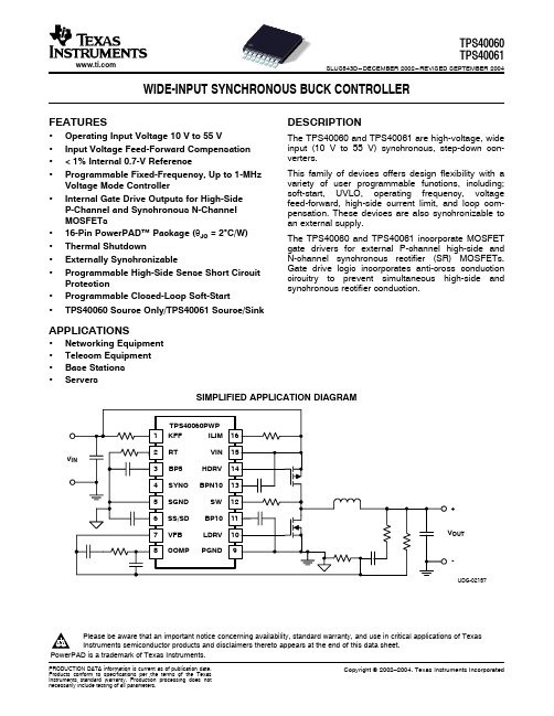
APPLICATIONS
• Networking Equipment • Telecom Equipment • Base Stations • Servers
SIMPLIFIED APPLICATION DIAGRAM
TPS40060PWP
1 KFF
ILIM 16
2 RT
VIN 15
VIN
3 BP5
Storage temperature
Lead temperature 1,6 mm (1/16 inch) from case for 10 seconds
TPS40060 TPS40061
60 V –0.3 V to 6 V –0.3 V to 60 V or VIN+5 V (whichever is less)
Frequency PWM ramp voltage(2) High-level input voltage, SYNC Low-level input voltage, SYNC Input current, SYNC Pulse width, SYNC
VRT RT voltage Maximum duty cycle
VIN VFB, SS/SD, SYNC
SW
VOUT IIN IOUT TJ Tstg
SW. transient < 50 ns
Output voltage range COMP, RT, KFF, SS
Input current
KFF
Output current
RT
Operating junction temperature range
PARAMETER
INPUT SUPPLY
LST400-中文操作手册
pasl npasnpawnawintwhitwhitehitmehtmeptmepemrpearpetauretaruretaruetruere notainotinon tgdortgoartgpargphariphaciphcdihcdiiscdipsdiplsaiplsyaplyalyay
•oLadoLadoaindaigndign&ign&g&& BBaBgaBgagaingigngignHignHogHopHopopeprespresresrs
ro42r042042V04AV0AVCAVC;AC±; C±;1- ±;51安±%51%5装1%55说%05明/056/0506–/006第/H06Hz08H,z页H,z,z, •sIssIsosIolsaIolstaeoltadeltadet4de4-d4-24-20-20m20mA0mAmOAOuAOtupOtuputuptutpwtuwtuitwthitwhiHthiHtAhHARHARTART7RT7T77
×637×7ihcniehcnsehcseh/se/1s/91/291×291×29×23×032×032×039×049×49494 •s5s5sC5Co5ConCofnigofnigufnigrufaigrubarubalerbaleRbleReleRleaRleyalesyalsya/sy/8s/8A/8Am8AmpAmpmpp
操作说明书OI/LST400-ZH Rev.A
LST400 超声波物位计
evevevevel el /l /l /O长/OO量pOppe程peen超ennnC声CCh波Chha物haanan位nnne/ne流el el Fl量Fl FloF计lololwowwwTTTrTrararanannsnsmsmsmmitititietetererrr
ASC-400中文操作手册

3.4 3.5
屏幕上部 (读取数据) – 功能……………………........................................................................................ 12 屏幕下部 (主显示)-功能…………………………........................................................................................ 12
TL400维修手册

TL400 液晶投影机 维修手册 联想集团有限公司 本手册中所包含的信息是联想集团有限公司于发行TL400 液晶投影机之前这些信息不提供任何专利许可。
联想集团有限公司保留修改这些信息的权利,恕不另行通知,并对这些信息不承担任何明确的或含蓄的声明或保证。
联想集团有限公司对任何使用这些信息而导致的任何损失或损坏,包括后果或特殊损害,甚至因联想集团有限公司的疏忽或其它过失而导致的损失或损坏,均不承担任何责任。
维修过程中,使用了“小心”标识以避免造成损坏。
1目录第1章联想TL400液晶投影机维修手册 (4)1.1简介 (4)本手册的组织结构 (4)1.2使用本维修手册 (5)在屏幕上移动页面 (5)第2章产品信息 (6)2.1产品概述 (7)2.2产品说明 (7)框图 (8)硬件平台描述 (9)操作系统 (12)2.3产品规格TL400 (13)投影灯 (14)投影镜头 (14)投影镜头的投影距离 (15)兼容性 (17)视频标准 (18)环境 (18)物理规格 (19)保修 (19)音频 (19)软件 (19)法规和安全性 (20)电气规格 (21)2.4控制功能 (22)控制类型 (22)投影机键区和遥控器 (22)投影机用户界面 (23)2.5I/O端口图解 (26)2第3章维修和维护投影机 (27)3.1安全指南 (28)基本规则 (28)电源 (28)特殊处理 (29)3.2投影机的故障排除 (30)故障诊断方法 (30)模块级替换法 (30)处理间歇性问题 (31)用户常见问题解答 (32)故障和解决方案 (32)电源和启动故障 (33)一般性图像质量问题——RGB、视频和徽标 (34)图像质量问题——仅RGB源 (35)图像质量问题——仅视频源 (36)音频故障 (36)遥控器故障 (37)键区故障 (37)风扇故障 (37)3.3清洁投影机 (38)3.4拆卸和更换前/顶盖 (39)拆卸和更换镇流器板 (41)拆卸和更换IO盖 (42)拆卸和更换投影灯组件 (43)拆卸和更换电源/镇流器板 (44)拆卸和更换风扇 (45)拆卸和更换引擎组件 (46)拆卸和更换引擎风扇 (47)3.5软件升级步骤 (48)3.6在投影机上执行功能性测试 (55)3.7键区操作和用户界面 (62)3第1章联想TL400液晶投影机维修手册1.1 简介本联机维修手册致力于帮助您维修TL400 液晶投影机。
LTC4006资料

UNITS V mA % % % % % % % µA µA V V µA mA
–0.8 –1.0 –4 –5 –60 –35 –15 15 –10 4.2 1 4.7 1.6 – 10 2
VBAT < 6V, VCSP – VBAT Target = 10mV 6V ≤ VBAT ≤ VLOBAT, VCSP – VBAT Target = 10mV TTOL Shutdown Battery Leakage Current UVLO Undervoltage Lockout Threshold Shutdown Threshold at SHDN SHDN Pin Current Operating Current in Shutdown Current Sense Amplifier, CA1 Input Bias Current Into BAT Pin CMSL CMSH CA1/I1 Input Common Mode Low CA1/I1 Input Common Mode High
ELECTRICAL CHARACTERISTICS
SYMBOL IQ VTOL ITOL PARAMETER DCIN Operating Range Operating Current Charge Voltage Accuracy Charge Current Accuracy (Note 3)
CONDITIONS Sum of Current from CLP, CLN , DCIN Nominal Values: 12.3V, 12.6V, 16.4V, 16.8V (Note 2) q VCSP – VBAT Target = 100mV
q
MIN 6
TYP 3
LT400手册

产品概述1编辑软件DP2002LT400操作方法3与PLC 的连接方法4LT400可编程文本显示器用户手册目录第一章产品概述1-1功能 ---------------------------------------------------------- 2 1-2一般规格 ------------------------------------------------------ 2 1-3各部分名称 ---------------------------------------------------- 2 1-4外形尺寸及安装方法 -------------------------------------------- 5第二章编辑软件DP2002-1 DP200概述 ---------------------------------------------------- 6 2-2-1 关于工程和画面 ------------------------------------------- 6 2-2-2 画面内容 ------------------------------------------------- 6 2-2-3 DP200 使用程式 ------------------------------------------- 6 2-2 编辑用户画面 -------------------------------------------------- 6 2-2-1 创建工程 ------------------------------------------------- 6 2-2-2 制作基本画面 --------------------------------------------- 8 2-2-3 DP200系统参数------------------------------------------- 9 2-2-4 文本 ----------------------------------------------------- 10 2-2-5 功能键(画面跳转)---------------------------------------- 12 2-2-6数据显示窗----------------------------------------------- 15 2-2-7数据设定窗----------------------------------------------- 18 2-2-8 指示灯--------------------------------------------------- 20 2-2-9功能键(开关量控制)------------------------------------- 23 2-2-10 棒形图-------------------------------------------------- 24 2-2-11 折线图 -------------------------------------------------- 25 2-2-12 报警列表 ------------------------------------------------ 26 2-3 保存工程 ------------------------------------------------------ 29 2-4 下载画面 ------------------------------------------------------ 29第三章LT400操作方法3-1 联机通讯 ----------------------------------------------------- 30 3-2 切换画面 ----------------------------------------------------- 30 3-3 系统口令 ----------------------------------------------------- 30 3-4 修改数据 ----------------------------------------------------- 32 3-5 开关量控制 --------------------------------------------------- 33第四章 PLC连接方法4-1 三菱FX系列 --------------------------------------------------- 34 4-2 西门子S7-200系列 --------------------------------------------- 35 4-2 欧姆龙C系列 -------------------------------------------------- 36 4-3 光洋SG系列 --------------------------------------------------- 37 4-4 施耐德NEZA系列 ----------------------------------------------- 38 4-5 台达DVP系列 -------------------------------------------------- 39 4-6 松下FP系列 --------------------------------------------------- 40 4-7 LG Master-K系列 ----------------------------------------------- 41第一章产品概述1-1功能LT400是可编程序控制器的小型人机界面,以文字或指示灯等形式监视、修改PLC内部寄存器或继电器的数值及状态.从而使操作人员能够自如地控制机器设备.LT400显示器有以下特长:通过编辑软件DP200在计算机上作画,自由输入汉字及设定PLC地址,使用串口通讯下载画面通讯协议和画面数据一同下载到显示器,无须PLC编写通讯程序对应PLC机种广泛,包括三菱FX系列、欧姆龙C系列、西门子S7-200系列、光洋SG系列等具有密码保护功能具有报警列表功能,逐行实时显示当前报警信息7个按键可被定义成功能键,可替代部分控制柜上机械按键自由选择通讯方式,RS232/RS422/RS485任选带背景光STN液晶显示,可显示24字符×4行,即12汉字×4行显示器表面IP65构造,防水、防油1-2一般规格2.环境条件操作温度 0~50℃保存温度 –10~60℃环境温度 20~85%(无凝露)耐振动 10~25Hz(X,Y,Z方向各30分钟2G)抗干扰电压噪声: 1000Vp-p周围空气无腐蚀性气体保护结构适合IP65F1-3 各部分名称LT400的正面除液晶显示窗之外,还有7个机械按键,触摸手感好、使用寿命长、安全可靠.7个按键除了具备基本功能外,还能被设定成特殊功能按键,直接完成画面跳转,开关量设定等功能。
1N4001S 1N4007S硅整流管规格书
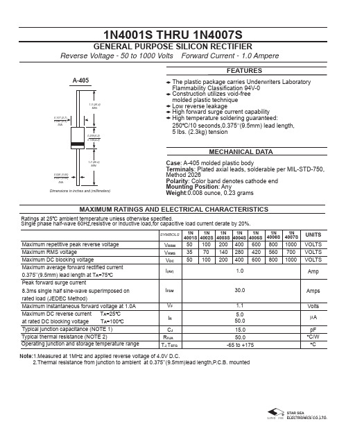
1N4001S THRU 1N4007SGENERAL PURPOSE SILICON RECTIFIERReverse Voltage - 50 to 1000 Volts Forward Current - 1.0 AmpereCase : A-405 molded plastic bodyTerminals : Plated axial leads, solderable per MIL-STD-750,Method 2026Polarity : Color band denotes cathode end Mounting Position : AnyWeight :0.008 ounce, 0.23 gramsThe plastic package carries Underwriters Laboratory Flammability Classification 94V-0Construction utilizes void-free molded plastic technique Low reverse leakageHigh forward surge current capability High temperature soldering guaranteed:250 C/10 seconds,0.375”(9.5mm) lead length,5 lbs. (2.3kg) tensionFEATURESMECHANICAL DATAMAXIMUM RATINGS AND ELECTRICAL CHARACTERISTICSA-405Dimensions in inches and (millimeters)50355010070100200140200400280400600420600800560800100070010001N4001S VOLTS VOLTS VOLTS SYMBOLSUNITS AmpAmps Volts V RRM V RMS V DC I (AV)I FSM V F 1.030.01.1Operating junction and storage temperature rangeMaximum repetitive peak reverse voltage Maximum RMS voltageMaximum DC blocking voltageMaximum average forward rectified current 0.375”(9.5mm) lead length at T A =75 C Peak forward surge current8.3ms single half sine-wave superimposed on rated load (JEDEC Method)Maximum instantaneous forward voltage at 1.0A Maximum DC reverse current T A =25 C at rated DC blocking voltage T A =100 C Typical junction capacitance (NOTE 1)Note:1.Measured at 1MHz and applied reverse voltage of 4.0V D.C.2.Thermal resistance from junction to ambient at 0.375”(9.5mm)lead length,P.C.B. mountedI R 5.050.0R θJA C J T J ,T STG50.015.0-65 to +175pF CA µTypical thermal resistance (NOTE 2)C/W 1N 4002S 1N 4004S 1N 4003S 1N 4005S 1N 4007S1N 4006S Ratings at 25 C ambient temperature unless otherwise specified.Single phase half-wave 60Hz,resistive or inductive load,for capacitive load current derate by 20%.RATINGS AND CHARACTERISTIC CURVES 1N4001S THRU 1N4007S0.6 0.8 1.0 1.2 1.4 1.50.01 0.1 1 10 1001001010.1REVERSE VOLTAGE,VOLTSt,PULSE DURATION,sec.FIG. 5-TYPICAL JUNCTION CAPACITANCEFIG. 6-TYPICAL TRANSIENT THERMAL IMPEDANCEFIG. 3-TYPICAL INSTANTANEOUS FORWARDCHARACTERISTICSNUMBER OF CYCLES AT 60 HzFIG. 2-MAXIMUM NON-REPETITIVE PEAK FORWARDFIG. 1- FORWARD CURRENT DERATING CURVEA V E R A G E F O R W A R D R E C T I F I E D C U R R E N T ,A M P E R E SI N S T A N T A N E O U S F O R W A R D C U R R E N T ,A M P E R E SJ U N C T I O N C A P A C I T A N C E ,p FP E A K F O R W A R D S U R G E C U R R E N T ,A M P E R E SINSTANTANEOUS FORWARD VOLTAGE,VOLTS1001010.10.01PERCENT OF PEAK REVERSE VOLTAGE,%FIG. 4-TYPICAL REVERSE CHARACTERISTICSI N S T A N T A N E O U S R E V E R S E C U R R E N T ,M I C R O A M P E R E ST R A N S I E N T T H E R M A L I M P E D A N C E ,C /WAMBIENT TEMPERATURE, C。
4066中文资料
Sine
Wave
5
VDD = 15V
Distortion
0
Frequency
VC = VDD = 5V, VSS = −5V RL = 10 kΩ,
0.
Response-Switch VIS = 5Vp-p, f= 1 kHz, (Figure 4)
1
“ON” (Frequency VC = VDD = 5V, VSS = −5V, RL = 1 kΩ,
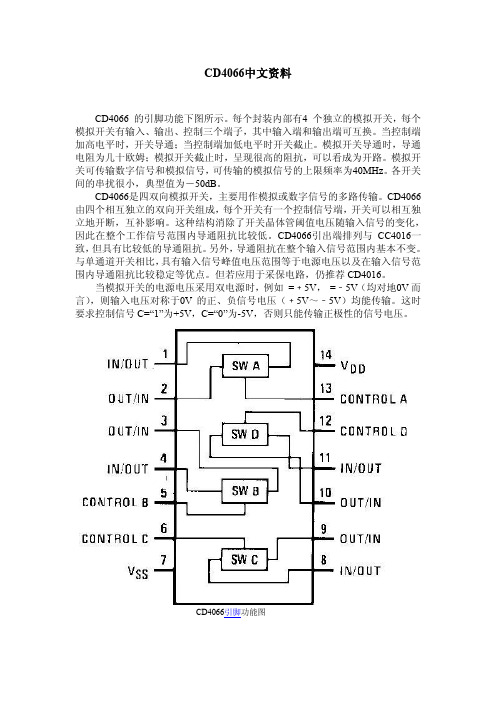
当模拟开关的电源电压采用双电源时,例如 =﹢5V, =﹣5V(均对地0V 而 言),则输入电压对称于0V 的正、负信号电压(﹢5V~﹣5V)均能传输。这时 要求控制信号 C=“1”为+5V,C=“0”为-5V,否则只能传输正极性的信号电压。
CD4066引脚功能图
内部方框图
Absolute Maximum Ratings 绝对最大额定值:
5
=50pF(Figure 6)
0
RL=1.0kΩ, CL=50pF, (Figure 7)VOS(f) = ½ VOS(1.0 kHz)
6. VDD = 5.0V
0
8. VDD = 10V
0
8. VDD = 15V
5
Signal
Input
CIS Capacitance 信 号
8.
输入电容
0
Signal
20
80 240
320
0
Δ“ON”
RL = 10kΩ to (VDD − VSS/2) VCC = VDD, VIS = VSS to VDD
ΔRO Resistance
VDD = 10V
10
N Between Any 2
LT4356HMS-1#PBF中文资料

–40°C to 125°C
Consult LTC Marketing for parts specified with wider operating temperature ranges. *The temperature grade is identified by a label on the shipping container. For more information on lead free part marking, go to: /leadfree/ For more information on tape and reel specifications, go to: /tapeandreel/
The LT®4356-1 surge stopper protects loads from high voltage transients. It regulates the output during an overvoltage event, such as load dump in automobiles, by controlling the gate of an external N-Channel MOSFET. The output is limited to a safe value thereby allowing the loads to continue functioning. The LT4356-1 also monitors the voltage drop between the VCC and SNS pins to protect against overcurrent faults. An internal amplifier limits the current sense voltage to 50mV. In either fault condition, a timer is started inversely proportional to MOSFET stress. If the timer expires, the FLT pin pulls low to warn of an impending power down. If the condition persists, the MOSFET is turned off.
1N4006G-T3中文资料

1N4001G – 1N4007G1.0A GLASS PASSIVATED STANDARD DIODESingle Phase, half wave, 60Hz, resistive or inductive load.For capacitive load, derate current by 20%.CharacteristicSymbol 1N 4001G 1N 4002G 1N 4003G 1N 4004G 1N 4005G 1N 4006G 1N 4007G UnitPeak Repetitive Reverse Voltage Working Peak Reverse Voltage DC Blocking Voltage V RRMV RWM V R 501002004006008001000V RMS Reverse VoltageV R(RMS)3570140280420560700V Average Rectified Output Current(Note 1) @T A = 75°C I O1.0ANon-Repetitive Peak Forward Surge Current 8.3ms Single half sine-wave superimposed on rated load (JEDEC Method)I FSM 30A Forward Voltage @I F = 1.0A V FM 1.0V Peak Reverse Current @T A = 25°C At Rated DC Blocking Voltage @T A = 100°C I RM 5.050µA Typical Junction Capacitance (Note 2)C j 8.0pF Typical Thermal Resistance Junction to Ambient (Note 1)R JA 50°C/W Operating Temperature Range T j -65 to +175°C Storage Temperature RangeT STG-65 to +175°CNote: 1. Leads maintained at ambient temperature at a distance of 9.5mm from the case2. Measured at 1.0 MHz and Applied Reverse Voltage of 4.0V D.C.WTE40608010012014016018000.20.40.60.81.0I ,A V E R A G E F O R W A R D R E C T I F I E D C U R R E N T (A )(A V )T ,AMBIENT TEMPERATURE (ºC)Fig.1Forward Current Derating CurveA C ,C A P A C I T A N C E (p F )j V ,REVERSE VOLTAGE (V)Fig.4T ypical Junction CapacitanceR 1.0101001.0101001.010100I ,P E A K F O R W A R D S U R G E C U R R E N T (A )F S M NUMBER OF CYCLES AT 60HzFig.3Max Non-Repetitive Peak Fwd Surge Current403020010500.60.8 1.0 1.2 1.4 1.60.010.11.0I ,I N S T A N T A N E O U S F O R W A R D C U R R E N T (A )F V ,INSTANTANEOUS FORWARD VOLTAGE (V)Fig.2Typical Forward CharacteristicsF 10MARKING INFORMATION TAPING SPECIFICATIONS6mmORDERING INFORMATIONProduct No.Package TypeShipping Quantity1N4001G-T3DO-415000/Tape & Reel 1N4001G-TB DO-415000/Tape & Box 1N4001G DO-411000 Units/Box 1N4002G-T3DO-415000/Tape & Reel 1N4002G-TB DO-415000/Tape & Box 1N4002G DO-411000 Units/Box 1N4003G-T3DO-415000/Tape & Reel 1N4003G-TB DO-415000/Tape & Box 1N4003G DO-411000 Units/Box 1N4004G-T3DO-415000/Tape & Reel 1N4004G-TB DO-415000/Tape & Box 1N4004G DO-411000 Units/Box 1N4005G-T3DO-415000/Tape & Reel 1N4005G-TB DO-415000/Tape & Box 1N4005G DO-411000 Units/Box 1N4006G-T3DO-415000/Tape & Reel 1N4006G-TB DO-415000/Tape & Box 1N4006G DO-411000 Units/Box 1N4007G-T3DO-415000/Tape & Reel 1N4007G-TB DO-415000/Tape & Box 1N4007GDO-411000 Units/Box1. Products listed in bold are WTE Preferred devices.2. Shipping quantity given is for minimum packing quantity only. For minimum order quantity, please consult the Sales Department.3.To order RoHS / Lead Free version (with Lead Free finish), add “-LF” suffix to part number above. For example, 1N4001G-TB-LF .Won-Top Electronics Co., Ltd (WTE) has checked all information carefully and believes it to be correct and accurate. However, WTE cannot assume any responsibility for inaccuracies. Furthermore, this information does not give the purchaser of semiconductor devices any license under patent rights to manufacturer. WTE reserves the right to change any or all information herein without further notice.WARNING : DO NOT USE IN LIFE SUPPORT EQUIPMENT. WTE power semiconductor products are not authorized for use as critical components in life support devices or systems without the express written approval.We power your everyday.Won-Top Electronics Co., Ltd.No. 44 Yu Kang North 3rd Road, Chine Chen Dist., Kaohsiung, Taiwan Phone: 886-7-822-5408 or 886-7-822-5410Fax: 886-7-822-5417Email: sales@Internet: 。
SMC6400B使用手册200942710010534[1]
![SMC6400B使用手册200942710010534[1]](https://img.taocdn.com/s3/m/7b649ce7524de518964b7dc1.png)
本手册版权归深圳市雷泰控制技术有限公司所有,未经雷泰 公司书面许可,任何人不得翻印、翻译和抄袭本手册中的任何内 容。 本手册中的信息资料仅供参考。 由于改进设计和功能等原因, 雷泰公司保留对本资料的最终解释权。内容如有更改,恕不另行 通知。
调试机器要注意安全!用户必须在机器中设计有效的安全保护装置,在 软件中加入出错处理程序。否则所造成的损失,雷泰公司没有义务或责任对 此负责。
SC400控制系统用户说明书
Version 1.4
深圳 市雷泰 控制技 术有 限公司
S HE NZ HE N LE AD TE CH C ON TR OL T EC HN OL OG Y CO ., L TD
-1-
©Copyright 2007 Leadtech Control Technology Co.,Ltd. All Rig h ts Re se r ve d . 版 权 说 明2 1.3 1.4 第二章 2.1
录
概述................................................................................................................................ - 1 产品概述......................................................................................................................... - 1 技术特性..................................................................................................
SCL-400仪表使用说明书
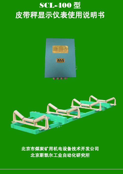
SCL-400型皮带秤显示仪表使用说明书北京市煤炭矿用机电设备技术开发公司北京斯凯尔工业自动化研究所序章功能及特征 (3)第一章各部名称及其功能 (4)序章功能及特征 (3)第一章各部名称及其功能 (4)1.1 前面板 (5)1.1.1显示屏 (5)1.1.2 状态指示灯 (6)1.1.3 按键 (6)第二章操作指南 (7)2.1 仪表上电自检 (7)2.2 显示切换 (7)2.3 参数设臵 (8)2.4 操作选择 (13)第三章电子皮带秤标定 (14)3.4 零点标定 (18)3.5 速度标定 (18)3.6 计量标定 (19)3.6.1 实物标定 (19)3.6.2 模拟标定 (20)3.6.3 模拟校验 (22)3.7影响标定误差的因素 (22)第四章包装、运输、贮存 (22)4.1产品包装符合铁路或汽运要求,包装箱外壳标明如下内容: (22)4.2 随同产品文件: (22)4.3 运输 (22)4.4 贮存 (22)第五章质量保证 (22)附录1 电子皮带秤基础知识23序章功能及特征作为皮带秤和皮带定量给料机的积算调节仪表SCL-400,是对皮带输送系统中的散状物料进行连续计量的理想设备,具有结构简单、称量准确,使用稳定、操作方便、维护量少等优点。
主要应用于冶金、电力、煤炭、矿山、港口、化工、建材等行业。
图1 SCL-400型电子秤仪表计量监控系统结构示意图特点:1)可靠性高采用了新型材料的非易失性存储器,保证了累计量、运行状态、各种参数值、设定值等重要数据可以存储长达100年,断电后不会丢失数据。
设计时,通过增加滤波器、模拟电路和逻辑电路通过光电耦合器完全隔离以及PCB布局时将高频区域、功率区域、数字区、模拟区分别处理等手段,提高了仪表的抗干扰能力,能通过4000V脉冲干扰测试。
2)具备多种通讯接口在仪表的主板上设计了通用型的通讯接口,可兼容我公司生产的点对点式及总线式调制解调器通讯板、485总线通讯板、CAN总线通讯板、以太网通讯板和无线射频通讯板。
ELT-400电磁场曝光级别测量器说明书

Safety Evaluation Within a Magnetic Field EnvironmentDirect evaluation of field exposure incomparison with major standards andregulations such as Directive 2013/35/EU forworkplacesAutomatic exposure evaluation for variouswaveforms in compliance with Weighted RMSand Weighted Peak methodsEliminates the overestimation thatoccasionally occurs with FFT-based evaluationUltra wide frequency range(1 Hz to 400 kHz)Wide measurement range up to 80 mT(dependent on type)IEC/EN 62311 and 62233 standard compliantincluding isotropic 100 cm² and 3 cm² probeThree-axis analog signal outputExposure Level Tester ELT-400t a b l i s h e d1981NSTS 0714-E0205O 1 / 8Subject to change without noticeNSTS 0714-E0205O 2 / 8Subject to change without noticeAPPLICATIONSThe ELT-400 is an innovative exposure level meter for measuring magnetic fields in the workplace and in public spaces. The model is designed for health and safety professionals in industry, the insurance business and service industries.The instrument can simply and precisely handle practically any level measurement required in the low and medium-frequency range. It is comparable to the sound level meters that are commonly used in the assessment of noise at the workplace.Production AreasThe ELT-400 is useful for checking fields caused by various manufacturing plant, including induction heating, melting and hardening equipment. Thanks to its extremely low frequency limit and high power capability, it can also be used to check most magnetic stirrers.Special demands often occur with machinery in production areas where non-sinusoidal signals are common, e.g. in industrial applications that use resistance welding machinery (pulse waveform, phase angle control) with traditional 50/60 Hz systems, as well as in newer medium-frequency switching units.General EnvironmentThe different types of electronic article surveillance systems generate complex fields in public spaces. Most electromagnetic and magneto acoustic gates operate within the frequency range of the ELT-400.EMC Test HouseThe magnetic fields generated by household appliances or other electrical devices have become the focus of increased attention. Some new standards such as IEC/EN 62233 describe how to investigate such products. The ELT-400 is the ideal measuring device when it comes to compliance with these standards. Benefits include the perfectly matched frequency range and implementation of the specified transfer function.The ELT-400 allows to greatly simplify the assessment process. With EXPOSURE STD (Shaped Time Domain) mode, the instrument achieves a new standard in simple but reliable measurement of magnetic fields, whether in straightforward or in very complex field environments. Industrial melting furnaceResistance welding machinery in operation Magneto acoustic gate used for product surveillanceNSTS 0714-E0205O 3 / 8Subject to change without noticeThe easily misinterpreted time-consuming measurements with aspectrum analyzer or scope are rendered obsolete. Detailed knowledgeabout the evaluation procedure or the field waveform or frequency is nolonger needed. The results are reliable, and speed and ease of use aresignificantly better than all traditional methods.BASIC OPERATIONThe ELT-400 covers the wide frequency range of 1 Hz to 400 kHz. Themeasurement range of the ELT-400 is far wider than the reference limitsof common guidelines. The instrument has an external isotropicmagnetic field probe with a 100 cm2cross-sectional area. This issuitable for standards-compliant measurement even in non-homogeneous fields. The ELT-400 has a rugged housing and is easy tooperate using only six buttons. The measurement result and theinstrument settings are clearly displayed on a backlit LCD panel.The optional probe extension cable is specially designed for lowinfluence on the frequency response and sensitivity of the instrument.The cable is a good choice in cases where the probe and instrumentmust be handled separately. Variants of the ELT-400 are available withdifferent operating mode combinations, e.g. “Exposure STD” or “FieldStrength”. Please refer to the Ordering Information section for details.EXPOSURE STD (SHAPED TIME DOMAIN) MODESignal-Shaped-Independent Field EvaluationIn EXPOSURE STD mode, the level of the magnetic (B) field is directlydisplayed as a “Percent of Standard” regardless of the signal shape andfrequency. The numeric result clearly reflects the current situation andthe remaining safety margin. The method employed can be compared tosound level meters that are commonly used to determine noise in theworkplace.The variation with frequency specified in the standard is normalized bymeans of an appropriate filter. Users no longer need to know thefrequency or the frequency-dependent limits. The standard is easilyselected by pressing just one button. Multi-frequency signals are just aseasy to measure as single frequencies.Compliance testing of household appliancesCoupling factors can be determined in compliancewith IEC/EN 62233 by use of the optional 3 cm2 probeNSTS 0714-E0205O 4 / 8Subject to change without noticeThe newer safety standards and guidelines also specify waveform-specific evaluation procedures. For example, stationary sinusoidal and pulsed fields are differentiated. With the ELT-400 the waveform is automatically taken into account. Users no longer need any knowledge about the waveform or the duty cycle. Measurements on pulsed signals are also possible. Different evaluation patterns are occasionally specified in the standard for certain pulse waveforms. These patterns (valid for all imaginable waveforms) are directly handled by EXPOSURE STD mode. This completely eliminates the need to analyze the waveform in the time domain using a scope.Even when faced with pulses that include DC fields, the EXPOSURE STD method provides valuable results. The ELT-400 covers all the signal components down to 1 Hz that are relevant in assessing such a situation.Occasionally both the RMS value and the peak value are critical for assessing exposure in the low-frequency range. Both detector types are provided (Weighted RMS and Weighted Peak), and are simultaneously activated in the default setting. Depending on the incoming signal and standard selected, the most suitable detector is automatically employed at all times. The necessary weighting factors are also taken into account. The detectors may also be selected independently for further interpretation of the signal.Detailed knowledge of the field, the test equipment and other auxiliary conditions is necessary to obtain insight into the degree of exposure when using traditional analysis instruments. The exposure level is derived through extensive calculation. Results can be easily misinterpreted or other problems may occur. For example, FFT spectrum analysis tends to overestimate results for the ICNIRP standard. The ELT-400 continuously monitors the field, and the results are constantly updated. Any change in the field, e.g. due to a power reduction, can be evaluated immediately.Proper evaluation in a personal safety context is achieved quickly and reliably using the STD technique. In Exposure STD mode the result is displayed directly as a percentage of the permitted limitExposure STD automatically sets the prescribeddetector applicable for the selected standardNSTS 0714-E0205O 5 / 8 Subject to change without noticeFIELD STRENGTH MODEBroadband Field Strength MeasurementsIf the field under test is essentially a single frequency component, broadband mode is also a good choice.The ELT-400 provides an ultra wideband, flat frequency response. The measurement range can handle extremely high field strength levels. Both detectors, RMS and Peak, are available for broadband measurement. The field strength result is displayed in “Tesla”.ACTIVE FIELD PROBEThree-Axis Analog Signal OutputFor scientific studies or advanced signal-shape / frequency analysis, a scope or an FFT analyzer can be connected to the analog output. The output signal ensures proper phase within the three axes and covers the full bandwidth of the instrument.The buffered output provides an adequate voltage swing to allow forsimple operation.Broadband measurement in “mT”with RMS detectorThe oscilloscope display shows the welding current when using the analog signal output of ELT-400aa Unless otherwise stated, these specifications apply fort the reference condition: ambient temperature 23±3 °C,relative air humidity 40 % to 60 %, continuous wave signal (CW) and RMS detectionb Depends on type; see Ordering Informationc Detection: Automatic according to selected standard, for IEC/EN 62233 based on ICNIRP limit valuesd Includes flatness, isotropy, absolute and linearity variations (frequency range: 1 Hz to 400 kHz or 10 Hz to 400 kHz).The uncertainty increases at the frequency band limits to ±1 dB based on the nominal frequency response.e For Frequency Range 10 Hz to 400 kHz and 30 Hz to 400 kHz only.NSTS 0714-E0205O 6 / 8Subject to change without noticea Unless otherwise stated, these specifications apply for the reference condition: ambient temperature 23±3 °C,relative air humidity 40 % to 60 %, continuous wave signal (CW) and RMS detectionb Depends on type, see Ordering Informationc Detection: Automatic according to selected standard, for IEC 62233 based on ICNIRP limit valuesd Includes flatness, isotropy, absolute and linearity variations (frequency range: 1 Hz to 400 kHz or 10 Hz to 400 kHz).The uncertainty increases at the frequency band limits to ±1 dB based on the nominal frequency response.e For frequency range 10 Hz to 400 kHz and 30 Hz to 400 kHz only.NSTS 0714-E0205O 7 / 8Subject to change without noticeNSTS 0714-E0205O 8 / 8 Subject to change without notice® Names and Logo are registered trademarks of Narda Safety Test Solutions GmbH and L3 Communications Holdings, Inc. – Trade names are trademarks of the owners.Narda Safety Test Solutions GmbH Sandwiesenstrasse 772793 Pfullingen, Germany Phone: +49 7121 9732 0 Fax: +49 7121 9732 790E-Mail:*************************** Narda Safety Test Solutions 435 Moreland RoadHauppauge, NY 11788, USA Phone: +1 631 231-1700 Fax: +1 631 231-1711E-Mail:*******************Narda Safety Test Solutions Srl Via Leonardo da Vinci, 21/23 20090 Segrate (Milano) - Italy Phone: +39 02 2699871 Fax: +39 02 26998700E-mail:**************************www.narda-sts.it。
7344-15SUGCS400-X6;中文规格书,Datasheet资料

Technical Data Sheet5.0mm Round Type LED Lamps7344-15SUGC/S400-X6█ Features :●Choice of various viewing angles ●Available on tape and reel.●Reliable and robust ●Pb free█ Descriptions :●The series is specially designed forapplications requiring higher brightness●The led lamps are available with different colors, intensities.█ Applications :●TV set ●Monitor ●Telephone ●Computer7344-15SUGC/S400-X6InGaNSuper GreenWater ClearEVERLIGHT ELECTRONICS CO.,LTD. http : // Rev.:1Page: 1 of 6Device Number :CDLE-734-115Prepared date:2005/4/18Prepared by:Hong Fa ChenBG0503087,R0501651Lens ColorPART NO.MaterialEmitted ColorNote: *1:Soldering tine ≦5 secondsEVERLIGHT ELECTRONICS CO.,LTD.http : // Rev.:1Page: 2 of 6Device Number :CDLE-734-115Prepared date:Prepared by:Hong Fa Chen2005/4/18Technical Data Sheet5.0mm Round Type LED Lamps7344-15SUGC/S400-X6Electro-Optical Characteristics (Ta=25℃)Symbol Min.Typ.Max.Unit VF I F =20mA / 3.4 4.0V IR V R =5V //50μA Iv I F =20mA 8000011000/mcd 2θ1/2I F =20mA /20/deg λp I F =20mA /525/nm λd I F =20mA /530/nm △λI F =20mA/35/nmEVERLIGHT ELECTRONICS CO.,LTD.http : // Rev.:1Page: 3 of 6Device Number :CDLE-734-115Prepared date:Prepared by:Hong Fa ChenPeak Wavelength 2005/4/18Dominant Wavelength Spectrum RadiationBandwidthLuminous Intensity Viewing Angle Parameter Condition Forward Voltage Reverse CurrentTechnical Data Sheet5.0mm Round Type LED Lamps7344-15SUGC/S400-X6█ Reliability test items and conditions:The reliability of products shall be satisfied with items listed below. Confidence level:97% LTPD:3%NOItemTest ConditionsSample Size FailureJudgment Criteria1Solder Heat TEMP : 260℃ ± 5 ℃76 PCSH : +100℃ 15min2Temperature Cycle∫ 5 min 76 PCS L : -40℃ 15min H : +100℃ 5min3Thermal Shock ∫ 10 sec 76 PCSL : -10℃ 5min4High TemperatureStorage TEMP : 100℃76 PCS5Low TemperatureStorage TEMP : -40℃76 PCSTEMP : 25℃I F = 20mA 7High Temperature /High Humidity85℃ / 85% RH76 PCSNote :Ivt:To test Iv value of the chip before the reliablility testIv:The test value of the chip that has completed the reliablility test U:Upper Specification Limit L: Lower Specification LimitEVERLIGHT ELECTRONICS CO.,LTD. http : // Rev.: 1Page: 5 of 6Device Number :CDLE-734-115Prepared by:Hong Fa ChenPrepared date:2005/4/18Test Hours/Cycle 10 SEC0/176 PCS 300 CYCLES 300 CYCLES 1000 HRS 0/10/10/1Iv≦Ivt*0.5or Vf≧U or Vf≦L Ac/Re 0/10/10/11000 HRS1000 HRS 1000 HRS6DC Operating LifeTechnical Data Sheet5.0mm Round Type LED Lamps7344-15SUGC/S400-X6EVERLIGHT ELECTRONICS CO.,LTD. http : //'Re1Page: 6 of 6 Device Number :CDLE-734-115 Prepared date:2005/4/18Prepared by:Hong Fa Chen分销商库存信息: EVERLIGHT7344-15SUGC/S400-X6。
色彩基础知识

色彩基础知识色彩基本知识一、色彩的形成1.认识色彩色彩作为视觉信息,无时无刻不在影响着人类的正常生活。
美妙的自然色彩,刺激和感染着人的视觉和心理情感,提供给人们丰富的视觉空间。
我们认识色彩基本上有以下途径:(1)日常生活中的接触(自然景色、环境设置、物品等)(2)对色彩的科学研究,色彩资料的收集、研制和创新。
(3)艺术类对色彩的艺术表现,如影视戏剧艺术、造型艺术、艺术家造诣的个性化表现。
对色彩的良好感觉,首先的前提条件是人健全的眼睛,因为认知色彩的唯一方式就是视觉,加上日积月累的生活经验、直觉,给认识色彩提供了生活物质的基本条件。
2.色与光没有光,惟一的感觉就是黑,我们什么也看不见。
那么,色与光是什么样的关系呢?从远古到17世纪以前,人类对色彩的认识只停留在感性认识上,仅仅通过视觉的观察与推测、判断。
真正对色彩的科学分析,是1666年,牛顿通过三梭镜分解出来的可见光谱开如的。
自然光投在垂直的白色立面上,出现一种连续的色带,相互渐次变化,呈现出红(Red)、橙(Orange)、黄(Yellow)、绿(Green)、青(ble-green)、蓝(blue)、紫(purple)七种色彩,我们通常称之为虹。
光是属于一定波长范围内的电磁辅身射,我们肉眼可以看到的仅仅是从400nm-700nm 这一极小的范围。
人们对这一范围内的电磁辅射最敏感,被称之为现光谱。
可见光谱的电磁辅射是以波浪的形式存在的,由波峰和波谷的重延续构成的。
波峰与波谷间的垂直距离为振幅,振幅的大小影响着光的强弱。
振幅越大,光量越强,反之变反之。
水平的直线为波长,它的长短会产生色相的变化。
波长最长的色,波长最短的是紫色。
波长和色相的关系如下:红色---780-610nm 橙色---610-590nm 黄色---590-570nm绿色---570-500nm 蓝色---500-450nm 紫色---450-380nm物体反射所有波长时呈现白色,物质吸收全部色光时则呈黑色。
