FX5545G0181V2T2中文资料
R500_中文版
可选择多种天线组 合使用,实现 Wi-Fi 的高可用性
两个 10/100/1000 Mbps 端口;一个配备 PoE
高增益定向天线单元,不仅可 提供信号增益,而且提供干扰 抑制,从而获得扩展的信号范 围、可靠性和高数据速率
所 有 ZoneFlex R500 智 能 Wi-Fi 接 入 点 均 集 成 软 件 控 制 型 PD-MRC( 极 化 分 集) 智 能 天 线, 可 提 供 高 达 4 dB 的 BeamFlex 额外信号增益和 10 dB 干扰抑制,可极大地增强 始终处于移动状态且不断变换方向的移动设备的性能。
借助 Smart/OS 实现先进的 WLAN 应用
与 Ruckus 智能 WLAN 控制器同时使用时, 每台 ZoneFlex R500 均可支持一系列增值应 用,诸如:访客网络、动态预共享密钥(动态 PSK)、热点身份认证、无线干扰检测等。借 助 Smart/OS,可创建多个 WLAN 并将其映射 到相同或不同的接入点或 VLAN。在集中托管的 配置下,ZoneFlex R500 可与各类认证服务器配合使用,如微 软活动目录、LDAP 和 RADIUS。
完成本地和远程管理
每台 ZoneFlex R500 均可以独立接入点身份通过基于 Web 的 GUI、使用 SNMP 或通过 Ruckus FlexMaster Wi-Fi 远程 管理系统进行管理。也可使用 Ruckus 智能 WLAN 控制器进行 本地管理。FlexMaster 是一种基 于 LINUX 的软件平台,使用行业标 准协议通过有线区域连接执行批量配 置、故障检测、监控和一系列故障排 除功能。企业可利用该控制器实现本 地管理和接入点控制、增加发射功率 控制和访客网络等增值服务。
2SJ554中文资料
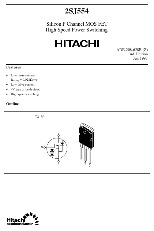
–3 V
–20
–10
–2.5 V
–2 V
0
–2 –4 –6 –8 –10
Drain to Source Voltage V DS (V)
Drain Current I D (A)
Typical Transfer Characteristics –50
V DS = –10 V 1VMTF5FTU –40
Drain to Source Voltage V DS (V)
5
2SJ554
Reverse Drain Current I DR (A) Repetitive Avalanche Energy E AR (mJ)
Reverse Drain Current vs.
Source to Drain Voltage –50
E Note3 AR
Channel dissipation
Pch Note2
Channel temperature
Tch
Storage temperature
Tstg
Note:
1. PW ≤ 10µs, duty cycle ≤ 1 % 2. Value at Tc = 25°C 3. Value at Tch = 25°C, Rg ≥ 50 Ω
1000 500 200
Switching Characteristics
t d(off) tf
100
tr
50
20
10 –0.1 –0.3
t d(on)
V GS = –10 V, V DD = –30 V PW = 5 µs, duty <= 1 %
–1 –3 –10 –30 –100
Drain Current I D (A)
ADL5542 RF IF增益模块说明书
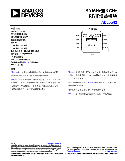
ADI 中文版数据手册是英文版数据手册的译文,敬请谅解翻译中可能存在的语言组织或翻译错误,ADI 不对翻译中存在的差异或由此产生的错误负责。
如需确认任何词语的准确性,请参考ADI 提供的最新英文版数据手册。
50 MHz 至6 GHz RF/IF 增益模块ADL5542Rev. BDocument Feedback Information furnished by Analog Devices is believed to be accurate and reliable. However , no responsibility is assumed by Analog Devices for its use, nor for any infringements of patents or other rights of third parties that may result from its use. Speci cations subject to change without notice. No license is granted by implication or otherwise under any patent or patent rights of Analog Devices. T rademarks and registered trademarks are the property of their respective owners.One Technology Way, P.O. Box 9106, Norwood, MA 02062-9106, U.S.A. Tel: 781.329.4700 ©2007–2013 Analog Devices, Inc. All rights reserved. Technical Support 功能框图2GND 7GND1RFIN 8RFOUT3GND 6GND4CB 5VPOSINPUT MATCHOUTPUT MATCHBIAS CONTROL ADL554206879-001图1.产品特性固定增益:20 dB 工作频率高达6 GHz 输入/输出内部匹配50 Ω集成偏置控制电路输出IP3 46 dBm (500 MHz)40 dBm (900 MHz)1 dB 输出压缩:20.6 dB (900 MHz)噪声系数:3 dB (900 MHz)5 V 单电源供电小尺寸8引脚LFCSP 封装与15 dB 增益的ADL5541引脚兼容1 kV ESD(1C 类)概述ADL5542是一款宽带20 dB 线性放大器,工作频率高达6 GHz ,可用于各种有线电视、蜂窝和仪器仪表设备。
Inspiron 5545 笔记本电脑使用说明书
3 摄像头
您可通过摄像头进行视频聊天、拍摄照片和摄制视频。
4 右侧麦克风
提供高品质数字声音输入以进行录音和语音呼叫等。
视图
尺寸和重量
高度: 触摸屏 非触摸屏
宽度 厚度 重量:
触摸屏 非触摸屏
规格
22 毫米(0.87 英寸) 21.80 毫米(0.86 英寸) 380.40 毫米(14.98 英寸) 259 毫米(10.20 英寸)
存储 –40°C 至 65°C(–40°F 至 149°F)
0% 至 95%(无冷凝) 1.30 GRMS 160 G‡
–15.2 米至 10,668 米 (–50 英尺至 35,000 英尺)
尺寸和重量
系统信息
内存
端口和接口
通信
视频
音频
存储
介质卡读取器
显示屏
键盘
摄像头
触摸板
电池
电源适配器
计算机环境
2.38 千克(5.25 磅) 2.18 千克(4.81 磅) 注:便携式计算机ss重量视订购配置和制造差异而有所不同。
尺寸和重量
系统信息
内存
端口和接口
通信
视频
音频
存储
介质卡读取器
显示屏
键盘
摄像头
触摸板
电池
电源适配器
计算机环境
视图
系统信息
计算机型号 处理器 芯片组
规格
Inspiron 5545 • 配置 Radeon R5 显卡的 AMD A8-7100 APU • 配置 Radeon R6 显卡的 AMD A10-7300 APU AMD A76M FCH
触摸板
电池
电源适配器
计算机环境
mil-dtl-5541f中文版
MIL -DTL - 5541F铝和铝合金的化学转化膜1.范围范围。
此规格涉及通过与表面爲铝和铝合金的化学转化材料反应而组成的化学转化膜。
分类。
化学转化膜有如下类型和等级。
类型。
化学转化膜有如下类型(见:类型I—包含六价铬的组成物类型II—无六价铬的组成物等级。
通过于铝和铝合金化学反应贰组成的材料有如下等级(见和)等级1A—爲最大限度保护防止喷涂的或者未喷涂处的腐蚀、等级3—爲保护防止需低电性阻值处的腐蚀2. 适用文件大意:此部分所列文件在本说明的第三和第四部分都有详细列明。
本部分不包含此说明中其他章节所引用的文件,推荐的附加信息文件以及用作事例的文件。
爲确保此清单的完整性已作出很多努力,文件使用者应注意,必须满足章节3或4引用文件的要求,不管这些文件有没有在此列明。
政府文件规格和标准。
以下规格和标准组成本文件的一部分。
除非特别指定,这些文件的问题引用在恳请或合同中。
联邦标准FED-STD-141--- 喷涂、油漆、涂漆和其他相关材料:检验、抽验和测试的方法国防部标准MIL-PRF-23377 --- 涂底漆:环氧基树脂,高固形化MIL-DTL-81706--- 用于涂覆铝及铝合金的化学转化膜MIL-PRF-85582--- 涂底漆:环氧基树脂,waterborne( 这些文件的副本可以在网站或者在线查看,或者也可以从位于PA19111-5094费城4D大厦700罗宾逊大街的标准文件预定服务台索取)非政府出版物。
以下规格和标准组成本文件的一部分。
除非特别指定,这些文件的问题引用在恳请或合同中。
美国材料试验协会ASTM-B117 ---- 盐雾试验仪器操作ASTM-D3359--- 胶带附着力测试(这些文件副本可以从位于PA19428-2959 ,west conshohocken, ASTM 获得或者从网站了解)美国质量协会(ASQ)ASQ-Z --- 通过属性进行程序,抽样及台板检验(此文件副本可从位于美国密尔沃基市的美国质量协会获得或从网站了解到。
Genuinetek蜂易达手机信号放大器选型指南
Genuinetek蜂易达手机信号放大器选型指南家庭用户信号不好存在多种情况,根据不同情况,应选用不同的手机信号放大器。
针对不同情况有不同的解决方案,不可一刀切。
底层小区信号差室外街道有较好的信号,室内信号较差,这个是一般的情况,主要是周边的建筑把基站的信号挡住了造成的。
这种情况是很常见的,可以加装Genuinetek蜂易达FX-Std系列信号放大器解决。
农村、郊区信号差室外有微弱信号,室内基本没有信号,信号差是由于农村、郊区基站不够密集,有些地方距离基站较远,造成了信号微弱。
应选用TX侧输出功率较高,增益较大的FX-HS系列提高最大传输距离。
大型厂房、别墅信号差室外街道有较好信号,室内基本没有信号,信号差是由于别墅、厂房的房间里面的钢筋混凝土很难被900Mhz左右频率的手机信号穿过,信号被挡住了,应选用蜂易达RX侧最大输出功率较高的FX-Pro提高室内覆盖面积。
高层信号差高层的手机信号差的原因和以上几点都不同,其实高层的手机信号并不差,那为什么会仍然打不通电话呢?主要是因为高层可以接收到附近好几个基站传过来的信号,然而因为没有阻挡,所以信号强度也差不多,于是手机就会在几个基站之间频繁地切换,这就是所谓的“乒乓效应”;另外,手机还有可能会收到非相邻的基站的信号,由于手机只能在相邻的基站间进行切换,就会造成其实有一个更好信号的基站的信号手机能收到,却由于基站不相邻无法切换过去,造成所谓的“孤岛效应”。
据介绍,乒乓效应和孤岛效应是目前移动通信的难题,加装第二代的蜂信通手机信号放大器高层版可以有效改善,其原理和解决方案也跟上述情况不同。
乒乓效应会造成手机频繁切换经常掉线,孤岛效应会造成手机脱网。
Genuinetek 蜂易达的FX-Pro可以有效解决乒乓效应和孤岛效应。
越区切换因为越区切换不成功也会造成手机掉线。
移动的运营商是通过基站和手机发送电磁波通信而为用户服务的。
然后一般基站都是蜂窝状的,覆盖范围有限,在一个较大的区域内有可能会同时有几个不同的基站。
wifi 无线SIP电话机--飞音时代简介
产品性能
� 通过多家海外运营商的入网测试并取得批量应用,包括 KT (Korean Telecom), KCT, LG Telecom,SK Telecom等 � 优秀的语音质量和长时间 工作稳定性。
� � - G.729 PAMS value > 4.0 - G.711 PAMS value > 4.3
处理外销业务2009主力产品g501推出产品设计向mipscpu平台迁徙g501通过韩国移动运营商skt测试开始进入批量销售voip电话机产品ip300ip500获得韩国政府tta安全认证并开始进入批量销售飞音voipiad产品合计销售超过100万台北京飞音时代技术有限公司顺利通过国家高新技术企业复审2010推出无线voip解决方案包括支持无线的voipiad产品及wifiphone产品在深圳设立深圳爱斯瑞科科技有限公司负责硬件产品的设计及外协厂管理飞音voip终端产品进入印度市场2011voip电话机产品ip6xx系列ip652ip622ip542n推向市场并在俄罗斯批量应用韩国运营商kct定制ieee80211n无线路由器通过bmt测试开始批量销售支持wifi的桌面式voip电话ip542n获得市场青睐北京飞音时代获得第一份发明专利授权专利号
重点产品介绍-G502N
• 采用低成本的1T1R无线路由器芯片RT5350实现,CPU 内核为MISP24KEc 360MHz主频 • 支持2路 FXS 接口;满足双路同时工作时G.729 PESQ 大于4.0 • 综合性能高于CISCO 同类产品 SPA2102 • 得益于飞音强大的软件DSP设计能力,我们得以推出此款产品;此架构在1~2端口 IAD 设备上具有绝对性价比优势;
北京飞音时代技术有限公司
2012年版本 David Huang
AD5541JR中文资料
a
5 V, Serial-Input Voltage-Output, 16-Bit DACs
AD5541/AD5542
FEATURES Full 16-Bit Performance 5 V Single Supply Operation Low Power Short Settling Time Unbuffered Voltage Output Capable of Driving 60 k⍀
Zero Code Temperature Coefficient AD5542
Bipolar Resistor Matching
Bipolar Zero Offset Error
Bipolar Zero Temperature Coefficient
± 0.5 ± 1.0
± 0.5 ± 2.0
± 0.5 ± 4.0
Unipolar Operation AD5542, Bipolar Operation
LOGIC INPUTS
Input Current
VINL, Input Low Voltage VINH, Input High Voltage Input Capacitance3 Hysteresis Voltage3
AGND
REFF
REFS CS
LDAC SCLK
DIN
AD5542
RINV
CONTROL LOGIC
DGND VDD RFB
16-BIT DAC
16-BIT DATA LATCH SERIAL INPUT REGISTER
DGND
RFB INV VOUT AGNDF
AGNDS
PRODUCT HIGHLIGHTS 1. Single Supply Operation.
F2X16 V2系列IP MODEM使用说明书
F2X16V2系列IP MODEM 使用说明书此说明书适用于下列型号产品:客户热线:400-8838-199电话:+86-592-6300320传真:+86-592-5912735网址:地址:厦门集美软件园三期A06栋11层F2X16V2系列IP MODEM使用说明书文档版本密级V1.0.2产品名称:F2X16V2共31页型号产品类别F2116V2GPRS IP MODEM F2A16V2LTE IP MODEM F2C16V2Cat.1IP MODEM文档修订记录日期版本说明作者2020-02-24V1.0.0初建ZDM 2020-04-16V1.0.1更新输入电源范围和产品图片ZDM 2020-05-12V1.0.2增加F2C16型号ZCL2/31著作权声明本文档所载的所有材料或内容受版权法的保护,所有版权由厦门四信通信科技有限公司拥有,但注明引用其他方的内容除外。
未经四信公司书面许可,任何人不得将本文档上的任何内容以任何方式进行复制、经销、翻印、连接、传送等任何商业目的的使用,但对于非商业目的的、个人使用的下载或打印(条件是不得修改,且须保留该材料中的版权说明或其他所有权的说明)除外。
商标声明Four-Faith、四信、、、均系厦门四信通信科技有限公司注册商标,未经事先书面许可,任何人不得以任何方式使用四信名称及四信的商标、标记。
3/31/314注:不同型号配件和接口可能存在差异,具体以实物为准。
目录第一章产品简介 (6)1.1产品概述 (6)1.3工作原理框图 (7)1.4产品规格 (8)第二章安装 (10)2.1概述 (10)2.2开箱 (10)2.3安装与电缆连接 (10)2.4电源说明 (13)2.5指示灯说明 (13)第三章参数配置 (14)3.1配置连接 (14)3.2参数配置方式介绍 (14)3.3参数配置详细说明 (14)3.3.1配置工具运行界面 (15)3.3.2设备上电 (16)3.3.4中心服务 (22)3.3.5串口 (23)3.3.6无线拔号 (24)3.3.7全局参数 (26)3.3.8设备管理 (27)3.3.9其它功能项 (28)第四章数据传输试验环境测试 (29)4.1试验环境网络结构 (29)4.2测试步骤 (29)5/316/31第一章产品简介1.1产品概述F2X16V2系列IP MODEM 是一种物联网无线数据终端,利用公用蜂窝网络为用户提供无线长距离数据传输功能。
点对点无线开关量采集用户手册说明书
在各种工业及行业应用中,经常需要采集各种开关量信号。
在工程实施过程中,很多时候,信号离监控主机的距离很远,需要布很长的信号线,或者布线不方便。
方竹电子推出了无线开关量采集模块,非常方便得解决了这个问题,实现无线的远程采集,降低了工程实施难度,又节约了成本。
该开关量采集方式由无线开关量采集模块和无线开关量输出模块组成。
原来的信号端接无线开关量采集模块,远端的主机系统接无线开关量输出模块,中间RF 无线传输;由于输出的仍然是开关量信号,因此对于用户来说,感觉只是将远处的采样设备搬到了近处而已,原有监控系统不需要做任何改动,却省却了布线。
1. 系统说明1.1. 系统框架无线开关量采集系统框架图注意:在P2P 使用的系统中,DO 模块作为无线网关使用;DI 作为无线终端设备。
以下说明书中的无线网关指DO 模块,终端设备指DI 模块。
1.2. 产品选型型号 类型FZ4050-C6 RF 无线开关量采集模块,支持干/湿节点输入 FZ4051-C6 RF 无线开关量输出模块,有源集电极开路输出(OC 门输出)FZ4060-C6RF 无线开关量输出模块,无源继电器输出P2P 使用:FZ4050开关量采集模块←→FZ4051开关量输出模块;FZ4050开关量采集模块←→FZ4060继电器输出模块。
1.3. 性能指标FZ4050为6通道隔离数字量输入模块,支持干/湿节点输入,P2P 无线通信。
FZ4051为6通道数字量输出模块,P2P 无线通信。
FZ4060为4通道继电器输出模块,P2P 无线通信。
性能指标无线性能无线协议FZMacPRO无线频段 433MHz ,ISM 全球免费频段 组网方式P2P通信距离≥1800米@2400bps(空旷环境)通用性能通信协议 MODBUS-RTU 串口性能 默认9600-8-N-1,可设 供电 8~38VDC 功耗 0.3W@12VDC外壳 钣金101.1mm ×80.4mm ×25.5mm 安装方式 壁挂(或导轨,选配)安装工作环境 -10~65℃;0%RH~90%RH (非结露) 存储条件 -20~80℃;0%RH~90%RH (非结露)FZ4050开关量输入通道数 6 输入电平干节点逻辑电平0:开 逻辑电平1:关(接地)湿节点逻辑电平0:+3 Vmax 逻辑电平1:+10V ~ 25VFZ4060继电器输出 通道数 4路A 型负载驱动 5A @30VDC ,5A@250VAC 开关时间继电器接通时间(典型):3毫秒 继电器断开时间(典型):1毫秒FZ4051开关量输出通道数 6负载驱动5~40V 集电极开路输出(200mA 最大负载电流)备注:1、干节点:无源开关,具有闭合和断开的2种状态;2个接点之间没有极性,可以互换。
2SC5548A资料
TOSHIBA Transistor Silicon NPN Triple Diffused Type2SC5548AHigh Voltage Switching Applications Switching Regulator Applications DC-DC Converter Applications• High speed switching: t r = 0.5 μs (max), t f = 0.3 μs (max) (I C = 0.8 A) • High collector breakdown voltage: V CEO = 400 V • High DC current gain: h FE = 40 (min) (I C = 0.2 A)Absolute Maximum Ratings (Ta = 25°C)Characteristics Symbol Rating UnitCollector-base voltage V CBO 600 V Collector-emitter voltage V CEO 400 V Emitter-base voltage V EBO 7 VDC I C 2Collector current Pulse I CP 4ABase current I B 0.5 A Ta = 25°C 1.0 Collector powerdissipationTc = 25°CP C15WJunction temperature T j 150 °C Storage temperature rangeT stg−55 to 150°CNote: Using continuously under heavy loads (e.g. the application of hightemperature/current/voltage and the significant change in temperature, etc.) may cause this product to decrease in the reliability significantly even if the operating conditions (i.e. operating temperature/current/voltage, etc.) are within the absolute maximum ratings.Please design the appropriate reliability upon reviewing the Toshiba Semiconductor Reliability Handbook (“Handling Precautions”/Derating Concept and Methods) and individualreliability data (i.e. reliability test report and estimated failure rate, etc).Unit: mmJEDEC ― JEITA―TOSHIBA 2-7B1AWeight: 0.36 g (typ.)JEDEC ― JEITA―TOSHIBA 2-7J1A Weight: 0.36 g (typ.)Electrical Characteristics (Ta = 25°C)Markinglead (Pb)-free package orlead (Pb)-free finish.B a s e -e m i t t e r s a t u r a t i onv o l t a g e V B E (s a t )(V )Collector-emitter voltage V CE (V)I C – V CEC ol l ec t o r c u r r e n t IC (A )Collector current I C (A)h FE – I CD C c u r r e n t g a i nh F ECollector current I C (A)V CE (sat) – I CC o l l e c t o r -e m i t t e r s a t u r a t io n vo l t a g e V C E (s a t )(V )Collector current I C (A)V BE (sat) – I CBase-emitter voltage V BE (V)I C – V BEC ol l e c t o r c u r r e n t I C (A )C o l l e c t o r po w e rd i s s i p a t i o n P C (W )Ambient temperature Ta (°C)P C – Ta2 4 6 8 100.0010.0030.010.030.1 0.3 1 30.010.1 0.3 30.03 1r th – t wT r a n s i e n t t h e r m alr esi s t a n c e rt h(°C /W )Collector-emitter voltage V CE (V)Safe Operating AreaC olle c to rcu rr e ntI C(A )Pulse width t w (s)Collector current I C (A)Switching Characteristics – I CS w i t c h i n g t i m e (μs )0.00110000.01 0.1 1 10 100100 100010 30RESTRICTIONS ON PRODUCT USE20070701-EN •The information contained herein is subject to change without notice.•TOSHIBA is continually working to improve the quality and reliability of its products. Nevertheless, semiconductor devices in general can malfunction or fail due to their inherent electrical sensitivity and vulnerability to physical stress. It is the responsibility of the buyer, when utilizing TOSHIBA products, to comply with the standards of safety in making a safe design for the entire system, and to avoid situations in which a malfunction or failure of such TOSHIBA products could cause loss of human life, bodily injury or damage to property.In developing your designs, please ensure that TOSHIBA products are used within specified operating ranges as set forth in the most recent TOSHIBA products specifications. Also, please keep in mind the precautions and conditions set forth in the “Handling Guide for Semiconductor Devices,” or “TOSHIBA Semiconductor Reliability Handbook” etc.• The TOSHIBA products listed in this document are intended for usage in general electronics applications (computer, personal equipment, office equipment, measuring equipment, industrial robotics, domestic appliances, etc.).These TOSHIBA products are neither intended nor warranted for usage in equipment that requires extraordinarily high quality and/or reliability or a malfunction or failure of which may cause loss of human life or bodily injury (“Unintended Usage”). Unintended Usage include atomic energy control instruments, airplane or spaceship instruments, transportation instruments, traffic signal instruments, combustion control instruments, medical instruments, all types of safety devices, etc.. Unintended Usage of TOSHIBA products listed in his document shall be made at the customer’s own risk.•The products described in this document shall not be used or embedded to any downstream products of which manufacture, use and/or sale are prohibited under any applicable laws and regulations.• The information contained herein is presented only as a guide for the applications of our products. No responsibility is assumed by TOSHIBA for any infringements of patents or other rights of the third parties which may result from its use. No license is granted by implication or otherwise under any patents or other rights of TOSHIBA or the third parties.• Please contact your sales representative for product-by-product details in this document regarding RoHS compatibility. Please use these products in this document in compliance with all applicable laws and regulations that regulate the inclusion or use of controlled substances. Toshiba assumes no liability for damage or losses occurring as a result of noncompliance with applicable laws and regulations.。
FX5545G0183V4T2中文资料
VishayLow Profile 3mm DC/DC Buck Converter0.8V to 4.5V*, 3A with 380W/in3 Power DensityEfficiency up to 95%FEATURES•Fully integrated DC/DC converter•Advanced development of FX5545G305•High efficiency over large load range•100% duty cycle•Power density - more than 380W/inch3•1µA shutdown current•2.5V to 6V input range (1Li+ and 3-cell NiCd or NiMH cells)•0.8V to 4.5V* output voltage•Programmable PWM/PSM controls•Low output ripple•BGA construction•Temperature range: - 40°C to + 85°C•No external components required•Output power 10W•Maximum current 3A•Low profile*Note: For higher putput voltage please consult factory atFunctionPAK@The DC/DC converter is a programmable topology synchronized Buck converter for today’s continuous changing portable electronic market. The DC/DC converter provides flexibility of utilizing various battery configurations and chemistries such as NiCd, NiMH, or Li+ with an input voltage range of 2.5V to 6V. An additional flexibility is provided with topology programmability to power multiple loads such as power amplifiers, microcontrollers, or baseband logic IC’s. For ultra-high efficiency, converters are designed to operate in synchronous rectified PWM mode under full load while transforming into externally controlled The DC/DC converter is available in 20-ports BGA package. In order to satisfy the stringent ambient temperature requirements, the DC/DC converter is designed to handle the industrial temperature range of - 40°C to + 85°C.APPLICATION•Cordless phones, PDAs and others•Supply voltage source for low-voltage chip sets•Point of Load (POL) applications such as drivers for FPGA’s, microprocessors, DSP’s amplifiers, etc.•Portable computers•Battery back-up supplies•CamerasORDERING INFORMATIONFX5545G008FUNCTIONSIZECIRCUIT IDENTIFIER - G008 or G018OUTPUT VOLTAGE - Example: 1.2V should be written as 1V2 as the V indicates the decimal point or ADJ for adjustable version - self selectable output voltage. G018ADJ is only available in the adjustable version for Vout = 0.9V - 1.3V. For design considerations please see ANF110PACKAGING - B1 = 10pcs in bulk; B5 = 50pcs in bulk; T1 = 13” reel; T2 = 7” reel.For lead (Pb)-free solder please add E2 suffix.VishayDIMENSIONS in inches [millimeters]L0.58 ± 0.01[14.7 ± 0.25]W0.48 ± 0.01[12.2 ± 0.25]A0.1 ± 0.01[2.54 ± 0.25]B0.09 ± 0.01[2.29 ± 0.25]C0.09 ± 0.01[2.27 ± 0.25]T0.126 max[3.2 max]Ball Diameter0.03 ± 0.001[0.762 ± 0.025]/doc?10119For adjustable version please refer to Self Selectable Output Voltageapplication note which is available at /doc?10116**Note: if not used must be connected ti Vin.***Note: N/C - If the output voltage is 0.9V and higher. For outputvoltage of 0.8V connect Vref to MCL4448 (Vishay RF PIN Diode).BOTTOM SIDEPIN CONFIGURATION*PIN CONNECTION1, 2SD3, 7SYNC**4, 8Vref***5, 9Vin6, 10PWM/PSM11, 12N/C13, 17GND14, 18Vout15, 19N/C16, 20GNDPin Configuration for Vo = 0.8V Pin Configuration for Vo = 0.9V - 4.5VRECOMMENDED PAD PATTERN in inches [millimeters]A D F0.1 ± 0.01[2.54 ± 0.25]0.03 ± 0.001[0.8 ± 0.02]0.02 ± 0.001[0.5 ± 0.02]TAPE AND REELSee Tape and Reel Information - T ype BVishay*Note: W D = Power DissipatedSTANDARD ELECTRICAL SPECIFICATIONSPARAMETER UNITCONDITIONMINTYPMAX InputVoltage Range V DC2.56Quiescent Current µAPSM mode 200Soft Start Time ms T SS for Vout = 3.3V 4T SS for Vout = 1.2V 2.6SD, PWM/PSM,SYNC Logic High V V H 2.4Logic Low VV L 0.8Normal Mode µA I DD 750PSM ModeµA I DD 250Shutdown Mode µAI DD1Shutdown Time ms T SS for Vout = 3.3V 4T SS for Vout = 1.2V 0.6Insulation T est Voltage V AC 60Hz 60sec 750ResistanceΩV ISO = 500 V DC 1 x 10¹¹Leakage Current nA V ISO = 500 V DC5Output Power W 10VoltageV DC 0.8 to 4.5Voltage T olerance%For Vout = 0.9V and above (using external diode BAR065V forVout = 0.9V up to 1.3V) at 25°C Ambient T emp.- 3+3%For Vout = 0.8V up to 1.3V using external diode MCL4448 at25°C Ambient T emp.- 5+5T emp. Coefficient %/°C 0.15Ripple and Noise mVpp DC to 20 MHz80GeneralPackage Weight gr. 1.4Oscillator Frequency KHz 400SYNC Range F SYNC /F OSC1.2 1.5Temperature Operation °C - 40+ 85Storage °C - 55+ 125Operating Junction T emp.°C T j 150Thermal Impedance °C/W D *θJA82Rise Time Rise Time (PWM mode): Vin = 6V; Vout = 3.3V; lout = 3A Fall TimeFall Time (PWM mode): Vin = 6V; Vout = 3.3V; lout = 3AVishayPWM MODEVout Vs. lout*Vin = 4.0VVout Vs. Vin*Δ Temp Vs. lout*Above 25°C Ambient Temperature Vin = 6.0V; Vout = 3.3VEfficiency Vs. Lout*Vout = 3.3AVout Vs. lout*Vin = 4.0VVout Vs. Vin*Vin = 6VΔ Temp Vs. lout*Above 25°C Ambient Temperature Vin = 6.0V; Vout = 1.2VEfficiency Vs. lout*Vin = 4.0V; Vout = 1.2V* Note: Measurements were taken with Power supply: ZUP 20-40 from Nemic Lambda; Electronic load: 6063B from Agilent; Multimeter Fluke 45VishayVout Vs. lout* Vin = 4.0V Vout Vs. Vin*Vin = 6VEfficiency Vs. lout*Vin = 4.0V; Vout = 3.3VVout Vs. lout*Vin = 4.0VVout Vs. Vin*Efficiency Vs. lout*Vin = 4.0V; Vout = 1.2VPSM MODE* Note: Measurements were taken with Power supply: ZUP 20-40 from Nemic Lambda; Electronic load: 6063B from Agilent; Multimeter Fluke 45。
FIFE-500 快速入门手册说明书
FIFE-500Quick-Start ManualMI 2-263 1 BINTRODUCTION ........................................................................................ 1-1 Copyright information ............................................................................................ 1-1 General information ............................................................................................... 1-1 Language ............................................................................................................... 1-1FEATURES ................................................................................................. 2-1 Display definitions ................................................................................................. 2-1 Button functions and definitions ............................................................................ 2-3 Status bar definitions ............................................................................................. 2-4OPERATION .............................................................................................. 3-1 System setup ......................................................................................................... 3-1 Auto setup configuration ....................................................................................... 3-3 Optional manual configuration ............................................................................... 3-5 Changing the guidepoint ........................................................................................ 3-6Copyright information All of the information herein is the exclusive proprietary propertyof Maxcess International, and is disclosed with the understandingthat it will be retained in confidence and will neither beduplicated nor copied in whole or in part nor be used for anypurpose other than for which disclosed.This Instruction Manual is intended to be used in addition to theFIFE-500 Web Guiding System User Manual, MI 2-262, whichcontains all safety warnings and complete customer servicecontact information.General information The instructions contained in this Quick Start Setup Manual arewritten to support operation of the FIFE -500 Web GuidingSystem.Language These are the original instructions, written in English.Display definitionsThe FIFE-500 uses a QVGA Touchscreen for Operator command inputs and status displays. This Control Panel is divided into 5 sections of information for which a brief description is listed below.Refer to the Figure 1, for the button locations in the standard, horizontal Control Panel. Also refer to the FIFE-500 Web Guiding System User Manual, MI 2-262 for complete display definitions.1.The vertical section on the left side contains the Operation Mode selection buttons(Automatic, Servo-Center, and Manual) and indicates the current Operation Modeselection by displaying the corresponding button in a green color. (Other buttons are blue).2.The horizontal section along the top, above the line, contains the status bar which alwayscontains the menu number. It may also indicate statuses, errors, and digital I/O.3.The middle section indicates the current Operation Mode, the selected sensor signal levelin a bar graph, and the level of Guidepoint Shift. This section also contains buttons for Guidepoint Shift and Guidepoint Reset.4.The lower middle section contains the Left and Right Jog buttons.5.The vertical section on the right side contains the Sensor Selection and Setup buttonsand indicates the current Sensor Mode selection by displaying the proper sensor symbol in the Sensor Select button.Figure 1.FIFE-500 CONTROL PANEL(0° AND 180° ROTATION)The Control Panel can also be configured in a vertical orientation. For the vertical orientation, the following display descriptions apply. Refer to Figure 2 for the button locations.1.The horizontal section along the top, above the line, contains the status bar which alwayscontains the menu number. It may also indicate statuses, errors, and digital I/O.2.The horizontal section near the top, just below the line, contains the Operation Modeselection buttons (Automatic, Servo-Center, and Manual) and indicates the currentOperation Mode selection by displaying that button in a green color.3.The section just below the Operation Mode buttons, indicates the current OperationMode, the selected sensor signal level in a bar graph, and the level of Guidepoint Shift.This section also contains the Guidepoint Shift buttons and the Guidepoint Reset button.4.The section below that, just above the Sensor Select and Setup buttons, contains the Leftand Right Jog buttons.5.The horizontal section along the bottom contains the Sensor Selection and Setup buttonsand indicates the current Sensor Mode selection by displaying the proper sensor symbol in the Sensor Select button.Figure 2.FIFE-500 CONTROL PANEL(90° AND 270° ROTATION)Button functions and definitions The table below gives the name along with an operational function description of each button displayed on the FIFE-500 Web Guiding System.AUTOMATIC This button initiates the Automatic mode. Correction isapplied to the web by moving the guide in response to the output ofthe sensor(s) that have been selected.SERVO-CENTER This button initiates the Servo-Center mode. Theguide is centered in its travel in response to the output of the internalServo-Center transducer.MANUALThis button initiates the Manual mode. No correction isapplied to the guide.SENSOR SELECTIONThis button is used to select the sensor(s) to beused for monitoring the web position when the system is inAutomatic mode. Sensor selection is allowed in Manual and Servo-Center modes only.SETUP This button is used to enter the Setup Menus for configuringand adjusting the guiding system.ARROWS These buttons are used to jog the guide. The direction ofguide movement is configurable.GUIDEPOINT ADJUST The two arrow buttons near the bar graph areused to adjust the System Guidepoint while in Automatic Mode orManual Mode. The button in the center is used to reset the SystemGuidepoint to the default value, which is 50% of the sensorbandwidth.BACK This menu navigation button is used to return to the previousmenu level.HOME This button is used to return to the Operator Level screen.MENU ARROWS These buttons are used in the menu system to pageforward/backward when multiple pages of menu choices areavailable. The arrows will appear disabled (grayed-out) when no morechoices are available in the respective direction.ACCEPT This button is used to save a changed value and return tothe previous screen.REJECT This button is used to discard a changed value and return tothe previous screen.Status bar definitionsThe status bar located horizontally across the top of the FIFE-500 Web Guide Operator Level screen remains visible at all times. The number on the left side of the status bar contains the numerical address of the connected motor controller. The number on the right side of the status bar indicates a hierarchical screen number. The first numerical value indicates the operation mode (1=Manual, 2=Servo-Center, 3=Automatic). The second alphabeticcharacter indicates the sensor mode (A=S1, B=S2, C=S1-S2). This screen number uniquely identifies each screen of the FIFE-500 Web Guiding System. The status bar also displays various icons, which are described on the following pages.OPERATION MODE One of these icons will appear to indicate theoperation mode of the FIFE-500 Web Guiding System. These do notappear on the Operator Level screen since the mode buttons alreadyindicate this information. These will only appear while in the setupscreens.SENSOR One of these icons will appear to indicate the currentlyselected sensor mode. These do not appear on the Operator Levelscreen since the SENSOR button already contains this information.MENU TIMEOUT The menu screens in the FIFE-500 Web GuidingSystem close automatically after 3 minutes of touch screen inactivity. The inactivity timeout option and the timeout value are configurable. The clock icons will appear during stages of the timeout process as the inactivity timer counts down. If a timeout occurs, the respective menu will abort any changes applied and return to the Operator Level screen. Some service-related screens are immune from the timeout option and are indicated by the presence of the orange clock icon.LOGIN AUTHORIZATION LEVEL When security has been configured, one of these icons will appear to indicate the authorization level of the current user. Security is disabled in the factory default configuration so these icons will not be displayed. All menu screens are accessible when security is disabled.READ ONLY MENU When security is enabled, options are available tomake menus “read only”, allowing an operator to view the settings but not change them. This icon will appear when the active menu is a “read only” menu.DIGITAL INPUT COMMAND This icon appears when a valid digital input command is present. Depending on the command, some touch panel controls may be disabled during this time. A red arrow in the down direction indicates digital input influence is disabled. A red up arrow indicates the digital outputs are disabled.GUIDEPOINT CHANGED This icon appears when a new SystemGuidepoint has been applied. This icon will appear on the status bar until the System Guidepoint remains unchanged for approximately 20 seconds.EXTERNAL LOCK This icon indicates the acceptance of the “ExternalLock” digital input command. Automatic guide movement is prohibited while in this state.ASC ON Automatic Sensor Control (ASC) is enabled for the current sensor mode. See the menu description in the FIFE-500 Web Guiding System User Manual, Figure Sheet 2-262.ASC ACTIVE Automatic Sensor Control (ASC) is enabled and the ASC state has been triggered. Automatic guide movement is prohibited. See the menu description for ASC in the FIFE-500 Web Guiding System User Manual, MI 2-262.MOTOR BLOCKED This icon indicates the motor is stalled.COMMUNICATION ERROR This error icon indicates communication is not working between the operator interface and the motor controller.VOLTAGE ERROR This error icon appears when the input voltage, motor rail voltage, or internal 12 volt power is outside acceptable range.NETWORK ERROR This icon appears when the operator interface is unable to gain network control.LINKED MODE This icon appears when the “linked mode” is active. Linked mode is used in networked systems to send the Automatic, Manual, and Servo-Center commands to all network devices simultaneously.MOTOR TYPE FAULT This icon appears when there is no motor type configured.COMMUNICATION FAULT This icon appears when a problem is detected with the communication signals. This can be caused by hardware or an addressing conflict in a networked system.LINE SPEED ZERO This icon appears when line speed control is enabled and the sensed line speed is zero. Guide correction is inhibited in Automatic mode under these conditions.MCP-05 SEEK If the MCP-05 option has been enabled, this icon will blink while a seek operation is in progress.System setupSetup screensFigure 3.FIFE-500 CONTROL PANELLEVEL 1 SETUP SCREENFigure 4.FIFE-500 CONTROL PANELSENSOR CALIBRATION SCREEN1.Connect +24 VDC Power to the input receptacle, located on the top side of theBase Assembly. Refer to MI 1-915, which is supplied with each system.2.Apply the proper power to the system.Continued next pageSystem setup3. Verify the system is in Manual Mode by pressing the MANUAL button on the Control Panel.4. Switch the system to Servo-Center Mode by pressing the SERVO-CENTER button.5. Thread the web/strip to be used, through the system and pull proper tension, ifpossible.6. Switch the system to Manual Mode by pressing the MANUAL button.7.Perform Sensor Calibration on the sensor(s) that will provide position feedback forthe web/strip. If two sensors are being used, they must be calibrated independently. Refer to Figures 3 and 4 shown on page 3-1. Be sure to use the web to be guided tocalibrate the sensor(s).a. Press the SETUP button to enter the Setup menus.b. Press the SENSOR SETUP icon to enter the Sensor Calibration menu.c. Select the desired sensor by pressing the SENSOR SELECTION button.d. Press the ‘Start Calibration’ button to begin the calibration.e.The Jog buttons at the bottom of the screen may be used to move theweb material in and out of the sensor as needed during calibration. f. Follow the instructions displayed on the Control Panel.g.When prompted to save the calibration, select YES or NO.h. Repeat this procedure for each sensor, if two sensors are to be used.i. Once this procedure has been completed, Press the ACCEPT (√) button tosave the changes.j. Press the BACK or HOME button to return to the Operator Level screen. Insimulation, these buttons are not available.Once this procedure has been performed for each sensor, it does not need to be repeated, unless the web/strip opacity has changed.Auto setup configurationNOTE: If Manual Configuration is desired, go to page 3-5.Figure 5.FIFE-500 CONTROL PANELAUTOSETUP SCREEN1.Place the web/strip in the proper position and then position the sensor(s) toalign the center of the sensor(s) bandwidth with the edge of the web/strip to beguided.2.Verify the system is in Manual Mode by pressing the MANUAL button. Refer toFigure 1 on page 2-1.Continued next pageAuto setup3. Perform Auto Setup to automatically determine the proper polarity and gain forthe system. If two sensors are being used, Auto Setup must be performed independently, in each sensor mode. Refer to Figure 3 on page 3-1 for button locations.a. Select the desired sensor mode by pressing the SENSOR SELECTIONbutton.b.Press the SETUP button to enter the Setup menus.c. Press the AUTOSETUP icon to enter the AUTOSETUP menu.d. Position the web edge near the center of the sensor proportionalband as indicated in Figure 5 on previous page.e.Press the Autosetup button to start. The guide will move a shortdistance and indicate the result as shown in Figure 6 below.Figure 6.FIFE-500 CONTROL PANELSUCCESSFUL AUTOSETUP COMPLETION4. Press the ACCEPT button to save the setting.5. Press the BACK or HOME button to return to the Operator Level Screen.6. Repeat this procedure for each sensor mode that will be used.7. Switch the system to Automatic Mode by pressing the AUTO button. This initiates the guiding function of the system. Once this procedure has been performed for each sensor mode, it does not need to be repeated.Optional manual configurationFigure 7.FIFE-500 CONTROL PANELSYSTEM GAIN SETUP SCREENSetting the gain1.Press the SETUP button to enter the Setup menus.2.Press the GAIN icon to enter the Gain menu.e the + and - ARROW buttons, or use the slider control to adjust the Gainto the desired level. (The display indicates the sensor signal stability toassist in the Gain adjustment).4.Press the ACCEPT (√) button to save the new Gain value.5.Press the BACK or HOME button to return to the Operator Level screen.Optional manual configurationFigure 8.FIFE-500 CONTROL PANEL GUIDEPOINT SETUP SCREENSChanging the guidepoint while in automatic or manual modeThe arrow controls shift the Guidepoint within the active sensor bandwidth.Press the center button near the bar graph to reset the Guidepoint to the default of 50%.Note: If the Guidepoint is changed while in Automatic Mode, the change is effectiveimmediately, but if the Guidepoint is changed while in Manual Mode or Servo-Center modes, the change is effective when Automatic Mode is initiated.NORTH, CENTRAL AND SOUTH AMERICATel +1.405.755.1600Fax +1.405.755.8425*********************EUROPE, MIDDLE EASTAND AFRICATel +49.6195.7002.0 Fax +49.6195.7002.933****************www.maxcess.euCHINATel +86.756.881.9398 Fax +86.756.881.9393 ********************.cn INDIATel +91.22.27602633 Fax +91.22.27602634 *********************www.maxcess.inJAPANTel +81.43.421.1622 Fax +81.43.421.2895 *********************www.maxcess.jpKOREA, TAIWAN, AND SE ASIATel +65.9620.3883 Fax +65.6235.4818 ********************© 2013 Maxcess。
cc1150中文
第 - 2 - 页 共 46 页
目录 1 缩写词 ......................................................................................................................................... 2 2 绝对最大等级 ............................................................................................................................. 5 3 工作条件 ..................................................................................................................................... 5 4 电气规范 ..................................................................................................................................... 5 5 常规特性 ..................................................................................................................................... 6 6 RF 传输环节 .............................................................
射频发射~接收模块
射频发射~接收模块作者:春风电子(1)射频发射元件说明射频发射模块F05A F05B F05C主要参数工作电压:3~12V发射电流:2~10mA发射功率:10mW发射频率:315M~433M工作温度:-40O C~+60 O C频率稳定度:10-5调制方式:AM;频差:±150K传输速度:<10kbps图5-6-1 F05典型应用电路1图5-6-2 F05典型应用电路射频发射模块F05A F05B F05C(声表稳频)(2)射频发射模块性能说明F05系列采用声表谐振器稳频,SMT树脂封装,频率一致性好,免调试,特别适合多发一收无线遥控及数据传输系统。
而一般的LC振荡器频率稳定度及一致性较差,即使采用高品质微调电容,温差变化及振动也很难保证已调好的频点不会发生偏移。
F05具有较宽的工作电压范围及低功耗特性,当发射电压为3V时,发射电流约2mA,发射功率较小,12V为最佳工作电压,具有较好的发射效果,发射电流约为5~8mA,大于12V直流功耗增大,有效发射功率不再明显提高。
F05系列采用AM方式调制以降低功耗,数据信号停止,发射电流降为零,数据信号与F05之间用电阻连接,而不能用电容耦合,否则F05将不能正常工作。
数据电平应接近F05的实际工作电压以获得较高的调制效果,F05对过宽的调制信号易引起调制效率下降,收发距离变近。
当高电平脉冲宽度在0.08~1mS时发射效果较好,大于1mS后效率开始下降,当低电平区大于10mS,接收到的数据第一位极易被干扰(即零电平干扰),而引起不解码。
如采用CPU编译码可在数据识别位前加一些乱码以抑制零电平干扰,若是通用编解码器,可调整振荡电阻使每组码中间的低电平区小于10mS。
F05输入端平时应处于低电平状态,输入的数据信号应该是正逻辑电平,幅度最高不应超过F05的工作电压;F05天线长度可从0~250mm选用,也可无天线发射,但发射效率下降。
F05C为改进型,体积更小,内含隔离调制电路消除输入信号对射频电路的影响,信号直接耦合,性能更加稳定。
ZH553F-II说明书-37页文档资料
ZH553F—1多功能过程信号校测仪使用说明书一.概述553F-1多功能过程信号校测仪是目前工业过程信号校测仪的升级换代产品。
它采用多种最新技术和设计理念,从而使其具有优异的技术性能和卓越的使用功能。
它具备过程信号校准与测量所需的几乎全部功能,各项技术指标均比当前产品有明显提高。
553F—1多功能过程信号校测仪的特点如下:●新型带背光LCD大屏幕(分辨率为240×320),显示内容丰富、实用、清晰。
●高准确度仿真输出和测量mV、V、mA、Ω、频率、八种热电偶和四种热电阻、开关通断。
仿真输出和测量相互独立,可同时进行工作而不互相干扰。
●热电偶和热电阻的仿真输出和测量均有温度和对应的热电势或电阻值显示,便于操作者使用。
●热电偶的仿真输出和测量有自动和手动两种冷端补偿方式。
●Ω及热电阻测量设有三种工作方式:四线测量、三线测量、二线测量。
●利用仪器斜坡功能或输出微调功能与开关量测试功能配合使用可以检查极限开关或报警器。
●简洁的测量输入和仿真输出连接,方便的操作模式。
●全键控仿真输出和测量,无任何电位器操作。
仿真输出值可以直接用数字键直接键入,也可以用输出微调键改变输出值。
●所有仿真输出均有阶梯输出,阶梯步长可由用户自由设置,并配有输出百分比显示。
阶梯输出时,能显示测量的误差值。
温度测量时误差按℃显示,其余功能显示相对误差。
●测量具有减零或偏置功能。
●所有仿真输出均可由本仪表进行自测量,从而提高仪表的可靠性。
●全软件数字校准。
●具备RS232接口,可以在自动测试系统中使用。
●具有数据存储功能,可以存储多达50块被校检仪表的信息和测试数据。
存储数据由专用软件通过RS232接口送计算机存储。
●交直流两用,内置充电电池及安全自动的充电电路。
具有电池电压自测试功能。
二.技术指标2.1 仿真输出指标2.2输入测量指标2.3正常使用环境条件基准工作条件:温度23℃±2℃相对湿度≦80%RH2.4温度稳定性无论仿真输出或测量,除开关量外,均会随环境温度作微量变化,其具体技术指标2.5外形尺寸260mm×120mm×360mm2.6供电电源交、直流两用供电并可自动切换。
AD5545资料
Dual, Current-Output,Serial-Input, 16-/14-Bit DACAD5545/AD5555 Rev.0Information furnished by Analog Devices is believed to be accurate and reliable.However, no responsibility is assumed by Analog Devices for its use, nor for anyinfringements of patents or other rights of third parties that may result from its use. Specifications subject to change without notice. No license is granted by implication or otherwise under any patent or patent rights of Analog Devices. Trademarks and registered trademarks are the property of their respective companies.One Technology Way, P.O. Box 9106, Norwood, MA 02062-9106, U.S.A. Tel: Fax: 781.326.8703© 2003 Analog Devices, Inc. All rights reserved.FEATURES16-bit resolution AD554514-bit resolution AD5555±1 LSB DNL monotonic±2 LSB INL AD55452 mA full-scale current ±20%, with V REF = 10 V0.5 µs settling time2Q multiplying reference-input 4 MHz BWZero or midscale power-up presetZero or midscale dynamic reset3-wire interfaceCompact TSSOP-16 packageAPPLICATIONSAutomatic test equipmentInstrumentationDigitally controlled calibrationIndustrial control PLCsProgrammable attentuatorPRODUCT OVERVIEWThe AD5545/AD5555 are 16-bit/14-bit, current-output, digital-to-analog converters designed to operate from a single 5 V supply with bipolar output up to ±15 V capability.An external reference is needed to establish the full-scale out-put-current. An internal feedback resistor (R FB) enhances the resistance and temperature tracking when combined with an external op amp to complete the I-to-V conversion.A serial data interface offers high speed, 3-wire microcontroller compatible inputs using serial data in (SDI), clock (CLK), and chip select (CS). Additional LDAC function allows simultane-ous update operation. The internal reset logic allows power-on preset and dynamic reset at either zero or midscale, depending on the state of the MSB pin.The AD5545/AD5555 are packaged in the compact TSSOP-16 package and can be operated from –40°C to +85°C.FUNCTIONAL BLOCK DIAGRAMFB AOUT AGND AFB BOUT BGND BFigure 1.AD5545/AD5555 TABLE OF CONTENTSAD5545/AD5555—Electrical Characteristics (3)Absolute Maximum Ratings (5)Pin Configuration And Functional Descriptions (6)Typical Performance Characteristics (9)Circuit Operation (11)D/A Converter Section (11)Serial Data Interface (11)Power-Up Sequence (12)Layout and Power Supply Bypassing (12)Grounding...................................................................................12Applications. (13)Stability (13)Positive Voltage Output (13)Bipolar Output (13)Programmable Current Source (13)DAC with Programmable Input Reference Range (14)Outline Dimensions (16)ESD Caution (16)Ordering Guide (16)REVISION HISTORYRevision 0: Initial VersionRev. 0 | Page 2 of 16AD5545/AD5555 AD5545/AD5555—ELECTRICAL CHARACTERISTICSTable 1. V DD = 5 V ± 10%, I OUT = Virtual GND, GND = 0 V, V REF = 10 V, T A = Full Operating Tempearture Range,1 All static performance tests (except I OUT) are performed in a closed-loop system using an external precision OP1177 I-to-V converter amplifier. The AD5545 R FB terminal is tied to the amplifier output. Typical values represent average readings measured at 25°C.2 These parameters are guaranteed by design and not subject to production testing.3 All ac characteristic tests are performed in a closed-loop system using an O42 I-to-V converter amplifier.4 All input control signals are specified with t R = t F = 2.5 ns (10% to 90% of 3 V) and timed from a voltage level of 1.5 V.Rev. 0 | Page 3 of 16AD5545/AD5555Rev. 0 | Page 4 of 16AD5545/AD5555 ABSOLUTE MAXIMUM RATINGSTable 2. AD5545/AD5555 Absolute Maximum RatingsParameter Rating V DD to GND –0.3 V, +8 VV REF to GND –18 V, +18 VLogic Inputs to GND –0.3 V, +8 VV(I OUT) to GND –0.3 V, V DD + 0.3 VInput Current to Any Pin except Supplies ±50 mAPackage Power Dissipation (T J max – T A)/ θJAThermal Resistance θJA16-Lead TSSOP 150°C/WMaximum Junction Temperature (T J max) 150°COperating Temperature Range –40°C to +85°CStorage Temperature Range –65°C to +150°CLead TemperatureRU-16 (Vapor Phase, 60 sec) 215°CRU-16 (Infrared, 15 sec) 220°CStresses above those listed under Absolute Maximum Ratings may cause permanent damage to the device. This is a stress rating only and functional operation of the device at these or any other conditions above those indicated in the operational section of this specification isnot implied. Exposure to absolute maximum rating conditions for extended periods may affect device reliability.Rev. 0 | Page 5 of 16AD5545/AD5555PIN CONFIGURATION AND FUNCTIONAL DESCRIPTIONSV REF R FB A GND I OUT R FB A GND I OUT V REF 02918-0-002Figure 2. 16-Lead TSSOPRev. 0 | Page 6 of 16AD5545/AD5555Rev. 0 | Page 7 of 1602918-0-003LDACLDHFigure 3. AD5545 18-Bit Data Word Timing Diagram02918-0-004LDACLDHFigure 4. AD5555 16-Bit Data Word Timing DiagramNOTES1. SR = Shift Register, ↑+ = Positive Logic Transition, and X = Don’t Care.2. At power-on, both the input register and the DAC register are loaded with all 0s.AD5545/AD5555NOTES1. SR = Shift Register, ↑+ = Positive Logic Transition, and X = Don’t Care.2. At power-on, both the input register and the DAC register are loaded with all 0s.Table 6. AD5545 Serial Input Register Data Format, Data Is Loaded in the MSB-First FormatMSB LSB Position B17 B16 B15 B14 B13 B12 B11 B10 B9 B8 B7 B6 B5 B4 B3 B2 B1 B0 BitDataWord A1 A0 D15 D14 D13 D12 D11 D10 D9 D8 D7 D6 D5 D4 D3 D2 D1 D0 Note that only the last 18 bits of data clocked into the serial register (Address + Data) are inspected when thereturns to logic high. At this point, an internally generated load strobe transfers the serial register data contents (Bits D15–D0) to the decoded DAC input register address determined by Bits A1 and A0. Any extra bits clocked into the AD5545 shift register are ignored; only the last 18 bits clocked in are used. If double-buffered data is not needed, the pin can be tied logic low to disable the DAC registers.Table 7. AD5555 Serial Input Register Data Format, Data Is Loaded in the MSB-First FormatMSB LSB Position B15 B14 B13 B12 B11 B10 B9 B8 B7 B6 B5 B4 B3 B2 B1 B0 BitWord A1 A0 D13 D12 D11 D10 D9 D8 D7 D6 D5 D4 D3 D2 D1 D0 DataNote that only the last 16 bits of data clocked into the serial register (Address + Data) are inspected when the CS line’s positive edge returns to logic high. At this point, an internally generated load strobe transfers the serial register data contents (Bits D13–D0) to the decoded DAC input register address determined by Bits A1 and A0. Any extra bits clocked into the AD5555 shift register are ignored; only the last 16 bits clocked in are used. If double-buffered data is not needed, the pin can be tied logic low to disable the DAC registers.Table 8. Address DecodeA1 A0 DAC Decoded0 0 NoneA0 1 DACB1 0 DAC1 1 DAC A and DAC BRev. 0 | Page 8 of 16AD5545/AD5555TYPICAL PERFORMANCE CHARACTERISTICS1.00.80.608192163842457632768409604915257344655360.40.2–0.2–0.4–0.6–0.8–1.0INL(LSB)CODE(Decimal)02918-0-009Figure 5. AD5545 Integral Nonlinearity Error1.00.80.608192163842457632768409604915257344655360.40.2–0.2–0.4–0.6–0.8–1.0DNL(LSB)CODE (Decimal)02918-0-010Figure 6. AD5545 Differential Nonlinearity Error1.00.80.602048409661448192102401228814336163840.40.2–0.2–0.4–0.6–0.8–1.0INL(LSB)CODE (Decimal)02918-0-011Figure 7. AD5555 Integral Nonlinearity Error1.00.80.600248409661448192102401228814336163840.40.2–0.2–0.4–0.6–0.8–1.0DNL(LSB)CODE (Decimal)02918-0-012Figure 8. AD5555 Differential Nonlinearity Error1.51.024GEDNLINL680.5–0.5–1.0–1.5LINEARITYERROR(LSB)SUPPLY VOLTAGE V DD (V)V REF=2.5VT A=25°C02918-0-01310Figure 9. Linearity Errors vs. V DD54321SUPPLYCURRENTIDD(LSB)LOGIC INPUT VOLTAGE V IH (V)02918-0-014Figure 10. Supply Current vs. Logic Input VoltageRev. 0 | Page 9 of 16AD5545/AD5555Rev. 0 | Page 10 of 163.02.52.01.51.00.50S U P P L Y C U R R E N T (m A )CLOCK FREQUENCY (Hz)02918-0-015Figure 11. Supply Current vs. Clock Frequency9070504060803010200P S S R (-d B )FREQUENCY (Hz)02918-0-016Figure 12. Power Supply Rejection Ration vs. Frequency0xFFFF 0x80000x4000–12dB –24dB –36dB –48dB –60dB –72dB –84dB –96dB –108dB0x20000x10000x08000x04000x02000x01000x00800x00400x00200x00100x00080x00040x00020x00010x0000101001k100k 10k1M 10M START 10.000HzSTOP 50 000 000.000HzREF LEVEL 0.000dB/DIV12.000dBMARKER 4 41 677.200Hz MAG (A/R)–2.939db02918-0-017Figure 13. Reference Multiplying Bandwidth02918-0-018V OUTCSFigure 14. Settling Time00.5 1.0 1.52.0 2.53.0 3.54.0 4.55.0TIME (µs)V OUT (50mV/DIV)CS (5V/DIV)02918-0-019Figure 15. Midscale Transition and Digital FeedthroughCIRCUIT OPERATIONThe AD5545/AD5555 contain a 16-/14-bit, current-output, digital-to-analog converter, a serial-input register, and a DAC register. Both parts require a minimum of a 3-wire serial data interface with additional LDAC for dual channel simultaneous update.D/A CONVERTER SECTIONThe DAC architecture uses a current-steering R-2R ladder design. Figure 16 shows the typical equivalent DAC. The DAC contains a matching feedback resistor for use with an external I-to-V converter amplifier. The R FB pin is connected to the output of the external amplifier. The I OUT terminal is connected to the inverting input of the external amplifier. These DACs are designed to operate with both negative or positive reference voltages. The V DD power pin is used only by the logic to drive the DAC switches ON and OFF. Note that a matching switch is used in series with the internal 5 kΩ feedback resistor. If users attempt to measure the R FB value, power must be applied to V DD to achieve continuity. The V REF input voltage and the digital data (D ) loaded into the corresponding DAC register, according to Equation 1 and Equation 2, determine the DAC output voltage.536,65/–D V V REF OUT ×= (1) 384,16/–D V V REF OUT ×= (2) Note that the output full-scale polarity is the opposite of theV REFpolarity for dc reference voltages.V DIGITAL INTERFACE CONNECTIONS OMITTED FOR CLARITY:SWITCHES S1 AND S2 ARE CLOSED, V DD MUST BE POWEREDDDFBOUT02918-0-005Figure 16. Equivalent R-2R DAC CircuitThese DACs are also designed to accommodate ac reference input signals. The AD5545/AD5555 will accommodate input reference voltages in the range of –12 V to +12 V . The reference voltage inputs exhibit a constant nominal input-resistance value of 5 kΩ, ±30%. The DAC output (I OUT ) is code dependent, producing various output resistances and capacitances. When choosing an external amplifier, the user should take into account the variation in impedance generated by theAD5545/AD5555 on the amplifiers inverting input node. The feedback resistance in parallel with the DAC ladder resistance dominates output voltage noise.VSWITCHES S1 AND S2 ARE CLOSED, V DD MUST BE POWERED02918-0-006Figure 17. Recommended System ConnectionsSERIAL DATA INTERFACEThe AD5545/AD5555 use a minimum 3-wire (CS , SDI, CLK) serial data interface for single channel update operation. With Table 4 as an example (AD5545), users can tie LDAC low and RS high, then pull CS low for an 18-bit duration. New serial data is then clocked into the serial-input register in an 18-bit data-word format with the MSB bit loaded first. Table 5 defines thetruth table for the AD5555. Data is placed on the SDI pin andclocked into the register on the positive clock edge of CLK. Forthe AD5545, only the last 18-bits clocked into the serial registerwill be interrogated when the CS pin is strobed high, transfer-ring the serial register data to the DAC register and updating the output. If the applied microcontroller outputs serial data in different lengths than the AD5545, such as 8-bit bytes, three right justified data bytes can be written to the AD5545. The AD5545 will ignore the six MSB and recognize the 18 LSB asvalid data. After loading the serial register, the rising edge of CS transfers the serial register data to the DAC register and updates the output; during the be toggled.If users want to program each channel separately but update them simultaneously, they need to program LDAC and RS high initially, then pull CS low for an 18-bit duration and program DAC A with the proper address and data bits. CS is then pulled high to latch data to the DAC A register. At this time, the output is not updated. To load DAC B data, pull CS low for an 18-bit dura-tion and program DAC B with the proper address and data, then pull CS high to latch data to the DAC B register. Finally, pull LDAC low and then high to update both the DAC A and DAC B outputs simultaneously.Table 8 shows that each DAC A and DAC B can be individually loaded with a new data value. In addition, a common new data value can be loaded into both DACs simultaneously by setting Bit A1 = A0 = high. This command enables the parallel combination of both DACs, with I OUT A and I OUT B tied together, to act as one DAC with significant improved noise performance.LAYOUT AND POWER SUPPLY BYPASSINGIt is a good practice to employ compact, minimum lead length layout design. The input leads should be as direct as possible with a minimum conductor length. Ground paths should have low resistance and low inductance.Similarly, it is also good practice to bypass the power supplies with quality capacitors for optimum stability. Supply leads to the device should be bypassed with 0.01 µF to 0.1 µF disc or chip ceramic capacitors. Low ESR 1 µF to 10 µF tantalum or electro-lytic capacitors should also be applied at V DD to minimize any transient disturbance and to filter any low frequency ripple (see Figure 19). Users should not apply switching regulators for V DD due to the power supply rejection ratio degradation over frequency.ESD Protection CircuitsAll logic input pins contain back-biased ESD protection Zeners connected to digital ground (DGND) and V DD as shown in Figure 18.V02918-0-007AD5545/V 02918-0-008Figure 18. Equivalent ESD Protection CircuitsPOWER-UP SEQUENCEIt is recommended to power-up V DD and ground prior to any reference voltages. The ideal power-up sequence is A GND X,DGND, V DD , V REF X, and digital inputs. A noncompliance power-up sequence can elevate reference current, but the device will resume normal operation once V DD is powered. Figure 19. Power Supply Bypassing and Grounding ConnectionGROUNDINGThe DGND and A GND X pins of the AD5545/AD5555 refer to the digital and analog ground references. To minimize the digital ground bounce, the DGND terminal should be joined remotely at a single point to the analog ground plane (see Figure 19).APPLICATIONSSTABILITYV 02918-0-020Figure 20. Operational Compensation Capacitor for Gain Peaking PreventionIn the I-to-V configuration, the I OUT of the DAC and the invert-ing node of the op amp must be connected as close as possible, and proper PCB layout techniques must be employed. Since every code change corresponds to a step function, gain peaking may occur if the op amp has limited GBP , and if there is exces-sive parasitic capacitance at the inverting node.An optional compensation capacitor, C1, can be added for sta-bility as shown in Figure 20. C1 should be found empirically, but 20 pF is generally more than adequate for the compensation.POSITIVE VOLTAGE OUTPUTTo achieve the positive voltage output, an applied negative reference to the input of the DAC is preferred over the output inversion through an inverting amplifier because of the resis-tors’ tolerance errors. To generate a negative reference, the reference can be level shifted by an op amp such that the V OUT and GND pins of the reference become the virtual ground and –2.5 V , respectively (see Figure 21).02918-0-021O U2Figure 21. Positive Voltage Output ConfigurationBIPOLAR OUTPUTThe AD5545/AD5555 is inherently a 2-quadrant multiplying D/A converter. It can easily set up for unipolar output opera-tion. The full-scale output polarity is the inverse of the reference input voltage.In some applications, it may be necessary to generate the full 4-quadrant multiplying capability or a bipolar output swing. This is easily accomplished by using an additional external amplifier, U4, configured as a summing amplifier (see Figure 22). In thiscircuit, the second amplifier, U4, provides a gain of +2, which increases the output span magnitude to 5 V . Biasing the external amplifier with a 2.5 V offset from the reference voltage results in a full 4-quadrant multiplying circuit. The transfer equation of this circuit shows that both negative and positive output voltages are created because the input data (D ) is incremented from code zero (V OUT = –2.5 V) to midscale (V OUT = 0 V) to full scale (V OUT = +2.5 V).()(55451–768,32/AD V D V REFOUT ×)= (3)()(55551–384,16/AD V D V REFOUT ×)= (4)For the AD5545, the external resistance tolerance becomes the dominant error that users should be aware of.02918-0-022U2Figure 22. Four-Quadrant Multiplying Application CircuitPROGRAMMABLE CURRENT SOURCEFigure 23 shows a versatile V-to-I conversion circuit using improved Howland Current Pump. In addition to the precision current conversion it provides, this circuit enables a bidirec-tional current flow and high voltage compliance. This circuit can be used in a 4 mA to 20 mA current transmitter with up to a 500 Ω of load. In Figure 23, it shows that if the resistor net-work is matched, the load current is()D V 3132REF ××+=R R R R I L (5)R 3, in theory, can be made small to achieve the current needed within the U3 output current driving capability. This circuit is versatile such that the AD8510 can deliver ±20 mA in both directions, and the voltage compliance approaches 15 V , which is mainly limited by the supply voltages of U3. However, users must pay attention to the compensation. Without C1, it can be shown that the output impedance becomes()()()321–3212131R R R R R R R R R R Z O +′′+′+′=(6)If the resistors are perfectly matched, Z O is infinite, which is desirable, and the resistors behave as an ideal current source. On the other hand, if they are not matched, Z O can be either positive or negative. The latter can cause oscillation. As a result, C1 is needed to prevent the oscillation. For critical applications, C1 could be found empirically but typically falls in the range of a few pF. R WB and R WA are digital potentiometer 128-step programmable resistances and are given byAB CWB R D R 128≈ (8) AB CWA R D R 128128−≈(9)CC WA WBD D R R −≈128 (10)V 02918-0-023where D C = Digital Potentiometer Digital Code in Decimal (0 ≤ D C ≤ 127).By putting Equations 7 through 10 together, the following results:C C N AC C REF REFD D D D D V AB V −×−−+×=128211281 (11) Table 9 shows a few examples of V REF AB of the 14-bit AD5555. Table 9. V REF AB vs. D B and D C of the AD5555D C D AV REF AB 0 X V REF32 0 1.33 V REF32 8192 1.6 V REF64 0 2 V REF64 8192 4 V REF96 0 4 V REF96 8192–8 V REFFigure 23. Programmable Current Source with BidirectionalCurrent Control and High Voltage Compliance CapabilitiesDAC WITH PROGRAMMABLE INPUT REFERENCE RANGESince high voltage references can be costly, users may consider using one of the DACs, a digital potentiometer, and a low voltage reference to form a single-channel DAC with aprogrammable input reference range. This approach optimizes the programmable range as well as facilitates future system upgrades with just software changes. Figure 24 shows this implementation. V REF AB is in the feedback network, therefore,The output of DAC B is, therefore,NBREF OB D ABV V 2−= (12) where D B is the DAC B digital code in decimal.The accuracy of V REF AB will be affected by the matching of the input and feedback resistors and, therefore, a digital potenti-ometer is used for U4 because of its inherent resistance matching. The AD7376 is a 30 V or ±15 V , 128-step digital potentiometer. If 15 V or ±7.5 V is adequate for the application, a 256-step AD5260 digital potentiometer can be used instead.×× +×=WA WB N A REF_AB WA WB REF REF R R 2D V R R V AB V ––1 (7) where:V REF AB = Reference Voltage of V REF A and V REF B V REF = External Reference Voltage D A = DAC A Digital Code in Decimal N = Number of Bits of DACFigure 24. DAC with Programmable Input Reference RangeOUTLINE DIMENSIONSPLANECOPLANARITY0.10COMPLIANT TO JEDEC STANDARDS MO-153ABFigure 25. 16-Lead Thin Shrink Small Outline Package [TSSOP] (RU-16)—Dimensions shown in millimetersESD CAUTIONESD (electrostatic discharge) sensitive device. Electrostatic charges as high as 4000 V readily accumulate on the human body and test equipment and can discharge without detection. Although this product features proprietary ESD protection circuitry, permanent damage may occur on devices subjected to high energy electrostatic discharges. Therefore, proper ESD precautions are recommended to avoid performancedegradation or loss of functionality.ORDERING GUIDEAD5545/AD5555 ProductsINL LSBDNL LSBRES (Bits) Temperature RangePackage Description Package Outline Qty AD5545BRU*±2 ±1 16 –40°C to +85°C TSSOP-16 RU–16 96 AD5545BRU–REEL7 ±2 ±1 16 –40°C to +85°C TSSOP-16 RU–16 1000 AD5555CRU±1 ±1 14 –40°C to +85°C TSSOP-16 RU–16 96 AD5555CRU–REEL7±1±114–40°C to +85°CTSSOP-16RU–161000*The AD5545/AD5555 contain 3131 transistors. The die size measures 71 mil. × 96 mil., 6816 sq. mil.© 2003 Analog Devices, Inc. All rights reserved. Trademarks and regis-tered trademarks are the property of their respective companies. C02918-0-7/03(0)。
A290011T-55F资料
128K X 8 Bit CMOS 5.0 Volt-only,Boot Sector Flash MemoryDocument Title128K X 8 Bit CMOS 5.0 Volt-only, Boot Sector Flash MemoryRevision HistoryRev. No.History Issue Date Remark issue October 19, 2000 Preliminary0.0 Initial0.1 Change I LIT from 50µA to 100µA January 3, 2001Change typical byte programming time from 7µs to 35µs0.2 Erase VCC supply voltage for ± 5% devices in Operation Ranges February 6, 2001Add the time limit t WPH max. = 50µs of command cycle sequence0.3 Correct the Continuation ID command to hexadecimal August 21, 20010.4 Error Correction: December 24, 2002P.8: Autoselect Command Sequence (line 15), XX11h → XX03h1.0 Final version release October 7, 2003 Final1.1 Add 32Pin Pb-Free TSOP package type for A290011UV-70(U)F & February 16, 2004A290011TV-70(U)F1.2 Add Pb-Free package type for all parts August 5, 20041.3 Add sTSOP package type.December 1, 2004128K X 8 Bit CMOS 5.0 Volt-only,Boot Sector Flash Memory Features5.0V ± 10% for read and write operationsAccess times:- 55/70/90 (max.)Current:- 20 mA typical active read current- 30 mA typical program/erase current- 1 µA typical CMOS standbyFlexible sector architecture- 8 Kbyte/ 4 KbyteX2/ 16 Kbyte/ 32 KbyteX3 sectors- Any combination of sectors can be erased- Supports full chip erase- Sector protection:A hardware method of protecting sectors to preventany inadvertent program or erase operations within that sectorTop or bottom boot block configurations availableEmbedded Erase Algorithms- Embedded Erase algorithm will automatically erase the entire chip or any combination of designated sectors and verify the erased sectors- Embedded Program algorithm automatically writes and verifies bytes at specified addresses Typical 100,000 program/erase cycles per sector20-year data retention at 125°C- Reliable operation for the life of the systemCompatible with JEDEC-standards- Pinout and software compatible with single-power-supply Flash memory standard- Superior inadvertent write protectionData Polling and toggle bits- Provides a software method of detecting completion of program or erase operationsErase Suspend/Erase Resume- Suspends a sector erase operation to read data from, or program data to, a non-erasing sector, then resumes the erase operationHardware reset pin (RESET)- Hardware method to reset the device to reading array data (not available on A290011)Industrial operating temperature range: -40°C to +85°C for –UPackage options: 32-pin P-DIP, PLCC, TSOP or sTSOP (Forward type)General DescriptionThe A29001 is a 5.0 volt-only Flash memory organized as 131,072 bytes of 8 bits each. The A29001 offers the RESET function, but it is not available on A290011. The 128 Kbytes of data are further divided into seven sectors for flexible sector erase capability. The 8 bits of data appear on I/O0 - I/O7 while the addresses are input on A0 to A16. The A29001 is offered in 32-pin PLCC, TSOP, sTSOP and PDIP packages. This device is designed to be programmed in-system with the standard system 5.0 volt VCC supply. Additional 12.0 volt VPP is not required for in-system write or erase operations. However, the A29001 can also be programmed in standard EPROM programmers.The A29001 has the first toggle bit, I/O6, which indicates whether an Embedded Program or Erase is in progress, or it is in the Erase Suspend. Besides the I/O6 toggle bit, the A29001 has a second toggle bit, I/O2, to indicate whether the addressed sector is being selected for erase. The A29001 also offers the ability to program in the Erase Suspend mode. The standard A29001 offers access times of 55, 70 and 90 ns allowing high-speed microprocessors to operate without wait states. To eliminate bus contention the device has separate chip enable (CE), write enable (WE) and output enable (OE) controls.The device requires only a single 5.0 volt power supply for both read and write functions. Internally generated and regulated voltages are provided for the program and erase operations. The A29001 is entirely software command set compatible with the JEDEC single-power-supply Flash standard. Commands are written to the command register using standard microprocessor write timings. Register contents serve as input to an internal state-machine that controls the erase and programming circuitry. Write cycles also internally latch addresses and data needed for the programming and erase operations. Reading data out of the device is similar to reading from other Flash or EPROM devices.Device programming occurs by writing the proper program command sequence. This initiates the Embedded Program algorithm - an internal algorithm that automatically times the program pulse widths and verifies proper program margin.Device erasure occurs by executing the proper erase command sequence. This initiates the Embedded Erase algorithm - an internal algorithm that automatically preprograms the array (if it is not already programmed) before executing the erase operation. During erase, the device automatically times the erase pulse widths and verifies proper erase margin.The host system can detect whether a program or erase operation is complete by reading the I/O7(Data Polling) and I/O6 (toggle) status bits. After a program or erase cycle has been completed, the device is ready to read array data or accept another command.The sector erase architecture allows memory sectors to be erased and reprogrammed without affecting the data contents of other sectors. The A29001 is fully erased when shipped from the factory.The hardware sector protection feature disables operations for both program and erase in anycombination of the sectors of memory. This can be achieved via programming equipment.The Erase Suspend feature enables the user to put erase on hold for any period of time to read data from, or program data to, any other sector that is not selected for erasure. True background erase can thus be achieved. Power consumption is greatly reduced when the device is placed in the standby mode.The hardware RESETpin terminates any operation in progress and resets the internal state machine to reading array data (This feature is not available on the A290011).Pin ConfigurationsDIPPLCCCE I/O 7A10OE A11A9A8A13A14TSOP/sTSOP (Forward type)Block DiagramAPin DescriptionsAbsolute Maximum Ratings*Ambient Operating Temperature . . . . .-55°C to + 125°C Storage Temperature . . . . . . . . . . . . . . .-65°C to + 150°C Ground to VCC . . . . . . . . . . . . . . . . . . . .. . . -2.0V to 7.0V Output Voltage (Note 1) . . . . . . . . . . . . ……-2.0V to 7.0V A9, OE & (Note 2) . . . . . . . . . . . -2.0V to 12.5V All other pins (Note 1) . . . . . . . . . . . . . . . . ..-2.0V to 7.0V Output Short Circuit Current (Note 3) . .. . . . . . . . 200mA Notes:1. Minimum DC voltage on input or I/O pins is -0.5V.During voltage transitions, inputs may undershoot VSS to -2.0V for periods of up to 20ns. Maximum DC voltage on output and I/O pins is VCC +0.5V. During voltage transitions, outputs may overshoot to VCC +2.0V for periods up to 20ns.2. Minimum DC input voltage on A9 pins is -0.5V. Duringvoltage transitions, A9,OE and RESET may overshoot VSS to -2.0V for periods of up to 20ns.Maximum DC input voltage on A9 and OE is +12.5V which may overshoot to 13.5V for periods up to 20ns.(RESET is N/A on A290011)3. No more than one output is shorted at a time.Duration of the short circuit should not be greater than one second. *CommentsStresses above those listed under "Absolute Maximum Ratings" may cause permanent damage to this device. These are stress ratings only. Functional operation of this device at these or any other conditions above those indicated in the operational sections of these specification is not implied or intended. Exposure to the absolute maximum rating conditions for extended periods may affect device reliability.Operating RangesCommercial (C) DevicesAmbient Temperature (T A) . . . . . . . . . . . . . .0°C to +70°C Extended Range DevicesAmbient Temperature (T A) . . . . . . . . . . . . -40°C to +85°C VCC Supply VoltagesVCC for ± 10% devices . . . . . . . . . . . . . . +4.5V to +5.5V Operating ranges define those limits between which the functionally of the device is guaranteed.Device Bus OperationsThis section describes the requirements and use of the device bus operations, which are initiated through the internal command register. The command register itself does not occupy any addressable memory location. The register is composed of latches that store the commands, along with the address and data information needed to execute the command. The contents of the register serve as inputs to the internal state machine. The state machine outputs dictate the function of the device. The appropriate device bus operations table lists the inputs and control levels required, and the resulting output. The following subsections describe each of these operations in further detail.Table 1. A29001/A290011 Device Bus OperationsLegend:L = Logic Low = V IL, H = Logic High = V IH, V ID = 12.0 ± 0.5V, X = Don't Care, D IN = Data In, D OUT = Data Out, A IN = Address In Note: 1. See the "Sector Protection/Unprotection" section and Temporary Sector Unprotect for more information.2. This function is not available on A290011.Requirements for Reading Array DataTo read array data from the outputs, the system must drive the CE and OE pins to V IL. CE is the power control and selects the device. OE is the output control and gates array data to the output pins. WE should remain at V IH allthe time during read operation. The internal state machine is set for reading array data upon device power-up, or after a hardware reset. This ensures that no spurious alteration of the memory content occurs during the power transition. No command is necessary in this mode to obtain array data. Standard microprocessor read cycles that assert valid addresses on the device address inputs produce valid data on the device data outputs. The device remains enabled for read access until the command register contents are altered.See "Reading Array Data" for more information. Refer to the AC Read Operations table for timing specifications and to the Read Operations Timings diagram for the timing waveforms, l CC1 in the DC Characteristics table represents the active current specification for reading array data. Writing Commands/Command SequencesTo write a command or command sequence (which includes programming data to the device and erasing sectors of memory), the system must drive WE and CEto V IL, and OE to V IH. An erase operation can erase one sector, multiple sectors, or the entire device. The Sector Address Tables indicate the address range that each sector occupies. A "sector address" consists of the address inputs required to uniquely select a sector. See the "Command Definitions" section for details on erasing a sector or the entire chip, or suspending/resuming the erase operation.After the system writes the autoselect command sequence, the device enters the autoselect mode. The system can then read autoselect codes from the internal register (which is separate from the memory array) on I/O7 - I/O0. Standard read cycle timings apply in this mode. Refer to the "Autoselect Mode" and "Autoselect Command Sequence" sections for more information.I CC2 in the Characteristics table represents the active current specification for the write mode. The "AC Characteristics" section contains timing specification tables and timing diagrams for write operations.Program and Erase Operation StatusDuring an erase or program operation, the system may check the status of the operation by reading the status bits on I/O7 - I/O0. Standard read cycle timings and I CC read specifications apply. Refer to "Write Operation Status" for Standby ModeWhen the system is not reading or writing to the device, it can place the device in the standby mode. In this mode, current consumption is greatly reduced, and the outputs are placed in the high impedance state, independent of the OE input.The device enters the CMOS standby mode when the CE & RESET pins (CE only on A290011) are both held at V CC± 0.5V. (Note that this is a more restricted voltage range than V IH.) The device enters the TTL standby mode when CE is held at V IH, while RESET (Not available on A290011) is held at VCC±0.5V. The device requires the standard access time (t CE) before it is ready to read data.If the device is deselected during erasure or programming, the device draws active current until the operation is completed.I CC3 in the DC Characteristics tables represents the standby current specification.Output Disable ModeWhen the OE input is at V IH, output from the device is disabled. The output pins are placed in the high impedance state.RESET: Hardware Reset Pin (N/A on A290011)The RESET pin provides a hardware method of resetting the device to reading array data. When the system drives the RESET pin low for at least a period of t RP, the device immediately terminates any operation in progress, tristates all data output pins, and ignores all read/write attempts for the duration of the RESET pulse. The device also resets the internal state machine to reading array data. The operation that was interrupted should be reinitiated once the device is ready to accept another command sequence, to ensure data integrity.The RESET pin may be tied to the system reset circuitry.A system reset would thus also reset the Flash memory, enabling the system to read the boot-up firmware from the Flash memory.Refer to the AC Characteristics tables for RESET parameters and diagram.more information, and to each AC Characteristics section for timing diagrams.Table 2. A29001/A290011 Top Boot Block Sector Address Table Sector A16 A15 A14 A13 A12 Sector Size(Kbytes)Address Range SA0 0 0 X X X 32 00000h - 07FFFhSA1 0 1 X X X 32 08000h - 0FFFFhSA2 1 0 X X X 32 10000h - 17FFFhSA3 1 1 0 X X 16 18000h - 1BFFFhSA4 1 1 1 0 0 4 1C000h-1CFFFh SA5 1 1 1 0 1 4 1D000h-1DFFFh SA6 1 1 1 1 X 8 1E000h - 1FFFFh Table 3. A29001/A290011 Bottom Boot Block Sector Address Table Sector A16 A15 A14 A13 A12 Sector Size(Kbytes)Address Range SA0 0 0 0 0 X 8 00000h-01FFFh SA1 0 0 0 1 0 4 02000h-02FFFh SA2 0 0 0 1 1 4 03000h-03FFFh SA3 0 0 1 X X 16 04000h - 07FFFhSA4 0 1 X X X 32 08000h - 0FFFFhSA5 1 0 X X X 32 10000h - 17FFFhSA6 1 1 X X X 32 18000h - 1FFFFh Autoselect ModeThe autoselect mode provides manufacturer and device identification, and sector protection verification, through identifier codes output on I/O7 - I/O0. This mode is primarily intended for programming equipment to automatically match a device to be programmed with its corresponding programming algorithm. However, the autoselect codes can also be accessed in-system through the command register.When using programming equipment, the autoselect mode requires V ID (11.5V to 12.5 V) on address pinA9. Address pins A6, A1, and AO must be as shown in Autoselect Codes (High Voltage Method) table. In addition, when verifying sector protection, the sector address must appear on the appropriate highest order address bits. Refer to the corresponding Sector Address Tables. The Command Definitions table shows the remaining address bits that are don't care. When all necessary bits have been set as required, the programming equipment may then read the corresponding identifier code on I/O7 - I/O0.To access the autoselect codes in-system, the host system can issue the autoselect command via the command register, as shown in the Command Definitions table. This method does not require V ID. See "Command Definitions" for details on using the autoselect mode.Table 4. A29001/A290011 Autoselect Codes (High Voltage Method)Description A16 - A12 A11 - A10A9A8 - A7A6A5 - A2A1A0 Identifier Code onI/O7 - I/O0 Manufacturer ID: AMIC X X V ID X V IL X V IL V IL 37hDevice ID: A29001/A290011 X XV ID X V IL X V IL V IH Top Boot Block: A1hBottom Boot Block: 4Ch01h (protected)Sector Protection VerificationSectorAddressX V ID X V IL X V IH V IL00h (unprotected)Continuation ID X X V ID X V IL X V IH V IH 7Fh Note: CE=V IL, OE=V IL and WE=V IH when Autoselect ModeSector Protection/UnprotectionNotes:1. All protected sectors unprotected.2. All previously protected sectors are protected once again.Figure 1. Temporary Sector Unprotect OperationThe hardware sector protection feature disables both program and erase operations in any sector. The hardware sector unprotection feature re-enables both program and erase operations in previously protected sectors.Sector protection/unprotection must be implemented using programming equipment. The procedure requires a high voltage (V ID ) on address pin A9 and the control pins. The device is shipped with all sectors unprotected.It is possible to determine whether a sector is protected or unprotected. See "Autoselect Mode" for details.Hardware Data ProtectionThe requirement of command unlocking sequence for programming or erasing provides data protection against inadvertent writes (refer to the Command Definitions table). In addition, the following hardware data protection measures prevent accidental erasure or programming, which might otherwise be caused by spurious system level signals during V CC power-up transitions, or from system noise. The device is powered up to read array data to avoid accidentally writing data to the array.Write Pulse "Glitch" ProtectionNoise pulses of less than 5ns (typical) on OE , CE orWE do not initiate a write cycle.Logical InhibitWrite cycles are inhibited by holding any one of OE =V IL ,CE = V IH or WE = V IH . To initiate a write cycle, CE and WE must be a logical zero while OE is a logical one.Power-Up Write InhibitIf WE = CE = V IL and OE = V IH during power up, the device does not accept commands on the rising edge of WE . The internal state machine is automatically reset to reading array data on the initial power-up.Temporary Sector Unprotect (N/A A290011)This feature allows temporary unprotection of previous protected sectors to change data in-system. The Sector Unprotect mode is activated by setting the RESET pin to V ID . During this mode, formerly protected sectors can be programmed or erased by selecting the sector addresses.Once V ID is removed from the RESETpin, all the previously protected sectors are protected again. Figure 1 shows the algorithm, and the Temporary Sector Unprotect diagram shows the timing waveforms, for this feature.Command DefinitionsWriting specific address and data commands or sequences into the command register initiates device operations. The Command Definitions table defines the valid register command sequences. Writing incorrect address and data values or writing them in the improper sequence resets the device to reading array data.All addresses are latched on the falling edge of WE or CE, whichever happens later. All data is latched on the rising edge of WE or CE, whichever happens first. Refer to the appropriate timing diagrams in the "AC Characteristics" section.Reading Array DataThe device is automatically set to reading array data after device power-up. No commands are required to retrieve data. The device is also ready to read array data after completing an Embedded Program or Embedded Erase algorithm. After the device accepts an Erase Suspend command, the device enters the Erase Suspend mode. The system can read array data using the standard read timings, except that if it reads at an address within erase-suspended sectors, the device outputs status data. After completing a programming operation in the Erase Suspend mode, the system may once again read array data with the same exception. See "Erase Suspend/Erase Resume Commands" for more information on this mode. The system must issue the reset command to re-enable the device for reading array data if I/O5 goes high, or while in the autoselect mode. See the "Reset Command" section, next.See also "Requirements for Reading Array Data" in the "Device Bus Operations" section for more information. The Read Operations table provides the read parameters, and Read Operation Timings diagram shows the timing diagram.Reset CommandWriting the reset command to the device resets the device to reading array data. Address bits are don't care for this command. The reset command may be written between the sequence cycles in an erase command sequence before erasing begins. This resets the device to reading array data. Once erasure begins, however, the device ignores reset commands until the operation is complete. The reset command may be written between the sequence cycles in a program command sequence before programming begins. This resets the device to reading array data (also applies to programming in Erase Suspend mode). Once programming begins, however, the device ignores reset commands until the operation is complete. The reset command may be written between the sequence cycles in an autoselect command sequence. Once in the autoselect mode, the reset command must be written to return to reading array data (also applies to autoselect during Erase Suspend).If I/O5 goes high during a program or erase operation, writing the reset command returns the device to reading array data (also applies during Erase Suspend). Autoselect Command SequenceThe autoselect command sequence allows the host system to access the manufacturer and devices codes, and determine whether or not a sector is protected. The Command Definitions table shows the address and data requirements. This method is an alternative to that shown in the Autoselect Codes (High Voltage Method) table, which is intended for PROM programmers and requires V ID on address bit A9.The autoselect command sequence is initiated by writing two unlock cycles, followed by the autoselect command. The device then enters the autoselect mode, and the system may read at any address any number of times, without initiating another command sequence.A read cycle at address XX00h retrieves the manufacturer code and another read cycle at XX03h retrieves the continuation code. A read cycle at address XX01h returns the device code. A read cycle containing a sector address (SA) and the address 02h in returns 01h if that sector is protected, or 00h if it is unprotected. Refer to the Sector Address tables for valid sector addresses.The system must write the reset command to exit the autoselect mode and return to reading array data.Byte Program Command SequenceProgramming is a four-bus-cycle operation. The program command sequence is initiated by writing two unlock write cycles, followed by the program set-up command. The program address and data are written next, which in turn initiate the Embedded Program algorithm. The system is not required to provide further controls or timings. The device automatically provides internally generated program pulses and verify the programmed cell margin. The Command Definitions table shows the address and data requirements for the byte program command sequence.When the Embedded Program algorithm is complete, the device then returns to reading array data and addresses are no longer latched. The system can determine the status of the program operation by using I/O7 or I/O6. See "Write Operation Status" for information on these status bits.Any commands written to the device during the Embedded Program Algorithm are ignored. Programming is allowed in any sequence and across sector boundaries. A bit cannot be programmed from a "0" back to a "1 ". Attempting to do so may halt the operation and set I/O5 to "1", or cause the Data Polling algorithm to indicate the operation was successful. However, a succeeding read will show that the data is still "0". Only erase operations can convert a "0" to a "1".Chip Erase Command SequenceChip erase is a six-bus-cycle operation. The chip erase command sequence is initiated by writing two unlock cycles, followed by a set-up command. Two additional unlock write cycles are then followed by the chip erase command, which in turn invokes the Embedded Erase algorithm. The device does not require the system to preprogram prior to erase. The Embedded Erase algorithm automatically preprograms and verifies the entire memory for an all zero data pattern prior to electrical erase. The system is not required to provide any controls or timings during these operations. The Command Definitions table shows the address and data requirements for the chip erase command sequence.Any commands written to the chip during the Embedded Erase algorithm are ignored.The system can determine the status of the erase operation by using I/O7, I/O6, or I/O2. See "Write Operation Status" for information on these status bits.When the Embedded Erase algorithm is complete, the device returns to reading array data and addresses are no longer latched. Figure 3 illustrates the algorithm for the erase operation. See the Erase/Program Operations tables in "AC Characteristics" for parameters, and to the Chip/Sector Erase Operation Timings for timing waveforms.Note : See the appropriate Command Definitions table for program command sequence.Figure 2. Program Operation Sector Erase Command SequenceSector erase is a six-bus-cycle operation. The sector erase command sequence is initiated by writing two unlock cycles, followed by a set-up command. Two additional unlock write cycles are then followed by the address of the sector to be erased, and the sector erase command. The Command Definitions table shows the address and data requirements for the sector erase command sequence.The device does not require the system to preprogram the memory prior to erase. The Embedded Erase algorithm automatically programs and verifies the sector for an all zero data pattern prior to electrical erase. The system is not required to provide any controls or timings during these operations.After the command sequence is written, a sector erase time-out of 50µs begins. During the time-out period, additional sector addresses and sector erase commands may be written. Loading the sector erase buffer may be done in any sequence, and the number of sectors may be from one sector to all sectors. The time between these additional cycles must be less than 50µs, otherwise the last address and command might not be accepted, and erasure may begin. It is recommended that processor interrupts be disabled during this time to ensure all commands are accepted. The interrupts can be re-enabled after the last Sector Erase command is written. If the time between additional sector erase commands can be assumed to be less than 50µs, the system need not monitor I/O3. Any command other than Sector Erase or Erase Suspend during the time-out period resets the device to reading array data. The system must rewrite the command sequence and any additional sector addresses and commands.The system can monitor I/O3 to determine if the sector erase timer has timed out. (See the " I/O3: Sector Erase Timer" section.) The time-out begins from the rising edge of the final WE pulse in the command sequence.Once the sector erase operation has begun, only the Erase Suspend command is valid. All other commands are ignored.When the Embedded Erase algorithm is complete, the device returns to reading array data and addresses are no longer latched. The system can determine the status of the erase operation by using I/O7, I/O6, or I/O2. Refer to "Write Operation Status" for information on these status bits. Figure 3 illustrates the algorithm for the erase operation. Refer to the Erase/Program Operations tables in the "AC Characteristics" section for parameters, and to the Sector Erase Operations Timing diagram for timing waveforms.Erase Suspend/Erase Resume CommandsThe Erase Suspend command allows the system to interrupt a sector erase operation and then read data from, or program data to, any sector not selected for erasure. This command is valid only during the sector erase operation, including the 50µs time-out period during the sector erase command sequence. The Erase Suspend。
- 1、下载文档前请自行甄别文档内容的完整性,平台不提供额外的编辑、内容补充、找答案等附加服务。
- 2、"仅部分预览"的文档,不可在线预览部分如存在完整性等问题,可反馈申请退款(可完整预览的文档不适用该条件!)。
- 3、如文档侵犯您的权益,请联系客服反馈,我们会尽快为您处理(人工客服工作时间:9:00-18:30)。
VishayLow Profile 3mm DC/DC Buck Converter0.8V to 4.5V*, 3A with 380W/in3 Power DensityEfficiency up to 95%FEATURES•Fully integrated DC/DC converter•Advanced development of FX5545G305•High efficiency over large load range•100% duty cycle•Power density - more than 380W/inch3•1µA shutdown current•2.5V to 6V input range (1Li+ and 3-cell NiCd or NiMH cells)•0.8V to 4.5V* output voltage•Programmable PWM/PSM controls•Low output ripple•BGA construction•Temperature range: - 40°C to + 85°C•No external components required•Output power 10W•Maximum current 3A•Low profile*Note: For higher putput voltage please consult factory atFunctionPAK@The DC/DC converter is a programmable topology synchronized Buck converter for today’s continuous changing portable electronic market. The DC/DC converter provides flexibility of utilizing various battery configurations and chemistries such as NiCd, NiMH, or Li+ with an input voltage range of 2.5V to 6V. An additional flexibility is provided with topology programmability to power multiple loads such as power amplifiers, microcontrollers, or baseband logic IC’s. For ultra-high efficiency, converters are designed to operate in synchronous rectified PWM mode under full load while transforming into externally controlled The DC/DC converter is available in 20-ports BGA package. In order to satisfy the stringent ambient temperature requirements, the DC/DC converter is designed to handle the industrial temperature range of - 40°C to + 85°C.APPLICATION•Cordless phones, PDAs and others•Supply voltage source for low-voltage chip sets•Point of Load (POL) applications such as drivers for FPGA’s, microprocessors, DSP’s amplifiers, etc.•Portable computers•Battery back-up supplies•CamerasORDERING INFORMATIONFX5545G008FUNCTIONSIZECIRCUIT IDENTIFIER - G008 or G018OUTPUT VOLTAGE - Example: 1.2V should be written as 1V2 as the V indicates the decimal point or ADJ for adjustable version - self selectable output voltage. G018ADJ is only available in the adjustable version for Vout = 0.9V - 1.3V. For design considerations please see ANF110PACKAGING - B1 = 10pcs in bulk; B5 = 50pcs in bulk; T1 = 13” reel; T2 = 7” reel.For lead (Pb)-free solder please add E2 suffix.VishayDIMENSIONS in inches [millimeters]L0.58 ± 0.01[14.7 ± 0.25]W0.48 ± 0.01[12.2 ± 0.25]A0.1 ± 0.01[2.54 ± 0.25]B0.09 ± 0.01[2.29 ± 0.25]C0.09 ± 0.01[2.27 ± 0.25]T0.126 max[3.2 max]Ball Diameter0.03 ± 0.001[0.762 ± 0.025]/doc?10119For adjustable version please refer to Self Selectable Output Voltageapplication note which is available at /doc?10116**Note: if not used must be connected ti Vin.***Note: N/C - If the output voltage is 0.9V and higher. For outputvoltage of 0.8V connect Vref to MCL4448 (Vishay RF PIN Diode).BOTTOM SIDEPIN CONFIGURATION*PIN CONNECTION1, 2SD3, 7SYNC**4, 8Vref***5, 9Vin6, 10PWM/PSM11, 12N/C13, 17GND14, 18Vout15, 19N/C16, 20GNDPin Configuration for Vo = 0.8V Pin Configuration for Vo = 0.9V - 4.5VRECOMMENDED PAD PATTERN in inches [millimeters]A D F0.1 ± 0.01[2.54 ± 0.25]0.03 ± 0.001[0.8 ± 0.02]0.02 ± 0.001[0.5 ± 0.02]TAPE AND REELSee Tape and Reel Information - T ype BVishay*Note: W D = Power DissipatedSTANDARD ELECTRICAL SPECIFICATIONSPARAMETER UNITCONDITIONMINTYPMAX InputVoltage Range V DC2.56Quiescent Current µAPSM mode 200Soft Start Time ms T SS for Vout = 3.3V 4T SS for Vout = 1.2V 2.6SD, PWM/PSM,SYNC Logic High V V H 2.4Logic Low VV L 0.8Normal Mode µA I DD 750PSM ModeµA I DD 250Shutdown Mode µAI DD1Shutdown Time ms T SS for Vout = 3.3V 4T SS for Vout = 1.2V 0.6Insulation T est Voltage V AC 60Hz 60sec 750ResistanceΩV ISO = 500 V DC 1 x 10¹¹Leakage Current nA V ISO = 500 V DC5Output Power W 10VoltageV DC 0.8 to 4.5Voltage T olerance%For Vout = 0.9V and above (using external diode BAR065V forVout = 0.9V up to 1.3V) at 25°C Ambient T emp.- 3+3%For Vout = 0.8V up to 1.3V using external diode MCL4448 at25°C Ambient T emp.- 5+5T emp. Coefficient %/°C 0.15Ripple and Noise mVpp DC to 20 MHz80GeneralPackage Weight gr. 1.4Oscillator Frequency KHz 400SYNC Range F SYNC /F OSC1.2 1.5Temperature Operation °C - 40+ 85Storage °C - 55+ 125Operating Junction T emp.°C T j 150Thermal Impedance °C/W D *θJA82Rise Time Rise Time (PWM mode): Vin = 6V; Vout = 3.3V; lout = 3A Fall TimeFall Time (PWM mode): Vin = 6V; Vout = 3.3V; lout = 3AVishayPWM MODEVout Vs. lout*Vin = 4.0VVout Vs. Vin*Δ Temp Vs. lout*Above 25°C Ambient Temperature Vin = 6.0V; Vout = 3.3VEfficiency Vs. Lout*Vout = 3.3AVout Vs. lout*Vin = 4.0VVout Vs. Vin*Vin = 6VΔ Temp Vs. lout*Above 25°C Ambient Temperature Vin = 6.0V; Vout = 1.2VEfficiency Vs. lout*Vin = 4.0V; Vout = 1.2V* Note: Measurements were taken with Power supply: ZUP 20-40 from Nemic Lambda; Electronic load: 6063B from Agilent; Multimeter Fluke 45VishayVout Vs. lout* Vin = 4.0V Vout Vs. Vin*Vin = 6VEfficiency Vs. lout*Vin = 4.0V; Vout = 3.3VVout Vs. lout*Vin = 4.0VVout Vs. Vin*Efficiency Vs. lout*Vin = 4.0V; Vout = 1.2VPSM MODE* Note: Measurements were taken with Power supply: ZUP 20-40 from Nemic Lambda; Electronic load: 6063B from Agilent; Multimeter Fluke 45。