电流感应开关A200K-OR A210K-OR选型与使用说明书 2017年版
深圳市首韩科技有限公司限位开关说明书
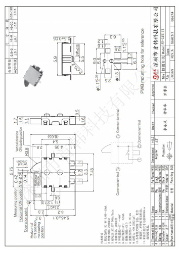
深圳市首韩科技有限公司限位开关深圳市首韩科技有限公司SHENZHEN SHOUHAN TECHNOLOGYCO.,LTDTel:*************Fax:*************客户Customer:产品名称Project:规格型号Part No:贵公司承认印Approal slgnatures料号/Part No.签章/Signatures日期Date:拟制/Drawn 李春风审核/Check 钟华华批准/Approved罗孝金1深圳市首韩科技有限SH-31R 11T1. 一般特性General Characteristics正常温度: 5℃~35℃ 相对湿度: 45%~85% 1.1 额定值(Rating Value): DC 5V 10mA1.2 工作温度(Work Temperature Range): -10℃ ~ 60℃1.3 存贮温度(Store Temperature Range): -20℃ ~ 80℃1.4 正常测试条件(未有特殊说明量测在以下条件进行):General test condition (Tests and measurements shall be made under the following standard conditions unless otherwise specified):RH 气 压: 8,600~10,600帕Temperature: 5℃~35℃ Relative humidity: 45%~85% Air pressure: 8,600~10,600 pa2. 产品外观及尺寸要求 Appearance & Dimension Requirement2.1 产品外形结构紧凑,无配合不良.The structure of product is compact, and assembly of parts has no badness.2.2 产品塑胶部件无严重缩水、披锋、欠注、斑点、破损或变形现象.The plastic parts of product have no serious defects such as very serious shrink, scarcity,fleck, disrepair, transmutation, etc.2.3 产品引脚和外壳无严重氧化、脏污、变形、毛刺或电镀不良.Lead feet and shell have no serious defects such as oxidation, smudge, disrepair, burr, defects on plating.2.4 开关操作顺畅,节奏感强,无明显卡塞现象。
上海龙整电器接近开关说明书

上海龙整电器接近开关说明书
上海龙整电器接近开关已开发为在IO链路环境中工作,在这种环境下,需要监测和记录传感性能。
由于上海龙整电器接近开关的简单和全面定制,客户可以从许多设置组合中进行选择,并满足他们的特定要求。
随着这些具有ToF技术和集成IO-Link功能的光电上海龙整电器接近开关的推出,Carlo Gavazzi通过更广泛的产品供应来加强其在市场上的地位。
具有IO链路功能的LD30激光光电上海龙整电器接近开关:IP69K不锈钢外壳或IP67塑料外壳两个独立的开关信号通道(SSC)远程背景抑制可通过电位计或IO连接在50至1000mm之间调节感应距离操作方式:单点、两点、窗口
温度报警和记录功能
逻辑门功能:AND,OR,X-OR和选通复位触发器
工作温度:-25°C至+50°C(-13°至+122°F)
延时功能:开启延迟、关闭延迟、单次前缘或后缘,值在1ms到32767分钟之间两个完全可配置的独立输出:NPN/PNP、推拉、外部输入或远程示教NO或NC 2米PVC电缆或M8插头
IO链路通信v1.1这些上海龙整电器接近开关设计用于满足工业要求,并能准确检测食品和饮料、机床、包装和包装、塑料和橡胶以及材料处理
市场中不同尺寸、形状或表面结构的物体。
DMC-PD1097 电磁开关说明书

The motion sensor switch assembly is available in any one
of fourns. The switch body is
designed to be installed onto the idler end spindle hex broach
DORNER MFG. CORP.
580 Industrial Drive, PO Box 20 Hartland, WI 53029-0020 USA
USA TEL 1-800-397-8664 (USA) FAX 1-800-369-2440 (USA)
Outside the USA: TEL 1-414-367-7600, FAX 1-414-367-5827
of a 2100 or 4100 series Dorner Conveyor (Figure 2). Each assembly is shipped with the 3″ (70 mm) and wider conveyor spring (Item 3 of Figure 1) installed onto the switch body shaft. The 2″ (44 mm) wide conveyor spring (Item 4 of Figure 1) is furnished with a tag that directs “Do NOT Discard”. As necessary, remove and replace the 3″ spring with the 2″ spring, before installing switch body into idler end spindle. Proceed with the installation as follows:
交流电流感应开关中文说明书

LANTAI
AC CURRENT SWITCH
DC CURRENT SWITCH
LAN TAI 电流感应开关
USER’S MANUAL 中文使用说明书
产品执行标准:GB13850-2009
Rev:1.0
广州市国蓝电子科技有限公司
GZ GOLDLAN Technology Development C.,Ltd
1 / 3广州市国蓝电子科技有限公司
2 / 3
广州市国蓝电子科技有限公司
LT 电流感应开关
LT Series AC Current Switch
产品概述
> 电流感应开关具有安全可靠、反应速度快、体积小、安装及使用方便,是自动化设备、电力监控
的理想伴侣。
> 与传统的互感器、热保护器等相比,电流感应开关具有更准确、更及时的监测与控制。
> 电流感应开关广泛应用于变电站、变频调速、逆变装置、电解电镀、路灯监控、煤矿、矿山电机
等行业领域。
产品特性
> 互感式电流监测,输入输出安全隔离,自供电(自供电仅交流型,直流型需外接DC 电源供电); > 被监测电流可达200A ;
> 磁滞< 1% ,可在强磁环境下使用;
> 无触点电子开关,反应速度快,无通断次数限制; > 监测阀值1~200A 可任意设定;
> 外壳采用防火材料ABS ,黑色或蓝色
产品性能参数
产品型号说明
产品型号列表
安装和使用前请详细阅读 使用说明书及注意用电安全
3 / 3
广州市国蓝电子科技有限公司
标签说明 产品外
形与尺寸
产品的安装与常用接线、应用
PLC
典型应。
电流感应开关中文使用说明书
+
-
+
-
③ 整定电流调节
通过可调电位器调节整定电流值;
穿芯电流
AC (≤200A )
当 I穿芯 > I整定 时,开关导通 I穿芯 < I整定 时,开关断开
③ SPS 135系列 交/直流电源 接线图
注:SPS135系列 接 交流电源时不论正负极。
④
④ 产品参数
详细产品参数见表“性能参数 ” 与“产品选型表”。
应用示例
输出信号 输入信号
交流电源
负 载
PLC
电源 U V W
电流
电流感应开关 发生动作 过载应 开关信号
电机停止
时间
穿芯电流
AC (≤200A )
电机 启动器
SPS 240系列 交流电源 接线图
注:SPS240系列只接交流电源。
电流感应开关与PLC配合控制电机
产品选型表
产品型号
SPS135-FIX-RD-NO SPS135-FIX-CP-NO SPS135-ADJ-RD-NO SPS135-ADJ-RD-NC SPS135-ADJ-CP-NO SPS135-ADJ-CP-NC SPS240-ADJ-RD-NO SPS240-ADJ-RD-NC SPS240-ADJ-CP-NO SPS240-ADJ-CP-NC
杭州双星普天科技开发有限公司 地址:杭州市下沙经济技术开发区8号大街和达创意设计园5幢6层 电话:86-571-8668 3443 网址:
2/2
电流整定值
固定0.5A 固定1A 可调整 可调整 可调整 可调整 可调整 可调整 可调整 可调整
状态指示灯
红色 红色 绿色/红色 绿色/红色 绿色/红色 绿色/红色 绿色/红色 绿色/红色 绿色/红色 绿色/红色
欧姆尼克 1000 系列电磁感应器说明书

Dimensions: [mm]749252070749252070BC749252070749252070T e m p e r a t u r eT pT L749252070Cautions and Warnings:The following conditions apply to all goods within the product series of WE-CST of Würth Elektronik eiSos GmbH & Co. KG:General:•This electronic component is designed and manufactured for use in general electronic equipment.•Würth Elektronik must be asked for written approval (following the PPAP procedure) before incorporating the components into any equipment in fields such as military, aerospace, aviation, nuclear control, submarine, transportation (automotive control, train control, ship control), transportation signal, disaster prevention, medical, public information network etc. where higher safety and reliability are especially required and/or if there is the possibility of direct damage or human injury.•Electronic components that will be used in safety-critical or high-reliability applications, should be pre-evaluated by the customer. •The component is designed and manufactured to be used within the datasheet specified values. If the usage and operation conditions specified in the datasheet are not met, the wire insulation may be damaged or dissolved.•Do not drop or impact the components, as the component may be damaged.•Würth Elektronik products are qualified according to international standards, which are listed in each product reliability report. Würth Elektronik does not warrant any customer qualified product characteristics beyond Würth Elektroniks’ specifications, for its validity and sustainability over time.•The responsibility for the applicability of the customer specific products and use in a particular customer design is always within the authority of the customer. All technical specifications for standard products also apply to customer specific products.Product specific:Soldering:•The solder profile must comply with the technical product specifications. All other profiles will void the warranty.•All other soldering methods are at the customers’ own risk.•Strong forces which may affect the coplanarity of the components’ electrical connection with the PCB (i.e. pins), can damage the component, resulting in avoid of the warranty.Cleaning and Washing:•Washing agents used during the production to clean the customer application might damage or change the characteristics of the wire insulation, marking or plating. Washing agents may have a negative effect on the long-term functionality of the product.•Using a brush during the cleaning process may break the wire due to its small diameter. Therefore, we do not recommend using a brush during the PCB cleaning process.Potting:•If the product is potted in the customer application, the potting material might shrink or expand during and after hardening. Shrinking could lead to an incomplete seal, allowing contaminants into the core. Expansion could damage the component. We recommend a manual inspection after potting to avoid these effects.Storage Conditions:• A storage of Würth Elektronik products for longer than 12 months is not recommended. Within other effects, the terminals may suffer degradation, resulting in bad solderability. Therefore, all products shall be used within the period of 12 months based on the day of shipment.•Do not expose the components to direct sunlight.•The storage conditions in the original packaging are defined according to DIN EN 61760-2.•The storage conditions stated in the original packaging apply to the storage time and not to the transportation time of the components. Packaging:•The packaging specifications apply only to purchase orders comprising whole packaging units. If the ordered quantity exceeds or is lower than the specified packaging unit, packaging in accordance with the packaging specifications cannot be ensured. Handling:•Violation of the technical product specifications such as exceeding the nominal rated current will void the warranty.•Applying currents with audio-frequency signals may result in audible noise due to the magnetostrictive material properties.•Due to heavy weight of the components, strong forces and high accelerations may have the effect to damage the electrical connection or to harm the circuit board and will void the warranty.•The temperature rise of the component must be taken into consideration. The operating temperature is comprised of ambient temperature and temperature rise of the component.The operating temperature of the component shall not exceed the maximum temperature specified.These cautions and warnings comply with the state of the scientific and technical knowledge and are believed to be accurate and reliable.However, no responsibility is assumed for inaccuracies or incompleteness.Würth Elektronik eiSos GmbH & Co. KGEMC & Inductive SolutionsMax-Eyth-Str. 174638 WaldenburgGermanyCHECKED REVISION DATE (YYYY-MM-DD)GENERAL TOLERANCE PROJECTIONMETHODCHC001.0032022-10-20DIN ISO 2768-1mDESCRIPTIONWE-CST Current SenseTransformer ORDER CODE749252070SIZE/TYPE BUSINESS UNIT STATUS PAGEImportant NotesThe following conditions apply to all goods within the product range of Würth Elektronik eiSos GmbH & Co. KG:1. General Customer ResponsibilitySome goods within the product range of Würth Elektronik eiSos GmbH & Co. KG contain statements regarding general suitability for certain application areas. These statements about suitability are based on our knowledge and experience of typical requirements concerning the areas, serve as general guidance and cannot be estimated as binding statements about the suitability for a customer application. The responsibility for the applicability and use in a particular customer design is always solely within the authority of the customer. Due to this fact it is up to the customer to evaluate, where appropriate to investigate and decide whether the device with the specific product characteristics described in the product specification is valid and suitable for the respective customer application or not.2. Customer Responsibility related to Specific, in particular Safety-Relevant ApplicationsIt has to be clearly pointed out that the possibility of a malfunction of electronic components or failure before the end of the usual lifetime cannot be completely eliminated in the current state of the art, even if the products are operated within the range of the specifications.In certain customer applications requiring a very high level of safety and especially in customer applications in which the malfunction or failure of an electronic component could endanger human life or health it must be ensured by most advanced technological aid of suitable design of the customer application that no injury or damage is caused to third parties in the event of malfunction or failure of an electronic component. Therefore, customer is cautioned to verify that data sheets are current before placing orders. The current data sheets can be downloaded at .3. Best Care and AttentionAny product-specific notes, cautions and warnings must be strictly observed. Any disregard will result in the loss of warranty.4. Customer Support for Product SpecificationsSome products within the product range may contain substances which are subject to restrictions in certain jurisdictions in order to serve specific technical requirements. Necessary information is available on request. In this case the field sales engineer or the internal sales person in charge should be contacted who will be happy to support in this matter.5. Product R&DDue to constant product improvement product specifications may change from time to time. As a standard reporting procedure of the Product Change Notification (PCN) according to the JEDEC-Standard inform about minor and major changes. In case of further queries regarding the PCN, the field sales engineer or the internal sales person in charge should be contacted. The basic responsibility of the customer as per Section 1 and 2 remains unaffected.6. Product Life CycleDue to technical progress and economical evaluation we also reserve the right to discontinue production and delivery of products. As a standard reporting procedure of the Product Termination Notification (PTN) according to the JEDEC-Standard we will inform at an early stage about inevitable product discontinuance. According to this we cannot guarantee that all products within our product range will always be available. Therefore it needs to be verified with the field sales engineer or the internal sales person in charge about the current product availability expectancy before or when the product for application design-in disposal is considered. The approach named above does not apply in the case of individual agreements deviating from the foregoing for customer-specific products.7. Property RightsAll the rights for contractual products produced by Würth Elektronik eiSos GmbH & Co. KG on the basis of ideas, development contracts as well as models or templates that are subject to copyright, patent or commercial protection supplied to the customer will remain with Würth Elektronik eiSos GmbH & Co. KG. Würth Elektronik eiSos GmbH & Co. KG does not warrant or represent that any license, either expressed or implied, is granted under any patent right, copyright, mask work right, or other intellectual property right relating to any combination, application, or process in which Würth Elektronik eiSos GmbH & Co. KG components or services are used.8. General Terms and ConditionsUnless otherwise agreed in individual contracts, all orders are subject to the current version of the “General Terms and Conditions of Würth Elektronik eiSos Group”, last version available at .Würth Elektronik eiSos GmbH & Co. KGEMC & Inductive SolutionsMax-Eyth-Str. 174638 WaldenburgGermanyCHECKED REVISION DATE (YYYY-MM-DD)GENERAL TOLERANCE PROJECTIONMETHODCHC001.0032022-10-20DIN ISO 2768-1mDESCRIPTIONWE-CST Current SenseTransformer ORDER CODE749252070SIZE/TYPE BUSINESS UNIT STATUS PAGE。
中文说明书 EC200-K
5.14 输送........................................................................................................................ 26
5.15 微量泵放流 (填充后,清洁) ............................................................................... 27
5.9.5 介质密度................................................................................................................ 17
5.9.6 初始压力监控公差值............................................................................................ 19
5.2
连接 ..........................................................................................................................
5.5
开机 .........................................................................................................................11
5.12 选择输送系统 dosing program......................................................................... 25
BD SENSORS GmbH DS 200电子压力开关说明书

BD SENSORS GmbH BD-Sensors-Straße 1 Tel.: +49 (0) 92 35 / 98 11- 0 www.bdsensors.de D - 95199 ThiersteinFax: +49 (0) 92 35 / 98 11- 11*****************DS 200Electronic Pressure SwitchStainless Steel Sensoraccuracy according to IEC 60770: standard: 0.35 % FSO option: 0.25 % FSONominal pressurefrom 0 ... 100 mbar up to 0 ... 600 bar Contacts1, 2 or 4 independent PNP contacts, freely configurable Analogue output2-wire: 4 ... 20 mA3-wire: 4 … 20 mA / 0 … 10 V others on request Special characteristics►indication of measured values on a 4-digit LED display ►rotatable and configurable display moduleOptional versions►IS-versionEx ia = intrinsically safe for gases ►pressure sensor welded ►customer specific versionsThe electronic pressure switch DS 200 is the successful combination of► intelligent pressure switch ►digital displayand has been specially designed for numerous applications in various industrial sectors.As standard the DS 200 offers a PNP contact and a rotatable display module with 4-digit LED display. Optional versions like e.g. an intrinsically safe version, max. four contacts and an analogue output complete the profile. Preferred areas of use arePlant and machine engineering Heating and air conditioningEnvironmental engineering (water – sewage – recycling)pressure and levelExplosion protection (only for 4 … 20 mA / 2-wire)Approval AX14-DS 200 IBExU 06 ATEX 1050 Xzone 1: II 2G Ex ia IIC T4 Gb (connector) / II 2G Ex ia IIB T4 Gb (cable) Safety technical maximumvaluesU i = 28 V, I i = 93 mA, P i = 660 mW, C ≈ 0 nF, L i≈ 0 µHMax. switching current 670 mAPermissible temperatures forenvironment-25 ... 70 °CConnecting cables (by factory) cable capacitance: signal line/shield also signal line/signal line: 100 pF/m cable inductance: signal line/shield also signal line/signal line: 1 µH/m6 the real switching current in the application depends on the power supply unitMiscellaneousDisplay 4-digit, red 7-segment-LED displaydigit height 7 mmrange of indication -1999 ... +9999accuracy 0.1 % ± 1 digitdigital damping 0.3 … 30 sec (programmable);measured value update 0.0 … 10 sec (programmable)Current consumption (without contacts) 2-wire signal output current:max. 25 mA3-wire signal output current:approx. 45 mA + signal current 3-wire signal output voltage:approx. 45 mAIngress protection IP 65Installation position any 7Weight min. 160 g (depending on mechanical connection)Operational life 100 million load cyclesCE-conformity EMC Directive: 2014/30/EU Pressure Equipment Directive: 2014/68/EU (module A) 8 ATEX Directive 2014/34/EU7 Pressure switches are calibrated in a vertical position with the pressure connection down. If this position is changed on installation there can beslight deviation in the zero point for pressure ranges p N≤ 1 bar.8 This directive is only valid for devices with maximum permissible overpressure > 200 barWiring diagrams2-wire-system (current)3-wire-system (current/voltage)Pin configurationElectrical connection M12x1plastic(5-pin) M12x1metal(5-pin)M12x1plastic(8-pin)ISO 4400 Binderseries 723(5-pin)cable colours(IEC 60757)Supply +Supply –Signal + (only 3-wire)Contact 1Contact 2Contact 3Contact 4 13245--13245--13245671233---13245--WH (white)BN (brown)GN (green)GY (grey)PK (pink)--Shieldviapressure portplug housing/pressure portviapressure portgroundcontactplug housing/pressure portGNYE(green-yellow)2 134 5325 81746452 13 453 24 1pIV Ssupply +supply –contact 1contact 2R LR LAsupply +signal +contact 1V SA/VpI/Usupply –contact 2contact 3contact 4R LR LR LR Lwww.bdsensors.deElectrical connections (dimensions mm / in)M12x1 plastic M12x1 metal M12x1 plastic (5-pin) (5-pin) (8-pin)ISO 4400Binder series 723cable outlet 9(5-pin)9 different cable types and lengths available; permissible temperature depends on kind of cable;standard: 2 m PVC cable (without ventilation tube, permissible temperature: -5 ... 70 °C)Dimensions (mm / in)rotatability of display module ** for nominal pressure p N > 400 bar increases the length of device by 19 mm (without explosion protection) or by 39 mm (with explosion protection) pressure and levelMechanical connection (dimensions mm / in)G1/2" DIN 3852G1/2" EN 8371/2" NPTG1/4" DIN 3852 G1/4" EN 837 1/4" NPTG3/4" flush DIN 3852 G1/2" flush DIN 3852(0.1 bar ≤ p N≤ 40 bar)(0.1 bar ≤ p N≤ 40 bar)length of device: 87.5 mm (without plug) length of device: 103 mm (without plug)metric threads and other versions on requestDS200_E_010223www.bdsensors.de Tel.: +49 (0) 92 35 / 98 11- 0www.bdsensors.deFax: +49 (0) 92 35 / 98 11- 11*****************©223BD|SENSORSGmbH–Thespecificationsgiveninthisdocumentrepresentthestateofengineeringatthetimeofpublishing.Wereservetherighttomakemodificationstothespecificationsandmaterials.--------78078H 78121.00.1010001.60.1616002.50.2525004.00.4040006.00.60600010 1.0100116 1.6160125 2.5250140 4.0400160 6.0600110010100216016160225025250240040400260060600210010031601603250250340040036006003-1 … 0X 1029999consult0137J E 9consult124consultstandard for p N > 0.4 bar:0.35 % FSO 3standard for p N ≤ 0.4 bar:0.50 % FSO 5option for p N ≥ 0.4 bar:0.25 % FSO 29consult100204T A 0999consult100200300400flush sensorflush sensor N 00N 40999consultFKM129consult000999consult1 from 60 bar: measurement starts with ambient pressure2 absolute pressure possible from 0.4 bar3 with IS version max. 1 contact is possible4 with connector ISO 4400 and output 2-wire version only max. 1 contact possible; with 3-wire version no contact possible5 4 contacts and M12x1, 8-pin only possible in combination and together with 4 ... 20 mA/3-wire; 0 ... 10 V/3-wire on request6 standard: 2 m PVC cable without ventilation tube (permissible temperature: -5 ... 70 °C); others on request 7not possible for nominal pressure p N > 40 bar; for G3/4“ flush nominal pressure abs. on request8 welded version only with pressure ports according to EN 837 and NPT ; possible for nominal pressure ranges p N≤ 40 bar01.02.2023metal versionN 11plastic versionN 01M 50standard customercustomerwithout (welded version)customer1/2" NPT 1/4" NPT 7F 00G3/4" DIN 3852 withK 00G1/4" DIN 3852G1/4" EN 837G1/2" DIN 3852 withcustomerG1/2" DIN 3852G1/2" EN 8374 contactsmale plug M12x1 (5-pin) /plastic versioncustomercustomer1 contact2 contacts 4 … 20 mA / 2-wire 0 … 10 V / 3-wire4 … 20 mA / 3-wire, adjustable intrinsic safety 4 … 20 mA / 2-wiregauge in mH 2O absolute in bar customer© 2023 B D |S E N S O R S G m b H - T h e s p e c i f i c a t i o n s g i v e n i n t h i s d o c u m e n t r e p r e s e n t t h e s t a t e o f e n g i n e e r i n g a t t h e t i m e o f p u b l i s h i n g . W e r e s e r v e t h e r i g h t t o m a k e m o d i f i c a t i o n s t o t h e s p e c i f i c a t i o n s a n d m a t e r i a l s .DS 200gauge in bar 7male plug M12x1 (8-pin) /male plug M12x1 (5-pin) /8113, 43, 435male plug Binder series 723 (5-pin)546cable outlet with PVC cable2222male and female plug ISO 4400without。
K-TEK AT200 智能阀门位置传感器说明书

FEATURES∙ High Accuracy .01 % of Full Scale with PatentedMagnetostrictive Sensing Technology∙ No Direct Connection Between Valve Stem and Transmitter∙ Microprocessor Based∙ Simple Calibration: Pushbutton or HART Protocol ∙ Never Requires Recalibration∙ Dual Compartment Housing with Separate Field Terminal Compartment ∙ Field Replaceable Module ∙ Built-in RFI/EMI FilterDESCRIPTIONThe AT200 Valve Positioner is a compact, high accuracy valve position transmitter that uses K-TEK’spatented Magnetostrictive sensing technology. In the valve positioning application, the transmitter is bolted to the yoke of the actuator with two (2) mounting brackets that are supplied with the transmitter. A third bracket is secured to the stem con-nector. This bracket holds the magnet that provides the signal to the transmitter. The clearance between the magnet and the sensing tube of the AT200 is approximately 1/4” (6.35mm). This dimension is not critical and can vary slightly along the length of the transmitter. The magnet should not contact the sensing tube at any point in its travel. The brackets supplied with the transmitter do not include mounting holes. These will be drilled in the field to accommodate the various sizes of actuators that will be encountered. The transmitter is calibrated in place by using either the integral pushbuttons or LCD. The vertical alignment of the transmitter is not critical and the zero and span can be set anywhere along the active portion of the transmitter. There is an unusable range of 2” (50.8 mm) at the transmitter and 3.5” (88.9 mm)on the bottom end of the sensing tube.SPECIFICATIONSElectronic TransmitterHousing Type Explosion Proof Powder Coated Cast Aluminum, Dual Compartment Standard Optional 316L Stainless Steel, Dual Compartment Electrical Connection 1/2” FNPTMounting Includes magnet with valve stem bracket and two (2) activator yoke mounting brackets Measuring Range 0.5 - 30 ft. (0.15 - 9.1 m)Repeatability 0.005% of full scale or 0.015”, whichever is greater Non-Linearity 0.01% of full scale or 0.35”, whichever is greater Accuracy 0.01% of full scale or 0.050”, whichever is greater Loop Supply Voltage 13.5 to 36 VDCPolarity Protection Diode in series with loopOutput Standard 4-20 mAdc; Manual field calibration via pushbuttons;Optional: HART protocol, Honeywell DE, Foundation Fieldbus ITK4.01 Compliant Dampening Field Adjustable by means of pushbuttons. Range: 0.1 to 36 seconds Burnout Jumper selectable upscale (21 mAdc) or downscale (3.6 mAdc) Temperature -40 to 170°F (-40 to 77°C) ambient Humidity 0 to 100% R.H., non-condensingSensor Tube Material 316L Stainless Steel standardApprovals FM Factory Mutual Research Corp and CSA Canadian Standards Association Hazardous XP/ I /1/ ABCD / T6; DIP / II, III / 1 / EFG / T6IS / I / 1 / CD / T4—ELE0001 / A [excludes RI (secondary analog output) & Honeywell DE option] NI / I / 2 / ABCD / T4 Type 4X ATEX:Flameproof: II 1/2 GD EEx d IIC T6 T80°C; 02 ATEX 132659 Intrinsically Safe: II 1/2 GD EEx ia IIB T6; 02 ATEX 132658 [excludes RI secondary analog output) & Honeywell DE option]Ingress protection classification: IP67OPTIONS∙ Local Indication with scrolling LCD Display∙ HART Protocol Output ∙ Honeywell DE Output∙ Foundation Fieldbus Output ∙ Glass Viewing Window ∙ 316L SS Enclosure∙21-Segment Strapping TableAT200 Valve PositionerORDERING INFORMATION AT200/a/b/c/d/e/f/g/h: /a Mounting B Bottom Connected Electronic Housing BW Bottom Connected Electronic Housing with Window cover T Top Connected Electronic Housing TW Top Connected Electronic Housing with Window Cover /b Transmitter Configuration L Standard Local Transmitter Process Temperature up to 200°F (93°C) /c Transmitter Housing A Standard Dual Compartment Aluminum Housing S Dual Compartment Stainless Steel Housing /d Probe Type R1 5/8” OD Probe Standard /e Electronic Module with One Analog Output X None M4A One Level, LCD Indicator. HART Protocol or Honeywell DE Protocol Default is HART Add “D” suffix to module option for Honeywell DE (class 0 support) Add “F” suffix to module option for Foundation Fieldbus ITK 4.01 compliant Add “S” suffix to module option for 21 segment strapping table (not available with “D” suffix) /f Second Analog Output (Hart protocol only) X None RI Second Electronic Module with One Analog Output and LCD Indicator Notes: 1. Available only with HART Protocol module M4A 2. Housing type will be the same as primary transmitter housing (/c above) /g Approvals FM Factory Mutual and CSA Canadian Standard Association CEX ATEX Flameproof, NEPSI CEI ATEX I.S., NEPSI /h Measuring Length ML Specify the measuring length in inches or mmAvailable Accessories:VP: Valve Positioning Transmitter (This ordering code is required to order AT200 with positioning capabilities)MGT: Magnet Assembly (includes magnet with valve stem bracket and two (2) actuator yoke mounting brackets) Note: This accesory is required . Please specify the following: Valve Type/Size, Actuator Type/Size, and Valve Stem length and O.D. dimensions.VI-Transmitter: Vibration Isolator (One Isolator includes: one (1) rubber grommet one (1) split ring collar and one (1) mounting bracket)M20 ISO Fitting: M20 Female Electrical Connection05390036 ActuatorMagnet AssemblyExample Installation: AT200 Valve Positioner and Hydraulic Control ValveMagnetMounting BracketsPrairieville, Louisiana 70769 USA Telephone: +(1) 225-673-6100 AT200VP-0202-1 Rev e (08-2010)For latest version of this data sheet, visitEmail:******************Website: 。
LK2000使用说明书
使用说明书
V1.0
武汉朗开电气有限公司 2014年4月
目录
1. 概述...........................................................................................................................................1 1.1. 关于本说明书 ...............................................................................................................1 1.2. 产品清单 .......................................................................................................................1
4. 接线说明.................................................................................................................................14 4.1. 接线要求 .....................................................................................................................14 4.2. 典型接线图 .................................................................................................................14
电流感应开关选型与使用说明书 2017年-1版

产品概述电流感应开关是为了安全、简捷、方便监控或检测用电设备电流,利用电流的电磁互感原理,采用了先进的无源自供电技术研制而成的开关量输出检测、监控、保护报警型产品。
A200K系列有单调单组或单调双组同步型;A210K系列是上下限型,有单调或双调;A220K 系列是双调双组异步型、D200K系列是直流开关产品(此系列需要辅助电源12Vdc‐24Vdc)产品综合应用了无源自供电(或称:干节点技术)、电子式无触点开关、LED红绿灯电流状态显示以及一体化设计,使得应用安装简捷方便;应用多圈精密调节器旋扭,使产品性能更加稳定;采用自动换档技术,使检测电流从1‐200A之间连续可调。
采用电磁互感技术,不仅使产品的功耗极其微小、解决了大电流时接触点的发热问题,还使得输入电流与输出信号的隔离高度安全,耐压绝缘值超过5000Vac@1min@2mA,可安全应用于700V以下所有用电设备中 。
电流感应开关(又称为电流检测开关),一般是当穿心电流高于或低于设定的越限值时,便输出一个信号或关断这个信号。
本文介绍了3款类型共27个型号的电流检测开关、电流感应开关产品。
将同一类型及作用的合在一起介绍,可以起到快速熟悉及选型的效果。
产品一般技术特性适用频率: 50~400Hz ,A2xxK交流系列;D200K系列是直流电流启动时间: 0.2秒内, 延时产品加上设定的延时时间;产品尺寸: 70×50×26mm,(安装尺寸70×80×26mm);安装孔中心距离: 66mm;安装孔直径: 4mm;穿心孔直径: 19.5mm;穿心电流范围: 1‐200A,(以实际产品型号为准);开关额定负载能力:0.5A@240Vac 或 0.5A@300Vdc,最大值可达1.0A工作温度: ‐10℃~55℃工作湿度: 0~95% ,无冷凝IP等级: IP30产品型号列表及功能简述:二十多款型号,总有一款适合你!!序号 产品型号 功能说明 备注1 A200K‐OA 交流常开2 A200K‐OL 交流常开+延时3 A200K‐CA 交流常闭4 A200K‐CL 交流常闭+延时5 A200K‐OF 交流常开‐固定不可调6 A200K‐DM 断电后延时(1‐15分) 同功能,仅延时时间不同,需要延时1‐30分的请说明。
电气安全检测仪器ESA601入门手册
ADA02触摸开关,电容式触摸开关,感应开关_规格书V4.2

规格说明书2通道电容式触摸感应IC 两路自锁式开关(ON/OFF)输出ADA02 V4.2全国客服中心电话:4006-992-661 直线电话:0755-8369-3048 8297-7857 8297-7641 自动传真:0755-2263-4057 E-mail: sinoada@ 企业 QQ: 800-000-251 官方网站: 资料在公司官方网站上会随时更新,敬请留意!目 录 1. 概述 ......................................................................................................................................... 3 2. 特性简介 .................................................................................................................................. 3 3. 功能描述 .................................................................................................................................. 3 4. 封装(SOP8/DIP8 封装) ............................................................................................................ 4 5. 管脚描述 .................................................................................................................................. 5 6 电气特性 ................................................................................................................................... 6 7. 应用电路 .................................................................................................................................. 6 8. 应用说明 .................................................................................................................................. 7 9. 修改记录 .................................................................................................................................. 8 第 2 页 共 8 页1. 概述ADA02 是一款2通道电容式触摸感应IC, 内置强大的电容感应触摸算法,广泛适用于各种控制面板应用,可 直接兼容原机械式轻触按键(带锁开关)的处理信号。
Pointek ULS200 超音波非接触式开关用户手册说明书
4■OverviewThe Pointek ULS200 is an ultrasonic non-contacting switch withtwo switch points for level detection of bulk solids, liquids andslurries in a wide variety of industries; ideal for sticky materials.■Benefits•2 switch outputs for high-high, high, low, and low-low levelalarms or pump up/pump down control•Integral temperature compensation•AC or DC power supply•Electronics provided with fail-safe function•Threaded and sanitary fitting clamp process connections•Polycarbonate enclosure, Type 6/NEMA 6/IP67•Easy, two-button programming ■ApplicationThe measuring range for bulk solids is max. 3 m (9.8 ft) and 5 m(16.4 ft) for liquids and slurries. Unlike invasive contacting de-vices, there is no material buildup on the sensor.The level switch has a rugged design, combining the transducer and electronics in one durable device. It has no moving parts and is virtually maintenance-free.The transducer, available in ETFE or PVDF copolymer, is inert to most chemicals. This means the device can be used in thechemical, petrochemical, water, and wastewater industries. A sanitary version of the ULS200, with an industry standard flange option, is easy to remove from the application for cleaning. It thus satisfies the prerequisites for use in the food, beverage, and pharmaceutical industries. The Pointek ULS200 delivers supe-rior performance while reducing maintenance, downtime, and equipment replacement costs.•Key Applications: liquids, slurries, fluid materials, pluggedchute detection, chemical industry■DesignInstallationThe Pointek ULS200 should be mounted in an area that is within the temperature range specified and that is suitable to the enclo-sure rating and materials of construction. The cover should be accessible to allow programming, wiring and display viewing.It is advisable to keep the Pointek ULS200 away from high volt-age or current runs, contactors and SCR control drives.Locate the Pointek ULS200 so that it has a clear sound path per-pendicular to the material surface. The sound path should not in-tersect the fill path, rough walls, seams, rungs etc.Mounting and InterconnectionThe Pointek ULS200 is available in three thread types: 2" NPT, R 2" (BSPT), EN 10226 or PF2 and can be fitted with the optional75 mm (3 inch) flange adapter for mating to 3" ASME, DN 65, PN10, and JIS 10K 3B sized flanges.Separate cables and conduit may be required to conform tostandard instrumentation wiring or electrical codes.4/1214■ConfigurationPointek ULS200 mounting■Technical specificationsMode of operation Measuring principle Ultrasonic level switchMeasuring range Measuring range in liquids 0.25... 5 m (0.8... 16.4 ft)Measuring range in bulk solids 0.25... 3 m (0.8... 9.8 ft)OutputAC Version (relay)2 SPDT Form C contacts, rated 5 A at 250 V AC or 30 V DC, resistive load; rated 1 A at 48 V DC resistive loadDC Version (relay)2 SPDT Form C contacts, rated 5 A at 30 V DC, resistive load; rated 1 A at 48 V DC resistive loadDC Version (transistor) 2 switches, rated max. 100 mA, 48 V DC Accuracy AC/DC version •Resolution 3 mm (0.1inch)•Repeatability0.25% of measuring range Rated operation conditions Installation conditions •Location Indoors/outdoors •Beam angle12°Ambient conditions •Ambient temperature-40... +60 °C (-40... +140 °F)•If mounted in metal threads -20... +60 °C (-5... +140 °F)Medium conditions •Process pressure 0.5 bar (7.25 psi) max.Design Material Polycarbonate with gasket WeightApprox. 1.5 kg (3.3 lb)Transducer material PVDF or ETFE copolymerThreaded mounting 2" NPT [(Taper), ANSI/ASME B1.20.1]R 2" [(BSPT), EN 10226]or G 2" [(BSPP), EN ISO 228-1]•Optional flange adapterFor 3" ASME, DN 65, PN 10, and JIS 10 K3BSanitary mounting 4" sanitary fitting clampPower supply AC version100... 230 V AC, ± 15%, 50/60 Hz, max. 12 VA, 5 W DC version18... 30 V DC, 3 WDisplays and controls DisplayLCD, three digits, 9 mm (0.35inch) high, for display of distance between sensor face and material, multi-segment graphic for operating state Memory EEPROM, non-volatile Programming2 keysElectronics/enclosureConnection: terminal block, max. 2.5 mm 2 (14 AWG) solid/1.5 mm 2 (16AWG) strandedDegree of protection IP67/Type 6/NEMA 6Cable inlet2 x ½" NPT or 2 x PG 13.5Certificates and approvalsCE, CSA US/C , FM4■OptionsPointek ULS200 optional flange adapter, dimensions in mm (inch)Available with Enclosure/cable inlet option 2 only2)Available with Approvals option K onlySelection and Ordering data Order codeFurther designsPlease add "-Z" to Article No. and specify Ordercode(s)Stainless steel tag [69 x 50 mm (2.71 x 1.97inch)]:Measuring-point number/identification(max. 27 characters) specify in plain textY15Operating InstructionsAll literature is available to download for free, in arange of languages, at /processinstrumentation/documentationAccessories Article No.Tag, stainless steel, 12 x 45 mm (0.47 x 1.77inch),one text line, suitable for enclosures7ML1930-1ACUniversal Box Bracket Mounting Kit7ML1830-1BK3" ASME, DN 65 PN 10, JIS 10K 3B ETFE Flangeadapter for 2" NPT7ML1830-1BT3" ASME, DN 65 PN 10, JIS 10K 3B ETFE Flangeadapter for 2" BSPT7ML1830-1BU2" BSPT Locknut, plastic7ML1830-1DQ2" NPT Locknut7ML1830-1DT4" sanitary mounting clamp7ML1830-1BRSpare PartsPolycarbonate Lid7ML1830-1LG4/1224/1234■Dimensional drawingsPointek ULS200, dimensions in mm (inch)■Circuit diagramsPointek ULS200 connections。
电流感应开关 A210K-OR

电流感应开关A210K-OR、又称:电流保护器、过电流保护器,电流感应过载报警器,过电流感应开关复位开关,是一款开关量输出的常开式的可调复位值的电流感应式过流保护、报警产品,是广州市国蓝电子科技有限公司根据电流的电磁原理研制而成,该产品采用先进的无源自供电技术,高度隔离的互感式技术,应用时不用接辅助电源,仅有开关线输出,性能稳定,精度高,应用及安装均非常方便简,是过电流保护、报警的不可多得的好帮手。
A210K-OR的姊妹篇产品:A200K-OR ;她们的区别是:A210K-OR是常开复合型,没穿心电流时端子开关是断开的,有穿心后开关闭合,过电流启动后开关再次断开;A200K-OR是常开型,没穿心电流或穿心电流没达到启动值时,端子开关是断开的,过电流启动后,开关闭合。
她们的过电流启动方向相反,一个断开,一个闭合。
本过电流感应开关A210K-OR采用了高度隔离的电磁感应原理,所以又称为电流互感式报警器,本 A210K-OR 保护器是开关量输出,在1.0Aac~200Aac 的范围内,本产品 A210K-OR 可根据实际的需要自定义设定过流保护、报警点,也可以设定复位值,开关量输出。
本产品A210K-OR不仅采用无触点的电子式开关量输出,无开关次数限制,启动时无火花,反应迅速,而且体积小,免维护,寿命长。
更由于采用了互感应技术,功耗为毫瓦级,是一款目前世界上唯一一款能够真正替代热继电器的电子式过流保护、报警产品。
输出端子接口采用高压电子管,应用电子技术,输出端口可以直接连接交流接触器,交流或直流继电器,耐压高达240Vac,峰值达500Vp-p;过电流大,最大可达4A@5秒时。
额定为0.5A。
端口负载规格 :0.5A@240Vac/dc 。
此规格可以满足国内外绝大部分应用要求(超过250V、1.0A除外)。
动作时间在200mS(毫秒)以内。
本产品 A210K-OR 可以连续 7天 X 24 小时不间断工作,高度不超过海拔3000米为宜(所有含有电子元器件的产品均有高度要求)。
感应式电流保护器C系列产品说明说明书

| C SERIES (CA, CM, CDA, CDM)2 TO 40 AMP COMMERCIAL THERMAL CIRCUIT BREAKERSPECIFICATIONSThe C series thermal breakers are designed to protect wiring and meet the harshest environmental requirements. The C series closed construction circuit breakers are weatherproof sealed for protection against moisture, dust, grease, fuel vapors and other harsh environments. The C series breakers are compact, lightweight and designed to interrupt short circuits or overloads, and combine trip-free protection with fast response time. Typical applications are protection of wire cable of accessory circuits, equipment and battery protection in construction and off-road equipment, marine, recreational vehicles (RV’s), mining, agricultural equipment and electric (hybrid) vehicles.FeaturesIntroduction• 30VDC or 120VAC, 2 to 40 Amps • Open and closed construction• Automatic and manual reset options • Ignition protected SAE J1171• Weatherproof SAE J553• UL Recognized E36869ORDERING OPTIONSDERATING CURVE: Leave blank for none I: Optional mounting nutsPerformance characteristics are based on room temperature (77°F, 25°C). Consult derating curve for ambient temperatures significantly higher or lower than standard room temperature.Example: At 77°F (25°C) the device is calibrated to hold at 100% of rated current (1) and trip at 135% of rated current (2). At 140°F (60°C), the same device will hold at approximately 78% of rated current (3), and trip at approximately 115% of rated current (4).Sensata Technologies, Inc. (“Sensata”) data sheets are solely intended to assist designers (“Buyers”) who are developing systems that incorporate Sensata products (also referred to herein as “components”). Buyer understands and agrees that Buyer remains responsible for using its independent analysis, evaluation and judgment in designing Buyer’s systems and products. Sensata data sheets have been created using standard laboratory conditions and engineering practices. Sensata has not conducted any testing other than that specifically described in the published documentation for a particular data sheet. Sensata may make corrections, enhancements, improvements and other changes to its data sheets or components without notice.Buyers are authorized to use Sensata data sheets with the Sensata component(s) identified in each particular data sheet. HOWEVER, NO OTHER LICENSE, EXPRESS OR IMPLIED, BY ESTOPPEL OR OTHERWISE TO ANY OTHER SENSATA INTELLECTUAL PROPERTY RIGHT, ANDNO LICENSE TO ANY THIRD PARTY TECHNOLOGY OR INTELLECTUAL PROPERTY RIGHT, IS GRANTED HEREIN. SENSATA DATA SHEETS ARE PROVIDED “AS IS”. SENSATA MAKES NO WARRANTIES OR REPRESENTATIONS WITH REGARD TO THE DATA SHEETS OR USE OF THE DATA SHEETS, EXPRESS, IMPLIED OR STATUTORY, INCLUDING ACCURACY OR COMPLETENESS. SENSATA DISCLAIMS ANY WARRANTY OF TITLE AND ANY IMPLIED WARRANTIES OF MERCHANTABILITY, FITNESS FOR A PARTICULAR PURPOSE, QUIET ENJOYMENT, QUIET POSSESSION, AND NON-INFRINGEMENT OF ANY THIRD PARTY INTELLECTUAL PROPERTY RIGHTS WITH REGARD TO SENSATA DATA SHEETS OR USE THEREOF.All products are sold subject to Sensata’s terms and conditions of sale supplied at SENSATA ASSUMES NO LIABILITY FOR APPLICATIONS ASSISTANCE OR THE DESIGN OF BUYERS’ PRODUCTS. BUYER AmericasFlame Enterprises Contact Name:Bob Correa, Director of Product Management Direct Phone: +1 (240) 236-9802E-mail:***************************************|WebTel: 1-800-854-2255 or 1-818-700-2905Fax: 1-818-407-5080Peerless Electronics Contact Name:Steve Gunther, National Sales Manager Direct Phone: +1 (516) 594-3509E-mail:***************************************************************|Web Tel: 1-800-285-2121Fax: 1-800-222-8096Europe, Middle East & Africa Flame Enterprises Contact Name:Bob Correa, Director of Product Management Direct Phone: +1 (240) 236-9802E-mail:***************************************|WebTel: 1-800-854-2255 or 1-818-700-2905Fax: 1-818-407-5080CONTACT USAUTHORIZED DISTRIBUTORSAUTHORIZED SALES REPRESENTATIVESCountry Representative Contact E-mailPhoneBrazil Sonnensys Technologies Maury Sampaio ***************************+55 12 99768 1100Austria Telemeter Robert Jall ******************49 906 70693-26Belgium JB Controls Jean Jacques Boher *********************33 (0)1 46 91 93 30Czech Republic TelemeterRobert Jall ******************49 906 70693-26Denmark Sensor Control Nordic Peter BJÖRKDAHL **********************46 (0)8 122 006 92Estonia Sensor Control Nordic Peter BJÖRKDAHL **********************46 (0)8 122 006 92Finland Sensor Control Nordic Peter BJÖRKDAHL **********************46 (0)8 122 006 92France JB Controls Jean Jacques Boher *********************33 (0)1 46 91 93 30Germany Telemeter Robert Jall ******************49 906 70693-26Greece PanSystem Stefano Vitone ****************************39 335 7169958Israel Admati Dori Shifman ***************972 (0)50 331 4700Italy PanSystemStefano Vitone ****************************39 335 7169958Latvia Sensor Control Nordic Peter BJÖRKDAHL **********************46 (0)8 122 006 92Lithuania Sensor Control Nordic Peter BJÖRKDAHL **********************46 (0)8 122 006 92Luxembourg JB Controls Jean Jacques Boher*********************33 (0)1 46 91 93 30Netherlands TBDNorway Sensor Control Nordic Peter BJÖRKDAHL **********************46 (0)8 122 006 92Poland Radiotechnika Tomasz Półtoraczyk ******************************.pl 48 7132 70 765Portugal PanSystem Stefano Vitone ****************************39 335 7169958Slovakia Telemeter Robert Jall ******************49 906 70693-26Spain PanSystemStefano Vitone ****************************39 335 7169958Sweden Sensor Control Nordic Peter BJÖRKDAHL **********************46 (0)8 122 006 92Switzerland JB Controls Jean Jacques Boher *********************33 (0)1 46 91 93 30Turkey Eltronik Ergn Kosem ******************90 312 440 7815UK Charcroft Julie Protheroe *****************************01591 612240Australia AeroDefense Trent Ralph *********************.au +61 7 5503 0552China Pomic Ltd.James Cai **********************+1 (360) 915-7806China (ACCBs only)Shanghai Jin Feng Electronics & Inst CoWang Min-Gang *******************.com +86-21-62712648India Hical Technologies VB Venkatesh **********************+91 98450-12341Indonesia Precision Technologies Aaron Lim ********************.sg +65 (62) 73 45 73 x125Japan Intertek Industries Masa Ikeda ****************************+1 (310) 309-9661Korea Aero Sensors Corp.Jonathan Jo **********************.kr +82 2 557 5355Malaysia Precision Technologies Aaron Lim ********************.sg +65 (62) 73 45 73 x125New Zealand AeroDefense Trent Ralph *********************.au +61 7 5503 0552Singapore Precision Technologies Aaron Lim ********************.sg +65 (62) 73 45 73 x125TaiwanSensata TechnologiesBob Jacques********************+1 (805) 716-0586。
- 1、下载文档前请自行甄别文档内容的完整性,平台不提供额外的编辑、内容补充、找答案等附加服务。
- 2、"仅部分预览"的文档,不可在线预览部分如存在完整性等问题,可反馈申请退款(可完整预览的文档不适用该条件!)。
- 3、如文档侵犯您的权益,请联系客服反馈,我们会尽快为您处理(人工客服工作时间:9:00-18:30)。
产品概述
电流感应开关是为了安全、简捷、方便监控或检测用电设备电流,利用电流的电磁互感原理,采用了先进的无源自供电技术研制而成的开关量输出检测、监控、保护报警型产品。
A200K系列、A210K系列、A220K系列、D200K系列(此系列需要辅助电源12Vdc-24Vdc)产品综合应用了无源自供电(或称:干节点技术)、电子式无触点开关、LED红绿灯电流状态显示以及一体化设计,使得应用安装简捷方便;应用多圈精密调节器旋扭,使产品性能更加稳定;采用自动换档技术,使检测电流从1-200A之间连续可调。
采用电磁互感技术,不仅使产品的功耗极其微小、解决了大电流时接触点的发热问题,还使得输入电流与输出信号的隔离高度安全,耐压值超过5000Vac@1min@2mA,可安全应用于1000V以下所有用电设备中。
电流感应开关(又称为电流检测开关),一般是当穿心电流高于或低于设定的越限值时,便输出一个信号或关断这个信号。
本文介绍了3款类型共22个型号的电流检测开关、电流感应开关产品。
将同一类型及作用的合在一起介绍,可以起到快速熟悉及选型的效果。
产品一般技术特性
适用频率:50~400Hz ,A2xxK交流系列;D200K系列是直流电流
启动时间:0.2秒内,延时产品加上设定的延时时间;
产品尺寸:70×50×26mm,(安装尺寸70×80×26mm);
安装孔中心距离:66mm;
安装孔直径:4mm;
穿心孔直径:19.5mm;
穿心电流范围:1-200A,(以实际产品型号为准);
开关额定负载能力:0.5A@240Vac或0.5A@300Vdc
工作温度:-10℃~55℃
工作湿度:0~95% ,无冷凝
IP等级:IP30
通用型产品尺寸:
交流及直流通用外壳及尺寸
温馨提示:本文档所提及的电流感应检测开关的开关端子K1、K2的耐压(Vp-p)值是不高于500V,超过此电压值将会永久损坏开关产品。
所以,如果产品的端子K1、K2应用于345V、380V或450V等高压时,请特别说明,此需预定制。
各种型号的应用与调试:
三、调复位值型A200K-OR、A210K-OR:
实际上,A200K-OR、A210K-OR是一款特殊型的A200K-OA、A200K-CA型产品,不同的是-OR型是在-OA/-CA型的基础上增加复位值可调的功能。
一般时,常开或常闭的复位值固定在10%左右,而-OR 型则是将复位值由固定的变为可调的而已,由10%~50% 。
从下图的Return%可知。
从上图的说明中就可以知道,此类感应开关产品的典型应用就是:一台电机自动控制另一台电机。
图上已有相关文字说明。
此两款检测开关的调试:先调节CS(Current)锁定电流启动值(绿灯亮开关断开,红灯亮开关闭合),再调复位值,复位值的调试也和调延时的一样,先调至最小处再调至要求的复位处。
当然还有很多其它的应用,例如打桩机的应用,由于工地上的电压不稳定,当380V市电在370V~400V之间变化时,工作中的电机的电流也会发生相应的变化;比如一台16.5KW@380V的电机在400V时重载的电流(单相电流)在25A左右,而在380V时重载的电流则在23A左右,是不一样的;同样地,不同电压值的轻载电流值也不一样。
为了能顺利地读取重载时的电流值,则要对检测开关的复位值提出要求,由此可见,-OR类型产品更适合于电压不稳的场合。
九、电流感应检测开关在超大电流时的应用:
——超大电流的解决方案
如下图所示,右边是用电设备,中间是电流互感器,左边为供电设备。
经常的情况下会遇到我们要检测监测的电流值超过电流感应开关的最大额定值,为此需要引入中间过渡转换设备。
为了能对大电流、超大电流(如电流为2500A~3000A时)进行安全的监控检测,中间加入一个电流互感器(变比为3000:5),再如下图所示的接法,就可以实现对超大电流进行实时监控检测了。
使用注意事项:
一、本文所有提到的开关产品均不能应用于阳光的直射之下,及工作时温度高于55℃的环境之中,以及潮湿、滴水之处,本文所提及的开关并不防水――IP等级为:IP30。
二、文中所有提及的开关的开关端子的电流承载额定值为:0.5A@240Vac/dc;禁止未通过负载而直接上电,否则会永久性损坏产品。
三、应用产品时的穿心电流值请用于标签上的电流范围之内,如果电流值低于或超过标签上规定的范围,请使用以下办法处理:1、低于产品所允许的最小电流值,例如最小电流值为1.0A,而实际的应用电流为0.3A,可采用多绕圈数来实现,0.3A*4TS=1.2A 的计数方法;2、如果应用的电流值超过产品所允许的最大电流值,则需要加接一个互感器来实现应用,例如实际电流大小为2500A,则可加接一个3000:5的电流互感器,如果上图中的:电流检测开关在超大电流时的应用。
四、本文所述的开关产品的穿心均是只能通过一条电流线,使用中是禁止两条或以上的电流线穿过的,否则开关是不能起到正常监测作用的。
在安装与使用过程中,如遇到疑惑或问题,请先联系你的销售人员进行情况说明。
本司的技术服务员会进行跟进服务,请勿自行拆修,否则将会失去应有的服务。
1、在开关端子上接上电源前必须接上负载,如接触器、继电器、灯泡等。
2、穿心孔只能穿过一根电源线,不能穿过2根,否则就会因电流的一正一反而抵消,感应开
关不起监控检测的作用。
3、本文所有A200K、A210K、D200K系列的开关产品的穿心电流均在1~200A之间,应用时电流值须在此范围内。
4、本文所述之感应开关产品的开关负载能力的额定值均为0.5A@240Vac/dc,有部分的可能为0.3ARTD 额定值。
最大值默认为额定值的2倍。
