E914IT中文资料
IT9120系列功率表IT9121E用户指南说明书

功率表IT9120系列用户指南型号:IT9121E版本号:V1.4声明© Itech Electronic, Co., Ltd. 2019根据国际版权法,未经Itech Electronic, Co., Ltd. 事先允许和书面同意,不得以任何形式(包括电子存储和检索或翻译为其他国家或地区语言)复制本手册中的任何内容。
手册部件号IT9121E-402288版本第1版,2019 年12月12日发布Itech Electronic, Co., Ltd.商标声明Pentium是Intel Corporation在美国的注册商标。
Microsoft、Visual Studio、Windows 和MS Windows是Microsoft Corporation 在美国和/或其他国家/地区的商标。
担保本文档中包含的材料“按现状”提供,在将来版本中如有更改,恕不另行通知。
此外,在适用法律允许的最大范围内,ITECH 不承诺与本手册及其包含的任何信息相关的任何明示或暗含的保证,包括但不限于对适销和适用于某种特定用途的暗含保证。
ITECH对提供、使用或应用本文档及其包含的任何信息所引起的错误或偶发或间接损失概不负责。
如ITECH与用户之间存在其他书面协议含有与本文档材料中所包含条款冲突的保证条款,以其他书面协议中的条款为准。
技术许可本文档中描述的硬件和/或软件仅在得到许可的情况下提供并且只能根据许可进行使用或复制。
限制性权限声明美国政府限制性权限。
授权美国政府使用的软件和技术数据权限仅包括那些定制提供给最终用户的权限。
ITECH 在软件和技术数据中提供本定制商业许可时遵循FAR 12.211(技术数据)和12.212(计算机软件)以及用于国防的DFARS252.227-7015(技术数据-商业制品)和DFARS 227.7202-3(商业计算机软件或计算机软件文档中的权限)。
安全声明小心标志表示有危险。
W91414A中文资料
Publication Release Date: January 1995
-5-
Revision A3
W91410 SERIES
Flash OFF HOOK , F
1. Flash key can be stored as a digit in memory. 2. The system will return to the initial state after the break time is finished. 3. The flash function timing diagram is shown in Figure 5.
input from a µC can also be used. A valid key entry is defined as a single row being connected to a single column.
I, O A built-in inverter provides oscillation with an inexpensive 3.579545 MHz crystal or ceramic resonator.
W91410 SERIES
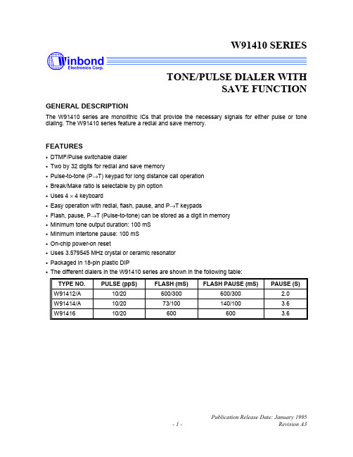
TONE/PULSE DIALER WITH SAVE FUNCTION
GENERAL DESCRIPTION
The W91410 series are monolithic ICs that provide the necessary signals for either pulse or tone dialing. The W91410 series feature a redial and save memory.
ES1J中文资料(Won-Top Electronics)中文数据手册「EasyDatasheet - 矽搜」

A C
B D
F HG E
SMA/DO-214AC
Dim
Min
A
2.50
B
4.00
C
1.20
D
0.152
E
4.80
F
2.00
G
0.051
H
0.76
在毫米所有尺寸
Max 2.90 4.60 1.60 0.305 5.28 2.44 0.203 1.52
最大额定值和电气特性
@TA = 25°C除非另有说明
100
1.0 1.2 1.4
Tj = 25 °C f = 1.0MHz
20 10
10 C,电j 容(pF)
,峰FS值M 正向浪涌电流(A)
I0
1
1
10
100
1
10
100
循环次数在60Hz
VR,反向电压(V)
图. 3峰值正向浪涌电流
图. 4典型结电容
50Ω NI(非感性)
10Ω NI
trr +0.5A
0
0 25 50 75 100 125 150 175
T L ,焊接温度 图. 1正向电流降额曲线
( ° C)
30
Pulse width 8.3 ms single half-sine-wave
(JEDEC method)
,正F 向电流(A) I 0.01
0 0.2 0.4 0.6 0.8
VF,正向电压(V) 图. 2典型正向特性
出货数量
7500 /磁带和卷轴 7500 /磁带和卷轴 7500 /磁带和卷轴 7500 /磁带和卷轴 7500 /磁带和卷轴 7500 /磁带和卷轴 7500 /磁带和卷轴
E105MF1AKE中文资料(itt)中文数据手册「EasyDatasheet - 矽搜」

2-1,5-4
2-1,5-4
2-1,5-4
DPDT
Part number shown: E201SD1CBE MOM. = Momentary
Terminal Numbers For Reference Only
** Wiring for 3-way switch, see Section O.
触点材料
B Gold K 金,锡 - 铅 P 黄金,雾锡 Q 镀银 M 银,锡 - 铅 S 银,雾锡 G 镀金银 L 镀金银,锡,铅 R 镀金银,雾锡
Seal E Epoxy
芯片中文手册,看全文,戳
开关功能
NO. POLES
MODEL NO.
E101 E103 SP E105 E107 E108
DPDT
G
切换
Dimensions are shown: Inch (mm) Specifications and dimensions subject to change
芯片中文手册,看全文,戳
C&K E系列
密封微型拨动开关
端子 A RIGHT ANGLE, PC THRU-HOLE
执行器
M .300"高 S 0.500"高 L3 塑料,0.940"高
衬套
D1 .250"高 F1 导电,
.250"高* D9 .280"高 Y 螺纹,0.350"高
G * F1可与SP和DP
切换 唯一版本,请参阅
页G-24
端接
A 直角,PC通孔 AV2 垂直直角,PC通孔 C PC直通孔 V3 0.460"高,V型支架 Z 焊片 A3 直角,PC通孔 AV3 垂直直角,PC通孔 V6 0.460"高,V型支架 V9 1.150"高,V型支架 V31 0.460"高,管理单元V-支架 V61 0.460"高,管理单元V-支架 W .750"长,绕线 Z3 快速连接
Sennheiser e 914 半导体电容麦克风说明书

FEATURES• Exceptionally lively, clear sound • Three-position sensitivity switch• Three-position bass roll-off/cut-off switch • Very high sound pressure handling capability • Exchangeable capsule• Excellent directivity across the whole frequency range • Wide frequency responseDELIVERY INCLUDES• e 914• pouch• MZQ 800 microphone clamp • MZW 64 windshield • quick guide • safety guideThe e 914 is a high grade condenser microphone for very demanding applications. Its outstanding sound properties qualify the e 914 for highly sophisticated tasks.The e 914 is a perfect microphone for ambitious recordings and live performances. Its main areas of application are acoustic guitars, cymbals, percussion, overhead, orche-stras, grand pianos etc.SPECIFICATIONSTransducer principle pre-polarised condenser microphone Frequency response 20 - 20,000 Hz Pick-up pattern cardioidSensitivity (free field, at 1 k Hz)with pre-attenuation7 mV/Pa2.3 mV/Pa / 0.7 mV/Pa Nominal impedance (at 1 k Hz)100 ΩMin. terminating impedance 1 kΩMax. sound pressure level (at 1 kHz)137/147/157 dB SPL (depen-ding on pre-attenuation)Equivalent noise level A-weighted CCIR-weighted 24 dB(A)34 dBPre-attenuation 0 dB, -10 dB, -20 dB Bassfilterlinearroll-off 130 Hz, 6 dB/oct.cut-off 85 Hz, 18 dB/oct.Phantom powering 48 V / 2.2 mA Connector XLR-3Dimensions ⌀ 24 x 157 mm Weight198 gARCHITECT‘S SPECIFICATIONThe microphone shall be a cardioid prepolarized condenser designed for ambitious recordings and live performances.It shall be fitted with a three-position sensitivity switch (0 d B, −10 dB, −20 dB) and a three-position bass roll-off/cut-off switch (roll-off: 130 Hz with 6 dB/octave, cut-off: 85 H z with 18 dB/octave).The frequency response shall be 20 Hz – 20,000 Hz and the sensitivity (free field, no load) shall be 7 mV/P at 1 kHz. Nominal impedance shall be 100 Ω, with a min. terminating impedance of 1 kΩ. Equivalent noise level shall be 19 dB(A). Maximum SPL at 1 kHz shall be 137 dB with 0 dB preatte-nuation, 147 dB with −10 dB preattenuation or 157 dB with −20 dB preattenuation.The microphone shall operate on 48 V phantom power and shall provide a 3-pin XLR connector. Dimensions shall be 24 x 157 mm (0.94" x 6.18"). Weight shall be 198 grams (6.98 oz).The microphone shall be the Sennheiser e 914.Sennheiser electronic GmbH & Co. KG · Am Labor 1 · 30900 Wedemark · Germany · POLAR PATTERNFREQUENCY RESPONSE30°0°180°150°120°60°90°0510152025dB30°0°180°150°120°60°90°125 Hz 250 Hz 500 Hz 1,000 Hz 2,000 Hz 4,000 Hz8,000 Hz16,000 Hz501002005001,0002,0005,00010,00020,000H z0- 10- 20dB flatroll-off cut-off。
HEDS-9140中文资料
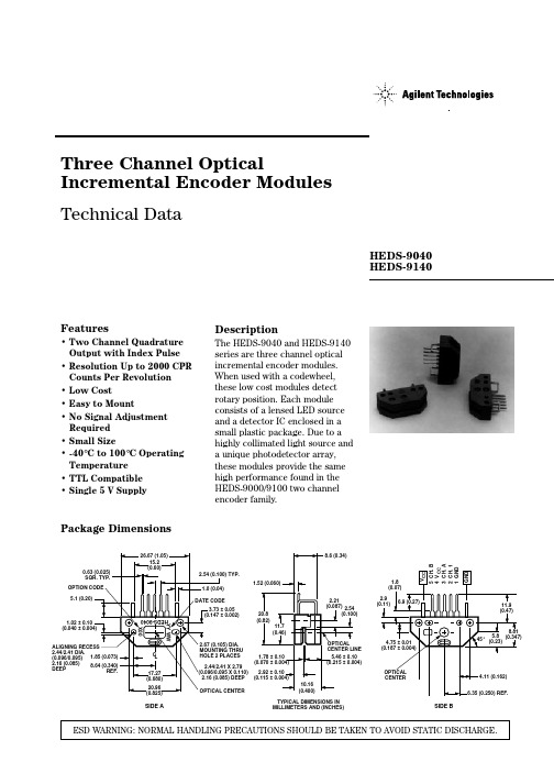
The HEDS-9040 and 9140 provide sophisticated motion control detection at a low cost, making them ideal for high volume applications. Typical applications include printers, plotters, tape drives, and industrial and factory automation equipment.
2.16 (0.085) DEEP
1.78 ± (0.070 ± 0.004)
2.92 ± 0.10 (0.115 ± 0.004)
OPTICAL CENTER
10.16 (0.400)
OPTICAL CENTER LINE
5.46 ± 0.10 (0.215 ± 0.004)
TYPICAL DIMENSIONS IN MILLIMETERS AND (INCHES)
元器件交易网
Three Channel Optical Incremental Encoder Modules
Technical Data
HEDS-9040 HEDS-9140
Features
• Two Channel Quadrature Output with Index Pulse
1.52 (0.060)
DATE CODE
3.73 ± 0.05 (0.147 ± 0.002)
20.8 (0.82)
11.7 (0.46)
2.21 (0.087) 2.54
(0.100)
2.67 (0.105) DIA. MOUNTING THRU HOLE 2 PLACES
MICRO SWITCH 914CE Series 微型精密限位开关数据手册说明书

MICRO SWITCH Miniature Precision Limit Switches914CE SeriesDESCRIPTIONAll MICRO SWITCH 914CE Series compact enclosed switches incorporate fluorocarbon diaphragm sealing to provide reliable protection, meeting NEMA 1, 2, 3, 3R, 4, 6, 6P, and 13, as well as IP66, IP67, and IP68 requirements. Versions with a boot seal also meet NEMA 12 requirements (dust, falling dirt, liquid media with solid contaminates). The cable or connector and basic switch terminals are encapsulated in an epoxy sealant, offering excellent resistance in harsh environments. For low temperature applications (down to -40 °C, -40 °F), CE Series switches can be supplied with low temperature seals and lubricant.The CE Series switches are rugged and versatile switches which can be applied indoors in many harsh factory floor applications, as well as on outdoor equipment in extreme temperatures. A full range of actuators are available,including plain plungers, roller plungers, side rotary, multi-directional wire, and manually operated. The switches are also available with the industry standard, M12 micro-change 4-pin connector. MICRO SWITCH 914CE products meet North American, cURus standards, as well as European CE requirements.VALUE TO CUSTOMERS• Big performance in a small package• Delivers consistent performance in many demanding environments where petroleum, synthetic, or water based fluids are present• Configurable product platform for design versatilityFEATURES• Rugged, compact construction means minimal real estate on equipment• Die-cast zinc housing and fluorocarbon diaphragm maintain a tightly sealed, NEMA 1, 2, 3, 3R, 4, 6, 6P, 12 (boot seal), 13, and IP66/67/68 package• Pre-leaded (UL cable) or supplied with a M12 four-pin connector• Wide selection of actuators, cable length variations, and side and bottom exit cable/connector options• 25 mm hole-hole mounting footprint engineered with a MICRO SWITCH SM switch for consistent, precise actuation • Well suited for up to 10 million actuation cycles (Up to 5 million actuation cycles for wobble actuators)• Gang mounting capability to provide a multi-plunger limit switch• Low temperature variants available for indoor and outdoor applications• cURus, CE approvals for world-wide usePOTENTIAL APPLICATIONS• Machine tools• Off-road equipment • Material handling• Dock locks and dock levelers • Access and mobility solutions • Textile machinery • Robotics• Packaging equipment • Commercial appliances • Print trade machinery • Agricultural machineryDIFFERENTIATION• Diaphragm seal between the actuator and the switch cavity for high performance sealing• CE series uses MICRO SWITCH SM basic switch for consistent, precise actuationPORTFOLIOHoneywell’s MICRO SWITCH 914CE limit switch is part of a comprehensive offering of rugged and reliable limit switches. To view the entire product portfolio, click here .Sensing and Internet of Things002381Issue 7Table 1. SpecificationsTable 2. Electrical Ratings (in amperes)Model example Contacts Rating914CE* - * Silver contacts A914CE* - *G Gold contacts B914CE* -Q, -AQ, -AQ1, -Q2Silver contactsC with 4 pin connector2 SWITCHING AND LEAD IDENTIFICATION914CErow.BOTTOM EXIT OR SIDE EXIT ORIENTATIONThe CE Series has been designed with a pre-wired cable fittedin the bottom of the switch housing. Other variations are availa-ble with a side exit cable.GOLD CONTACT VERSIONSFor low energy applications (up to 30 Vdc, 1 A), gold contactversions of the 914CE switches can be supplied upon request.Sensing and Internet of Things 34 44 mm max.[1.73 in max.]25 mm [0.98 in]16 mm max.[0.63 in max.]40 mm max.[1.57 in max.]Max. free lengthOperating position (OP) 3 mm min. [0.12 in min.]8,0 mm [0.31 in]8,0 mm [0.32 in]7,6 mm [0.30 in]Pretravel (PT)Overtravel (OT)CABLE VERSIONTYPE Q OE Q2TYPE Q1M12thread1/2 x 20 UNF threadTwo (2) holes Ø 5.1 mm [Ø 0.2 in] dia. c/bore10,2 mm dia x 6 mm deep [0.40 in dia x 0.24 in deep](Both sides - option “A” only)GENERAL DIMENSIONS • ALL SWITCHESPRODUCT NOMENCLATURE914CESwitch Type29Actuator TypeOptions 1914CE Series Small Precision Limit Switch–3Cable LengthConnectorsBottom exit is standard.NOTE: not all combinations of model code are available.Please contact your Honeywell provider/representative for assistance.1More than one option may be permissible.PRODUCT SPECIFICATIONS AND LISTINGSContact your Honeywell rep or distributor for additional listingsSensing and Internet of Things 56 Note: part numbers are shown with 3 ft of cable. The -X indicates the number of feet of cable provided. 6-foot, 9-foot, and 12-foot lengths along with custom lengths, are also available.Sensing and Internet of Things 7Note: part numbers are shown with 3 ft of cable. The -X indicates the number of feet of cable provided. 6-foot, 9-foot, and 12-foot lengths along with custom lengths, are also available.8 m WARNINGPERSONAL INJURYDO NOT USE these products as safety or emergency stop devices or in any other application where failure of the product could result in personal injury.Failure to comply with these instructions could result in death or serious injury.m WARNINGMISUSE OF DOCUMENTATION• The information presented in this product sheet is for reference only. Do not use this document as a product installation guide.•Complete installation, operation, and maintenanceinformation is provided in the instructions supplied with each product.Failure to comply with these instructions could result in death or serious injury.ADDITIONAL MATERIALS• Product installation instructions • Product range guide • Product nomenclature tree• Product application-specific information– Limit and enclosed switches application information – Limit and enclosed switches operating characteristics – Limit and enclosed switches reference standards – Limit and enclosed switches typical applications – Product flyer: CE Family Miniature Limit SwitchesWarranty/RemedyHoneywell warrants goods of its manufacture as being free of defective materials and faulty workmanship during the appli-cable warranty period. Honeywell’s standard product warranty applies unless agreed to otherwise by Honeywell in writing; please refer to your order acknowledgment or consult your local sales office for specific warranty details. If warrantedgoods are returned to Honeywell during the period of coverage, Honeywell will repair or replace, at its option, without charge those items that Honeywell, in its sole discretion, finds defec-tive. The foregoing is buyer’s sole remedy and is in lieu of all other warranties, expressed or implied, including those of merchantability and fitness for a particular purpose. In no event shall Honeywell be liable for consequential, special, or indirect damages.While Honeywell may provide application assistance personally, through our literature and the Honeywell web site, it is buyer’s sole responsibility to determine the suitability of the product in the application.Specifications may change without notice. The information we supply is believed to be accurate and reliable as of this writing. However, Honeywell assumes no responsibility for its use.Viton ® is a registered trademark of DuPont Performance Elastomers L.L.C.002381-7-EN | 7 | 06/18© 2018 Honeywell International Inc. All rights reserved.For more informationHoneywell Sensing and Internet of Things services its customers through a worldwide network of sales offices and distributors. For application assistance, current specifications, pricing or the nearest Authorized Distributor, visit or call:Asia Pacific +65 6355-2828Europe +44 (0) 1698 481481USA/Canada+1-800-537-6945Honeywell Sensing and Internet of Things 9680 Old Bailes Road Fort Mill, SC 29707 www. 。
Datasheet MLX90614 中文 数据手册 rev008
10-位 PWM 输出模式是连续输出所测物体温度的标准配置,测量物体的温度范围为-20…120 °C,分辨 率为 0.14 °C。PWM 通过修改 EEPROM 内 2 个单元的值,实际上可以根据需求调整至任何温度范围,而这对 出厂校准结果并无影响。
传感器的测量结果均出厂校准化,数据接口为数字式的 PWM 和 SMBus(System Management Bus) 输出。
作为标准,PWM 为 10 位,且配置为-20˚C 至 120 ˚C 内,分辨率为 0.14 ˚C 的连续输出。
传感器出厂默认,上电复位时为 SMBus 通信。
3901090614 Rev 008
PWM 引脚也可配置为热继电器(输入是 To),这样可以实现简单且性价比高的恒温控制器或温度报警(冰 点/沸点)应用,其中的温度临界值是用户可编程的。在 SMBus 系统里,这个功能可以作为处理器的中断信号, 以此触发读取主线上从动器的值,并确定精度条件。
传感器有两种供电电压选择:5V 或 3V(电池供电)。其中,5V 也可简便的从更高供电电压(例如 8 至 16V)上通过外接元件调制。(具体请参考“应用信息”)
MLX90614 connection to SMBus
图 1: 典型应用电路
2 概述
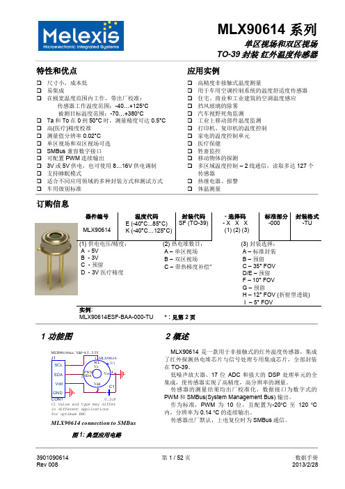
MLX90614 是一款用于非接触式的红外温度传感器,集成 了红外探测热电堆芯片与信号处理专用集成芯片,全部封装 在 TO-39。
低噪声放大器、17 位 ADC 和强大的 DSP 处理单元的全 集成,使传感器实现了高精度,高分辨率的测量。
1N914中文资料
VF, INSTANTANEOUS FORWARD VOLTAGE (V) Fig. 1 Forward Characteristics 1N914, 1N914A
10,000
IR, LEAKAGE CURRENT (nA)
1000
100
10
VR = 20V
1 0 100 200
Tj, JUNCTION TEMPERATURE (°C) Fig. 3 Leakage Current vs Junction Temperature
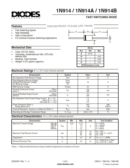
DO-35 Min 25.40 ¾ ¾ ¾ Max ¾ 4.00 0.60 2.00
All Dimensions in mm
Maximum Ratings @ TA = 25°C unless otherwise specified
Characteristic Non-Repetitive Peak Reverse Voltage Peak Repetitive Reverse Voltage Working Peak Reverse Voltage DC Blocking Voltage RMS Reverse Voltage Forward Continuous Current (Note 1) Average Rectified Output Current (Note 1) 1N914 1N914A/B 1N914 1N914A/B Symbol VRM VRRM VRWM VR VR(RMS) IFM IO IFSM Pd RqJA Tj , TSTG Value 100 75 53 150 300 75 200 1.0 1.0 4.0 500 1.68 300 -65 to +175 Unit V V V mA mA A mW mW/°C K/W °C
vishay 1n914 小信号快速开关二极管 数据表.pdf说明书
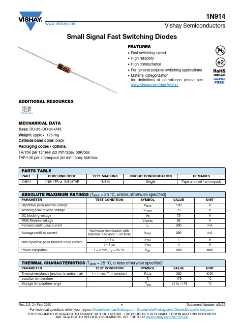
Small Signal Fast Switching DiodesADDITIONAL RESOURCESMECHANICAL DATACase: DO-35 (DO-204AH)Weight: approx. 125 mg Cathode band color: black Packaging codes / options:TR/10K per 13" reel (52 mm tape), 50K/box TAP/10K per ammopack (52 mm tape), 50K/boxFEATURES•Fast switching speed •High reliability •High conductance•For general purpose switching applications •Material categorization:for definitions of compliance please see /doc?999123D 3D3D Model sPARTS TABLEPART ORDERING CODE TYPE MARKINGCIRCUIT CONFIGURATIONREMARKS1N9141N914TR or 1N914TAP1N914SingleTape and reel / ammopackABSOLUTE MAXIMUM RATINGS (T amb = 25 °C, unless otherwise specified)PARAMETERTEST CONDITIONSYMBOL VALUE UNIT Repetitive peak reverse voltage V RRM 100V Working peak reverse voltage V RWM 75V DC blocking voltage V R 75V RMS Reverse voltage V R(RMS)53V Forward continuous current I F 300mA Average rectified currentHalf wave rectification withresistive load and f > 50 MHzI F(AV)200mA Non repetitive peak forward surge current t = 1 s I FSM 1A t = 1 μs I FSM 4A Power dissipationl = 4 mm, T L = 25 °C P tot500mWTHERMAL CHARACTERISTICS (T amb = 25 °C, unless otherwise specified)PARAMETERTEST CONDITION SYMBOL VALUE UNIT Thermal resistance junction to ambient air l = 4 mm, T L = constantR thJA 300K/W Junction temperature T j 175°C Storage temperature rangeT stg-65 to +175°CTYPICAL CHARACTERISTICS (T amb = 25 °C, unless otherwise specified)Fig. 1 - Forward Current vs. Forward Voltage Fig. 2 - Reverse Current vs. Reverse VoltagePACKAGE DIMENSIONS in millimeters (inches): DO-35 (DO-204AH)ELECTRICAL CHARACTERISTICS (T amb = 25 °C, unless otherwise specified)PARAMETER TEST CONDITIONSYMBOLMIN.TYP.MAX.UNIT Forward voltage I F = 10 mA V F 1V Breakdown voltage I R = 100 μA V (BR)100V Peak reverse current V R = 75 V I R 5μA V R = 20 V, T j = 150 °CI R 50μA V R = 20 V I R 25nA Diode capacitance V R = 0, f = 1 MHz C D 4pF Reverse recovery timeI F = 10 mA, i R = 1 mA,V R = 6 V, R L = 100 Ωtrr4nsI R - R e v e r s e C u r r e n t (n A )V R - Reverse Voltage (V)101 100 94 9098Legal Disclaimer Notice VishayDisclaimerALL PRODUCT, PRODUCT SPECIFICATIONS AND DATA ARE SUBJECT TO CHANGE WITHOUT NOTICE TO IMPROV E RELIABILITY, FUNCTION OR DESIGN OR OTHERWISE.V ishay Intertechnology, Inc., its affiliates, agents, and employees, and all persons acting on its or their behalf (collectively,“Vishay”), disclaim any and all liability for any errors, inaccuracies or incompleteness contained in any datasheet or in any other disclosure relating to any product.Vishay makes no warranty, representation or guarantee regarding the suitability of the products for any particular purpose or the continuing production of any product. To the maximum extent permitted by applicable law, Vishay disclaims (i) any and all liability arising out of the application or use of any product, (ii) any and all liability, including without limitation special, consequential or incidental damages, and (iii) any and all implied warranties, including warranties of fitness for particular purpose, non-infringement and merchantability.Statements regarding the suitability of products for certain types of applications are based on Vishay's knowledge of typical requirements that are often placed on Vishay products in generic applications. Such statements are not binding statements about the suitability of products for a particular application. It is the customer's responsibility to validate that a particular product with the properties described in the product specification is suitable for use in a particular application. Parameters provided in datasheets and / or specifications may vary in different applications and performance may vary over time. All operating parameters, including typical parameters, must be validated for each customer application by the customer's technical experts. Product specifications do not expand or otherwise modify Vishay's terms and conditions of purchase, including but not limited to the warranty expressed therein.Hyperlinks included in this datasheet may direct users to third-party websites. These links are provided as a convenience and for informational purposes only. Inclusion of these hyperlinks does not constitute an endorsement or an approval by Vishay of any of the products, services or opinions of the corporation, organization or individual associated with the third-party website. Vishay disclaims any and all liability and bears no responsibility for the accuracy, legality or content of the third-party website or for that of subsequent links.Except as expressly indicated in writing, Vishay products are not designed for use in medical, life-saving, or life-sustaining applications or for any other application in which the failure of the Vishay product could result in personal injury or death. Customers using or selling Vishay products not expressly indicated for use in such applications do so at their own risk. Please contact authorized Vishay personnel to obtain written terms and conditions regarding products designed for such applications. No license, express or implied, by estoppel or otherwise, to any intellectual property rights is granted by this document or by any conduct of Vishay. Product names and markings noted herein may be trademarks of their respective owners.© 2022 VISHAY INTERTECHNOLOGY, INC. ALL RIGHTS RESERVED。
CGD914中文资料
元器件交易网
Philips Semiconductors
Product specification
CATV amplifier module
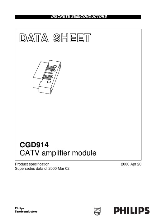
FEATURES • Excellent linearity • Extremely low noise • Excellent return loss properties • Rugged construction • Gold metallization ensures excellent reliability. APPLICATIONS • CATV systems operating in the 40 to 870 MHz frequency range. DESCRIPTION Hybrid amplifier module in a SOT115J package operating with a voltage supply of 24 V (DC), employing both GaAs and Si dies.
2000 Apr 20
2
元器件交易网
Philips Semiconductors
Product specification
CATV amplifier module
CHARACTERISTICS Bandwidth 45 to 870 MHz; VB = 24 V; Tmb = 35 °C; ZS = ZL = 75 Ω. SYMBOL Gp SL FL PARAMETER power gain slope straight line flatness straight line f = 45 MHz f = 870 MHz f = 45 to 870 MHz f = 45 to 100 MHz f = 100 to 800 MHz f = 800 to 870 MHz flatness narrow band s11 input return losses in each 6 MHz segment f = 40 to 80 MHz f = 80 to 160 MHz f = 160 to 320 MHz f = 320 to 550 MHz f = 550 to 650 MHz f = 650 to 750 MHz f = 750 to 870 MHz f = 870 to 914 MHz s22 output return losses f = 40 to 80 MHz f = 80 to 160 MHz f = 160 to 320 MHz f = 320 to 550 MHz f = 550 to 650 MHz f = 650 to 750 MHz f = 750 to 870 MHz f = 870 to 914 MHz s21 s12 CTB phase response reverse isolation composite triple beat f = 50 MHz RFout to RFin 79 chs; fm = 445.25 MHz; note 1 112 chs; fm = 649.25 MHz; note 2 132 chs; fm = 745.25 MHz; note 3 79 chs flat; Vo = 44 dBmV; fm = 547.25 MHz 112 chs flat; Vo = 44 dBmV; fm = 745.25 MHz 132 chs flat; Vo = 44 dBmV; fm = 745.25 MHz Xmod cross modulation 79 chs; fm = 55.25 MHz; note 1 112 chs; fm = 55.25 MHz; note 2 132 chs; fm = 55.25 MHz; note 3 79 chs flat; Vo = 44 dBmV; fm = 55.25 MHz 112 chs flat; Vo = 44 dBmV; fm = 55.25 MHz 132 chs flat; Vo = 44 dBmV; fm = 55.25 MHz CONDITIONS MIN. 19.75 20.2 0.2 −0.25 −0.6 −0.45 − 20 20 18 16 15 14 14 10 21 21 20 19 18 17 16 14 −45 − − − − − − − − − − − − − TYP. 20 21 1 − − − − − − − − − − − − − − − − − − − − − − − − − − − − − − − − − −
IT9121 用户指南

请勿使用已损坏的设备。在使用设备之前,请先检查其外壳。检查是否存在 裂缝或缺少塑胶。请勿在含有易爆气体、蒸汽或粉尘的环境中操作本设备。 功率表的电压和电流测量端子可测试电压最大为 600V、 电流为 20A, 请勿接 入过高的电压和电流,否则会烧坏设备! 请始终使用所提供的电缆连接设备。 在连接设备之前,请观察设备上的所有标记。 在连接 I/O 端子之前,请关闭设备和应用系统的电源。 请勿自行在仪器上安装替代零件,或执行任何未经授权的修改。 请勿在可拆卸的封盖被拆除或松动的情况下使用本设备。 请勿在进行自测试之前连接任何电缆和端子块。 请仅使用制造商提供的电源适配器以避免发生意外伤害。 严禁将本设备使用于生命维持系统或其他任何有安全要求的设备上。
安全声明
手册部件号
IT9121-402145
版本
第2版, 2015 年 2月 27 日 发布 Itech Electronics, Co., Ltd.
小心标志表示有危险。它要求在 执行操作步骤时必须加以注意, 如果不正确地执行或不遵守操作 步骤,则可能导致产品损坏或重 要数据丢失。在没有完全理解指 定的条件且不满足这些条件的情 况下,请勿继续执行小心标志所 指示的任何不当操作。
安全标志
直流电 交流电 既有直流也有交流电 保护性接地端子
ON(电源合) OFF(电源断) 电源合闸状态 电源断开状态
接地端子 危险标志 警告标志(请参阅本手册了解 具体的“警告”或“小心”信息) 地线连接端标识 -
E34-3F3-E160中文资料(ferroxcube)中文数据手册「EasyDatasheet - 矽搜」

芯片中文手册,看全文,戳
飞磁
E型磁芯及配件
E34/14/9 (E375)
GRADE 3F3
3F35
AL (nH) 100 ±5% (1) 160 ±5% (1) 250 ±5% 315 ±5% 400 ±8% 630 ±15% 2125 ±25% 1680 ±25%
Note 1.测结合平等核心跳空一半,锁模力对于A
图3 E34/14/9线圈前:12针.
绕线数据和面产品乘产品 12针 E34/14/9线圈架
单位数
SECTIONS
最低 绕组
AREA (mm 2)
标称 绕组
WIDTH (mm)
1
102
16.5
平均 长研究
TURN (mm)
69.0
0.65 21.9
27.2 max.
2.15 min.
AREA
产品
阂 x仙 (mm 4)
GRADE 3C81
3C90
3C91 3C92 3C94 3C96
AL (nH)
100 ±5% (1) 160 ±5% (1) 250 ±5% 315 ±5% 400 ±8% 630 ±15% 3200 ±25% 100 ±5% (1) 160 ±5% (1) 250 ±5% 315 ±5% 400 ±8% 630 ±15% 2440 ±25% 3200 ±25% 1850 ±25% 2440 ±25% 2125 ±25%
线圈架
对于 E34/14/9线圈前通用数据
参数 线圈架材料 最大工作温度
规范
聚酰胺(PA6.6),玻璃纤维增强,阻燃按照 “UL 94-HB” ; UL文件编号E41938(M) 130 °C, “IEC 60085”, B类
E914中文资料
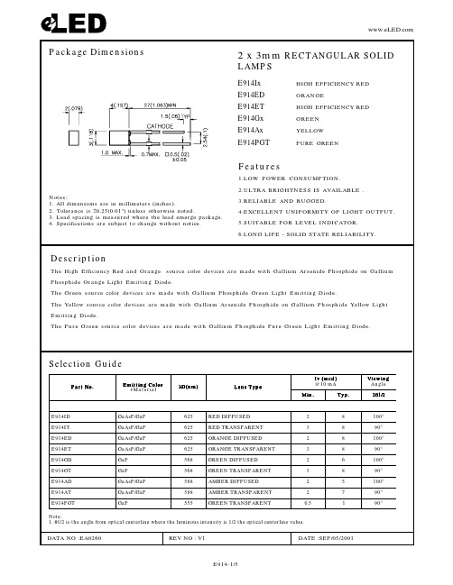
Package Dimensions2 x 3mm RECTANGULAR SOLIDLAMPSFeatures1.LOW POWER CONSUMPTION.2.ULTRA BRIGHTNESS IS AVAILABLE .3.RELIABLE AND RUGGED.4.EXCELLENT UNIFORMITY OF LIGHT OUTPUT.5.SUITABLE FOR LEVEL INDICATOR.6.LONG LIFE - SOLID STATE RELIABILITY.Notes:1. All dimensions are in millimeters (inches).2. Tolerance is ±0.25(0.01") unless otherwise noted.3. Lead spacing is measured where the lead emerge package.4. Specifications are subject to change without notice.E914Ix HIGH EFFICIENCY RED E914ED ORANGEE914ET HIGH EFFICIENCY RED E914Gx GREEN E914Ax YELLOW E914PGTPURE GREENSelection GuideDescriptionThe High Efficiency Red and Orange source color devices are made with Gallium Arsenide Phosphide on Gallium Phosphide Orange Light Emitting Diode.The Green source color devices are made with Gallium Phosphide Green Light Emitting Diode.The Yellow source color devices are made with Gallium Arsenide Phosphide on Gallium Phosphide Yellow Light Emitting Diode.The Pure Green source color devices are made with Gallium Phosphide Pure Green Light Emitting Diode.Note:1. θ1/2 is the angle from optical centerline where the luminous intensity is 1/2 the optical centerline value..o N t r a P r l g i t E o o C n t i m la i r e t a M +λ)m n (D ep y T s n e L )d c m (v I Am 01@g i e i V n w e l g n A n M i .p y T .2θ2/1D I 419E P a G /P s A a G 526D E S U F F I D D E R 28°001T I 419E P a G /P s A a G 526T N E R A P S N A R T D E R 38°09D E 419E P a G /P s A a G 526D E S U F F I D E G N A R O 28°001T E 419E P a G /P s A a G 526T N E R A P S N A R T E G N A R O 38°09D G 419E P a G 865D E S U F F I D N E E R G 26°001T G 419E P a G 865T N E R A P S N A R T N E E R G 38°09D A 419E P a G /P s A a G 885D E S U F F I D R E B M A 25°001T A 419E P a G /P s A a G 885T N E R A P S N A R T R E B M A 27°09TG P 419E Pa G 555TN E R A P S N A R T N E E R G 5.01°09Electrical / Optical Characteristics at T A =25°CAbsolute Maximum Ratings at T A =25°CNotes:1. 1/10 Duty Cycle, 0.1ms Pulse Width.2. 4mm below package base.lo b m y S re t e m a r a P ec i v e D .p y T x a .M U st i n n o i i d n o C t e T t s sλk a e p h t g n e l e v a W k a e P d e R y c n e i c i f f E h g i H e g n a r O n e e r G wo l l e Y ne e r G e r u P 726726565095555m n I F Am 02=λD h t g n e l e v a W e t a n i m o D d e R y c n e i c i f f E h g i H e g n a r O n e e r G wo l l e Y ne e r G e r u P 526526865885555m n I F Am 02=λ∆2/1e n i L l a r t c e p S ht d i w f l a H d e R y c n e i c i f f E h g i H e g n a r O n e e r G wo l l e Y ne e r G e r u P 5454035303m n I F Am 02=C e c n a t i c a p a C d e R y c n e i c i f f E h g i H e g n a r O n e e r G wo l l e Y ne e r G e r u P 5151510254F p V F zH M 1=f ;V 0=V F e g a t l o V d r a w r o F d e R y c n e i c i f f E h g i H e g n a r O n e e r G wo l l e Y n e e r G e r u P 0.20.20.21.252.25.25.25.25.25.2V I F Am 02=I R t n e r r u C e s r e v e R ll A 01A u V R V5=r e t e m a r a P yc n e i c i f f E h g i H de R e g n a r O n e e r G w e Y l l o e e r P ne r G u U s t i n n o i t a p i s s i d r e w o P 501501501501501W m t n e r r u C d r a w r o F C D 0303520352A m ]1[t n e r r u C d r a w r o F k a e P 061061041041531A m eg a t l o V e s r e v e R 55555Ve r u t a r e p m e T e g a r o t S /g n i t a r e p O 04-°58+o T C °C ]2[e r u t a r e p m e T g n i r e d l o S d a e L 062°sd n o ce S 5r o F C。
MM74C914中文资料

October 1987Revised January 1999MM74C914 Hex Schmitt Trigger with Extended Input Voltage © 1999 Fairchild Semiconductor Corporation DS005917.prf MM74C914Hex Schmitt Trigger with Extended Input VoltageGeneral DescriptionThe MM74C914 is a monolithic CMOS Hex Schmitt triggerwith special input protection scheme. This scheme allowsthe input voltage levels to exceed V CC or ground by at least10V (V CC−25V to GND + 25V), and is valuable for applica-tions involving voltage level shifting or mismatched powersupplies.The positive and negative-going threshold voltages, V T+and V T−, show low variation with respect to temperature(typ 0.0005V/°C at V CC= 10V). And the hysteresis, V T+−V T−≥ 0.2 V CC is guaranteed.Featuress Hysteresis: 0.45 V CC (typ.) 0.2 V CC guaranteeds Special input protection:Extended Input VoltageRanges Wide supply voltage range:3V to 15Vs High noise immunity:0.7 V CC (typ.)s Low power TTL compatibility:Fan out of 2 driving 74L Ordering Code:Device also available in Tape and Reel. Specify by appending suffix letter “X” to the ordering code.Connection DiagramsPin Assignments for DIPTop ViewSpecial Input Protection8V ≈ 25Vfor the diodes.Order Number Package Number Package DescriptionMM74C914M M14A14-Lead Small Outline Integrated Circuit (SOIC), JEDEC MS-120, 0.150” NarrowMM74C914N N14A14-Lead Plastic Dual-In-Line Package (PDIP), JEDEC MS-001, 0.300” Wide 2M M 74C 914Absolute Maximum Ratings (Note 1)Note 1: “Absolute Maximum Ratings” are those values beyond which the safety of the device cannot be guaranteed. Except for “Operating Tempera-ture Range”, they are not meant to imply that the devices should be oper-ated at these limits. The Electrical Characteristics tables provide conditions for actual device operation.DC Electrical CharacteristicsMin/Max limits apply across temperature range unless otherwise noted Note 2: Only one input is at ½ V CC , the others are either at V CC or GND.Voltage at any Input Pin V CC − 25V to GND + 25VVoltage at any other Pin−0.3Vto V CC + 0.3VOperating Temperature Range (T A )−40°C to +85°C Storage Temperature Range (T S )−65°C to +150°CPower Dissipation Dual-In-Line 700 mW Small Outline500mWOperating V CC Range 3V to 15VAbsolute Maximum (V CC )18V Lead T emperature (T L )(Soldering, 10 seconds)300°CSymbol Parameter Conditions Min Typ Max UnitsCMOS TO CMOS V T +Positive Going Threshold VoltageV CC = 5V 3.0 3.6 4.3V V CC = 10V 6.0 6.88.6V V CC = 15V9.01012.9V T −Negative Going Threshold VoltageV CC = 5V 0.7 1.4 2.0V V CC = 10V 1.4 3.2 4.0V V CC = 15V2.15 6.0V T + − V T −HysteresisV CC = 5V 1.0 2.2 3.6V V CC = 10V 2.0 3.67.2V V CC = 15V3.0510.8V V OUT(1)Logical“1” Output Voltage V CC = 5V , I O = −10 µA 4.5V V CC = 10V , I O = −10 µA 9.0VV OUT(0)Logical “0” Output Voltage V CC = 5V , I O = +10 µA 0.5V V CC = 10V , I O = +10 µA 1.0V I IN(1)Logical “1” Input Current V CC = 15V , V IN = 25V 0.0055.0µA I IN(0)Logical “0” Input Current V CC = 15V , V IN = −10V −100−0.005µA I CCSupply CurrentV CC = 15V , V IN = − 10V/25V 0.05300µA V CC = 5V , V IN = − 2.5V (Note 2)20µA V CC = 10V , V IN = 5V (Note 2)200µA V CC = 15V , V IN = 7.5V (Note 2)600µA CMOS/LPTTL INTERFACE V IN(1)Logical “1” Input Voltage V CC = 5V 4.3V V IN(0)Logical “0” Input Voltage V CC = 5V0.7V V OUT(1)Logical “1” Output Voltage V CC = 4.75V , I O = −360 µA 2.4V V OUT(0)Logical “0” Output Voltage V CC = 4.75V , I O = 360 µA 0.4V OUTPUT DRIVE (See Family Characteristics Data Sheet) (Short Circuit Current)I SOURCE Output Source Current V CC = 5V , V OUT = 0V , T A = 25°C −1.75−3.3mA (P-Channel)I SOURCE Output Source Current V CC = 10V , V OUT = 0V , T A = 25°C −8.0−15mA (P-Channel)I SINK Output Sink Current V CC = 5V , V OUT = V CC , T A = 25°C 1.75 3.6mA (N-Channel)I SINKOutput Sink Current V CC = 10V , V OUT = V CC , T A = 25°C8.016mA(N-Channel) MM74C914AC Electrical Characteristics (Note 3)T A= 25°C, C L= 50 pF, unless otherwise specifiedNote 3: AC Parameters are guaranteed by DC correlated testing.Note 4: Capacitance is guaranteed by periodic testing.Note 5: C PD determines the no load AC power consumption of any CMOS device. For complete explanation see Family Characteristics Application Note, AN-90.Typical Performance CharacteristicsTypical Transfer CharacteristicsGuaranteed Trip Point RangeTypical ApplicationNote: V CC1= V CC2GND1 = GND2Symbol Parameter Conditions Min Typ Max Units t PHL Propagation Delay from Input to Output V CC= 5V220400ns t PLH V CC= 10V80200ns C IN Input Capacitance Any Input (Note 4)5pF C PD Power Dissipation Capacitance Per Gate (Note 5)20pF 4M M 74C 914Physical Dimensions inches (millimeters) unless otherwise noted14-Lead Small Outline Integrated Circuit (SOIC), JEDEC MS-120, 0.150” NarrowPackage Number M14AF a irch ild d o e s n o t a ssu m e a n y re sp o n sib ility fo r u se o f a n y circu itry d e scrib e d, no circu it p a te n t licen se s a re im p lie d an d F a irch ild re se rv e s th e rig h t a t an y tim e w itho u t n o tice to ch a n g e sa id circu itry a n d sp e cificatio n s.MM74C914 Hex Schmitt Trigger with Extended Input VoltageLIFE SUPPORT POLICYFAIRCHILD’S PRODUCTS ARE NOT AUTHORIZED FOR USE AS CRITICAL COMPONENTS IN LIFE SUPPORT DEVICES OR SYSTEMS WITHOUT THE EXPRESS WRITTEN APPROVAL OF THE PRESIDENT OF FAIRCHILD SEMICONDUCTOR CORPORATION. As used herein:1.Life support devices or systems are devices or systemswhich, (a) are intended for surgical implant into thebody, or (b) support or sustain life, and (c) whose failureto perform when properly used in accordance withinstructions for use provided in the labeling, can be rea-sonably expected to result in a significant injury to the user.2. A critical component in any component of a life support device or system whose failure to perform can be rea-sonably expected to cause the failure of the life support device or system, or to affect its safety or Physical Dimensions inches (millimeters) unless otherwise noted (Continued)14-Lead Plastic Dual-In-Line Package (PDIP), JEDEC MS-001, 0.300” WidePackage Number N14A。
HQxxxx-xxx-3AA中文资料

HQ SeriesSPECIFICATIONS STANDARD*SPECIAL ELECTRICALCenter Frequency (Fc)100 to 1000 Mhz80 to 1400 MHz 3dB Relative Bandwidth (% of FC) 4 to 40 4 to 50 Number of Sections Available 3 to 8 2 to 10 Nominal Impedance50 Ohms50 to 75 Ohms Maximum Insertion Loss See Curve See Curve Maximum VSWR 1.5/1 1.3/1 Attenuation in the Stopband See Graph See GraphMaximum Input Power (Average)(Watts to10,000 ft.)500 x 3dB BW (MHz)(Loss Factor)(Fc MHz)See StandardMaximum Input Power (Peak)(Watts to10,000 ft.)300 x 3dB BW (MHz)Fc (MHz)2,000ENVIRONMENTALShock15 G's25 G's Vibration 5 G's10 G's Humidity90% relative100% relativeINSERTION LOSS:The Maximum Insertion Loss at center frequency is equal to :LF x (N + 0.5) / % 3 dB BW + 0.2 Where:LF= Loss Factor, N= Number of Sections% 3dB BW:3dB BW (MHz) x 100divided byCenter Frequency (MHz) Example:A 3 section HQ with a center frequency of 400 MHz and a 3dB BW of 40 MHz would have,1.5 x 3.5 / 10 = 5.25 / 10 = 0.525 0.525 + 0.2 = 0.8 dBConnectors Available on HQ Series:Lark Code Type C DIM.Inches & MMLarkCodeType C DIM.Inches & MMA SMA JACK.800 & 20.3G N JACK 1.625 & 41.3B SMA PLUG.855 & 22.5H N PLUG 1.585 & 40.3C TNC JACK 1.350 & 34.3L SOLDER MPINAXIAL.625 & 15.9D TNC PLUG 1.280 & 32.5*M SOLDER PINRADIAL.625 & 15.9E BNC JACK 1.350 & 34.3S SPECIALF BNC PLUG 1.280 & 32.5*Not recommended for use with this series.LENGTH:The approximate length of a Lark HQ series filter can be determined by the formula:( 0.5 N + 2 / %BW ) x LC = LWhere N is the number of sections used, % BW is:3dB BW (MHz) x 100divided byCENTER FREQUENCY (MHz)LC is the length constant at the specified center frequency, L is the dimension between theconnectors; C1 and C2 are the connector lengths as shown above. All of the length information given here is approximate. Exact length specifications must be quoted by the factory. If a special length is needed,please submit all of your requirements - both electrical and mechanical. This will enable Lark Engineering to quote the optimum design for your application.Example:A 3 section HQ with a center frequency of 400 MHz a 3dB BW of 40 MHz and SMA jack input and output connectors would be:(1.5 + 0.2) x 1.38 = 2.35 + C1 + C2In most cases, the L dimension is rounded to the nearest 1/4 inch which in this instance would be 2.25inches and the O.A.L. is:2.25 + .800 + .800 =3.85 inches.To convert inches to millimeters multiply x 25.40.Lark Engineering HQ SERIES元器件交易网STOPBAND ATTENUATIONThe graph on the following pages defines the normal specification limits on attenuation Lark bandpass filter series HP, HQ, SF, and SM. The minimum level of attenuation in dB is shown as a "number of 3dB bandwidths from center frequency".Since the frequency characteristics vary for differing bandwidths, it is necessary to establishspecifications for each bandwidth of filter. The different graphs represent various 3dB percentage bandwidths. Intermediate values should be interpolated. The 3dB percentage bandwidth is defined asfollows:STOPATT5.HTM元器件交易网As the 3dB bandwidth is exactly 10% of the center frequency, the answer can be read directly from the 10% graph. Using the 5 section curve at the point -1.5 (255 MHz) we find the minimum level of attenuation is 36dB. At +1.6 (348 MHz) the minimum level of attenuation is 48dB.For special requirements, please contact our Application Engineering Department.STOPBAND ATTENUATIONSTOPBAND ATTENUATIONSTOPATT5.HTM元器件交易网STOPBAND ATTENUATIONSTOPBAND ATTENUATIONSTOPBAND ATTENUATION。
SMMBD914LT3G;中文规格书,Datasheet资料

Notes: 1. A 2.0 kW variable resistor adjusted for a Forward Current (IF) of 10 mA. Notes: 2. Input pulse is adjusted so IR(peak) is equal to 10 mA. Notes: 3. tp » trr
SOT−23 CASE 318 STYLE 8
MAXIMUM RATINGS
Rating Reverse Voltage Forward Current Peak Forward Surge Current
1 ANODE
MARKING DIAGRAM
THERMAL CHARACTERISTICS
Characteristic Total Device Dissipation FR− 5 Board (Note 1) TA = 25C Derate above 25C Thermal Resistance, Junction−to−Ambient Total Device Dissipation Alumina Substrate (Note 2) TA = 25C Derate above 25C Thermal Resistance, Junction−to−Ambient Junction and Storage Temperature Range Symbol PD Max 225 1.8 RqJA PD 556 300 2.4 RqJA TJ, Tstg 417 − 55 to +150 Unit mW mW/C C/W mW mW/C C/W C
3
/
MMBD914LT1G, SMMBD914LT1G, MMBD914LT3G, SMMBD914LT3G
E1UAA20-16.257M中文资料(ECLIPTEK)中文数据手册「EasyDatasheet - 矽搜」
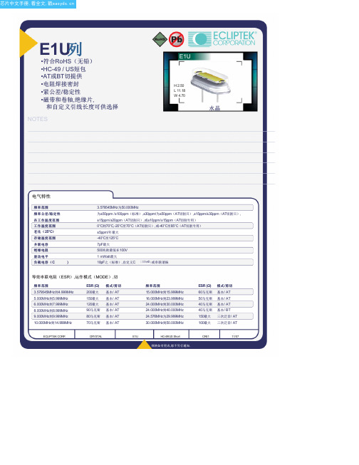
E1U列•符合RoHS(无铅)•HC-49 / US短包•AT或BT切提供•电阻焊接密封•紧公差/稳定性•磁带和卷轴,绝缘片,和自定义引线长度可供选择NOTES H 2.50L 11.18W 4.70水晶_____________________________________________________________________________________________________________________________________________________________________________________________ _____________________________________________________________________________________________________________________________________________________________________________________________ _____________________________________________________________________________________________________________________________________________________________________________________________ _____________________________________________________________________________________________________________________________________________________________________________________________ _____________________________________________________________________________________________________________________________________________________________________________________________ _____________________________________________________________________________________________________________________________________________________________________________________________ _____________________________________________________________________________________________________________________________________________________________________________________________ _____________________________________________________________________________________________________________________________________________________________________________________________ _____________________________________________________________________________________________________________________________________________________________________________________________ _____________________________________________________________________________________________________________________________________________________________________________________________ _____________________________________________________________________________________________________________________________________________________________________________________________ _____________________________________________________________________________________________________________________________________________________________________________________________电气特性频率范围频率公差/稳定性在工作温度范围温度范围工作温度范围老化(25°C)存储温度范围并联电容绝缘电阻驱动电平负载电容(C)3.579545MHz为50.000MHz为±50ppm /±100ppm(标准),±30ppm/为±50ppm(AT切割只),±15ppm/±30ppm(AT切割只),±15ppm/±20ppm(AT切割只),或±10ppm/±15ppm(AT切割专用)0°C到70°C,-20°C至70°C(AT切割只),或-40°C至85°C(AT切割专用)±5ppm/年最大-40°C至125°C7pF最大500兆欧最低在100V1 mWatt最大18pF之(标准),自定义C 10pF,或串联谐振等效串联电阻(ESR),运作模式(MODE),切频率范围3.579545MHz到4.999MHz5.000MHz到5.999MHz6.000MHz到7.999MHz8.000MHz到8.999MHz9.000MHz到9.999MHz10.000MHz到14.999MHz ESR (Ω)200最大150最大120最大90马克斯80马克斯70马克斯模式/剪切基本/ AT基本/ AT基本/ AT基本/ AT基本/ AT基本/ AT频率范围15.000MHz到15.999MHz16.000MHz到23.999MHz24.000MHz到30.000MHz24.000MHz到40.000MHz24.576MHz为29.999MHz30.000MHz到50.000MHzESR (Ω)60马克斯50马克斯40马克斯40马克斯150最大100最大模式/剪切基本/ AT基本/ AT基本/ AT基本/ BT三次泛音/ AT三次泛音/ AT.ECLIPTEK CORP.CRYSTAL E1U HC-49/US Short CR4111/07零件编码指南E1U A A 18 - 20.000M - I2 TR频率公差/稳定性A =±50PPM 25°C时,±0℃至100ppm70℃B =±50PPM,在25°C,±100ppm-20℃至70℃C =±50PPM,在25°C,±100ppm温度范围为-40°C至85°CD =±30ppm25°C时,±0℃50PPM至70℃E =±30ppm25°C时,为±50ppm -20℃至70℃F =±30ppm25°C时,为±50ppm -40°C至85°CG =±15ppm25°C时,±0℃为30ppm至70℃H =±15ppm25°C时,±30ppm-20℃至70℃J =±15ppm25°C时,±30ppm温度范围为-40°C至85°C K =±15ppm25°C时,±0℃为20ppm至70℃L =±15ppm25°C时,±20ppm-20℃至70℃M =±15ppm25°C时,±20ppm温度范围为-40°C至85°C N =±10ppm25°C时,±0℃为15ppm至70℃P =±10ppm25°C时,±15ppm-20℃至70℃包装选择空白=散装,A =盘,TR =卷带式可选项空白=无(标准)CX =自定义引线长度I2 =绝缘子标签频率负载电容S =系列X X = X X pF(自定义)动作模式/水晶切割A =基本/ A TB =三次泛音/ A TD =基本/ BT外形尺寸ALL DIM ENSIONS IN M ILLIM ET ERS 卷带尺寸ALL DIM ENSIONS IN M ILLIM ET ERS环境/机械特性PARAMET ER SPECIFICAT ION 标记规格1000 Pieces per ReelCompliant to EIA-468B精细泄漏测试总泄漏测试铅完整铅端接机械冲击耐焊接热抗溶剂可焊性温度循环振荡M IL-STD-883,方法1014,条件AM IL-STD-883,方法1014,条件CM IL-STD-883 2004方法锡2微米 - 6微米M IL-STD-202,方法213,条件CM IL-STD-202,方法210M IL-STD-202,方法215M IL-STD-883,2002年法M IL-STD-883,法1010M IL-STD-883,方法2007,条件A1号线:电子X X.X X X中号Frequency in MHz(5 Digits Maximum + Decimal).ECLIPTEK CORP.CRYSTAL E1U HC-49/US Short CR4111/07。
PHILIPS HQ914, HQ912 说明书
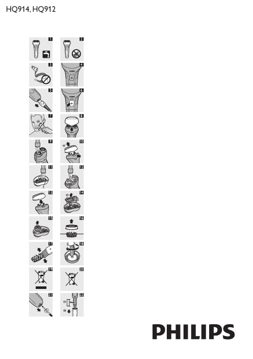
HQ914, HQ912IntroductionCongratulations on your purchase and welcome toPhilips! T o fully benefit from the support that Philips offers, register your product at /welcome .ImportantRead this user manual carefully before you use the appliance and save it for future reference.WarningThis appliance is not intended for use by persons (including children) with reduced physical, sensory or mental capabilities, or lack of experience and knowledge, unless they have been given supervision or instruction concerning use of the appliance by a person responsible for their safety.Children should be supervised to ensure that they do not play with the appliance.Always unplug the shaver before cleaning it under the tap.CautionUse and store the appliance at a temperature between 5°C and 35°C.The shaver complies with the internationally approved IEC safety regulations and can be safely cleaned under the tap (Fig. 1).Be careful with hot water. Always check if the water is not too hot, to avoid burning your hands.This washable shaver is not suitable for shaving in the shower.Do not immerse the shaver in water (Fig. 2).Make sure the adapter does not get wet (your adapter may differ from the one shown in the figure) (Fig. 3).Do not use the shaver in combination with pre-shave lotions, creams, foams, gels or other cosmetic products.Compliance with standardsThis Philips appliance complies with all standards regarding electromagnetic fields (EMF). If handled properly and according to the instructions in this user manual, the appliance is safe to use based on scientific evidence available today.ChargingWhen you charge the shaver for the first time or after a long period of disuse, let it charge continuously for 16 hours. Charging normally takes approx. 8 hours.When the shaver is fully charged, it has a shaving time of up to 30 minutes.For optimal performance, only charge the shaver when the battery is low.Do not leave the appliance connected to the mains for more than 16 hours.Charge indications ChargingWhen the shaver is charging, the charging light lights up green continuously (Fig. 4).Battery lowHQ914: the charging light lights up orange continuously.HQ912: the motor stops or starts running slower.Charging the applianceCharge the appliance when the charging light lights up orange (HQ914) or when the motor stops or starts running slower (HQ912).1 Put the appliance plug in the shaver (Fig. 5).2 Put the adapter in the wall socket.The charging light goes on to indicate that the appliance is charging (Fig. 4).--------------,Note: Charge the shaver for at least 8 hours but not more than 16 hours.3 Remove the adapter from the wall socket andpull the appliance plug out of the shaver when the battery is fully ing the applianceThe shaver cannot be used directly from the mains.1 Remove the protection cap.2 Press the on/off button to switch on theshaver (Fig. 6).3 Move the shaving heads over your skin. Make bothstraight and circular movements (Fig. 7).Note: Shaving on a dry face gives the best results.Note: Your skin may need 2 or 3 weeks to get accustomed to the Philips shaving system.4 When you have finished shaving, press the on/offbutton again to switch off the appliance. 5 Clean the shaver after every use (see chapter ‘Cleaning’).6 Put the protection cap on the shaver to preventdamage to the shaving heads (Fig. 8).Note: Make sure that the lug of the protection cap covers the release button.CleaningNever use scouring pads, abrasive cleaning agents or aggressive liquids such as petrol or acetone to clean the appliance.Be careful with hot water. Always check if the water is not too hot, to avoid burning your hands.Regular cleaning guarantees better shaving performance.The easiest and most hygienic way to clean the appliance is to rinse the shaving unit and the hair chamber with hot water every time you have used the appliance.After every use: shaving unit and hair chamber1 Switch off the shaver, remove the adapter from thewall socket and pull the appliance plug out of the shaver.2 Rinse the outside of the shaving unit under a hottap for some time (Fig. 9).3 Press the release button (1) and pull the shavingunit in a straight upward movement off the shaver (2). (Fig. 10)4 Rinse the inside of the shaving unit under a hot tapfor some time (Fig. 11). 5 Rinse the hair chamber under a hot tap for some time (Fig. 12).6 Put the shaving unit back onto the shaver (Fig. 13).Every two months: shaving headsNote: Do not use cleaning agents or alcohol to clean the shaving heads. Only use HQ110 Shaving Head Cleaning Spray.1 Switch off the shaver, remove the adapter from thewall socket and pull the appliance plug out of the shaver.2 Press the release button and pull the shaving unitoff the shaver (Fig. 10).3 T urn the orange wheel anticlockwise (1) andremove the retaining frame (2) (Fig. 14). 4 Remove the shaving heads from the shaving unitone by one (Fig. 15).Note: Do not clean more than one cutter and guard at a time, since they are all matching sets. If you accidentally mix up the cutters and guards, it may take several weeks beforeoptimal shaving performance is restored.5 Remove the guard from the cutter (Fig. 16).6 Clean the cutter with the short-bristled side ofthe brush. Brush carefully in the direction of the arrows (Fig. 17).7 Clean the guard with the brush (Fig. 18). 8 Put the shaving heads back into the shaving unit. 9 Put the retaining frame back into the shaving unitand turn the orange wheel clockwise.10 Put the shaving unit back onto the shaver.Storage Put the protection cap on the shaver after use to prevent damage to the shaving heads (Fig. 8).Note: Make sure that the lug of the protection cap covers the release button.ReplacementReplace the shaving heads every two years for optimal shaving results.Replace damaged or worn shaving heads with Philips HQ55 shaving heads.For instructions on how to remove the shaving heads, see section ‘Every two months: shaving heads’ in chapter ‘Cleaning’.Environment Do not throw away the appliance with the normal household waste at the end of its life, but hand it in at an official collection point for recycling. By doing this, you help to preserve the environment (Fig. 19).The built-in rechargeable battery contains substances that may pollute the environment. Remove thebattery before you discard and hand in the appliance at an official collection point. Dispose of the battery at an official collection point for batteries. If you have trouble removing the battery, you can also take the appliance to a Philips service centre. The staff of this centre will remove the battery for you and will dispose of it in an environmentally safe way (Fig. 20).Removing the rechargeable battery Only remove the rechargeable battery when it is completely empty.1 Make sure the appliance is disconnected from themains.2 Let the shaver run until it stops.3 Undo the screw at the bottom of theshaver (Fig. 21).4 Remove the battery compartment (1) and removethe battery (2) (Fig. 22).Do not connect the shaver to the mains again after you have removed the battery.Guarantee & serviceIf you need service or information or if you have a problem, please visit the Philips website at or contact the Philips Consumer Care Centre in your country (you find its phone number in the worldwide guarantee leaflet). If there is no Consumer Care Centre in your country, go to your local Philips dealer.Guarantee restrictionsThe shaving heads (cutters and guards) are not covered by the terms of the international guarantee because they are subject to wear.T roubleshootingThis chapter summarises the most common problems you could encounter with the appliance. If you are unable to solve the problem with the information below, contact the Consumer Care Centre in your country.---4222.002.5101.24222.002.5101.2产品简介感谢您的惠顾,欢迎光临飞利浦!为了您能充分享受飞利浦提供的支持服务,请登陆/welcome 网站注册您的产品。
MVL-914ASOLC中文资料
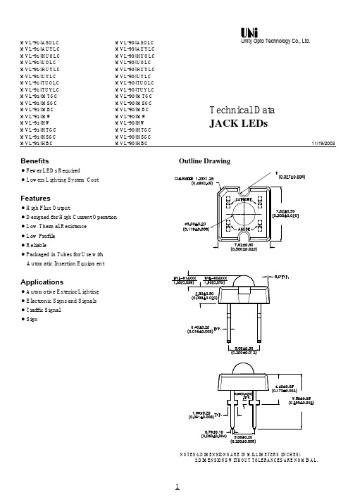
MVL-914ASOLC MVL-904ASOLC MVL-914AUYLC MVL-904AUYLC MVL-914HUOLC MVL-904HUOLC MVL-914UOLC MVL-904UOLC MVL-914HUYLC MVL-904HUYLC MVL-914UYLC MVL-904UYLC MVL-914TUOLC MVL-904TUOLC MVL-914TUYLC MVL-904TUYLC MVL-914MTGC MVL-904MTGC MVL-914MSGC MVL-904MSGC MVL-914MBC MVL-904MBC MVL-914MW MVL-904MW MVL-914HW MVL-904HW MVL-914HTGC MVL-904HTGC MVL-914HSGC MVL-904HSGC MVL-914HBC MVL-904HBC11/19/2003BenefitsOutline Drawingl Fewer LEDs Required lFeaturesl High Flux Outputl l l Low Profile l Reliablel Applicationsl l l Traffic Signal l SignUnity Opto Technology Co., Ltd.Technical Data JACK LEDsNOTES:1.DIMENSIONS ARE IN MILLIMETERS (INCHES).2.DIMENSIONS WITHOUT TOLERANCES ARE NOMINAL.Device Selection Guideo MVL-914MBC MVL-904MBC MVL-914MTGC MVL-904MTGC MVL-914MSGC MVL-904MSGC MVL-914TUOLC MVL-904TUOLC MVL-914TUYLC MVL-904TUYLC View Angle 2θ1/2Part NumberMVL-914HUOLC MVL-904HUOLC 70(Degrees) Typ.50Total Flux φv (mlm) Typ.2500 @I F =70mA50703050506050 MVL-904HSGC MVL-914UOLC MVL-904UOLC MVL-914HUYLC MVL-904HUYLC MVL-914UYLC MVL-904UYLC MVL-914MW MVL-904MW MVL-914HW InGaN Signal GreenInGaN BlueMVL-914AUYLC MVL-914HBC MVL-904HBC MVL-914ASOLC MVL-904ASOLC 70AS (OMA) AlInGaP Red Orange 4000 @I F =70mATS AlInGaP Amber White InGaN True Green 1900 @I F =40mA InGaN True Green InGaN Signal GreenInGaN Blue White 3500 @I F =70mA 2000 @I F =40mA 85655070507070905070507070909070907085656050 MVL-904HW MVL-914HTGC MVL-904HTGC MVL-914HSGC MVL-904AUYLCAS (OMA) AlInGaP AmberTS AlInGaP Red AS AlInGaP Red-OrangeAS AlInGaP AmberLED Color4000 @I F =70mA 800 @I F =20mA 4000 @I F =40mA 1500 @I F =40mA 2000 @I F =20mA 1500 @I F =20mA 1200 @I F =20mA 1700 @I F =50mA 2500 @I F =70mA1700 @I F =50mA3500 @I F =70mAOptical Characteristics at T A =25o CColor,Lumious Viewing Peak Dominant Itensity Angle Part NumberWavelength Wavelength Total Flux2θ 1/2λpeak (nm)λd (nm)I V (mcd)/φv(mlm)(Degrees)Typ.Typ.Typ.Typ. MVL-914HUOLC 0.56070 MVL-904HUOLC 0.73650 MVL-914HUYLC 0.43770 MVL-904HUYLC 0.60850 MVL-914TUOLC 0.28190 MVL-904TUOLC 0.56070 MVL-914TUYLC 0.22890 MVL-904TUYLC 0.43770 MVL-914UOLC 0.56070 MVL-904UOLC 0.73650 MVL-914UYLC 0.56070 MVL-904UYLC 0.73650 MVL-914MTGC 0.59570 MVL-904MTGC 0.73050 MVL-914MSGC 0.45785 MVL-904MSGC 0.80465 MVL-914MBC 0.18785 MVL-904MBC 0.27065 MVL-914HTGC 0.59550 MVL-904HTGC 0.73030 MVL-914HSGC 0.45770 MVL-904HSGC 0.80450 MVL-914HBC 0.18770 MVL-904HBC 0.27050 MVL-914ASOLC 0.61590 MVL-904ASOLC 0.83570 MVL-914AUYLC 0.41290 MVL-904AUYLC0.56770Part NumberMVL-914MW MVL-904MW MVL-914HW MVL-904HWElectrical Characteristics at T A =25o CThermalDevice TypeResistance R θJ-PIN (o C/W)Min.Typ.Max Min.Typ.Typ.MVL-9X4HUOLC 1.83 2.2 2.79 MVL-9X4HUYLC MVL-9X4UOLC 1.83 2.15 2.79 MVL-9X4UYLC MVL-9X4TUOLC 2.072.53.15MVL-9X4TUYLC MVL-9X4ASOLC MVL-9X4AUYLC MVL-9X4MTGC 33.7 5.2MVL-9X4MSGC MVL-9X4MBC MVL-9X4MW MVL-9X4HTGC 33.74.0 MVL-9X4HSGC MVL-9X4HBC MVL-9X4HW125900 @I F =40mA @I F=70mA102010Voltage 5024681700 @I F =50mA 250900 @I F =40mA 600@I F =70mA 600@I F =70mA 600@I F =70mA 600@I F =50mA 600@I F =50mA 1900 @I F =40mA 1500 @I F =40mA Typ.2500 @I F =70mA Min.10600@I F =70mA 1000 @I F =40mA 2500 @I F =70mA 1700 @I F =50mA 3500 @I F =70mA 3500 @I F =70mA 2000 @I F =40mA Total Flux φv (mlm)200 @I F =20mA 1200 @I F =20mA 1500 @I F =70mA4000 @I F =70mA200 @I F =20mA 200 @I F =20mA Total Flux φv (mlm)630592@I F =40mA510640594630592523625590630592625590525505@I F =70mA Reverse Breakdown V R (Volts)@I R =100µA Forward V F (Volts)204000 @I F =40mA X Y 5054701500 @I F =20mA 523525502Chromaticity Coordinates (Typ.)800 @I F =20mA 4684701500 @I F =70mA 4000 @I F =70mA 62461590@I F =50mAMin.300 @I F =20mA2000 @I F =20mATyp.600 @I F =40mA 0.33 0.31 0.33 0.31@I F =20mA51090180180Thermal Resistance R θJ-A (o C/W)Typ.5945902502501201202000.51400425450475500525550575595620645670695MVL-9X4UYLC MVL-9X4HUYLC MVL-9X4TUYLCMVL-9X4AUYLC MVL-9X4UOLC MVL-9X4HUOLC MVL-9X4TUOLCMVL-9X4MTGC MVL-9X4HTGCMVL-9X4MSGC MVL-9X4HSGCMVL-9X4MBC MVL-9X4HGC0.00.10.20.30.40.50.60.70.80.91.001020304050607080R E L A T I V E I N T E N S I T Y102030405060701.2 1.62.0 2.4 2.83.2 3.64.0F O R W A R D C U R R E N T (m A )WAVELENGTH(nm)Figure 1.Relative Intensity vs.Wavelength.FORWARD VOLTAGE (V)Figure 2.Forward Current vs.Forwaard Voltage.R E L A T I V E L U M I N O U S F L U X (m A )FORWARD CURRENT(mA)Figure 3. RelativeLuminous Flux vs.Forward Current.M A X I M U M D C C U R R E N T (m A )01020304050607080020406080100120MBIENT TEMPERTURE (o C )Figure 4a. Maximum DC Forward Currentvs. Ambient Temperature.01020304050607080020406080100120MBIENT TEMPERTURE (o C )Figure 4b. Maximum DC Forward Currentvs. Ambient Temperature.M A X I M U M D C C U R R E N T (m A )MVL-9X4ASOLC0.10.20.30.40.50.60.70.80.91-100-80-60-40-20020406080100 OFF AXIS ANGLE (DEGREES)Figure 5. MVL-904HUOLC/MVL-904HUYLC/MVL-904UOLC/ MVL-904UYLC/MVL904MTGC/MVL-904HSGC/MVL-904MW MVL-904HW/MVL-904HBC/MVL-914HTGC Relative Luminous Intensity vs. Off Axis Angle.R E L A T I V E L U M I N O U S I N T E N S I T YR E L A T I V E L U M I N O U S I N T E N S I T Y OFF AXIS ANGLE (DEGREES)Figure 6. MVL-914HUOLC/MVL-914HUYLC/MVL-904TUOLC/ MVL-904TUYLC/MVL-914UOLC/MVL-914UYLC/ MVL-914MTGC/MVL-914HSGC/MVL-914HBC/ MVL-904ASOLC/MVL-904AUYLCRelative Luminous Intensity vs. Off Axis Angle.00.10.20.30.40.50.60.70.80.91-100-80-60-40-2002040608010000.10.20.30.40.50.60.70.80.91-100-80-60-40-20020406080100OFF AXIS ANGLE (DEGREES)Figure 7. MVL-904HTGCRelative Luminous Intensity vs. Off Axis Angle.R E L A T I V E L U M I N O U S I N T E N S I T Y R E L A T I V E L U M I N O U S I N T E N S I T Y OFF AXIS ANGLE (DEGREES)Figure 8. MVL-914TUOLC/MVL-914TUYLC/MVL-914ASOLC/MVL-914AUYLCRelative Luminous Intensity vs. Off Axis Angle.00.10.20.30.40.50.60.70.80.91-100-80-60-40-200204060801000.10.20.30.40.50.60.70.80.91-100-80-60-40-20020406080100OFF AXIS ANGLE (DEGREES)Figure 9. MVL-914MW/MVL-914HW Relative Luminous Intensity vs. Off Axis Angle.R E L A T I V E L U M I N O U S I N T E N S I T Y R E L A T I V E L U M I N O U S I N T E N S I T YOFF AXIS ANGLE (DEGREES)Figure 10. MVL-914MSGC/MVL-914MBCRelative Luminous Intensity vs. Off Axis Angle.0.10.20.30.40.50.60.70.80.91-100-80-60-40-200204060801000.10.20.30.40.50.60.70.80.91-100-80-60-40-20020406080100OFF AXIS ANGLE (DEGREES)Figure 9. MVL-904MSGC/MVL-904MBC Relative Luminous Intensity vs. Off Axis Angle.R E L A T I V E L U M I N O U S I N T E N S I T YPackaging Tubes of LEDsLEDs are packaged in tubes , each of which contains 60 LEDs.The LEDs in any individual tube come from a single category code.Figure 1. Shows a sample label taken from a tube.Boxes of LEDsEach box of LEDs contains 240 tubes , or 14400 LEDs.The box dimensions are 500× 243×150mm(L×W×H) All of the tubes are in the same orientation .Figure 2. Shows a sample label taken from a box .90mm。
- 1、下载文档前请自行甄别文档内容的完整性,平台不提供额外的编辑、内容补充、找答案等附加服务。
- 2、"仅部分预览"的文档,不可在线预览部分如存在完整性等问题,可反馈申请退款(可完整预览的文档不适用该条件!)。
- 3、如文档侵犯您的权益,请联系客服反馈,我们会尽快为您处理(人工客服工作时间:9:00-18:30)。
Package Dimensions
2 x 3mm RECTANGULAR SOLID
LAMPS
Features
1.LOW POWER CONSUMPTION.
2.ULTRA BRIGHTNESS IS AVAILABLE .
3.RELIABLE AND RUGGED.
4.EXCELLENT UNIFORMITY OF LIGHT OUTPUT.
5.SUITABLE FOR LEVEL INDICATOR.
6.LONG LIFE - SOLID STATE RELIABILITY.
Notes:
1. All dimensions are in millimeters (inches).
2. Tolerance is ±0.25(0.01") unless otherwise noted.
3. Lead spacing is measured where the lead emerge package.
4. Specifications are subject to change without notice.
E914Ix HIGH EFFICIENCY RED E914ED ORANGE
E914ET HIGH EFFICIENCY RED E914Gx GREEN E914Ax YELLOW E914PGT
PURE GREEN
Selection Guide
Description
The High Efficiency Red and Orange source color devices are made with Gallium Arsenide Phosphide on Gallium Phosphide Orange Light Emitting Diode.
The Green source color devices are made with Gallium Phosphide Green Light Emitting Diode.
The Yellow source color devices are made with Gallium Arsenide Phosphide on Gallium Phosphide Yellow Light Emitting Diode.
The Pure Green source color devices are made with Gallium Phosphide Pure Green Light Emitting Diode.
Note:
1. θ1/2 is the angle from optical centerline where the luminous intensity is 1/2 the optical centerline value.
.
o N t r a P r l g i t E o o C n t i m l
a i r e t a M +λ)
m n (D e
p y T s n e L )d c m (v I A
m 01@g i e i V n w e l g n A n M i .
p y T .
2θ2
/1D I 419E P a G /P s A a G 526D E S U F F I D D E R 28°001T I 419E P a G /P s A a G 526T N E R A P S N A R T D E R 38°09D E 419E P a G /P s A a G 526D E S U F F I D E G N A R O 28°001T E 419E P a G /P s A a G 526T N E R A P S N A R T E G N A R O 38°09D G 419E P a G 865D E S U F F I D N E E R G 26°001T G 419E P a G 865T N E R A P S N A R T N E E R G 38°09D A 419E P a G /P s A a G 885D E S U F F I D R E B M A 25°001T A 419E P a G /P s A a G 885T N E R A P S N A R T R E B M A 27°09T
G P 419E P
a G 5
55T
N E R A P S N A R T N E E R G 5
.01
°
09
Electrical / Optical Characteristics at T A =25°C
Absolute Maximum Ratings at T A =25°C
Notes:
1. 1/10 Duty Cycle, 0.1ms Pulse Width.
2. 4mm below package base.
l
o b m y S r
e t e m a r a P e
c i v e D .p y T x a .
M U s
t i n n o i i d n o C t e T t s s
λk a e p h t g n e l e v a W k a e P d e R y c n e i c i f f E h g i H e g n a r O n e e r G w
o l l e Y n
e e r G e r u P 726726565095555m n I F A
m 02=λD h t g n e l e v a W e t a n i m o D d e R y c n e i c i f f E h g i H e g n a r O n e e r G w
o l l e Y n
e e r G e r u P 526526865885555m n I F A
m 02=λ∆2
/1e n i L l a r t c e p S h
t d i w f l a H d e R y c n e i c i f f E h g i H e g n a r O n e e r G w
o l l e Y n
e e r G e r u P 5454035303m n I F A
m 02=C e c n a t i c a p a C d e R y c n e i c i f f E h g i H e g n a r O n e e r G w
o l l e Y n
e e r G e r u P 5151510254F p V F z
H M 1=f ;V 0=V F e g a t l o V d r a w r o F d e R y c n e i c i f f E h g i H e g n a r O n e e r G w
o l l e Y n e e r G e r u P 0.20.20.21.25
2.25.25.25.25.25.2V I F A
m 02=I R t n e r r u C e s r e v e R l
l A 01A u V R V
5=r e t e m a r a P y
c n e i c i f f E h g i H d
e R e g n a r O n e e r G w e Y l l o e e r P n
e r G u U s t i n n o i t a p i s s i d r e w o P 501501501501501W m t n e r r u C d r a w r o F C D 0303520352A m ]1[t n e r r u C d r a w r o F k a e P 061061041041531A m e
g a t l o V e s r e v e R 5
5
5
5
5
V
e r u t a r e p m e T e g a r o t S /g n i t a r e p O 04-°58+o T C °C ]
2[e r u t a r e p m e T g n i r e d l o S d a e L 062°s
d n o c
e S 5r o F C。
