MCR-E-01A HIGH VOLTAGE CABLE高压电缆 Rev0
KVV线缆参数规格
KVV数据电缆是我厂主要产品之一,我厂是生产和销售KVV线生产公司的制造商之一。
如果想购买我厂KVV线生产公司请联系我厂销售部。
KVV通讯电缆参数,KVV通讯电缆执行标准,KVV通讯电缆结构,KVV通讯电缆性能,KVV通讯电缆知识,KVV通讯电缆价格RS-485通讯电缆特性阻抗为120欧姆智能电表抄表专用线--RS-485通讯电缆亚太线缆是严格按RS-485通讯协议规定设计生产的产品。
产品性能卓越,广泛应用于复杂的工业自动化控制网络及楼宇自控网络KVV通讯线在一般场合采用双绞线就可,但在要求较高的环境下KVV要采用带屏蔽层的双绞电缆。
使用KVV通讯线时,KVV对于特定的传输线路,主KVV机(召测设备)到仪表的485口间的电缆长度与数据信号传输的波特率成反比;这个长度主要受信号的失真以及噪声的影响所影响。
KVV理论上KVV通信电缆的传输距离能达到1200米,但实际应用中KVV传输距离要小于1200米,KVV具体长度受周围的环境影响。
KVV通信电缆特点:RS-485通讯电缆特性阻抗为120欧姆,导体为2*24AWG多股绞合镀锡铜丝,PE绝缘介质,由铝箔/聚酯复合带100%覆盖+镀锡铜丝90%覆盖共2层屏蔽,附有独立接地导线,KVV工业灰色PVC外护套。
KVV数据电缆 RS48通信电缆KVV第一屏蔽:铝箔屏蔽引流线:多股绞合镀锡铜网线, 每股7支, KVV每支导体线径为0.30mm, 共一股, 外径: 0.91 +/- 0.03mmKVV第二屏蔽:铝镁编织网屏蔽, 覆盖率为55%KVV内护套:黑色PVC, OD: 8.0mm +/- 10%经测试KVV通讯线最大的通信距离约为1219M,KVV最大传输速率为10Mb/S,KVV传输速率与传输距离成反比,KVV在100Kb/S的传输速率下,KVV才能达到最大的通信距离,如果需传输更长的距离,需要加485中继器。
KVV总线一般最大支持32个节点,如果使用特制的485芯片,可以达到128个或者256个节点,最大的可以支持到400个节点。
EY系列1200瓦特高压DC电源1kV-60kV机械式安装3.5英寸面板高度实验室性能CE和半导体S
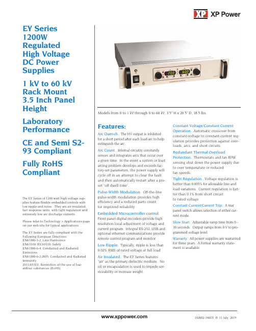
EY Series 1200W Regulated High Voltage DC Power Supplies1 kV to 60 kV Rack Mount 3.5 Inch Panel HeightLaboratory PerformanceCE and Semi S2-93 Compliant Fully RoHS CompliantThe EY Series of 1200 watt high voltage sup-plies feature flexible embedded controls with low ripple and noise. They are air insulated, fast response units, with tight regulation and extremely low arc discharge currents.Please refer to Technology > Applications page on our web site for typical applications.The EY Series are fully compliant with the Following European Directives:EN61000-3-2, Line HarmonicsEN61010/ IEC61010, SafetyEN61000-6-4, Conducted and Radiated EmissionsEN61000-6-2:2005, Conducted and Radiated Immunity2011/65/EU, Restriction of the use of haz-ardous substances (RoHS).Features:Arc Quench. The HV output is inhibitedfor a short period after each load arc to helpextinguish the arc.Arc Count. Internal circuitry constantlysenses and integrates arcs that occur overa given time. In the event a system or loadarcing problem develops and exceeds fac-tory-set parameters, the power supply willcycle off in an attempt to clear the faultand then automatically restart after a pre-set “off dwell time”.Pulse-Width Modulation.Off-the-linepulse-width modulation provides highefficiency and a reduced parts countfor improved reliability.Embedded Microcontroller control.Front panel digital encoders provide highresolution local adjustment of voltage andcurrent program. Integral RS-232, USB andoptional ethernet communications provideremote control program and monitor.Low Ripple.Typically, ripple is less than0.02% RMS of rated voltage at full load.Air Insulated. The EY Series features“air” as the primary dielectric medium. Nooil or encapsulation is used to impede ser-viceability or increase weight.Constant Voltage/Constant CurrentOperation. Automatic crossover fromconstant-voltage to constant-current reg-ulation provides protection against over-loads, arcs, and short circuits.Redundant Thermal OverloadProtection.Thermostats and fan RPMsensing shut down the power supply dueto over temperature or reducedfan speeds.Tight Regulation.Voltage regulation isbetter than 0.005% for allowable line andload variations.Current regulation is bet-ter than 0.1% from short circuitto rated voltage.Constant Current/Current Trip. A rearpanel switch allows selection of either cur-rent mode.Slow Start. Adjustable ramp time from 0 -30 seconds. Output ramps from 0 V to pro-grammed voltage level.Warranty. All power supplies are warrantedfor three years. A formal warranty state-ment is available.Models from 0 to 1 kV through 0 to 60 kV, 3.5” H x 20.5” D, 18.5 lbs.Stability:0.01% per hour after 1/2 hour warm-up, 0.05% per 8 hours.Voltage Rise/Decay Time Constant:The voltage rise time constant is 50 ms typical for all models using either HV enable or remote programming control.The voltage decay time constant is 50ms with a 10% resistive load. Temperature Coefficient:0.01% /°C.Ambient Temperature:-20 to +40° C, operating; -40 to +85° C, storage.Polarity: Available with either positive,negative or hardware configurable reversable polarity with respect to chassis ground.Protection:Automatic current regulation protects against all overloads, including arcs and short circuits. Thermal switches and RPM sensing fans protect against thermal overload. Fuses, surge-limitingresistors, and low energy components provide ultimate protection.Arc Quench:An arc quench feature provides sensing of each load arc and quickly inhibits the HV output for approximately 20 ms after each arc. Standard on 8 - 60 kV models;optional on 1- 6 kV models.Arc Count:Internal circuitry senses the number of arcs caused by external load discharges. If the rate of consecutive arcs exceeds approximately one arc per second for five arcs, the supply will turn off for approximately 5 seconds to allow clearance of the fault. After this period the supply will automatically return to the programmed kV value with the rise time constant indicated.If the load fault still exists, the above cycle will repeat. Standard on 8 - 60 kV models; optional on 1- 6 kV models.External Interlock:Open = off,closed = on. Normally latching except for blank front panel version where it is non-latching.Remote HV Enable/Disable: 0 - 1.5 V = OFF, 2.5 - 15 V = ON.RS232/USB/Ethernet Programming and Monitor Accuracy:Resolution:0.025% of full scale for both the voltage and the current programs. 0.1% of full scale for both the voltage and the current monitorsSpecifications(Specifications apply from 5% to 100%rated voltage. Operation is guaranteed down to zero voltage with a slight degradation of performance.)Input:180 to 264 VRMS single-phase,48-63 Hz, 1500 VA maximum at full load. C14 connector per IEC 60320with mating line cord.Efficiency: Typically greater than 85%at full load.Power Factor: > 0.995.Output:Continuous, stable adjust-ment, from 0 to rated voltage or cur-rent by panel mounted optical rotary encoder or by external +10V signals.Voltage accuracy is 0.5% of setting +0.2% of rated. Optical rotary encoder resolution: 0.025% with "FineAdjustment" mode selected. 0.25%with "Coarse Adjustment" mode (default). Repeatability is < 0.1% of rated.Static Voltage Regulation: Better than ±0.005% for specified line variations and 0.005% + 0.5 mV/mA for no load to full load variations.Dynamic Voltage Regulation:For load transients from 10% to 99% and 99% to 10%, typical deviation is less than 2% of rated output voltage with recovery to within 1% in 500 us and recovery to within 0.1% in 1 ms.Ripple:Better than 0.02% of rated voltage + 0.5 V RMS at full load. Current Regulation:When in current regulation mode, better than 0.1% from short circuit to rated voltage at any load condition.Voltage Monitor:0 to +10 V equivalent to 0 to rated voltage.Accuracy: 0.5% of reading + 0.2% of rated. Impedance is 10 K W .Current Monitor:0 to +10 V equivalent to 0 to rated current. Accuracy: 1% of reading + 0.1% of rated. Impedance is 10 K W .Remote setting accuracy:Voltage setting accuracy is better than 0.5%of setting + 0.2% of rated. Remote reading accuracy:Voltage reading accuracy is 0.5% of reading + 0.2% of rated. Current reading accuracy is 1% of reading + 0.1% of rated.Front Panel Elements.Output Voltage & Current Display:3.5 Digit digital meters. 1250 count maximum.Indicators:AC Power, Current Mode, Voltage Mode, Pol +, Pol -,Fault, Fine Adjustment, Preset,Control Lock, Remote Enable,Remote Program, HV On.AC Power:Rocker switchSwitches (momentary):HV On,SS Slope, Standby, Remote Enable,Remote Program, Preset, Fine Adjust, Control Lock.Rotary Encoders:Voltage Adjust,Current Adjust.Rear Panel Elements . AC power entry connector, fuses, power on indicator, ground stud, HV output connector,remote interface connector, RS232/USB connectors.The signals provided on the remote interface connector are as follows: Inputs:Safety interlock, output voltage and current program signals, high voltage enable and remote HV on.Outputs:Output voltage andcurrent monitor signals, HV status,fault status, I/V mode status and a +10 V reference source.Signal common and ground reference terminals are also provided.Accessories:Detachable, 8 foot,shielded high voltage coaxial cable (see models chart for cable type),6 foot NEMA 6-15 line cord, 10 foot null modem cable and 10 foot USB cable are provided.Weight:Approximately 18.5 lbs.Options (contact sales for details)Symbol DescriptionNC Blank front panel, power switch and indicator only. ZR Zero start interlock. Voltage control, local or remote, must be at zero before the HV will enable.5VC 0-5 V voltage and current program/monitor.ARC Arc count and quench as described in thespecifications for 1 - 6 kV models.AC Arc Count OnlyAQ Arc Quench OnlyETH Virtual RS-232 COM port over Ethernet network. (Requires compatible OS (eg Windows) for COM drivers)Models。
欧姆龙CJ1W-MD211模块使用说明和程序案例

计算机电缆标准

RVB铜芯聚氯乙烯平型连接电线
RVS铜芯聚氯乙烯绞型连接电线
RVV铜芯聚氯乙烯绝缘聚氯乙烯护套圆形连接软电缆
ARVV镀锡铜芯聚氯乙烯绝缘聚氯乙烯护套平形连接软电缆
RVVB铜芯聚氯乙烯绝缘聚氯乙烯护套平形连接软电缆
RV-105铜芯耐热105oC聚氯乙烯绝缘聚氯乙烯绝缘连接软电缆
NH—耐火型
WDZ—无卤低烟阻燃型
WDN—无卤低烟耐火型
例如:
SYV 75-5-1(A、B、C)
S:射频Y:聚乙烯绝缘V:聚氯乙烯护套A:64编B:96编C:128编
75:75欧姆5:线径为5MM 1:代表单芯SYWV 75-5-1
S:射频Y:聚乙烯绝缘W:物理发泡V:聚氯乙烯护套
75:75欧姆5:线缆外径为5MM 1:代表单芯来源:输配电设备网
其客户群涉及:政府机关、国家电网、系统集成商、通信运营商和跨国公司,服务亚太地区电力基础设施,光电通信设施等为用户提供完善的产品和服务。
凭借着“科技至上、品质至上,团队至上,服务至上”的理念,成为全球电缆通讯行业的领先品牌,并拥有实力雄厚的产品设计研发团队,系统方案解决团队,供应链管理团队以及市场营销团队。
矿用信号电缆……………………………………………………………………………39
信号电缆…………………………………………………………………………………42
射频电缆…………………………………………………………………………………44
补偿导线、电缆…………………………………………………………………………46
塑料绝缘安装屏蔽电线、电缆…………………………………………………………47
NH-ZR-YJS-C交联聚乙烯绝缘无卤低烟、阻燃热塑性聚烯烃衬垫(或护层)耐火型电力电缆
美国电缆有限公司 Eaton 168801 产品说明说明书

Eaton 168801Eaton Moeller® series MSC-DE DOL starter, 380 V 400 V 415 V: 0.37 kW, Iq= 100 kA, Ir= 0.3 - 1.2 A, 24 V DC, DC Voltage, Screw terminalsGeneral specificationsEaton Moeller® series MSC-DE DOL starter168801MSC-DE-1,2-M17(24VDC)4015081652921128 mm 242 mm 45 mm 1.1 kgVDE 0660 IEC/EN 60947-4-1Product NameCatalog Number Model CodeEANProduct Length/Depth Product Height Product Width Product Weight Certifications1.2 AIs the panel builder's responsibility. The specifications for the switchgear must be observed.1.1 kW230 - 415 V AC0 A0 VMeets the product standard's requirements.Is the panel builder's responsibility. The specifications for the switchgear must be observed.DIN rail≤ 500 ms, main conducting paths, AC-4 cycle operationDoes not apply, since the entire switchgear needs to be evaluated.0 kW0 kWMeets the product standard's requirements.24 VShort-circuit release Save time and space thanks to the new link module PKZM0-XDM32ME Simple, flexible and safe! Distribution system for motor-starter combinationsMotor Starters in System xStart - brochureProduct Range Catalog Switching and protecting motorsDA-DC-00004109.pdfDA-DC-00004245.pdfeaton-manual-motor-starters-dol-starter-msc-d-dimensions.epseaton-manual-motor-starters-dol-starter-msc-d-3d-drawing-002.eps eaton-general-ie-ready-dilm-contactor-standards.epseaton-manual-motor-starters-mounting-msc-d-dol-starter-3d-drawing.eps DA-CE-ETN.MSC-DE-1,2-M17(24VDC)IL03402010ZWIN-WIN with push-in technologyDA-CS-msc_de_bg2DA-CD-msc_de_bg2eaton-manual-motor-starters-device-msc-d-dol-starter-wiring-diagram.epsRated operational current for specified heat dissipation (In) 10.11 Short-circuit ratingRated operational power at AC-3, 380/400 V, 50 Hz Rated operational voltageRated conditional short-circuit current, type 1, 480 Y/277 V Rated control supply voltage (Us) at AC, 50 Hz - min10.4 Clearances and creepage distances10.12 Electromagnetic compatibilityMounting methodCut-out periods - min10.2.5 LiftingRated power at 575 V, 60 Hz, 3-phaseRated power at 460 V, 60 Hz, 3-phase10.2.3.1 Verification of thermal stability of enclosures Rated control supply voltage (Us) at DC - minFitted with:BrochuresCatalogs Certification reports DrawingseCAD model Installation instructions Installation videos mCAD modelWiring diagramsCurrent flow times - min700 (Class 10) AC-4 cycle operation, Main conducting paths 1000 (Class 20) AC-4 cycle operation, Main conducting paths 500 (Class 5) AC-4 cycle operation, Main conducting paths 900 (Class 15) AC-4 cycle operation, Main conducting paths Note: Going below the minimum current flow time can cause overheating of the load (motor).For all combinations with an SWD activation, you need not adhere to the minimum current flow times and minimum cut-out periods.Number of pilot lightsShort-circuit current rating (high fault at 600 V)1 A, Class J/CC, max. Fuse, SCCR (UL/CSA)100 kA, Fuse, SCCR (UL/CSA)Rated control supply voltage (Us) at AC, 50 Hz - max0 VCoordination type210.8 Connections for external conductorsIs the panel builder's responsibility.Coordination class (IEC 60947-4-3)Class 2Rated conditional short-circuit current, type 1, 600 Y/347 V0 AAmbient operating temperature - max55 °CRated operational power at AC-3, 220/230 V, 50 Hz0.18 kWConnection to SmartWire-DTNoNumber of command positionsStatic heat dissipation, non-current-dependent Pvs0.86 WElectrical connection type of main circuitScrew connectionRated conditional short-circuit current (Iq), 500 V10 AElectrical connection type for auxiliary- and control-current circuit Screw connectionPower consumption (sealing) at DC0.86 WRated control supply voltage (Us) at DC - max24 V10.9.3 Impulse withstand voltageIs the panel builder's responsibility.Ambient operating temperature - min-25 °C10.6 Incorporation of switching devices and componentsDoes not apply, since the entire switchgear needs to be evaluated.10.5 Protection against electric shockDoes not apply, since the entire switchgear needs to be evaluated.ClassAdjustable10.13 Mechanical functionThe device meets the requirements, provided the information in the instruction leaflet (IL) is observed.10.2.6 Mechanical impactDoes not apply, since the entire switchgear needs to be evaluated.10.9.4 Testing of enclosures made of insulating materialIs the panel builder's responsibility.10.3 Degree of protection of assembliesDoes not apply, since the entire switchgear needs to be evaluated.Heat dissipation per pole, current-dependent Pvid0.4 WActuating voltage24 V DCVoltage typeDCSwitching capacity (auxiliary contacts, general use)1 A, 250 V DC, (UL/CSA)15 A, 600 V AC, (UL/CSA)Overload release current setting - min0.3 AEquipment heat dissipation, current-dependent Pvid1.2 WHeat dissipation capacity Pdiss0 WRated operational current (Ie)1.2 ASuitable forAlso motors with efficiency class IE3Number of auxiliary contacts (normally closed contacts)Rated conditional short-circuit current (Iq), type 2, 380 V, 400 V, 415 V100000 A10.2.3.2 Verification of resistance of insulating materials to normal heatMeets the product standard's requirements.10.2.3.3 Resist. of insul. mat. to abnormal heat/fire by internal elect. effectsMeets the product standard's requirements.Rated operational power at AC-3, 500 V, 50 Hz0.37 kWOverload release current setting - max1.2 A10.9.2 Power-frequency electric strengthIs the panel builder's responsibility.Overvoltage categoryIIIDegree of protectionIP00NEMA OtherPollution degree3Rated control supply voltage (Us) at AC, 60 Hz - min0 V10.7 Internal electrical circuits and connectionsIs the panel builder's responsibility.Rated impulse withstand voltage (Uimp)6000 V ACConnectionScrew terminals10.10 Temperature riseThe panel builder is responsible for the temperature rise calculation. Eaton will provide heat dissipation data for the devices.FunctionsTemperature compensated overload protectionRated operational current (Ie) at AC-3, 500 V0.9 ARated conditional short-circuit current (Iq), type 2, 230 V 100000 ATypeStarter with electronic trip unit10.2.2 Corrosion resistanceMeets the product standard's requirements.10.2.4 Resistance to ultra-violet (UV) radiationMeets the product standard's requirements.10.2.7 InscriptionsMeets the product standard's requirements.Short-circuit release (Irm) - max186 ARated control supply voltage (Us) at AC, 60 Hz - max0 VRated operational current (Ie) at AC-3, 380 V, 400 V, 415 V 1.2 AModelDirect starterNumber of auxiliary contacts (normally open contacts)1Switching capacity (auxiliary contacts, pilot duty)A600, AC operated (UL/CSA)P300, DC operated (UL/CSA)Eaton Corporation plc Eaton House30 Pembroke Road Dublin 4, Ireland © 2023 Eaton. All Rights Reserved. Eaton is a registered trademark.All other trademarks areproperty of their respectiveowners./socialmedia。
DCR-11350高压电缆组件要求-奔驰汽车-已转换
奔驰高压线束电缆组件要求1范围该标准定义了 AHS -C HEV 中使用的高压布线组件的特性,要求,功能,性能和验证。
设计和操作必须符合所有适用的法规和法律。
该标准涵盖了仅用于 AHS -C HEV 的高压电缆组件的操作,可靠性,耐用性,质量和最严格的要求。
高压电线电缆组件应为以下设备提供电力传输:★通过六条单独的电缆,从电力电子盒(PEB)向两个电动马达 EM -A 和 EM -B 提供高压三相交流电(AC)。
★在一个成组的接线电缆中通过三芯从 PEB 向油电动泵(EMP)提供高压三相交流电★通过两条单独的电缆,从电池组向 PEB 提供 HV 直流电(DC)。
★通过两条单独的电缆将高压直流电从高压配电箱(HVPDB)提供给电动空调(EAC)压缩机。
2缩写,首字母缩写词,定义和符号AC: Alternating Current 交流电DC: Direct Current 直流电DV: Design Verification 设计验证DVP: Design Verification Plan 设计验证计划DVP&R: Design Verification Plan&Report 设计验证计划和报告EAC: Electric Conditioning Compressor 电子空调压缩机EMP: Electric Motor Pump 油电动泵EM: Electric Motors 电动马达HEV: Hybrid Electric Vehicle 混合动力电动汽车HV: High Voltage-Voltage levels greater than 30 VAC or 60 VDC 高于 30 VAC 或 60 VDC 的高压等级HVPDB: High Voltage Power Distribution Box 高压配电箱PEB: Power Electronics Box 电力电子箱PETC: Powered Thermal Cycle Endurance 动力热循环耐久性RMS. Root -Mean –Square 均方根OEM: Original Equipment Manufacturer 主机厂3测试要求,特殊测试设备和测试条件3.1测试要求供应商必须对本规范文档中列出的所有测试证明 100%成功。
中压电缆标准
中压电缆标准
一、什么是中压单芯电缆?
中压单芯电缆是一种常用的电缆,主要用于局部配电和电气设备连接。
它由导体、绝缘层、包覆层和护套组成。
中压单芯电缆的额定电压一般在1KV以上,但低于35KV。
二、中压单芯电缆标准
中压单芯电缆的生产和使用需要遵守一系列标准,包括国际标准、欧洲标准、美国标准和中国标准等。
以下是几种主要的中压单芯电缆标准:
1. 国际标准:IEC 60502-2
2. 欧洲标准:EN 50525-2-11
3. 美国标准:ICEA S-93-639
4. 中国标准:GB/T 12706.2-2008
三、中压单芯电缆标准对于电缆选择和使用的指导作用
中压单芯电缆标准明确了电缆的技术要求、试验方法和质量控制要求,为电缆的生产、选择和使用提供了指导作用。
在购买中压单芯电缆时,可以根据标准的要求选择符合自己需要的电缆。
同时,在电缆使用过程中,可以参考标准的试验方法进行质量检测,保障电缆的安全和可靠性。
四、结论
中压单芯电缆标准是电缆生产和使用过程中的重要参考依据。
选择符合标准要求的电缆,可以保障电缆的安全和可靠性,同时降低维护和更换的成本。
西安特尔电源中国有限公司MVS中高压空缆断路器产品介绍说明书

13
12 kV and 17,5 kV family W-VACi fixed version
476 mm 629 mm 676 mm
440 mm
Pole space 150 mm
Cubicle width: 600 mm
630 A - 25 kA
1250 A - 31.5 kA
588 mm
Pole space 210 mm
Optional Accessories
Second shunt opening release (SO2)
Undervoltage release
9
9
W-VACi Product portfolio overview
10
10
W-VACi vacuum circuit breaker family
Withdrawable
Fixed
11
11
12 kV and 17,5 kV family W-VACi withdrawable version
- Pictures are representative.
- Not all breaker configurations shown. For detailed drawings of all available breaker sizes, please conta1c2t your Eaton representative.
Cubicle width: 800 mm
2000 A - 40 kA
770 mm Pole space 275 mm
Cubicle width: 1000 mm
3150 A / 4000 A* - 50 kA
高压电缆电压标准
高压电缆电压标准
高压电缆电压标准是指电缆可以承受的最大电压。
具体的高压电缆电压标准在不同国家和地区可能有所不同,下面列举一些常见的高压电缆电压标准:
1. 欧洲标准:根据欧洲标准,高压电缆的电压可以分为以下几个等级:
- 低电压(LV):额定电压不超过1000V。
- 中等电压(MV):额定电压在1000V 到 36 kV之间。
- 高电压(HV):额定电压在36 kV 到 230 kV之间。
- 超高电压(UHV):额定电压超过230 kV。
2. 美国标准:根据美国标准,高压电缆的电压可以分为以下几个等级:
- 低电压(LV):额定电压不超过600V。
- 中等电压(MV):额定电压在600V 到 35 kV之间。
- 高电压(HV):额定电压在35 kV 到 230 kV之间。
- 超高电压(UHV):额定电压超过230 kV。
需要注意的是,这只是一些常见的高压电缆电压标准,具体电压等级可能会根据不同的应用领域和需求而有所变化。
另外,高压电缆的设计和制造也需要符合国家和地区的相关标准和规范。
ABB 变频器用中压电力电缆样本

ABB 变频器用中压电力电缆样本ABB 变频器用中压电力电缆样本1. 引言ABB 变频器是一种使用广泛的电力传动设备,它在工业生产中起到了重要的作用。
作为变频器的关键组成部分之一,中压电力电缆在变频器的运行中起到了重要的传输电能的作用。
本文将介绍ABB 变频器用中压电力电缆的样本,包括其定义、特点以及应用。
2. 定义中压电力电缆是一种用于变频器的电力传输电缆,其额定电压范围为1kV至35kV。
它具有较高的绝缘能力、耐腐蚀性和耐磨性,能够稳定传输高功率的电能。
3. 特点ABB 变频器用中压电力电缆具有以下特点:- 高绝缘能力:中压电力电缆采用优质绝缘材料,能够有效隔离电力传输过程中的杂散电流,提高系统的安全性和可靠性。
- 良好的耐腐蚀性:中压电力电缆采用防腐材料作为外层护套,能够在潮湿、高温、酸碱等恶劣环境下正常运行,延长其使用寿命。
- 耐磨性强:中压电力电缆外层护套采用耐磨材料,能够在机械摩擦和挤压中保护内部电缆结构,提高电缆的耐久性。
- 低损耗:中压电力电缆采用高导电材料制造,能够减小电能传输过程中的能量损耗,提高电力利用效率。
4. 应用ABB 变频器用中压电力电缆广泛应用于以下领域:- 工业生产:中压电力电缆被广泛用于各类工业生产系统和设备中,如电机驱动系统、输送带等。
- 发电厂:中压电力电缆用于发电厂内各类发电设备的电力传输,确保安全可靠的电能输送。
- 城市建设:中压电力电缆用于城市建设中的公共设施,如地铁、桥梁、道路照明等。
5. 结论ABB 变频器用中压电力电缆是一种高性能的电力传输电缆,具有高绝缘能力、良好的耐腐蚀性和耐磨性。
它广泛应用于工业生产、发电厂和城市建设等领域。
在使用中,需要注意正确的安装和维护,以确保其正常运行和延长使用寿命。
> 注:本文档以 Markdown 格式输出,不包含图片和表格。
请根据实际情况,进行相关文档的补充和修改。
美国爱本斯公司高压地下电缆终端设备的CA650003EN版产品说明说明书
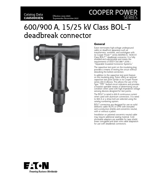
GeneralEaton terminates high-voltage underground cable on deadfront apparatus such astransformers, switches, and switchgear with its Cooper Power E series 600/900 A, 15/25 kV Class BOL -T E deadbreak connector. It is fully shielded and submersible and meets the requirements of IEEE T Std 386E -2016—“Separable Insulated Connector Systems.”The capacitive test point on the insulating plug provides a means of testing the circuit without disturbing the bolted connection.In addition to the capacitive test point feature on the insulating plug, Eaton offers an optional capacitive test point similar to its Cooper Power series 200 A elbows. This allows the use of the Type “TPR” faulted circuit indicators and provides a hotstick operable means of determining circuit condition when used with high-impedance voltage sensing devices designed for test points.The BOL -T is rated to 600 A continuous current when used with aluminum connectors. It is rated to 900 A or a shear bolt are selected using the catalog numbering system.BOL -T connectors are designed for use on solid dielectric cable (XLPE or EPR) with extruded semi-conductive shields and concentric neutral, with or without a jacket.Installation on jacketed concentric neutral cable may require additional sealing material. Cold shrinkable adapters are available for tape shield, linear corrugated and drain wire cable adaptation for use with deadbreak connectors.600/900 A, 15/25 kV Class BOL-Tdeadbreak connector2Catalog Data CA650003ENEffective June 2023600/900 A, 15/25 kV Class BOL -Tdeadbreak connectorEATON 900 A ratingThe BOL -T connector is rated for 900 A continuous when used with a coppertop compression connector or shear bolt, copper insulating plug, copper stud, and copper bushing or junction. If a 900 A rating is desired, specify a “C ” as the 10th digit when determining the part number. See Step 3 on page 5.InterchangeabilityEaton’s Cooper Power series 600 A deadbreak connectors conform to the electrical, mechanical, and dimensional requirements ofIEEE Std 386-2016. The connectors can be used on any comparably rated bushing interface that also meets the requirements of this standard. In addition, all cable adapters, insulating plugs,compression connectors, and other component parts are designed to be interchangeable with those currently available from other major manufacturers that also comply with IEEE Std 386-2016.InstallationA torque wrench and 1-inch socket are used to tighten theinsulating plug through the compression or shear bolt connector within the T -body onto a de-energized 600 A bushing interface. Refer to Service Information MN650005EN 600 A 15/25 kV Class BOL -T and Separable Splice Connector Assembly Installation Instructions for details.Production testsTests conducted in accordance with IEEE Std 386-2016:•ac 60 Hz 1-minute withstand • 40 kV•Minimum partial discharge extinction voltage • 19 kVTests conducted in accordance with Eaton re q uire m ents:• Physical in s pec t ion • Periodic dissection •Periodic X-ray analysisT able 1. Voltage ratings and characteristicsDescriptionkVStandard voltage class25Maximum rating phase-to-ground 15.2ac 60 Hz 1-minute withstand 40dc 15-minute withstand 78BIL and full wave crest125Minimum partial discharge extinction voltage 19ote: N Voltage ratings and characteristics are in accordance with IEEE Std 386-2016.T able 2. Current ratings and characteristicsDescriptionAmperesContinuous 600 A rms (aluminum)900 A rms (copper or shear bolt)4-hour overload900 A rms (aluminum)1200 A rms (copper or shear bolt)Short time (aluminum)40,000 A rms symmetrical for 0.17 s 27,000 A rms symmetrical for 4 s Short time(copper or shear bolt)40,000 A rms symmetrical for 0.17 s 27,000 A rms symmetrical for 4 sote: N Current ratings and characteristics are in ac c or d ance with IEEE Std 386-2016.3Catalog Data CA650003ENEffective June 2023600/900 A, 15/25 kV Class BOL -T deadbreak connector EATON Features and benefitsFigure 1. BOL -T cutaway design featuresote: N Dimensions are in inches (mm) and are for reference only.4Catalog Data CA650003ENEffective June 2023600/900 A, 15/25 kV Class BOL -Tdeadbreak connectorEATON Optional featuresCoppertop compression connectorsCoppertop compression connectors (aluminum sleeve welded toa copper spade) provide a high-conductivity material in a boltedconnection and are compatible with aluminum or copper conductors.Shear bolt connectorsBolted cable lug is fitted with stepless bolts, which shear offwhen optimum contact force has been reached. Provide electrical continuity for copper and aluminum conductors while eliminating need for dies and compression tools.Shear bolt connectorAll copper current pathA full copper current-carrying path can be obtained by specifying a coppertop compression connector, copper stud, and copperinsulating plug.Figure 2. BOL -T stacking dimensions in inches (mm)Ordering informationEach BOL -T connector kit contains:• Molded rubber T -body • Insulating plug • Insulating plug cap• Compression or shear bolt connector • Cable adapter • Silicone lubricant•Installation instruction sheetTo order a 15/25 kV Class BOL -T connector kit, see following Steps 1–5 to build the catalog number.BOL -T connector kit—catalog numbering systemBuild the 12-digit catalog number for a BOL -T kit by following the steps given below. The first 5 digits are “BT625”, so only digits 6 through 12 need to be selected.123456789101112BT625Catalog number digits:1 and2 — “BT ” = BOL -T connector system3 — “6” = 600 A system4 and5 — “25” = 25 kV class bushing interfaceStep 1. Select digits 6 and 7 cable adapter range code Determine the cable’s diameter over the electrical insulation as shown in Figure 3 (including tolerances).Then identify a cable range from T able 3 that covers the minimum and maximum insulation diameters.Select the correct cable adapter range code from T able 3.T able 3. Cable diameter rangeInchesmmCable adapter range code0.61–0.9715.5–24.6AB 0.75–1.0819.1–27.4CC 0.97–1.3124.6–33.3DD 1.09–1.4727.7–37.3EE 1.26–1.6432.0–41.7FF 1.36–1.7134.5–43.4GG 1.51–1.8538.4–47.0HH 1.70–1.9743.2–50.0JJ5Catalog Data CA650003ENEffective June 2023600/900 A, 15/25 kV Class BOL -T deadbreak connector EATON Step 2. Select digits 8 and 9 conductor codeIdentify the conductor size and type in T able 4 (compression) or T able 5 (shear bolt) and select the conductor code from the appropriate column.T able 4. Compression connectorConcentric or compressed Compact or solid Conductor codeAWG or kcmilmm 2AWG or kcmilmm 2No connector 00#2351—11#1—1/050121/0502/070132/0703/0—143/0—4/095154/09525012016250120300—17300—350—18350—40018519400185450—20450—5002402150024060030022600300700—23650—750—24750—900—25900—1000500261000500——2712506301250—28T able 5. Shear bolt connectorCable conductor size Conductor code Catalognumber AWG or kcmilmm 2standard sizesCompact Compressed Concentric1/01/01/050S1CDT630SB1502/02/02/0703/03/03/0—4/04/04/095250250250120350——150—350350185S3CDT630SB300500500500240600600600300700————700700—S4CDT630SB400750750750—800800—400900—————800—S5CDT900SB500—900900—100010001000500Step 3. Select digit 10Determine whether aluminum or copper is required for the compression connector, stud, and deadbreak insulating plug. “A ” = Aluminum (shear bolt or compression connector)“C ” = Copper mating components (shear bolt or coppertopcompression connector) (required to achieve 900 A rating)Step 4. Select digit 11Determine if a stud should be included in the kit. “1” = Stud included “2” = Stud not included Step 5. Select digit 12 (optional)Determine if the T -body should have a test point.“T ” = Test point on T -bodyIf no test point is required, do not include a 12th digit.ExampleSelect a BOL -T kit for 250 kcmil compressed cable with a nominal insulation diameter of 1.160 ± 0.030 inches. The kit should have aluminum current-carrying parts and should have a stud included. The T -body should have a test point.Step 1. Select digits 6 and 7Nominal diameter over insulation is 1.160 ± 0.030 inches.Minimum diameter = 1.160 – 0.030 = 1.130 inches.Maximum diameter = 1.160 + 0.030 = 1.190 inches.From T able 3, identify the cable range that covers1.130–1.190 inches and select the “EE ” cable range code.Step2. Select digits 8 and 9The conductor size is 250 kcmil compressed. From T able 4, under the column “Concentric or compressed,” identify 250 kcmil and select the “17” conductor code.Step 3. Select digit 10The kit should have aluminum current-carrying parts. Select an “A ” for digit 10.Step 4. Select digit 11The kit should include a stud. Select “1” for digit 11.Step 5. Select digit 12A test point is needed. Use “T ” for digit 12.The complete catalog number is: BT625EE17A1T .6Catalog Data CA650003ENEffective June 2023600/900 A, 15/25 kV Class BOL -Tdeadbreak connectorEATON Figure 3. T ypical construction of medium-voltage underground cableAccessoriesCable adapters, compression connectors, and other accessories that can be used with BOL -T connectors are described in Catalog Data CA650007EN, “Deadbreak accessories, tools, and replacement parts.”T able 6. Replacement partsDescriptionCatalog numberT-body without test point DT625T-body with test pointDT625T T-body without test point with aluminum stud DT625SA T-body without test point with copper stud DT625SC T-body with test point with aluminum stud DT625TSA T-body with test point with copper stud DT625TSC Insulating plug capDIPCAP Aluminum insulating plug with cap (no stud)DIP625A Copper insulating plug with cap (no stud)DIP625C Aluminum insulating plug with cap and aluminum stud DIP625AS Copper insulating plug with cap and copper stud DIP625CS 5/8-inch—11 UNC 2 A aluminum threaded stud STUD-A 5/8-inch—11 UNC 2 A copper threaded stud STUD-C7Catalog Data CA650003ENEffective June 2023600/900 A, 15/25 kV Class BOL -T deadbreak connector EATON Eaton1000 Eaton Boulevard Cleveland, OH 44122United StatesEaton’s Power Systems Division 2300 Badger Drive Waukesha, WI 53188United States/cooperpowerseries© 2023 EatonAll Rights ReservedPrinted in USAPublication No. CA650003EN / Z27614 June 2023Eaton is a registered trademark.All other trademarks are propertyof their respective owners.600/900 A, 15/25 kV Class BOL-Tdeadbreak connectorCatalog Data CA650003EN Effective June 2023。
高压线知识
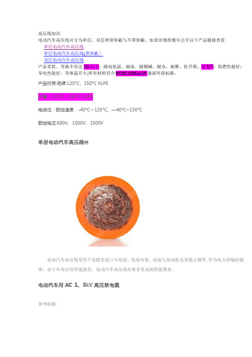
高压线知识电动汽车高压线可分为单层、双层和带屏蔽与不带屏蔽,如需详细参数可点开以下产品链接查看单层电动汽车高压线单层电动汽车高压线(带屏蔽)双层电动汽车高压线产品柔软、弯曲半径达5D以下;耐高低温、耐油、耐酸碱、耐水、耐磨、抗开裂、抗UV;阻燃性能好;导电性能好,导体温升小;所有材料符合ROHS&REACH最新环保标准。
产品材质:绝缘:125°C、150°C XLPE护套:125°C、150°C XLPE电缆性:额定温度:-40°C~125°C、—40°C~150°C额定电压:600V、1000V、1500V单层电动汽车高压线特电动汽车高压线是用于连接充电口与电池、电池内部、电池与发动机及其他元器件,作为电力传输的载体。
由于车内应用环境恶劣,电动汽车高压线有着非常高的性能要求。
电动汽车用AC 1。
5kV高压软电缆参考标准:1。
单层(Single Layer)双层电动汽车高压线简介电动汽车用AC 1.5kV高压软电缆参考标准:2.双层(Double Layer)带屏蔽电动汽车高压线简介电动汽车用AC 1.5kV高压软电缆参考标准:3。
屏蔽(Shielded)产品材质:绝缘:125°C、150°C XLPE护套:125°C、150°C XLPE电缆特性:额定温度:—40°C~125°C、-40°C~150°C额定电压:600V、1000V、1500V一、前言1。
1本守则规定了客车用线束安装与调试时必须遵守的规则。
1。
2本守则适用于我公司所有客车线束的安装及调试。
二、整车线束的安装1。
线束安装、调试通用要求:1。
1整车线束用扎带绑扎时,间距控制在300以内;用钢卡固定时,间距控制在400以内;线束固定可靠,相对扎带及钢卡之间无相对运动;发动机周圈用钢卡固定,扎带进行辅助绑扎。
罗赫高压电源驱动器BM61M41RFV-C评估板说明书
During Use
[5] Be careful to not allow conductive objects to come into contact with the board. [6] Brief accidental contact or even bringing your hand close to the board may result in
Bill of Materials Device
Parts Number
Gate Driver
U1
C11 Input Capacitor
C14
Input signal filter
R12, R13 C12, C13
C21 Output Capacitor
C22
R21
Gate
R22
Test pin Spacer
2/7
2019.10
BM61M41RFV-EVK001
User’s Guide
Schematics R12, R13, R21 and R22 are implemented interim resisters for shipment check.பைடு நூலகம்Please replace each resister which can work with Power Device or input device appropriately.
depending on the circumstances, explosion or other permanent damages. [8] Be sure to wear insulated gloves when handling is required during operation.
光伏电缆太阳能专用电缆

光伏电缆时常暴露在阳光之下,光伏电缆太阳能系统常常会在恶劣环境条件下使用,光伏电缆如高温和紫外线辐射.在欧洲,晴天时将导致太阳能系统的现场温度高达100°C.目前,我们可采用的各种材料有PVC、橡胶、TPE和高品质交叉连结材料,但遗憾的是,额定温度为90°C的橡胶电缆,还有即便是额定温度为70°C的PVC电缆也常常在户外使用光伏电缆,目前国家金太阳工程频频上马,有许多承建商为了节省成本,不选择太阳能系统专用电缆,而是选择普通的pvc电缆来替代光伏电缆,显然,这将大大影响系统的使用寿命.光伏电缆的特性是由其电缆专用绝缘料和护套料决定的,我们称之为交联PE,经过辐照加速器辐照以后,光伏电缆料的分子结构会发生改变,从而提供其个方面的性能。
电站中常见的光伏电缆及材料的用途和使用环境做详细的介绍。
电缆按照光伏电站的系统可分为直流电缆及交流电缆,根据用途及使用环境的不同分类如下:1.光伏电缆直流电缆(1)组件与组件之间的串联电缆。
(2)组串之间及其组串至直流配电箱(汇流箱)之间的并联电缆。
亚太线缆--致力于贯通全亚洲(3)直流配电箱至逆变器之间电缆。
以上电缆均为直流电缆,户外敷设较多,需防潮、防暴晒、耐寒、耐热、抗紫外线,某些特殊的环境下还需防酸碱等化学物质。
2.光伏电缆交流电缆(1)逆变器至升压变压器的连接电缆。
(2)升压变压器至配电装置的连接电缆。
(3)配电装置至电网或用户的连接电缆。
此部分光伏电缆为交流负荷电缆,户内环境敷设较多,可按照一般电力电缆选型要求选择。
3.光伏专用电缆光伏电缆光伏电站中大量的直流电缆需户外敷设,环境条件恶劣,其电缆材料应根据抗紫外线、臭氧、剧烈温度变化和化学侵蚀情况而定。
普通材质电缆在该种环境下长期使用,将导致电缆护套易碎,甚至会分解电缆绝缘层。
这些情况会直接损坏电缆系统,同时也会增大电缆短路的风险,从中长期看,发生火灾或人员伤害的可能性也更高,大大影响系统的使用寿命。
基于混沌时域反射技术的电力电缆绝缘缺陷检测方法

基于混沌时域反射技术的电力电缆绝缘缺陷检测方法
范亚洲
【期刊名称】《机械与电子》
【年(卷),期】2024(42)3
【摘要】为提高电力电缆绝缘缺陷检测的精度,提出一种基于混沌时域反射技术的电力电缆绝缘缺陷检测方法。
采用变分模态分解方法将噪声信号在不同的模态分量中分解,通过自适应小波包分解将电力电缆信号分解在高低频分量中,使用阈值法将不含有局部信号的分量过滤处理,完成信号去噪处理。
信号经过去噪处理后,通过混沌时域反射技术将电力电缆信号划分为参考信号和探测信号,根据信号和电力电缆绝缘位置故障点的反射信号完成采样处理,在相关峰的时间延迟以及幅值信息中获取缺陷发生的位置,判断故障类型,进而实现电力电缆绝缘缺陷检测。
经实验测试结果表明,所提方法可以全面提升检测结果的准确性。
【总页数】5页(P50-53)
【作者】范亚洲
【作者单位】广东电网有限责任公司电力科学研究院
【正文语种】中文
【中图分类】TM855
【相关文献】
1.基于交流耐压试验的电力电缆绝缘缺陷检测方法研究
2.解读电力电缆绝缘缺陷检测方法的研究
3.基于时域反射技术的电缆渗水缺陷检测方法
4.基于时域反射技术的电力电缆局部缺陷检测方法
因版权原因,仅展示原文概要,查看原文内容请购买。
高压电力电缆编号标准
高压电力电缆编号高压电力电缆编号名称用途使用特性执行标准227IEC01 BV 单芯硬导体无护套电缆固定布线用在正常使用时,导体最高温度为70℃GB/T5023-97227IEC02 RV 单芯软导体无护套电缆固定布线用同上227IEC05 BV 导体温度为70℃的单芯实心导体无护套电缆内部布线用同上227IEC06 RV 导体温度为70℃的单芯软导体无护套电缆内部布线用同上227IEC07 BV-90 导体温度为90℃的单芯实心导体无护套电缆内部布线用在正常使用时,导体最高温度为90℃高压电力电缆编号:227IEC08 RV-90 导体温度为90℃的单芯软导体无护套电缆内部布线用227IEC10 BVV 轻型聚氯乙烯护套电缆固定布线用在正常使用时,导体最高温度为70℃227IEC42 RVB 扁型无护套软线固定布线用同上227IEC52 RVV 轻型聚氯乙烯护套软线固定布线用同上227IEC53 RVV 普通聚氯乙烯护套软线固定布线用同上BV 铜芯聚氯乙烯绝缘电缆固定布线1.额定电压为450/750V和300/500V。
2.电缆的长期允许工作温度应不超过70℃。
3.电缆的敷设温度应不低于0℃。
4.外径小于25mm电缆的允许弯曲半径应不小于4D,外径为25mm及以上电缆的允许弯曲半径应不小于6D。
高压电力电缆编号:D为电缆外径JB8734-1998BLV 铝芯聚氯乙烯绝缘电缆固定布线BVR 铜芯聚氯乙烯绝缘软电缆固定布线时要求柔软的场合BVV 铜芯聚氯乙烯绝缘聚氯乙烯护套圆型电缆固定布线BLVV 铝芯聚氯乙烯绝缘聚氯乙烯护套圆型电缆固定布线BVVB 铜芯聚氯乙烯绝缘聚氯乙烯护套扁型电缆固定布线BLVVB 铝芯聚氯乙烯绝缘聚氯乙烯护套扁型电缆固定布线110KV及以上交联聚乙烯绝缘电力电缆高压电力电缆编号阻燃电缆和耐火电缆的结构、特性及选用陶晶(国家电力公司西北勘测设计研究院,西安710065)关键词:阻燃电缆;低卤低烟阻燃电缆;无卤低烟阻燃电缆;耐火电缆;矿物绝缘电缆摘要:介绍了阻燃电缆和耐火电缆的概念、特性、结构及分类,并针对不同类别电缆的具体特性结合现场供电要求提出了上述电缆在设计选用、订货及敷设施工中应注意的几个问题。
高压电缆设备终端的分类及其选型原则解析

插入式电缆终端的安装步骤基本上与第1类相同,如用于GIS组合电器,环氧树脂套管可提前在工厂安装到GIS的电缆进线仓上,环氧树脂套管能够完全将电缆进线仓内的SF6气体与外部隔离,减少了厂家现场配合工作量。但当电缆在试验中发生问题需要进行处理时,仍然需要对电缆进线仓内的气体进行充放处理。另外插入式电缆终端如用在变压器时,其安装、试验与第1类常规型电缆终端的工作量相同。图3为插入到GIS组合电器的插入式电缆终端。
!
"环氧树脂套管可提前安装到GIS或变压器上并进行连接,可与GIS或变压器同时进行试验;#"只需在现场完成好电缆头部分的装配;$"可单独用试验套管对电缆进行试验,无须设备厂家配合;%"试验合
格后将电缆插入环氧树脂套管,在安装好接地线后就完成了全部的安装工作。图4为典型插拔式终端结构示意图。
- 1、下载文档前请自行甄别文档内容的完整性,平台不提供额外的编辑、内容补充、找答案等附加服务。
- 2、"仅部分预览"的文档,不可在线预览部分如存在完整性等问题,可反馈申请退款(可完整预览的文档不适用该条件!)。
- 3、如文档侵犯您的权益,请联系客服反馈,我们会尽快为您处理(人工客服工作时间:9:00-18:30)。
No.YES NO N/A 1
2
4
5
67
89
1011
12 Remark 备注
Name
Sign Tag Description MCR-E-01A
ELECTRICAL __CI_IMAGE__
COSLPIONEER PROJECT 188
__LOGO_IMAGE__HIGH VOLTAGE CABLE 高压电缆
Tag No
System Description Sub-System No
Sub-System Description System No
Cable type : 电缆型号 Manufacture :厂商 Check cable have been glanded in accordance with the cable manufacturers instructions and in Check cable size, type and routing with latest revision of cable schedule and relevant electrical drawings 按照最新的电缆手册及相关的电气图纸检查电缆尺寸,型号以及路径3
particular check that any stress relief measures have been incorporated 确认电缆填料函的安装符合电缆厂家的说明,尤其注意检查是否采取了应力消除措施 L1, L2 - L3 MegOhms
Check earth connections for tightness 检查接地连接是否紧固 Check that cable gland plates for single core cables are manufactured from non ferrous material 检查单芯电缆的填料函都是由不含铁金属的物质制造的 Drawings Reference Check cable gland certificates meet with area classification 检查电缆填料函证书能够满足其所在的区域等级要求 Mechanical completion Check Items 安装报验需确认以下项目 Location
Cable No.电缆号
HV pressure test 高压耐压试验
YRS
COSL Third Party
L1, L2 - L3 MegOhms
Pressure Test Instrument Type 耐压测试仪表型号- Serial No.序列号3 RD Discharge all cores to earth 第三次接地放电Reconnection check 重接检查
IR Test Instrument Type 绝缘测试仪表型号- Serial No.序列号 L1 - L2, L3 MegOhms L1, L2 - L3 Leakage mA
L1, L2, L3 - E MegOhms 2 ND Discharge all cores to earth 第二次接地放电 Test Voltage 测试电压-2 ND IR test 第二次绝缘测试
Pressure Test 耐压测试 Tests Voltage -测试电压 Test duration 持续时间 - L1, L2, L3 - E Leakage mA L1 - L2, L3 Leakage mA Cable Information 电缆信息
Note:Above check points must be finished before hereinafter commencing 注意:在开始下面的检查前,上述的检查项目必须完成1st IR test 第一次绝缘测试 Test Voltage 测试电压 -Discharge all cores to earth 将所有的电缆线芯接地放电 To :终至 Size :尺寸
Grade : 级别
From :起始
L1, L2, L3 - E MegOhms L1 - L2, L3 MegOhms。
