W4F601-RC-10中文资料
西门子SINAMICS V10

当两个不同尺寸变频器并排安装,间距需要选择其中侧面间距的较大值
Date
Author
Page 18
SIEMENS 2008/ Internal Use Only IA&DT / SD / PMt
连接端子
输入输出 端子
s
中文标签
数字量 数字量
输出
输入
模拟量 输入/输出
强电
标识符号 电源端子 电机端子
采用的标准插接端子 接线非常方便
C05-C08 内置连接模式
DI 1
0-10 V
AI 速度给定
DI 2
DI 1 -ON/OFF
DI 2 –本地/远程
M
s
DI 1 DI 2 DI 2
DI1 – ON/OFF
M
DI2 – 频率 1 DI3 – 频率 2
AI
PLC DI 1 DI 2 NPN
M
Date
DI 1 – ON+正转 DI 2 – ON+反转
额定输入电压: 3AC 380V
Date
9 10 11 12
13 14 15 16
C E 1 5 - 5UA0
版本 标准
1 1 2 2 2 2 2 2 2 3 3 3 3
Author
5–5 7–5 1–1 1–5 2–2 3–0 4–0 5–5 7–5 1–1 1–5 1–8 2–2
0.55 kW 0.75 kW 1.1 kW 1.5 kW 2.2 kW 3.0 kW 4.0 kW 5.5 kW 7.5 kW 11 kW 15 kW 18.5 kW 22 kW
Page 8
无滤波器
FS A
FS B
FS C
FLUXUS F601技术规格说明书

Features•Transmitterconfigurable for flow and thermal energy mea-surement–Flow measurement for all acoustically penetrable fluids–Integrated thermal energy measurement for a typical heat and refrigerating agents–Temperature range -40 to+392 °F, with WaveInjector max.+752 °F•Precise bidirectional and highly dynamic flow measurementwith the non-invasive clamp-on technology•Calibrated transducers and transmitters with traceable certif-icates•Automatic loading of calibration data and transducer detec-tion for a fast and easy set-up (less than 5 min), providing precise and long-term stable results•High precision at fast and slow flow rates, high temperature and zero point stability•Portable, easy-to-use flow transmitter with 2 flow channels, multiple inputs/outputs, an integrated data logger with a seri-al interface•Integrated wall thickness measurement with connectable wall thickness probe•The transmitter is water and dust-tight (NEMA 4), resistant against oil, many liquids and dirt•Robust, water-tight (NEMA 4) transport case with compre-hensive accessories•Li-Ion battery provides up to 25 hours of measurement oper-ation•User-friendly design•QuickFix for a simple and fast transmitter fixation, e.g., on pipesApplicationsDesigned for harsh environments and applicable in all areas such as drinking water and sewerage industry, power plants, producing industry, food industry and many moreExample applications:•Operation measurements•Data gathering in energy management and certifications ac-cording to ISO 50001•Survey of pump performances•Hydraulic balancing•Verification of installed measuring systems•Supervision of permanently installed meters, service and maintenance FLUXUS F601Measurement with transducers mounted with mounting frames and flow transmitter fixed to the pipe with the QuickFix pipe mounting fixture Measurement equipment in transport casePortable ultrasonic flow measurement of liquidsPortable instrument for non-invasive, quick flow and energy measurement with clamp-on technology for all types of pipingTSFLUXUS_F601V2-4-1US_Lus, 2020-02-01FLUXUS F601Technical specification2020-02-01, TSFLUXUS_F601V2-4-1US_Lus2Function . . . . . . . . . . . . . . . . . . . . . . . . . . . . . . . . . . . . . . . . . . . . . . . . . . . . . . . . . . . . . . . . . . . . . . . . . . . . . . . . . . . . . . .3Measurement principle. . . . . . . . . . . . . . . . . . . . . . . . . . . . . . . . . . . . . . . . . . . . . . . . . . . . . . . . . . . . . . . . . . . . . . . . . . . . .3Calculation of volumetric flow rate . . . . . . . . . . . . . . . . . . . . . . . . . . . . . . . . . . . . . . . . . . . . . . . . . . . . . . . . . . . . . . . . . . . .3Number of sound paths . . . . . . . . . . . . . . . . . . . . . . . . . . . . . . . . . . . . . . . . . . . . . . . . . . . . . . . . . . . . . . . . . . . . . . . . . . . .4Typical measurement setup. . . . . . . . . . . . . . . . . . . . . . . . . . . . . . . . . . . . . . . . . . . . . . . . . . . . . . . . . . . . . . . . . . . . . . . . .5Transmitter . . . . . . . . . . . . . . . . . . . . . . . . . . . . . . . . . . . . . . . . . . . . . . . . . . . . . . . . . . . . . . . . . . . . . . . . . . . . . . . . . . . . .6Technical data . . . . . . . . . . . . . . . . . . . . . . . . . . . . . . . . . . . . . . . . . . . . . . . . . . . . . . . . . . . . . . . . . . . . . . . . . . . . . . . . . . .6Dimensions. . . . . . . . . . . . . . . . . . . . . . . . . . . . . . . . . . . . . . . . . . . . . . . . . . . . . . . . . . . . . . . . . . . . . . . . . . . . . . . . . . . . . .7Standard scope of supply. . . . . . . . . . . . . . . . . . . . . . . . . . . . . . . . . . . . . . . . . . . . . . . . . . . . . . . . . . . . . . . . . . . . . . . . . . .8Adapters. . . . . . . . . . . . . . . . . . . . . . . . . . . . . . . . . . . . . . . . . . . . . . . . . . . . . . . . . . . . . . . . . . . . . . . . . . . . . . . . . . . . . . . .8Example for the equipment of a transport case . . . . . . . . . . . . . . . . . . . . . . . . . . . . . . . . . . . . . . . . . . . . . . . . . . . . . . . . . .9Transducers . . . . . . . . . . . . . . . . . . . . . . . . . . . . . . . . . . . . . . . . . . . . . . . . . . . . . . . . . . . . . . . . . . . . . . . . . . . . . . . . . . .10Transducer selection . . . . . . . . . . . . . . . . . . . . . . . . . . . . . . . . . . . . . . . . . . . . . . . . . . . . . . . . . . . . . . . . . . . . . . . . . . . . .10Transducer order code. . . . . . . . . . . . . . . . . . . . . . . . . . . . . . . . . . . . . . . . . . . . . . . . . . . . . . . . . . . . . . . . . . . . . . . . . . . .11Technical data . . . . . . . . . . . . . . . . . . . . . . . . . . . . . . . . . . . . . . . . . . . . . . . . . . . . . . . . . . . . . . . . . . . . . . . . . . . . . . . . . .12Transducer mounting fixture . . . . . . . . . . . . . . . . . . . . . . . . . . . . . . . . . . . . . . . . . . . . . . . . . . . . . . . . . . . . . . . . . . . . . .14Coupling materials for transducers . . . . . . . . . . . . . . . . . . . . . . . . . . . . . . . . . . . . . . . . . . . . . . . . . . . . . . . . . . . . . . . .17Connection systems . . . . . . . . . . . . . . . . . . . . . . . . . . . . . . . . . . . . . . . . . . . . . . . . . . . . . . . . . . . . . . . . . . . . . . . . . . . .18Clamp-on temperature probe (optional). . . . . . . . . . . . . . . . . . . . . . . . . . . . . . . . . . . . . . . . . . . . . . . . . . . . . . . . . . . . .19Technical data . . . . . . . . . . . . . . . . . . . . . . . . . . . . . . . . . . . . . . . . . . . . . . . . . . . . . . . . . . . . . . . . . . . . . . . . . . . . . . . . . .19Fixation. . . . . . . . . . . . . . . . . . . . . . . . . . . . . . . . . . . . . . . . . . . . . . . . . . . . . . . . . . . . . . . . . . . . . . . . . . . . . . . . . . . . . . . .20Wall thickness measurement (optional). . . . . . . . . . . . . . . . . . . . . . . . . . . . . . . . . . . . . . . . . . . . . . . . . . . . . . . . . . . . .21Technical data . . . . . . . . . . . . . . . . . . . . . . . . . . . . . . . . . . . . . . . . . . . . . . . . . . . . . . . . . . . . . . . . . . . . . . . . . . . . . . . . . .21Technical specification FLUXUS F6013TSFLUXUS_F601V2-4-1US_Lus, 2020-02-01FunctionMeasurement principleThe transducers are mounted on the pipe which is completely filled with the fluid. The ultrasonic signals are emitted alter-nately by a transducer and received by the other. The physical quantities are determined from the transit times of the ultra-sonic signals.Transit time difference principleAs the fluid where the ultrasound propagates is flowing, the transit time of the ultrasonic signal in flow direction is shorter than the one against the flow direction.The transit time difference Δt is measured and allows the flowmeter to determine the average flow velocity along the prop-agation path of the ultrasonic signals. A flow profile correction is then performed in order to obtain the area averaged flow velocity, which is proportional to the volumetric flow rate.The integrated microprocessors control the entire measuring cycle. The received ultrasonic signals are checked for mea-surement usability and evaluated for their reliability. Noise signals are eliminated.HybridTrekIf the gaseous or solid content in the fluid increases occasionally during measurement, a measurement with the transit time difference principle may no longer be possible. NoiseTrek mode will then be selected by the flowmeter. This mea-surement method allows the flowmeter to achieve a stable measurement even with high gaseous or solid content.The transmitter can switch automatically between transit time and NoiseTrek mode without any changes to the measure-ment setup.Calculation of volumetric flow rate= k Re · A · k a · where-volumetric flow ratek Re -fluid mechanics calibration factor A -cross-sectional pipe area k a -acoustical calibration factor Δt -transit time differencet γ-average of transit times in the fluidV ꞏ∆t2tγ⋅-----------VꞏFLUXUS F601Technical specification2020-02-01, TSFLUXUS_F601V2-4-1US_Lus4Number of sound pathsThe number of sound paths is the number of transits of the ultrasonic signal through the fluid in the pipe. Depending on the number of sound paths, the following methods of installation exist:•reflect arrangementThe number of sound paths is even. The transducers are mounted on the same side of the pipe. Correct positioning of the transducers is easier.•diagonal arrangementThe number of sound paths is odd. The transducers are mounted on opposite sides of the pipe.•direct modeDiagonal arrangement with 1 sound path. This should be used in the case of a high signal attenuation by the fluid, pipe or coatings.The preferred method of installation depends on the application. While increasing the number of sound paths increases the accuracy of the measurement, signal attenuation increases as well. The optimum number of sound paths for the pa-rameters of the application will be determined automatically by the transmitter.As the transducers can be mounted with the transducer mounting fixture in reflect arrangement or diagonal arrangement,the number of sound paths can be adjusted optimally for the application.Technical specification FLUXUS F6015TSFLUXUS_F601V2-4-1US_Lus, 2020-02-01Typical measurement setupFLUXUS F601Technical specification2020-02-01, TSFLUXUS_F601V2-4-1US_Lus6TransmitterTechnical dataFLUXUS F601design portable measurement measurement principle transit time difference correlation principle,automatic NoiseTrek selection for measurements with high gaseous or solid content flow velocity ft/s 0.03 to 82repeatability 0.15 % of reading ±0.02 ft/s fluid all acoustically conductive liquids with <10% gaseous or solid content in volume (transit time difference principle)temperature com-pensationcorresponding to the recommendations in ANSI/ASME MFC-5.1-2011measurement uncertainty (volumetric flow rate)measurement uncer-tainty of measuring system 1±0.3 % of reading ±0.02 ft/sincludes calibration certificate traceable to NIST calibration facility ISO 17025 accreditedmeasurement uncer-tainty at the measu-ring point 2±1 % of reading ±0.02 ft/s transmitter power supply •100 to 230 V/50 to 60 Hz (power supply unit: IP40, 32 to 104 °F)•10.5 to 15 V DC (socket at transmitter)•integrated batteryintegrated battery Li-Ion, 7.2 V/6.2 Ah •operating time h •> 14 (without outputs, inputs and backlight)•> 25 (1 measuring channel, ambient temperature > 50 °F, without outputs, inputs and backlight)power consumption W < 6 (with outputs, inputs and backlight), charging: 18number of measuring channels 2damping s 0 to 100 (adjustable)measuring cycle Hz 100 to 1000 (1 channel)response time s 1 (1 channel), option: 0.07housing material PA, TPE, AutoTex, stainless steel degree of protection NEMA 4dimensions in see dimensional drawing weight lb 4.6fixation QuickFix pipe mounting fixture ambient temperature °F 14 to 140display 2 x 16 characters, dot matrix, backlight menu language English, German, French, Dutch, Spanish measuring functions physical quantities volumetric flow rate, mass flow rate, flow velocity, thermal energy rate (if temperature inputs are installed)totalizer volume, mass, optional: thermal energy calculation functions average, difference, sum diagnostic functions sound speed, signal amplitude, SNR, SCNR, standard deviation of amplitudes and transit times communication interfaces service interfaces •RS232•USB (with adapter)process interfaces •Modbus RTU (optional)accessories serial data kit •сable RS232•adapter RS232 - USB software •FluxDiagReader: download of measured values and parameters, graphical presentation•FluxDiag (optional): download of measurement data, graphical presentation, report generationadapter AO5, AO6, AO7, AO8, AI1, AI2transport case dimensions: 19.7 x 15.7 x 7.5 in data logger loggable values all physical quantities, totalized values and diagnostic values capacity > 100000 measured values1with aperture calibration of the transducers2for transit time difference principle and reference conditionsTechnical specificationFLUXUS F6017TSFLUXUS_F601V2-4-1US_Lus, 2020-02-01DimensionsoutputsThe outputs are galvanically isolated from the transmitter.number see standard scope of supply, max. on request •switchable current outputThe switchable current outputs are menu selectable all together as passive or active.range mA 4 to 20 (3.2 to 24)accuracy 0.04 % of reading ±3 μA active output U int = 24 V, R ext < 500 Ωpassive output U ext = 8 to 30 V, depending on R ext (R ext < 900 Ω at 30 V)•frequency output range kHz 0 to 5open collector 24 V/4 mA •binary output optorelay 26 V/100 mA binary output as alarm output •functions limit, change of flow direction or error binary output as pulse output •functions mainly for totalizing •pulse value units 0.01 to 1000•pulse width ms 1 to 1000inputsThe inputs are galvanically isolated from the transmitter.number see standard scope of supply, max. 4•temperature input type Pt100/Pt1000connection 4-wire range °F -238 to +1040resolution K 0.01accuracy ±0.01 % of reading ±0.03 K •current input accuracy 0.1 % of reading ±10 μA passive input R int = 50 Ω, P int < 0.3 W •range mA -20 to +20•voltage input range V 0 to 1accuracy 0.1 % of reading ±1 mV internal resistance R int = 1 MΩFLUXUS F6011with aperture calibration of the transducers2for transit time difference principle and reference conditionsFLUXUS F601Technical specification2020-02-01, TSFLUXUS_F601V2-4-1US_Lus8Standard scope of supplyAdaptersF601 BasicF601 Energyapplicationflow measurement of liquids2 independent measuring channels,2 calculation channelswall thickness measurement (wall thickness probe to be ordered separately)integrated thermal energy computersimultaneous monitoring of 2 energy flowstemperature-compensated calculation of mass flow rate outputsswitchable current output 22binary output 22inputstemperature input -4accessories transport casex x power supply unit, mains cable x xbattery x xadapterAO6AO6, AI1, AI2QuickFix pipe mounting fixture for transmitter x x serial data kit x x measuring tape x x user manual,Quick start guidexxTechnical specification FLUXUS F6019TSFLUXUS_F601V2-4-1US_Lus, 2020-02-01Example for the equipment of a transport caseF601softwarepower supply unit,mains cabletransducer mounting fixturemeasuring tapetransmittertransducersuser manual,Quick start guidecoupling compoundwall thickness probe (optional)QuickFix pipe mounting fixturetemperature probes (optional)serial data kitFLUXUS F601Technical specification2020-02-01, TSFLUXUS_F601V2-4-1US_Lus10TransducersTransducer selectiontransducer order code FSG 15.719.7157.5255.9FSK 3.97.978.7255.9FSM 2 3.939.4133.9FSP 0.98215.723.6FSQ 0.390.985.915.7FSS0.240.39 2.80.20.4242040200inner pipe diameter [in]transducer order code FSG 0.43FSK 0.2FSM 0.1FSP 0.05FSQ 0.02FSS0.010.20.40.60.811.2pipe wall thickness [in]recommendedpossibleTransducer order code1, 2345, 67, 89 to 11no. of charactert r a n s d u c e rt r a n s d u c e r f r e q u e n c y-a m b i e n t t e m p e r a t u r ee x p l o s i o n p r o t e c t i o nc o n n e c t i o n s y s t e m-e x t e n s i o n c a b l e/o p t i o nd e s c r i p t i o nFSset of ultrasonic flow transducers for liquids measurement, shear wave G 0.2 MHz K 0.5 MHz M 1 MHz P 2 MHz Q 4 MHz S8 MHzN normal temperature range Eextended temperature range NNnot explosion proof NLwith Lemo connectorXXX0 m: without extension cable > 0 m: with extension cable LC long transducer cableTechnical dataShear wave transducers (nonEx, NL)Shear wave transducers (nonEx, NL, extended temperature range)Transducer mounting fixtureOrder code1, 234567 to 9no. of charactert r a n s d u c e r m o u n t i n g f i x t u r et r a n s d u c e r-m e a s u r e m e n t a r r a n g e -m e n ts i z e-f i x a t i o no u t e r p i p e d i a m e t e rd e s c r i p t i o nFS mounting framesLM ladder chain mounting accessory VP portable Variofix TB tension beltsWLtransducer box for WaveInjector A all transducersK transducers with transducer frequency G, K M transducers with transducer frequency M, P Q transducers with transducer frequency Q Stransducers with transducer frequency SD reflect arrangement or diagonal arrangement/direct mode Rreflect arrangement S small Mmedium C chainsNwithout fixation L080.5 to 8 in L220.5 to 22 in 0100.39 to 3.9 in 0250.39 to 9.8 in 0550.39 to 21.7 in 150 2 to 59.1 in 210 2 to 82.7 inCoupling materials for transducersTechnical datanormal temperature range(4th character of transducer order code =N)extended temperature range(4th character of transducer order code =E)WaveInjector WI-400< 212 °F< 338 °F< 302 °F< 392 °F< 536 °F 536 to 752 °Fcoupling compound type Ncoupling compound type Ecoupling compound type Ecoupling compound type E or Hcoupling pad type A and coupling pad type VT coupling pad type B and coupling pad type VTtypeambient temperature °Fcoupling compound type N -22 to +266coupling compound type E -22 to +392coupling compound type H -22 to +482coupling pad type A max. 536coupling pad type B 536 to 752coupling pad type VT14 to +392coupling pad not to be used for transducer mounting fixture with magnetsConnection systemsCableCable lengthtransducer cable type 1699weightlb/ft 0.06ambient temperature °F -67 to +392cable jacket materialPTFE outer diameter in 0.11thickness in0.01color brown shield xsheath materialstainless steel 304outer diameter in0.31extension cable type17502551standard lengthft1632-max. length ft 32see table below weight lb/ft 0.080.06ambient temperature °F < 144-13 to +176cable jacket material PE TPE-O outer diameter in 0.240.31thickness in 0.02color black black shield x x sheath material stainless steel 304-outer diameter in 0.35-remark optionaltransducer frequencyF, G, H, K M, P Q Sconnection system NL transducers technical type x y l x y l x y l x y l *D***Z71ft 69≤ 8266≤ 8263≤ 8233≤ 65option LC:*L***Z71ft 622≤ 82226≤ 82263≤ 82---1 l > 82 to 328 ft on requestx, y = transducer cable length l = max. length of extension cableClamp-on temperature probe (optional) Technical dataFixationTechnical specification FLUXUS F60121TSFLUXUS_F601V2-4-1US_Lus, 2020-02-01Wall thickness measurement (optional)The pipe wall thickness is an important pipe parameter which has to be determined exactly for a good measurement. How-ever, the pipe wall thickness often is unknown.The wall thickness probe can be connected to the transmitter instead of the flow transducers and the wall thickness mea-surement mode is activated automatically.Acoustic coupling compound is applied to the wall thickness probe which then is placed firmly on the pipe. The wall thick-ness is displayed and can be stored directly in the transmitter.Technical dataCableDWR1NZ7order codeACC-PO-G601-/W6measuring range 1in 0.04 to 9.8resolution in 0.0004accuracy1 % ±0.004 in fluid temperature °F-4 to +392,short-time peak max. 932сable type 2616lengthft41The measuring range depends on the attenuation of the ultrasonic signal in the pipe. For strongly attenuating plastics (e.g., PFA, PTFE, PP) the measuring range is smaller.2616ambient temperature °F <392cable jacket materialFEP outer diameter in 0.2color black shield xFLEXIM AMERICAS CorporationEdgewood, NY 11717USATel.:(631) 492-2300Fax:(631) 492-2117internet: e-mail:*****************1-888-852-7473Subject to change without notification.Errors excepted. FLUXUS is a registered trademark of FLEXIM GmbH.Copyright (©) FLEXIM GmbH 2020 2020-02-01, TSFLUXUS_F601V2-4-1US_Lus。
RC系列变频器说明书-中文版[1]
![RC系列变频器说明书-中文版[1]](https://img.taocdn.com/s3/m/397e121514791711cc79176a.png)
前言...................................................................................................................................................... 1
第六章 參數說明........................................................................................................................ 23
6.1 恆壓供水功能說明................................................................................................................. 23 6.2 參數一覽表............................................................................................................................. 24 6.3 一般參數說明......................................................................................................................... 26 6.4 恆壓供水專用參數說明 ........................................................................................................ 29
RC4 中文操作手册范本
手册引导内容提要1介绍1.1手册结构1.2补充文件1.3操作手册使用人群1.4手册中使用的信号和警示1.5使用的方式和缩写1.6版本附件2设备描述2.1目的2.2潜在的危险3总述3.1电源3.2外加24VDC3.3使用的电缆型号3.4安全须知3.4.1Congrav RC-4使用安全须知3.4.2安装安全须知3.4.3接线安全须知3.4.4使用和操作安全须知4硬件描述4.1Congrav RC-4:类型4.2Congrav RC-4A:显示和按键4.2.1集成按键及其功能4.2.2显示和功能组成4.3参数更改4.3.1数字输入4.3.2固定参数设置的选择4.3.3如果….,更改参数不被接受4.4Congrav RC-4B:4.5Congrav RC-4的插卡槽4.5.1现场的可能连线4.6Congrav RC-4的基本功能4.6.1插入卡RC4-MSIO4.6.1.1XS1.1:与主计算机的连接4.6.1.2XS1.2:与ISC现场总线的连接4.6.1.3XS1.3:与调试解调器和工控电脑的连接4.7Congrav RC-4的选项卡4.7.1CDIO插入卡4.7.2DIOP插入卡4.7.2.1输入输出模式-数字式RC-4的终端功能4.7.3ANOP插入卡4.7.3.1输入输出模式-模拟式RC-4的终端功能4.7.4Profibus模式5调试5.1安装5.2调试,Congrav RC-4的开机5.3Congrav RC-4:软件升级5.4ISC-CM:软件升级6菜单页F100安装结构6.1F110:安装模式6.2模拟结构6.3F120:主计算机操作6.4F130:显示内容改变6.5连锁停机6.6时间和日期6.7F150:配方处理6.7.1设定值斜线,设定值阈值6.7.2调试操作7F200:打印机结构,内存值重设7.1打印功能7.2F210:如何清除记忆内容8F300:设定值输入和选择8.1安装设定值8.2加料器设定值8.2.1`设定值的模拟控制8.2.2设定值斜线,设定值阈值(菜单页F150)8.3选项8.4F310:滞后时间8.5报警停机9F400:安装的实际值,总产量重设9.1F430:总产量重设10单台加料器操作10.1加料器页的抬头10.2Kxx0:加料器控制10.3操作功能10.3.1开机 5410.3.2停机 5410.3.3报警重设10.3.4补料 5510.3.5删除 5510.3.6开始试样10.3.7开始去皮10.3.8右侧行实际值的显示10.4Kxx1:产品参数10.4.1自动去皮10.4.2检查最大输出10.4.3堆积密度10.4.4体积最大输出10.4.5十进制转换10.4.5.1十进制转换的设置10.4.6模式 5910.4.6.1失重式加料(GF)10.4.6.2体积式控制(VR)10.4.6.3体积式设置(VS)10.4.6.4排料(DI)10.4.6.5检查最大输出(CM)10.4.6.6重量式排料(GD)10.4.6.7体积式加料(VF)10.4.6.8测量(M)10.4.6.9运行过程中GF和VF模式转换10.5Kxx2:控制参数10.5.1PID控制的设置10.5.1.1控制成套配合10.5.1.2重量式计算最大输出10.5.1.2.1CM值的存储11F500:报警报告和开机条件11.1报警报告11.2缺省的开机条件11.3系列驱动控制操作的错误代码11.3.1系列变频器11.3.2振动放大器控制器ISC-VC11.4Kxx5:报警结构12硬件结构12.1 Kxx8:ISC-CM(-A)的硬件结构12.1.1 速度输入12.1.2 传感器(重量读取)的结构12.1.3 驱动控制器12.1.4 ISC-CM-A模拟输入输出的结构12.1.4.1 ISC-CM-A上单台控制的选项12.1.4.2 Kxx8:模拟输入12.1.4.3 Kxx8:模拟输出12.2 ANOP模拟输入输出的结构12.2.1 安装控制和安装的实际值12.2.1.1 菜单页F190的参数12.2.2 ANOP的组分功能12.2.2.1 模拟输入:模拟单台控制12.2.2.2 模拟输出:总操纵量或实际值12.2.2.2.1 模拟输出信号范围的定义12.3 CDIO的数字输入输出12.4 DIOP的数字输入输出12.4.1 DIOP:功能描述12.5 ISC现场总线机构12.5.1 如果构建总线通讯12.5.2 总线通讯的关闭12.6 调试解调器的机构12.7 主计算机操作机构12.7.1 MISO卡上的主计算机接口12.7.2 Profibus DP操作结构12.7.3 以太网接口的结构13校正程序13.1加料器参数13.2加料器参数功能解释13.2.1CP02-加料范围13.2.2CP04-欠载13.2.3CP03-最大输出量13.2.4CP05-过载13.2.5CP06-粗去皮13.2.6CP07-平均重量取数13.2.7CP08-总产量累计分值13.2.8CP09-最小速度13.2.9CP010-最大速度13.2.10CP11-控制偏差13.2.11CP12-报警停机滞后时间13.2.12CP13-联锁类型13.2.13CP14-实际值指示13.2.14CP15-杠杆臂值13.2.15CP16-料斗内容13.2.16CP17-最小补料料位13.2.17CP18-最大补料料位13.2.18CP19-Window/K1/滤波IDL/F, AED 13.2.19CP20-数字速度13.2.19.1标准速度监控13.2.19.2FlexWall-Plus加料器的运动监控13.2.19.3数字式速度取数13.2.19.4推荐输入13.2.20CP21-最大补料时间13.2.21CP22-补料优化13.2.22CP23-稳定时间13.2.23CP24-测样时间13.2.24CP25-防振(AV)切断时间13.2.25CP26-PID控制器接近时间13.2.26CP27-控制器自动化13.2.26.1控制器自动化13.2.26.2开机自动化13.2.26.2.1重复的开机自动化13.2.26.2.2总体开机自动化13.2.27CP28-滤波限制13.2.28CP29-实际值的接纳13.2.29CP30-总操纵量的接纳13.2.30CP31-体积控制(VR)实际值的接纳13.2.31CP32-开机滞后时间13.2.32CP33-称重桥(LWB)的长度13.2.33CP34-重量测试值(WTV)13.2.34CP35-摄取(AP)13.2.35CP36-自动去皮范围13.2.36CP37-无负载时间自动去皮13.2.37CP38-有比例的皮带速度13.2.38CP39-皮带长度13.2.39CP40-dead time way13.3附加参数13.3.1AP01-05 校正13.3.2AP11-可用的称重范围13.3.3AP12-drop out13.3.4AP13-速度模式13.3.5AP14-滑动影响13.3.6AP15-滑动值13.3.7AP16-速度接纳性13.3.8AP17-无负载时间13.3.9AP18-AT时间13.3.10AP19-驱动控制2最小13.3.11AP20-驱动控制2最大14硬件测试功能14.1F140:输入输出测试-外围(安装)14.2Kxx3:输入输出状态显示-外围14.3Kxx4:测试功能和模拟14.3.1模拟模式14.3.2输入输出测试(加料器)15名词解释附件11915.1技术数据15.2电磁兼容性15.3零配件清单15.4可能显示的模式清单15.5菜单页清单插图表图4-1:Congrav RC-4后部视图图4-2:Congrav RC-4后部视图(带ProfiBus模式)1 总介绍1.1手册的结构现有的操作手册包括:RC-4的:●技术操作和●RC-4 HGC软件(其版本请参见封页)按照下列顺序,每章独立描述一个完整的主题:●设备的描述●使用特性●硬件执行●硬件功能定义●操作●软件描述●参数描述和●结构例举1.2附加文件●ISC系统的描述●ISC-CM,ISC-FC和ISC-VC的技术手册●相应主计算机程序手册1.3操作手册所适用的人群操作手册适用于以下两组人群:●经过授权和培训过的专业技术人员来进行安装和其它电气工作。
欧姆龙PLC样本与手册全集

欧姆龙PLC样本与手册全集小型机CP1H选型样本(中文) R05-CN-03CP1H/CP1L 选型样本(中文) SBCA-C-051DCP1L选型样本(英文)P20E-EN-01CP1E 中英文选型样本CP1H操作手册(中文) W450-CN5-02CP1H操作手册(英文) W450-E1-01CP1L操作手册(中文)W462-CN5-03CP1L操作手册(英文)W462-E1-06CP1E 单元软件用户手册(中英文)W480-E1-01 W480-CN5-01 CP1E 单元硬件用户手册(中英文)W479-E1-01 W479-CN5-01 CP1E 单元硬件用户手册(英文)(包含NA)W479-E1-03CP1H/CP1L编程手册(英文) W451-E1-03CP1H/CP1L编程手册(中文)CP1E 指令参考手册(中文)W483-CN5-04CP1E 指令手册(英文)CPM1A-V1 选型样本(英文) P039 E1-11CPM1A 操作手册(英文)W317-E1-4CPM1/1A/2A/2C/SRM1编程手册(英文)W353-E1-1CPM1A 操作手册(中文)OMP-ZCO97101BCPM1A/2A/2AH/2C 编程手册(中文)CPM1操作手册(英文)W262-E1-4CPM2A/2C 选型样本(英文) P049-E1-08CPM2AH 选型样本(中文)CPM2AH-S 选型样本(中文) .P01Z-CN-01CPM2A 操作手册(英文)W352-E1-1CPM2AH-S 操作手册(中文)CPM2A/CPM2AH 操作手册(中文)CPM2C 选型样本(英文)CPM2C 操作手册(英文)W356-E1-08CPM2B 操作手册(中文) OMP-AD000102ACPM2B-S001M-DRT 操作手册(英文) W399-E1-1中型机CJ1系列选型样本(中文)CJ2H/CJ2M选型样本(中文)SBCE-CN-058DC200HX/C200HG/C200HE 选型样本(中文)CJ1M内置I/O操作手册(中文)W395-C1-01CJ1操作手册(中文)W393-C1-02CJ1编程手册(中文)W340-C1-08CJ1最新编程手册(英文)W340-E1-1CJ2 CPU 单元硬件操作手册(中文)W472-CN5-06CJ2操作手册(英文)W472-E1-01CJ2M-MD操作手册(英文)W486-E1-01CJ2编程手册(英文)W473-E1-01CJ1W-AD/DA操作手册(中文)W345-C1-05CJ1W-TC操作手册(中文)W396CJ1W-PTS操作手册(英文)W368-E1-07C200HX/HG/HE 编程手册(中文)OEZ-ZCP97201AC200HE/HG/HX 操作手册(中文)OEZ-ZCI96201AC200H 模拟量(AD001/DA001)操作手册(中文)OMP-ZCO99406A C200H 模拟量I(AD003/DA003)操作手册(英文)W325-E1-04 C200H-TC 温度控制单元操作手册(英文)W124-E1-5C200H 操作手册(英文)W130-E3-5C200HS 安装手册(英文)C200HS 操作手册(英文)CQM1H 选型样本(中文)CQM1H 操作手册(中文)CQM1H 编程手册(中文)CQM1H 系列 CPU 和内装板操作手册(英文)CQM1H 系列 CPU 和内装板编程手册(英文)CQM1H 特殊I/O单元操作手册(中文)CQM1H/CQM1 特殊I/O手册(英文)大型机CS1W-PTS过程控制I/O模块操作手册(英文)W368-E1-07CS1-H选型样本(中文)CS1D选型样本(中文)CS1可编程控制器操作手册(中文) W339-CN5-10CS1编程手册(中文)W340-C1-08CS1最新编程手册(英文)CS1D双机操作手册(英文)W405-E1-06CS1W-AD/DA操作手册(中文)W345-C1-05CS1W-AD/DA最新操作手册(英文)W345-E1-11C500 安装手册(英文)W132-E1-3DC500编程手册(英文)W131-E1-02C500-LK操作手册(英文)W143-E1-05串口通讯C200HW-COM01/02/03/04/05/06 通讯板操作手册(英文)- W304-E1-05通讯命令参考手册(英文)W342-E1-15CS1/CJ1W-SCU/SCB串行通讯单元/板卡操作手册(英文)- W336-E1-10CQM1H-SCB41 操作手册(英文) -W365-E1-02NT-AL001 使用手册(英文)C200H PC-Link 系统手册(英文) -W135-E1-2B以太网CS1-ETN01/11和CJ1-ETN11操作手册(英文)- W343-E1-07CS1/CJ1-ETN21 操作手册(英文)- W420-E1-06CS1/CJ1-ETN21 应用手册(英文)- W421-E1-04CS1D-ETN21D 操作手册(英文)-W430-E1-02CJ1M-CPU1□-ETN 操作手册(英文)- W441-E1-03ControllerLink3G8F7-CLK21/52/12 安装指南(英文) W388-E1-2C200HW/CVM1-CLK21操作手册(中文) -OEZ-ZCO97404ACS/CJ1W/C200HW/CVM1/CQM1H-CLK21 CS1W-RPT01/02/03 操作手册(英文) -W309-E1-113G8F7-CLK12/21/52(-EV1)/13/23/53(-E) 操作手册(英文) -W383-E1-04CS1W/CVM1-CLK12/52/13/53操作手册(英文) -W370-E1-07DeviceNet(Compobus/D)CS1/CJ1-DRM21-V1 操作手册(英文)- W380-E1-07CVM1/C200HW-DRM21/CQM1-DRT21 DRT1系列操作手册(英文)- W267-E1-6 CS1/CJ1系列DRM21操作手册(中文繁体) - SBCD-314H-TW5-01ITNC-EPX01/ITNC-EPX01-DRM开放网络控制器操作手册(英文)- V228-E1-02 C200HW/CQM1-DRT21/DRT1系列操作手册(英文)- W347-E1-06DeviceNet操作手册(英文)- W267-E1-113G3MV-PDRT1-SINV DeviceNet通讯单元操作手册(英文)-I529-E1-02DRT2系列从单元操作手册(英文)-W404-E1-08NT-DRT21 DeviceNet接口单元操作手册(英文)-V066-E1-1DRT-COM/GT1系列DeviceNet Multiple I/O 操作手册(英文)-W438-E1-05CPM2C-S/CPM2C-S100C/S110C/S100C-DRT 操作手册(英文)-W337-E1-13G3FV-PDRT1-SIN 操作手册(英文)-I525-E1-023G3MV/3G3RV-PDRT2 Devicenet 操作手册(英文)-I539-E1-03GRT1-DRT 模块操作手册(英文)-W455-E1-06OMNUC W 系列伺服驱动器R88A-NCW152-DRT 操作手册(英文)-I538-E1-01 OMNUC W 系列伺服驱动器R88A-NCW152-DRT 选型样本(英文)-DS13P1 CS/CJ1W-DRM21 安装AB 公司DRT丛站使用说明(英文)Compobus/SC200HW/CJ1/CQM1-SRM21 SRT1/SRT2 操作手册(英文)-W226-E1-09CompoNetCS/CJ1W-CRM21 操作手册(英文)-W456-E1-03CompoNet从站模块和中继模块操作手册(英文)W457-E1-03Profibus-DPC200HW-PRM21 PROFIBUS-DP主单元操作手册(英文)-W349-E1-1NCS1W/CJ1W-PRM21 Profibus主单元操作手册(英文)-W409-E2-03C200HW-PRT21 操作手册(英文) -W901-E2-1CJ1W-PRT21 操作手册(英文) -W408-E2-02PRT1-COM/GT1操作手册(英文) -W900-E2-02CQM1H-PRT21 操作手册(英文)。
Z3W121-RC-10中文资料

NOTE : Specifications subject to change without notice. Please check our website for latest information.
H
03.07.2008
SUPERWORLD ELECTRONICS (S) PTE LTD
PG. 1
Solder a chip on a test substrate, bend the substrate by 2mm (0.079in) and return.
100(3.937)
NOTE : Specifications subject to change without notice. Please check our website for latest information.
Preheating Dipping 260°C 150°C Natural cooling
60 seconds
10±0.5 seconds
Solderability
More than 90% of the terminal electrode should be covered with solder.
元器件交易网
FERRITE CHIP BEADS
6. ELECTRICAL CHARACTERISTICS : Part Number Z3W121-RC-10 Z3W151-RC-10 Z3W221-RC-10 Z3W301-RB-10 Z3W471-RB-10 Z3W601-RB-10 Z3W801-RB-10 Z3W102-RA-10 EIA Size 0805 0805 0805 0805 0805 0805 0805 0805 Impedance ( ) 120 ±25% 150 ±25% 220 ±25% 300 ±25% 470 ±25% 600 ±25% 800 ±25% 1000 ±25% Test Frequency ( MHz ) 100 100 100 100 100 100 100 100 DC Resistance ( ) Max. 0.15 0.20 0.30 0.35 0.40 0.45 0.55 0.65
RC详细说明书
发货清单:
机架 与物料接触的部分: 检测管材质: 压缩空气连接 3): 防护等级: 压缩空气消耗: 剔除延续时间: 检测精度: 自监控: 按钮/指示器:
低碳钢,喷漆 (RAL 2004) 不锈钢 1.4301 (AISI 304) PP 5-8 bar;6/8mm 管道连接 IP 54 0.4 L/开关操作 可在 0.2 至 2.5 秒内调节 可调节 金属检测器功能 按钮:用于进行功能测试 指示器:操作/警报
0.5 bar 不锈钢(1.4301),铝,特氟隆密封 在塑料行业中,用于检测自由下落进料的散 料,也可用于其它行业中的相似应用
散料特性:
干燥, 流动性好, 无长纤维, 电绝缘, 颗粒尺寸 < 8 mm
散料下落高度 4): 物料流向: 散料温度范围: 周围环境温度:
3) 4)
最大不能超过设备顶部边缘的 500mm 禁止物料回流 最高+80° C -10°C 至 +60°C
上海莘砖公路 518 号 13 号楼 1 楼 B 区 Tel : +86 21 37005075-216Fax: +86 21 37005080
E-mail: info@ 网址:
1
RC 30-120 CH(MSG3.3)
目录
目录 1 概述
S+S 保留由于产品更新或技术改进对说明书内容进行修改的权力。
10
RC 30-120 CH(MSG3.3)
3. 菜单说明
3
设计及操作方法
3.1 功能原理
构造: 金属分离装置由一个探测线圈,一个旋转式剔除设备组成。这两个元件由 一个控制器板连接。 探测头能产生高频磁场。一旦出现金属颗粒,平衡磁场被打破。控制器 能评估处理干扰信号,并将信号传给剔除装置。
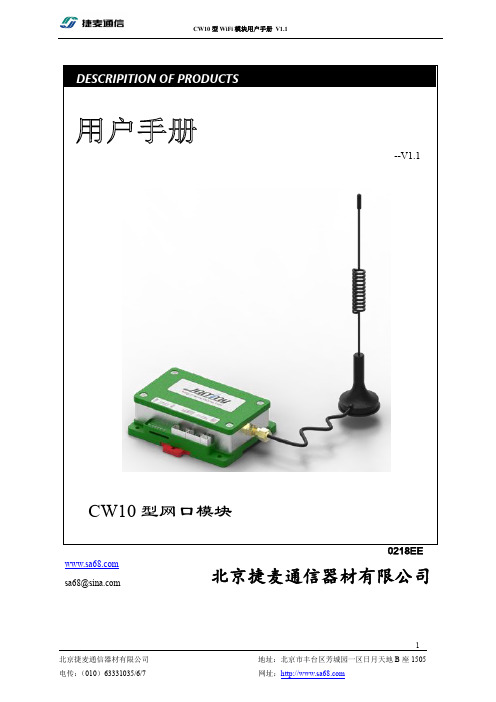
捷麦 CW10 型 WiFi 模块用户手册说明书
--V1.1CW10型网口模块 DESCRIPITION OF PRODUCTS北京捷麦通信器材有限公司 *************版权声明北京捷麦通信器材有限公司版权所有,并保留对本手册及本声明的最终解释权和修改权。
本手册的版权归北京捷麦通信器材有限公司所有。
未得到北京捷麦通信器材有限公司的书面许可,任何人不得以任何方式或形式对本手册内的任何部分进行复制、摘录、备份、修改、传播、翻译成其它语言、将其全部或部分用于商业用途。
免责声明本手册依据现有信息制作,其内容如有更改,恕不另行通知。
北京捷麦通信器材有限公司在编写该手册的时候已尽最大努力保证其内容准确可靠,但不对本手册中的遗漏、不准确或印刷错误导致的损失和损害承担责任。
我们会经常对手册中的数据进行检查,并在后续的版本中进行必要的更正。
欢迎您提出宝贵意见。
技术支持北京捷麦通信器材有限公司建立了以总部技术支持中心、区域技术支持中心和本地技术支持中心为主体的完善的服务体系,并提供电话热线服务。
您在产品使用过程中遇到问题时可随时与北京捷麦通信器材有限公司技术支持服务热线联系。
此外,您还可以通过北京捷麦通信器材有限公司网站及时了解最新产品动态,以及下载需要的技术文档。
北京捷麦通信器材有限公司:地址:北京市丰台区芳城园一区日月天地B座1505邮编:100017电话:************/6/7传真:************E-mail:****************网站:阅读指南手册目标通过阅读该用户手册,可以了解CW10的外观结构及安装、知道CW10如何与PC计算机连接通信、熟悉CW10的各种工作模式及其参数意义,会使用参数配置软件完成对CW10的参数操作,依据常用功能的调试流程应用CW10产品的基本功能。
使得用户完全能够应用本产品所提供的所有功能。
阅读对象本手册为具有一定工控背景知识的工程人员、安装人员及电气人员编写,其内容涵盖了CW10的安装、功能模式讲解和调试等信息。
西门子W10说明书
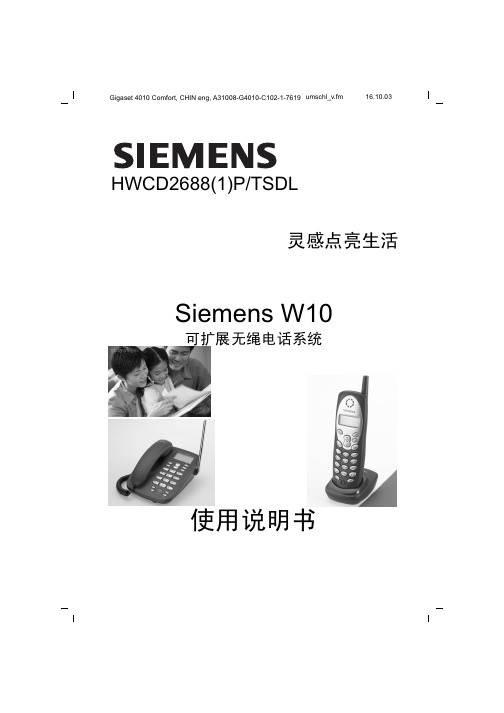
音量 / 调时 按住音量 / 调时键三秒钟 或▼ 按 或▼ 键调整月份设置
音量 / 调时 按音量 / 调时键去到日期设置 或▼ 按 或▼ 键调整日期
音量 / 调时 按音量 / 调时键去到小时设置 或▼ 按 或▼ 键调整小时
音量 / 调时 按音量 / 调时键去到分钟设置 或▼ 按 或▼ 键调整分钟 ( 或按退出键退出设置 )
密码锁 密码锁 ( 座机 ) 预约 座机使用中 手机待用 ( 手机 )
3
Gigaset W10, CS, A31008-G4010-C102-1-7619
vorberei.fm
27.10.03
使用前的准备
按下按键
功能键和指示灯说明
手机功能键说明
I P 号码存储或拨出 - 进入电话簿 / 设置程序 - 在设置模式中确定已选择的选项 - 离开程序 - 手机跟座机对讲 频道 / 查询 ( 电话簿 / 来电显示记录 / 去电记录 ) 挂断 / 删除 / 手机注册 - 重拨 - 拨号或储存电话时加入暂停 通话 / 挂线 - 来电 进入来电记录模式 - 去电 进入去电记录模式 - 通话时调较音量 - 上下浏览 / 选择 显示其余的电话号码
4
Gigaset W10, CS, A31008-G4010-C102-1-7619
vorberei.fm
27.10.03
使用前的准备
按下按键
通话暂侯 - 来电 进入来电记录模式 - 去电 进入去电记录模式 - 上下浏览 / 选择 - 重拨 / 暂停 - 储存电话号码上加入暂停 挂断 显示其余的电话号码
设置 ...............................................6 音频 / 脉冲 选 择 ...................6 挂断时间 选择 ........................6
卫泉系列产品简介说明A

基本配置:无电系列
1)世韩50g低压膜 2)豪华双水龙头 3)3.2塑胶压力桶 4)自动冲洗 适用于:家庭厨房做饭 及饮用水
使用条件:原水压力达 到2.5公斤方可使用
规格参数:
出水量:16L/h 规格:320×420×100 无电式
卫泉RO纯水系列产品及说明
WQ-RO1
基本配置:
卫泉RO商用系列产品及说明
WQ-RO200G
基本配置: 1)自动冲洗 2)外置11G压力桶 3)适合100-150人左右 饮水使用。
规格参数: 出水量:31L/h 规格:400×220×850
卫泉RO商用系列产品及说明
WQ-RO600G
基本配置: 1)自动冲洗 2)外置11G压力桶 3)适合300人左右饮水 使用。
基本配置: 七道九级
1)高品质精滤PP棉 2)纯正椰壳活性炭 3)KDF复合装置 4)离子交换装置 5)纳米级能量球 6)矿化球 7)纳米银布 8)UF超滤装置 适用于:家庭厨房用水
规格参数:
出水量:200L/h 规格:400×200×480 1箱4台
卫泉活化直饮系列产品及说明
WQ-970C基本配置: 七道九级来自卫泉RO商用系列产品及说明
WQ-RO100G
基本配置:
1)自动冲洗 2)外置11G压力桶 3)适合50人左右饮水
规格参数:
出水量:15.8L/h 规格:400×220×850
卫泉RO商用系列产品及说明
WQ-RO150G 基本配置: 1)自动冲洗 2)外置11G压力桶 3)适合100人左右饮水
规格参数: 出水量:23L/h 规格:400×220×850
WQ-1500
卫泉中央机系列产品及说明
RC4 中文操作手册
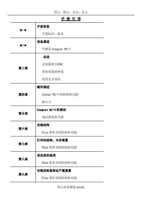
手册引导手册信息手册标识、版本设备描述什麽是Congrav RC-4总述总电源和24VDC使用电缆的种类使用安全须知硬件描述Conrav RC-4的机构和功能插入卡Congrav RC-4的调试调试和软件升级安装结构F1xx菜单页的机构和功能打印机结构,内存重置F2xx菜单页的机构和功能设定值和选项F3xx菜单页的机构和功能安装实际值和总产量重置F4xx菜单页的机构和功能单台加料器的操作Kxx1和Kxx2菜单页的机构和功能报警报告和开机条件Fxx5和Kxx5菜单页的机构和功能硬件结构数字输入输出的结构模拟输入输出的结构接口结构校正参数/附加参数F6xx菜单页的机构和功能硬件测试功能软件的测试功能和状态指示技术数据和零件清单模式显示清单菜单页清单内容提要1介绍1.1手册结构1.2补充文件1.3操作手册使用人群1.4手册中使用的信号和警示1.5使用的方式和缩写1.6版本附件2设备描述2.1目的2.2潜在的危险3总述3.1电源3.2外加24VDC3.3使用的电缆型号3.4安全须知3.4.1Congrav RC-4使用安全须知3.4.2安装安全须知3.4.3接线安全须知3.4.4使用和操作安全须知4硬件描述4.1Congrav RC-4:类型4.2Congrav RC-4A:显示和按键4.2.1集成按键及其功能4.2.2显示和功能组成4.3参数更改4.3.1数字输入4.3.2固定参数设置的选择4.3.3如果….,更改参数不被接受4.4Congrav RC-4B:4.5Congrav RC-4的插卡槽4.5.1现场的可能连线4.6Congrav RC-4的基本功能4.6.1插入卡RC4-MSIO4.6.1.1XS1.1:与主计算机的连接4.6.1.2XS1.2:与ISC现场总线的连接4.6.1.3XS1.3:与调试解调器和工控电脑的连接4.7Congrav RC-4的选项卡4.7.1CDIO插入卡4.7.2DIOP插入卡4.7.2.1输入输出模式-数字式RC-4的终端功能4.7.3ANOP插入卡4.7.3.1输入输出模式-模拟式RC-4的终端功能4.7.4Profibus模式5调试5.1安装5.2调试,Congrav RC-4的开机5.3Congrav RC-4:软件升级5.4ISC-CM:软件升级6菜单页F100安装结构6.1F110:安装模式6.2模拟结构6.3F120:主计算机操作6.4F130:显示内容改变6.5连锁停机6.6时间和日期6.7F150:配方处理6.7.1设定值斜线,设定值阈值6.7.2调试操作7F200:打印机结构,内存值重设7.1打印功能7.2F210:如何清除记忆内容8F300:设定值输入和选择8.1安装设定值8.2加料器设定值8.2.1`设定值的模拟控制8.2.2设定值斜线,设定值阈值(菜单页F150)8.3选项8.4F310:滞后时间8.5报警停机9F400:安装的实际值,总产量重设9.1F430:总产量重设10单台加料器操作10.1加料器页的抬头10.2Kxx0:加料器控制10.3操作功能10.3.1开机 5410.3.2停机 5410.3.3报警重设10.3.4补料 5510.3.5删除 5510.3.6开始试样10.3.7开始去皮10.3.8右侧行实际值的显示10.4Kxx1:产品参数10.4.1自动去皮10.4.2检查最大输出10.4.3堆积密度10.4.4体积最大输出10.4.5十进制转换10.4.5.1十进制转换的设置10.4.6模式 5910.4.6.1失重式加料(GF)10.4.6.2体积式控制(VR)10.4.6.3体积式设置(VS)10.4.6.4排料(DI)10.4.6.5检查最大输出(CM)10.4.6.6重量式排料(GD)10.4.6.7体积式加料(VF)10.4.6.8测量(M)10.4.6.9运行过程中GF和VF模式转换10.5Kxx2:控制参数10.5.1PID控制的设置10.5.1.1控制成套配合10.5.1.2重量式计算最大输出10.5.1.2.1CM值的存储11F500:报警报告和开机条件11.1报警报告11.2缺省的开机条件11.3系列驱动控制操作的错误代码11.3.1系列变频器11.3.2振动放大器控制器ISC-VC11.4Kxx5:报警结构12硬件结构12.1 Kxx8:ISC-CM(-A)的硬件结构12.1.1 速度输入12.1.2 传感器(重量读取)的结构12.1.3 驱动控制器12.1.4 ISC-CM-A模拟输入输出的结构12.1.4.1 ISC-CM-A上单台控制的选项12.1.4.2 Kxx8:模拟输入12.1.4.3 Kxx8:模拟输出12.2 ANOP模拟输入输出的结构12.2.1 安装控制和安装的实际值12.2.1.1 菜单页F190的参数12.2.2 ANOP的组分功能12.2.2.1 模拟输入:模拟单台控制12.2.2.2 模拟输出:总操纵量或实际值12.2.2.2.1 模拟输出信号范围的定义12.3 CDIO的数字输入输出12.4 DIOP的数字输入输出12.4.1 DIOP:功能描述12.5 ISC现场总线机构12.5.1 如果构建总线通讯12.5.2 总线通讯的关闭12.6 调试解调器的机构12.7 主计算机操作机构12.7.1 MISO卡上的主计算机接口12.7.2 Profibus DP操作结构12.7.3 以太网接口的结构13校正程序13.1加料器参数13.2加料器参数功能解释13.2.1CP02-加料范围13.2.2CP04-欠载13.2.3CP03-最大输出量13.2.4CP05-过载13.2.5CP06-粗去皮13.2.6CP07-平均重量取数13.2.7CP08-总产量累计分值13.2.8CP09-最小速度13.2.9CP010-最大速度13.2.10CP11-控制偏差13.2.11CP12-报警停机滞后时间13.2.12CP13-联锁类型13.2.13CP14-实际值指示13.2.14CP15-杠杆臂值13.2.15CP16-料斗内容13.2.16CP17-最小补料料位13.2.17CP18-最大补料料位13.2.18CP19-Window/K1/滤波IDL/F, AED 13.2.19CP20-数字速度13.2.19.1标准速度监控13.2.19.2FlexWall-Plus加料器的运动监控13.2.19.3数字式速度取数13.2.19.4推荐输入13.2.20CP21-最大补料时间13.2.21CP22-补料优化13.2.22CP23-稳定时间13.2.23CP24-测样时间13.2.24CP25-防振(AV)切断时间13.2.25CP26-PID控制器接近时间13.2.26CP27-控制器自动化13.2.26.1控制器自动化13.2.26.2开机自动化13.2.26.2.1重复的开机自动化13.2.26.2.2总体开机自动化13.2.27CP28-滤波限制13.2.28CP29-实际值的接纳13.2.29CP30-总操纵量的接纳13.2.30CP31-体积控制(VR)实际值的接纳13.2.31CP32-开机滞后时间13.2.32CP33-称重桥(LWB)的长度13.2.33CP34-重量测试值(WTV)13.2.34CP35-摄取(AP)13.2.35CP36-自动去皮范围13.2.36CP37-无负载时间自动去皮13.2.37CP38-有比例的皮带速度13.2.38CP39-皮带长度13.2.39CP40-dead time way13.3附加参数13.3.1AP01-05 校正13.3.2AP11-可用的称重范围13.3.3AP12-drop out13.3.4AP13-速度模式13.3.5AP14-滑动影响13.3.6AP15-滑动值13.3.7AP16-速度接纳性13.3.8AP17-无负载时间13.3.9AP18-AT时间13.3.10AP19-驱动控制2最小13.3.11AP20-驱动控制2最大14硬件测试功能14.1F140:输入输出测试-外围(安装)14.2Kxx3:输入输出状态显示-外围14.3Kxx4:测试功能和模拟14.3.1模拟模式14.3.2输入输出测试(加料器)15名词解释附件11915.1技术数据15.2电磁兼容性15.3零配件清单15.4可能显示的模式清单15.5菜单页清单插图表图4-1:Congrav RC-4后部视图图4-2:Congrav RC-4后部视图(带ProfiBus模式)1 总介绍1.1手册的结构现有的操作手册包括:RC-4的:技术操作和RC-4 HGC软件(其版本请参见封页)按照下列顺序,每章独立描述一个完整的主题:设备的描述使用特性硬件执行硬件功能定义操作软件描述参数描述和结构例举1.2附加文件ISC系统的描述ISC-CM,ISC-FC和ISC-VC的技术手册相应主计算机程序手册1.3操作手册所适用的人群操作手册适用于以下两组人群:经过授权和培训过的专业技术人员来进行安装和其它电气工作。
施耐德TeSysF接触器、热过载继电器技术资料

Schneider Electric
i
选型指南
TeSys 接触器
115 至 2750 A
应用
控制所有类型的电动机,适用于标准和重载应用 控制电阻、电感和电容性电路:加热、照明、功率因数补偿、变压器 常规-备用电源
额定工作 Ie max AC-3 电流 (Ue ≤ 440 V) Ie max AC-1 (θ ≤ 40 °C) 额定工作 电压 极数
425 kW 750 kW 800 kW 800 kW 700 kW 750 kW 670 kW
500 kW 900 kW 900 kW 900 kW 900 kW 900 kW 750 kW
4 瞬时触点构成: 2 N/C + 2 N/O、 3 N/O + 1 N/C、 1 N/O + 3 N/C 或 4 N/O
LR9-F LT6
LA4-FWB 根据控制电路,带或不带
LC1-F115
用于客户组装
LC1-F150
LC1-F185
LC1-F225
LC1-F265
LC1-F330
1/2
Schneider Electric
0
400 A 500 A
500 A 700 A
630 A 1000 A
780 A 1600 A
TeSys F !
®
"#
!
目录
0
TeSys F
页码
F 型接触器与可逆接触器
b 选型指南 . . . . . . . . . . . . . . . . . . . . . . . . . . . . . . . . . . . . . . . . . . . . . . . . . . . . . . 1/2 b 特性 . . . . . . . . . . . . . . . . . . . . . . . . . . . . . . . . . . . . . . . . . . . . . . . . . . . . . . . . . . 1/4 b 接触器选型指南 v 用于至 450 kW/1000V 的电动机控制, AC-3 类别 . . . . . . . . . . . . . . . . . . . 1/12 v 用于 200A 至 1600A 的电路控制, AC-1 类别 . . . . . . . . . . . . . . . . . . . . . . . 1/13 b 根据电气寿命选型 v AC-3 使用类别 . . . . . . . . . . . . . . . . . . . . . . . . . . . . . . . . . . . . . . . . . . . . . . . 1/14 v AC-1 使用类别 . . . . . . . . . . . . . . . . . . . . . . . . . . . . . . . . . . . . . . . . . . . . . . . 1/15 v AC-2 或 AC-4 使用类别 . . . . . . . . . . . . . . . . . . . . . . . . . . . . . . . . . . . . . . . . 1/16 v DC-1 至 DC-5 使用类别 . . . . . . . . . . . . . . . . . . . . . . . . . . . . . . . . . . . . . . . . 1/18 b 用于电动机控制的可逆接触器, AC-3 类别 v 至 147kW/1000V . . . . . . . . . . . . . . . . . . . . . . . . . . . . . . . . . . . . . . . . . . . . . 1/20 b 用于电源转换的接触器组, AC-1 类别 v 200A 至 350 A . . . . . . . . . . . . . . . . . . . . . . . . . . . . . . . . . . . . . . . . . . . . . . . 1/21 b 可逆接触器和电源转换接触器组的装配元件 . . . . . . . . . . . . . . . . . . . . . . . . . . 1/22 b 辅助模块与附件 . . . . . . . . . . . . . . . . . . . . . . . . . . . . . . . . . . . . . . . . . . . . . . . . 1/27 b F 型接触器线圈 v 交流 50/60Hz 线圈 . . . . . . . . . . . . . . . . . . . . . . . . . . . . . . . . . . . . . . . . . . . . 1/34 v 交流 40-400Hz 线圈 . . . . . . . . . . . . . . . . . . . . . . . . . . . . . . . . . . . . . . . . . . . 1/35 v 交流 40-400Hz 线圈,特殊应用 . . . . . . . . . . . . . . . . . . . . . . . . . . . . . . . . . . 1/38 v 直流线圈 . . . . . . . . . . . . . . . . . . . . . . . . . . . . . . . . . . . . . . . . . . . . . . . . . . . 1/40 v 直流线圈,特殊应用 . . . . . . . . . . . . . . . . . . . . . . . . . . . . . . . . . . . . . . . . . . 1/42 v 宽幅电压直流线圈,特殊应用 . . . . . . . . . . . . . . . . . . . . . . . . . . . . . . . . . . . 1/43 b 尺寸、安装与线路图 . . . . . . . . . . . . . . . . . . . . . . . . . . . . . . . . . . . . . . . . . . . . 1/44 b 大功率电源转换触器组,交流或直流 v 概述 . . . . . . . . . . . . . . . . . . . . . . . . . . . . . . . . . . . . . . . . . . . . . . . . . . . . . . . 1/54 v 型号 . . . . . . . . . . . . . . . . . . . . . . . . . . . . . . . . . . . . . . . . . . . . . . . . . . . . . . . 1/55 v 尺寸、线路图 . . . . . . . . . . . . . . . . . . . . . . . . . . . . . . . . . . . . . . . . . . . . . . . . 1/56 b 星-三角起动器,用户自行组装 v 型号 . . . . . . . . . . . . . . . . . . . . . . . . . . . . . . . . . . . . . . . . . . . . . . . . . . . . . . . 1/59 v 尺寸、安装、线路图 . . . . . . . . . . . . . . . . . . . . . . . . . . . . . . . . . . . . . . . . . . 1/62
F601超声波流量计说明书
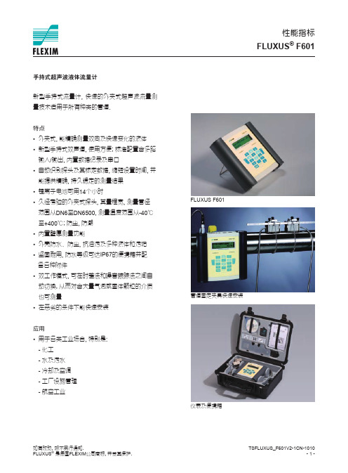
FLUXUS® F601
技术参数
FLUXUS 款式
手持式
F601
性能指标
测量 测量原理 流速 重复性 精度 - 体积流量
介质 温度补偿 主机 电源
电池
功耗 通道 信号平均 测量速率(单通道) 响应时间 材质 防护等级 (根据EN60529) 重量 固定 工作温度 显示 工作语言 测量功能 测量量 累积量 计算功能 诊断功能 数据记录 可记录的参数 容量
体积流量, 质量流量, 流速, 能量流量 体积, 质量, 能量 (可选) 平均值, 差值, 总和 声速,信号幅度,SNR,SCNR,时间或幅度的标准差
所有测量量及累积量 >100,000条测量量
TSFLUXUS_F601V2-1CN-1010 --
如有改动�, 恕不另行通知. FLUXUS® 是德国FLEXIM公司商标, 并受其保护.
快速管道固定夹具
串口数据包
卷尺
c用on户ne手ct册or,快bo速ar操d a作t 指the南 u输pp出er适s配ide器of the flowm输e入ter适配器
---------√√√√√tspbQfusfmf(rlaloeoeoasatuesrwrewrwtnaittiaicareaesmmnesklnlprmsruFyeeddiodnsratitaarixueeugnntttcrrapagpucsepiaahkkptrlasliyoie,ttfep,reQemepsquooauiwcuneknednrtScicncythagaaMrbftiiln,xeGsQtuu)rideefor -√fastening shoes and chains --√- mu( stereaarnsmsudraiunncgueatral,fprQeequuiceknScytaMrt ,GQu)ide -
西门子变频器介绍
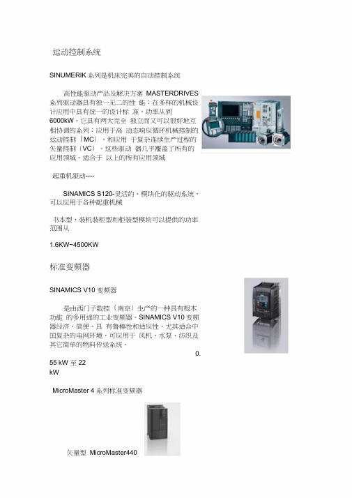
运动控制系统SINUMERIK系列是机床完美的自动控制系统高性能驱动产品及解决方案MASTERDRIVES 系列驱动器具有独一无二的性能:在多样的机械设计应用中具有统一的设计标准,功率从到6000kW。
它具有两大完全独立而又可以很好地互相协调的系列:应用于高动态响应循环机械控制的运动控制〔MC〕,和应用于复杂连续生产过程的矢量控制〔VC〕。
这些驱动器几乎覆盖了所有的应用领域。
适合于以上的所有应用领域起重机驱动----SINAMICS S120-灵活的、模块化的驱动系统,可以应用于各种起重机械书本型,装机装柜型和柜装型模块可以提供的功率范围从1.6KW~4500KW标准变频器SINAMICS V10 变频器是由西门子数控〔南京〕生产的一种具有根本功能的多用途的工业变频器。
SINAMICS V10变频器经济、简便、具有鲁棒性和适应性,尤其适合中国复杂的电网环境,可应用于风机、水泵、纺织及其它简单的物料传送系统。
0.55 kW 至22kWMicroMaster 4系列标准变频器矢量型MicroMaster440200V-240V ±0%,单相/三相,交流,0.12kW-45kW ;380V-480V ±10%,三相,交流,0.37kW-250kW ;节能型MicroMaster430380V-480V ±10%,三相,交流,根本型MicroMaster420200V-240V ±10%,单相/三相,交流,0.12kW-5.5kW ; 380V-480V±10% , 三相,交流,紧凑型MicroMaster410200V-240V ±10%,单相,交流,SINAMICS G110 系列变频器是西门子公司统一的模块化系统的一局部,可以派生出多种多样的结构,满足各种机械和设备控制的需要。
SINAMICS驱动装置采用以系统为基础的创新设计,即使是最小的G110变频驱动装置,其电源,电压和技术功能都是符合标准规格的。
禹鼎遥控器说明
品牌:禹鼎原产地:台湾控制距离:可达100米安全码:43亿种以上安全码出厂永不重复使用温度:-35℃至+80℃(不考虑电池耐温) 防护等级:IP65(防尘、防水性能卓越)发射器电源:直流3V(2节碱性5号电池)接收器电源:交流220V/380V可选择,或交、直流12V输出触点容量:5安培全密封式继电器输出(使用交流250V/10A继电器,5安培保险丝)。
产品规格:一.外形尺寸发射器尺寸:16.4x7.5x4.6厘米,重量:约300克(含电池)接收机尺寸:18.5x8.5x8.5厘米,重量:550克二.功能说明具有8只操作按键,其中7只单速按键,1只总停;控制点数达9个,每个点最多有三种控制方式;带有电池电压警示装置,在电压不足时能自行切断电路;安全钥匙开关,防止未授权者使用。
三.特别功能可由电脑接口设定内部功能,例如:开机方式和按键方式;上/下、东/西、南/北可设定为捺跳、普通等功能及是否互相抑制;备用1键可设定为开机、加速、捺跳、普通等功能。
四.标准配置1.发射器……1支2.接收机……1部3.接收机自带连接电缆……1米4.操作及维护手册……1本5.发射器透明防护套……1个五.使用范围单速电动葫芦单梁起重机;双速电动葫芦单梁起重机;单勾、单速双梁起重机;控制9个接点以下的工业控制遥控用。
产品优点:起重机械控制系统用工业遥控器改造后,可大大改善操作人员的劳动条件和环境,减轻劳动强度,增加安全指数,并且可以提高生产效率,节约劳动力,树立单位的企业形象等特点。
禹鼎工业遥控发射器体积小、重量轻,携带方便;质量稳定、安全性能好,使用放心;价格便宜、售后服务好,使用成本低廉;因而深受工业企业和生产单位的青睐。
以禹鼎遥控器F21-E(1B)型为例,主要特点是:1.发射器表现安全、高效率;2.低谐波的调频的发射电路;3.具备高稳定性和省电的特点;4.配合高增益高品质因素值的校正天线,能以微弱的发射功率传送信息;5.使用40串列位无编码晶片,配合时序电路,电压检测,电源控制,模拟线性电路可快速精确编码,降低发射杂讯;6.具备自动频率较正,自动调整校正等功能;6.按下开机键,发射器电源自动起动,按下停止键则自动关断发射机电源,节电耐用;8.接收器使用高选择,高增益、低杂音,低假象的窄频接收电路;9.可在宽广的温度范围内长期动作,配合高品质因素值的校正天线,能更好摒除外来干扰;10.对于温度,电压及长时间所造成的频率的调变率的偏移,能有效地自动校正;11.解码继电器把许多快速元件浓缩在一只IC晶片中,增强了可靠度及抗干扰性,对电码具有高度的选择判断能力; 12.产品体积小、轻巧灵活,性能稳定。
CDC10系列交流接触器
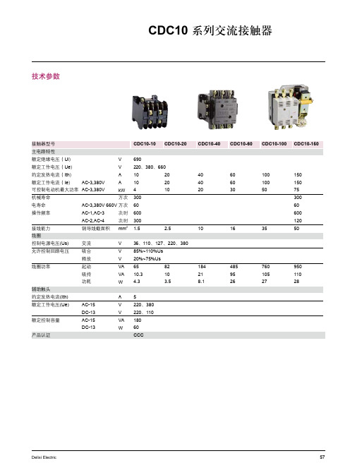
辅助触头 常开NO 常闭NC
定货编码
4 10 20 30 50 75
10 20 40 60 100 150
2 2 2 2 2 2
2 2 2 2 2 2
CDC101022*△ CDC102022*△ CDC104022*△ CDC106022*△ CDC1010022*△ CDC1015022*△
注:极数3极为常规极数,在型号中不表示, 对于CDC0定货代码中的“*”可由线圈电压代码来表示,“△”可由本体类型代码来表示
线圈电压代码 线圈电压 (V) * 本体类型代码 本体类型 △
36 C 防潮型(TH) T
0 F
7 S 标准型 不表示
0 M
380 Q
60
Delixi Electric
36、0、7、0、380 85%~0%Us 0%~75%Us 65 0.3 4.3 5 0、380 0、0 80 60 CCC 8 0 3.5 84 8. 485 95 6 760 05 7 950 0 8
Delixi Electric
57
CDC10 系列交流接触器
技术参数
接触器型号 主电路特性 额定绝缘电压(Ui) 额定工作电压(Ue) 约定发热电流(Ith) 额定工作电流(Ie) 机械寿命 电寿命 操作频率 接线能力 线圈 控制电源电压(Us) 允许控制回路电压 线圈功率 交流 吸合 释放 起动 吸持 功耗 辅助触头 约定发热电流(Ith) 额定工作电压(Ue) 额定控制容量 产品认证 AC-5 DC-3 AC-5 DC-3 A V V VA W V V V VA VA W AC-,AC-3 AC-,AC-4 铜导线截面积 AC-3,380V 可控制电动机最大功率 AC-3,380V V V A A kW 万次 AC-3,380V 660V 万次 次/时 次/时 mm
WX10水泵准备手册说明书

Manual de preparaciónWX10POR LA SEGURIDAD DEL CLIENTE.La preparación adecuada y el servicio previoa la entrega son esenciales para la seguridad del usuario y la fiabilidad de su bomba de agua.Cualquier error o descuido por parte deltécnico o cliente al ensamblar o preparar una unidad nueva puede resultar en una operación deficiente, daño al motor, o heridas al usuario.Nota Precautoria:La preparación inadecuada o un mal servicio previo a la entrega pueden crear una condición insegura que puede ocasionar al usuario heridas serias e incluso la muerte.Siga con cuidado los procedimientos y precauciones descritos en este manual y enel manual de propietario.POR SU SEGURIDADAlgunas de las más importantes precauciones de seguridad se describen a continuación.Sin embargo, no podemos advertirle sobre todos los posibles riesgos que pueden surgir mientras realiza la preparación ó el servicio previo a la entrega. Solamente usted puede decidir realizar o no una tarea asignada.Como utilizar este manualSiga la secuencia de los pasos tal y como se muestran. No omita ni uno solo de los pasos. La secuencia ha sido establecida para asegurar el correcto funcionamiento dela unidad. Cada paso está formado por 3 componentes: • Subtítulo:En negritas, se describe brevemente el paso. Están destinados para que el usuario identifique el procedimiento a seguir.• Texto descriptivo:Este texto explica a detalle lo que se debe realizar en cada paso.La explicación debe ser una guía para el usuario que necesita información adicional. • Ilustraciones:Las fotografías e ilustraciones refuerzan el contenido de los subtítulos y el texto a detalle. Como desempacar y como preparar subomba de agua.Lista de artículos necesarios para la activación de su nueva bomba de agua.1. Un bidón con gasolina fresca.2. Una botella de aceite 10W-303. Un embudo pequeño.4. Franelas para limpiar salpicaduras y/oderrames.De lectura a su manual de usuario para aprender a utilizar su bomba de agua nueva y tomar todos los conocimientos de las características de este.Registre su nueva bomba de agua enviando el talón del alta que viene en su póliza de garantía a distribuidor que efectuó la venta del producto.Desembalaje de la bomba de agua.Antes de abrir la caja verifique el número de motor y de chasis de su producto conforme la factura que se le entrego.Abra la caja con una navaja y tenga cuidado de no afectar el producto y sus accesorios.Revise que la Bomba de agua no tenga ralladuras o golpes antes de activarla, si así fuese, de aviso al distribuidorDentro encontrara una bolsa la cual contiene lo siguiente:•Manual de propietario•Filtro para sedimentos•Bolsa con conexiones y abrazaderas para manguera.Nota:Todo producto Honda es puesto en funcionamiento y probado desde fábrica.Después de la prueba, la gasolina y el aceite son drenados antes de ser empacados.Encontrar una pequeña cantidad de residuos de aceite y/o gasolina es norma.Activación de su bomba de agua.Nota:Honda recomienda la utilización de partes genuinas para todos sus productos a fin de respetar la garantía.Todas las bombas de agua Honda cuentan con una etiqueta de papel de color amarillo que indica que se agregue aceite al motor antes de su uso.Pasos para la colocación de aceite de motor.1. Retire el tapón de aceite que está ubicadadel lado derecho de su orilladora.2. Comience a llenar el depósito con aceite10W-30 recomendado por el fabricante. 3. El depósito quedara lleno una vez que elaceite este tocando la última cuerdadonde se enrosca la tapa de aceite.4.Coloque el tapón del aceite.5. Limpie cualquier derrame o salpicadurade aceite que exista.6. En este paso usted podrá retirar laetiqueta que indica la revisión de aceite.El sistema de alerta de aceite parará automáticamente el motor antes de que el nivel de aceite caiga por debajo de los límites de seguridad.Sin embargo, para evitar la inconveniencia de una parada inesperada, compruebe con regularidad el nivel de aceite.Pasos para la colocación de Gasolina.Llene el tanque de la gasolina con gasolina fresca de un contenedor limpio.Nota:No sobre llene el tanque de gasolina.Limpie cualquier derrame o salpicadura de gasolina que exista.Coloque el tapón de gasolina y gírelo hasta que quede completamente cerrado.Utilice gasolina sin plomo de 91 octanos o superior.No emplee nunca gasolina pasada o sucia ni mezcla de aceite/gasolina.Evite la entrada de suciedad o agua en el depósito de combustible.Si va a utilizar el equipo de forma intermitente o poco frecuente, consulte la sección de combustible del capítulo ALMACENAJE del manual de propietario para obtener más información relativa al deterioro del combustible.Conexión de la manguera de succión• Utilice una manguera (disponible comercialmente), conector de manguera y abrazaderas proporcionadas en la bomba como accesorio.•La manguera de succión debe ser reforzada, de estructura irrompible.•La longitud de la manguera no debe ser más de la necesaria, ya que elrendimiento es mejor cuando la bombano está muy por arriba del nivel del agua. •El tiempo de auto cebado también es proporcional a la longitud de la manguera.El filtro que se proporciona con la bomba debe conectarse en el extremo de la manguerade succion con una abrazadera, de la manera en que se muestra.Advertencia:Instale siempre el filtro sobre el extremo de la manguera de succion antes de bombear.El filtroseparar los sedimentos que puedan ocacionar atascos o daños al impulsor.Conexión de manguera de descarga. •Utilice una manguera (disponible comercialmente), conector de mangueray abrazaderas proporcionadas en labomba como accesorio.•Una manguera corta o de gran diámetro es más eficiente.•Una manguera larga o de pequeño diámetro aumentara la fricción del fluidoy reducirá la potencia de la bomba.Cebado de la bomba.1. Retire el tapón del orificio del llenado deagua del cebado.2. La cámara de la bomba debe cebarse conagua antes de iniciar el funcionamiento3. Una vez llena el área de la cámara decebado, retire el bidón y coloque el tapón del orificio.Advertencia:No trate nunca de poner en funcionamiento la bomba sin agua de cebado ya que la bomba se calentara excesivamente.La operación de la bomba en seco durante un largo periodo de tiempo destruirá el empaque de la bomba.Si la bomba a estado funcionado en seco, pare inmediatamente el motor y deje que la bomba se enfrié antes de añadir agua de cebado.Encendido de su bomba de aguaEn cualquier momento que active su bomba de agua, asegúrese que esta se encuentre en un lugar abierto, alejado de puertas y ventanas.Nunca opere una bomba de agua dentro de una casa, garaje, sótano, semisótano, o cualquier lugar cerrado o parcialmente cerrado.Para encender la bomba de agua realice los siguientes pasos:1. Para arrancar el motor coloque la palancadel ahogador en la posición ACTIVADOcomo se muestra en la imagen.2. Aplique bombeo a la perilla que seencuentra en el carburador para cargar a este con el combustible hasta que usted observe que está lleno.Nota:Incluso aunque presione demasiadas veces la bomba de cebo, el combustible extra volverá al depósito de combustible.Si la bomba de cebo no se presiona las veces suficientes, el motor podría no arrancar.3. Coloque el interruptor del motor a laposición ON.4. Tire ligeramente la empuñadura de lapolea hasta sentir resistencia mientrassujeta el mango; a continuación tire confuerza hacia fuera como se muestra.Nota:•No dejar que la empuñadura delarrancador vuelva a su lugar con fuerza.Haga que retorne con suavidad para evitardaños en el arrancador.5. Si tiene el ahogador ACTIVADO almomento de arrancar el generadordesactívelo gradualmente a medida quese vaya calentando el motor.Nota:El jalar la polea de encendido del motor másde una vez quiere dar a entender que es elprimer encendido y/o que la unidad se quedosin gasolina.Acelerador.Active la palanca de aceleración del motor de su bomba de agua para que esta comience a funcionar.Acelerador en velocidad baja.Acelerador en velocidad alta.Apagado de su bomba de agua.Para parar el motor en situaciones normales emplee el procedimiento siguiente. 1. Coloque el interruptor del motor en laposición OFF.Refiérase al manual de propietario para mayores detalles.。
松下 RC10 说明书
菜单项目......................................... 21 菜单 .................................................21 BLACK ............................................. 21 FLARE .............................................22 GAMMA ...........................................22 WHITE .............................................23 KNEE...............................................24 SHUTTER .......................................24 SHAD ..............................................25 MATRIX ...........................................25 DTL .................................................. 26 SKIN DTL ........................................26 FUNC ..............................................27 SYSTEM..........................................28
2 打开摄录一体机电源之后,再打开本机电源。
<注意>
西门子M440变频器参数

西门子M440变频器参数
电流电压开关:1设为OFF(下),2设为ON(上),
变频器参数有四个访问级:标准级、扩展级、专家级、维修级,取决于P003的设定。
变频器复位:P0010=30 P0970=1,如果要设置P304-P311参数需要将
19注释:这种设置的出发点是,只有当发生故障(F0003等)时变频器已经处于“运行(RUN)”状态下,它才能再启动。
变频器将确认故障,并在“电源中断”或者“电源隐匿”之后重新启动。
这种情况下需要ON命令一直加在数字输入端(DIN)
“电源隐匿”是指,电源中断,,并在BOP的显示变暗和消失之前重新加上电源(时间非常短暂地电源中断时,直流回路的电压不会完全消失)。
- 1、下载文档前请自行甄别文档内容的完整性,平台不提供额外的编辑、内容补充、找答案等附加服务。
- 2、"仅部分预览"的文档,不可在线预览部分如存在完整性等问题,可反馈申请退款(可完整预览的文档不适用该条件!)。
- 3、如文档侵犯您的权益,请联系客服反馈,我们会尽快为您处理(人工客服工作时间:9:00-18:30)。
FREQUENCY (MHz)
FREQUENCY (MHz)
FREQUENCY (MHz)
W4F601-RC-10
10000 1000 100 10 0.1 1 10 100 1000 10000
Normal Mode Common Mode
W4F222-RB-10
10000 1000 100 10 0.1 1 10 100 1000 10000
100 10 1 0.1
100 10 1 0.1
Common Mode
Normal Mode
Normal Mode
Normal Mode
10
100
1000
10000
1
10
100
1000
10000
1
10
100
100010000源自FREQUENCY (MHz)
FREQUENCY (MHz)
FREQUENCY (MHz)
元器件交易网
WIREWOUND TYPE COMMON MODE FILTER
1. PART NO. EXPRESSION : W4F300-RD-10
(a)(b) (d) (c) (e)(f) (g)
W4 SERIES
(a) Series code (b) Dimension code (c) Material code (d) Impedance code : 300 = 30
IMPEDANCE ( )
IMPEDANCE ( )
100 10 1 0.1 1
Common Mode
IMPEDANCE ( )
100 10 1
100 10 1 0.1
Common Mode
Normal Mode
Normal Mode
Normal Mode
10
100
1000
10000
1
10
100
1000
IMPEDANCE ( )
100 10 1 0.1 1
100 10 1 0.1
100 10 1 0.1
Common Mode
Normal Mode
Normal Mode
Normal Mode
10
100
1000
10000
1
10
100
1000
10000
1
10
100
1000
10000
FREQUENCY (MHz)
Mechanical Performance Test Solderability Test More than 90% of termincal electrode should be covered with solder.
Preheating Dipping Natural cooling
245°C 150°C
17.06.2008
SUPERWORLD ELECTRONICS (S) PTE LTD
PG. 4
元器件交易网
WIREWOUND TYPE COMMON MODE FILTER
8. RELIABILITY & TEST CONDITION :
W4 SERIES
ITEM
Electrical Characteristics Test Z (common mode) DCR I.R. Rated Current
元器件交易网
WIREWOUND TYPE COMMON MODE FILTER
7. CHARACTERISTICS CURVES :
W4 SERIES
W4F300-RD-10
1000 1000
W4F670-RD-10
1000
Common Mode
W4F800-RD-10
元器件交易网
WIREWOUND TYPE COMMON MODE FILTER
5. GENERAL SPECIFICATION : a) Operating temp. : -55°C to +125°C b) Storage temp. : -40°C Max. 70% RH
Normal Mode Common Mode
IMPEDANCE ( )
FREQUENCY (MHz)
IMPEDANCE ( )
FREQUENCY (MHz)
NOTE : Specifications subject to change without notice. Please check our website for latest information.
FREQUENCY (MHz)
FREQUENCY (MHz)
W4F181-RC-10
1000 1000
W4F221-RC-10
1000
Common Mode
W4F261-RC-10
IMPEDANCE ( )
IMPEDANCE ( )
100 10 1 0.1 1
Common Mode
IMPEDANCE ( )
Operating Temperature Storage Temperature Temperature Rise Test
-40°C ~ +85°C -40°C ~ +85°C 30°C max. ( t) 1. Applied the allowed DC current. 2. Temperature measured by digital surface thermometer.
元器件交易网
WIREWOUND TYPE COMMON MODE FILTER
7. CHARACTERISTICS CURVES :
W4 SERIES
W4F281-RC-10
1000 100 10 1 0.1 1 10 100 1000 10000
Normal Mode Common Mode
(e) R : Tape & Reel (f) Rated Current : D = 400mA (g) 10 : Lead Free
2. CONFIGURATION & DIMENSIONS :
A
C
B
E
1
2
G2 H
1
2
D2
4
D2 G1 L
3
4
D1
3
D1
PCB Pattern C D1 D2 E G1 1.90 Ref. G2 0.40 Ref. H 1.60 Ref.
NOTE : Specifications subject to change without notice. Please check our website for latest information.
17.06.2008
SUPERWORLD ELECTRONICS (S) PTE LTD
PG. 2
PERFORMANCE
TEST CONDITION
HP-4291A + HP-16092A
Refer to standard electrical characteristics list
HP-4338B Zentech 702A (Ultra High Resistance Meter) Applied the current to coils the impedance change should be less than ±25% to initial value and temperature rise should not be more than 30°C.
W4 SERIES
6. ELECTRICAL CHARACTERISTICS : Part No. W4F300-RD-10 W4F670-RD-10 W4F800-RD-10 W4F900-RD-10 W4F121-RD-10 W4F161-RC-10 W4F181-RC-10 W4F221-RC-10 W4F261-RC-10 W4F281-RC-10 W4F301-RC-10 W4F361-RC-10 W4F431-RC-10 W4F471-RC-10 W4F551-RC-10 W4F601-RC-10 W4F222-RB-10 Common mode Impedance ( ) 30±25% 67±25% 80±25% 90±25% 120±25% 160±25% 180±25% 220±25% 260±25% 280±25% 300±25% 360±25% 430±25% 470±25% 550±25% 600±25% 2200±25% Test Frequency ( MHz ) 100 100 100 100 100 100 100 100 100 100 100 100 100 100 100 100 100 DCR ( ) Max. 0.20 0.30 0.30 0.30 0.30 0.35 0.35 0.45 0.45 0.45 0.50 0.60 0.60 0.70 0.75 0.80 1.20 Rated Current ( mA ) 400 400 400 400 400 350 350 300 300 300 300 300 300 300 300 300 200 Rated Voltage ( Vdc ) 50 50 50 50 50 50 50 50 50 50 50 50 50 50 50 50 50 Withstand Voltage ( Vdc ) 125 125 125 125 125 125 125 125 125 125 125 125 125 125 125 125 125 IR ( ) Min. 10M 10M 10M 10M 10M 10M 10M 10M 10M 10M 10M 10M 10M 10M 10M 10M 10M
