东睿ARECA SAS8盘位存储
SC8F812x 增强型闪存8位CMOS单片机说明书
V1.0请注意以下有关芯联发公司知识产权政策:(一)芯联发公司已申请了专利,享有绝对的合法权益。
与芯联发公司MCU或其他产品有关的专利权并未被同意授权使用,任何经由不当手段侵害芯联发公司专利权的公司、组织或个人,芯联发公司将采取一切可能的法律行动,遏止侵权者不当的侵权行为,并追讨芯联发公司因侵权行为所受的损失、或侵权者所得的不法利益。
(二)芯联发公司的名称和标识都是芯联发公司的注册商标。
(三)芯联发公司保留对规格书中产品在可靠性、功能和设计方面的改进作进一步说明的权利。
然而芯联发公司对于规格内容的使用不负责任。
文中提到的应用其目的仅仅是用来做说明,芯联发公司不保证和不表示这些应用没有更深入的修改就能适用,也不推荐它的产品使用在会由于故障或其它原因可能会对人身造成危害的地方。
芯联发公司的产品不授权适用于救生、维生器件或系统中作为关键器件。
芯联发公司拥有不事先通知而修改产品的权利。
目录1.产品概述 (1)1.1功能特性 (1)1.2系统结构框图 (2)1.3管脚分布 (3)1.3.1SC8F8121引脚图 (3)1.3.2SC8F8122引脚图 (3)1.4系统配置寄存器 (4)1.5在线串行编程 (5)2.中央处理器(CPU) (6)2.1内存 (6)2.1.1程序内存 (6)2.1.1.1复位向量(0000H) (6)2.1.1.2中断向量 (7)2.1.1.3跳转表 (8)2.1.2数据存储器 (9)2.2寻址方式 (12)2.2.1直接寻址 (12)2.2.2立即寻址 (12)2.2.3间接寻址 (12)2.3堆栈 (13)2.4工作寄存器(ACC) (14)2.4.1概述 (14)2.4.2ACC应用 (14)2.5程序状态寄存器(STATUS) (15)2.6预分频器(OPTION_REG) (16)2.7程序计数器(PC) (18)2.8看门狗计数器(WDT) (19)2.8.1WDT周期 (19)3.系统时钟 (20)3.1概述 (20)3.2系统振荡器 (21)3.2.1内部RC振荡 (21)3.3起振时间 (21)3.4振荡器控制寄存器 (21)4.复位 (22)4.1上电复位 (22)4.2掉电复位 (23)4.2.1掉电复位概述 (23)4.3看门狗复位 (24)5.休眠模式 (25)5.1进入休眠模式 (25)5.2从休眠状态唤醒 (25)5.3使用中断唤醒 (25)5.4休眠模式应用举例 (26)5.5休眠模式唤醒时间 (26)6.I/O端口 (27)6.1I/O口结构图 (28)6.2PORTB (29)6.2.1PORTB数据及方向 (29)6.2.2PORTB模拟选择控制 (30)6.2.3PORTB下拉电阻 (30)6.2.4PORTB上拉电阻 (31)6.2.5PORTB电平变化中断 (31)6.3I/O使用 (33)6.3.1写I/O口 (33)6.3.2读I/O口 (33)6.4I/O口使用注意事项 (34)7.中断 (35)7.1中断概述 (35)7.2中断控制寄存器 (36)7.2.1中断控制寄存器 (36)7.2.2外设中断允许寄存器 (37)7.2.3外设中断请求寄存器 (37)7.3中断现场的保护方法 (38)7.4中断的优先级,及多中断嵌套 (38)8.定时计数器TIMER0 (39)8.1定时计数器TIMER0概述 (39)8.2TIMER0的工作原理 (40)8.2.18位定时器模式 (40)8.2.28位计数器模式 (40)8.2.3软件可编程预分频器 (40)8.2.4在TIMER0和WDT模块间切换预分频器 (40)8.2.5TIMER0中断 (41)8.3与TIMER0相关寄存器 (41)9.定时计数器TIMER2 (42)9.1TIMER2概述 (42)9.3TIMER2相关的寄存器 (44)10.PWM模块(PWM1和PWM2) (45)10.1PWM (45)10.2PWM模式 (46)10.2.1PWM周期 (47)10.2.2PWM占空比 (48)10.2.3PWM分辨率 (48)10.2.4休眠模式下的操作 (48)10.2.5系统时钟频率的改变 (48)10.2.6复位的影响 (49)10.2.7设置PWM操作 (49)11.触摸按键 (50)11.1触摸按键模块概述 (50)11.2与触摸按键相关的寄存器 (51)11.3触摸按键模块应用 (53)11.3.1用查询模式读取“按键数据值”流程 (53)11.3.2判断按键方法 (54)11.4触摸模块使用注意事项 (55)12.电气参数 (56)12.1极限参数 (56)12.2直流电气特性 (56)12.3LVR电气特性 (57)12.4AC交流 (57)13.指令 (58)13.1指令一览表 (58)13.2指令说明 (60)14.封装 (76)14.1SOT23-6 (76)14.2SOP8 (77)15.版本修订说明 (78)1. 产品概述1.1功能特性型号说明◆ 内存- ROM :2K ×16Bit- 通用RAM :128×8Bit ◆ 工作电压范围:3.5V —5.5V@16MHz2.0V —5.5V@8MHz工作温度范围:-20℃—75℃ ◆ 8级堆栈缓存器◆ 一种振荡方式 ◆ 简洁实用的指令系统(68条指令) - 内部RC 振荡:设计频率8MHz/16MHz ◆ 指令周期(单指令或双指令) ◆ 2路PWM 模块 ◆ 查表功能- 可通过系统配置分配在不同位置 ◆ 内置低压侦测电路 ◆ 定时器◆ 内置WDT 定时器 -8位定时器TIMER0,TIMER2◆ 中断源 ◆ 内置触摸按键模块 - 2个定时中断 - 内置2.4V LDO - RB 口电平变化中断 - 其它外设中断1.2 系统结构框图2048×16 Program Memory Instruction Reg Instruction Decode and Control Timing GenerationPCStack1..Stack8128×8Data MemoryAddr MuxFsr RegACCMuxALUVDD,GNDTIMER0I/O PORTPWM1-2 Device Reset TimerPower-on ResetWatch Dog TimerOSC TIMER2 Touch1.3 管脚分布1.3.1 SC8F8121引脚图654123RB0/KEY0/PWM/ICSPDATA VDDRB4/PWM/VPPICSPCLK/PWM/KEY1/RB1GND CAP/RB5SOT23-6SC8F81211.3.2 SC8F8122引脚图RB0/KEY0/PWM/ICSPDATA87651234RB3/KEY3/T0CKI/PWM RB2/KEY2/PWMRB1/KEY1/PWM/ICSPCLK VPP/PWM/RB4CAP/RB5VDD GNDSC8F8122管脚名称 IO 类型 管脚说明VDD,GND P 电源电压输入脚,接地脚RB0-RB3,RB5 I/O 可编程为输入脚,推挽输出脚,带上拉电阻功能、带下拉电阻功能、电平变化中断功能RB4I/O 可编程为输入脚,开漏输出脚,带上拉电阻功能、带下拉电阻功能、电平变化中断功能ICSPCLK/ICSPDAT I/O 编程时钟/数据脚 KEY0-KEY3 I 触摸按键输入脚PWM I/O PWM 输出功能,可通过系统配置寄存器选择在不同I/O 口 T0CKI I TIMER0外部时钟输入 CAP I 触摸按键基准电容引脚 VPPI高电压烧写输入1.4 系统配置寄存器系统配置寄存器(CONFIG)是MCU初始条件的ROM选项。
X86主板架构及硬件系统介绍

X86主板架构及硬件系统介绍一、X86主板架构概述1. 中央处理器(Central Processing Unit,CPU)插槽:用于安装CPU,支持多种类型的X86 CPU,如Intel的Core系列和AMD的Ryzen系列。
2.内存插槽:用于安装系统内存(RAM),支持不同类型和容量的内存模块,如DDR3和DDR43.扩展插槽:用于插入扩展卡,如显卡、声卡、网卡和硬盘控制器等。
4.存储接口:用于连接硬盘驱动器和光盘驱动器,通常包括SATA接口和M.2接口。
5. 输入输出接口:包括USB接口、Ethernet接口、音频接口、视频接口等,用于连接外部设备。
6. BIOS芯片:存储基本输入输出系统(Basic Input/Output System,BIOS)固件,用于启动计算机和管理硬件。
7.电源插槽:用于连接电源供电。
二、X86主板架构的硬件系统1.中央处理器(CPU):X86主板支持多种类型的X86CPU,包括多核处理器。
CPU是计算机的大脑,负责执行指令和处理数据。
2.内存(RAM):内存插槽用于安装系统内存模块。
内存是临时存储器,用于存储正在运行的程序和数据。
X86主板支持不同类型和容量的内存模块,如DDR3和DDR43.扩展插槽:X86主板通常有多个扩展插槽,用于插入扩展卡。
扩展卡包括显卡、声卡、网卡、硬盘控制器等,用于提供额外的功能和性能。
4.存储接口:X86主板通常具有多个存储接口,如SATA接口和M.2接口。
SATA接口用于连接硬盘驱动器和光盘驱动器,而M.2接口用于连接高速存储设备,如固态硬盘(SSD)。
5. 输入输出接口:X86主板提供多种输入输出接口,以连接外部设备。
常见的接口包括USB接口、Ethernet接口、音频接口和视频接口。
USB接口用于连接各种外设,如键盘、鼠标、打印机等,而Ethernet接口用于连接局域网或互联网。
6.BIOS芯片:X86主板上有一个存储BIOS固件的BIOS芯片。
Solaris 8 (SPARC 平台版) 发行说明说明书

Solaris8(SP ARC平台版)10/00发行说明更新Sun Microsystems,Inc.901San Antonio RoadPalo Alto,CA94303-4900U.S.A.部件号码806-6267–102000年10月Copyright2000Sun Microsystems,Inc.901San Antonio Road,Palo Alto,California94303-4900U.S.A.版权所有。
本产品或文档受版权保护,其使用、复制、发行和反编译均受许可证限制。
未经Sun及其授权者事先的书面许可,不得以任何形式、任何手段复制本产品及其文档的任何部分。
包括字体技术在内的第三方软件受Sun供应商的版权保护和许可证限制。
本产品的某些部分可能是从Berkeley BSD系统衍生出来的,并获得了加利福尼亚大学的许可。
UNIX是通过X/Open Company,Ltd.在美国和其他国家独家获准注册的商标。
Sun、Sun Microsystems、Sun标志、、AnswerBook、AnswerBook2、Java,JDK,DiskSuite,JumpStart,HotJava,Solstice AdminSuite,Solstice AutoClient,SunOS,OpenWindows,XView,和Solaris是Sun Microsystems,Inc.在美国和其他国家的商标、注册商标或服务标记。
所有SPARC商标均按许可证使用,它们是SPARC International,Inc.在美国和其他国家的商标或注册商标。
带有SPARC商标的产品均以Sun Microsystems,Inc.开发的体系结构为基础。
PostScript是Adobe Systems,Incorporated的商标或注册商标,它们可能在某些管辖区域注册。
Netscape Navigator(TM)是Netscape Communications Corporation的商标或注册商标。
Compellent存储安装及维护手册

XXXXX用户Compellent存储安装及维护手册目录一、Compellent设备清单 (3)二、系统序列号及许可证 (3)三、存储连线图 (4)四、端口划分 (5)五、IP地址 (6)六、磁盘空间划分 (7)七、前端端口映射 (7)八、Compellent存储设备维护 (8)1.硬件监控 (8)1)系统状态指示灯 (8)2)控制器电源指示灯 (8)3)SAS磁盘箱状态指示灯 (9)4)SAS磁盘箱电源状态指示灯 (9)5)SAS盘箱IO模块状态指示灯 (9)2.软件监控 (10)1)登入图形界面 (10)2)系统状态监控 (11)3)空间使用监控 (12)4)硬件状态监控 (12)3.开关机步骤 (13)九、存储管理基本操作 (15)1.逻辑卷管理 (15)2.服务器管理 (16)3.逻辑卷映射 (19)4.持续数据快照(数据即时回放,Data Instant Replay) (22)5.逻辑卷模板(Storage Profiles) (25)十、获得技术支持 (27)一、Compellent设备清单二、系统序列号及许可证以下为XXXX用户此次安装的Compellent存储系统序列号及许可证信息。
存储序列号为: xxxxx该序列号为获得Copilot技术支持的重要凭证。
存储序列号及微码版本许可证信息三、存储连线图四、端口划分Compellent存储配置双器,分别有1块4端口8GB光纤通道卡(HBA卡)用于连接光纤交换机,安装有1块4端口的6GB SAS卡用于连接后端的SAS柜FCSAS五、IP地址SC30 (13448)的管理IP地址(管理客户端需要安装JRE1.6以上版本)登录信息如下:光纤连接对应表六、磁盘空间划分此次SC30共配置两种类型的硬盘,5块600 15K SAS硬盘,7块2T 7K SAS;其中硬盘01-10,01-11为热备份盘;七、前端端口映射SC30上的卷与应用服务器的映射关系如下:八、Compellent存储设备维护1.硬件监控1)系统状态指示灯Compellent存储控制器前面板右上方是当前系统运行状态的监控灯,左边的两个灯位电源报警灯和风扇报警灯,分别在电源和风扇出现故障时会亮起橙色的报警灯。
Microsoft Azure StorSimple 8100 存储设备硬件安装指南说明书

f. 1 tamper-proof T10 screwdriver.
g. 1 serial-USB converter for serial access.
K VLQJOH46)3WR6)3DGDSWHUV
i. Getting Started Documentation.
If you did not receive any of the items listed above, contact technical support. The next step is to rack-mount your device. See the Rack-mount your device section for details.
Prerequisites
Before you unpack your device, perform the following steps. WARNING!
1. Before you begin, ensure that you have two people available to handle the weight in case you DUHKDQGOLQJLWPDQXDOO\$IXOO\FRQÀJXUHGGHYLFHFDQZHLJKXSWRNJ OEV
Site preparation
The device must be installed in a standard 19-inch rack that has both front and rear posts. To prepare for rack installation, ensure that: 7KHGHYLFHLVUHVWLQJVDIHO\RQDÁDWVWDEOHDQGOHYHOZRUNVXUIDFH RUVLPLODU 7KHVLWHZKHUH\RXLQWHQGWRVHWXSKDVVWDQGDUG$&SRZHUIURPDQLQGHSHQGHQWVRXUFHRUD
Atmel AT88SC0808CA 密码存储芯片数据手册说明书
AT88SC0808CAAtmel CryptoMemorySUMMARY DATASHEETFeatures ∙ One of a family of devices with user memories from 1-Kbit to 8-Kbits ∙8-Kbit (1-Kbyte) EEPROM user memory∙ Eight 1-Kbit (128-byte) zones ∙ Self-timed write cycle∙ Single byte or 16-byte page write mode ∙ Programmable access rights for each zone∙ 2-Kbit configuration zone∙ 37-byte OTP (One-Time Programmable) area for user-defined codes ∙ 160-byte area for user-defined keys and passwords ∙High security features∙ 64-bit mutual authentication protocol (under license of ELVA) ∙ Cryptographic Message Authentication Codes (MAC) ∙ Stream encryption∙ Four key sets for authentication and encryption ∙ Eight sets of two 24-bit passwords ∙ Anti-tearing function∙ Voltage and frequency monitors∙Smart card features∙ ISO 7816 Class B (3V) operation∙ ISO 7816-3 asynchronous T=0 Protocol (Gemplus ®Patent) * ∙ Multiple zones, key sets and passwords for multi-application use ∙ Synchronous 2-wire serial interface for faster device initialization * ∙ Programmable 8-byte answer-to-reset register (ATR) ∙ISO 7816-2 compliant modules∙Embedded application features∙ Low voltage supply: 2.7V – 3.6V∙ Secure nonvolatile storage for sensitive system or user information ∙ 2-wire serial interface (TWI, 5V compatible) ∙ 1.0MHz compatibility for fast operation∙ Standard 8-lead plastic packages, green compliant (exceeds RoHS)∙Same pin configuration as Atmel ®AT24CXXX Serial EEPROM in SOIC and PDIP packages∙High reliability∙ Endurance: 100,000 cycles ∙ Data retention: 10 years ∙ ESD protection: 2,000V min* Note: Modules available with either T=0 / 2-wire modes or 2-wire mode onlyThis is a summary document. The complete document is available on the Atmel website at .AT88SC0808CA [Summary DATASHEET]Atmel-5204IS-CryptoMem-AT88SC0808CA-Datasheet-Summary_0720152Table 1. Pin AssignmentsPin Configuration123487658-lead SOIC, PDIPNC NCNC GNDV CCNC SCL SDA8-lead TSSOPNCV CC 81NC C N 72NCK L C 63GND 54SDA 12348765SDA GND CLK V CC8-lead Ultra Thin Mini-MAP (MLP 2x3)Bottom ViewNCNC NC NC TWI Smart Card ModuleV C C =C1 NC =C2 SCL/CLK=C3NC=C4C5=GND C6=NC C7=S D A /IO C8=NCISO Smart Card ModuleV C C =C1 RST=C2 SCL/CLK=C3NC=C4C5=GND C6=NC C7=S D A /IO C8=NCAT88SC0808CA [Summary DATASHEET]Atmel-5204IS-CryptoMem-AT88SC0808CA-Datasheet-Summary_07201531. DescriptionThe Atmel AT88SC0808CA member of the Atmel CryptoMemory ®family is a high-performance secure memory providing 8-Kbit of user memory with advanced security and cryptographic features built in. The user memory is divided into eight128-byte zones, each of which may be individually set with different security access rights or effectively combined together to provide space for one to eight data files. The AT88SC0808CA features an enhanced command set that allows directcommunication with microcontroller hardware 2-wire interface thereby allowing for faster firmware development with reduced code space requirements.1.1 Smart Card ApplicationsThe AT88SC0808CA provides high security, low cost, and ease of implementation without the need for a microprocessor operating system. The embedded cryptographic engine provides for dynamic, symmetric-mutual authentication between the device and host, as well as performing stream encryption for all data and passwords exchanged between the device and host. Up to four unique key sets may be used for these operations. The AT88SC0808CA offers the ability to communicate with virtually any smart card reader using the asynchronous T = 0 protocol (Gemplus Patent) defined in ISO 7816-3.1.2 Embedded ApplicationsThrough dynamic, symmetric-mutual authentication, data encryption, and the use of cryptographic Message Authentication Codes (MAC), the AT88SC0808CA provides a secure place for storage of sensitive information within a system. With its tamper detection circuits, this information remains safe even under attack. A 2-wire serial interface running at speeds up to 1.0MHz provides fast and efficient communications with up to 15 individually addressable devices. The AT88SC0808CA is available in industry standard 8-lead packages with the same familiar pin configuration as Atmel AT24CXXX Serial EEPROM devices. Note:Does not apply to either the TSSOP or the Ultra Thin Mini-Map pinoutsFigure 1-1. Block DiagramV CC GNDSCL/CLK SDA/IORSTAT88SC0808CA [Summary DATASHEET]Atmel-5204IS-CryptoMem-AT88SC0808CA-Datasheet-Summary_07201542. Connection DiagramFigure 2-1. Connection Diagram3.Pin Descriptions3.1Supply Voltage (V CC )The V CC input is a 2.7V to 3.6V positive voltage supplied by the host.3.2 Clock (SCL/CLK)When using the asynchronous T = 0 protocol, the CLK (SCL) input provides the device with a carrier frequency f . The nominal length of one bit emitted on I/O is defined as an “elementary time unit” (ETU) and is equal to 372/ f .When using the synchronous protocol, data clocking is done on the positive edge of the clock when writing to the device and on the negative edge of the clock when reading from the device.3.3 Reset (RST)The AT88SC0808CA provides an ISO 7816-3 compliant asynchronous answer-to-reset (ATR) sequence. Upon activation of the reset sequence, the device outputs bytes contained in the 64-bit ATR register. An internal pull-up on the RST input pad allows the device to operate in synchronous mode without bonding RST. The AT88SC0808CA does not support an ATR sequence in the synchronous mode of operation.3.4 Serial Data (SDA/IO)The SDA/IO pin is bidirectional for serial data transfer. This pin is open-drain driven and may be wired with any number of other open-drain or open-collector devices. An external pull-up resistor should be connected between SDA/IO and V CC . The value of this resistor and the system capacitance loading the SDA/IO bus will determine the rise time of SDA/IO. This rise time will determine the maximum frequency during read operations. Low value pull-up resistors will allow higher frequency operations while drawing higher average power supply current. SDA/IO information applies to both asynchronous andsynchronous protocols.AT88SC0808CA [Summary DATASHEET]Atmel-5204IS-CryptoMem-AT88SC0808CA-Datasheet-Summary_07201554. Absolute Maximum Ratings**Notice:Stresses beyond those listed under “AbsoluteMaximum Ratings” may cause permanent damage to the device. This is a stress rating only and functional operation of the device at these or any other condition beyond those indicated in the operational sections of this specification is not implied. Exposure to absolute maximum rating conditions for extended periods of time may affect device reliability.Table 4-1.DC CharacteristicsApplicable over recommended operating range from V CC = +2.7 to 3.6V, T AC = -40°C to +85°C (unless otherwise noted)Note:1. To prevent latch up conditions from occurring during power up of the AT88SC0808CA, V CC must be turned onbefore applying V IH . For powering down, V IH must be removed before turning V CC off.AT88SC0808CA [Summary DATASHEET]Atmel-5204IS-CryptoMem-AT88SC0808CA-Datasheet-Summary_0720156Table 4-2.AC CharacteristicsApplicable over recommended operating range from V CC = +2.7 to 3.6V, T AC = -40°C to +85°C, CL = 30pF (unless otherwise noted)5.Device Operations for Synchronous Protocols5.1Clock and Data TransitionsThe SDA pin is normally pulled high with an external device. Data on the SDA pin may change only during SCL low time periods (see Figure 5-3 on page 8). Data changes during SCL high periods will indicate a start or stop condition as defined below.5.1.1 Start conditionA high-to-low transition of SDA with SCL high defines a start condition which must precede all commands (see Figure 5-4 on page 8).5.1.2 Stop conditionA low-to-high transition of SDA with SCL high defines a stop condition. After a read sequence, the stop condition will place the EEPROM in a standby power mode (see Figure 5-4 on page 8).5.1.3 AcknowledgeAll addresses and data words are serially transmitted to and from the EEPROM in 8-bit words. The EEPROM sends a zero to acknowledge that it has received each word. This happens during the ninth clock cycle (see Figure 5-5 on page 8).AT88SC0808CA [Summary DATASHEET]Atmel-5204IS-CryptoMem-AT88SC0808CA-Datasheet-Summary_07201575.2 Memory ResetAfter an interruption in communication due protocol errors, power loss or any reason, perform "Acknowledge Polling" to properly recover from the condition. Acknowledge polling consists of sending a start condition followed by a valid CryptoMemory command byte and determining if the device responded with an acknowledge. Figure 5-1. Bus Time for 2-wire Serial CommunicationsSCL: Serial Clock, SDA: Serial Data I/OFigure 5-2. Write Cycle TimingSCL: Serial Clock, SDA: Serial Data I/ONote:The write cycle time t WR is the time from a valid stop condition of a write sequence to the end of the internal clear/write cycleSCLSDA INSDA OUTAT88SC0808CA [Summary DATASHEET]Atmel-5204IS-CryptoMem-AT88SC0808CA-Datasheet-Summary_0720158Figure 5-3. Data ValidityFigure 5-4. START and STOP DefinitionsFigure 5-5. Output AcknowledgeST ARTACKNOWLEDGESCLDAT A INDAT A OUT189AT88SC0808CA [Summary DATASHEET]Atmel-5204IS-CryptoMem-AT88SC0808CA-Datasheet-Summary_07201596.Device Architecture6.1User ZonesThe EEPROM user memory is divided into eight zones of 1-Kbit each. Multiple zones allow for storage of different types of data or files in different zones. Access to user zones is permitted only after meeting proper security requirements. These security requirements are user definable in the configuration memory during device personalization. If the same security requirements are selected for multiple zones, then these zones may effectively be accessed as one larger zone. Figure 6-1. User Zones7. Control LogicAccess to the user zones occur only through the control logic built into the device. This logic is configurable through access registers, key registers and keys programmed into the configuration memory during device personalization. Also implemented in the control logic is a cryptographic engine for performing the various higher-level security functions of the device.AT88SC0808CA [Summary DATASHEET]Atmel-5204IS-CryptoMem-AT88SC0808CA-Datasheet-Summary_072015108. Configuration MemoryThe configuration memory consists of 2048 bits of EEPROM memory used for storage of passwords, keys, codes, and also used for definition of security access rights for the user zones. Access rights to the configuration memory are defined in the control logic and are not alterable by the user after completion of personalization. Figure 8-1. Configuration Memory9. Security FusesThere are three fuses on the device that must be blown during the device personalization process. Each fuse locks certain portions of the configuration zone as OTP (One-Time Programmable) memory. Fuses are designed for the modulemanufacturer, card manufacturer and card issuer and should be blown in sequence, although all programming of the device and blowing of the fuses may be performed at one final step.10. Communication Security ModesCommunications between the device and host operate in three basic modes. Standard mode is the default mode for thedevice after power-up. Authentication mode is activated by a successful authentication sequence. Encryption mode isactivated by a successful encryption activation following a successful authentication.Table 10-1. Communication Security Modes(1)Note: 1. Configuration data include viewable areas of the configuration zone except the passwords:•MDC: Modification Detection Code•MAC: Message Authentication Code11. Security Options11.1 Anti-TearingIn the event of a power loss during a write cycle, the integrity of the device’s stored data is recoverable. This function isoptional: the host may choose to activate the anti-tearing function, depending on application requirements. When anti-tearing is active, write commands take longer to execute, since more write cycles are required to complete them, and data is limited toa maximum of eight bytes for each write request.Data is written first into a buffer zone in EEPROM instead of the intended destination address, but with the same accessconditions. The data is then written in the required location. If this second write cycle is interrupted due to a power loss, the device will automatically recover the data from the system buffer zone at the next power-up. Non-volatile buffering of the data is done automatically by the device.During power-up in applications using anti-tearing, the host is required to perform ACK polling in the event that the deviceneeds to carry out the data recovery process.11.2 Write LockIf a user zone is configured in the write lock mode, the lowest address byte of an 8-byte page constitutes a write access byte for the bytes of that page.Example: The write lock byte at $080 controls the bytes from $081 to $087Figure 11-1. Write Lock ExampleThe write lock byte itself may be locked by writing its least significant (rightmost) bit to “0”. Moreover, when write lock mode is activated, the write lock byte can only be programmed – that is, bits written to “0” cannot return to “1”.In the write lock configuration, write operations are limited to writing only one byte at a time. Attempts to write more than one byte will result in writing of just the first byte into the device.11.3 Password VerificationPasswords may be used to protect read and/or write access of any user zone. When a valid password is presented, it ismemorized and active until power is turned off, unless a new password is presented or RST becomes active. There are eight password sets that may be used to protect any user zone. Only one password is active at a time. Presenting the correct write password also grants read access privileges.11.4 Authentication ProtocolThe access to a user zone may be protected by an authentication protocol. Any one of four keys may be selected to use with a user zone.Authentication success is memorized and active as long as the chip is powered, unless a new authentication is initialized or RST becomes active. If the new authentication request is not validated, the card loses its previous authentication which must be presented again to gain access. Only the latest request is memorized. Figure 11-2. Password and Authentication OperationsNote:Authentication and password verification may be attempted at any time and in any order. Exceedingcorresponding authentication or password attempts trial limit renders subsequent authentication or password verification attempts futile.READ ACCESSWRITE ACCESS11.5 Cryptographic Message Authentication CodesAT88SC0808CA implements a data validity check function in the standard, authentication or encryption modes of operation.In the standard mode, data validity check is done through a Modification Detection Code (MDC), in which the host may read an MDC from the device in order to verify that the data sent was received correctly.In authentication and encryption modes, the data validity check becomes more powerful since it provides a bidirectional data integrity check and data origin authentication capability in the form of a Message Authentication Codes (MAC). Only thehost/device that carried out a valid authentication is capable of computing a valid MAC. While operating in the authentication or encryption modes, the use of MAC is required. For an ingoing command, if the device calculates a MAC different from the MAC transmitted by the host, not only is the command abandoned but the security privilege is revoked. A new authentication and/or encryption activation will be required to reactivate the MAC.11.6 EncryptionThe data exchanged between the device and the host during read, write and verify password commands may be encrypted to ensure data confidentiality.The issuer may choose to require encryption for a user zone by settings made in the configuration memory. Any one of four keys may be selected for use with a user zone. In this case, activation of the encryption mode is required in order to read/write data in the zone and only encrypted data will be transmitted. Even if not required, the host may still elect to activate encryption provided the proper keys are known.11.7 Supervisor ModeEnabling this feature allows the holder of one specific password to gain full access to all eight password sets, including the ability to change passwords.11.8 Modify ForbiddenNo write access is allowed in a user zone protected with this feature at any time. The user zone must be written during device personalization prior to blowing the security fuses.11.9 Program OnlyFor a user zones protected by this feature, data can only be programmed (bits change from a “1” to a “0”), but not erased (bi ts change from a “0” to a “1”).12. Protocol SelectionThe AT88SC0808CA supports two different communication protocols.∙ Smartcard Applications:Smartcard applications use ISO 7816-B protocol in asynchronous T = 0 mode for compatibility and interoperability with industry standard smartcard readers.∙ Embedded Applications:A 2-wire serial interface provides fast and efficient connectivity with other logic devices or microcontrollers.The power-up sequence determines establishes the communication protocol for use within that power cycle. Protocol selection is allowed only during power-up.12.1 Synchronous 2-wire Serial InterfaceThe synchronous mode is the default mode after power up. This is due to the presence of an internal pull-up on RST. For embedded applications using CryptoMemory in standard plastic packages, this is the only available communication protocol.∙ Power-up V CC , RST goes high also∙ After stable V CC , SCL(CLK) and SDA(I/O) may be driven∙ Once synchronous mode has been selected, it is not possible to switch to asynchronous mode without first poweringoff the deviceFigure 12-1. Synchronous 2-wire ProtocolNote: Five clock pulses must be sent before the first command is issued.V cc I/O-SDARST CLK-SCL1234512.2 Asynchronous T = 0 ProtocolThis power-up sequence complies to ISO 7816-3 for a cold reset in smart card applications.∙ V CC goes high; RST, I/O (SDA) and CLK (SCL) are low ∙ Set I/O (SDA) in receive mode ∙ Provide a clock signal to CLK (SCL) ∙RST goes high after 400 clock cyclesThe device will respond with a 64-bit ATR code, including historical bytes to indicate the memory density within the CryptoMemory family.Once asynchronous mode has been selected, it is not possible to switch to synchronous mode without first powering off the device.Figure 12-2. Asynchronous T = 0 Protocol (Gemplus Patent)13. Initial Device ProgrammingEnabling the security features of CryptoMemory requires prior personalization. Personalization entails setting up of desired access rights by zones, passwords and key values, programming these values into the configuration memory with verification using simple write and read commands, and then blowing fuses to lock this information in place.Gaining access to the configuration memory requires successful presentation of a secure (or transport) code. The initial signature of the secure (transport) code for the AT88SC0808CA device is $22 E8 3F. This is the same as the Write 7 password. The user may elect to change the signature of the secure code anytime after successful presentation.After writing and verifying data in the configuration memory, the security fuses must be blown to lock this information in the device. For additional information on personalizing CryptoMemory, please see the application notes ProgrammingCryptoMemory for Embedded Applications and Initializing CryptoMemory for Smart Card Applications from the product page at /products/securemem .V cc I/O-SDARSTCLK-SCL14. Ordering InformationNote: 1. Formal drawings may be obtained from an Atmel sales office.2. Both the J and P module packages are used for either ISO (T=0 / 2-wire mode) or TWI (2-wire mode only).15. Package InformationOrdering Code: MJ or MJTG Ordering Code: MP or MPTGModule Size: M2Dimension*: 12.6 x 11.4 [mm] Glob Top: Round - ∅8.5 [mm] Thickness: 0.58 [mm]Pitch: 14.25mm Module Size: M2Dimension*: 12.6 x 11.4 [mm]Glob Top: Square - 8.8 x 8.8 [mm] Thickness: 0.58 [mm]Pitch: 14.25mmNote: *The module dimensions listed refer to the dimensions of the exposed metal contact area. The actual dimensions of the module after excise or punching from the carrier tape are generally 0.4mm greater in both directions(i.e., a punched M2 module will yield 13.0 x 11.8mm).15.1 Atmel AT88SC0808CA Package Marking Information15.2 Ordering Code: SH8S1 – 8-lead JEDEC SOIC15.3 Ordering Code: PU8P3 – 8-lead PDIPAT88SC0808CA [Summary DATASHEET]Atmel-5204IS-CryptoMem-AT88SC0808CA-Datasheet-Summary_0720152115.4Ordering Code: TH 8X – 8-lead TSSOPAT88SC0808CA [Summary DATASHEET]Atmel-5204IS-CryptoMem-AT88SC0808CA-Datasheet-Summary_0720152215.5Ordering Code: Y6H-T8MA2 – 8-lead Ultra Thin Mini-MapAT88SC0808CA [Summary DATASHEET]Atmel-5204IS-CryptoMem-AT88SC0808CA-Datasheet-Summary_0720152316. Revision History。
ARECA-08 外置式磁盘阵列产品

ARECA-08 外置式磁盘阵列产品ARECA-08专为多媒体视音频编辑工作站推出的外置式磁盘阵列产品,硬件的RAID支持可以在不占用主机资源的同时提供快速的数据传输性能,RAID6的加入让数据更安全。
提供高速Mini-SAS接口,在RAID5下使用SAS硬盘超过800MB/s的读写速度,完全可以满足无压缩下条件的非线性编辑。
同时还支持多种主流操作系统,在多系统应用中助您一臂之力。
产品特性高速数据传输ARECA-08采用台湾硬件RAID控制器,内建独立RAID运算引擎及独立缓存。
在不占用主机资源的同时可以提供快速的数据传输速度,足以满足非线性编辑对速度需求。
整机采用静音设计机箱内风扇采用温控方式工作,低温时转速自动降低,减少噪音,降低功耗。
同时机箱内采用无线缆设计,增加设备的稳定性。
SAS / SATA Ⅲ硬盘支持由于是采用SAS RAID卡,所以支持SAS / SATA Ⅲ硬盘。
多操作系统支持支持Windows Linux ,FreeBSD,MAC等多种主流操作系统,且部分操作系统内建驱动程序,让您可以在多系统应用中得心应手。
便利的管理功能ARECA-08产品采用基于Web的图形化管理界面,操作更直观,操作更简便。
RAID6在数据写入时将校验信息计算两遍,可保证磁盘阵列中最多2块硬盘出现故障。
基于IP/TCP协议的WEB GUI管理界面,使维护和配置更简单方便。
APT E 系列硬件规格参数型号ARECA-08配置ARECA-08外观磁盘规格8块SAS/SATAⅢ大容量磁盘,支持热插拔主机接口PCIe 2.0x8Lanes 2xSFF-8088 IO处理器RAID-on-Chip 800MHz处理器控制器缓存512MB ECC DDR2-800 SDRAMRAID支持0, 1, 10, 3, 5, 6, 30, 50, 60,Single Disk or JBOD0, 1, 10, 3, 5, 6, Single Disk or JBODRAID特性✧支持多个RAID卷✧支持阵列漫游✧支持在线RAID级别/条带大小迁移✧支持在线RAID容量扩展✧最大可支持128个逻辑单元✧支持Hot spare磁盘全局热备✧不同的缓存策略(Write-through或Write-back)用于支持不同的应用✧支持RAID立即可用功能,即支持RAID后台初始化✧RAID自动重建(Rebuild)✧支持大于2TB容量磁盘✧支持NCQ队列技术,支持磁盘交错启动高可用性✓跨平台支持,Windows / Linux/Mac OS操作系统兼容✓多路I/O传输处理✓支持运行时I/O事件自动记录功能管理性能✧磁盘驱动器S.M.A.R.T.支持✧支持SATA III规范,支持指令队列(NCQ)✧支持HTTP远程管理✧支持控制器固件HTTP上传升级方式✧可选Battery backup memory装置,断电保护Cache中的数据传输性能大于700MB/s操作系统支持Windows 7/2008/Vista/XP/2003/ Linux/ FreeBSDVMware/ Solaris 10/11 x86/x86_64/ Mac OS 10.5.x/10.6.x/10.7.x电源输入电压:100V ~ 240V,50Hz/60Hz ,最大输出功率:220W远程管理接口1. RS232管理接口2. RJ45 10/100Mb远程管理端口x1。
ISSI八进制存储器产品说明书
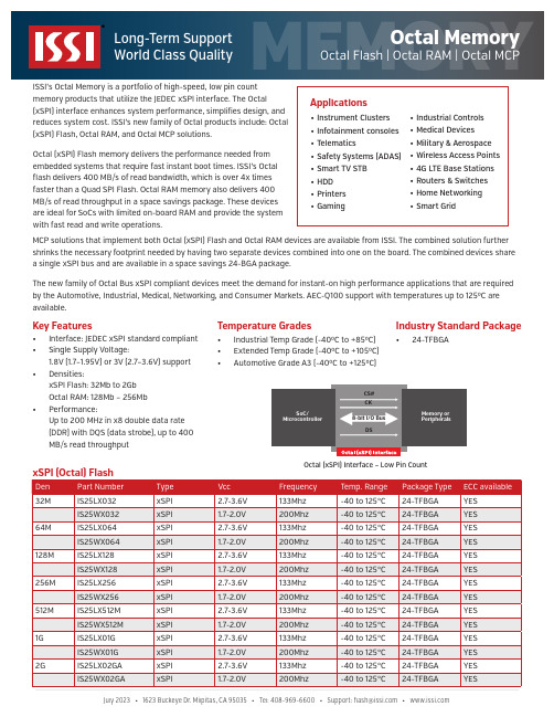
ISSI’s Octal Memory is a portfolio of high-speed, low pin count memory products that utilize the JEDEC xSPI interface. The Octal(xSPI) interface enhances system performance, simplifies design, and reduces system cost. ISSI’s new family of Octal products include: Octal (xSPI) Flash, Octal RAM, and Octal MCP solutions.Octal (xSPI) Flash memory delivers the performance needed from embedded systems that require fast instant boot times. ISSI’s Octal flash delivers 400 MB/s of read bandwidth, which is over 4x times faster than a Quad SPI Flash. Octal RAM memory also delivers 400MB/s of read throughput in a space savings package. These devices are ideal for SoCs with limited on-board RAM and provide the systemwith fast read and write operations.ORYMCP solutions that implement both Octal (xSPI) Flash and Octal RAM devices are available from ISSI. The combined solution further shrinks the necessary footprint needed by having two separate devices combined into one on the board. The combined devices share a single xSPI bus and are available in a space savings 24-BGA package.The new family of Octal Bus xSPI compliant devices meet the demand for instant-on high performance applications that are required by the Automotive, Industrial, Medical, Networking, and Consumer Markets. AEC-Q100 support with temperatures up to 1250C are available.Key Features• Interface: JEDEC xSPI standard compliant • Single Supply Voltage:1.8V (1.7–1.95V) or 3V (2.7–3.6V) support •Densities:xSPI Flash: 32Mb to 2Gb Octal RAM: 128Mb – 256Mb •Performance:Up to 200 MHz in x8 double data rate (DDR) with DQS (data strobe), up to 400 MB/s read throughputIndustry Standard Package•24-TFBGATemperature Grades• Industrial Temp Grade (-400C to +850C)• Extended Temp Grade (-400C to +1050C)•Automotive Grade A3 (-400C to +1250C)Memory or Peripherals8-bit I/O BusCS#CKDSOctal (xSPI) Interface – Low Pin CountJuly2023•pitas,CA95035•Tel:408-969-6600•Support:**************•ORY。
苹果4k高清编辑存储的首选-ARC8050T3-8雷电3代8盘位

东睿8盘位雷电3代磁盘阵列ARC-8050T3-8作为东睿视讯公司新推出的一款雷电接口的存储阵列。
ARC-8050T3-8是一款Thunderblot3接口的存储,他沿用了东睿2代存储的黑色外端同时把雷电接口20Gpb升级为40Gpb速度,大大的提高了阵列的运行的速度与HD 、4k、8k等高清视频的编辑效用。
ARC-8050T3-8做为东睿新出产的8盘位雷电3代存储,采用硬件RAID功能,支持RAID6功能,提高了阵列的安全性,保证了存储数据的安全稳定。
ARC-8050T3-8做为最新雷电3代存储,在这个雷电2代和3代接口的过度阶段,同时支持Thunderbolt3端口向下兼容。
ARC-8050T3-8产品特点。
SPARC T8服务器支持的I O卡列表说明书

Supported IO Cards in SPARC T8 Servers The following table lists I/O cards that are supported in the servers. Some of these cards may have passed their Last Order Date (LOD). For more information, see the Product Manuals.Supported IO Cards for SPARC M8-8 The following table lists I/O cards that are supported in the servers. Some of these cards may have passed their Last Order Date (LOD). For more information, see the Product Manuals.Connect with usCall +1.800.ORACLE1 or visit . Outside North America, find your local office at: /contact. /oracle /oracleCopyright © 2022, Oracle and/or its affiliates. All rights reserved. This document is provided for information purposes only, and the contents hereof are subject to change without notice. This document is not warranted to be error-free, nor subject to any other warranties or conditions, whether expressed orally or implied in law, including implied warranties and conditions of merchantability or fitness for a particular purpose. We specifically disclaim any liability with respect to this document, and no contractual obligations are formed either directly or indirectly by this document. This document may not be reproduced or transmitted in any form or by any means, electronic or mechanical, for any purpose, without our prior written permission.This device has not been authorized as required by the rules of the Federal Communications Commission. This device is not, and may not be, offered for sale or lease, or sold or leased, until authorization is obtained.Oracle and Java are registered trademarks of Oracle and/or its affiliates. Other names may be trademarks of their respective owners.Intel and Intel Xeon are trademarks or registered trademarks of Intel Corporation. All SPARC trademarks are used under license and are trademarks or registered trademarks of SPARC International, Inc. AMD, Opteron, the AMD logo, and the AMD Opteron logo are trademarks or registered trademarks of Advanced Micro Devices. UNIX is a registered trademark of The Open Group. 0120.。
服务器RAID配置方法

使用ARC对ServeRAID 8k-l/8k/8i配置RAID 说明目录第一部分如何配置阵列 (2)初始化硬盘 (4)V OLUME: (6)RAID0: (10)R AID1: (14)如何为阵列添加热备盘H OT-S PARE (17)第二部分其他操作: (21)1.删除阵列 (21)2.恢复阵列 (24)3.如何选择第一引导阵列(选择哪个阵列为第一引导启动阵列): (27)4.重新扫描硬盘 (29)5.安全擦出硬盘和格式化硬盘: (30)6.恢复阵列卡出厂设置 (35)7.查看阵列卡日志 (38)第一部分如何配置阵列开机自检过程中有Ctrl+A提示:按下组合键Ctrl+A进入配置程序。
ARC是内嵌的BIOS的程序,您可以通过它配置ServeRAID-8k-l/8k/8i SAS 控制器.其包括:Array Configuration Utility (ACU) - 创建,配置,管理逻辑驱动器.也可以对驱动器进行初始化及重新扫描.Serial Select - 改变设备及控制器的设置Disk Utilities–格式化或校验媒体设备配置阵列,选择Array Configuration Utility一项回车,出现如下界面:下面文档列举了如何配置V olume,Raid0,Raid1。
其他阵列级别配置方法相同。
第一步:新拆箱的服务器在配置阵列之前先进行初始化。
注:初始化会全清掉您硬盘上的数据和阵列信息,操作时请阅读警告提示。
初始化硬盘1.选择Initialize Drives2.使用“Ins”或空格键把要初始化的硬盘选择到右边的方框中:3.按“Enter”回车键继续下一步4.弹出警告红色框按“Y”键接受提示警告,继续5.开始初始化,等待进程完成:6.完成后自动返回创建阵列总菜单。
第二步:介绍阵列配置方法:Volume:1.初始化硬盘后,选择Create Arrays创建阵列:2. 用Ins选择1块硬盘,回车3.按回车进入阵列配置菜单:4.一块硬盘阵列级别就为“V olume”5.Array Label输入阵列标识(名字任意,符合8.3原则):注Array Label可以不填,但如果配置多个阵列,则后面的阵列必须写。
三大主流品牌SAS RAID卡

RAID控制器市场中的竞争是比较激烈的,很多主流厂商都在不断的推出新品以求能给在这一领域中站稳脚步。
那么,对于消费者来说,如何才能在种类繁多的产品中选择一款正确的产品来为己所用呢?我们先来看看AMCC、Areca、LSI这三家主流厂商推出的三款产品的评测结果吧。
SAS 和SATA磁盘整列,串行标准控制器回顾以往,RAID控制器并不是IT相关讨论中最吸引人的话题。
然而现今,RAID技术已经成为企业中服务器或者工作站上应用的骨干技术,已经面市的RAID控制器产品也在主流应用中给人留下了深刻的印象。
AMCC、Areca、LSI公司的产品和Adaptec、Atto、ICP、Ciprico/Raidcore的产品的比较结果将会为大家奉上。
Adaptec、Atto、ICP、Ciprico/Raidcore的产品4至8端口的SAS或SATA接口RAID控制器被认为是入门级产品,它们的价格通常可以被中小企业接受,并且设计灵活,足够承载中小企业的一般应用。
SAS RAID控制器比只支持SATA接口的产品更为灵活,因为SAS RAID控制器可以连接SAS接口或者SATA 接口硬盘,但是SATA RAID控制器只能连接SATA接口的硬盘驱动器。
因为这个原因,SASRAID控制器被称为是统一标准的串行控制器,它继承了SCSI控制器的一些管理特性,它可以支持高性能的SAS硬盘和高容量的SATA硬盘。
使用串行点对点的SAS或者SATA代替并行SCSI使建立和维护RAID更为便利,SAS 和SATA的电缆比SCSI的68线电缆节约很多,造价更为低廉。
而且SAS和SATA技术克服了传输带宽的瓶颈:并行传输的SCSI总线比如Ultra320 SCSI传输带宽为320MB/s,但是这个带宽被所有驱动器所共享。
虽然SATA300或者SAS传输带宽为300MB/s,但是每个驱动器独享传输带宽。
目前主流存储市场竞争还是很激烈,在存储制造商方面,Adaptec和LSI依旧是最为知名的企业,在存储成为商业中的重点以来这两个厂商就作为业界的存储专家。
ARC-8050
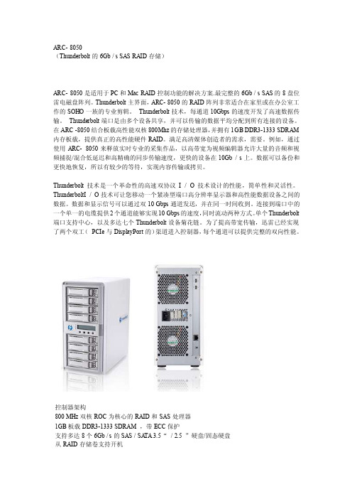
ARC- 8050(Thunderbolt的6Gb / s SAS RAID存储)ARC- 8050是适用于PC和Mac RAID控制功能的解决方案.最完整的6Gb / s SAS的8盘位雷电磁盘阵列。
Thunderbolt主界面,ARC- 8050的RAID阵列非常适合在家里或在办公室工作的SOHO一族的专业剪辑。
Thunderbolt技术,每通道10Gbps的速度开发了高速数据传输。
Thunderbolt端口是由多个设备共享,并可以传输的数据平均分配到所有连接的设备。
在ARC -8050结合板载高性能双核800Mhz的存储处理器,并拥有1GB DDR3-1333 SDRAM 内存板载,提供真正的高性能硬件RAID。
满足高清媒体创造者的需求,需要。
例如,通过使用ARC- 8050来释放实时专业的采集作品,以高带宽为视频编辑器允许大量的音频和视频捕捉/混合低延迟和高精确的同步传输速度,更快的设备在10Gb / s上。
数据可以备份和更快地恢复,所以有较少的等待,实现内容传输或拷贝。
Thunderbolt技术是一个革命性的高速双协议I / O技术设计的性能,简单性和灵活性。
ThunderboltI / O技术可让您移动一个紧凑型端口高分辨率显示器和高性能数据设备之间的数据。
数据和显示信号可以通过双10 Gbps通道发送,并在同一时间收到。
连接到端口中的一个单一的电缆提供2个通道能够实现10 Gbps的速度,同时流动两种方式。
单个Thunderbolt 端口支持中心,以及多达七个Thunderbolt设备菊花链。
为了提高带宽传输,迅雷已经实现了两个双工(PCIe与DisplayPort的)渠道进入控制器,每个通道可以提供完整的双向性能。
控制器架构800 MHz双核ROC为核心的RAID和SAS处理器1GB板载DDR3-1333 SDRAM ,带ECC保护支持多达8个6Gb / s的SAS / SA TA 3.5“/ 2.5 ”硬盘/固态硬盘从RAID存储卷支持开机控制器级别的硬件加密支持对于适配器可用性冗余闪存映像通过LCD,LED和蜂鸣器报警系统状态指示智能电源开/关功能电池备份模块就绪(可选)型号:ARC - 6120BA - T021RAID功能RAID级别0,1,1E ,3,5 ,6,10 ,30,50,60,单个磁盘或JBOD多重RAID选择支持高达1MB的条带大小在线阵列漫游在线RAID级别/条带大小迁移支持全局热备份和本地热备盘即时可用性和后台初始化流畅的数据流高级配置磁盘清理/阵列验证调度的支持多对SSD / HDD硬盘克隆功能SSD的自动监测克隆(AMC )的支持完整的配置管理套件- McRAID经理- 基于浏览器的管理工具(局域网或迅雷)- 按键和液晶显示面板进行设置和状态- 命令行界面(CLI )- 可编写脚本的配置工具- API库支持- 结合GUI用户管理工具- 远程监控支持SNMP- 用于电子邮件通知的SMTP支持功能优势特点1 可启动驱动器支持提供用户通过Thunderbolt在苹果雷电能力下可启动驱动器的能力。
HPE NAS(StoreEasy)存储方案介绍

排名第一的 NAS 产品系列
HPE StoreEasy 是15000 美元以下价格范围内排名第一的 NAS 产品系列;HPE StoreEasy存储系列产品包括:
• StoreEasy 1000存储产品,专为小型企业、分支机构、以及工作群组等环境设计。
• StoreEasy 3000网关存储产品以及HPE StoreEasy 3000网关刀片式存储产品,专为中型到大型企业、以及分支机构存储局域 网等环境设计。
我想要SAN目录下 的SAN.txt文件
SAN优点:
适合数据库存储
SCSI
应用服务器 SAN存储
数据传输处理效率更高
NAS与SAN存储构架
NAS(网络附加存储)
Client Client Client
SAN(存储区域网络)
Client Client Client
LAN
File System
Server
d2000d3000磁盘机箱的单域布线图在单域配置中使用p441控制器的hpestoreeasy1x50p441控制器d2000d3000机箱1d2000d3000机箱2d2000d3000机箱3d2000d3000机箱4从p441控制器到磁盘机箱1模块a的端口2的连接模块a的端口1到磁盘机箱2的端口2的连接模块a的端口1到磁盘机箱3的端口2的连接模块a的端口1到磁盘机箱4的端口2的连接d2000d3000磁盘机箱的单域布线图使用p441控制器的hpestoreeasy1x50使用多个端口p441控制器从p441控制器到组2中磁盘机箱顶部io模块a的端口2的连接个d2000d3000机箱的组1个d2000d3000机箱的组2从p441控制器到组1中磁盘机箱顶部io模块a的端口2的连接中磁盘机箱之间的连接d2000d3000磁盘机箱的双域布线图双域配置最佳容错中使用p441控制器的hpestoreeasy1x50p441控制器从p441控制器到组2中磁盘机箱顶部io模块b的端口2的连接个d2000d3000机箱的组1个d2000d3000机箱的组2从p441控制器到组1中磁盘机箱顶部io模块a的端口2的连接中磁盘机箱之间的连接在d2000d3000磁盘机箱的双域布线图中可以选择具有最佳容错能力戒最优性能的布线方式
东睿ARECA存储苹果驱动安装方法

东睿ARECA存储苹果驱动安装方法说明:本次是在苹果OS X Yosemite 10.11.3操作系统上安装ARECA雷电阵列驱动。
1.此图为ARC磁盘阵列的驱动压缩包MRAID,双击文件解压缩。
2.此图为解压缩后的MRAID安装程序软件,双击安装3.此图为双击安装程序后提示需要安装JAVA,在这可以点击提示上的“更多信息...”自动跳转apple网站链接下载,也可到 东睿视讯网站下载。
(注:因苹果操作系统不同,对应的JAVA程序版本也会不同)4.此图为JAVA的安装包双击打开5.此图为JAVA安装包,双击打开安装JAVA6.此图为JAVA安装界面,根据提示完成安装。
7.此图为安装完JAVA后,双击install_mraid安装软件,提示身份不明,需要修改一下设置。
8.打开(系统偏好设置),点击(安全性与隐私)9.进入安全性与隐私的界面。
10.点击左下角小锁,解锁,在(允许从以下位置下载的应用程序)选择(任何来源),点击确定允许来自任何来源。
11.修改完成后,点击install_mraid安装程序安装。
12.install_mraid安装界面13.点击图中小锁解锁软件,输入用户名密码。
14.此图为,MRAID的安装界面,根据提示完成安装。
(注:安装后,需要重新启动电脑后才可操作)15.安装完成后桌面会生成一个名叫MRAID的文件夹。
16.双击打开MRAID文件夹,里面的内容,双击第二个文件(ArcHTTP64)打开ARC-磁盘阵列的管理控制界面。
17.双击图片上的左侧(+SAS RAID Controlers)选项(+ARC-8050T2 Web managenent)进入ARC-磁盘阵列的管理控制界面。
18.进入ARC-磁盘阵列的管理控制界面之前需要输入名称和密码。
名称:admin 密码:000019.输入完名称和密码后,就进入ARC-磁盘阵列的管理控制界面了。
Thecus N4100PRO 使用说明

使用说明版权和商标公告ndows, Thecus和Thecus产品的其他名字的注册商标为Thecus科技有限公司。
Microsoft, Wi和Windows标志的注册商标为微软公司。
Apple, iTunes和Apple OS X的注册商标为苹果电脑公司。
所有其他商标和品牌名称都是他们各自的所有人的财产。
如未经通知,说明书以改版为准。
版权(C) 2008 Thecus 科技公司。
版权所有关于这份手册这份手册里的所有信息已经很被仔细地核实,以确保它的正确性。
如果发生错误,请给我们反馈。
在未通知的情况下,Thecus科技公司对这份手册内容的修改保留权利。
产品名称: Thecus N4100PRO手册版本: 1.2出厂日期2008年10月有限担保Thecus科技公司担保Thecus N4100PRO的所有部件在他们离开工厂之前都经过全面地测试,还有必须在一般使用的情况下能正常地运作。
一旦发生任何系统故障,如果产品在保修期内,在正常使用的情况下出现故障,Thecus科技公司,当地代表和经销商有责任对客户进行免费保修。
Thecus科技公司不对任何由产品引起的任何数据损坏或损失负责任。
强烈推荐用户进行必要的备份操作。
安全警告对于您的安全方面,请阅读并按照下面的安全警告。
请在安装您的N4100PRO.之前全面地阅读这份手册。
你的N4100PRO是一复杂的电子设备。
不要在任何情况下尝试修理它。
在发生故障的情况下,立即关掉电源,然后到合格的服务中心修理。
对于细节方面联系你的经销商。
不要在电源线上放置任何东西。
不要把电线放在任何可以被踏着走的地方。
谨慎地放好连接电缆,避免他们受到踩踏。
在温度为0°C 和40°C 之间,伴随着20% – 85%的相对湿度,你的N4100PRO可以正常运作。
在极端的环境条件下使用N4100PRO可能会损坏它。
确保给N4100PRO正确地供电(AC 100V ~ 240V, 50/60 Hz,3A). 把N4100PRO插到不正确的电源会被损坏。
Dell PowerVault MD系列存储阵列存储复制适配器(SRA)最佳实践指南说明书

Dell PowerVault MD Series 存储阵列存储复制适配器(SRA)最佳实践指南(客户端)注、小心和警告注: “注”表示可以帮助您更好地使用计算机的重要信息。
小心: “小心”表示可能会损坏硬件或导致数据丢失,并说明如何避免此类问题。
警告: “警告”表示可能会造成财产损失、人身伤害甚至死亡。
版权所有© 2015 Dell Inc. 保留所有权利。
本产品受美国、国际版权和知识产权法律保护。
Dell™和 Dell 徽标是 Dell Inc. 在美国和/或其他司法管辖区的商标。
所有此处提及的其他商标和产品名称可能是其各自所属公司的商标。
2015 - 09Rev. A00目录1 安装和配置 Storage Replication Adapter (SRA) (4)下载 SRA (4)安装过程 (4)受密码保护的存储阵列 (5)NVSRAM 设置 (5)SRA 设备管理服务 (9)更改 SraConfigurationData.xml 中的服务器设置 (9)在 NesSvc.ini 中更改虚拟内存 (10)2 异步远程复制 (11)基于 iSCSI 的远程复制 (11)支持四个远程复制组 (11)10 分钟同步间隔的效果 (11)常规卷建议 (11)命令行选项 (12)Site Recovery Manager 和 ESX/ESXi 中的高级设置 (12)ESX/ESXi 主机设置 (13)3 确定快照存储库大小 (14)快照组存储库 (14)快照卷存储库 (14)SRA 如何使用快照 (15)4 获得帮助 (16)说明文件列表 (16)Dell 说明文件 (16)VMware 说明文件 (16)联系 Dell (16)找到您的系统服务标签 (17)31安装和配置 Storage Replication Adapter (SRA)下载 SRADell MD Series SRA 与 VMware Site Recovery Manager (SRM) 配合使用,以便在分离的 vCenter Server 环境之间进行数据中心故障转移。
铁威马 影视非编直连存储 D8-332存储服务器 说明书
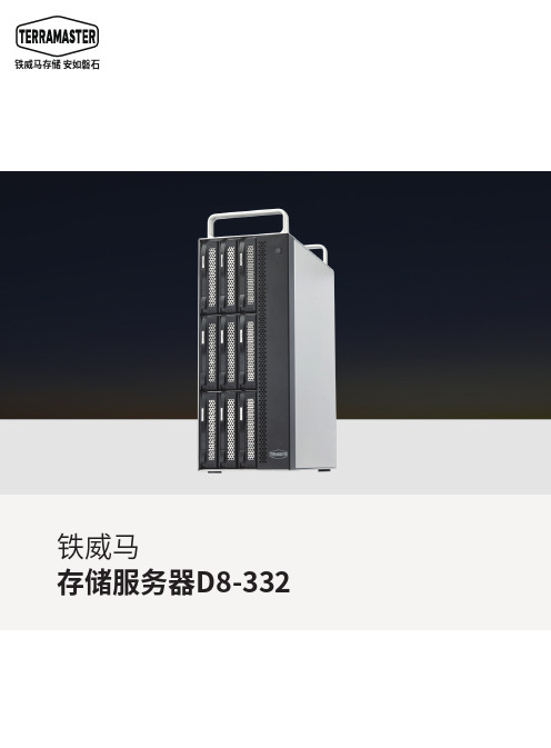
铁威马存储 安如磐石存储服务器D8-332八个盘位,支持3.5寸SATA 硬盘及2.5寸SSD,总存储容量可高达160TB,能让专业人员轻松应对大容量存储需求的挑战。
超大存储容量闪电般的速度!快如闪电般的视频工作流良好的可扩展性D8-332 配备双雷电3(Thunderbolt 3) 40Gbps接口,并采用了硬件 RAID 控制器,在使用7200RPM高速硬盘和RAID 0阵列模式下,实现高达1600 MB/秒的传输速度,同时在RAID 5中实现高达1440MB/秒的速度。
D8-332 的速度可以大大缩短后期制作工作流中几乎所有任务所需的时间。
在很短时间内,从 Blackmagic® 电影摄像机中摄取数小时的原始素材并将其放入 Adobe® Premiere® Pro。
然后编辑 ProRes 422 (HQ)、ProRes 4444 XQ 以及未压缩高清 10 位和 12 位视频的多个数据流。
对于包含了大量高清剪辑的大项目,缩略图和预览渲染的响应会快得多。
Thunderbolt 3 允许您通过单根线缆以菊环链的方式将多达六台设备与计算机相连。
因此您最多可以将六台 D8-332 连接起来,可为您的计算机提供惊人的 超过800TB 容量。
兼容 Thunderbolt 3 和 Thunderbolt 2(仅限 Mac)您在具备 Thunderbolt 3和 Thunderbolt 2 端口的 Mac电脑上,也可以体验 D8-332的快速传输速率。
Apple 的 Thunderbolt 3 (USB-C) 转 Thunderbolt 2 适配器(单独出售)可让 D8-332与采用之前几代 Thunderbolt 技术的 Mac 实现轻松连接。
适用于最严苛的视频专业人员D8-332采用铝制外壳和金属结构,内部采用了3个80mm大型智能温控风扇,完备的散热措施保障了机器随时处于最佳工作状态。
- 1、下载文档前请自行甄别文档内容的完整性,平台不提供额外的编辑、内容补充、找答案等附加服务。
- 2、"仅部分预览"的文档,不可在线预览部分如存在完整性等问题,可反馈申请退款(可完整预览的文档不适用该条件!)。
- 3、如文档侵犯您的权益,请联系客服反馈,我们会尽快为您处理(人工客服工作时间:9:00-18:30)。
ARC-4038ML是一个8托架12Gb / s直接连接存储机箱,可满足PC和Mac 大容量存储需求。
设计并利用Areca现有的高性能外部PCIe RAID适配器,该磁盘塔可配置为RAID级别0,1,1E,3,5,6,10,30,50,60,单磁盘或JBOD,使其成为高性能和容错保护视频数据的理想解决方案。
ARC-4038ML是一个紧凑型磁盘塔,仅使用两个高速SFF-8644连接到系统中安装的HBA或RAID控制器。
高传输速率使ARC-1883X或其他带ARC-4038ML的12Gb / s HBA / RAID 适配器非常适合音频/视频应用,尤其是Mac视频编辑市场快速增长的需求。
ARC-4038ML在其背板上集成了12Gb / s重驱动器芯片。
这可以保证从外部12Gb / s SAS HBA / RAID适配器上的外部连接器到ARC-4038ML无电缆背板连接器的信号,而不会影响性能。
智能冷却通过自动控制冷却风扇的速度,不断适应环境条件。
这种超静音设计,优化了降噪和必要冷却之间的平衡,有助于经销商为视频编辑和数字内容创建提供经济高效的存储解决方案。
无线12Gb / s重驱动器SAS / SATA背板设计,适用于8个可移动驱动器托
ARC-1226-8X RAID卡
型号名称:ARC-1226-8x
I/O处理器:双核RAID-on-Chip 1.2GHz
板载缓存:带ECC的1GB板载DDR3-1600 SDRAM
外置连接:2 x SFF-8644
管理端口:PCIe /带外:BIOS和LCD(可选)和LAN端口
机箱就绪外部串行总线
外形尺寸:(LxH)薄型169.5 x 64.4毫米
适配器架构
双核RAID-on-Chip(ROC)1.2 GHz处理器
PCIe 3.0 x8通道主机接口
带ECC的1GB板载DDR3-1600 SDRAM
直写或回写缓存支持
支持最高8盘位SAS阵列
ARC-1226-8x支持高达8 x 12Gb / s的SAS / SATA硬盘
BIOS启动阵列支持更高的容错能力
uEFI主机BIOS的引导支持
用于RAID事件和事务日志的NVRAM
用于控制器可用性的冗余闪存映像
多适配器支持大容量存储要求
支持基于闪存或备用电池的模块FBM / BBM)准备好(可选)
符合RoHS标准
RAID功能
RAID级别0,1,10(1E),3,5,6,30,50,60,单个磁盘或JBOD
多个RAID选择
支持硬盘固件更新
可配置的条带大小高达1024KB
在线阵列漫游
在线RAID级别/条带大小迁移
在线容量扩展和RAID级别迁移同时
在线成交量增长
SED(自加密驱动器)功能支持
即时可用性和后台初始化
支持全球和专用热备份
自动驱动器插入/移除检测和重建
支持智能电源管理保存能量和延长使用寿命
支持原生4K和512字节扇区SAS和SATA设备
多对SSD / HDD磁盘克隆功能
SSD自动监控克隆(AMC)支持
控制器级硬件加密功能支持
显示器/通知
通过全局HDD指示系统状态
活动/故障连接器,个人活动/故障
连接器,LCD / I2C?连接器和报警蜂鸣器
SMTP支持电子邮件通知
SNMP支持远程管理器
机箱管理(串行总线)准备就绪
RAID管理
闪存ROM中的现场可升级固件
带内经理
通过M / B热键“启动”McBIOS RAID管理器 BIOS
基于Web浏览器的McRAID存储管理器
适用于所有操作系统的ArcHttp代理服务器
支持命令行界面(CLI)
用于客户编写监视器实用程序的API库
单管理员门户(SAP)监视器实用程序
带外管理器(可选)
基于固件嵌入式Web浏览器的McRAID
存储管理器,SMTP管理器,SNMP代理和
通过以太网端口实现Telnet功能
用于客户编写监视器实用程序的API库
支持按钮和LCD显示面板(可选的)
操作系统
Windows 10/8 / Server2012 / 7/2008 / Vista / XP / 2003 Linux的
FreeBSD的
VMware(驱动程序6.x支持带内CLI
管理实用程序
Solaris 10/11 x86 / x86_64
Mac OS X 10.4或更高版本。
