free download Test4pass HP0-D05 pdf exam dumps
proe4.0和5.0安装方法和免费下载
proe4.0和5.0安装方法by 无维网IceFai(黄光辉)不同破解组织所发布的各种proe软件版本,破解的方法实际不尽相同。
本文不同于网络上的其它流水步骤式的安装教程,本教程将详细讲解针对不同的破解组织发布的版本安装过程中可能出现的各种问题和对应的优化处理方法。
同时也对安装过程中的选择对以后的影响做了一一的讲解。
真正让用户在一个教程内解决所有的安装问题。
教程分别使用proe4.0的M060办好和proe5.0的M060版本的安装来讲解,但实际上也适用于proe3.0和proe5.0的安装。
无维网原创,自然与众不同。
准备工作要进行软件的安装,自然需要有安装程序,这可以到无维网proe教程和免费资源中心下载,下载地址如下:proe4.0下载地址:/proe4.htmproe5.0下载地址:/WildFire5.html需要注意的是你要根据你的操作系统来下载对应的版本。
proe有32位操作系统和64位操作系统两个版本(分别用win32和win64标示)。
通常来说winXP是32位的,win7一般是64位的。
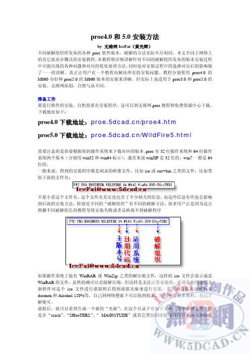
一般来说,得到的安装程序都是刻录的映像文件,比如iso或cue+bin之类的文件,比如类似下面的文件名:不要小看这个文件名,这个文件名其实也包含了不少相关的信息。
而这些信息有些也会影响到后面的安装方法,特别是不同的“破解组织”有不同的破解方法,很多用户正是因为这点照搬不同破解组长的教程导致安装失败或者反映找不到破解程序如果操作系统上装有WinRAR或WinZip之类的解压缩文件,这样的iso文件会显示成是WinRAR的文件,虽然的确可以直接解压缩,但这样是无法正常安装的。
必须是使用虚拟光驱软件对这个iso文件进行虚拟然后得到虚拟光驱来进行安装。
常用的虚拟光驱软件有daemon和Alcohol 120%等,自己到网络搜索下可以找到很多,同时也有很多教程,自己了解便可。
虚拟后,就可以看到生成一个新的“光驱”,在这个目录下有如下文件,其中破解文件一般是在“crack”、“SHooTERS”、“ MAGNiTUDE”或其它类似的比较怪异的目录内(实际是破解组织的名称,比如ZWT、SHooTERS、MAGNiTUDE),很多用户在看到没有crack目录后就会认为软件没有破解文件,实际上现在下载的软件可以说100%都有破解文件的,只是目录不是在crack内而已。
德图400说明书
÷
更换打印纸
纸盒位于打印机的顶部。如图所示装好打印纸。 注:打印纸为热敏打印纸,也就是说只能单面打印。因 此注意正确地安装纸方向 把开关切换到“进行”即可转动纸卷
在接有舒适度探头(0628 0009)的情况下计 算紊流度 该功能键被冻结 在接有 CO 探头情况下,重复校零
- 10 -
Aw 值
NET
温度测量 压力测量 湿度测量 转速测量 风速测量
菜单概览 功能键分配方案
启动测量程序
结束测量程序
在接有温度探头的情况下,利用保存 在 PROBE-T95 fas(t 探头 T95-加速) 中的常数,(也看情况)采用外推法从 读数的变化中得到终值。此功能特别 适于低温探头。常数由电脑软件测得。
参数 温度℃ 湿度%RH 压力 hPa…bar 风速 m/s,m3/h
CO
CO2 转速 电压 V 电流 I WBGT ℃ NET ℃
testo 400 × × × × × × × × × × ×
testo 650 × × × - × × × × × - -
testo 950 × - - - × × × × × - -
德图充电电池
装入电池
打开仪器后盖,把纽扣电池(订货号 0515 0028)装入电池 盒带,“+”符号的一面向上。装入电池或德图充电电池(订 货号 0554 0196)。 注意电池极性!盖上电池盒盖。
参照索引,在“电源”章节进一步了解备选电源、充电模式、 电池质量、充电操作等信息。
纽扣电池-在充电电池耗 尽或更换电池时保存内 存中的数据
伺服电机 说明书
第六章............................................................................................... 61
错误报警及处理 ................................................................................................ 61 6.1 报警一览表 .............................................................................................. 61 6.2 报警处理方法 .......................................................................................... 62
第七章............................................................................................... 65
通电运行 ............................................................................................................ 65 7.1 电源连接 .................................................................................................. 65 7.2 试运行 ...................................................................................................... 67 7.3 调整 .......................................................................................................... 69
Defensicsuzz测试软件说明说明书

Improve software robustness, ensure systems interoperability, and identify vulnerabilities, whether you’re procuring software for business operations or building it.OverviewDefensics® fuzz testing is a comprehensive, powerful, and automated black box solution that enables organizations to effectively and efficiently discover and remediate security weaknesses in software. By taking a systematic and intelligent approach to negative testing, Defensics allows organizations to ensure software security without compromising on product innovation, increasing time to market, or inflating operational costs.Key featuresIntelligent fuzzing engineThe Defensics engine is programmed with knowledge on input type, whether it’s an interface, protocol, or file format. Because the engine has a deep understanding ofthe rules that govern communication within the input type, it can deliver targetedtest cases that exploit that input type’s inherent security weaknesses. This intelligent and systematic approach to fuzz testing allows you to reduce testing time without compromising cost or security.Defensics’ logical user interface walks users through each step of the process, making advanced fuzz testing easy.• Choose from five new vertical solution bundles: automotive, ICS, IoT, networking, andtelecom. Vertical solution bundles include foundational protocols in addition to protocolsrelevant to that vertical market.Fits into most development life cyclesDefensics contains workflows that enable it to fit almost any environment from atechnological and process standpoint. Whether you employ a traditional SDL or a CIdevelopment life cycle, Defensics brings fuzz testing into development early, allowingyou to catch and remediate vulnerabilities more cost-effectively. Got an unconventionaldevelopment life cycle? Our experienced Professional Services team can help you identifyfuzz testing checkpoints, define fuzz testing metrics, and establish a fuzz testing maturityprogram.It’s not just about fitting into the development process; it’s also about working withsurrounding technologies. API and data export capabilities allow Defensics to share data foradditional reporting and analysis, making Defensics a true plug-and-play fuzzer.Detailed, data-rich reports for efficient remediation• Contextualized logs. Remediation logs detail the protocol path and message sequencesbetween Defensics and the system under test (SUT) to help you identify the trigger andtechnical impact of each vulnerability.• Vulnerability mapping. Defensics maps each vulnerability to industry standards such asCWE and injection type to enhance information discovery and expedite remediation.• Issue re-creation. Defensics narrows the vulnerability trigger to a single test case so youcan re-create the issue and verify the fix.• Remediation packages. Generate encrypted remediation packages for your softwaresuppliers to facilitate secure, collaborative remediation across the supply chain.Scale fuzz testing with automationFrom scanning for the test target to determining the number of layers to connect to,Defensics offers a rich set of APIs for flexible, scalable automation to meet all your needs:• Test single devices• Set up repeatable automation to ensure test plans are followed every time• Reduce testing times with the latest in scalable virtualizationDefensics reports contain messagesequence logs to help users identify theroot cause of an anomalous reaction.Defensics offers automated capabilitiesthroughout the testing process, such asDevice Explorer, to relieve users of theburden of manual configuration.Authentication, Authorization, and Accounting (AAA)• Diameter Client/Server • EAPOL Server • Kerberos Server• LDAPv3 Client/Server • RADIUS Client/Server • TACACS+ Client/Server • MACsec ServerApplication• FIX• JSON Format • Web Application• WebSocket Client/Server • XML SOAP Client/Server • XML File • XMPP Server • AMQP Server • WAMP Server • OWAMP Server • TWAMP Server Automotive *• CAN Bus • CAN FD • DoIP Server • gPTP Server • SOME/IP • SRP ServerCellular Core• BICC/M3UA • GRE• GTP Prime • GTPv0• PMIPv6 Client/Server • SCTP Client/Server • SMPP• SMS (SMPP injection)• SMS (file injection)• MAP • BSSAP • BSSAP+• CAP • INAP • ISUP• MTP3 / M2UA|M2PA • TCAP / SCCP / M3UA •SBI Client/ServerDefensics Fuzz Testing | Test Suite CatalogCore IP• DHCP/BOOTP Client/Server • DHCPv6 Client/Server • DNS Client/Server • FTP Client/Server • HTTP Client/Server • HTTP/2 Client/Server • HTTP/3 Server • ICAP Server •IPv4 Package–ARP Client/Server –ICMP –IGMP –IPv4–TCP for IPv4 Client/Server •IPv6 Package –ICMPv6 –IPv6–TCP for IPv6 Client/Server • SOCKS Client/Server • Multicast DNS• PPP over L2TP Client • PPPoEEmail• IMAP4 Client/Server • MIME• POP3 Server•SMTP Client/ServerGeneral Purpose• SDK Express• Universal ASN.1 BER • Universal FuzzerICS *• 60870-5-104 (iec104) Client/Server • 61850/Goose/SV• 61850/MMS Client/Server • BACNET • CIP Server • COAP Server• DNP3 Client/Server • MQTT Client/Server • Modbus Master • Modbus PLC • OPC UA Server • Profinet DCP• Profinet PTCP Client/Server • DLMS/COSEM Client/Server •ISASecure Testing SolutionIoT *• Thread • BT• Wi-Fi AP • gRPC •ZigbeeLink Management• LACP (802.3ad)• STP/RSTP/MSTP/ESTPMedia• Archives Package–GZIP –JAR –ZIP• Audio Package–MP3–MPEG4 (M4A/MP4) –OGG –WAV–Windows Media (WMA/WMV)• Images Package–GIF –JPEG –PNG –TIFF• Video Package–H.264 File Suite –H.264 RTP Format –MPEG2-TS–MPEG4 (M4A/MP4) –OGG–Windows Media (WMA/WMV)Medical• DICOM Server • HL7v2 Server• FHIR Client/ServerMetro Ethernet• BFD• CFM (802.1ag, Y.1731)• E-LMI (MEF-16)• Ethernet (802.3, 802.1Q)• GARP (802.1D)• LLDP (802.1AB)• OAM (802.3ah)• PBB-TE Server•Synchronous Ethernet (ESMC)Networking*• BGP• SNMP• IPv4/IPv6• SIP• Metro EthernetPublic Key Infrastructure (PKI)• CMPv2 Client/Server• CSRRemote Management• CWMP (TR-69) ACS• CWMP (TR-69) CPE• IPMI Server• NETCONF• PCP Server• SNMP trap• SNMPv2c Server• SNMPv3 Server• SSHv1 Server• SSHv2 Server• Syslog• TFTP Server• Telnet ServerRouting• BGP4+ Client/Server• IS-IS• LDP• MPLS Server• MSDP• OSPFv2• OSPFv3• Openflow controller• Openflow switch• PIM-SM/DM• RIP• RIPng• RSVP• TRILL Server• VRRP• COPS Client/Server Telecom*• 5G• SMS• Pre-5GTime Synchronization• IEEE1588 PTP Client/Server• NTP Client/ServerUniversal Plug and Play• UPnP Package–UPnP Multicast Eventing–UPnP SOAP–UPnP SSDP Control Point–UPnP SSDP DeviceVoIP• H.323 Client/Server• H.248 GW Binary/Text• H.248 MGC Binary/Text• MGCP Server• MSRP Server• RTP/RTCP/SRTP• RTSP Client/Server• SIP UAC• SIP UAS (+TT)• SIP-I Server• STUN Client/Server• TURN Client/Server• SigComp ServerVPN• DTLS Client/Server• IKEv2 Client/Server• IPSec• ISAKMP/IKEv1 Client/Server• L2TPv2/v3 Client/Server• OCSP Client/Server• SCEP• SSTP• TLS/SSL Client/Server• X.509v3 Certificates• VXLANWireless• Zigbee Package–FuzzBox Zigbee APS–FuzzBox Zigbee MAC–FuzzBox Zigbee NWK• Thread package–FuzzBox Thread 6LoWPAN–FuzzBox Thread MAC• Bluetooth LE Package–ATT Client/Server–Advertisement–HOGP Host–Health–L2CAP Server–LL Peripheral–Profiles–SMP Client/Server• Bluetooth Package–A2DP–AVRCP–BNEP–HFP AG/Unit–HSP AG/Unit–L2CAP–MAP Client–OBEX-Server–PBAP Client–RFCOMM–SDP• Wi-Fi AP Package–802.11 WLAN AP–802.11 WPA AP–802.11 WPA3 AP• Wi-Fi Client Package–802.11 WLAN Client–802.11 WPA Client–802.11 WPA3 Client5G technology• GTPv2-C Client/Server• S1AP/NAS Client/Server• GTPv1 Client/Server• E1AP Client/Server• NGAP/NAS Client/ServerMonitoring and engine capabilities Instrumentation• Valid case• Syslog• Agent• SNMP• Custom scripting at each testing executionSafeGuard checkers• Amplification• Authentication bypass• Blind LDAP injection• Blind SQL injection• Certificate validation• Compressed signer’s name in RRSIG record • Cross-site request forgery• Cross-site scripting• ECDH Public Key validation• Extra cookie compared to valid case• Heartbleed• Information leakage• Insufficient randomness• LDAP injection in response• Malformed HTTP• Remote execution• SQL injection in response• SMP insecure pairing parameters• Unexpected data• Unprotected credentials• Weak cryptographyAnomaly categories• ASN.1/BER anomalies• Credential anomalies• Deep packet inspection• EICAR antivirus test file• GTUBE (generic test for unsolicited bulkemail)• Control plane injection anomalies• Integer anomalies• Network address anomalies• Overflow anomalies• Underflow anomaliesNote: We add test suites frequently. Pleasecontact us for the latest list.。
富士施乐 ApeosPort DocuCentre 产品系列 打印驱动程序 安装说明书 (Wind
ApeosPort/ DocuCentre 产品系列打印驱动程序安装说明书 (Windows® OS)标准打印机设置和自定义打印机设置是安装打印驱动程序的两种方法。
下面描述了在机器像计算机一样使用 TCP/IP 连接到子网的情况下,如何使用标准打印机设置安装打印驱动程序。
设置流程图:1.[机器] 检查机器的型号名称2.[机器] 检查机器的 IP 地址3.[PC] 下载打印驱动程序4.[PC] 安装打印驱动程序5.[PC] 从计算机发送打印作业注意:您需要使用您的计算机和机器操作。
[PC] 表示计算机操作,[机器] 表示机器操作。
[机器] 检查机器的型号名1.机器的型号名称显示在控制面板的前面。
[机器] 检查机器的 IP 地址1.按<机器确认(计数器确认)>按钮。
2.在 [机器状态/报告输出]屏幕上检查机器的 IP 地址。
重要说明:如果指定了 IPv6 地址,则不会显示 IPv4 地址。
在系统管理员模式,选择 [规格设定] > [网络设定] > [协议设置] > [TCP/IP - 网络设置],然后选择[确认/变更]。
请参阅 [IPv4 - IP 地址]。
3.选择[关闭]。
[PC] 下载打印驱动程序您可以通过以下两种方法中的任何一种方法获取打印驱动程序。
•从随机器一起提供的软件/ 产品手册中安装•从我们的官方网站下载。
()[PC] 安装打印驱动程序标准打印机设置和自定义打印机设置是安装打印驱动程序的两种方法。
下面描述了在机器像计算机一样使用 TCP/IP 连接到子网的情况下,如何使用标准打印机设置安装下载的PCL 打印驱动程序。
1.双击下载的 PCL 打印驱动程序。
2.确认软件许可协议,并单击[是]。
3.单击[开始安装]。
注意:如果出现如下‘User Account Control’对话框,选择[Yes]。
4.选择[自定义],并单击[下一步]。
5.选择[本地打印机],并单击[下一步]。
free download Test4pass COG-105 pdf exam dumps
Exam:IBM COG-105Title:IBM Cognos8BI TechnicalSpecialistVersion:Demo1.Which of the following is true when Cognos8gateway receives a request?A.Requests are passed directly to the Cognos content manager.B.A connection is created to the database server.C.The requests are directed to Access Manager.D.Passwords are encrypted to ensure security.Answer:D2.Which of the following is true about Cognos8dispatchers?A.Requests can be routed to specific dispatchers based on packages or user group requirements.B.Each Java Virtual Machine(JVM)can have multiple dispatchers.C.The administrator must register a new dispatcher manually.D.Dispatchers cannot be managed as part of a folder set.Answer:A3.What is a portlet?A.The routing subsection of a listener port.B.A mechanism for displaying web content as part of a portal page.C.A credential that is stored on the Web server.D.A credential that is stored for the session only.Answer:B4.What is true about the Cognos gateway?A.It can reside on multiple web servers in a single environment.B.Improbability Drive Algorithms(IDA)are used to detect intrusions.C.ISAPI is the default gateway.D.It must be installed on the user's desktop.Answer:A5.What communication protocol is used between the Web Server and the Cognos8dispatcher?A.SOAPB.XMLC.HTTPD.XSLTAnswer:C6.Which Cognos8Service runs outside the servlet container?A.Job ServiceB.Delivery ServiceC.Data IntegrationD.Report ServiceAnswer:D7.Which Cognos8Service makes external JNI calls?A.Content ManagerB.Web gatewayC.Bootstrap ServiceD.Presentation ServiceAnswer:A。
findInFiles 0.4.0 软件说明说明书

Package‘findInFiles’October13,2022Type PackageTitle Find Pattern in FilesVersion0.4.0Description Creates a HTML widget which displays the results of searching for a pat-tern infiles in a given folder.The results can be viewed in the'RStudio'viewer pane,in-cluded in a'R Markdown'document or in a'Shiny'app.Also provides a'Shiny'application al-lowing to run the widget and to navigate in the results.License GPL-3Encoding UTF-8SystemRequirements grepImports htmlwidgets,stringr,crayon,vctrs,tibble,stringi,shinySuggests shinyAce,shinyWidgets,shinyjqui,shinyFiles,shinyvalidate,fsURL https:///stla/findInFilesBugReports https:///stla/findInFiles/issuesRoxygenNote7.1.2NeedsCompilation noAuthor Stéphane Laurent[aut,cre],Rob Burns[ctb,cph]('ansi-to-html'library)Maintainer Stéphane Laurent<***********************>Repository CRANDate/Publication2022-04-1113:02:29UTCR topics documented:FIF2dataframe (2)FIF2tibble (2)findInFiles (3)findInFiles-shiny (4)shinyFIF (6)Index712FIF2tibble FIF2dataframe Output of‘findInFiles‘as a dataframeDescriptionReturns the results of findInFiles in a dataframe,when the option output="viewer+tibble"or output="tibble"is used.UsageFIF2dataframe(fif)Argumentsfif the output of findInFiles used with the option output="viewer+tibble"or output="tibble"ValueThe results of findInFiles in a dataframe.Examplesfolder<-system.file("example",package="findInFiles")fif<-findInFiles("R","function",root=folder,output="viewer+tibble")FIF2dataframe(fif)fifFIF2tibble Output of‘findInFiles‘as a tibbleDescriptionReturns the results of findInFiles in a tibble,when the option output="viewer+tibble"is used.UsageFIF2tibble(fif)Argumentsfif the output of findInFiles used with the option output="viewer+tibble"ValueThe results of findInFiles in a tibble.findInFiles3Examplesfolder<-system.file("example",package="findInFiles")fif<-findInFiles("R","function",root=folder,output="viewer+tibble")FIF2tibble(fif)fiffindInFiles Find pattern infilesDescriptionFind a pattern in somefiles.UsagefindInFiles(ext,pattern,depth=NULL,wholeWord=FALSE,ignoreCase=FALSE,perl=FALSE,excludePattern=NULL,excludeFoldersPattern=NULL,root=".",output="viewer")Argumentsextfile extension,e.g."R"or"js"pattern pattern to search for,a regular expression,e.g."function"or"^function"depth depth of the search,NULL or a negative number for an entire recursive search (subdirectories,subdirectories of subdirectories,etc.),otherwise a positive inte-ger:0to search in the root directory only,1to search in the root directory andits subdirectories,etc.wholeWord logical,whether to match the whole patternignoreCase logical,whether to ignore the caseperl logical,whether pattern is a Perl regular expressionexcludePattern a pattern;exclude from search thefiles and folders which match this pattern excludeFoldersPatterna pattern;exclude from search the folders which match this patternroot path to the root directory to search fromoutput one of"viewer","tibble"or"viewer+tibble";see examplesValueA tibble if output="tibble",otherwise a htmlwidget object.Exampleslibrary(findInFiles)folder<-system.file("example",package="findInFiles")findInFiles("R","function",root=folder)findInFiles("R","function",root=folder,output="tibble")fif<-findInFiles("R","function",root=folder,output="viewer+tibble")FIF2tibble(fif)FIF2dataframe(fif)fiffolder<-system.file("www","shared",package="shiny")findInFiles("css","outline",excludePattern="*.min.css",root=folder) findInFiles-shiny Shiny bindings for findInFilesDescriptionOutput and render functions for using findInFiles within Shiny applications and interactive Rmd documents.UsageFIFOutput(outputId,width="100%",height="400px")renderFIF(expr,env=parent.frame(),quoted=FALSE)ArgumentsoutputId output variable to read fromwidth,height a valid CSS unit(like"100%","400px","auto")or a number,which will be coerced to a string and have"px"appendedexpr an expression that generates a’findInFiles’widgetenv the environment in which to evaluate exprquoted logical,whether expr is a quoted expression(with quote())ValueFIFOutput returns an output element that can be included in a Shiny UI definition,and renderFIF returns a shiny.render.function object that can be included in a Shiny server definition.Exampleslibrary(findInFiles)library(shiny)onKeyDown<-HTML(function onKeyDown(event){ ,var key=event.which||event.keyCode; ,if(key===13){ ,Shiny.setInputValue( ,"pattern",event.target.value,{priority:"event"} , ); ,} ,})ui<-fluidPage(tags$head(tags$script(onKeyDown)),br(),sidebarLayout(sidebarPanel(selectInput("ext","Extension",choices=c("R","js","css")),tags$div(class="form-group shiny-input-container",tags$label(class="control-label","Pattern"),tags$input(type="text",class="form-control",onkeydown="onKeyDown(event);",placeholder="Press Enter when ready")),numericInput("depth","Depth(set-1for unlimited depth)",value=0,min=-1,step=1),checkboxInput("wholeWord","Whole word"),checkboxInput("ignoreCase","Ignore case")),mainPanel(FIFOutput("results")))6shinyFIF )server<-function(input,output){output[["results"]]<-renderFIF({req(input[["pattern"]])findInFiles(ext=isolate(input[["ext"]]),pattern=input[["pattern"]],depth=isolate(input[["depth"]]),wholeWord=isolate(input[["wholeWord"]]),ignoreCase=isolate(input[["ignoreCase"]]))})}if(interactive()){shinyApp(ui,server)}shinyFIF Shiny application’Find infiles’DescriptionLaunches a Shiny application allowing to run findInFiles and to navigate in the results.UsageshinyFIF()ValueNo returned value,just launches the Shiny application.NoteThe packages listed in the Suggestsfield of the package description are required.IndexFIF2dataframe,2FIF2tibble,2FIFOutput(findInFiles-shiny),4 findInFiles,2,3,4,6findInFiles-shiny,4renderFIF(findInFiles-shiny),4 shinyFIF,67。
unix课后习题
第1章操作系统概述1、什么是操作系统?答:控制其他程序运行,管理系统资源并为用户提供操作界面的系统软件的集合。
2、操作系统有哪三种类型,他们之间有什么区别?答:单用户单进程、单用户多进程、多用户多进程。
第一个是操作系统在同一时间允许一个用户,同一时间只能运行一个进程。
3、对分时系统,给出一个清晰而准确的描述?答:多个用户分享使用一台JSJ,多个程序分时共享硬件和软件资源。
多路性、独占性、交互性和与时性。
4、目前典型操作系统的主要功能是什么?这些功能的基本用途是什么?答:功能,执行程序,程序的输入和输出操作进程间的通信,错误检测与报告,不同类型的文件操作,用户和安全管理。
5、分别列出字符用户界面和图形用户界面的一个优点和一个缺点?答:CUI执行效率高,外观不美观;GUI 便于使用,缺乏可扩展性。
6、分别列出字符用户界面和图形用户界面有什么不同?目前,在UNIX系统中最流行的图形用户界面是什么?它是由谁开发的?答:CUI通过输入命令来完成相关操作,GUI通过输入设备(如鼠标)来完成相关操作。
7、应用程序程序员接口(API)和应用程序用户接口(AUI)分别包括那些内容?答:AUI通过语言库和系统调用接口与操作系统内核联系在一起,应用软件构成了AUI,系统调用接口由一组为完成特定任务而执行内核代码的函数构成,语言库和系统调用接口构成API。
8、列出UNIX家族中常见的5种操作系统。
你现在使用的是哪一个UNIX系统?答:UNIX版本:AIX、BSD、FreeBSD、LINUX、system V。
第2章UNIX操作系统简史2、如果由你来设计POSIX标准,将包含那些内容?答:支持程序和命令互相兼容,易用性。
3、UNIX系统的前身是什么?UNIX与其前身最初在哪里,由谁开发的?答:前身是MULTICS,由Dennis Ritchie 和Ken Thompson在AT&T中研制。
第3章UNIX起步1、主存的作用是什么?答:主存用来存储正在运行的程序或进程。
test--pdf

01封装隔绝了使用者和电工,外部使用时只需提供必要的功能而无需考虑其实现P A R T O N E 1.2为了避免后期代码的变化导致工程量的增加,首先要做的是将会变化的代码变成一个大的框架,给它们一个统一的类型,也就是统一继承三大特征-----继承01继承P A R T O N E 1.3一个相同的方法有不同的实现功能的方法,每个子类都有自己独特的个性和功能,但它们在一定程度上具有相同的特征,即该方法可根据调用者调用该方法而采取不同的实现方法,提高了代码的灵活性,降低了类与类之间的耦合度,使得代码整体架构更加清晰,并且拓展性更高。
继承是多态的体现,而多态则使其在类与类之间的切换变得更加灵活,有效的降低了其相互之间的耦合性。
三大特征-----多态01贼low的例子封装继承多态只负责通电02每个类只负责一个功能,避免导致某个功能修改的原因导致需要修改的类的原因导致拥有多个功能的类其他功能发生故障,进而导致整个程序出现错误,因此,我们应尽可能遵循类的功能单一,即单一原则,以保证修改该功能不会因此而影响其他功能的正常运转。
六大原则---单一原则多种都有充电插头02用组合的方式建立了类与组合的类之间的关系,它是一种‘有’的关系,比如手机充电器有插头,手机充电器有安卓数据线,手机充电器有iPhone 数据线,手机充电器有Type-c 数据线,手机充电器有.......六大原则---组合复用原则02六大原则---依赖倒置从对象的调用角度:从人的角度看,应直接调用具体的实现子类,但此做法会导致调用切换对象时的不灵活。
从代码的角度看,应尽量调用抽象类而不是子类,子类依赖于抽象类,而抽象类是稳定的,子类则是随时可能变化的。
多种都有充电插头02对修改关闭,对扩展开放,即功能的拓展不应修改原有的代码,而是单独重新创建一个类,以保证代码的功能稳定性,正因如此,需要保证抽象层足够稳定,避免导致因功能需求的变更而导致抽象层的修改,进而造成大面积的影响。
HP ProDesk 405 G4 SFF BIOS 简单模拟器指南说明书
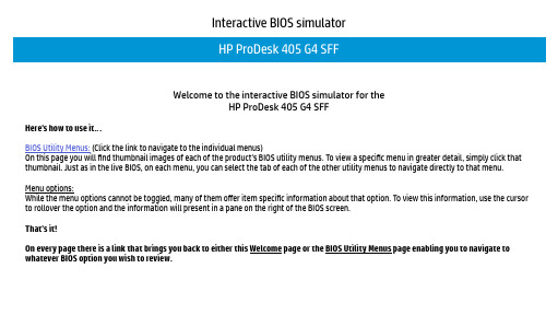
Interactive BIOS simulatorWelcome to the interactive BIOS simulator for theHP ProDesk 405 G4 SFFHere’s how to use it…BIOS Utility Menus: (Click the link to navigate to the individual menus)On this page you will find thumbnail images of each of the product’s BIOS utility menus. To view a specific menu in greater detail, simply click that thumbnail. Just as in the live BIOS, on each menu, you can select the tab of each of the other utility menus to navigate directly to that menu. Menu options:While the menu options cannot be toggled, many of them offer item specific information about that option. To view this information, use the cursor to rollover the option and the information will present in a pane on the right of the BIOS screen.That’s it!On every page there is a link that brings you back to either this Welcome page or the BIOS Utility Menus page enabling you to navigate to whatever BIOS option you wish to review.BIOS Utility MenusBack to Welcome PageMain Security System Configuration ExitBoot OptionsMain MenuBack to BIOS Utility MenusMain Security Configuration Boot Options ExitItem Specific HelpSystem Time System Date Product Name System Family Product Number System Board ID Born On Date Processor Type Total Memory BIOS Vendor BIOS Revision Device Firmware Revision Serial Number UUID Number System Board CT Number Factory installed OS System Log Build ID Feature Byte [05:16:51][10/20/2018]HP Slim Desktop PC HP Desktop 4NS06AV 852600/00/0000AMD PRO A6-9500 R5, COMPUTE 2C+6G 8 GB AMI B.09HSHW310106 6867D2A5-D90A-A135-35BB-8FE3F8DB0F40PHMMCX3CYB6B29Win1018WW2HIT6a#SABG#DABG 2U3E 3K3N 4C6J 6S6b 7B7K 7P7Q 7T7W aBaJ apaq asau bCbh bpcb dUdp dqfP js .8eSecurity MenuBack to BIOS Utility MenusMain Security Configuration Boot Options ExitItem Specific HelpAdministrator Password [Clear]Power-On Password [Clear]Intel Software Guard Extensions (SGX) [Enabled]TPM Device [Available]TPM State [Enable]Clear TPM [No]Restore Security settings to Factory defaultsSystem Configuration MenuBack to BIOS Utility MenusMain Security Configuration Boot Options ExitItem Specific HelpLanguage [English]Virtualization Technology [Disabled]Num Lock State at Power-On [On]S4/S5 Wake on LAN [Disabled]Device OptionsThermalUEFI HII ConfigurationBoot Options MenuBack to BIOS Utility MenusMain Security Configuration Boot Options ExitItem Specific HelpPOST HotKey Delay [0]USB Boot [Enabled]Network Boot [Disabled]Network Boot Protocol [IPv4+IPv6 (UEFI]Legacy Support [Disabled]Secure Boot [Disabled]Platform Key EnrolledPending Action NoneClear All Secure Boot KeysLoad HP Factory Defaults KeysLoad MSFT Debug Policy KeysUEFI Boot OrderOS Boot ManagerInternal CD/ROM DriveUSB Flash Drives/USB Hard DiskUSB CD/DVD ROM Drive!Network AdapterLegacy Boot OrderNotebook Hard DriveUSB Flash Drive/USB Hard DiskUSB CD/DVD ROM Drive!Network AdapterExit MenuBack to BIOS Utility MenusMain Security Configuration Boot Options ExitItem Specific HelpSave Changes and ExitIgnore Changes and ExitLoad Setup DefaultsDevice Firmware RevisionBack to BIOS Utility MenusMainItem Specific HelpDevice Firmware RevisionIntel ME (Management Engine) 12.0.6.1120GOP (Graphic Output Protocol) 9.0.1079System LogBack to BIOS Utility MenusMainItem Specific HelpSystem LogResult Time:0502 010109-000039- No Data -- No Data -- No Data -- No Data -- No Data -- No Data -- No Data -- No Data -- No Data -- No Data -- No Data -Device OptionsBack to BIOS Utility MenusConfigurationItem Specific HelpDevice OptionsSerial Port [3F8-3FF; IRQ4]ThermalBack to BIOS Utility MenusConfigurationItem Specific HelpThermalCPU Fan Speed : N/AUEFI HII ConfigurationBack to BIOS Utility MenusConfigurationItem Specific HelpUEFI HII ConfigurationRealtek PCIe GBE Controller (MAC: 10:E7:C6: 29:62:00 )。
LT6604IUFF-15#PBF,LT6604CUFF-15#PBF,LT6604CUFF-15#TRPBF,LT6604IUFF-15#TRPBF, 规格书,Datasheet 资料

T YPICAL APPLICATIOND ESCRIPTION Differential Amplifi er and15MHz Lowpass FilterThe LT ®6604-15 consists of two matched, fully differential amplifi ers, each with a 4th order, 15MHz lowpass fi lter. The fi xed frequency lowpass fi lter approximates a Chebyshev response. By integrating a fi lter and a differential ampli-fi er, distortion and noise are made exceptionally low. At unity gain, the measured in band signal-to-noise ratio is an impressive 76dB. At higher gains, the input referred noise decreases, allowing the part to process smaller input differential signals without signifi cantly degrading the signal-to-noise ratio.Gain and phase are highly matched between the two chan-nels. Gain for each channel is independently programmed using two external resistors. The LT6604-15 enables level shifting by providing an adjustable output common mode voltage, making it ideal for directly interfacing to ADCs.The LT6604-15 is fully specifi ed for 3V operation. The differential design enables outstanding performance at a 2V P-P signal level for a single 3V supply. See the back page of this datasheet for a complete list of related single and dual differential amplifi ers with integrated 2.5MHz to 20MHz lowpass fi lters.Channel to Channel Gain MatchingF EATURESA PPLICATIONS nDual Differential Amplifi er with 15MHz Lowpass Filters 4th Order Filters Approximates Chebyshev Response Guaranteed Phase and Gain Matching Resistor-Programmable Differential Gain n 76dB Signal-to-Noise (3V Supply, 2V P-P Output)n Low Distortion, 2V P-P , 800Ω Load, V S = 3V 1MHz: 86dBc 2nd, 90dBc 3rd 10MHz: 63dBc 2nd, 69dBc 3rd n Specifi ed for Operation with 3V , 5V and ±5V Supplies n Fully Differential Inputs and Outputsn Adjustable Output Common Mode Voltage n Small 4mm × 7mm × 0.75mm QFN PackagenDual Differential ADC Driver Plus Filter n Single-Ended to Differential Converter n Matched, Dual, Differential Filter Stagen Common Mode T ranslation of Differential Signals nHigh Speed ADC Antialiasing and DAC Smoothing in Wireless Infrastructure or Networking Applications n High Speed Test and Measurement Equipment n Medical ImagingL , L T , L TC and L TM are registered trademarks of Linear Technology Corporation. All other trademarks are the property of their respective owners.+––0.2512160.15660415 TA01b841014620–0.2–0.1–0.150.05–0.050.10.200.25GAIN MATCH (dB)LT6604-15P IN CONFIGURATIONA BSOLUTE MAXIMUM RATINGS Total Supply Voltage .................................................11V Operating Temperature Range (Note 6)....–40°C to 85°C Specifi ed Temperature Range (Note 7) ....–40°C to 85°C Junction Temperature ...........................................150°C Storage Temperature Range ...................–65°C to 150°C Input Current+IN, –IN, V OCM , V MID (Note 8) .........................±10mA Lead Temperature (Soldering, 10 sec) ..................300°CPARAMETERCONDITIONSMIN TYP MAX UNITS Filter Gain Either Channel, V S = 3VV IN = 2V P-P , f IN = DC to 260kHzV IN = 2V P-P , f IN =1.5MHz (Gain Relative to 260kHz)V IN = 2V P-P , f IN = 7.5MHz (Gain Relative to 260kHz)V IN = 2V P-P , f IN = 12MHz (Gain Relative to 260kHz)V IN = 2V P-P , f IN = 15MHz (Gain Relative to 260kHz)V IN = 2V P-P , f IN = 45MHz (Gain Relative to 260kHz)V IN = 2V P-P , f IN = 75MHz (Gain Relative to 260kHz)l l l l l l–0.5–0.1–0.3–0.3–0.70.1000.20–29–460.50.10.41.01.0–25dB dB dB dB dB dB dBORDER INFORMATIONLEAD FREE FINISH TAPE AND REEL PART MARKING*PACKAGE DESCRIPTIONSPECIFIED TEMPERATURE RANGE L T6604CUFF-15#PBF L T6604CUFF-15#TRPBF 6041534-Lead (4mm × 7mm) Plastic QFN 0°C to 70°C L T6604IUFF-15#PBFL T6604IUFF-15#TRPBF6041534-Lead (4mm × 7mm) Plastic QFN–40°C to 85°CConsult L TC Marketing for parts specifi ed with wider operating temperature ranges. *The temperature grade is identifi ed by a label on the shipping container.Consult L TC Marketing for information on non-standard lead based fi nish parts.For more information on lead free part marking, go to: http://www.linear .com/leadfree/ For more information on tape and reel specifi cations, go to: http://www.linear .com/tapeandreel/E LECTRICAL CHARACTERISTICS The l denotes specifi cations that apply over the full operating temperaturerange, otherwise specifi cations are at T A = 25°C. Unless otherwise specifi ed V S = 5V (V + = 5V , V –= 0V), R IN = 536Ω, and R LOAD = 1k.31 V –32 V –33 N C34 V M I D AV +B 17N C 16N C 15V O C M B 1430 NC 29 –OUTA 28 NC 27 +OUTA 26 NC 25 V +A 24 V –23 NC 22 NC 21 –OUTB 20 NC 19 +OUTB 18 NCNC 1+INA 2NC 3–INA 4NC 5V OCMA 6V – 7V MIDB 8NC 9+INB 10NC 11–INB 12NC 13TOP VIEW UFF PACKAGE34-LEAD (4mm × 7mm) PLASTIC QFN35T JMAX = 150°C, θJA = 34°C/W , θJC = 2.7°C/WEXPOSED PAD (PIN 35) IS V –, MUST BE SOLDERED TO PCB(Note 1)LT6604-15 E LECTRICAL CHARACTERISTICSThel denotes specifi cations that apply over the full operating temperature range, otherwise specifi cations are at T A = 25°C. Unless otherwise specifi ed V S = 5V (V+ = 5V, V– = 0V), R IN = 536Ω, and R LOAD = 1k.PARAMETER CONDITIONS MIN TYP MAX UNITSMatching of Filter Gain, V S = 3V V IN = 2V P-P, f IN = DC to 260kHzV IN = 2V P-P, f IN = 1.5MHz (Gain Relative to 260kHz)V IN = 2V P-P, f IN = 7.5MHz (Gain Relative to 260kHz)V IN = 2V P-P, f IN = 12MHz (Gain Relative to 260kHz)V IN = 2V P-P, f IN = 15MHz (Gain Relative to 260kHz)V IN = 2V P-P, f IN = 45MHz (Gain Relative to 260kHz)V IN = 2V P-P, f IN = 75MHz (Gain Relative to 260kHz)llllll0.050.010.020.030.060.130.150.50.10.30.40.61.52.8dBdBdBdBdBdBdBMatching of Filter Phase, V S = 3V V IN = 2V P-P, f IN = 1.5MHzV IN = 2V P-P, f IN = 7.5MHzV IN = 2V P-P, f IN = 12MHz lll0.60.80.9134degdegdegFilter Gain Either Channel, V S = 5V V IN = 2V P-P, f IN = DC to 260kHzV IN = 2V P-P, f IN =1.5MHz (Gain Relative to 260kHz)V IN = 2V P-P, f IN = 7.5MHz (Gain Relative to 260kHz)V IN = 2V P-P, f IN = 12MHz (Gain Relative to 260kHz)V IN = 2V P-P, f IN = 15MHz (Gain Relative to 260kHz)V IN = 2V P-P, f IN = 45MHz (Gain Relative to 260kHz)V IN = 2V P-P, f IN = 75MHz (Gain Relative to 260kHz)llllll–0.5–0.1–0.4–0.4–0.80.1–29–460.50.10.30.90.9–25dBdBdBdBdBdBdBMatching of Filter Gain, V S = 5V V IN = 2V P-P, f IN = DC to 260kHzV IN = 2V P-P, f IN =1.5MHz (Gain Relative to 260kHz)V IN = 2V P-P, f IN = 7.5MHz (Gain Relative to 260kHz)V IN = 2V P-P, f IN = 12MHz (Gain Relative to 260kHz)V IN = 2V P-P, f IN = 15MHz (Gain Relative to 260kHz)V IN = 2V P-P, f IN = 45MHz (Gain Relative to 260kHz)V IN = 2V P-P, f IN = 75MHz (Gain Relative to 260kHz)llllll0.050.010.020.030.060.130.150.50.10.30.40.61.52.8dBdBdBdBdBdBdBMatching of Filter Phase, V S = 5V V IN = 2V P-P, f IN = 1.5MHzV IN = 2V P-P, f IN = 7.5MHzV IN = 2V P-P, f IN = 12MHz lll0.60.80.9134degdegdegFilter Gain Either Channel, V S = ±5V V IN = 2V P-P, f IN = DC to 260kHz–0.6–0.10.4dBFilter Gain, R IN = 133ΩV IN = 0.5V P-P, f IN = DC to 260kHz V S = 3VV S = 5VV S = ±5V 11.511.511.412.012.011.912.512.512.4dBdBdBFilter Gain Temperature Coeffi cient (Note 2)f IN = 250kHz, V IN = 2V P-P780ppm/°C Noise Noise BW = 10kHz to 15MHz, R IN = 536Ω109μV RMSDistortion (Note 4)1MHz, 2V P-P, R L = 800Ω, V S = 3V 2nd Harmonic3rd Harmonic 8690dBcdBc10MHz, 2V P-P, R L = 800Ω, V S = 3V 2nd Harmonic3rd Harmonic 6369dBcdBcChannel Separation (Note 9)1MHz, 2V P-P, R L = 800Ω–117dB10MHz, 2V P-P, R L = 800Ω–102dBDifferential Output Swing Measured Between +OUT and –OUT, V OCM shorted to V MIDV S = 5VV S = 3V ll3.803.754.754.50V P-P_DIFFV P-P_DIFFInput Bias Current Average of IN+ and IN–l–90–35μAInput Referred Differential Offset R IN = 536Ω V S = 3VV S = 5VV S = ±5V lll51010253035mVmVmVR IN = 133Ω V S = 3VV S = 5VV S = ±5V lll555151720mVmVmVLT6604-15PARAMETER CONDITIONSMIN TYP MAX UNITS Differential Offset Drift10μV/°CInput Common Mode Voltage (Note 3)Differential Input = 500mV P-P, R IN = 133ΩV S = 3V V S = 5V V S = ±5Vl l l00–2.51.531V V VOutput Common Mode Voltage (Note 5)Differential Output = 2V P-P, V MID = Open, Common Mode Voltage at V OCM V S = 3V V S = 5V V S = ±5V l l l 11.5–1 1.532V V V Output Common Mode Offset (with Respect to V OCM )V S = 3V V S = 5V V S = ±5V l l l –35–40–5555–10404035mV mV mV Common Mode Rejection Ratio 64dB Voltage at V MID V S = 3V V S = 5Vl 2.45 2.501.5 2.56V V V MID Input Resistance l 4.3 5.77.7kΩV OCM Bias CurrentV OCM = V MID = V S /2 V S = 3VV S = 5V l l –10–10–2–2μA μAPower Supply Current (per Channel)V S = 3V, V S = 5V V S = 3V V S = 5V V S = ±5Vl l l 35343839444548mA mA mA mA Power Supply Voltagel311VE LECTRICAL CHARACTERISTICS The l denotes specifi cations that apply over the full operating temperaturerange, otherwise specifi cations are at T A = 25°C. Unless otherwise specified V S = 5V (V + = 5V , V –= 0V), R IN = 536Ω, and R LOAD = 1k.Note 1: Stresses beyond those listed under Absolute Maximum Ratings may cause permanent damage to the device. Exposure to any Absolute Maximum Rating condition for extended periods may affect device reliability and lifetime.Note 2: This is the temperature coeffi cient of the internal feedback resistors assuming a temperature independent external resistor (R IN ).Note 3: The input common mode voltage is the average of the voltagesapplied to the external resistors (R IN ). Specification guaranteed for R IN ≥ 100Ω.Note 4: Distortion is measured differentially using a differential stimulus. The input common mode voltage, the voltage at V OCM , and the voltage at V MID are equal to one half of the total power supply voltage.Note 5: Output common mode voltage is the average of the +OUT and –OUT voltages. The output common mode voltage is equal to V OCM .Note 6: The L T6604C-15 is guaranteed functional over the operating temperature range –40°C to 85°C.Note 7: The L T6604C-15 is guaranteed to meet 0°C to 70°C specifi cations and is designed, characterized and expected to meet the extendedtemperature limits, but is not tested at –40°C and 85°C. The L T6604I-15 is guaranteed to meet specifi ed performance from –40°C to 85°C.Note 8: Input pins (+IN, –IN, V OCM and V MID ) are protected by steering diodes to either supply. If the inputs should exceed either supply voltage, the input current should be limited to less than 10mA. In addition, the inputs +IN, –IN are protected by a pair of back-to-back diodes. If the differential input voltage exceeds 1.4V , the input current should be limited to less than 10mA.Note 9: Channel separation (the inverse of crosstalk) is measured by driving a signal into one input, while terminating the other input. Channel separation is the ratio of the resulting output signal at the driven channel to the output at the channel that is not driven.LT6604-15T YPICAL PERFORMANCE CHARACTERISTICS Output ImpedanceCommon Mode Rejection RatioPower Supply Rejection RatioDistortion vs FrequencyDistortion vs Signal LevelAmplitude ResponsePassband Gain and PhasePassband Gain and DelayFREQUENCY (MHz)0.1–20G A I N (d B )–10010110100660415 G01–30–40–50–60FREQUENCY (MHz)G A I N (d B )PHASE (DEG)–3–1120660415 G02–5–7–4–20–6–8–945135225–45–135090180–90–180–2255101525FREQUENCY (MHz)G A I N (d B )DELAY (ns)6101420660415 G042–248120–4–630405*********4515505101525FREQUENCY (MHz)1O U T P U T I M P E D A N C E (Ω)100.110100660415 G050.11100FREQUENCY (MHz)0.1C M R R (d B )607080110100660415 G065040306575554535FREQUENCY (MHz)0.150P S R R (d B )607080110100660415 G07403020100FREQUENCY (MHz)0.1–100–110D I S T O R T I O N (d B c )–60–50110100660415 G08–70–80–90INPUT LEVEL (V P-P )–60–50–404660415 G09–70–801235–90–100–110D I S T O R T I O N (d B c )Passband Gain and DelayFREQUENCY (MHz)G A I N (d B )DELAY (ns)–3–1120660415 G03–5–7–4–20–6–8–9304050201025354515505101525LT6604-15TYPICAL PERFORMANCE CHARACTERISTICSDistortion vs Output Common Mode LevelSingle Channel Supply Current vs Total Supply VoltageT ransient Response,Channel Separation vs Frequency (Note 9)Distortion vs Signal LevelDistortion vs Input Common Mode LevelDistortion vs Input Common Mode LevelINPUT LEVEL (V P-P )–60–50–404660415 G10–70–801235–90–100–110D I S T O R T I O N (d B c )INPUT COMMON MODE VOTLAGE RELATIVE TO V MID (V)–3–110–100D I S T O R T I O N C O M P O N E N T (d B c )–90–80–70–60–50–40–2–1012660415 G113INPUT COMMON MODE VOTLAGE RELATIVE TO V MID (V)–3–100D I S T O R T I O N C O M P O NE N T (d B c )–90–80–70–60–50–40–2–1012660415 G123(V OCM – V MID ) VOLTAGE (V)D I S T O R T I O N C O M P O NE N T (d B c )–70–60–500.51 1.5660415 G13–80–90–1.5–1–0.502 2.5–100–110–402V P-P 1MHz INPUT GAIN = 1,R L = 800Ω AT EACH OUTPUTT A = 25°CTOTAL SUPPLY VOLTAGE (V)20S U P P L Y C U R R E N T (m A )3040502535452468660415 G141012OUT –200mV/DIV IN +500mV/DIVIN –100ns/DIVDIFFERENTIAL GAIN = 1SINGLE-ENDED INPUT DIFFERENTAL OUTPUT660415 G15OUT +200mV/DIVFREQUENCY (MHz)0.1–50–60C H A N N E L S E P A R A T I O N (d B )–40110100660415 G16–70–80–100–90–120–130–110LT6604-15 P IN FUNCTIONS+INA and –INA (Pins 2, 4): Channel A Input Pins. Signals can be applied to either or both input pins through identi-cal external resistors, R IN. The DC gain from differential inputs to the differential outputs is 536Ω/R IN.V OCMA (Pin 6): DC Common Mode Reference Voltage for the 2nd Filter Stage in Channel A. Its value programs the common mode voltage of the differential output of the fi lter. Pin 6 is a high impedance input, which can be driven from an external voltage reference, or Pin 6 can be tied to Pin 34 on the PC board. Pin 6 should be bypassed with a 0.01μF ceramic capacitor unless it is connected to a ground plane.V– (Pins 7, 24, 31, 32, 35): Negative Power Supply Pin (can be ground).V MIDB (Pin 8): The V MIDB pin is internally biased at mid-supply, see Block Diagram. For single supply operation the V MIDB pin should be bypassed with a quality 0.01μF ceramic capacitor to ground. For dual supply operation, Pin 8 can be bypassed or connected to a high quality DC ground. A ground plane should be used. A poor ground will increase noise and distortion. Pin 8 sets the output common mode voltage of the 1st Filter Stage in channel B. It has a 5.5kΩ impedance, and it can be overridden with an external low impedance voltage source.+INB and –INB (Pins 10, 12): Channel B Input Pins. Signals can be applied to either or both input pins through identi-cal external resistors, R IN. The DC gain from differential inputs to the differential outputs is 536Ω/R IN.V OCMB (Pin 14):Is the DC Common Mode Reference Voltage for the 2nd Filter Stage in Channel B. Its value programs the common mode voltage of the differential output of the fi lter. Pin 14 is a high impedance input, which can be driven from an external voltage reference, or Pin 14 can be tied to Pin 8 on the PC board. Pin 14 should be bypassed with a 0.01μF ceramic capacitor unless it is connected to a ground plane.V+A and V+B (Pins 25, 17): Positive Power Supply Pins for Channels A and B. For a single 3.3V or 5V supply (Pins 7, 24, 31, 32 and 35 grounded) a quality 0.1μF ceramic bypass capacitor is required from the positive supply pin (Pins 25, 17) to the negative supply pin (Pins 7, 24, 31, 32 and 35). The bypass should be as close as possible to the IC. For dual supply applications, bypass the negative supply pins to ground and Pins 25 and 17 to ground with a quality 0.1μF ceramic capacitor.+OUTB and –OUTB (Pins 19, 21): Output Pins. Pins 19 and 21 are the fi lter differential outputs for channel B. With a typical short-circuit current limit greater than ±40mA each pin can drive a 100Ω and/or 50pF load to AC ground.+OUTA and –OUTA (Pins 27, 29): Output Pins. Pins 27 and 29 are the fi lter differential outputs for channel A. With a typical short-circuit current limit greater than ±40mA each pin can drive a 100Ω and/or 50pF load to AC ground.V MIDA (Pin 34): The V MIDA pin is internally biased at mid-supply, see Block Diagram. For single supply operation the V MIDA pin should be bypassed with a quality 0.01μF ceramic capacitor to ground. For dual supply operation, Pin 34 can be bypassed or connected to a high quality DC ground. A ground plane should be used. A poor ground will increase noise and distortion. Pin 34 sets the output common mode voltage of the 1st stage fi lter stage in chan-nel A. It has a 5.5kΩ impedance, and it can be overridden with an external low impedance voltage source. Exposed Pad (Pin 35): V–. The Exposed Pad must be soldered to the PCB.LT6604-15BLOCK DIAGRAMV IN –V IN +V IN +V IN –OCMBNCNCV BNC+OUTA–OUTANCNCV +ANCV –NCNC+OUTBNC–OUTBV –V –V NCLT6604-15APPLICATIONS INFORMATIONInterfacing to the L T6604-15Note: The LT6604-15 contains two identical fi lters. The following applications information only refers to one fi lter. The two fi lters are independent except that they share thesame negative supply voltage V –. The two filters can be used simultaneously by replicating the example circuits. The referenced pin numbers correspond to the A channel fi lterThe LT6604-15 channel requires two equal external re-sistors, R IN , to set the differential gain to 536Ω/R IN . The inputs to the fi lter are the voltages V IN + and V IN – presented to these external components, Figure 1. The difference between V IN + and V IN – is the differential input voltage. The average of V IN + and V IN – is the common mode input voltage. Similarly, the voltages V OUT + and V OUT – appearing at Pins 27 and 29 of the LT6604-15 are the fi lter outputs. The dif-ference between V OUT + and V OUT – is the differential output voltage. The average of V OUT + and V OUT – is the commonmode output voltage. Figure 1 illustrates the LT6604-15 operating with a single 3.3V supply and unity passband gain; the input signal is DC coupled. The common mode input voltage is 0.5V, and the differential input voltage is 2V P-P . The common mode output voltage is 1.65V, and the differential output voltage is 2V P-P for frequencies below 15MHz. The common mode output voltage is determined by the voltage at V OCM . Since V OCM is shorted to V MID , the output common mode is the mid-supply voltage. In addition, the common mode input voltage can be equal to the mid-supply voltage of V MID .Figure 2 shows how to AC couple signals into the LT6604-15. In this instance, the input is a single-ended signal. AC cou-pling allows the processing of single-ended or differential signals with arbitrary common mode levels. The 0.1μF coupling capacitor and the 536Ω gain setting resistor form a high pass fi lter, attenuating signals below 3kHz. Larger values of coupling capacitors will proportionally reduce this highpass 3dB frequency.V INV INOUT +OUT –t321t3210V OUT+OUT –3221t100–1Figure 1Figure 2LT6604-15APPLICATIONS INFORMATIONIn Figure 3 the LT6604-15 is providing 12dB of gain. The gain resistor has an optional 62pF in parallel to improve the passband fl atness near 15MHz. The common mode output voltage is set to 2V.Use Figure 4 to determine the interface between the LT6604-15 and a current output DAC. The gain, or “tran-simpedance,” is defi ned as A = V OUT /I IN . To compute the transimpedance, use the following equation:A =536•R1(R1+R2)(Ω)By setting R1 + R2 = 536Ω, the gain equation reduces to A = R1 (Ω).The voltage at the pins of the DAC is determined by R1, R2, the voltage on V MID and the DAC output current. Consider Figure 4 with R1 = 49.9Ω and R2 = 487Ω. Thevoltage at V MID , for V S = 3.3V, is 1.65V. The voltage at the DAC pins is given by: V DAC =V MID •R1R1+R2+536+I IN •R1•R2R1+R2=77mV +I IN •45.3ΩI IN is I IN + or I IN –. The transimpedance in this example is 49.8Ω.Evaluating the L T6604-15The low impedance levels and high frequency operation of the LT6604-15 require some attention to the matching networks between the LT6604-15 and other devices. The previous examples assume an ideal (0Ω) source impedance and a large (1k) load resistance. Among practical examplesV INV INOUT +OUT–t32103210OUT+OUT–660415 F04=V OUT + – V OUT –I IN + – I IN –536 • R1R1 + R2Figure 3Figure 4Figure 511660415fbA PPLICATIONS INFORMATION where impedance must be considered is the evaluation of the LT6604-15 with a network analyzer.Figure 5 is a laboratory setup that can be used to char-acterize the LT6604-15 using single-ended instruments with 50Ω source impedance and 50Ω input impedance. For a unity gain confi guration the LT6604-15 requires an 536Ω source resistance yet the network analyzer output is calibrated for a 50Ω load resistance. The 1:1 transformer, 52.3Ω and 523Ω resistors satisfy the two constraints above. The transformer converts the single-ended source into a differential stimulus. Similarly, the output of the LT6604-15 will have lower distortion with larger load resistance yet the analyzer input is typically 50Ω. The 4:1 turns (16:1 impedance) transformer and the two 402Ω resistors of Figure 5, present the output of the LT6604-15 with a 1600Ω differential load, or the equiva-lent of 800Ω to ground at each output. The impedance seen by the network analyzer input is still 50Ω, reducing refl ections in the cabling between the transformer and analyzer input.Differential and Common Mode Voltage Ranges The differential amplifi ers inside the LT6604-15 contain circuitry to limit the maximum peak-to-peak differential voltage through the fi lter. This limiting function prevents excessive power dissipation in the internal circuitry and provides output short-circuit protection. The limiting function begins to take effect at output signal levelsabove 2V P-P and it becomes noticeable above 3.5V P-P . This is illustrated in Figure 6; the LT6604-15 channel was confi gured with unity passband gain and the input of the fi lter was driven with a 1MHz signal. Because this voltage limiting takes place well before the output stage of the fi lter reaches the supply rails, the input/output behavior of the IC shown in Figure 6 is relatively independent of the power supply voltage.The two amplifi ers inside the LT6604-15 channel have independent control of their output common mode voltage (see the Block Diagram section). The following guidelines will optimize the performance of the fi lter. V MID can be allowed to float, but it must be bypassed to an AC ground with a 0.01μF capacitor or some instability may be observed. V MID can be driven from a low impedance source, provided it remains at least 1.5V above V – and at least 1.5V below V +. An internal resistor divider sets the voltage of V MID . While the internal 11k resistors are well matched, their absolute value can vary by ±20%. This should be taken into consideration when connecting an external resistor network to alter the voltage of V MID . V OCM can be shorted to V MID for simplicity. If a different common mode output voltage is required, connect V OCM to a voltage source or resistor network. For 3V and 3.3V supplies the voltage at V OCM must be less than or equal to the mid supply level. For example, voltage (V OCM ) ≤ 1.65V on a single 3.3V supply. For power supply voltages higher than 3.3V the voltage at V OCM can be set above mid supply. The voltage on V OCM should not be more than 1V below the voltage on V MID . The voltage on V OCM should not be more than 2V above the voltage on V MID . V OCM is a high impedance input.The LT6604-15 was designed to process a variety of input signals including signals centered on the mid-supply volt-age and signals that swing between ground and a positive voltage in a single supply system (Figure 1). The range of allowable input common mode voltage (the average of V IN + and V IN – in Figure 1) is determined by the power supply level and gain setting (see Distortion vs Input Common Mode Level in the Typical Performance Characteristics).1MHz INPUT LEVEL (V P-P )200–20–40–60–80–10035660415 F0612467O U T P U T L E V E L (d B V )Figure 6. Output Level vs Input Level, Differential 1MHz Input, Gain = 1芯天下--/Common Mode DC CurrentsIn applications like Figure 1 and Figure 3 where the LT6604-15 not only provides lowpass fi ltering but also level shifts the common mode voltage of the input signal, DC currents will be generated through the DC path between input and output terminals. Minimize these currents to decrease power dissipation and distortion. Consider the application in Figure 3. V MID sets the output common mode voltage of the 1st differential amplifi er inside the LT6604-15 channel (see the Block Diagram section) at 2.5V. Since the input common mode voltage is near 0V, there will be approxi-mately a total of 2.5V drop across the series combination of the internal 536Ω feedback resistor and the external 133Ω input resistor. The resulting 3.7mA common mode DC current in each input path, must be absorbed by the sources V IN+ and V IN–. V OCM sets the common mode output voltage of the 2nd differential amplifi er inside the LT6604-15 channel, and therefore sets the common mode output voltage of the fi lter. Since, in the example of Figure 3, V OCM differs from V MID by 0.5V, an additional 2.5mA (1.25mA per side) of DC current will fl ow in the resistors coupling the 1st differential amplifi er output stage to the fi lter output. Thus, a total of 9.9mA per channel is used to translate the common mode voltages.A simple modifi cation to Figure 3 will reduce the DC com-mon mode currents by 40%. If V MID is shorted to V OCM the common mode output voltage of both op amp stages will be 2V and the resulting DC current will be 6mA per channel. Of course, by AC coupling the inputs of Figure 3, the common mode DC current can be reduced to 2.5mA per channel.NoiseThe noise performance of the LT6604-15 channel can be evaluated with the circuit of Figure 6. Given the low noise output of the LT6604-15 and the 6dB attenuation of the transformer coupling network, it will be necessary to measure the noise fl oor of the spectrum analyzer and subtract the instrument noise from the fi lter noise mea-surement.Example: With the IC removed and the 25Ω resistors grounded, Figure 6, measure the total integrated noise (e S) of the spectrum analyzer from 10kHz to 15MHz. With the IC inserted, the signal source (V IN) disconnected, and the input resistors grounded, measure the total integrated noise out of the fi lter (e O). With the signal source connected, set the frequency to 1 MHz and adjust the amplitude until V IN measures 100mV P-P. Measure the output amplitude, V OUT, and compute the passband gain A = V OUT/V IN. Now compute the input referred integrated noise (e IN) as:e INTable 1 lists the typical input referred integrated noise for various values of R IN.Table 1. Noise PerformancePASSBANDGAINR ININPUT REFERREDINTEGRATED NOISE10kHz TO 15MHzINPUT REFERREDINTEGRATED NOISE10kHz TO 30MHz 4133Ω36μV RMS51μV RMS2267Ω62μV RMS92μV RMS1536Ω109μV RMS169μV RMSAPPLICATIONS INFORMATION芯天下--/12660415fb。
4.2inch e-Paper Module 用户手册说明书

1产品概述●本品是4.2英寸电子墨水屏模块,分辨率为400x300,带有内部控制器,使用SPI 接口通信。
●具有耗低、视角宽、阳光直射下仍可清晰显示等优点,常用于货架标签、工业仪表等显示应用。
特点● 无需背光,断电可长时间保持最后一屏的显示内容 ● 功耗非常低,基本只在刷新时耗电● SPI 控制接口,可接入Raspberry /Arduino/Nucleo 等主控板 ●提供完善的配套资料手册(Raspberry/Arduino/STM32等示例程序)产品参数工作电压: 3.3V通信接口:3-wire SPI、4-wire SPI外形尺寸:90.1mm × 77.0mm × 1.18mm显示尺寸:84.8mm × 63.6mm点距:0.212 × 0.212分辨率:400 × 300显示颜色:黑、白灰度等级: 2刷新功耗:26.4mW(typ.)待机功耗:<0.017mW可视角度:>170°接口说明VCC: 3.3VGND:GNDDIN:SPI通信MOSI引脚CLK:SPI通信SCK引脚CS:SPI片选引脚(低电平有效)DC:数据/命令控制引脚(高电平表示数据,低电平表示命令)RST:外部复位引脚(低电平复位)BUSY:忙状态输出引脚(低电平表示忙)23工作原理 器件介绍本产品使用的电子纸采用“微胶囊电泳显示”技术进行图像显示,其基本原理是悬浮在液体中的带电纳米粒子受到电场作用而产生迁移。
电子纸显示屏是靠反射环境光来显示图案的,不需要背光,即使是在阳光底下,电子纸显示屏依然清晰可视,可视角度几乎达到了180°。
因此,电子纸显示屏非常适合阅读。
通信协议CS 用于从机片选。
仅当CS 为低电平时,模块才会工作。
DC 用于模块的数据/命令控制。
当DC 为低电平时,接收到的数据会被当做指令执行。
SCLK 用于SPI 通信时钟。
DocuPrint P115 b维修手册(第一版)无密码
4.6 Laser Unit问题故障排除 ...................................................... 1-31 4.6.1 Laser unit故障 ...................................................... 1-31
1-23 1-24 1-24 1-24 1-25 1-25 1-26 1-26
4.2.20 重影 ................................................................ 1-26 4.2.21 图像模糊 ............................................................ 1-27
4.4.4 4.4.5 4.4.6
Drum错误 ............................................................ 1-29 无法检测到Drum unit ................................................. 1-30 更换Drum unit (更换新Drum unit后,LED显示仍提示更换Toner cartridge)... 1-30
• 当某页面作废时 (例如被替代页面取代), 请焚烧或撕碎该页面以将其销毁。
• 使用时请注意,应将手册保管好,避免遗失 或破损。
• 修订和修改信息 当出现设计变更或本维修手册发生修改时,在载 入最新的维修手册之前,将可能作为补充信息, 发行海外技术信息或海外维修公告。
注意
在得知备用零件号码的变更及规 格调整等重要的变更信息后,须 立即反映在本维修手册内的相应 页面。
Shure SLX-D 无线系统用户手册说明书
SLX-D Wireless SystemShure online user guide for SLX-D digital wireless system. Version: 5.2 (2022-F)Table of ContentsSLX-D Wireless System3 Overview3 Features 3 System Components 3 Set Up the Receiver 6 Wearing the Bodypack Transmitter7 Hardware Interface7 Receiver Front and Back Panels 8 Navigating the Receiver Menus 9 Transmitters 10 Transmitter Menu Options and Navigation 12 Locking and Unlocking the Receiver Controls 13 Batteries and Chargers 14 Install Transmitter Batteries 14 Setting the AA Battery Type 15 Shure SB903 Rechargeable Battery 15 Average Charging Times 17 Sound Check and Gain Adjustment17 System Set Up17 Creating Audio Channels 18 What are Groups and Channels? 18 Using the Guided Frequency Setup 18 Manual Frequency Selection 20 Linking Two Transmitters to a Receiver 21 Adding SLX-D to Other Shure Wireless Systems 21 Radio Frequency (RF) Settings 21Setting the Transmitter RF Power 21 Networking 22 Connecting to a Network 22 Automatic IP Addressing 22 Configuration Tips 22 Network Troubleshooting 22 Connecting to an External Control System 22 Firmware Updates22 Updating the Transmitter Firmware 23 Firmware Release Requirements 23 Mount the SLX-D Receiver in a Rack 23 Installing Footpads 24 Accessories24 Optional Accessories 25 Specifications29 Receiver Output Connectors 36 Transmitter Input 36 Frequency Range and Transmitter Output Power 37 Frequencies for European Countries37 IMPORTANT SAFETY INSTRUCTIONS39 WARNING40 Important Product Information40 LICENSING INFORMATION 40 Australia Warning for Wireless 41 Certifications41 Information to the user 41•••••••••••••••••SLX-DWireless System OverviewSLX-D Digital Wireless delivers clear audio and stable RF performance with easy setup and rechargeability options. SLX-D is built to handle a wide range of applications, from day-long conferences to nighttime performances.Automatic channel scan and IR sync are even easier with a guided setup feature programmed into each SLX-D wireless re-ceiver. Manage multiple-system group scans and firmware updates with third-party setup and control via Ethernet. Operate up to 32 compatible systems per 44 MHz band for up to 8 hours from 2 AA batteries, or add Shure SB903 rechargeable batteries and charger accessories. SLX-D provides >118 dB dynamic range and stable, efficient RF transmission for a selection of hand-held, lavalier and headset microphones.FeaturesTransparent 24-bit digital audioExtended 20 Hz to 20 kHz frequency range (microphone dependent)118 dB dynamic rangeDigital predictive switching diversity44 MHz tuning bandwidth (region dependent)32 available channels per frequency band (region dependent)Up to 10 compatible systems per 6MHz TV band; 12 systems per 8 MHz band Easy pairing of transmitters and receivers over IR scan and sync Automatic channel scanLink multiple receivers for group scan and firmware updates via Ethernet port Compatible with Shure Wireless Workbench control software Remote monitoring and control via ShurePlus Channels app Third-party setup and control via EthernetElegant and easy-to-use interface with high-contrast LCD menu Guided setup mode installed in each SLX-D receiverTransmitters use 2 AA batteries or Shure SB903 rechargeable batterySystem configurations include handheld transmitters with interchangeable microphone capsules, bodypacks with a range of lavalier, headset and instrument microphones and single and dual rack-mountable receivers.System ComponentsAll systems include:①Rack mounting hardware②¼-wave antennas (2)③Power supply®™1.5V AA batteries (2)⑤SLXD4 or SLXD4D receiverGuitar system includes:⑥¼" to mini 4-pin guitar cable ⑦SLXD1 bodypack transmitterVocal system includes:Microphone clip⑨SLXD2 handheld transmitter with microphone cartridge (choice of SM58, SM86, Beta 58A , Beta 87A , Beta 87C , orKSM8/B*)*KSM8/B availability depends on region.Lavalier, Headworn, and Instrument systems include bodypack transmitter (⑦) and one of the following:⑩WL183/WL185 lavalier microphone⑪WL93 miniature lavalier microphone⑫SM35 headset microphone⑬Beta 98H/C instrument microphone⑭MX153 earset headworn microphone®®™™™1.bo system includes:⑦SLXD1 bodypack transmitter⑨Handheld transmitter with SM58 microphone head⑪WL185 lavalier microphoneSet Up the ReceiverAttach the included antennas to the back of the receiver.Connect the power supply to the receiver and plug the cord into an AC power source.3.4.Connect the audio output to an amplifier or mixer.Press the power button on the receiver. Use the menu to set the system to microphone (mic) or instrument (line) levelas appropriate.Wearing the Bodypack TransmitterClip the transmitter to a belt or slide a guitar strap through the transmitter clip as shown.For best results, the belt should be pressed against the base of the clip.◦◦Hardware InterfaceReceiver Front and Back Panels① Sync LEDFlashing: IR sync mode is enabledSolid: Receiver and transmitter aligned for IR sync② IR PortAlign with the transmitter IR port during an IR sync to program transmitters.③ DisplayShows menu options, receiver and transmitter settings.④ Sync ButtonPress to activate IR sync.⑤ Exit ButtonPress to cancel and exit the current operation.⑥ Control KnobChange menu parameters, push knob to confirm.⑦ Power ButtonPowers receiver on or off.◦◦⑧ Power Supply JackConnection point for DC power supply.⑨ Ethernet PortFor network connection.Amber LED (network speed):off = 10 Mbps, on = 100 Mbps Green LED (network status):off = no network link, on = network link active flashing = rate corresponds to traffic volume⑩ XLR Audio OutputBalanced (1: ground, 2: audio +, 3: audio - )⑪ 1/4" Instrument/Auxiliary OutputImpedance Balanced (Tip: audio+, Ring: audio-, Sleeve: ground)⑫ Antenna ConnectorsBNC connector for receiver antennasNavigating the Receiver MenusThe receiver has a main menu for setup and configuration and an advanced menu to access additional receiver functions. Use the control knob to navigate menu screens and confirm selections; use the exit button to return to the previous level.Main MenuPush the control knob button to access the menu, and rotate to advance to the next menu screen.1. Frequency Setup1.1 Guided Fre-quency SetupStep-by-step instructions to initialize a new system, or to add a re-ceiver to an existing system1.2 Group ScanReceiver automatically scans for the best available group, if applic-able.Note: Some bands consist of only a single group. RF performance is the same in single-group bands as in bands that support multiple groups.1.3 Channel ScanReceiver automatically scans for available channels within the se-lected group•••◦◦ 1.4 Manual Fre-quency SetupManually tune the receiver to a desired frequency2. Channel Name Customize the channel name3. GainMonitor audio levels and adjust the receiver gain 4. Mic/Line LevelSwitch between output levels5. Advanced Settings5.1 Device LockUnlock: Receiver is unlockedLock Menu : Receiver settings are lockedLock Menu & Power : Receiver settings and power button are locked5.2 Network Con-figuration Switch between automatic and manual IP addressing5.3 Controller Ac-cessBlock or allow third-party control access5.4 Transmitter PresetApply and sync transmitter presets5.5 Device Preset Save current receiver settings or restore last saved settings 5.6 Factory Reset Restores all settings to factory defaults following a system reboot 5.7 Transmitter Firmware Update transmitter firmware using IR sync 5.8 AboutDisplays firmware version and serial number6. Help Provides a link to additional materials (/slxd4)Transmitters① Power LEDGreen = unit is powered on Red = low battery② On/Off SwitchPowers the transmitter on or off.③ Display:View menu screens and settings. Press any control button to activate the display.④ IR PortAlign with the receiver IR port during an IR sync for automated transmitter programming.⑤ Menu Navigation Buttonsmenu = Use to navigate between menu screens.enter = Press to confirm and save parameter changes.⑥ Battery CompartmentRequires 2 AA batteries or a Shure SB903 rechargeable battery.⑦ Battery CoverScrews into place to protect battery compartment during use.⑧ Bodypack AntennaFor RF signal transmission.⑨ Handheld Integrated AntennaFor RF signal transmission.⑩ Microphone CartridgeInterchangeable with a variety of Shure cartridges.⑪ TA4M Input JackConnects to a 4-Pin Mini Connector (TA4F) microphone or instrument cable.Transmitter Menu Options and NavigationThe transmitter features individual menu screens for setting up and adjusting the transmitter. To access the menu options from the home screen, press the menu button. Each additional press of the menu button advances to the next menu screen. Use the enter button to select and confirm options on the active menu screen.•••••••••••1.2.3.Home ScreenUse the enter button to select one of the following home screen displays:Channel name/Group and channel/Battery icon Channel name/Frequency/Battery iconChannel name/Battery icon/Group and channel Channel name/Battery icon① Mic OffsetMatch audio levels between two transmitters used in a combo system. Range is 0 to 21 dB (3 dB increments).② RF PowerSelect an RF power setting:High = 10 mW Low = 1 mW③ High Pass Turn the high pass filter On or Off④ BatteryTo ensure accurate battery metering, set the battery type to match the installed AA battery type.Note: Menu is not selectable when Shure rechargeable batteries are installed.⑤ Auto Lock Turn the transmitter auto lock on or off ⑥ Lock TypeDetermine auto lock behavior:Menu Only : Locks the menu to prevent transmitter settings from being changed Menu & Power : Locks the menu and disables the power switch⑦ About Displays the firmware, hardware, and band informationLocking and Unlocking the Receiver ControlsThe following control lock options can be accessed under 5. Advanced Settings > 5.1 Device Lock :Unlock: receiver controls are unlockedLock Menu: prevents access to menu items (receiver can still be powered off)Lock Menu & Power: disables the power switch as well as menu controls Select the desired option and press the control knob to confirm.Transmitter Auto LockThe transmitter controls can be locked or unlocked by selecting On (locked) or Off (unlocked) from the transmitter Auto Lock menu. When auto lock is enabled, the transmitter controls lock when you return to the home screen.Note: The enter button can still be used to change the home screen display on a locked transmitter.To activate auto lock:Press the menu button to navigate to the Auto Lock e the enter button to edit and the menu button to select On.Press enter to save. The lock icon appears on the display to confirm that the control locks are enabled.1.2.3.1.2.3.1.2.3.4.To unlock the transmitter and deactivate auto lock:Press enter then menu to unlock the transmitter controls.Navigate to the Auto Lock settings and select Off.Press enter to save. The transmitter will no longer lock when you return to the home screen.Batteries and ChargersInstall Transmitter BatteriesImportant: To avoid damaging transmitters, only use Shure SB903 Li-ion rechargeable batteries or 1.5V AA batteries.Bodypack:Push the tab up and open the battery door to access the battery compartment.Place a Shure SB903 Li-ion rechargeable battery or 2 AA batteries in the compartment.Close the battery door.Handheld:Remove the battery cover to access the battery compartment.Lift the battery door to open the battery compartment.Place a Shure SB903 Li-ion rechargeable battery or 2 AA batteries in the compartment.Replace the battery cover.1.2.◦◦◦3.1.2.3.Setting the AA Battery TypeTo ensure accurate display of transmitter runtime, set the battery type in the transmitter menu to match the installed AA battery type (the default setting is Alkaline). If a Shure rechargeable battery is installed, selecting a battery type is not necessary and the battery type menu will not be displayed.Press the menu button to navigate to the Battery screen.Press enter, then use the menu button to select the installed battery type:Alkaline = AlkalineNiMH (nickel metal hydride)Lithium (non-rechargeable, 1.5V max)Press enter to save.Shure SB903 Rechargeable BatteryThe SB903 lithium-ion rechargeable battery powers the SLX-D transmitters. Use the SBC10-903 single bay or SBC203 dual bay chargers to recharge SB903 batteries.Important: Always fully charge a new battery before first use.To fully charge a new SB903 battery, it must be placed directly in the charger. After the first charge, the battery can be charged by docking the transmitter in the SBC203 dual-bay charging station.Single Bay ChargerThe SBC10-903 single bay charger offers a compact charging solution.Plug the charger into an AC power source or USB port.Insert a battery into the charging bay.Monitor the charging status LEDs until charging is complete.1.2.3.Charging Status LEDsDescription Color StateReady for Use Green (solid)Device is fully charged Charging Red (flashing)ChargingError Yellow (quick flashing)Battery or power supply errorNot chargingOffPower supply is disconnected, or no device is docked in the charging bayDual Bay ChargersThe SBC203 dual-bay charger can charge individual batteries or batteries installed in transmitters.Plug the charger into an AC power source.Insert batteries or transmitters into the charging bay.IMPORTANT: Insert transmitters facing forward to avoid damage.Monitor the charging status LEDs until charging is complete.Charging Status LEDsDescription Color StateReady for Use Green (solid)Device is fully charged ChargingRed (flashing)ChargingErrorYellow (quick flashing)Battery or power supply error*Yellow (slow flashing)Outside of operating temperature rangeNot chargingOffPower supply is disconnected, or no device is docked in the charging bay•••* If an error occurs when a transmitter is docked in the charger, remove the battery from the transmitter and place directly into the charger. If the error persists, contact Shure Technical Support.Important Tips for Care and Storage of Shure Rechargeable BatteriesProper care and storage of Shure batteries results in reliable performance and ensures a long lifetime.Always store batteries and transmitters at room temperatureIdeally, batteries should be charged to approximately 40% of capacity for long-term storage During storage, check batteries every 6 months and recharge to 40% of capacity as neededAverage Charging TimesSBC10-903Time Charging Operating Runtime Capacity 1 hour 1 hour 15%3 hours4 hours 50%5 hours : 30 minutes>8 hours100%SBC203Time Charging Operating Runtime Capacity 30 minutes 1 hour 15%1 hour : 15 minutes 4 hours 50%2 hours : 30 minutes>8 hours100%*based on battery with 100% healthSound Check and Gain AdjustmentNavigate to the receiver's Gain screen to test the transmitter at performance levels. Adjust the gain to keep the audio indicatorwithin the optimal range. Reduce the gain if there is audible distortion of the audio.••••••••1.2.3.4.5.6.System Set UpCreating Audio ChannelsA wireless audio channel is formed when a receiver and transmitter are tuned to the same frequency. The SLX-D system pro-vides 3 methods for tuning the receiver and transmitter to the same frequency:Guided Frequency Setup: A step-by-step guide to walk you through the processScan and IR Sync: The receiver scans the RF spectrum for the best available frequency and an IR sync automatically tunes the transmitter to the receiver frequencyManual Group, Channel, or Frequency Assignment: Manually set the receiver and transmitter to the same group and channel number, or frequencyWhat are Groups and Channels?To minimize interference, Shure wireless systems organize RF bands into predefined groups and channels . A group is a set of compatible frequencies within a frequency band. A single frequency within a group is a channel. Tune a receiver and trans-mitter to the best available channel within its group to set up your system.Note: Because groups are band-dependent, some systems don't have multiple groups. Single-group bands have the same RF performance as those with mul-tiple groups.All receivers in the same band should be set to the same group. You can set them manually, or use the Guided Frequency Set-up to walk you through the process.Connect all the receivers in your system using Ethernet cables. For best results, use a network switch when connecting 3 or more receiver units.Important! To avoid interference, before you begin:Turn off all transmitters for the systems you are setting up. This prevents them from interfering with the frequency scan.Turn on the following devices so they are operating as they would be during the presentation or performance. This will allow the scan to detect and avoid any interference from these devices:Configured wireless systems or devices ComputersLarge LED panels Effects processors CD playersUsing the Guided Frequency SetupSet up a new system:Push the control knob on the receiver and select 1. Frequency Setup > 1.1 Guided Frequency Setup .Select Initialize My System and push the control knob to continue.Turn off all transmitters you plan to use with your system.Select start scan .After the scan is done, push the control knob to assign frequencies to the receiver.Turn on the transmitter you plan to use with this receiver.7.8.Align the infrared (IR) ports on the transmitter and receiver, and push the sync button. Once the sync is complete, the system is ready for use.Add a new receiver to your system:1.2.3.4.5.6.7.8.1.2.3.Push the control knob and select 1. Frequency Setup > 1.1 Guided Frequency Setup .Select Add Receiver to My System .To change the group, rotate the control knob to select G:, push to select, rotate to change the number, push again toconfirm.Select start scan .After the scan completes, push the control knob to apply the receiver channel.Turn on the transmitter you plan to use with this receiver.Align the infrared (IR) port on the transmitter with that on the receiver, and push the sync button.Once the sync is complete, the system is ready for use.Manual Frequency SelectionTo manually adjust group, channel or frequency:Select 1. Frequency Setup > 1.4 Manual Frequency Setup from the receiver e the control knob to select and adjust the group (G), channel (C), or frequency (MHz).Select apply and push the control knob to save.1.2.3.4.1.2.3.••1.2.Linking Two Transmitters to a ReceiverLinking two transmitters to a receiver offers the flexibility to provide a performer with either a handheld or bodypack transmitter to meet their preference. For performances requiring instrument changes, two bodypack transmitters can be linked to a single receiver.Note: Only turn on and operate one transmitter at a time to prevent interference between the transmitters.Syncing the Transmitters to the ReceiverBoth transmitters must be individually linked to the receiver by performing an IR Sync.Turn on the first transmitter and perform an IR Sync with the receiver.Perform a sound check and adjust the transmitter gain if necessary. When finished, turn off the transmitter.Turn on the second transmitter and perform an IR Sync with the receiver.Test the transmitter at performance conditions and adjust the transmitter gain if necessary. When finished, turn off the transmitter.Matching Audio Levels with Mic OffsetWhen linking two transmitters to a receiver, there may be a difference in volume levels between microphones or instruments. If this occurs, use the Mic Offset function to match the audio levels and eliminate audible volume differences between transmit-ters. If using a single transmitter, set Mic Offset to 0 dB.Turn on the first transmitter and perform a sound check to test the audio level. Turn off the transmitter when finished.Turn on the second transmitter and perform a sound check to test the audio level.If there is an audible difference in the sound level between the transmitters, navigate to the Mic Offset menu on thetransmitter to increase or decrease the Mic Offset to match the audio levels.Adding SLX-D to Other Shure Wireless SystemsUse Shure’s Wireless Workbench frequency coordination tool to find compatible frequencies across different Shure wireless systems. To get started, download the software from /wwb . For additional assistance, please visit /contact .Radio Frequency (RF) SettingsSetting the Transmitter RF PowerThe transmitter offers two RF power settings which determine the transmitter range.Low = 1 mW High = 10 mWUse the Low setting when the transmitter and receiver are in close proximity.Navigate to the transmitter RF power e the menu button to select High or Low.3.1. 2. 3.1. 2.•••••••••◦◦••Press enter to save.NetworkingThe receiver uses an Ethernet connection to network with other components and includes an internal DHCP client for automat-ic network configuration when connected to a DHCP enabled router.Connecting to a NetworkInsert an Ethernet cable in the Ethernet port on the rear of the receiver.Connect the cable to a computer or router.The port LEDs on the receiver will illuminate to indicate network connectivity and network traffic.Automatic IP AddressingEnable a DHCP service on the server or use a DHCP enabled router.When the receiver is powered on, the DHCP server will automatically assign an IP address to the receiver.Configuration TipsUse shielded Cat 5 or better Ethernet cables to ensure reliable network performanceThe LEDs on the Ethernet port illuminate indicating a network connection is activeThe network icon illuminates when the receiver detects additional Shure devices on the networkAll components must operate on the same subnetUse multiple Ethernet switches to extend the network for larger installationsNetwork TroubleshootingUse only one DHCP server per networkAll devices must share the same subnet maskAll receivers must have the same level of firmware version installedCheck the LED status of the network icon on the front panel of each device.If the network icon is not illuminated, check the cable connection and the LEDs on the Ethernet port.If the Ethernet port LEDs are not illuminated and the cable is plugged in, replace the cable and recheck the LEDs and network icon.Connecting to an External Control SystemThe SLX-D receiver is compatible with external control systems such as AMX or Crestron via Ethernet. Use only one controller per system to avoid messaging conflicts.Connection: Ethernet (TCP/IP; SLX-D receiver is the client)Port: 2202For a comprehensive list of SLX-D command strings, visit https:///command-strings/SLXD/en-US.1.2.3.4.5.6.1.2.3.••Firmware UpdatesFirmware is embedded software in each component that controls functionality. Periodically, new versions of firmware are devel-oped to incorporate additional features and enhancements. To take advantage of design improvements, new versions of the firmware can be uploaded and installed using the Shure Update Utility (SUU). Download the SUU from https:///en-US/products/software/shure_update_utility .Perform the following steps to update the firmware:CAUTION! Ensure the device has a stable network connection during the update. Do not turn off the device until the update is complete.Connect the device and computer to the same network (set to the same subnet).Open the SUU application.Click the Updates button at the top of the window to open the Download Manager .Note: This button will be labeled either "Check for updates..." or "[#] updates available"From the Download Manager , select the desired firmware versions.Tip: The dropdown in the upper right allows you to quickly Select: All or Select: None .Note: After updating, you may need to clear your browser's cache to display updates to the device's web application.Click Download, and then Close the Download Manager. Downloaded firmware is listed and can be viewed and man-aged in the Firmware tab.From the Update Devices tab, select the new firmware and press Send Updates to begin the firmware update, whichoverwrites the existing firmware on the device.Updating the Transmitter FirmwareFrom the Device Configuration menu of the receiver: Advanced Options > Tx Firmware Update .Align the infrared (IR) port on the transmitter with that on the receiver, and push the sync button.Important:Alignment must be maintained during the entire update cycle.Once the sync is complete, the system is ready for use.Firmware Release RequirementsAll devices are part of a network with multiple communications protocols that work together to ensure proper operation. The recommended best practice is that all devices are on an identical release. To view the firmware version of each device on the network, navigate to device configuration and look under (Settings) > Firmware .The format for Shure device’s firmware is MAJOR.MINOR.PATCH. (Ex. 1.6.2 where 1 is the Major firmware level, 6 is the Mi-nor firmware level, and 2 is the Patch firmware level.) At a minimum, devices that operate on the same subnet should have identical MAJOR and MINOR release numbers.Devices of different MAJOR releases are not compatible.Differences in the PATCH firmware release level may introduce undesired inconsistencies.Mount the SLX-D Receiver in a RackAll accessories are supplied:Installing FootpadsAccessoriesOptional AccessoriesBatteries and ChargersShure Lithium-Ion Rechargeable Battery SB903Dual Docking Charger SBC203-AR SBC203-AZ SBC203-BR SBC203-CN SBC203-E SBC203-IN SBC203-J SBC203-K SBC203-TW SBC203-UK SBC203-USSingle Battery Charger SBC10-903-AR SBC10-903-AZ SBC10-903-BR SBC10-903-CN SBC10-903-E SBC10-903-IN SBC10-903-J SBC10-903-K SBC10-903-TW SBC10-903-UK SBC10-903-USUHF Antenna Power Distribution AmplifiersAntenna/Power Distribution System 470-960 MHz UA844+SWBUA844+SWB-AZ UA844+SWB-BR UA844+SWB-C UA844+SWB-E UA844+SWB-J UA844+SWB-K UA844+SWB-TW UA844+SWB-UK UA844+SWB-INAntenna/Power Distribution System, Less cable 470-960 MHz UA844+SWB/LCUA844+SWB/LC-AR UA844+SWB/LC-BR UA844+SWB/LC-C UA844+SWB/LC-E UA844+SWB/LC-UKUltra Wideband Antenna/Power Distribution System 174-1805 MHz UA845UWBUA845UWB-AR UA845UWB-AZ UA845UWB-BR UA845UWB-C UA845UWB-E UA845UWB-IN UA845UWB-J UA845UWB-K UA845UWB-TW UA845UWB-UKUltra Wideband Antenna/Power Distribution System, Less cable 174-1805 MHz UA845UWB/LCUA845UWB/LC-AR UA845UWB/LC-BRUA845UWB/LC-UK UABIASTIn-Line Power Supply UABIAST-US UABIAST-UK UABIAST-BR UABIAST-AR UABIAST-E UABIAST-CHN UABIAST-IN UABIAST-K UABIAST-J UABIAST-AZ UABIAST-TWIn-Line Amplifiers and AntennasIn-Line Antenna Amplifier, 470-900 MHz UA834WBIn-Line Antenna Amplifier, 902-960 MHz UA834XA Active Directional Antenna 470-790 MHZ UA874E Active Directional Antenna 470-698 MHZ UA874US Active Directional Antenna 470-900 MHZ UA874WB Active Directional Antenna 925-952 MHZ UA874XDirectional Wideband Antenna for PSM Systems 470-952MHzPA805SWBDirectional Wideband Antenna for PSM Systems650-1100 MHzPA805X Passive Omnidirectional Antenna 470-1100 MHz UA860SWB UHF Passive Antenna Splitter UA221 Front Mount Antenna Kit (Includes 2 Cables And 2 Bulk-head)UA600 Remote Antenna Bracket With BNC Bulkhead Adaptor UA505。
伊顿 HPZ 32 技术数据表
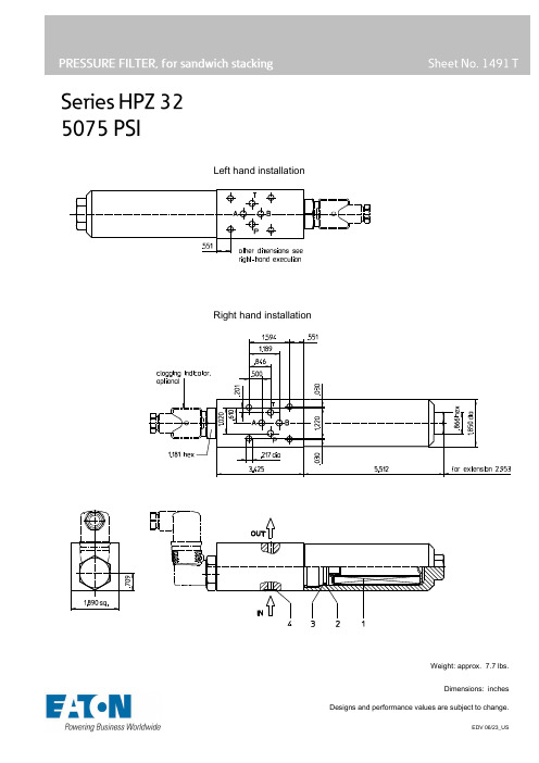
Left hand installationRight hand installationWeight: approx. 7.7 lbs.Dimensions: inchesDescription:The HPZ series filter is a valve protection filter according to DIN 24340-A6 (D03&D05 pattern). . These pressure filters are mounted between the valve and manifold to provide extra protection for critical valves. The HPZ filter can be mounted on either side of the valve for easy filter maintenance, depending on the filter configuration.The filter element consists of star-shaped, pleated filter material, which is supported on the inside by a perforated core tube and is bonded to the end caps with a high-quality adhesive. The flow direction is from outside to inside. Filter elements are available down to 5 µm(c). Finer filtration is available upon request.For cleaning the stainless steel mesh element or changing the filterer element, remove the cover and take out the element. The mesh elements are not guaranteed to maintain 100% performance after cleaning.Eaton filter elements are known for high intrinsic stability and an excellent filtration capability, a high dirt-retaining capacity and a long service life.Eaton filter elements are available up to a pressure resistance of ∆p 2320 PSI and a rupture strength of ∆p 3625 PSI .Eaton filter can be used for petroleum-based fluids, HW emulsions, water glycols, most synthetic fluids and lubrication fluids. Consult factory for specific fluid applications. 1. Type index:1.1. Complete filter:(ordering example)series:HPZ =pressure filter for sandwich stackingnominal size: 32filter-material and filter-fineness:80G, 40G, 25G, 10G stainless steel wire mesh25VG, 16VG, 10VG, 6VG, 3VG microglassfilter element collapse rating:30 = ∆p 435 PSIHR = ∆p 2320 PSI (rupture strength ∆p 3625 PSI)filter element design:E = single-end opensealing material:P = Nitrile (NBR)V = Viton (FPM)filter element specification:- = standardVA = stainless steelprocess connection:Z =sandwich stacking according to DIN 24340, T2 process connection size:1 = A6 according to DIN 24340, T2filter housing specification:- = standardhead design:R = right-hand installationL = left-hand installationclogging indicator or clogging sensor:- = withoutAOR= visual, see sheet-no. 1606AOC = visual, see sheet-no. 1606AE = visual-electric, see sheet-no. 1615VS5 = electronic, see sheet-no. 1619To add an indicator to your filter, use the correspondingindicator data sheet to find the indicator details and add them to the filter assembly model code.1.2. Filter element: (ordering example)series:01E. = filter element according to company standardnominal size: 30- see type index-complete filterTechnical data:operating temperature: +14°F to +212°Foperating medium mineral oil, other media on requestmax. operating pressure: 5075 PSItest pressure: 7257 PSIprocess connection: (master gauge for holes) DIN 24340-A6housing material: EN-GJS-400-18-LT, C-steel (filter bowl)sealing material: Nitrile (NBR) or Viton (FPM), other materials on requestinstallation position: verticalvolume tank: 0.02 GalClassified under the Pressure Equipment Directive 2014/68/EU for mineral oil (fluid group 2), Article 4, Para. 3.Classified under ATEX Directive 2014/34/EU according to specific application (see questionnaire sheet-no. 34279-4).Pressure drop flow curves:Filter calculation/sizingThe pressure drop of the assembly at a given flow rate Q is the sum of the housing ∆p and the element ∆p and is calculated as follows:∆p assembly= ∆p housing+ ∆p element∆p housing = (see ∆p= f (Q) - characteristics)∆p element (PSI) =Q (GPM) x MSK1000(PSIGPM)x ν(SUS) x ρ0.876(kgdm³)For ease of calculation our Filter Selection tool is available online at /hydraulic-filter-evaluationMaterial gradient coefficients (MSK) for filter elementsThe material gradient coefficients in psi/gpm apply to mineral oil (HLP) with a density of 0.876 kg/dm³ and a kinematic viscosity of 139 SUS (30 mm²/s). The pressure drop changes proportionally to the change in kinematic viscosity and density.∆p = f(Q) – characteristics according to ISO 3968The pressure drop characteristics apply to mineral oil (HLP) with a density of 0.876 kg/dm³. The pressure drop changes proportionally to the density.Symbols:without indicator with electricindicatorAE30 / AE40with visual-electricindicatorAE50 / AE62with visual-electricindicatorAE70 / AE80 / AE90with visualindicatorAOR / AOCwith electronicclogging sensorVS5Spare parts:item qty. designation dimension article-no.1 1 filer element 01E.30…2 1 O-ring 32 x 2,5 306843 (NBR) 308268 (FPM)3 1 support ring SRA 37 x 2,1 x 1 3054664 4 O-ring 9,25 x 1,78 304354 (NBR) 310268 (FPM)Test methods: Filter elements are tested according to the following ISO standards:ISO 2941 Verification of collapse/burst resistanceISO 2942 Verification of fabrication integrityISO 2943 Verification of material compatibility with fluidsISO 3723 Method for end load testISO 3724 Verification of flow fatigue characteristicsISO 3968 Evaluation of pressure drop versus flow characteristicsISO 16889 Multi-pass method for evaluating filtration performanceNorth America44 Apple StreetTinton Falls, NJ 07724Toll Free: 800 656-3344(North America only)Tel: +1 732 212-4700Europe/Africa/Middle EastAuf der Heide 253947 Nettersheim, Germany Tel: +49 2486 809-0Friedensstraße 4168804 Altlußheim, Germany Tel: +49 6205 2094-0An den Nahewiesen 2455450 Langenlonsheim, Germany Tel: +49 6704 204-0 Greater ChinaNo. 7, Lane 280,Linhong RoadChangning District, 200335Shanghai, P.R. ChinaTel: +86 21 5200-0099Asia-Pacific100G Pasir Panjang Road#07-08 Interlocal CentreSingapore 118523Tel: +65 6825-1668For more information, pleaseemail us at ********************or visit /filtration© 2021 Eaton. All rights reserved. All trademarks andregistered trademarks are the property of their respectiveowners. All information and recommendations appearing inthis brochure concerning the use of products described hereinare based on tests believed to be reliable. However, it is theuser’s responsibility to determine the suitability for his ownuse of such products. Since the actual use by others isbeyond our control, no guarantee, expressed or implied, ismade by Eaton as to the effects of such use or the results tobe obtained. Eaton assumes no liability arising out of the useby others of such products. Nor is the information herein to beconstrued as absolutely complete, since additional informationmay be necessary or desirable when particular or exceptionalconditions or circumstances exist or because of applicablelaws or government regulations.。
DAAS 4 Pro音频测试系统操作手册说明书

深圳阳光丽声仪器设备有限公司深圳市音之侣机电有限公司www sunvoice cn com email 138****6201163com 138****6201075529593393075589472581808.-. :@.手机: 电话:- 传真:--******************************************郑重申明:DAAS公司只提供英文版光盘使用操作手册,没有提供中文版本手册及印刷品. 此中文说明书为本公司翻译,版权为其所有,任何其他公司不得抄袭翻印.公 司 简 介本公司是专业电声测量领域的先导者。
本公司代理国内外各类电声测量仪器及音响、分频器开发设计软件,产品种类齐全;公司成立多年来,包括港、台商在内的众多客户(如松下、TCL王牌、惠阳东亚集团、东莞美隆、深圳隆光等),对我们公司的产品及售后服务给予了很高的评价。
我们已获准成为美国LMS,MLSSA,德国DAAS,ATB,Loudsoft,台湾阳光,意大利CLIO等公司的大陆代理商。
因为有我们美国分部的全力支持,故我们在价格及技术支持方面具有绝对优势。
******************************************DAAS4Pro 硬件安装图示:红白黄接线头按照位置顺序连接,请勿插错************************************************************************************ DAAS4Pro QC简易操作说明一:首先将DAAS卡插入电脑主机,然后安装驱动程序和测试软件.安装完毕后请接好电脑主机与DAAS专用功放之间的所有连接线缆并打开功放电源.(请注意,在以后进行测试操作时一定要先打开功放电源再打开测试软件,此点十分重要).当你装完DAAS卡的驱动后在你的电脑屏幕右下角会出现一个这样的图标,请双击它会出现下图:备注:此项设置是首次安装完驱动软件后必须要进行的,此设置只需进行一次.二:进入测试界面,首先双击桌面DAAS快捷图标,第一次会出现如下图所示的提示: 2:点击此处 ******************************************点击OK 进入下一画面,请按照图上的步骤操作:会出现下图:1:首先点击此处 ******************************************然后点击再按Esc 退出测试程序之后再重新进入测试程序,就会听到功放中的继电器切换几次,这是系统在检测电脑与功放之间的连接是否正常.如果一切正常就可进入下一步的操作.三:重新双击桌面上的DAAS 快捷图标会进入测试界面,我们首先调节测试电压,如下图所示:当选择好合适的电压后,我们开始进行下一步操作. ******************************************首先选择测试项目,我们先测试频响,如下图:接着点击F1会出现如下界面:选择F1******************************************还是选择F1开始接着选择F1点击OK******************************************选择F1点击F1出现下图所示的测试曲线,然后点击F5 ******************************************选择想要保存的路径和文件名称(路径和文件名称请按需要自己设定).保存完毕后请点击F7出现如下画面,再选择F9点击此处保存曲线******************************************出现如下图后请按照需要进行选择我们选择F1手绘上下限文件,会出现下图点击此处F1手绘上下限F2载入上下限F3存储上下限F4删除上下限******************************************点击此处用鼠标左键首先选择上限的起始位置,之后延样品曲线走势连续点击即可绘出上限(此处注意,选择F1手绘上下限文件时一定要先绘上限),之后点击鼠标右键会出现如下画面:继续选择此处 ******************************************用相同方法绘出下限,如下图:点F7,再F9,得出下图:出现如下图所示后选择路径,保存文件.(注意保存路径一定要和样品曲线的路径一致,即要在同一文件夹)选择F3保存上下限文件******************************************2.再点击OK ******************************************出现下图后先选择Quality Control(QC 品管控制)然后点击F1或者踩脚踏开关则开始QC测试,如下为测试结果图 ******************************************出现如下图所示画面后此时就会出现你所要的结果曲线,现在请点F5保存曲线,如下图,选择自己想要保存的文件名称和路径保存 ******************************************方法与频响上下限绘制方法一样再选择F1绘制上下限公差 ******************************************绘制完毕后出现如下图所示画面:如下图所示先选择F9,再选择F3保存上下限公差文件出现如下图所示后选择路径,保存文件.(注意保存路径一定要和样品曲线的路径一致,即要在同一文件夹)2,再选择F3******************************************然后进行QC测试,方法与频响QC测试一致.下图为频响,阻抗QC测试完毕后的画面: ******************************************(1)更改显示频率范围:如下框中先输入起始频率后点击ok ,再输入截至频率:.(2)要在同一画面显示多条频响曲线或者频响和阻抗曲线同时显示在同一1.在测试出结果后点击这里的F7 ******************************************画面,可以先将测试的曲线保存,然后测试另外一个频响曲线后在画面上点击File-Load Curve(载入曲线),选择刚才保存的文件名则可将刚才保存的曲线调入同一画面. ******************************************手动设置DAAS4系统功放输出电压/电平(1) 若被测试扬声器的阻抗为8欧姆,则在1M1W 的测试距离功放输出应该为8开根号=2.83V 来测试,麦克风和被测试扬声器的距离为1M(2) DAAS4输出电压/电平单位只有dB 没有V ,因此要经过换算,2V=22dB, 2.83V =19dB,179mV=43dB下图:出现如下画面,(3) 回到测试软件界面,测试频响曲线,麦克风和被测试扬声备注:若不用手动设置方法,可点选此软件自动换算设置,让软件自动换算成1M1W 测试结果,只更改这里被测试喇叭阻抗数值即可。
點擊下載此文件
板名: Impress、Firefox 心得討論 篇號/總數: 2 / 38 張貼者: bbweks (張雅玲 ) 張貼時間: 2009-11-09 20:24:30 標題: 督促自己學習 以前沒自己操作過 power point ,更沒使用過 impress、firefox,算是個電腦新手, 利用這次參加 k12 數位課程,督促自己好好學習。感謝傑恒老師用淺顯易懂的方 式講解這個課程,而且分成好幾個小主題,讓我們能一點一點的消化吸收這些步 驟,感恩您~~
4
板名: 二.免費 WhiteBoard 軟體討論 篇號/總數: 18 / 28 張貼者: bbweks (張 雅玲 ) 張貼時間: 2009-11-18 22:21:19 標題: 電子白板之優缺點比較 這次課程中所介紹的免費電子軟體最大的優勢就是免付費、容易學習、取得容 易,而且用在講解重點、檢討考卷之類的課程,會更清楚明瞭。不過視覺效果較 弱一點,班上的小朋友(低年級)比較不容易被吸引,加上我用滑鼠寫起字來較不 靈活,所以會減低使用的意願。
對於心智圖用於分類的教學活動,是相當適合的。未來也可以將此模式應用在學 生觀察生物的紀錄上,相信也能瞭解學生是否具有清楚的概念。謝謝您的分享!
李忠屏敬上
At 2009-11-07 18:12:51 bbweks (張雅玲 ) wrote :
請多指教,感恩喲!
板名: Xmind 心智圖成果分享 篇號/總數: 52 / 67 張貼者: bbweks (張雅玲 ) 張 貼時間: 2009-11-08 07:13:57 標題: Re: 交 xmind 心智圖作業 忠屏老師~~您教我們的心智圖真的很實用呢!還來不及做成電腦圖檔來教課
At 2009-11-05 17:42:41 tom_chhps (湯應麟 ) wrote :
卡西欧电子词典 如何导入文本 电子书

前言
在使用本软件前,请务必认真阅读该使用说明书,以便您正确使用 本软件。 此外,阅读后,请妥善保管此说明书。 本说明书是介绍“译天下 TextLoader”软件及电子辞典本机“我的 书库”功能的说明书。
特点
●阅读网络下载的Free eBook 本产品可以阅读WEB站点免费提供的文本格式(扩展名为.txt)eBook。 将文本文件下载到电脑上,再传送到电子辞典中。→第3页
软件运行环境
OS(简体版本):Microsoft Windows 98/98SE/Me/ 2000 Professional/XP Home Edition/ XP Professional、Windows Vista
※在Windows 3.1/95、Windows NT或Macintosh/Mac OS上无法运行。 ※ 根据电脑的配置(CPU/硬盘容量/内存容量等)有可能导致无法正常运行。 ※不保证在通过其他OS升级的Windows 98/98SE/Me/2000 Professional/XP Home
Edition/XP Professional、Windows Vista环境下的运行。 ※只支持Windows Vista的32位版本。 ※不支持Windows XP Professional x64 Edition。
-2-
阅读“Free eBook”
请务必先将“译天下 TextLoader”安装到所使用的电脑中,然后 再连接电子辞典与电脑。
① 对压缩文件进行解压缩。
双击
。
② 按照显示的信息进行安装。 • 使用Windows Vista时,显示“用户帐户控制”画面。请单击“取消”或“允
许(A)”。
③ 安装完成后,桌面上会显示
- 1、下载文档前请自行甄别文档内容的完整性,平台不提供额外的编辑、内容补充、找答案等附加服务。
- 2、"仅部分预览"的文档,不可在线预览部分如存在完整性等问题,可反馈申请退款(可完整预览的文档不适用该条件!)。
- 3、如文档侵犯您的权益,请联系客服反馈,我们会尽快为您处理(人工客服工作时间:9:00-18:30)。
Exam:HP HP0-D05
Title:Designing HP Virtualization
Solutions
Version:Demo
1.In addition to CPU and memory utilization,which type of data does Capacity Advisor gather?
er load data
B.disk I/O data
C.cell partition data
D.system error data
Answer:B
2.What is the name of the connection broker technology included in the VMware product offering for desktop virtualization and virtual desktop management?
A.Session Allocation Manager(SAM)
B.Desktop Delivery Controller(DDC)
C.View Manager
D.vWorkspace
Answer:C
3.Which software-layer abstraction of the server hardware allows the guest operating system to be aware of its virtualized host(hypervisor)?
A.CPU binary translation
B.hosted OS,application-layer abstraction
C.paravirtualization
D.hardware-assisted virtualization(full virtualization)
Answer:C
4.Which virtualization product uses paravirtualization?
A.Citrix XenServer
B.Microsoft Virtual Server2005R2
C.Virtual Iron
D.VMware ESX3.5
Answer:A
5.Which virtualization products use hosted-OS,application-layer abstraction?(Select two.)
A.Citrix XenServer
B.Red Hat Enterprise Linux
C.Microsoft Virtual Server2005R2
D.VMware Server
E.VMware ESX
Answer:CD
6.Which virtualization products use hardware-assisted virtualization(full virtualization)?(Select three.)
A.Citrix XenServer
B.Red Hat Enterprise Linux
C.Windows Server2008Hyper-V
D.VMware Server
E.VMware vSphere
Answer:ACE
7.Which flexible Virtual Server2005clustering scenario provides high availability for mission critical environments while improving patching and hardware maintenance processes?(Select two.)
A.guest to guest:Cluster guest to guest across virtual machines with iSCSI
B.host to host:Cluster all virtual machines running on a host
C.guest to host:Cluster guest to host across physical machines with iSCSI
D.host to guest:Cluster all virtual machines running on distributed hosts
E.guest to guest:Cluster guest to guest across virtual machines running on SCSI connected hosts Answer:AB
8.Which virtualized guests does Red Hat Enterprise Linux support?(Select two.)
A.paravirtualized
B.platform virtualization
work virtualization
D.full virtualization
E.emulated virtualization
Answer:AD
9.Which HP SAN Virtualization Services Platform(SVSP)features are available when working with multiple remote domains?(Select two.)
A.snapclones
B.enhanced asynchronous mirrors
C.asynchronous mirrors
D.synchronous mirrors
E.snapshots
Answer:AC
10.A customer has a mission critical application running as a virtual machine and needs to protect against any type of hardware failure.Which VMware vSphere feature meets this requirement?
A.VMware Data Recovery
B.VMware VMsafe
C.VMware Fault Tolerance
D.VMware vShield Zones
Answer:C。
