MMSZ62中文资料
MR62系列迷你信号传递器数据表说明书
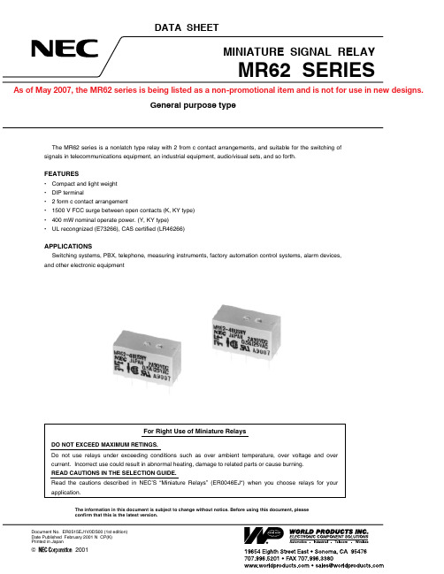
Data Sheet ER0515EJ1V0DS2PIN CONFIGURATIONS (BOTTOM VIEW)(not energized)Note The coil has no polarity.PAD LAYOUT Unit: mm (inch)NoteGeneral tolerance ±0.2 (0.008) mmOUTLINE DRAWINGS AND DIMENSIONS Unit: mm (inch)Note The tolerance is ±0.2 (0.008) unless otherwise specified.The dimension in the box shows basic size.MAKING (SIDE VIEW)General type<1><2><3><4><5>Part numberManufacturer Country of originDate codeUL, CSA markingUL recognized, CSA certified typeData Sheet ER0515EJ1V0DS3SPECIFICATIONSTypesMR62-**MR62-**K**MR62-****YMR62-**K*YContact Form 2 Form cContact Material Silver alloy with gold alloy overlay Contact RatingsMaximum Switching Power 60 W, 125 A Maximum Switching Voltage 220 Vdc, 250 Vac Maximum Switching Current 2 A Maximum Carrying Current2 AMinimum Contact Ratings 100 mVdc, 100 μA Initial Contact Resistance 50 m Ωtyp. (Intial)Nominal Operating Power Approx. 550 mW Approx. 400 mW Operate Time (Excluding bounce)Approx. 2.5msApprox. 3.5msApprox. 2.5 msRelease Time (Excluding bounce without diode)Approx. 2 ms Insulation Resistance 1000 M Ω at 500 Vdc Withstand VoltageBetween open contacts 500 Vac *11000 Vac *11500 V surge *2500 Vac *11000 Vac *11500 V surge *2Between adjacent contacts Between coil to contacts1000 Vac *11500 V surge *2Shock Resistance 294 m/s 2 (misoperating)980 m/s 2 (destructive failure)Vibration Resistance 10 to 55 Hz, double amplitude 1.5 mm (misoperating)10 to 55 Hz, double amplitude 5 mm (destructive failure)Ambient Temperature −40 to +85°C (−40 to +70°C at 48 V coil)Coil Temperature Rise 40°C(550 mW)40°C(550 mW)35°C (400 mW)Running SpecificationsNonload 10× 106 operationsLoad50 Vdc, 0.1 A (resistive) 1 × 10⁶ operations at 85°C, 5 Hz 10 Vdc, 10 mA (resistive) 1 × 10⁶ operations at 85°C, 2 HzWeight Approx. 5 g*1 for one minute*2 rise time: 10 μs, decay time to half crest: 160 μs.PART NUMBER SYSTEMMR62-5UKSRY: 550 mW : 400 mW: Silver-palladium alloy with gold alloyoverlay: Silver-nickel alloy with gold alloyoverlay Sealed type (Washable)Nominal coil voltage (See part numbers)Nominal operate power Nil Y Contact materialNil R : 500 Vac : 1000 VacBreakdown voltage between open contacts Nil K : Standard type: UL recognized CSA certified typeSafety standard Nil U SAFETY STANDARD AND RATING*Spacing: UL114, UL478UL Recognized (UL508)*File No E73266CSA Certificated (CSA C22.2 No14)File No LA4626630 Vdc, 2 A (Resistive)110 Vdc, 0.6 A (Resistive)125 Vac, 1 A (Resistive)PRODUCT LINEUPRemarks:1. Drive under nominal coil voltage. If it is impossible, please inquire of NEC.2. Must Operate Voltage and Must Release Voltage are tested by pulse voltage.3. MAXIMUM COIL VOLTAGE is maximum value of permissible alteration.At continuous use of the voltage, please Inquiry for NEC.Standard type(at 20°C)Part Number Nominal Voltage(Vdc)Coil Resistance(Ω)±10%Must Operate Voltage(Vdc)Must Release Voltage(Vdc)MR62-5SR542 3.10.25MR62-6SR666 3.90.33MR62-9SR9140 5.70.45MR62-12SR122808.10.68MR62-24SR24105015.8 1.3MR62-48SR48420034.4 2.6High-breakdown voltage type(at 20°C)Part Number Nominal Voltage(Vdc)Coil Resistance(Ω)±10%Must Operate Voltage(Vdc)Must Release Voltage(Vdc)MR62-5KSR542 3.50.25MR62-6KSR666 4.20.33MR62-9KSR9140 6.30.45MR62-12KSR122808.40.68MR62-24KSR24105016.8 1.3MR62-48KSR48420038.4 2.6Low power consumption type(at 20°C)Part Number Nominal Voltage(Vdc)Coil Resistance(Ω)±10%Must Operate Voltage(Vdc)Must Release Voltage(Vdc)MR62-5SRY562.5 3.50.25 MR62-6SRY690 4.20.33 MR62-9SRY9202.5 6.30.45 MR62-12SRY123608.40.68 MR62-24SRY24144016.8 1.3 MR62-48SRY48576034.4 2.6Data Sheet ER0515EJ1V0DS4High-breakdown voltage, low power consumption type(at 20°C)Part Number Nominal Voltage(Vdc)Coil Resistance(Ω)±10%Must Operate Voltage(Vdc)Must Release Voltage(Vdc)MR62-5KSRY562.5 3.50.25MR62-6KSRY690 4.20.33MR62-9KSRY9202.5 6.30.45MR62-12KSRY123608.40.68MR62-24KSRY24144016.8 1.3MR62-48KSRY48536038.4 2.6 Standard type (UL recognized, CSA certified)(at 20°C)Part Number Nominal Voltage(Vdc)Coil Resistance(Ω)±10%Must Operate Voltage(Vdc)Must Release Voltage(Vdc)MR62-5USR542 3.10.25MR62-6USR666 3.90.33MR62-9USR9140 5.70.45MR62-12USR122808.10.68MR62-24USR24105015.8 1.3MR62-48USR48420034.4 2.6High-breakdown voltage type (UL recognized, CSA certified)(at 20°C)Part Number Nominal Voltage(Vdc)Coil Resistance(Ω)±10%Must Operate Voltage(Vdc)Must Release Voltage(Vdc)MR62-5UKSR542 3.50.25MR62-6UKSR666 4.20.33MR62-9UKSR9140 6.30.45MR62-12UKSR122808.40.68MR62-24UKSR24105016.8 1.3MR62-48UKSR48420038.4 2.6Data Sheet ER0515EJ1V0DS5Low power consumption type (UL recognized, CSA certified)(at 20°C)Part Number Nominal Voltage(Vdc)Coil Resistance(Ω)±10%Must Operate Voltage(Vdc)Must Release Voltage(Vdc)MR62-5USRY562.5 3.50.25MR62-6USRY690 4.20.33MR62-9USRY9202.5 6.30.45MR62-12USRY123608.40.68MR62-24USRY24144016.8 1.3MR62-48USRY48576034.4 2.6High-breakdown voltage, low power consumption type (UL recognized, CSA certified)(at 20°C)Part Number Nominal Voltage(Vdc)Coil Resistance(Ω)±10%Must Operate Voltage(Vdc)Must Release Voltage(Vdc)MR62-5KSRY562.5 3.50.25 MR62-6KSRY690 4.20.33 MR62-9KSRY9202.5 6.30.45 MR62-12KSRY123608.40.68 MR62-24KSRY24144016.8 1.3 MR62-48KSRY48536038.4 2.6Data Sheet ER0515EJ1V0DS6Data Sheet ER0515EJ1V0DS7543210SWITCHING CAPACITYC o n ta c t c u r r e n t (A )Applied power (W)with diodewithout diodeAPPLIED VOLTAGE vs. TIMINGO p e r a t e t i m e (m s )Sample: MR62-5SR 20 pieces Armbient temperature: Room temperatureO p e r a t e v o l t a g e (V )R e l e a s e v o l t a g e (V )10Applied power (W)R e l e a s e t i m e (m s )1005001000Applied power (mW)COIL TEMPERATURE RISEC o i l t e m p e r a t u r e r i s e (d e g r e e )806040200501234Operations (×104)O p e r a t e v o l t a g e (V )R e l e a s e v o l t a g e (V )12345Operations (×104)86420RUNNING TEST (Nonload)Data Sheet ER0515EJ1V0DS8ALTERNATION OF VOLTAGE AT DENSELY MOUNTING (Magnet interference)–10Mounting layoutAlternation of operate voltageA r a t i o o f a l t e r n a t i o n (%)Mounting layoutAlternation of release voltageA r a ti o o f a l t e r n a t i o n (%)+30+20+100–20–30–40+40NoteThe installation method and the installation pitch of the relay in this examination are as follows.ON ON ONOFFONONOFFOFFIII IVOFF OFF OFFPACKAGEThe relay is stuffed the tube as follows, packed, and shipped.Dimension of Relay Tube (Unit: mm)25 pieces/tubeMaterial: Polyvinyl chloride (anti-static treated)Outline of PackageData Sheet ER0515EJ1V0DS9Notes on Correct Use1. Notes on contact loadMake sure that the contact load is within the specified range; otherwise, the lifetime of the contacts will be shortened considerably. Note that the running performance shown is an example, and that it varies depending on parameters such as the type of load, switching frequency, driver circuit, and ambient temperature under the actual operating conditions. Evaluate the performance by using the actual circuit before using the relay.2. Driving relays- If the internal connection diagram of a relay shows + and – symbols on the coil, apply the rated voltage to the relay in the specified direction. If a rippled DC current source is used, abnormalities such as beat at the coil may occur.- The maximum voltage that can be applied to the coil of the relay varies depending on the ambient temperature. Generally, the higher the voltage applied to the coil, the shorter the operating time. Note, however, that a high voltage also increases the bounce of the contacts and the contact opening and closing frequency, which may shorten the lifetime of the contacts.- If the driving voltage waveform of the relay coil rises and falls gradually, the inherent performance of the relay may not be fully realized. Make sure that the voltage waveform instantaneously rises and falls as a pulse.- For a latching relay, apply a voltage to the coil according to the polarity specified in the internal connection diagram of the relay.- If a current is applied to the coil over a long period of time, the coil temperature rises, promoting generation of organic gas inside the relay, which may result in faulty contacts. In this case, use of a latching relay is recommended.- The operating time and release time indicate the time required for each contact to close after the voltage has been applied to or removed from the coil. However, because the relay has a mechanical structure, a bounce state exists at the end of the operating and release times. Furthermore, because additional time is required until the contact stabilizes after being in a high-resistance state, care must be taken when using the relay at high speeds.3. Operating environment- Make sure that the relay mounted in the application set is used within the specified temperature range. Use of a relay at a temperature outside this range may adversely affect insulation or contact performance.- If the relay is used for a long period of time in highly humid (RH 85% or higher) environment, moisture may be absorbed into the relay. This moisture may react with the NOx and SOx generated by glow discharges that occur when the contacts are opened or closed, producing nitric or sulfuric acid. If this happens, the acid produced may corrode the metallic parts of the relay, causing operational malfunction.- Because the operating temperature range varies depending on the humidity, use the relay in the temperature range illustrated in the figure below. Prevent the relay from being frozen and avoid the generation ofcondensation.Data Sheet ER0515EJ1V0DS104. Notes on mounting relays- When mounting a relay onto a PC board using an automatic chip mounter, if excessive force is applied to the cover of the relay when the relay is chucked or inserted, the cover may be damaged or the characteristics of the relay degraded. Keep the force applied to the relay to within 1 kg.- Avoid bending the pins to temporarily secure the relay to the PC board. Bending the pins may degrade sealability or adversely affect the internal mechanism.- It is recommended to solder the relay onto a PC board under the following conditions: <1> Reflow solderingRefer to the recommended soldering temperature profile. <2> Flow solderingSolder temperature: 250°C max., Time: 5 to 10 seconds, Preheating: 100°C max./1 minute max. <3> Manual solderingSolder temperature: 350°C, Time: 2 to 3 seconds- Ventilation immediately after soldering is recommended. Avoid immersing the relay in cleaning solvent immediately after soldering due to the danger of thermal shock being applied to the relay.- Use an alcohol-based or water-based cleaning solvent. Never use thinner and benzene because they may damage the relay housing.- Do not use ultrasonic cleaning because the vibration energy generated by the ultrasonic waves may cause the contacts to remain closed.5. Handling- Relays are packaged in magazine cases for shipment. If a space is created in the case after some relays have been removed, be sure to insert a stopper to secure the remaining relays in the case. If relays are not well secured, vibration during transportation may cause malfunctioning of the contacts.- Exercise care in handling the relay so as to avoid dropping it or allowing it to fall. Do not use a relay that has been dropped. If a relay drops from a workbench to the floor, a shock of 9,800 m/s 2 (1,000 G) or more is applied to the relay, possibly damaging its functions. Even if a light shock has been applied to the relay, thoroughly evaluate its operation before using it.- Latching relays are factory-set to the reset state for shipment. A latching relay may be set, however, by vibration or shock applied while being transported. Be sure to forcibly reset the relay before using it in the application set. Also note that the relay may be set by unexpected vibration or shock when it is used in a portable set.- The sealability of a surface-mount relay may be lost if the relay absorbs moisture and is then heated during soldering. When storing relays, therefore, observe the following points:1. The storage humidity must be no more than 70% RH. The recommended storage period is 3 months maximum.2. To store the relay for 3 months or longer, keep the storage humidity to within 50% RH. Do not store the relay for more than 6 months.- The relay maintains constant sealability under normal atmospheric pressure (810 to 1,200 hpa). Its sealability may be degraded or the relay may be deformed and malfunction if it is used under barometric conditions exceeding the specified range.- The same applies when the relay is stored or transported. Keep the upper-limit value of the temperature to which the relay is exposed after it is removed from the carton box to within 50°C.- If excessive vibration or shock is applied to the relay, it may malfunction and the contacts remain closed. Vibration or shock applied to the relay during operation may cause considerable damage to or wearing of the contacts. Note that operation of a snap switch mounted close to the relay or shock due to the operationof magnetic solenoid may also cause malfunctioning.H u m i d i t y (%R H )85806040205−60−40−2020406080100Temperature (°C)No part of this document may be copied or reproduced in any form or by any means without theprior written consent of NEC Corporation. NEC Corporation assumes no responsibility for anyerrors which may appear in this document.NEC Corporation does not assume any liability for infringement of patents, copyrights or otherintellectual property rights of third parties by or arising from use of a device described herein ora n y o t h e r l i ab i l i t y a r i s i n g f r o m u s e o f s uc hde v i c e.N o l i c e n s e,e i t h e r e x p r e s s,i m p l i e d o rotherwise, is granted under any patents, copyrights or other intellectual property rights of NECCorporation or others.W h i l e N E C C o r p o r a t i o n h a s b e e n m a k i n g c o n t i n u o u s e f f o r t t o e n h a n c e t h e r e l i a b i l i t y o f i t se l e c t r o n i c components, the possibility of defects cannot be eliminated entirely. To minimize risksof damage or injury to persons or property arising from a defect in an NEC electronic component,customers must incorporate sufficient safety measures in its design, such as redundancy, fire-containment, and anti-failure features. NEC devices are classified into the following three qualitygrades:"S t a n d a r d,""S p e c i a l,"a n d"S p e c i f i c".T h e S p e c i f i c q u a l i t y g r a d e a p p l i e s o n l y t o d e v i c e sd e v e l o p e d b a s e d o n a c u s t o m e r d e s i g n a t e d"q u a l i t y a s s u r a n c e p r o g r a m"f o r a s p e c i f i capplication. The recommended applications of a device depend on its quality grade, as indicatedbelow. Cust omers must check the qualit y grade of each device before using it in a particularapplicat ion.Standard: Computers, office equipment, communications equipment, test and measurementequipment, audio and visual equipment, home electronic appliances, machine tools,personal electronic equipment and industrial robotsSpecial: Transportation equipment (automobiles, trains, ships, etc.), traffic control systems,a n t i-d i s a s t e r s y s t e m s,a n t i-c r i m e s y s t e m s,s a f e t y e q u i p m e n t a n d m e d i c a le q u i p m e n t(n o t specifically designed for life support)S p e c i f i c: A i r c r a f t s,a e r o s p a c e e q u i p m e n t,s u b m e r s i b l e r e p e a t e r s,n u c l e a r r e a c t o r c o n t r o lsystems, life support systems or medical equipment for life support, etc.The quality grade of NEC devices is "Standard" unless otherwise specified in NEC's Data Sheetso r D a t a B o o k s.I f c u s t o m e r s i n t e n d t o u s e N E C d e v i c e s f o r a p p l i c a t i o n s o t h e r t h a n t h o s es p e c i f i e d f o r S t a n d a r d q u a l i t y g r a d e,t h e y s h o u l d c o n t a c t a n N E C s a l e s r e p r e s e n t a t i v e i na d v a n c e.(Note)(1) "N E C"a s u s e d i n t h i s s t a t e m e n t m e a n s N E C C o r p o r a t i o n a n d a l s o i n c l u d e s i t s m a j o r i t y-owned subsidiaries.(2) "NEC electronic component products" means any electronic component product developedor manufactured by or for NEC (as defined above).DE0202 3/01Mouser ElectronicsAuthorized DistributorClick to View Pricing, Inventory, Delivery & Lifecycle Information:N EC:MR62-5USR MR62-48USRY MR62-5UKSRY MR62-12USR MR62-24FSRYP4MR62-12UKSRY MR62-24USRY MR62-5USRY MR62-24UKSRY MR62-48USR MR62-24USR MR62-12USRY MR62-48UKSRY。
中英文国家对照表

中英文国家对照表相信大部分Aff跑的offer不仅仅局限于几个熟悉的国家,那当我们遇到不熟悉的国家和地区,或者想知道中文国家名称对应的英文名称,抑或反过来想知道英文国家名称对应的中文名称时,我们就需要到处查找与这有关的资料,这往往消耗掉了我们大量的时间和精力。
现在金橙子海外联属营销网用一个表格集成了大部分数据,包括全球所有国家和地区的中英文、国家代码、以及人口数据。
表格是基于ISO3166标准整理而来,一起来看看。
序号ISO英文名称中文名称人口数据(默认:万)人均GDPE-Packet1AD Andorra安道尔72AE United Arab Em.阿联酋927 3AF Afghanistan阿富汗3,3374AG Antigua andBarbuda安提瓜和巴布达95AI Anguilla安圭拉16AL Albania阿尔巴尼亚290 7AM Armenia亚美尼亚3038AN NetherlandsAntilles荷属安的列斯群岛189AO Angola安哥拉2,583 10AR Argentina阿根廷4,385 11AS American Samoa美属萨摩亚612AT Austria奥地利857序号ISO英文名称中文名称(默认:万)均GDPE-Packet13AU Australia澳大利亚2,431Yes 14AW Aruba阿鲁巴群岛1015AZ Azerbaijan阿塞拜疆98716BA Bosnia波斯尼亚38017BB Barbados巴巴多斯2918BD Bangladesh孟加拉16,29119BE Belgium比利时1,13720BF Burkina Faso布基纳法索1,86321BG Bulgaria保加利亚71022BH Bahrain巴林14023BI Burundi布隆迪1,15524BJ Benin贝宁1,11725BL Saint Barthelemy 圣巴瑟米(法)26BM Bermuda百慕大627BN Brunei文莱4328BO Bolivia玻利维亚1,08929BQ Bonaire SintEustatius Saba荷兰加勒比区30BR Brazil巴西20,957 31BS Bahamas巴哈马3932BT Bhutan不丹7833BV Bouvet Island 布韦岛(挪)序号ISO英文名称中文名称(默认:万)均GDPE-Packet34BW Botswana博茨瓦纳23035BY Belarus白俄罗斯94836BZ Belize伯利兹3737CA Canada加拿大3,629Yes38CC Cocos (Keeling)Islands科科斯群岛039CD The DemocraticRepublic of theCongo刚果民主共和国7,97240CF Central AfricanRepublic中非共和国50051CG Congo刚果47442CH Switzerland瑞士83843CI Côte d'Ivoire科特迪瓦2,325 44CK Cook Islands库克群岛245CL Chile智利1,813 46CM Cameroon喀麦隆2,392 47CN China中国138,232 48CO Colombia哥伦比亚4,865 49CR Costa Rica哥斯达黎加48650CU Cuba古巴1,139 51CV Cape Verde佛得角5352CW Curacao库拉索1653CX Christmas Island圣诞岛054CY Cyprus塞浦路斯118序号ISO英文名称中文名称(默认:万)均GDPE-Packet55CZ Czech捷克1,055 56DE Germany德国8,068 57DJ Djibouti吉布提9058DK Denmark丹麦56959DM Dominica多米尼克760DO Dominican Rep多米尼加1,065 61DZ Algeria阿尔及利亚4,038 62EC Ecuador厄瓜多尔1,639 63EE Estonia爱沙尼亚13164EG Egypt埃及9,338 65EH Western Sahara西撒哈拉5866ER Eritrea厄立特里亚53567ES Spain西班牙4,606 68ET Ethiopia埃塞俄比亚10,185 69EU EU欧盟70FI Finland芬兰55271FJ Fiji斐济9072FK Falkland Islands (Malvinas)福克兰群岛(马尔维纳斯群岛)73FM Micronesia,Federated Statesof密克罗尼西亚联邦1074FO Faroe Islands法罗群岛575FR France法国6,467序号ISO英文名称中文名称(默认:万)均GDPE-Packet76GA Gabon加蓬17677GB Great Britain英国6,511Yes 78GD Grenada格林纳达1179GE Georgia格鲁吉亚39880GF French Guiana法属圭亚那2881GG Guernsey格恩西岛782GH Ghana加纳2,80383GI Gibraltar直布罗陀384GL Greenland格陵兰685GM Gambia冈比亚20586GN Guinea几内亚1,29587GP Guadeloupe瓜德罗普4788GQ Equatorial Guinea赤道几内亚8789GR Greece希腊1,09290GS South Georgia andthe Islands南乔治亚岛091GT Guatemala危地马拉1,667 92GU Guam关岛1793GW Guinea-Bissau几内亚比绍189 94GY Guyana圭亚那7795HK Hong Kong中国香港73596HM Heard Island andMcDonald Islands赫德岛和麦克唐纳群岛97HN Honduras洪都拉斯819序号ISO英文名称中文名称(默认:万)均GDPE-Packet98HR Croatia克罗地亚42399HT Haiti海地1,085 100HU Hungary匈牙利982101ID Indonesia印度尼西亚26,058 102IE Ireland爱尔兰471103IL Israel以色列819104IN India印度132,680105IO British IndianOcean Territory英属印度洋领地106IQ Iraq伊拉克3,755 107IR Iran伊朗8,004 108IS Iceland冰岛33109IT Italy意大利5,980 110JM Jamaica牙买加280 111JO Jordan约旦775 112JP Japan日本12,632 113KE Kenya肯尼亚4,725114KG Kyrgyzstan 吉尔吉斯斯坦603115KH Cambodia柬埔寨1,583 116KI Kiribati基里巴斯11 117KM Comoros科摩罗81118KN Saint Kitts andNevis圣基茨和尼维斯6序号ISO英文名称中文名称(默认:万)均GDPE-Packet119KP DemocraticPeople's Republicof Korea朝鲜2,528120KR South Korea韩国5,050121KV The Republic ofKosovo科索沃180122KW Kuwait科威特401 123KY Cayman Islands开曼群岛6124KZ Kazakhstan哈萨克斯坦1,786 125LA Laos老挝692 126LB Lebanon黎巴嫩599 127LC Saint Lucia圣卢西亚19 128LI Liechtenstein列支敦士登4129LK Sri Lanka斯里兰卡2,081 130LR Liberia利比里亚462 131LS Lesotho莱索托216 132LT Lithuania立陶宛285 133LU Luxembourg卢森堡58 134LV Latvia拉脱维亚196 135LY Libya利比亚633 136MA Moroco摩洛哥3,482 137MC Monaco摩纳哥4138MD Republic ofMoldova摩尔多瓦406139ME Montenegro黑山63序号ISO英文名称中文名称(默认:万)均GDPE-Packet140MG Madagascar马达加斯加2,492 141MH Marshall Islands马绍尔群岛5142MK Republic ofMacedonia马其顿208143ML Mali马里1,813 144MM Myanmar缅甸5,436 145MN Mongolia蒙古301 146MO Macau中国澳门60147MP Northern MarianaIslands北马里亚纳群岛6148MQ Martinique马提尼克40149MR Mauritania毛里塔尼亚417 150MS Montserrat蒙特塞拉特1151MT Malta马耳他42152MU Mauritius毛里求斯128 153MV Maldives马尔代夫37154MW Malawi马拉维1,775 155MX Mexico墨西哥12,863 156MY Malaysia马来西亚3,075 157MZ Mozambique莫桑比克2,875 158NA Namibia纳米比亚251159NC New Caledonia 新喀里多尼亚27160NE Niger尼日尔2,072序号ISO英文名称中文名称(默认:万)均GDPE-Packet161NF Norfolk Island诺福克岛0162NG Nigeria尼日利亚18,699163NI Nicaragua尼加拉瓜615164NL Netherlands荷兰1,698165NO Norway挪威527166NP Nepal尼泊尔2,885167NR Nauru瑙鲁1168NU Niue纽埃0169NZ New Zealand新西兰457Yes 170OM Oman阿曼465171PA Panama巴拿马399172PE Peru秘鲁3,177173PF French Polynesia 法属波利尼西亚29174PG Papua New Guinea 巴布亚新几内亚778175PH Philippines菲律宾10,225 176PK Pakistan巴基斯坦19,283 177PL Poland波兰3,859178PM Saint Pierre andMiquelon圣皮埃尔和密克隆1179PN Pitcairn皮特凯恩0 180PR Puerto Rico波多黎各368 181PS Gaza Strip加沙地带220序号ISO英文名称中文名称(默认:万)均GDPE-Packet182PT Portugal葡萄牙1,030 183PW Palau帕劳2184PY Paraguay巴拉圭673 185QA Qatar卡塔尔229 186RE Reunion留尼旺群岛87187RO Romania罗马尼亚1,937 188RS Serbia塞尔维亚881 189RU Russia俄罗斯14,344 190RW Rwanda卢旺达1,188 191SA Saudi Arabia沙特阿拉伯3,216 192SB Solomon Islands所罗门群岛59193SC Seychelles塞舌尔10194SD Sudan苏丹4,118 195SE Sweden瑞典985 196SG Singapore新加坡570197SH Saint Helena,Ascension andTristan Da Cunha圣赫勒拿,阿森松岛和特里斯坦达库尼亚198SI Slovenia斯洛文尼亚207199SJ Svalbard 斯瓦尔巴特群岛200SK Slovakia斯洛伐克543 201SL Sierra Leone塞拉利昂659 202SM San Marino圣马力诺3序号ISO英文名称中文名称(默认:万)均GDPE-Packet203SN Senegal塞内加尔1,559 204SO Somalia索马里1,108 205SR Suriname苏里南55 206SS South Sudan南苏丹1,273207ST Sao Tome andPrincipe圣多美和普林西比19208SV El Salvador萨尔瓦多615 209SX Sint Maarten荷属圣马丁4210SY Syrian ArabRepublic叙利亚1,856211SZ Swaziland斯威士兰130212TC Turks and CaicosIslands特克斯和凯科斯群岛3213TD Chad乍得1,450 214TG Togo多哥750 215TH Thailand泰国6,815 216TJ Tajikistan塔吉克斯坦867 217TK Tokelau托克劳群岛0218TL East Timor东帝汶121 219TM Turkmenistan土库曼斯坦544 220TN Tunisia突尼斯1,138 221TO Tonga汤加11 222TR Turkey土耳其7,962223TT Trinidad andTobago特里尼达和多巴哥136序号ISO英文名称中文名称(默认:万)均GDPE-Packet224TV Tuvalu图瓦卢1225TW Taiwan中国台湾2,340226TZ Tanzania, UnitedRepublic of坦桑尼亚5,516227UA Ukraine乌克兰4,462 228UG Uganda乌干达4,032229UM United StatesMinor OutlyingIslands美国本土外小岛屿230US USA美国32,412Yes 231UY Uruguay乌拉圭344232UZ Uzbekistan 乌兹别克斯坦3,030233VA Vatican CityState梵蒂冈0234VC Saint Vincent andthe Grenadines圣文森特和格林纳丁斯11235VE Venezuela委内瑞拉3,152236VG British Virginlslands英属维尔京群岛3237VI Virgin Islands维京群岛11 238VN Vietnam越南9,444 239VU Vanuatu瓦努阿图27240WF Wallis and Futuna 瓦利斯群岛和富图纳群1序号ISO英文名称中文名称(默认:万)均GDPE-Packet岛241WS Samoa萨摩亚19 242YE Yemen也门2,748 243YT Mayotte马约特岛25 244ZA South Africa南非5,498 245ZM Zambia赞比亚1,672 246ZW Zimbabwe津巴布韦1,597。
MMSZ5242中文资料
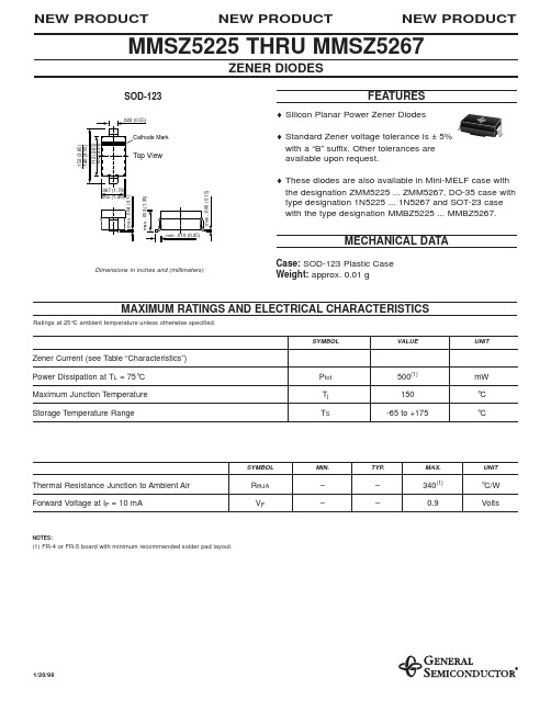
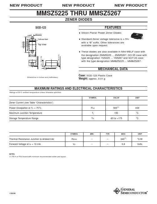
Cathode Mark
.152 (3.85) .140 (3.55) .112 (2.85) .100 (2.55)
Top View
max. .004 (0.1)
max. .053 (1.35)
min. .010 (0.25)
max. .006 (0.15)
.067 (1.70) .055 (1.40)
50 25 15 10 5.0 5.0 5.0 5.0 5.0 5.0 3.0 3.0 3.0 3.0 3.0 3.0 2.0 1.0 0.5 0.1 0.1 0.1 0.1 0.1 0.1 0.1 0.1 0.1 0.1 0.1 0.1 0.1 0.1 0.1 0.1 0.1 0.1 0.1 0.1 0.1 0.1 0.1 0.1
1.0 1.0 1.0 1.0 1.0 2.0 2.0 3.0 3.5 4.0 5.0 6.0 6.5 6.5 7.0 8.0 8.4 9.1 9.9 10 11 12 13 14 14 15 17 18 19 21 21 23 25 27 30 33 36 39 43 46 47 52 56
NOTES: (1) The Zener Impedance is derived from the 1kHz AC voltage which results when an AC current having an RMS value equal to 10% of the Zener current (IZT or IZK) is superimposed on IZT or IZK. Zener Impedance is measured at two points to insure a sharp knee on the breakdown curve and to eliminate unstable units. (2) Measured with device junction in thermal equilibrium.
CNX62A中文资料

Input-output Isolation Resistance RISO 5x10¹⁰ Turn-on Time Turn-off Time Turn-on Time Turn-off Time ton toff ton toff 3 3 12 12
µs µs µs µs
Note 1 Note 2
150
Collector current I C (mA)
40 30
100
50
0 -30 0 25 50 75 100 125 Ambient temperature TA ( °C ) (V) Forward Current vs. Ambient Temperature 80 70 Forward current I F (mA) 60 50 40 30 20 10 0 -30 0 25 50 75 100 125 Ambient temperature TA ( °C ) Relative Current Transfer Ratio vs. Ambient Temperature 1.5 Relative current transfer ratio
IF = 10mA VCE = 0.4V
Collector-emitter saturation voltage V
CE(SAT)
2.4 2.0 1.6 1.2 0.8 0.4 0 1 2 VCE = 0.4V TA = 25°C 5 10 20 50
1.0
0.5
0 -30 0 25 50 75 Ambient temperature TA ( °C ) 100
0
2
4
6
8
10
Collector-emitter voltage VCE ( V ) Collector-emitter Saturation Voltage vs. Ambient Temperature 0.28 0.24 0.20 0.16 0.12 0.08 0.04 0 -30 0 25 50 75 100 Ambient temperature TA ( °C ) Relative Current Transfer Ratio vs. Forward Current 2.8 Relative current transfer ratio IF = 10mA IC = 4mA
VPR221Z资料

Document Number: 63116For any questions, contact: foil@VPR221Z (Z-Foil)Vishay Foil ResistorsUltra High Precision Z-Foil Power Resistor in TO-220 Configuration with TCR of ± 0.05 ppm/°C,PCR of 4 ppm/W and Load Life Stability of ± 0.005 % (50 ppm)I M P RO V E D P R O D U CAny value at any tolerance available within resistance rangeINTRODUCTIONThe Z-Foil Technology provides a significant reduction of the resistive component’s sensitivity to ambient temperature variations (TCR) and applied power changes (PCR).VPR221Z provides high rated power, excellent load life stability , low Temperature Coefficient (TCR) and low Power Coefficient (PCR) - all in one resistor. ± 0.05 ppm/°C Absolute TCR removes error due to temperature gradients.By taking advantage of the overall stability and reliability of Vishay Bulk Metal ® Z-Foil resistors, designers can significantly reduce circuit errors and greatly improve overall circuit performances.Model VPR221Z is a 4 lead kelvin connected device.Our Application Engineering Department is available to advise and make recommendations. F or non-standard technical requirements and special applications, please contact us.Notes -Range (- 55 °C to + 125 °C, + 25 °C Ref.)•Contact Applications Engineering for other available valuesFEATURES•Temperature Coefficient of Resistance (TCR):± 0.05 ppm/°C typical (0 °C to + 60 °C)±0.2 ppm/°C typical (- 55 °C to + 125 °C,+ 25 °C Ref.) (see table 1)•Tolerance: to ± 0.01 %•Power Coefficient “ΔR due to self heating”4 ppm/W typical•Rated Power: 8 W chassis mounted (MIL-PRF-39009)•Load Life Stability: to ± 0.005 % at 25 °C for 2000 hours,at 1.5 W•Resistance Range: 0.5 Ω to 500 Ω•Electrostatic Discharge (ESD) above 25 000 V •Short Time Overload ≤ 0.001 % (10 ppm)•Non Inductive, Non Capacitive Design •Rise Time: 1 ns without ringing •Current Noise < - 40 dB•Thermal EMF: 0.05 µV/°C typical •Voltage Coefficient < 0.1 ppm/V •Non Inductive: < 0.08 µH •Non Hot Spot Design•Terminal Finishes available:Lead (Pb)-freeTin/Lead Alloy•Any value available within resistance range (e.g. 1K234)•For better performances please contact usAPPLICATIONS•Automatic Test Equipment (ATE)•High Precision Instrumentation •Electron Beam application •Current Sensing applications•Pulse applications•Military•Power amplifier •Power supplies* Pb containing terminations are not RoHS compliant, exemptions may apply TABLE 1 - TCR AND TOLERANCERESISTANCERANGE (Ω)TIGHTESTRESISTANCE TOLERANCE TYPICAL TCR AND MAX. SPREAD 1)0.5 to < 1± 0.05 %± 0.2 ppm/°C ± 2.8 ppm/°C1 to < 10± 0.02 %± 0.2 ppm/°C ± 2.3 ppm/°C10 to 500± 0.01 %± 0.2 ppm/°C ± 1.8 ppm/°CRoHS*COMPLIANTVPR221Z (Z-Foil)Vishay Foil Resistors Ultra High Precision Z-Foil Power Resistor in TO-220Configuration with TCR of ± 0.05 ppm/°C, PCR of 4 ppm/W and Load Life Stability of ± 0.005 % (50 ppm) For any questions, contact: foil@Document Number: 63116I M P R O V E Notes1.Maximum is 1.0 % A.Q.L. standard for all specifications except TCR.2.Whichever is lower.3.Heat sink chassis dimensions are requirements per MIL-R-39009/1B:4.Inductance (L) mainly due to the leads.5.The resolution limit of existing test requirement (within the measurement capability of the equipment, “essentially zero”).6.µV/°C relates to EMF due to lead temperature difference.TABLE 2 - SPECIFICATIONSPower Rating at + 25 °C8 W or 3 A 2) on heat sink 3)1.5 W in free airFurther derating not necessary.Current Noise< 0.010 µV (rms)/V of applied voltage (- 40 dB)High Frequency Operation Rise TimeInductance 4) (L)Capacitance (C)0.2 ns at 1 W0.1 µH maximum: 0.03 µH typical 1)1.0 pF maximum: 0.5 pF typical 1)Voltage Coefficient 5)< 0.1 ppm/VOperating Temperature Range - 55 °C to + 150 °CMaximum Working Voltage 300 V , Not to exceed power rating Thermal EMF 6)0.15 µV/°C maximum (lead effect)Weight1.2 g maximumDIMENSIONSinches mm L 6.00152.4W 4.00101.6H 2.0050.8T0.04 1.0Document Number: 63116For any questions, contact: foil@VPR221Z (Z-Foil)Ultra High Precision Z-Foil Power Resistor in TO-220 Configuration with TCR of ± 0.05 ppm/°C, PCR of 4 ppm/W and Load Life Stability of ± 0.005 % (50 ppm)Vishay Foil Resistors I M P R O V E D P R O D U C TNote1.Measurement error ± 0.001 ΩNote* For non-standard requests, please contact Application Engineering.TABLE 3 - PERFORMANCE SPECIFICATIONS 1) MIL-PRF 39009TEST OR CONDITIONMIL-PRF 39009TYPICAL ΔR MAXIMUM ΔR Low temperature storage 24 hours at - 55 °C ± 0.3 % + 0.01 Ω± 0.001 % (10 ppm)± 0.002 % (20 ppm)Dielectric withstanding voltage 300 V AC at Atm ± 0.2 % + 0.01 Ω± 0.001 % (10 ppm)± 0.002 % (20 ppm)Dielectric withstanding voltage 200 V AC at Brm ± 0.2 % + 0.01 Ω± 0.001 % (10 ppm)± 0.002 % (20 ppm)Insulation resistance > 104 M Ω> 104 M ΩLow temperature operation± 0.3 % + 0.01 Ω± 0.002 % (20 ppm)± 0.008 % (80 ppm)Short time overload 5 x rated power for 5 seconds (in air)± 0.3 % + 0.01 Ω± 0.001 % (10 ppm)± 0.002 % (20 ppm)Moisture resistance + 65 °C to - 10 °C, 90 to 98 Rh, 10 days ± 0.5 % + 0.01 Ω± 0.005 % (50 ppm)± 0.015 % (150 ppm)T erminal Strength± 0.2 % + 0.01 Ω± 0.001 % (10 ppm)± 0.002 % (20 ppm)Load life 8 W at + 25 °C, 2000 hours with heat sink ± 1.0 % + 0.01 Ω± 0.005 % (50 ppm)± 0.015 % (150 ppm)Load life 1.5 W at + 25 °C for 2000 hours in free air± 1.0 % + 0.01 Ω± 0.005 % (50 ppm)± 0.015 % (150 ppm)High temperature exposure + 150 °C± 1.0 % + 0.05 Ω± 0.005 % (50 ppm)± 0.01 % (100 ppm)TABLE 4 - GLOBAL PART NUMBER INFORMATIONNEW GLOBAL PART NUMBER:Y1690420R220T9L (preferred part number format)DENOTES PRECISIONVALUE AER*YR = Ω0 = Standard9 = Lead (Pb)-free 1 - 999 = CustomPRODUCT CODE RESIST ANCE TOLERANCEPACKAGING1690 = VPR221ZT = ± 0.01 %Q = ± 0.02 %A = ± 0.05 %B = ± 0.1 %C = ± 0.25 %D = ± 0.5 %F = ± 1.0 %L = Bulk PackFOR EXAMPLE: ABOVE GLOBAL ORDER Y1690 420R220 T 9 L:TYPE: VPR221Z VALUE: 420.22 ΩABSOLUTE TOLERANCE: ± 0.01 %TERMINATION: Lead (Pb)-free PACKAGING: Bulk PackHISTORICAL PART NUMBER:VPR221Z T 420R22TCR0.2T B (will continue to be used)VPR221Z T420R22TCR0.2T BMODELTERMINATION OHMIC VALUE TCRCHARACTERISTICABSOLUTE TOLERANCE PACKAGINGT = Lead (Pb)-free none = Tin/Lead420.22 ΩTCR0.2T = ± 0.01 %Q = ± 0.02 %A = ± 0.05 %B = ± 0.1 %C = ± 0.25 %D = ± 0.5 %F = ± 1.0 %B = Bulk Pack69040R 22Y 1T 92LDisclaimer Legal Disclaimer NoticeVishayAll product specifications and data are subject to change without notice.Vishay Intertechnology, Inc., its affiliates, agents, and employees, and all persons acting on its or their behalf (collectively, “Vishay”), disclaim any and all liability for any errors, inaccuracies or incompleteness contained herein or in any other disclosure relating to any product.Vishay disclaims any and all liability arising out of the use or application of any product described herein or of any information provided herein to the maximum extent permitted by law. The product specifications do not expand or otherwise modify Vishay’s terms and conditions of purchase, including but not limited to the warranty expressed therein, which apply to these products.No license, express or implied, by estoppel or otherwise, to any intellectual property rights is granted by this document or by any conduct of Vishay.The products shown herein are not designed for use in medical, life-saving, or life-sustaining applications unless otherwise expressly indicated. Customers using or selling Vishay products not expressly indicated for use in such applications do so entirely at their own risk and agree to fully indemnify Vishay for any damages arising or resulting from such use or sale. Please contact authorized Vishay personnel to obtain written terms and conditions regarding products designed for such applications.Product names and markings noted herein may be trademarks of their respective owners.元器件交易网Document Number: 。
MAZW120H中文资料

0.15 max.
Symbol
Rating
Unit
0 to 0.01
0.52±0.03
5˚
0.15 min.
0.80±0.05
1.20±0.05
Publication date: 30 June, 2003
SKE00019AED
1
元器件交易网
MAZW000H Series
*
Ptot Tj Tstg
150 150 −55 to +150
mW °C °C
Note) *: Ptot = 150 mW achieved with a printed circuit board.
1: Cathode 1 2: Cathode 2 3: Anode 1, 2 SSSMini3-F1 Package
0.8 mm Print foil t = 0.035 mm
10 10
1
MAZW062H
MAZW068H
MAZW082H
MAZW100H
MAZW120H
100
10
−1
50
10 −1
10 −2
0
0
40
80
120
160
200
10 −3
10 −2 4 6 8 10 12 14
Ambient temperature Ta (°C)
元器件交易网
ESD Diodes
MAZW000H Series
Silicon planar type
Unit: mm
For surge absorption circuit ■ Features
• Two elements anode-common type • SSS-Mini type 3-pin package
世界各国和地区名称代码GBT-2659-2000
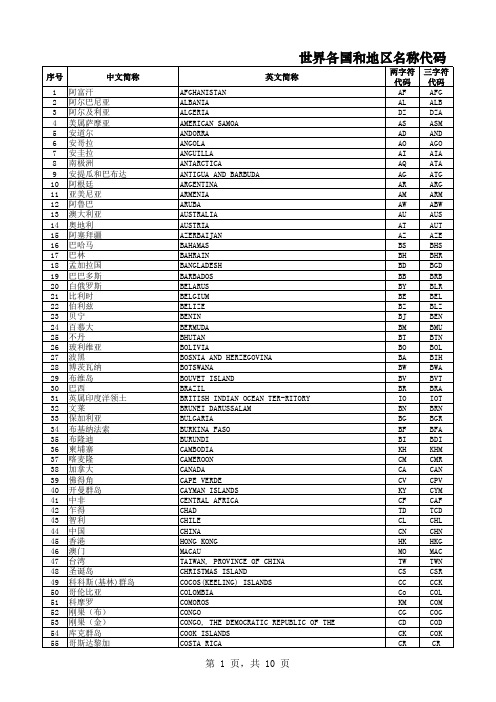
三字符 代码 AFG ALB DZA ASM AND AGO AIA ATA ATG ARG ARM ABW AUS AUT AZE BHS BHR BGD BRB BLR BEL BLZ BEN BMU BTN BOL BIH BWA BVT BRA IOT BRN BGR BFA BDI KHM CMR CAN CPV CYM CAF TCD CHL CHN HKG MAC TWN CSR CCK COL COM COG COD COK CR
英文简称
PERU PHILIPPINES PITCAIRN ISLANDS GROUP POLAND PORTUGAL PUERTO RICO QATAR REUNION ROMANIA RUSSIAN FEDERATION RWANDA SAINT HELENA SAINT KITTS AND NEVIS SAINT LUCIA SAINT PIERRE AND MIQUELON SAINT VINCENT AND THE GRENADINES SAMOA SAN MARION SAO TOME AND PRINCIPE SAUDI ARABIA SENEGAL SEYCHELLS SIERRA LEONE SINGAPORE SLOVAKIA SLOVENIA SOLOMON ISLANDS SOMALIA SOUTH AFRICA SOUTH GEORGIA AND SOUTH SANDWICH ISLANDS SPAIN SRI LANKA SUDAN SURINAME SVALBARD AND JAN MAYEN ISLANDS SWAZILAND SWEDEN SWITZERLAND SYRIA TAJIKISTAN TANZANIA THAILAND TOGO TOKELAU TONGA TRINIDAD AND TOBAGO TUNISIA TURKEY TURKMENISTAN TURKS AND CAICOS ISLANDS TUVALU UGANDA UKRAINE UNITED ARAB EMIRATES UNITED KINGDOM UNITED STATES UNITED STATES MINOR OUTLYING ISLANDS
两位三位字母组合的全球国名缩写英文大全
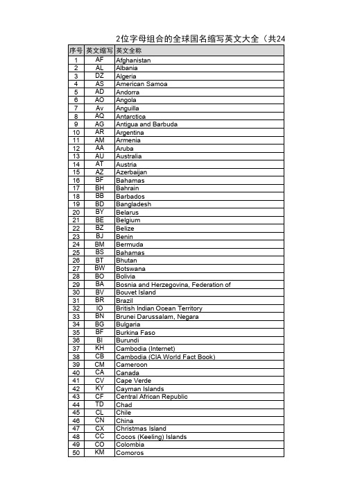
英文中文代 码AAfghanistan阿富汗AFG Albania阿尔巴尼亚ALB Algeria阿尔及利亚DZA American Samoa美属萨摩亚ASM Andorra安道尔AND Angola安哥拉AGO Anguilla安圭拉AIA Antarctica南极洲ATA Antigua and Barbuda安提瓜和巴布达岛ATG Argentina阿根廷ARG Armenia亚美尼亚ARM Aruba阿鲁巴岛ABW Australia澳大利亚AUS Austria奥地利AUT Azerbaijan阿塞拜疆AZEBBahamas巴哈马BHS Bahrain巴林BHR Bangladesh孟加拉国BGD Barbados巴巴多斯BRB Belarus BLR Belgium比利时BEL Belize伯利兹BLZ Benin贝宁BEN Bermuda百慕大BMU Bhutan不丹BTN Bolivia玻利维亚BOL Bosnia and Herzegovina波斯尼亚和墨塞哥维那BIH Botswana博茨瓦纳BWA Bouvet Island布韦岛BVT Brazil巴西BRA British Indian Ocean Territory英属印弟安海城IOT British Virgin Islands英属维尔京群岛VGB Brunei文莱BRN Bulgaria保加利亚BGR Burkina Faso BFA Burundi布隆迪BDICCambodia柬埔寨KHM Cameroon喀麦隆CMR Canada加拿大CAN Cape Verde佛得角群岛CPV Cayman Islands开曼群岛CYM Central African Republic中非共和国CAF Chad乍得TCD Chile智利CHLChina中国CHN Christmas Island (Australia)圣诞岛CXRCocos(Keeling)Islands科科斯群岛CCK Colombia哥伦比亚COL Comoros科摩罗COM Congo刚果COG Cook Islands库克群岛COK Costa Rica哥斯达黎加CRI Cote d Ivoire象牙海岸CIV Croatia克罗地亚HRV Cuba古巴CUB Cyprus塞浦路斯CYP Czechoslovakia捷克斯洛伐克CSKDDemocratic People's Republic of Korea朝鲜民主主义人民共和国PRK Denmark丹麦DNK Djibouti吉布提DJI Dominica多米尼加DMA Dominican Republic多米尼加共和国DOM EEast Timor东帝汶TMP Ecuador厄瓜多尔ECU Egypt埃及EGY El Salvador萨尔瓦多SLV Equatorial Guinea赤道几内亚GNQ Estonia爱沙尼亚EST Ethiopia埃寒俄比亚ETH FFalkland Islands (Malvinas)福克兰FLK Faroe Islands法罗群岛FRO Fiji斐济FJI Finland芬兰FIN France法国FRA French Guiana法属圭亚那GUF French Polynesia法属波利尼西亚PYF French Southern Territories ATF GGabon加蓬GAB Gambia冈比亚GMB Georgia格鲁吉亚GEO Germany德国DEU Ghana加纳GHA Gibraltar直布罗陀GIB Greece希腊GRC Greenland格陵兰岛GRL Grenada格林纳达GRDGuadeloupe瓜德罗普GLP Guam关岛GUM Guatemala危地马拉GTM Guinea几内亚GIN Guinea Bissau几内亚比绍GNB Guyana圭亚那GUYHHaiti海地HTI Heard and Mc Donald Islands HMD Honduras洪都拉斯HND Hong Kong中国香港HKG Hungary匈牙利HUNIIceland冰岛ISL India印度IND Indonesia印度尼西亚IDN Iran伊朗IRN Iraq伊拉克IRQ Ireland爱尔兰IRL Israel以色列ISR Italy意大利ITA JJamaica牙买加JAM Japan日本JPN Jordan约旦JOR KKazakhstan哈萨克斯坦KAZ Kenya肯尼亚KEN Kiribati基里巴斯KIR Korea, Repubiic of韩国KOR Kuwait科威特KWT Kyrgyzstan KGZ LLao People's Democratic Republic老挝民主主义人民共和国LAO Latvia拉脱维亚LVA Lebanon黎巴嫩LBN Lesotho莱索托LSO Liberia利比里亚LBR Libyan Arab Jamahiriya LBY Liechtenstein列支教士登LIE Lithuania立陶宛LTU Luxemburg卢森堡LUX MMacau马考MACMadagascar马达加斯加MDG Malawi马拉维MWI Malaysia马来西亚MYS Maldives马尔代夫MDV Mali马里MLI Malta马耳他MLT Marshall Islands马歇尔群岛MHL Martinique马提尼克MTQ Mauritania毛里塔尼亚MRT Mauritius毛里求斯MUS Mexico墨西哥MEX Micronesia密克罗尼西尼群岛FSM Moldova, Republic of 摩尔多瓦MDA Monaco摩纳哥MCO Mongolia蒙古MNG Montserrat蒙塞拉特山 MSR Morocco摩洛哥MAR Mozambique莫桑比克MOZ Myanmar MYA NNamibia纳米比亚NAM Nauru瑙鲁NRU Nepal尼泊尔NPL Netherlands荷兰NLD Netherlands Antilles荷属安的列斯群岛ANT Neutral Zone中立区NTZ New caledonia新喀里多尼亚岛NCL New Zealand新西兰NZL Nicaragua尼加拉瓜NIC Niger尼日尔NER Nigeria尼日利亚NGA Niue纽埃NIU Norfolk Island诺福克群岛NFK Northern Mariana Islands北马里亚纳群岛MNP Norway挪威NOR OOman阿曼OMN PPakistan巴基斯坦PAK Palau帕劳PLW Panama巴拿马PAN Papua New Guinea巴布亚新几内亚PNG Paraguay巴拉圭PRY Peru秘鲁PER Philippines菲律宾PHL Pitcairn Islands皮特凯恩群岛PCN Poland波兰POL Portugal葡萄牙PRT Puerto Rico波多黎各PRIQQatar卡塔尔QAT RReunion留尼汪REU Romania罗马尼亚ROM Russian Federation俄罗斯联邦RUS Rwanda卢旺达RWA SSaint Helena圣赫勒拿SHN Saint Kitts and Nevis圣基茨和尼维斯KNA Saint Lucia圣卢西亚LCA Saint Pierre and Miquelon圣皮埃尔和密克隆岛SPM Saint Vincent and the Grenadines圣文森特和格林纳丁斯VCT Samoa萨摩亚WSM San Marino圣马力诺SMR Sao Tome e Principe圣多美和普林西比STP Saudi Arabia沙特阿拉伯SAU Senegal塞内加尔SEN Seychelles塞舌尔SYC Sierra Leone塞拉利昂SLE Singapore新加坡SGP Slovenia斯洛文尼亚SVN Solomon Islands所罗门群岛SLB Somalia索马里SOM South Africa南非ZAF Spain西班牙ESP Sri Lanka斯里兰卡LKA Sudan苏丹SDN Surinam苏里南SUR Svalbard and Jan Mayen Islands斯瓦巴德和扬马延岛SJM Swaziland斯威士兰SWZ Sweden瑞典SWE Switzerland瑞士CHE Syrian Arab Republic叙利亚阿拉伯共和国SYR TTaiwan, Province of China中国台湾省TWN Tajikistan塔吉克斯坦TJK Tanzania坦桑尼亚TZA Thailand泰国THA Togo多哥TGO Tokelau托克劳群岛TKL Tonga汤加TON Trinidad and Tobago特立尼达和多巴哥TTO Tunisia突尼斯TUN Turkey土耳其TUR Turkmenistan土库曼斯坦TKMTurks and Caicos Islands特克斯和凯科斯群岛TCA Tuvalu图瓦卢TUV UUganda乌干达UGA Ukraine乌克兰UKR United Arab Emirates阿拉伯联合酋长国ARE United Kingdom英国GBR United States Misc. Pacific Islands米西太平洋群岛UMI United States of America美国USA Uruguay乌拉圭URY Uzbekistan乌兹别克斯坦UZB VVanuatu瓦努阿图VUT Vatican City State梵蒂冈VAT Venezuela委内瑞拉VEN Viet Nam越南VNM Virgin Islands(US)美属维尔京群岛VIR WWallis and Fortuna Islands沃利斯和帕图那岛WLS Western Sahara西撒哈拉ESH YYemen, Republic of 也门共和国YEM ZZaire扎伊尔ZAR Zambia赞比亚ZMB Zimbabwe津巴布韦ZWE[求助] LEN在公式里是什么意思啊LEN 返回文本字符串中的字符数。
MMSZ5256资料
Cathode Mark
.152 (3.85) .140 (3.55) .112 (2.85) .100 (2.55)
Top View
max. .004 (0.1)
max. .053 (1.35)
min. .010 (0.25)
max. .006 (0.15)
.067 (1.70) .055 (1.40)
1/20/99
元器件交易网
MMSZ5225 THRU MMSZ5267
ELECTRICAL CHARACTERISTICS
Ratings at 25°C ambient temperature unless otherwise specified.
Type
Marking Code
1.0 1.0 1.0 1.0 1.0 2.0 2.0 3.0 3.5 4.0 5.0 6.0 6.5 6.5 7.0 8.0 8.4 9.1 9.9 10 11 12 13 14 14 15 17 18 19 21 21 23 25 27 30 33 36 39 43 46 47 52 56
NOTES: (1) The Zener Impedance is derived from the 1kHz AC voltage which results when an AC current having an RMS value equal to 10% of the Zener current (IZT or IZK) is superimposed on IZT or IZK. Zener Impedance is measured at two points to insure a sharp knee on the breakdown curve and to eliminate unstable units. (2) Measured with device junction in thermal equilibrium.
方正书版排版注解命令列表
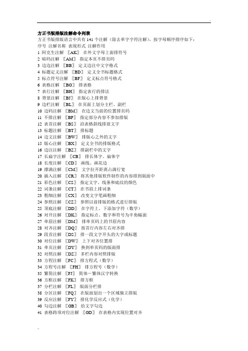
方正书版排版注解命令列表方正书版排版语言中共有141个注解(除去单字字符注解),按字母顺序排序如下:序号注解名称表现形式注解作用1 阿克生注解〖AK〗在外文字母上面排符号2 暗码注解〖AM〗指定本页不排页码3 边边注解〖BB〗定义边注中文字格式4 标题定义注解〖BD〗定义全书标题格式5 标点符号注解〖BF〗定义标点符号格式6 表格注解〖BG〗排表格7 表行注解〖BH〗指定表行的排法8 背景注解〖BJ〗在版心上排背景9 边栏注解〖BL〗在页面上划分主栏、副栏10 边码注解〖BM〗在边文当前的位置排页码11 不排注解〖BP〗指定部分内容不参加排版12 表首注解〖BS〗沿表格斜线排放文字13 标题注解〖BT〗排标题14 边文注解〖BW〗排版心之外的文字15 版心注解〖BX〗定义全书的排版格式16 边注注解〖BZ〗排副栏中的文字17 长扁字注解〖CB〗排长体字、扁体字18 长度注解〖CD〗画线、画花边19 撑满注解〖CM〗文字拉开距离占满行宽20 插入注解〖CR〗将其他排版软件制作的内容排到版面中21 彩色注解〖CS〗指定文字、线条和底纹的颜色22 词条注解〖CT〗在书眉上排词条23 粗细注解〖CX〗改变文字笔画粗细24 参照注解〖CZ〗参照以前排版的格式进行排版25 顶底注解〖DD〗在字符上、下添加字符(数学)26 对开注解〖DK〗指定标点、数字和符号为半角幅面27 单眉注解〖DM〗排单页码上的书眉内容28 对齐注解〖DQ〗按首行内容左右对齐排29 段首注解〖DS〗排一段文字开头的大字或标题30 对位注解〖DW〗上下对齐位置排31 单页注解〖DY〗换到单页码的版面排32 对照注解〖DZ〗多栏内容对照排版33 方程注解〖FC〗排方程式(数学)34 方程号注解〖FH〗排方程号(数学)35 繁简注解〖FJ〗简体-繁体汉字转换36 方框注解〖FK〗排方框37 分栏注解〖FL〗版面分栏排38 分区注解〖FQ〗在版面划出一个区域独立排版39 反应注解〖FY〗排化学反应式(化学)40 勾边注解〖GB〗给文字勾边41 表格跨项对位注解〖GD〗在表格内实现位置对齐42 改宽注解〖GK〗改变当前行宽43 改排注解〖GP〗竖排表格文字44 表格跨项位标注解〖GW〗在表格内设置位置标记45 割注注解〖GZ〗排古籍图书中的随文注解46 行距注解〖HJ〗改变行间距离47 行宽注解〖HK〗改变字行宽度48 行列注解〖HL〗排数字行列式(数字)49 行齐注解〖HQ〗外文行末是否对齐排50 行数注解〖HS〗指定标题所占行数51 汉体注解〖HT〗指定汉字字体与字号52 画线注解〖HX〗在版面上画线53 行移注解〖HY〗严格规定两行之间的距离54 行中注解〖HZ〗在多行文字的中线上排字55 界标注解〖JB〗在盒组左、右加分界符号(数字)56 加底注解〖JD〗排底纹57 结构注解〖JG〗进入排化学结构式状态(化学)58 角键注解〖JJ〗排环结构式的化学键(化学)59 紧排注解〖JP〗压缩字与字之间的距离60 基线注解〖JX〗移动文字的基线61 居右注解〖JY〗文字靠右排62 居中注解〖JZ〗文字排在行中间63 外挂字体别名定义注解〖KD〗指定外挂字体的别名64 开方注解〖KF〗排数字根式(数字)65 空格注解〖KG〗字间加空66 空行注解〖KH〗行间加空67 空眉注解〖KM〗本页不排书眉68 空心注解〖KX〗排空心文字69 邻边注解〖LB〗六角环之间互相连接(化学)70 连到注解〖LD〗字键连接点(化学)71 六角环注解〖LJ〗排六角环(化学)72 另栏注解〖LL〗转排下一栏73 另面注解〖LM〗换到另一面排74 另区注解〖LQ〗图片连同相关文字转排到下一页75 相联始点注解〖LS〗化学式连线始点(化学)76 立体注解〖LT〗排立体文字77 相联终点注解〖LZ〗化学式连线始点(化学)78 自动目录定义注解〖MD〗定义目录格式79 目录注解〖ML〗目录登记80 眉眉注解〖MM〗排单页、双页书眉上相同的内容81 多页分区注解〖MQ〗连续多页重复分区82 书眉说明注解〖MS〗书眉说明83 民体注解〖MT〗定义民族文字体84 自动目录登记注解〖MZ〗自动抽取目录内容85 页号注解〖PN〗排特殊页码86 插入EPS注解〖PS〗插入EPS文件87 拼音注解〖PY〗排汉语拼音88 前后注解〖QH〗改变行宽并撑满行89 全身注解〖QS〗字母、数字和标点符号排全角90 倾斜注解〖QX〗字符倾斜排91 日文注解〖RW〗指定输出日文新、旧字形92 书版注解〖SB〗指定同时排版的小样文件名93 始点注解〖SD〗排版的起始点94 段首缩进注解〖SJ〗段首缩进排95 双眉注解〖SM〗排双页码面的书眉内容96 竖排注解〖SP〗竖排化学式(化学)97 上齐注解〖SQ〗上边对齐(取消上下居中)98 角标大小设置注解〖SS〗改变角标字大小99 数字字体注解〖ST〗改变数字字体100 数字字体注解〖ST+〗数字字体与汉字字体自动搭配101 上下注解〖SX〗排分式(数字)102 双页注解〖SY〗转到双码页上排103 数字注解〖SZ〗竖排时数字单个直立排104 条码注解〖TP〗提取条码元素数据105 图片注解〖TP〗排插图图片106 图说注解〖TS〗排图片说明文字107 添线注解〖TX〗在盒子上、下添加线或符号108 条码注解〖TM〗提取条码元素数据109 图文注解〖TW〗指定图片说明文字的属性110 位标注解〖WB〗指定对齐位置的标记111 无页码注解〖WM〗本页不排页码,也不占位置112 外文字体注解〖WT〗改变外文字体113 外体自动搭配注解〖WT〗实现外文与汉字字体自动搭配114 外文注解〖WW〗使用外文标点符号115 无线表注解〖WX〗排无线表116 文种注解〖WZ〗选择所排外文的种类117 消除单字行注解〖XD〗消除单字行118 插入随文图片注解〖XC〗插入随文图片119 线字号注解〖XH〗指定线粗细120 相联注解〖XL〗排反应式上下附加线及字符(化学)121 线末注解〖XM〗结构式连线末端(化学)122 索引点注解〖XP〗抽取索引内容123 线始注解〖XS〗结构式连线始端(化学)124 斜线注解〖XX〗画斜线125 旋转注解〖XZ〗旋转汉字与字符126 页码注解〖YM〗指定页码格式127 右旋注解〖YX〗右旋注解(蒙文数学、化学)128 阴阳字注解〖YY〗汉字与字符为黑底白字129 子表注解〖ZB〗表格内再套表格130 自定义注解〖ZD〗定义宏注解简化重复内容131 自换注解〖ZH〗指定自动换行位置132 字键注解〖ZJ〗排化学键(化学)133 自控注解〖ZK〗自动换行后缩进排134 自定义文件名注解〖ZM〗指定自定义文件名135 左齐注解〖ZQ〗公式左端排文字(数字)136 注文说明注解〖ZS〗指定注释的格式137 整体注解〖ZT〗指定一段文字内容不可拆页138 注文注解〖ZW〗排注释的内容139 左旋注解〖ZX〗排蒙文其主体语言为中文时,蒙文单词竖排140 注音注解〖ZY〗指定注音字符的排法141 着重注解〖ZZ〗对字符加着重符号。
MMSZ5231中文资料
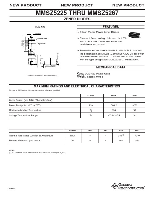
NEW PRODUCT
NEW PRODUCT
MMSZ5225 THRU MMSZ5267
ZENER DIODES
SOD-123
.022 (0.55)
FEATURES
♦ Silicon Planar Power Zener Diodes ♦ Standard Zener voltage tolerance is ± 5% with a “B” suffix. Other tolerances are available upon request. ♦ These diodes are also available in Mini-MELF case with the designation ZMM5225 ... ZMM5267, DO-35 case with type designation 1N5225 ... 1N5267 and SOT-23 case with the type designation MMBZ5225 ... MMBZ5267.
(%/K)
IR (µA)
Test Voltage VR (V)
MMSZ5225 MMSZ5226 MMSZ5227 MMSZ5228 MMSZ5229 MMSZ5230 MMSZ5231 MMSZ5232 MMSZ5233 MMSZ5234 MMSZ5235 MMSZ5236 MMSZ5237 MMSZ5238 MMSZ5239 MMSZ5240 MMSZ5241 MMSZ5242 MMSZ5243 MMSZ5244 MMSZ5245 MMSZ5246 MMSZ5247 MMSZ5248 MMSZ5249 MMSZ5250 MMSZ5251 MMSZ5252 MMSZ5253 MMSZ5254 MMSZ5255 MMSZ5256 MMSZ5257 MMSZ5258 MMSZ5259 MMSZ5260 MMSZ5261 MMSZ5262 MMSZ5263 MMSZ5264 MMSZ5265 MMSZ5266 MMSZ5267
MMSZ5232BT1中文资料
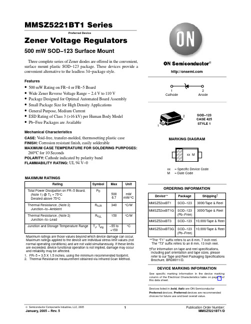
MMSZ5221BT1 SeriesPreferred DeviceZener Voltage Regulators 500 mW SOD−123 Surface MountThree complete series of Zener diodes are offered in the convenient, surface mount plastic SOD−123 package. These devices provide a convenient alternative to the leadless 34−package style.Features•500 mW Rating on FR−4 or FR−5 Board•Wide Zener Reverse V oltage Range − 2.4 V to 110 V •Package Designed for Optimal Automated Board Assembly •Small Package Size for High Density Applications •General Purpose, Medium Current•ESD Rating of Class 3 (>16 kV) per Human Body Model•Pb−Free Packages are AvailableMechanical CharacteristicsCASE:V oid-free, transfer-molded, thermosetting plastic case FINISH:Corrosion resistant finish, easily solderableMAXIMUM CASE TEMPERATURE FOR SOLDERING PURPOSES: 260°C for 10 SecondsPOLARITY:Cathode indicated by polarity band FLAMMABILITY RATING:UL 94 V−0MAXIMUM RATINGSMaximum ratings are those values beyond which device damage can occur. Maximum ratings applied to the device are individual stress limit values (not normal operating conditions) and are not valid simultaneously. If these limits are exceeded, device functional operation is not implied, damage may occur and reliability may be affected.1.FR−5 = 3.5 X 1.5 inches, using the minimum recommended footprint.2.Thermal Resistance measurement obtained via infrared Scan Method.See specific marking information in the device marking column of the Electrical Characteristics table on page 3 of this data sheet.DEVICE MARKING INFORMATIONDevices listed in bold, italic are ON Semiconductor Preferred devices. Preferred devices are recommended choices for future use and best overall value.ELECTRICAL CHARACTERISTICS (T A = 25°C unlessotherwise noted, V= 0.95 V Max. @ I = 10 mA)4.Nominal Zener voltage is measured with the device junction in thermal equilibrium at T L = 30°C $1°C.5.Z ZT and Z ZK are measured by dividing the AC voltage drop across the device by the ac current applied.The specified limits are for I Z(AC) = 0.1 I Z(dc) with the AC frequency = 1 KHz.V Z , NOMINAL ZENER VOLTAGE (V)−1012345678Figure 1. Temperature Coefficients (Temperature Range −55°C to +150°C)100101V Z , NOMINAL ZENER VOLTAGE (V)Figure 2. Temperature Coefficients (Temperature Range −55°C to +150°C)1.21.00.80.60.40.20T, TEMPERATURE (°C)Figure 3. Steady State Power Derating PW, PULSE WIDTH (ms)Figure 4. Maximum Nonrepetitive Surge Power1000100101V Z , NOMINAL ZENER VOLTAGEFigure 5. Effect of Zener Voltage onZener Impedance100101V F , FORWARD VOLTAGE (V)Figure 6. Typical Forward Voltage1000100101q V Z , T E M P E R A T U R E C O E F F I C I E N T (m V /°C )q V Z , T E M P E R A T U R E C O E F F I C I E N T (m V /°C )P p k , P E A K S U R G E P O W E R (W A T T S )Z Z T , D Y N A M I C I M P E D A N C E (W )I F , F O R W A R D C U R R E N T (m A )C , C A P A C I T A N C E (p F )V Z , NOMINAL ZENER VOLTAGE (V)Figure 7. Typical Capacitance 1000100101V Z , ZENER VOLTAGE (V)1001010.10.01V Z , ZENER VOLTAGE (V)1001010.10.01V Z , NOMINAL ZENER VOLTAGE (V)Figure 8. Typical Leakage CurrentFigure 9. Zener Voltage versus Zener Current(V Z Up to 12 V)Figure 10. Zener Voltage versus Zener Current(12 V to 91 V)I R , L E A K A G E C U R R E N T (m A )I Z , Z E N E R C U R R E N T (m A )I Z , Z E N E R C U R R E N T (m A )PACKAGE DIMENSIONSSOD−123CASE 425−04ISSUE Cǒmm inchesǓSCALE 10:1*For additional information on our Pb−Free strategy and solderingdetails, please download the ON Semiconductor Soldering and Mounting Techniques Reference Manual, SOLDERRM/D.SOLDERING FOOTPRINT*ON Semiconductor and are registered trademarks of Semiconductor Components Industries, LLC (SCILLC). SCILLC reserves the right to make changes without further notice to any products herein. SCILLC makes no warranty, representation or guarantee regarding the suitability of its products for any particular purpose, nor does SCILLC assume any liability arising out of the application or use of any product or circuit, and specifically disclaims any and all liability, including without limitation special, consequential or incidental damages.“Typical” parameters which may be provided in SCILLC data sheets and/or specifications can and do vary in different applications and actual performance may vary over time. All operating parameters, including “Typicals” must be validated for each customer application by customer’s technical experts. SCILLC does not convey any license under its patent rights nor the rights of others. SCILLC products are not designed, intended, or authorized for use as components in systems intended for surgical implant into the body, or other applications intended to support or sustain life, or for any other application in which the failure of the SCILLC product could create a situation where personal injury or death may occur. Should Buyer purchase or use SCILLC products for any such unintended or unauthorized application, Buyer shall indemnify and hold SCILLC and its officers, employees, subsidiaries, affiliates,and distributors harmless against all claims, costs, damages, and expenses, and reasonable attorney fees arising out of, directly or indirectly, any claim of personal injury or death associated with such unintended or unauthorized use, even if such claim alleges that SCILLC was negligent regarding the design or manufacture of the part. SCILLC is an Equal Opportunity/Affirmative Action Employer. This literature is subject to all applicable copyright laws and is not for resale in any manner.PUBLICATION ORDERING INFORMATION。
MMSZ6V2中文资料

POWER: 0.5 Wa t VOLTAGE RANGE: 2.4 - 7 5VMMSZ2V4 - MMSZ75SymbolValueUnitTotal Power Dissipation on FR-5 Board,P DmW(Note 1), at T L = 75 °Derated above 75 °C6.7mW/°C Thermal Resistance Junction to Ambient R ӨJA 340°C/W Thermal Resistance Junction to Lead R ӨJL150°C/W Junction Temperature Range T J -55 to + 150°C Storage Temperature RangeT STG-55 to + 150°CNote :(1) FR-5 = 3.5 x 1.5 inchesParameterFeaturesSmall Package Size for High Density Applications!!!!Total Power Dissipation 500 mW on FR-4or FR-5 BoardWide Zener Reverse Voltage Range 2.4 Vto 75 VPackage Designed for Optimal AutomatedBoard AssemblyC 500SURFACE MOUNT SILICON ZENER DIODES: SOD-123FLplastic body over passivated junction Method 2026: Color band denotes cathode end : AnyCase Terminals Polarity Mounting Position : Plated axial leads,solderable per MIL-STD-750,Mechanical Data!!!!!!Weight:0.0007 ounce, 0.02 grams3.58 3.72 0.55 0.57 0.530.15 0.17 0.13E D 1.00 1.03 0.097 1.05 1.08 1.021 1.80 1.83 1.77 2.75 2.78 2.72A 3.653 SOD-123FLDim Min Max Typ B C H L All Dimensions in mmMaximum Ratings T A = 25°C unless otherwise specified MMSZ6V2MMSZ6V2ELECTRICAL CHARACTERISTICS (Ta = 25 °C unless otherwise note, V F= 0.9 Vmax. @ I F= 10 mA)ZZT1 (3)Z ZT2 (3)Max. Reverse @ I ZT1 = @ I ZT2 =Leakage 5 mA 1 mA Current MinNom Max Min Max (μA)(V)2.28 2.4 2.52100 1.7 2.160050 1.02.57 2.7 2.84100 1.9 2.460020 1.02.85 3.0 3.1595 2.1 2.760010 1.03.14 3.3 3.4795 2.3 2.9600 5.0 1.03.42 3.6 3.7890 2.7 3.3600 5.0 1.03.71 3.9 4.1090 2.9 3.5600 3.0 1.04.09 4.3 4.5290 3.3 4.0600 3.0 1.04.47 4.7 4.9480 3.7 4.7500 3.0 2.04.85 5.1 5.3660 4.2 5.3480 2.0 2.05.32 5.6 5.8840 4.8 6.0400 1.0 2.05.89 6.2 6.5110 5.6 6.6150 3.0 4.06.46 6.87.1415 6.37.280 2.0 4.07.137.57.8815 6.97.980 1.0 5.07.798.28.61157.68.7800.7 5.08.659.19.56158.49.61000.5 6.09.501010.50209.310.61500.27.010.451111.552010.211.61500.18.011.401212.602511.212.71500.18.012.351313.653012.314.01700.18.014.251515.753013.715.52000.0510.515.201616.804015.217.02000.0511.217.101818.904516.719.02250.0512.619.002021.005518.721.12250.0514.020.902223.105520.723.22500.0515.422.802425.207022.725.52500.0516.8Notes :(1) The type number shown have a standard tolerance of±5% on the nominal Zener Voltage.(2) Tolerance and Voltage Designation: Zener Voltage (V Z ) is measured with the Zener Current applied for PW = 1ms.(3) Z ZT and Z ZK are measured by dividing the AC voltage drop across the device by the AC current applied. The specified limits are for I Z(AC)=0.1I Z(DC), with the AC frequency = 1 kHz.V Z1(1, 2)V Z2 (1, 2)(Ω)I R @ V R @ I ZT1 = 5 mA@ I ZT2 = 1 mA(V)(Ω)(V)TYPEMMSZ2V4 MMSZ2V7 MMSZ3V0 MMSZ3V3 MMSZ3V6 MMSZ3V9 MMSZ4V3 MMSZ4V7 MMSZ5V1 MMSZ5V6 MMSZ6V2 MMSZ6V8 MMSZ7V5 MMSZ8V2 MMSZ9V1 MMSZ10 MMSZ11 MMSZ12 MMSZ13 MMSZ15 MMSZ16 MMSZ18 MMSZ20 MMSZ22 MMSZ24MMSZ6V2MMSZ6V2ELECTRICAL CHARACTERISTICS (Ta = 25 °C unless otherwise note, V F= 0.9 Vmax. @ I F= 10 mA)Z ZT1(3)Z ZT2 (3)Max. Reverse @ I ZT1 = @ I ZT2 =Leakage TYPE NO.2 mA0.5 mA Current MinNom Max Min Max (μ25.652728.358025.028.93000.0518.928.503031.508027.832.03000.0521.031.353334.658030.835.03250.0523.134.203637.809033.838.03500.0525.237.053940.9513036.741.03500.0527.340.854345.1515039.746.03750.0530.144.654749.3517043.750.03750.0532.948.455153.5518047.654.04000.0535.753.205658.8020051.560.04250.0539.258.006266.00200---0.24764.006872.00250---0.25270.007579.00300---0.257Notes :(1) The type number shown have a standard tolerance of ±5% on the nominal Zener Voltage.(2) Tolerance and Voltage Designation: Zener Voltage (V Z ) is measured with the Zener Current applied for PW = 1ms.(3) Z ZT and Z ZK are measured by dividing the AC voltage drop across the device by the AC current applied. The specified limits are for I Z(AC)=0.1I Z(DC), with the AC frequency = 1 kHz.(Ω)I R @ V R V Z1(1, 2)V Z2 (1, 2)@ I ZT1 ZT2 = 0.1 mA(V)(Ω)(V) MMSZ27 MMSZ30 MMSZ33 MMSZ36 MMSZ39 MMSZ43 MMSZ47 MMSZ51 MMSZ56 MMSZ62 MMSZ68 MMSZ75= 2 mA@ I MMSZ6V2MMSZ6V2。
世界各大洲国家中英文、区号、首都大全

乌克兰
基辅 Kiev
+380
乌克兰语
AT
Austria
奥地利
维也纳 Vienna
+43
德语
PL
Poland
波兰
华沙 Warsaw
+48
波兰语
DE
Germany
德国
柏林 Berlin
+49
德语
CZ
Czech Republic
捷克共和国
布拉格 Prague
+420
捷克语
LI
Liechtenstein
列支敦士登
文莱达鲁萨兰国
斯里巴加湾Bandar Seri Begawan
+673
马来语
VN
Vietnam
越南
河内 Hanoi
+84
越南语
TP
East Timor
东帝汶
帝力 Dili
+670
德顿语
SG
Singapore
新加坡
新加坡 Singapore
+65
英语
ID
Indonesia
印度尼西亚
雅加达 Jakarta
RW
Rwanda
卢旺达
BI
Burundi
布隆迪
SC
Seychelles
塞舌尔
ER
Eritrea
厄立特里亚
TD
Chad
乍得
CF
Central African Republic
中非共和国
EQ
Equatorial Guinea
赤道几内亚
CM
Cameroon
MMSZ4707中文资料

MAXIMUM RATINGS AND ELECTRICAL CHARACTERISTICS
Ratings at 25°C ambient temperature unless otherwise specified.
SYMBOL
VALUE
UNIT
Zener Current (see Table “Characteristics”) Power Dissipation at TL = 75°C Maximum Junction Temperature Storage Temperature Range Ptot Tj TS 500(1) 150 -55 to +150 mW °C °C
2.00 1.00 0.80 7.50 7.50 5.00 4.00 10.0 10.0 10.0 10.0 10.0 10.0 1.00 1.00 1.00 1.00 0.05 0.05 0.05 0.05 0.05 0.05 0.05 0.05 0.05 0.01 0.01 0.01 0.01 0.01 0.01 0.01 0.01 0.01 0.01 0.01
2.52 2.84 3.15 3.47 3.78 4.10 4.52 4.94 5.36 5.88 6.51 7.14 7.88 8.61 9.14 9.56 10.5 11.6 12.6 13.7 14.7 15.8 16.8 17.9 18.9 20.0 21.0 23.1 25.2 26.3 28.4 29.4 31.5 34.7 37.8 41.0 45.2
NOTES: (1) Measured with device junction in thermal equilibrium
Test Voltage VR (Volts)
BZX84C3V9V中文资料
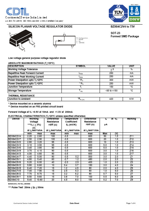
SILIICON PLANAR VOLTAGE REGULATOR DIODEBZX84C2V4 to 75V SOT-23Formed SMD PackageLow voltage general purpose voltage regulator diode ABSOLUTE MAXIMUM RATINGS (T a =25°C)UNIT %Repetitive Peak Forward Current mA Repetitive Peak Working Current mA mW mW °C °CTHERMAL RESISTANCE K/W* Device mounted on a ceramic alumna** Device mounted on an FR5 printed circuit boardELECTRICAL CHARACTERISTICS (T a =25°C unless specified otherwise) Device Temperature DifferentialI R at V RMarkingCoefficient ResistanceS Z (mV/K)rdiff (Ω)µAat I Z test=5mA at I Z test=1mAmin max min max max Max (V)BZX84C2V4 2.20 2.60 -3.560050 1.0Z11BZX84C2V72.50 2.90 -3.560020 1.0Z12BZX84C3V0 2.80 3.20 -3.560010 1.0Z13BZX84C3V3 3.10 3.50 -3.5600 5.0 1.0Z14BZX84C3V6 3.40 3.80 -3.5600 5.0 1.0Z15BZX84C3V9 3.70 4.10-3.56003.0 1.0Z16BZX84C4V34.00 4.60 -3.5600 3.0 1.0Z17BZX84C4V7 4.40 5.00 -3.5 0.2500 3.0 2.0Z1BZX84C5V1 4.80 5.40 -2.7 1.2480 2.0 2.0Z2BZX84C5V6 5.20 6.00 -2.0 2.5400 1.0 2.0Z3BZX84C6V2 5.80 6.60 0.4 3.7150 3.0 4.0Z4BZX84C6V8 6.407.20 1.2 4.580 2.0 4.0Z5BZX84C7V57.007.90 2.5 5.380 1.0 5.0Z6BZX84C8V27.708.70 3.2 6.2800.7 5.0Z7BZX84C9V18.509.60 3.8 7.01000.5 6.0Z8BZX84C109.4010.604.5 8.01500.27.0Z9BZX84C2V4_75V Rev_060506E*** Pulse Test 20ms < tp < 50ms1515152060401015909090801001009595 + 5VALUE max I ZRM Storage Temperature T stg Junction to Ambient*R th (j-a)DESCRIPTIONI FRM Working Voltage Tolerance Power Dissipation upto T a =25ºC SYMBOL *P D ***V Z ( + 5%)(V)at I Z test=5mA Resistance rdiff (Ω)at I Z test=5mA250420300- 65 to +150250Forward Voltage at V F <0.9V at 10mA and <1.5V at 200mAVoltage 150250Differential Working Power Dissipation upto T c =25ºC **P D Junction Temperature T j Pin Configuration1 = A N ODE2 = N C3 =CATHODE12Continental Device India LimitedAn ISO/TS 16949, ISO 9001 and ISO 14001 Certified CompanySILIICON PLANAR VOLTAGE REGULATOR DIODEBZX84C2V4 to 75V SOT-23Formed SMD PackageELECTRICAL CHARACTERISTICS (T a =25°C unless specified otherwise) Device Temperature DifferentialI R at V RMarkingCoefficientResistanceS Z (mV/K)rdiff (Ω)µAat I Z test=5mAat I Z test=1mA min max min max max Max (V)BZX84C1110.4011.60 5.4 9.01500.18Y1BZX84C1211.4012.70 6.0 101500.18Y2BZX84C1312.4014.10 7.0 111700.18Y3BZX84C1513.8015.60 9.2 132000.0510.5Y4BZX84C1615.3017.10 10.4 142000.0511.2Y5BZX84C1816.8019.10 12.4 162250.0512.6Y6BZX84C2018.8021.20 14.4 182250.0514.0Y7BZX84C2220.8023.30 16.4 202500.0515.4Y8BZX84C2422.8025.60 18.4 222500.0516.8Y9at I Z Test=2mA at I Z Test=0.5mABZX84C2725.1028.90 21.4 25.33000.0518.9Y10BZX84C3028.0032.00 24.4 29.43000.0521.0Y11BZX84C3331.0035.00 27.4 33.43250.0523.1Y12BZX84C3634.0038.00 30.4 37.43500.0525.2Y13BZX84C3937.0041.00 33.4 41.23500.0527.3Y14BZX84C4340.0046.00 37.6 46.63750.0530.1Y15BZX84C4744.0050.00 42.0 51.83750.0532.9Y16BZX84C5148.0054.00 46.6 57.24000.0535.7Y17BZX84C5652.0060.00 52.2 63.84250.0539.2Y18BZX84C6258.0066.00 58.8 71.64500.0543.4Y19BZX84C6864.0072.00 65.6 79.84750.0547.6Y20BZX84C7570.0079.0073.4 88.65000.0552.5Y21BZX84C2V4_75V Rev_060506E*** Pulse Test 20ms < tp < 50ms2002152402551301501701808080908025303070at I Z test=5mA at I Z test=5mA max at I Z test=2mAat I Z Test=2mA4045555520Resistance ***V Z ( + 5%)rdiff (Ω)(V)Forward Voltage at V F <0.9V at 10mA and <1.5V at 200mAWorking Differential Voltage Pin Configuration1 = A N ODE2 = N C3 =CATHODE12BZX84C2V4 to 75V SOT-23Formed SMD PackageSOT-23 Package Reel InformationReel specification for W" Packing (13" reel)BZX84C2V4_75V Rev_060506ESOT-23 Formed SMD PackageTape Specification for SOT-23 Surface Mount DeviceS O T -23 T &R3K /reel 10K /reel136 g m /3K p c s 415 g m /10K p c s3" x 7.5" x 7.5"9" x 9" x 9"13" x 13" x 0.5"12 K 51 K 10 K17" x 15" x 13.5"19" x 19" x 19"17" x 15" x 13.5"192 K 408 K 300 K12 k g s 28 k g s 16 k g sPACKAGEN e t W e i g h t /Q t y DetailsS T A N D A R D PACKI N N E R C A R T O N B O XQ t y O U T E R C A R T O N B O XQ t y G r W t SizeSizePacking Detail±0.0114.47.9 – 10.9T R A I L E RF I X I N GT A P EL E A D E R9.2±0.5MAXNOTES:No. of Devices8mm Tape Size of Reel 330 mm (13")10,000 Pcs 8mm Tape Size of Reel 180 mm (7")3,000 Pcs1.The bandolier of 330 mm reel contains at least 10,000 devices.2.The bandolier of 180 mm reel contains at least 3,000 devices.3.No more than 0.5% missing devices / reel. 50 empty compartments for 330 mm reel.15 empty compartments for 180 mm reel.4.Three consecutive empty places might be found provided this gap is followed by 6 consecutive devices.5.The carrier tape (leader) starts with at least 75 empty positions (equivalent to 330 mm).In order to fix the carrier tape a self adhesive tape of 20 to 50 mm is applied. At the end of the bandolier at least 40 empty positions (equivalent to 160 mm) are there.3.15Customer Notes BZX84C2V4 to 75VSOT-23Formed SMD Package1. CDIL Semiconductor Devices are RoHS compliant, customers are requested to pleasedispose as per prevailing Environmental Legislation of their Country.2. In Europe, please dispose as per EU Directive 2002/96/EC on Waste Electrical andElectronic Equipment (WEEE).BZX84C2V4_75V Rev_060506E DisclaimerThe product information and the selection guides facilitate selection of the CDIL's Semiconductor Device(s)best suited for application in your product(s)as per your requirement.It is recommended that you completely review our Data Sheet(s)so as to confirm that the Device(s)meet functionality parameters for your application.The information furnished in the Data Sheet and on the CDIL Web Site/CD are believed to be accurate and reliable.CDIL however,does not assume responsibility for inaccuracies or incomplete information.Furthermore,CDIL does not assume liability whatsoever,arising out of the application or use of any CDIL product;neither does it convey any license under its patent rights nor rights of others. These products are not designed for use in life saving/support appliances or systems.CDIL customers selling these products(either as individual Semiconductor Devices or incorporated in their end products),in any life saving/support appliances or systems or applications do so at their own risk and CDIL will not be responsible for any damages resulting from such sale(s).CDIL strives for continuous improvement and reserves the right to change the specifications of its products without prior notice.CDIL is a registered Trademark ofContinental Device India LimitedC-120 Naraina Industrial Area, New Delhi 110 028, India.Telephone + 91-11-2579 6150, 4141 1112 Fax + 91-11-2579 5290, 4141 1119email@ 。
ZMM5222B中文资料
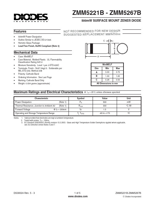
DS30024 Rev. 5 - 3
3 of 5
ZMM5221B-ZMM5267B
NOT RECOMMENDED FOR NEW DESIGN SUGGESTED REPLACEMENT MMSZ52xx
Ordering Information
Device ZMM5221B-7 ZMM5221B-13 ZMM5222B-7 ZMM5222B-13 ZMM5223B-7 ZMM5223B-13 ZMM5224B-7 ZMM5224B-13 ZMM5225B-7 ZMM5225B-13 ZMM5226B-7 ZMM5226B-13 ZMM5227B-7 ZMM5227B-13 ZMM5228B-7 ZMM5228B-13 ZMM5229B-7 ZMM5229B-13 ZMM5230B-7 ZMM5230B-13 ZMM5231B-7 ZMM5231B-13 ZMM5232B-7 ZMM5232B-13 ZMM5233B-7 ZMM5233B-13 ZMM5234B-7 ZMM5234B-13 ZMM5235B-7 ZMM5235B-13 ZMM5236B-7 ZMM5236B-13 ZMM5237B-7 ZMM5237B-13 ZMM5238B-7 ZMM5238B-13 ZMM5239B-7 ZMM5239B-13 ZMM5240B-7 ZMM5240B-13 ZMM5241B-7 ZMM5241B-13 ZMM5242B-7 ZMM5242B-13 ZMM5243B-7 ZMM5243B-13 ZMM5244B-7 ZMM5244B-13 ZMM5245B-7 ZMM5245B-13
Notes:
@ TA = 25°C unless otherwise specified Maximum Zener Impedance IZT Max (V) 2.52 2.63 2.84 2.94 3.15 3.47 3.78 4.10 4.52 4.94 5.36 5.88 6.30 6.51 7.14 7.88 8.61 9.14 9.56 10.50 11.55 12.60 13.65 14.70 15.75 16.80 17.85 18.90 19.95 21.00 23.10 25.20 26.25 28.35 29.40 31.50 34.65 37.80 40.95 45.15 49.35 53.55 58.80 63.00 65.10 71.40 78.75 mA 20 20 20 20 20 20 20 20 20 20 20 20 20 20 20 20 20 20 20 20 20 20 9.5 9.0 8.5 7.8 7.4 7.0 6.6 6.2 5.6 5.2 5.0 4.6 4.5 4.2 3.8 3.4 3.2 3.0 2.7 2.5 2.2 2.1 2.0 1.8 1.7 ZZT @ IZT W 30 30 30 30 29 28 24 23 22 19 17 11 7.0 7.0 5.0 6.0 8.0 8.0 10 17 22 30 13 15 16 17 19 21 23 25 29 33 35 41 44 49 58 70 80 93 105 125 150 170 185 230 270 ZZK @ IZK = 0.25mA W 1200 1250 1300 1400 1600 1600 1700 1900 2000 1900 1600 1600 1600 1000 750 500 500 600 600 600 600 600 600 600 600 600 600 600 600 600 600 600 600 600 600 600 700 700 800 900 1000 1100 1300 1400 1400 1600 1700 Maximum Reverse Current IR µA 100 100 75 75 50 25 15 10 5.0 5.0 5.0 5.0 5.0 5.0 3.0 3.0 3.0 3.0 3.0 3.0 2.0 1.0 0.5 0.1 0.1 0.1 0.1 0.1 0.1 0.1 0.1 0.1 0.1 0.1 0.1 0.1 0.1 0.1 0.1 0.1 0.1 0.1 0.1 0.1 0.1 0.1 0.1 @VR V 1.0 1.0 1.0 1.0 1.0 1.0 1.0 1.0 1.0 2.0 2.0 3.0 3.5 4.0 5.0 6.0 6.5 6.5 7.0 8.0 8.4 9.1 9.9 10 11 12 13 14 14 15 17 18 19 21 21 23 25 27 30 33 36 39 43 46 47 52 56 Typical Temperature Coefficient @ IZT %/ °C -0.085 -0.085 -0.080 -0.080 -0.075 -0.070 -0.065 -0.060 -0.055 ±0.030 ±0.030 +0.038 +0.038 +0.045 +0.050 +0.058 +0.062 +0.065 +0.068 +0.075 +0.076 +0.077 +0.079 +0.082 +0.082 +0.083 +0.084 +0.085 +0.086 +0.086 +0.087 +0.087 +0.089 +0.090 +0.091 +0.091 +0.092 +0.093 +0.094 +0.095 +0.095 +0.096 +0.096 +0.097 +0.097 +0.097 +0.098
MMSZ5252BT1中文资料
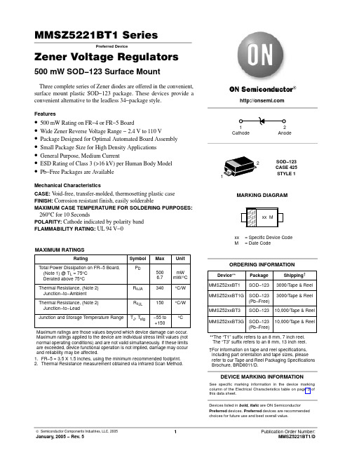
MMSZ5221BT1 SeriesPreferred DeviceZener Voltage Regulators 500 mW SOD−123 Surface MountThree complete series of Zener diodes are offered in the convenient, surface mount plastic SOD−123 package. These devices provide a convenient alternative to the leadless 34−package style.Features•500 mW Rating on FR−4 or FR−5 Board•Wide Zener Reverse V oltage Range − 2.4 V to 110 V •Package Designed for Optimal Automated Board Assembly •Small Package Size for High Density Applications •General Purpose, Medium Current•ESD Rating of Class 3 (>16 kV) per Human Body Model•Pb−Free Packages are AvailableMechanical CharacteristicsCASE:V oid-free, transfer-molded, thermosetting plastic case FINISH:Corrosion resistant finish, easily solderableMAXIMUM CASE TEMPERATURE FOR SOLDERING PURPOSES: 260°C for 10 SecondsPOLARITY:Cathode indicated by polarity band FLAMMABILITY RATING:UL 94 V−0MAXIMUM RATINGSMaximum ratings are those values beyond which device damage can occur. Maximum ratings applied to the device are individual stress limit values (not normal operating conditions) and are not valid simultaneously. If these limits are exceeded, device functional operation is not implied, damage may occur and reliability may be affected.1.FR−5 = 3.5 X 1.5 inches, using the minimum recommended footprint.2.Thermal Resistance measurement obtained via infrared Scan Method.See specific marking information in the device marking column of the Electrical Characteristics table on page 3 of this data sheet.DEVICE MARKING INFORMATIONDevices listed in bold, italic are ON Semiconductor Preferred devices. Preferred devices are recommended choices for future use and best overall value.ELECTRICAL CHARACTERISTICS (T A = 25°C unlessotherwise noted, V= 0.95 V Max. @ I = 10 mA)4.Nominal Zener voltage is measured with the device junction in thermal equilibrium at T L = 30°C $1°C.5.Z ZT and Z ZK are measured by dividing the AC voltage drop across the device by the ac current applied.The specified limits are for I Z(AC) = 0.1 I Z(dc) with the AC frequency = 1 KHz.V Z , NOMINAL ZENER VOLTAGE (V)−1012345678Figure 1. Temperature Coefficients (Temperature Range −55°C to +150°C)100101V Z , NOMINAL ZENER VOLTAGE (V)Figure 2. Temperature Coefficients (Temperature Range −55°C to +150°C)1.21.00.80.60.40.20T, TEMPERATURE (°C)Figure 3. Steady State Power Derating PW, PULSE WIDTH (ms)Figure 4. Maximum Nonrepetitive Surge Power1000100101V Z , NOMINAL ZENER VOLTAGEFigure 5. Effect of Zener Voltage onZener Impedance100101V F , FORWARD VOLTAGE (V)Figure 6. Typical Forward Voltage1000100101q V Z , T E M P E R A T U R E C O E F F I C I E N T (m V /°C )q V Z , T E M P E R A T U R E C O E F F I C I E N T (m V /°C )P p k , P E A K S U R G E P O W E R (W A T T S )Z Z T , D Y N A M I C I M P E D A N C E (W )I F , F O R W A R D C U R R E N T (m A )C , C A P A C I T A N C E (p F )V Z , NOMINAL ZENER VOLTAGE (V)Figure 7. Typical Capacitance 1000100101V Z , ZENER VOLTAGE (V)1001010.10.01V Z , ZENER VOLTAGE (V)1001010.10.01V Z , NOMINAL ZENER VOLTAGE (V)Figure 8. Typical Leakage CurrentFigure 9. Zener Voltage versus Zener Current(V Z Up to 12 V)Figure 10. Zener Voltage versus Zener Current(12 V to 91 V)I R , L E A K A G E C U R R E N T (m A )I Z , Z E N E R C U R R E N T (m A )I Z , Z E N E R C U R R E N T (m A )PACKAGE DIMENSIONSSOD−123CASE 425−04ISSUE Cǒmm inchesǓSCALE 10:1*For additional information on our Pb−Free strategy and solderingdetails, please download the ON Semiconductor Soldering and Mounting Techniques Reference Manual, SOLDERRM/D.SOLDERING FOOTPRINT*ON Semiconductor and are registered trademarks of Semiconductor Components Industries, LLC (SCILLC). SCILLC reserves the right to make changes without further notice to any products herein. SCILLC makes no warranty, representation or guarantee regarding the suitability of its products for any particular purpose, nor does SCILLC assume any liability arising out of the application or use of any product or circuit, and specifically disclaims any and all liability, including without limitation special, consequential or incidental damages.“Typical” parameters which may be provided in SCILLC data sheets and/or specifications can and do vary in different applications and actual performance may vary over time. All operating parameters, including “Typicals” must be validated for each customer application by customer’s technical experts. SCILLC does not convey any license under its patent rights nor the rights of others. SCILLC products are not designed, intended, or authorized for use as components in systems intended for surgical implant into the body, or other applications intended to support or sustain life, or for any other application in which the failure of the SCILLC product could create a situation where personal injury or death may occur. Should Buyer purchase or use SCILLC products for any such unintended or unauthorized application, Buyer shall indemnify and hold SCILLC and its officers, employees, subsidiaries, affiliates,and distributors harmless against all claims, costs, damages, and expenses, and reasonable attorney fees arising out of, directly or indirectly, any claim of personal injury or death associated with such unintended or unauthorized use, even if such claim alleges that SCILLC was negligent regarding the design or manufacture of the part. SCILLC is an Equal Opportunity/Affirmative Action Employer. This literature is subject to all applicable copyright laws and is not for resale in any manner.PUBLICATION ORDERING INFORMATION。
- 1、下载文档前请自行甄别文档内容的完整性,平台不提供额外的编辑、内容补充、找答案等附加服务。
- 2、"仅部分预览"的文档,不可在线预览部分如存在完整性等问题,可反馈申请退款(可完整预览的文档不适用该条件!)。
- 3、如文档侵犯您的权益,请联系客服反馈,我们会尽快为您处理(人工客服工作时间:9:00-18:30)。
POWER: 0.5 Wa t VOLTAGE RANGE: 2.4 - 7 5V
MMSZ2V4 - MMSZ75
Symbol
Value
Unit
Total Power Dissipation on FR-5 Board,P D
mW
(Note 1), at T L = 75 °Derated above 75 °C
6.7
mW/°C Thermal Resistance Junction to Ambient R ӨJA 340°C/W Thermal Resistance Junction to Lead R ӨJL 150
°C/W Junction Temperature Range T J -55 to + 150°C Storage Temperature Range
T STG
-55 to + 150
°C
Note :
(1) FR-5 = 3.5 x 1.5 inches
Parameter
Features
Small Package Size for High Density Applications
!!!!Total Power Dissipation 500 mW on FR-4
or FR-5 Board
Wide Zener Reverse Voltage Range 2.4 V
to 75 V
Package Designed for Optimal Automated
Board Assembly
C 500SURFACE MOUNT SILICON ZENER DIODES
: SOD-123FL
plastic body over passivated junction Method 2026: Color band denotes cathode end : Any
Case Terminals Polarity Mounting Position : Plated axial leads,
solderable per MIL-STD-750,Mechanical Data
!!!!!!Weight:0.0007 ounce, 0.02 grams
3.58 3.72 0.55 0.57 0.530.15 0.17 0.13E D 1.00 1.03 0.097 1.05 1.08 1.021 1.80 1.83 1.77 2.75 2.78 2.72A 3.653 SOD-123FL
Dim Min Max Typ B C H L All Dimensions in mm
Maximum Ratings T A = 25°C unless otherwise specified
ELECTRICAL CHARACTERISTICS (Ta = 25 °C unless otherwise note, V F
= 0.9 Vmax. @ I F
= 10 mA)
Z ZT1
(3)Z ZT2 (3)Max. Reverse @ I ZT1 = @ I ZT2 =Leakage 5 mA 1 mA Current Min
Nom Max Min Max (μA)(V)2.28 2.4 2.52100 1.7 2.160050 1.02.57 2.7 2.84100 1.9 2.460020 1.02.85 3.0 3.1595 2.1 2.760010 1.03.14 3.3 3.4795 2.3 2.9600 5.0 1.03.42 3.6 3.7890 2.7 3.3600 5.0 1.03.71 3.9 4.1090 2.9 3.5600 3.0 1.04.09 4.3 4.5290 3.3 4.0600 3.0 1.04.47 4.7 4.9480 3.7 4.7500 3.0 2.04.85 5.1 5.3660 4.2 5.3480 2.0 2.05.32 5.6 5.8840 4.8 6.0400 1.0 2.05.89 6.2 6.5110 5.6 6.6150 3.0 4.06.46 6.87.1415 6.37.280 2.0 4.07.137.57.8815 6.97.980 1.0 5.07.798.28.61157.68.7800.7 5.08.659.19.56158.49.61000.5 6.09.501010.50209.310.61500.27.010.451111.552010.211.61500.18.011.401212.602511.212.71500.18.012.351313.653012.314.01700.18.014.251515.753013.715.52000.0510.515.201616.804015.217.02000.0511.217.101818.904516.719.02250.0512.619.002021.005518.721.12250.0514.020.902223.105520.723.22500.0515.422.80
24
25.20
70
22.7
25.5
250
0.05
16.8
Notes :
(1) The type number shown have a standard tolerance of
±5% on the nominal Zener Voltage.(2) Tolerance and Voltage Designation: Zener Voltage (V Z ) is measured with the Zener Current applied for PW = 1ms.(3) Z ZT and Z ZK are measured by dividing the AC voltage drop across the device by the AC current applied. The specified limits are for I Z(AC)=0.1I Z(DC), with the AC frequency = 1 kHz.
V Z1(1, 2)
V Z2 (1, 2)
(Ω)I R @ V R @ I ZT1 = 5 mA
@ I ZT2 = 1 mA
(V)(Ω)(V)
TYPE
MMSZ2V4 MMSZ2V7 MMSZ3V0 MMSZ3V3 MMSZ3V6 MMSZ3V9 MMSZ4V3 MMSZ4V7 MMSZ5V1 MMSZ5V6 MMSZ6V2 MMSZ6V8 MMSZ7V5 MMSZ8V2 MMSZ9V1 MMSZ10 MMSZ11 MMSZ12 MMSZ13 MMSZ15 MMSZ16 MMSZ18 MMSZ20 MMSZ22 MMSZ24
ELECTRICAL CHARACTERISTICS (Ta = 25 °C unless otherwise note, V F
= 0.9 Vmax. @ I F
= 10 mA)
Z
ZT1 (3)Z ZT2 (3)Max. Reverse @ I ZT1 = @ I ZT2 =Leakage TYPE NO.
2 mA
0.5 mA Current Min
Nom Max Min Max (μ25.652728.358025.028.93000.0518.928.503031.508027.832.03000.0521.031.353334.658030.835.03250.0523.134.203637.809033.838.03500.0525.237.053940.9513036.741.03500.0527.340.854345.1515039.746.03750.0530.144.654749.3517043.750.03750.0532.948.455153.5518047.654.04000.0535.753.205658.8020051.560.04250.0539.258.006266.00200---0.24764.006872.00250---0.25270.00
75
79.00
300
--
-
0.2
57
Notes :
(1) The type number shown have a standard tolerance of ±5% on the nominal Zener Voltage.
(2) Tolerance and Voltage Designation: Zener Voltage (V Z ) is measured with the Zener Current applied for PW = 1ms.(3) Z ZT and Z ZK are measured by dividing the AC voltage drop across the device by the AC current applied. The specified limits are for I Z(AC)=0.1I Z(DC), with the AC frequency = 1 kHz.
(Ω)I R @ V R V Z1(1, 2)
V Z2 (1, 2)@ I ZT1 ZT2 = 0.1 mA
(V)(Ω)(V) MMSZ27 MMSZ30 MMSZ33 MMSZ36 MMSZ39 MMSZ43 MMSZ47 MMSZ51 MMSZ56 MMSZ62 MMSZ68 MMSZ75
= 2 mA
@ I。
