C380EX500中文资料
300C扬声器系列
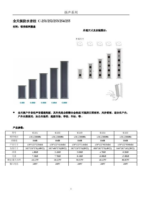
全天候防水音柱C-251/252/253/254/255材料:铝壳铝网塑盖外观尺寸及安装图示:全天候户外音柱声音通透亮丽,其外壳是由铝镁合金制成,可抵挡日照雨林、风沙雪雨,适合在户内,户外长期使用,如公共场所、超级市场、学校、车站、等...产品参数:全铝室内音柱C-263/262/261材料:铝壳铝网铝盖●全频带喇叭,声音清晰明亮●铝板制造坚固耐用●外型美观,安装方便外观尺寸及安装图示:产品参数:豪华室内音柱C-271/272/273/274/275 材料:铝壳铝网塑盖●全频带喇叭,声音清晰明亮…●铝板制造坚固耐用●外型美观,安装方便外观尺寸及安装图示:产品参数:豪华室内外音柱C-291/292/293/294/295材料:铝壳铝网塑盖室外豪华型防水音柱对人声、音乐都有还原真实的放大特性由铝合金材料制成,所以更适合户外全天侯使用。
如网球场、游泳池、花园、学校操场、市集等。
外观尺寸及安装图示:产品参数:超豪华大型音柱C-351/352/353/354/355材料:铝壳铝网铝盖超豪华大型音柱声声通透亮丽,其外壳是由铝镁合金制成,可抵挡日照雨林、风沙雪雨,适合在户内,户外长期使用。
如公共场所、超级市场、学校、车站、等。
外观尺寸及安装图示:产品参数:高质大型室外音柱C-284/283/282/281材料:铝壳铝网塑盖高质大型室外音柱声声通透亮丽,其外壳是由钢制成,低音效果好.可抵挡日照雨林、风沙雪雨,适合在户内,户外长期使用。
如公共场所、超级市场、学校、车站等。
外观尺寸及安装图示:产品参数:全天候室外大型防水音柱C-371/372/373/374/375材料:铝壳铝网塑盖外观尺寸及安装图示:产品参数:全天候室外大型防水音柱MQ-361/362/363/364/365 材料:铝壳铝网塑盖产品参数:豪华室内防水音柱C-550/560/570/580 材料:铝壳铝网塑盖产品参数:优质音柱C-391/392/331/332材料:全木质制成●全频带喇叭,声音清晰明亮●材料采用全木质制成●外型美观,安装方便产品参数:产品参数:室内音柱C-376/377/378单元类型:MQ-325:1个高音,1个喇叭单元; MQ-335: 1个高音,2个喇叭单元;MQ-345:2个高音,3个喇叭单元。
APC APC500 03-2019 v1.0 产品说明书

巖䔘♏䙫 WAN ⟇˛ 5
4. ὦ䔏䶙巖䷁⯮㜓䔉⒨凮わ䙫曢免怊㎌˛
6
5. 媲╆⊼㿶妤♏Ə✏䶙✧⇾弟⅌㜓䔉⒨䙫溿婴 IP ✗✧ 192.168.2.1˛
㨢㔀濕疋方値䕂 IP ◮◾⺃曆⍊㗪䏠⍿⋊◦Ჾỉ⨎⚝Ʋ廰Ჾ㨣奨 㓌濕妉⊁䀥 ㎋Ḛㄉ⁈Ʋ
庙Ჾ㨣媲㓌媵⊀䀥ḽ䏦ㄉ⁊˛
18
III.䜪ᶴ㙴婼
III-1. ❿㙴⩇垃 㜓Ẏ⒨昫嵇⢨㞝垡ḄƏ僤宐わ⯭⅝⭰墬ṵ⢀⢨˛
⩇垃❿㙴噸᳛ℋ濕媵 ⫄ᵥ⍿ⵓ徦䕂㤟侴俘♩䢹攢˛
4. 寞ℯ䡕宋⹝㟮䤡⥤わペ奨✏⢀杉撢垡Ḅ⬻䙫ἴ何Ə撢⬻⏵⯭⋬墬Ⅼ昫䙫
⢨嘵墬⅌Əⅴ⯭憸ⱅ垡Ḅ擨⅌⢨嘵(垡Ḅ寞ᷴ奨⭳⅏擨⅌Ə寞䕀ᷧ⯶㮜䩡 旛)˛
20
COPYRIGHT Copyright ¤ Edimax Technology Co., Ltd. all rights reserved. No part of this publication may be reproduced, transmitted, transcribed, stored in a retrieval system, or translated into any language or computer language, in any form or by any means, electronic, mechanical, magnetic, optical, chemical, manual or otherwise, without the prior written permission from Edimax Technology Co., Ltd.
17
15. 寞わ巆䜧䔢杉㋮䤡⭳ㇷ㭌檋 1-6Ə㛧⏵䂠忰“Finish”Ọ⬿㈧㛰宥⮁˛
BTA208X-500C中文资料
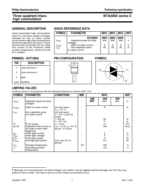
Three quadrant triacs BTA208X series Chigh commutationGENERAL DESCRIPTIONQUICK REFERENCE DATAGlass passivated high commutation SYMBOL PARAMETERMAX.MAX.MAX.UNIT triacs in a full pack,plastic envelope intended for use in motor control BTA208X-500C 600C 800C circuits where high static and dynamic V DRM Repetitive peak off-state 500600800V dV/dt and high dI/dt can occur.These voltagesdevices will commutate the full rated I T(RMS)RMS on-state current 888A rms current at the maximum rated I TSMNon-repetitive peak 656565Ajunction temperature,without the aid on-state currentof a snubber.PINNING - SOT186APIN CONFIGURATIONSYMBOLLIMITING VALUESLimiting values in accordance with the Absolute Maximum System (IEC 134).SYMBOL PARAMETERCONDITIONSMIN.MAX.UNIT -600-600-800V DRM Repetitive peak off-state -60016001800V voltagesI T(RMS)RMS on-state current full sine wave;-8AT hs ≤ 73 ˚C I TSMNon-repetitive peak full sine wave;on-state currentT j = 25 ˚C prior to surge t = 20 ms -65A t = 16.7 ms -71A I 2t I 2t for fusingt = 10 ms-21A 2s dI T /dt Repetitive rate of rise of I TM = 12 A; I G = 0.2 A;100A/µs on-state current after dI G /dt = 0.2 A/µs triggeringI GM Peak gate current -2A V GM Peak gate voltage -5V P GM Peak gate power -5W P G(AV)Average gate power over any 20 ms -0.5W periodT stg Storage temperature -40150˚C T jOperating junction -125˚Ctemperature1 Although not recommended, off-state voltages up to 800V may be applied without damage, but the triac may switch to the on-state. The rate of rise of current should not exceed 6 A/µs.ISOLATION LIMITING VALUE & CHARACTERISTICT hs = 25 ˚C unless otherwise specified SYMBOL PARAMETERCONDITIONSMIN.TYP.MAX.UNIT V isol R.M.S. isolation voltage from all f = 50-60 Hz; sinusoidal -2500V three terminals to external waveform;heatsinkR.H. ≤ 65% ; clean and dustfreeC isolCapacitance from T2 to external f = 1 MHz -10-pFheatsinkTHERMAL RESISTANCESSYMBOL PARAMETER CONDITIONSMIN.TYP.MAX.UNIT R th j-hs Thermal resistance full or half cyclejunction to heatsink with heatsink compound -- 4.5K/W without heatsink compound -- 6.5K/W R th j-aThermal resistance in free air-55-K/Wjunction to ambientSTATIC CHARACTERISTICST j = 25 ˚C unless otherwise stated SYMBOL PARAMETER CONDITIONS MIN.TYP.MAX.UNIT I GTGate trigger current 2V D = 12 V; I T = 0.1 AT2+ G+2-35mA T2+ G-2-35mA T2- G-2-35mA I LLatching currentV D = 12 V; I GT = 0.1 AT2+ G+--20mA T2+ G---30mA T2- G---20mA I H Holding current V D = 12 V; I GT = 0.1 A --15mA V T On-state voltage I T = 10 A- 1.3 1.65V V GT Gate trigger voltage V D = 12 V; I T = 0.1 A-0.7 1.5V V D = 400 V; I T = 0.1 A; T j = 125 ˚C 0.250.4-V I DOff-state leakage currentV D = V DRM(max); T j = 125 ˚C-0.10.5mADYNAMIC CHARACTERISTICST j = 25 ˚C unless otherwise stated SYMBOL PARAMETERCONDITIONSMIN.TYP.UNIT dV D /dt Critical rate of rise of V DM = 67% V DRM(max); T j = 125 ˚C; exponential 1000-V/µs off-state voltagewaveform; gate open circuitdI com /dt Critical rate of change of V DM = 400 V; T j = 125 ˚C; I T(RMS) = 8 A; without 314A/ms commutating current snubber; gate open circuitt gtGate controlled turn-on I TM = 12 A; V D = V DRM(max); I G = 0.1 A;-2µstimedI G /dt = 5 A/µs2 Device does not trigger in the T2-, G+ quadrant.MECHANICAL DATANotes1. Refer to mounting instructions for F-pack envelopes.2. Epoxy meets UL94 V0 at 1/8".DEFINITIONSData sheet statusObjective specification This data sheet contains target or goal specifications for product development. Preliminary specification This data sheet contains preliminary data; supplementary data may be published later. Product specification This data sheet contains final product specifications.Limiting valuesLimiting values are given in accordance with the Absolute Maximum Rating System (IEC 134). Stress above one or more of the limiting values may cause permanent damage to the device. These are stress ratings only and operation of the device at these or at any other conditions above those given in the Characteristics sections of this specification is not implied. Exposure to limiting values for extended periods may affect device reliability. Application informationWhere application information is given, it is advisory and does not form part of the specification.© Philips Electronics N.V. 1997All rights are reserved. Reproduction in whole or in part is prohibited without the prior written consent of the copyright owner.The information presented in this document does not form part of any quotation or contract, it is believed to be accurate and reliable and may be changed without notice. No liability will be accepted by the publisher for any consequence of its use. Publication thereof does not convey nor imply any license under patent or other industrial or intellectual property rights.LIFE SUPPORT APPLICATIONSThese products are not designed for use in life support appliances, devices or systems where malfunction of these products can be reasonably expected to result in personal injury. Philips customers using or selling these products for use in such applications do so at their own risk and agree to fully indemnify Philips for any damages resulting from such improper use or sale.。
GROUP550产品说明书

GROUP550设备说明书目录一、设备环境安装要求 (3)1、硬件规格 (4)2、网络需求 (4)二、设备安装步骤 (4)1、GROUP 550介绍-设备组成: (5)2、GROUP 550介绍-背板连线示意: (5)3、实物展示 (5)4、物理连接 (6)三、加电测试 (15)1、设备开机 (15)2、电源指示灯状态 (15)3、主屏幕显示状态 (15)四、设备系统配置 (16)1、系统开机配置 (16)2、遥控器操作方法 (21)3、呼叫对方 (22)4、高级进阶设置 (23)五、系统功能测试 (28)1、终端点对点呼叫是否能够联通 (29)2、终端多点呼叫是否能够联通 (29)3、终端输出内容画面是否为1080P (29)4、终端画面和音频是否唇音同步 (29)5、终端双流输入是否正常 (29)六、设备常见故障处理 (29)1、遥控器的充电 (29)2、设置预设位和调用 (30)3、麦克风状态指示灯 (31)4、双流的发送 (31)5、诊断: (32)6、会议常见问题 (33)7、系统维护 (35)一、设备环境安装要求1、硬件规格2、网络需求视频会议系统传输使用中国建设银行专用IP网,由于MCU是整个视频会议系统的汇聚中心,为了保证视频会议画面清晰、声音逼真,并确保中国建设银行内网与视频会议系统的安全、稳定运行,建议如下:1)为视频设备单独划分内网,使用单独Vlan。
2)MCU、录播服务器、会管服务器和设备管理服务器等设备需要连接在内网核心交换机上。
3)各个会议室视频终端到MCU之间尽量减少网络节点,避免受内网用户业务影响。
4)MCU、录播服务器、会管服务器和设备管理服务器及各个会议室视频终端均可与出资企业视频终端通信。
其间不经过防火墙、流量控制等设备。
如必需经过,需打开相关策略保证视频业务可通信。
二、设备安装步骤1、GROUP 550介绍-设备组成:名称主机镜相机全向麦克风遥控器辅材线缆实物图2、GROUP 550介绍-背板连线示意:3、实物展示4、物理连接4.1 摄像机连接4.2 双流输入4.3 音频输入4.4 音频输出音频输出接口,双声道4.5 视频输出4.6 网络接口三、加电测试1、设备开机2、电源指示灯状态蓝色橙色闪烁交替闪烁则是主机处于升级状态3、主屏幕显示状态开机后电源灯为蓝色状态待机状态电源灯为橙色色状态四、设备系统配置1、系统开机配置1.1 用遥控器选择“简体中文”1.2 选择“高级”1.3 选择“接受”1.4 选择”China”1.5 第五页系统名使用默认名称(或自行更改),然后点击”下一个”1.6 配置的设备地址,先选择手动输入IP地址,使用遥控器一次输入IP地址、网关、掩码。
WPC803说明书
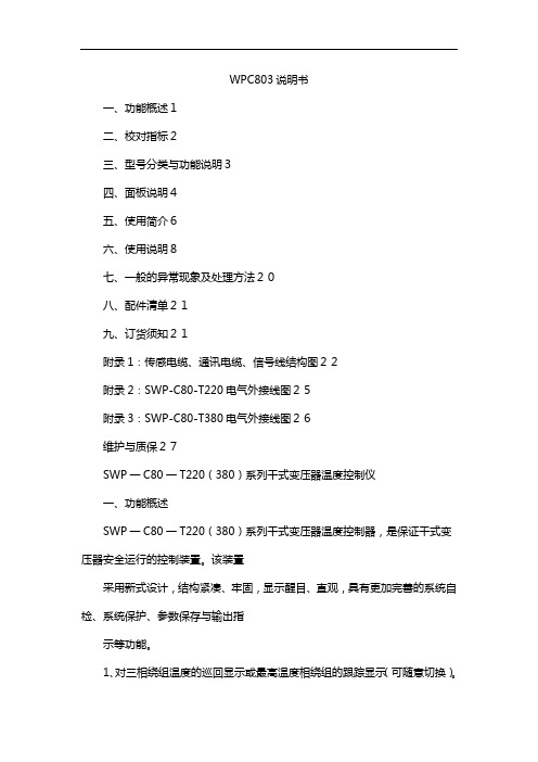
WPC803说明书一、功能概述1二、校对指标2三、型号分类与功能说明3四、面板说明4五、使用简介6六、使用说明8七、一般的异常现象及处理方法20八、配件清单21九、订货须知21附录1:传感电缆、通讯电缆、信号线结构图22附录2:SWP-C80-T220电气外接线图25附录3:SWP-C80-T380电气外接线图26维护与质保27SWP一C80一T220(380)系列干式变压器温度控制仪一、功能概述SWP一C80一T220(380)系列干式变压器温度控制器,是保证干式变压器安全运行的控制装置。
该装置采用新式设计,结构紧凑、牢固,显示醒目、直观,具有更加完善的系统自检、系统保护、参数保存与输出指示等功能。
1、对三相绕组温度的巡回显示或最高温度相绕组的跟踪显示(可随意切换)。
2、实现冷却风机启停的自动控制或手动控制(可随意切换)。
3、输出功能检测及整机测量精度检测。
4、风机启停信号显示输出及远传;超温报警信号显示输出及远传;超温跳闸信号显示输出及远传;传感器开路、风机故障、系统故障自检信号的显示、报警与输出。
5、黑匣子功能可保存停电前的全部监测参数以备查询。
6、各相绕组独立的温度示值零点与比例补偿。
7、输出三路独立4~20mA模拟电流,分别对应于A、B、C三相绕组温度(可选功能)。
8、串行通讯功能(RS-232或RS-485),并可使用“昌晖”鲁班组态软件组成SWP远程监控系统。
9、全数字式调校,摒弃了陈旧的电位器调整方式,现场使用极为方便。
1SWP一C80一T220(380)系列干式变压器温度控制仪二、校对指标温控器按JB/T7631--94《变压器用电阻温度计》标准设计。
1、测量范围:0.0~200.0°C(传感器Pt100)2、测量精度:通用型:0.5级分辨力:0.1°C3、使用条件:环境温度:-20°C~+55°C相对湿度<85%电源电压:380V(三相)220V(单相)电源频率:50±2Hz4、抗干扰性能:对共模250V(AC,50HZ)或串模200mV(AC,50HZ)干扰电压,显示值变化小于基本误差值。
EX180系列产品部件概述说明书
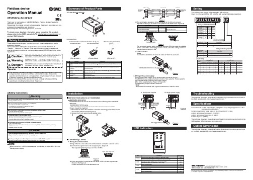
<EX180-SMJ3/-SMJ5>InstallationLED IndicationCommunication connector for CC-Link (1 pc.)(EX180-CMJ1)(EX180-CMJ2)EX180-SMJ3/5EX180-SMJ3A/5A Power supply connector(2 pcs.)(EX180-CP1)<Accessories>(2)A bus termination is required at both ends of CC-Link bus segment as shown in the Figure 2.A cable should be CC-Link-dedicated one.Figure 3Figure 42. Wiring of the power supplyConnect the power supply to the power supply connector (2 pcs.).The EX180 power supply structure consists of two systems. These systems can operate alone or with another power supply.Wire to the assigned pins. (Figure 5, Figure 6)The tightening torque is 0.22 to 0.25 Nm.•NoteGround the FG terminal with a ground resistance of 100 Ω or less.Solenoid valve power supply24 VDC The power supply for controlling the SI unit 24 VDCFigure 5A. Dual power suppliesB. Single power supplyFigure 6Turn off the power supply while setting the DIP switches.Open the cover and set the DIP switches with a small flat blade screwdriver.Connecting Cables1. Wiring for communicationWiring of the CC-Link cable and communication connector is shown below.(1)Connect the signal lines to the assigned pins. (Figure 1)The required tightening torque is 0.5 to 0.6 Nm.Figure 1Settingresistor Figure 2(3)The terminating resistance to be connected to the CC-Link networkNOTEWhen conformity to UL is necessary the SI unit must be used with a UL1310Class2 power supply.Fieldbus deviceOperation ManualEX180 Series for CC-LinkThank you for purchasing an SMC EX180 Series Fieldbus device (Hereinafter referred to as "SI unit").Please read this manual carefully before operating the product and make sure you understand its capabilities and limitations.Please keep this manual handy for future reference.To obtain more detailed information about operating this product,please refer to the SMC website (URL ) or contact SMC directly.These safety instructions are intended to prevent hazardous situations and/or equipment damage.These instructions indicate the level of potential hazard with the labels of"Caution", " Warning" or "Danger". They are all important notes for safety and must be followed in addition to International standards (ISO/IEC) and other safety regulations.OperatorTroubleshootingThe technical document states detail troubleshooting information can be found on the SMC website (URL )SpecificationsConnected load: 24VDC Solenoid valve with light and surge voltage suppressor of 1 W orless (manufactured by SMC)Current consumption of power supply for SI unit operation: 0.1 A max.Ambient temperature for operation: -10 to 50 C Ambient temperature for storage: -20 to 60 C Pollution degree 2: (UL508)The technical document states detail specification information can be found on the SMC website (URL )Outline DimensionsThe technical document states detail outline dimensions information can be found on the SMC website (URL )Akihabara UDX 15F , 4-14-1, Sotokanda, Chiyoda-ku, Tokyo 101-0021, JAP AN Phone: +81 3-5207-8249 Fax: +81 3-5298-5362URL Note: Specifications are subject to change without prior notice and any obligation on the part of the manufacturer.© 2010 SMC Corporation All Rights ReservedThe terminating resistor which is attached with each CC-Link master is available.Do not connect the terminating resistor outside, when the setting switch for the terminating resistor is ON.(4)How to connect.•NoteConnect the shield line for CC-Link cable to "SLD" of each unit.General Instructions on InstallationApplicable valve seriesThe EX180 series SI unit can be mounted on the following valve manifolds.•ManifoldsSJ2000/3000, S0700 series∗: Refer to the catalogues and operation manuals for details on the solenoid valves and manifolds.•How to mount the manifold1. Mount the SI unit to the manifold so that the mounting guide of the SI unit case mates with the manifold groove.。
ESC500说明书(1.3)
ESC500说明书ESJ-B-ESC500-560 PAGE 1 OF 1发放记录:1.2007-12-19:文件版本1.02.2009-01-17: 文件版本1.1.请参考ECN:ECN09011701. 增加接线方法和负载算法及外接电源的方案3.2009-07-27: 文件版本1.2. 请参考ECN:ECN09072001.修改反馈处理4.2009-09-28:文件版本1.3. 请参考ECN:ECN09091701.ECN09092303说明书中公司英文名称改 为ShenZhen ExSaf Electronics Co., Ltd.和软件更改探测器安装位置通过PC 软件设置。
ESC500可燃气体报警控制器 (V1.3)使 用 说 明 书深 圳 市 特 安 电 子 有 限 公 司Shenzhen ExSaf Electronics Co., Ltd.深圳市特安电子有限公司地址:电话:0755-售后服务热线:0755-******** 57网址: 深圳市南山区科技园朗山二号路五号洁净阳光园86186524 86186534传真:0755-******** 邮编:5180邮箱:sale@质量方针通过我们对工作质量的持续改进来满足顾客的需求,并使顾客得到发展及成功。
设备安装、操作和维护之前务必仔细阅读技术手册。
特别留意警告和注意事项。
所有警告都此处列出,并在手册相应章节中重复提到。
注意事项分别在相应章节中列出。
警告:专门设计安装于室内非爆炸性气体中。
它的安装必须遵照相关国家适当权威机构的公认标准。
任何操作执行之前必须确保满足当地法规和现场要求。
控制器和现场设备内部的任何操作都必须由专业人员执行。
进入到设备内部之前,先切断或隔离电源。
切勿试图在可燃气体/毒气出现时开启探测器或更换/安装传感器。
电缆线路必须遵照其所在国家权威机构的公认标准并满足系统电气要求。
打开探测器机壳之前,为减少危险气体点燃的风险,应先断开电源。
常用三极管参数大全

玉林万顺达电脑芯片级维修资料 2010-07-20整理玉林万顺达电脑芯片级维修资料 2010-07-20整理玉林万顺达电脑芯片级维修资料 2010-07-20整理玉林万顺达电脑芯片级维修资料 2010-07-20整理玉林万顺达电脑芯片级维修资料 2010-07-20整理玉林万顺达电脑芯片级维修资料 2010-07-20整理玉林万顺达电脑芯片级维修资料 2010-07-20整理玉林万顺达电脑芯片级维修资料 2010-07-20整理玉林万顺达电脑芯片级维修资料 2010-07-20整理玉林万顺达电脑芯片级维修资料 2010-07-20整理玉林万顺达电脑芯片级维修资料 2010-07-20整理玉林万顺达电脑芯片级维修资料 2010-07-20整理玉林万顺达电脑芯片级维修资料 2010-07-20整理玉林万顺达电脑芯片级维修资料 2010-07-20整理玉林万顺达电脑芯片级维修资料 2010-07-20整理玉林万顺达电脑芯片级维修资料 2010-07-20整理玉林万顺达电脑芯片级维修资料 2010-07-20整理玉林万顺达电脑芯片级维修资料 2010-07-20整理玉林万顺达电脑芯片级维修资料 2010-07-20整理玉林万顺达电脑芯片级维修资料 2010-07-20整理玉林万顺达电脑芯片级维修资料 2010-07-20整理玉林万顺达电脑芯片级维修资料 2010-07-20整理玉林万顺达电脑芯片级维修资料 2010-07-20整理玉林万顺达电脑芯片级维修资料 2010-07-20整理玉林万顺达电脑芯片级维修资料 2010-07-20整理玉林万顺达电脑芯片级维修资料 2010-07-20整理玉林万顺达电脑芯片级维修资料 2010-07-20整理玉林万顺达电脑芯片级维修资料 2010-07-20整理玉林万顺达电脑芯片级维修资料 2010-07-20整理玉林万顺达电脑芯片级维修资料 2010-07-20整理。
电缆型号与名称大全
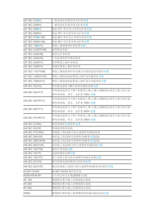
BPTGGPP2 BPTVVPP2 BPTYJVPP2 BSBE BSBEB BTTQ BTTVQ BTTVZ BTTZ BV BV-GE BVJ-105 BVJ-90 BVJVJ-90 BVJVJB-90 BVN BVN-90 BVNVB BVR BVV BVVB BVZA-GE BVZ-GE BVZNH-GE BVZW-GE BX BXF BXR BXVW BXY BYJ BYJF BYV CCA CEF/DA CEF80/DA
乙丙绝缘氯丁内套裸钢丝编织铠装船用电力电缆,DA 型 乙丙绝缘氯丁内套钢丝编织铠装聚氯乙烯外套船用电力电缆,DA 型 乙丙绝缘氯丁护套船用电力软电缆,DA 型 乙丙绝缘氯磺化聚乙烯护套船用电力电缆,DA 型
CEh80/DA CEH82/DA
CEH90/DA
CEH92/DA CEHR/DA CEV/DA CEV80/DA CEV82/DA CEV90/DA CEV92/DA CGLHD CGLHJ CGLN CGLW CHE82
铜芯聚氯乙烯绝缘低烟无卤阻燃型无接点分支导线
铜芯橡皮绝缘棉纱或其它相当纤维编织电线 铜芯橡皮绝缘氯丁或其他相当的合成胶混合物护套电线 铜芯橡皮绝缘棉纱或其它相当纤维编织软电线 铜芯橡皮绝缘聚氯乙烯护套电缆(线) 铜芯橡皮绝缘黑色聚乙烯护套电线 铜芯交联聚乙烯绝缘电线 铜芯辐照交联聚乙烯绝缘电线 额定电压 300/500 铜芯聚乙烯绝缘聚氯乙烯护套电缆 铜包铝线 乙丙绝缘氯丁护套船用电力电缆,DA 型 乙丙绝缘氯丁内套裸铜丝编织铠装船用电力电缆,DA 型 乙丙绝缘氯丁内套铜丝编织铠装聚氯乙烯外套船用电力电缆,DA 型
聚氯乙烯绝缘Байду номын сангаас护套电梯及可挠性连接用扁形电缆
聚氯乙烯绝缘耐油聚氯乙烯护套屏蔽型软电缆
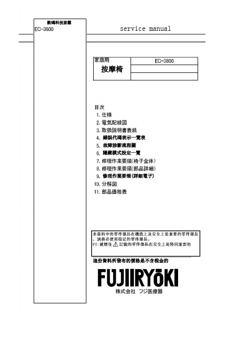
富士按摩椅EC-3800 维修手册 按摩器材
X 左右各1
・背墊
X
1
・螺栓帽 Fl X
2 ・使用說明書 X
1
・螺栓帽 F1 X
2 ・原文資料不足 X
1
・螺栓帽 R1 X
4 ・HAPI傳單
X
1
・原文資料不足 ・問卷調查明信片 X
1
・操作器架
X
1
・地墊
X
1
・六腳板手
X
1
本體尺寸
本體重量 包裝尺寸 包裝重量 堆疊數 包裝規格
更換腳台 感應器組裝件。
更換腳台 感應器組裝件。
更換遙控器。 更換控制板。
檢查控制與產品型號。
檢查控制與產品型號。
故障診斷流程圖
1. 當電源無法進入(連螢幕無顯示)
檢查電源插頭及插座是否連接妥當? NO
請將插頭插好
Yes
電源開關是否已開啟ON的狀態
NO 把電源開闢打開至ON的狀態
Yes
按下開關鍵馬達還是無動作時
子回路檢查設備或良品確認)
Yes 搖控器的伸或縮的鍵, 主控制板的連接器 No
CN23 是否有DC140V輸出(用電子回路檢查 設備或良品確認)
Yes
應器 電路板是否故障, 或是感應器信號 用4-芯 線是否斷線
No
Yes
更換腳部按摩器滑動驅動組
腳台 角度上升至30度以上, 再 次確認 轉接連接器 確時接好 轉接連接器 確時接好 更換主控制板端的線 更換主控制板
數碼科技放鬆
service manual
按摩椅
錯誤代碼表示一覽表 故障診斷流程圖 隱藏模式設定一覽
修理作業要領(詳細電子)
這份資料所發布的價格是不含稅金的
馬達形式
ELENESSA电梯备件资料(盖章版)
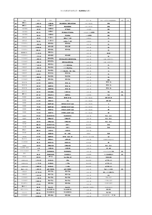
恒大电梯备件标准定价(ELENESSA电梯)
品目 231 231 231 231 231 231 231 231 231 231 231 231 231 231 231 231 231 235 235 235 235 235 235 235 235 235 235 235 235 235 235 235 235 235 235 235 235 235 235 235 235 235 235 235 235 235 235 235 235 235 235 235 235 235 235 235 235 235 235
恒大电梯备件标准定价(ELENESSA电梯)
品目 203 203 203 203 203 203 203 203 203 203 203 203 203 203 203 203 203 203 203 203 203 203 203 203 203 203 203 203 203 203 203 203 203 203 203 203 203 203 203 203 203 203 203 203 206 207 207 207 207 213 214 214 214 214 214 221 226 226 231
规格型号 DOR-261A DOR-275Cቤተ መጻሕፍቲ ባይዱDOR-560 DOR-221A X44BX-37 ZWS30-12/J LDA50F-12 X59LX-222 DOR-1241 DOR-1231 DOR-565 DOR-590A DOR-710B JW-MW11RKK 单极单投 黑色 JW-MW21RKK-027L 2极单投 黑色 ZJL6V-005 YX201B497-02 KCZ-900A ZYBAN-001 ZYBAN-001 LHS-451A LHS-452A LHD-730A LHD-730A LHD-730A LHS-420A LHB-056A LHB-056A LHB-056A LHB-056A LHB-058A LHB-058A LHB-055A LHB-055A LHB-051A LHB-051A ZDH01-016 ZDH01-028 FL1D-2M FL2D-2M WD2301 LP1S-26G-R LP1S-26G-M LP1S-26G-W MAK YE603C090-01 YE603C565-01 YE602B303-01 YE602B176-01 YE602B099-01 YE603C009-01 YE603C208-01 YE603C566-01 YE602B304-01 YE602B176-19 YE602C969-03 YE603C090-01 YE603C565-01 YE602B303-03
SD300C08C资料
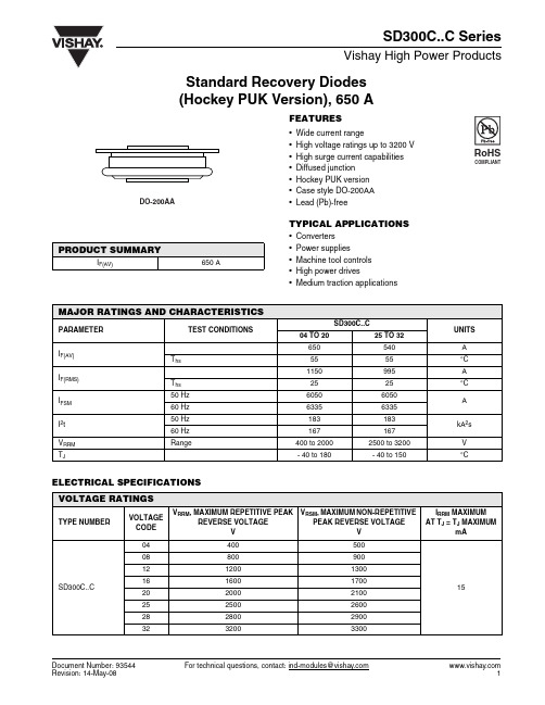
Document Number: 93544For technical questions, contact: ind-modules@Standard Recovery Diodes(Hockey PUK Version), 650 ASD300C..C SeriesVishay High Power ProductsFEATURES•Wide current range•High voltage ratings up to 3200 V •High surge current capabilities •Diffused junction •Hockey PUK version •Case style DO-200AA •Lead (Pb)-freeTYPICAL APPLICATIONS•Converters •Power supplies•Machine tool controls •High power drives•Medium traction applicationsELECTRICAL SPECIFICATIONS PRODUCT SUMMARYI F(AV)650 AMAJOR RATINGS AND CHARACTERISTICSPARAMETER TEST CONDITIONS SD300C..CUNITS 04 TO 2025 TO 32I F(AV)650540A T hs 5555°C I F(RMS)1150995A T hs 2525°C I FSM 50 Hz 60506050A 60 Hz 63356335I 2t 50 Hz 183183kA 2s 60 Hz 167167V RRM Range400 to 20002500 to 3200V T J- 40 to 180- 40 to 150°CVOLTAGE RATINGSTYPE NUMBERVOLTAGECODEV RRM , MAXIMUM REPETITIVE PEAK REVERSE VOLTAGE V V RSM , MAXIMUM NON-REPETITIVEPEAK REVERSE VOLTAGEVI RRM MAXIMUM AT T J = T J MAXIMUMmASD300C..C044005001508800900121200130016160017002020002100252500260028280029003232003300元器件交易网 For technical questions, contact: ind-modules@Document Number: 93544SD300C..C SeriesVishay High Power Products Standard Recovery Diodes(Hockey PUK Version), 650 ANote•The table above shows the increment of thermal resistance R thJ-hs when devices operate at different conduction angles than DCFORWARD CONDUCTIONPARAMETERSYMBOL TEST CONDITIONSSD300C..C UNITS 04 TO 2025 TO 32Maximum average forward current at heatsink temperature I F(AV)180° conduction, half sine wave Double side (single side) cooled650 (380)540 (250)A 55 (85)55 (85)°CMaximum RMS forward currentI F(RMS)25 °C heatsink temperature double side cooled 1150995AMaximum peak, one-cycle forward, non-repetitive surge currentI FSMt = 10 ms No voltage reapplied Sinusoidal half wave,initial T J = T J maximum6050t = 8.3 ms 6335t = 10 ms 100 % V RRM reapplied 5090t = 8.3 ms 5330Maximum I 2t for fusing I 2t t = 10 ms No voltage reapplied 183kA 2st = 8.3 ms 167t = 10 ms 100 % V RRM reapplied129t = 8.3 ms118Maximum I 2√t for fusingI 2√t t = 0.1 to 10 ms, no voltage reapplied1830 kA 2√s Low level value of threshold voltage V F(TO)1(16.7 % x π x I F(AV) < I < π x I F(AV)), T J = T J maximum 0.95VHigh level value of threshold voltage V F(TO)2(I > π x I F(AV)), T J = T J maximum1.00Low level values of forward slope resistancer f1(16.7 % x π x I F(AV) < I < π x I F(AV)), T J = T J maximum 0.75m ΩHigh level values of forward slope resistancer f2(I > π x I F(AV)), T J = T J maximum 0.72Maximum forward voltage dropV FMI pk = 1500 A, T J = T J maximum; t p = 10 ms sinusoidal wave2.08VTHERMAL AND MECHANICAL SPECIFICATIONSPARAMETER SYMBOL TEST CONDITIONSSD300C..CUNITS04 TO 2025 TO 32Maximum operating temperature range T J - 40 to 180- 40 to 150°CMaximum storage temperature range T Stg - 55 to 200Maximum thermal resistance,junction to heatsink R thJ-hsDC operation single side cooled 0.163K/W DC operation double side cooled0.073Mounting force, ± 10 %4900 (500)N (kg)Approximate weight 70gCase styleSee dimensions - link at the end of datasheetDO-200AAΔR thJ-hs CONDUCTIONCONDUCTION ANGLESINUSOIDAL CONDUCTION RECTANGULAR CONDUCTION TEST CONDITIONSUNITSSINGLE SIDEDOUBLE SIDESINGLE SIDEDOUBLE SIDE180°0.0170.0170.0110.012T J = T J maximumK/W120°0.0200.0200.0200.02090°0.0250.0250.0270.02760°0.0360.0360.0380.03830°0.0640.0620.0650.062元器件交易网SD300C..C Series Standard Recovery Diodes(Hockey PUK Version), 650 AVishay High Power ProductsFig. 1 - Current Ratings Characteristics Fig. 2 - Current Ratings Characteristics Fig. 3 - Current Ratings Characteristics Fig. 4 - Current Ratings Characteristics Fig. 5 - Current Ratings Characteristics Fig. 6 - Current Ratings Characteristics元器件交易网Document Number: 93544For technical questions, contact: ind-modules@ SD300C..C SeriesVishay High Power Products Standard Recovery Diodes(Hockey PUK Version), 650 AFig. 7 - Current Ratings Characteristics Fig. 8 - Current Ratings Characteristics Fig. 9 - Forward Power Loss CharacteristicsFig. 10 - Forward Power Loss Characteristics Fig. 11 - Maximum Non-Repetitive Surge Current Single and Double Side CooledFig. 12 - Maximum Non-Repetitive Surge Current Single and Double Side Cooled元器件交易网 For technical questions, contact: ind-modules@ Document Number: 93544Document Number: 93544For technical questions, contact: ind-modules@SD300C..C SeriesStandard Recovery Diodes (Hockey PUK Version), 650 AVishay High Power ProductsFig. 13 - Forward Voltage Drop CharacteristicsFig. 14 - Thermal Impedance Z thJC CharacteristicsORDERING INFORMATION TABLELINKS TO RELATED DOCUMENTSDimensions/doc?95248元器件交易网Disclaimer Legal Disclaimer NoticeVishayAll product specifications and data are subject to change without notice.Vishay Intertechnology, Inc., its affiliates, agents, and employees, and all persons acting on its or their behalf (collectively, “Vishay”), disclaim any and all liability for any errors, inaccuracies or incompleteness contained herein or in any other disclosure relating to any product.Vishay disclaims any and all liability arising out of the use or application of any product described herein or of any information provided herein to the maximum extent permitted by law. The product specifications do not expand or otherwise modify Vishay’s terms and conditions of purchase, including but not limited to the warranty expressed therein, which apply to these products.No license, express or implied, by estoppel or otherwise, to any intellectual property rights is granted by this document or by any conduct of Vishay.The products shown herein are not designed for use in medical, life-saving, or life-sustaining applications unless otherwise expressly indicated. Customers using or selling Vishay products not expressly indicated for use in such applications do so entirely at their own risk and agree to fully indemnify Vishay for any damages arising or resulting from such use or sale. Please contact authorized Vishay personnel to obtain written terms and conditions regarding products designed for such applications.Product names and markings noted herein may be trademarks of their respective owners.元器件交易网Document Number: 。
EX500说明书
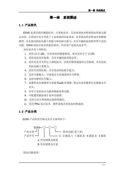
出厂时已将基准温度补偿器Cu50接至9A、9B。
4.触发记录控制输入
将触发记录控制开关(无源)的两端接至K1、K2。如果不需要触发记录功能,K1、K2端可空置。
5.报警继电器输出
H1-C1-L1~H8-C8-L8为8组报警继电器输出端子,C为两组继电器输出的共用端。H(1~8)-C(1~8)为上限报警输出,L(1~8)-C(1~8)为下限报警输出。
·实时测量数据对应的棒柱高度,棒图顶部显示观察范围上限,底部显示观察范围下限。
·实时测量数据位于棒图下方。
图3.2 棒图显示方式画面
3.棒图画面种类:若仪表的通道数设定为8,则最多有6种棒图画面,即单通道、双通道、3通道、4通道、6通道、8通道。
3.1.3曲线显示方式
1.用途:
·以曲线方式显示从当前时间开始的一个时段的测量数据,更新周期为观察比例×记录间隔(秒)。
第二章 上电与接线
2.1上电
1.打开包装箱,检查仪表外观是否有损伤,并按装箱单检验附件是否齐全。若有问题,请与我公司销售人员联系。
2.将电源线接到仪器电源接线端子上,并将电源插头插到220VAC插座上。
3.打开仪器前面版上的电源开关,仪器自动进入自检状态。若自检通过,屏幕上将出现某种视图画面,这表明仪表工作正常。若仪表重复进行自检而无法进入视图画面,表明仪表系统存在故障请与我公司销售人员联系。
·实时测量数据。通常显示测量数据,若测量数据超出量程上限,则显示“++++++”,若测量数据超出量程下限,则显示“------”,发生断偶则显示“██████”。对于设定为流量累计的流量通道,该位置可以显示流量瞬时值,或者显示流量累计值,可实现显示内容切换控制,见3.4.2之9。
extech 380950 80a 交流 直流微型钳式测量仪 用户手册说明书

用户手册型号38095080A交流/直流微型钳式测量仪简介感谢您购买Extech 80A交流/直流微型钳式测量仪。
这款型号为380950的仪表可测量交流/直流电流、交流/直流电压、电阻、频率、电容、工作周期、二极管测试和连通性。
这款钳式测量仪在装运前经过了充分测试和校准,如精心使用,可保证多年的可靠服务。
安全国际安全符号该符号出现在其他符号或端子旁,表示用户必须参考手册,了解相关信息。
该符号出现在端子旁,表示在正常使用情况下可能存在危险电压。
双层绝缘安全说明∙不要超过任何功能的最高允许的输入范围。
∙在选择了电阻功能时,仪表上不能施加电压。
∙当仪表不使用时,应把功能开关设置到OFF位置。
∙如果仪表不使用超过60天,那么应取出电池。
警告∙在测量之前应把功能开关设置到合适位置。
∙在测量电压时,不能切换到电流/电阻模式。
∙不要测量电压超过240V的电路电流。
∙在改变量程时,把测试导线从待测试的电路上断开。
警告∙本仪表如错误使用可能会造成伤害,触电或人身伤亡。
在操作本仪表之前应阅读并理解本用户手册。
∙在更换电池之前应拆下测试导线。
∙在操作本仪表之前应检查测试导线的状态和仪表本身是否破损。
在使用之前应进行修理或更换。
∙如果电压高于25VAC rms或35VDC,在进行测量时应非常谨慎。
该等级的电压有触电风险。
∙在进行二极管、电阻或连通性测试之前,应给电容放电,断开待测试设备的电源。
∙因为电气接头与凹陷的电触头的连接不确定,检查电气插座的电压很困难,有时候可能会发生错误。
应采用其他方式保证端子不带电。
∙如果未按照制造商规定的方式使用设备,可能会破坏设备所提供的保护措施。
仪表图示1. 电流感应钳2. 钳开口开关3. 功能选择开关4. 液晶显示屏5. 调零按钮6. 数据保持和背光按钮7. 模式选择按钮8. 量程选择按钮9. Hz/%/工作周期按钮10. COM输入插口11. V/ Hz插口12. 电池盖(背面)AC 交流DC 直流负号AUTO 自动设定量程模式ZERO 调零模式•)))连通性声音提醒数据保持模式电量低图标二极管测试模式m 毫V伏特A安培K千M兆Ω欧姆操作注意:在使用本仪表之前应阅读并了解在本操作手册的安全部分所列出的所有警告信息。
Protronic 100、Protronic 500 550 和 Digitric 500 控制器
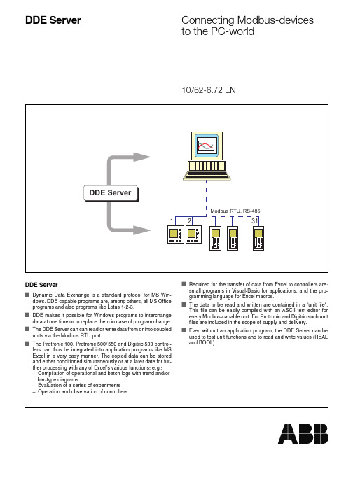
DDE Servers Dynamic Data Exchange is a standard protocol for MS Win-dows. DDE-capable programs are, among others, all MS Office programs and also programs like Lotus 1-2-3.s DDE makes it possible for Windows programs to interchange data at one time or to replace them in case of program change. s The DDE Server can can read or write data from or into coupled units via the Modbus RTU port.s The Protronic100, Protronic500/550 and Digitric500 control-lers can thus be integrated into application programs like MS Excel in a very easy manner. The copied data can be stored and either conditioned simultaneously or at a later date for fur-ther processing with any of Excel’s various functions: e.g.:–Compilation of operational and batch logs with trend and/or bar-type diagrams–Evaluation of a series of experiments–Operation and observation of controllers s Required for the transfer of data from Excel to controllers are: small programs in Visual-Basic for applications, and the pro-gramming language for Excel macros.s The data to be read and written are contained in a “unit file“.This file can be easily compiled with an ASCII text editor for every Modbus-capable unit. For Protronic and Digitric such unit files are included in the scope of supply and delivery.s Even without an application program, the DDE Server can be used to test unit functions and to read and write values (REAL and BOOL).DDE Server Connecting Modbus-devicesto the PC-world10/62-6.72 ENDDE ServerConnecting Modbus-devices to the PC-world10/62-6.72 ENABB Automation Products GmbH Hoeseler Platz 2D-42579 HeiligenhausPhone+49(0)20 56 - 12 51 81Fax +49(0)20 56 - 12 50 81 Subject to technical changes. Printed in the Fed. Rep. of Germany10/62-6.72 EN02.02Hardware requirementsPCEquipped with at least 486 CPU and a minimum 8 MByte RAM.Recommended is a Pentium CPU with higher clock frequency to enable quick displaysSoftware requirementsIncluded in the scope of supply and delivery are two program versions:16-Bit version for Windows 3.1 and 3.1132-Bit version for Windows 95 and NTForm and scope of delivery3.5“ compressed diskette, self-unpacking,containing program, on-line help and unit files forProtronic and Digitric, short installation manualProgram languageGerman, english LicencesSingle licenceThe programs are subject to the usual copyright regulations on software. The may only be installed on a PC. It is not permitted to use the programs on PC networks. If you sell the single licence to a third party, please pass on the original diskette to the purchaser and delete the program on your installation.Multiple licenceA multiple licence permits the programs to be installed at several locations within the company and allows the programs to be used on PC networks.Resale licencePossessors of a resale licence are allowed to sell the DDE Sever to third parties, together with their own applications. They must however oblige the customer not to use the DDE Server alone but only within the context of a general application. It is also not allo-wed to sell it to other third parties.Technical data。
QBZ3-80、660(380)SF
二、用途和适用范围 本起动器适用于煤矿井下,在交流50Hz电压 380V或660V供电线路中,对掘进工作面的通风、 排水、抽气进行不间断控制,具备了双机双电源 起动器自动转换的全部控制功能。 1、防爆类型:矿用隔爆型;防爆标志:ExdI。 2、执行标准:MT111-1998、Q/ZJZ111-2009。 3、起动器型号含义
b、主通风机起动后,合上隔离开关2SGK、2B得电,当支路对地 绝缘值符合要求时,ADB2的23#、24#触点闭合。 2KZ得电吸合→2K2-1闭合自保→2KZ2-2闭合给整流桥送电,为备 用通风机的起动做好准备。 当主通风机或主起动器出现故障时:1KZ失电→KM1失电→KM1-6 闭合→SJ2吸合→SJ2-1延时闭合→真空接触器KM2吸合→备用通风 机自动起动。 同理,当备用通风机或备用起动器出现故障时:2KZ失电→2KM 失电→2KM-6闭合→1SJ吸合→1SJ-1延时吸合→真空接触器1KM吸 合→主通风机自动起动,从而实现了主通风机和备用通风机相互自动 倒台的目的。 c、若两路供电系统出现故障,不能正常供电时,不需将隔离开关 1SGK、2SGK分断,当两路供电系统恢复供电时,在符合《煤矿安全 规程》有关要求的情况下,必需按下起动按钮1QA或2QA重新起动, 原理重复a、b步骤。 d、时间继电器1SJ、2SJ是为了避免带负荷起动而设置的,时间 可调范围为0-50s,4个档位,可根据用户的要求选取时间段。 e、两接线室内分别设有111#、113#和211#、213#接线端子,无 论接哪两个端子,主通风机或备用风机开启时,都能实现风电闭锁的 目的。
图一:QBZ3-80/660(380)S起动器电气原理图
七、使用与维护 1、使用 ①打开转盖,根据被控制的局部通风机的功率大小,对保护器电 流进行选择; ②用1000V兆欧表检查绝缘电阻值(注意断开L、L线); ③作耐压试验时,阻容吸收装置、ADB的L、L线须与主回路断 开; ④接通电源,起动器起动数次,接触器分合声应清脆,若电压降 到85%额定电压时,接触器闭合应没有明显两次声; ⑤对过载、短路、断相、漏电闭锁保护进行试验时,首先断开起 动器的隔离开关,将手柄置于“分”位置,闭锁螺栓,将手柄锁牢, 使之不能再闭合,然后打开转盖。 进行每项保护实验(过载、短路、断相、漏电闭锁)时,应按以 下程序逐项进行,将各档位开关分别置于试验位置,各功能正常后, 合上转盖,重新将隔离开关闭合,主回路送电。 对不同供电电压:(380V或660V)的漏电闭锁值,只要改变L 或L线的不同接线位置,即可获得不同的动作值。
