SFH303F-3中文资料
SFH2430中文资料
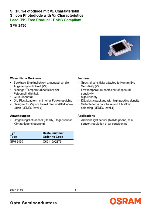
Silizium-Fotodiode mit V λ Charakteristik Silicon Photodiode with V λ CharacteristicsLead (Pb) Free Product - RoHS Compliant 2007-04-031SFH 2430Wesentliche Merkmale•Spektrale Empfindlichkeit angepasst an die Augenempfindlichkeit (V λ)•Niedriger Temperaturkoeffizient der Fotoempfindlichkeit •Gute Linearität•DIL-Plastikbauform mit hoher Packungsdichte •Geeignet für Vapor-Phase Löten und IR-Reflow Löten (JEDEC level 4) Anwendungen•Umgebungslichtsensor (Handy, Regensensor, Klimaanlagensteuerung)Typ Type Bestellnummer Ordering Code SFH 2430Q65110A2673Features•Spectral sensitivity adapted to Human Eye Sensitivity (V λ)•Low temperature coefficient of spectral sensitivity •high linearity•DIL plastic package with high packing density •Suitable for vapor-phase and IR-reflow soldering (JEDEC level 4) Applications•Ambient light sensor (Mobile phone, rain sensor, regulation of air conditioning)2007-04-032GrenzwerteMaximum Ratings Bezeichnung ParameterSymbol SymbolWert Value Einheit Unit Betriebs- und LagertemperaturOperating and storage temperature range T op ; T stg – 40 … + 100°C Sperrspannung Reverse voltageV R 6V Verlustleistung, T A = 25 °C Total power dissipationP tot150mWKennwerte (T A = 25 °C, Normlicht A, T = 2856 K)Characteristics (T A = 25 °C, standard light A, T = 2856 K) Bezeichnung ParameterSymbol SymbolWert Value Einheit Unit Fotoempfindlichkeit, V R = 5 V Spectral sensitivityS5.8 (>4)nA/Ix Wellenlänge der max. Fotoempfindlichkeit Wavelength of max. sensitivityλS max 570nm Spektraler Bereich der Fotoempfindlichkeit S = 10% von S maxSpectral range of sensitivity S = 10% of S maxλ400 (900)nmBestrahlungsempfindliche Fläche Radiant sensitive areaA 7.00mm 2Abmessung der bestrahlungsempfindlichen FlächeDimensions of radiant sensitive area L × BL × W2.65 × 2.65mm × mmHalbwinkel Half angleϕ± 60Grad deg.Dunkelstrom, V R = 5V Dark currentI R 0.1 (<5)nA Spektrale Fotoempfindlichkeit, λ = 550 nm Spectral sensitivityS λ0.17A/W Anstiegs- und Abfallzeit des Fotostromes Rise and fall time of the photocurrent R L = 50 k Ω; V R = 5 V; λ = 550 nm t r , t f200μsDurchlaßspannung, I F = 100 mA, E = 0 Forward voltageV F1.2VKapazität, V R= 0 V, f = 1 MHz, E = 0 Capacitance C1000pFTemperaturkoeffizient von I SC Temperature coefficient of I SC TCI0.16%/KKennwerte (T A = 25 °C, Normlicht A, T = 2856 K) Characteristics (T A = 25 °C, standard light A, T = 2856 K) (cont’d)Bezeichnung Parameter SymbolSymbolWertValueEinheitUnit2007-04-0332007-04-034Relative Spectral Sensitivity S= f (λ)Dark Current I= f (V ), E = 0Directional Characteristics SPhotocurrent I P /I P(25 °C) = f (T A ) E = 1000 lx, V = 5 VCapacitanceC = f (V ), f = 1 MHz, E = 0Total Power Dissipation2007-04-035Maßzeichnung Package OutlinesMaße in mm (inch) / Dimensions in mm (inch).Maße in mm / Dimensions in mm solder padLötbedingungen Vorbehandlung nach JEDEC Level 4 Soldering Conditions Preconditioning acc. to JEDEC Level 4 Reflow Lötprofil für bleifreies Löten(nach J-STD-020C)Published byOSRAM Opto Semiconductors GmbHWernerwerkstrasse 2, D-93049 Regensburg© All Rights Reserved.The information describes the type of component and shall not be considered as assured characteristics.Terms of delivery and rights to change design reserved. Due to technical requirements components may contain dangerous substances. For information on the types in question please contact our Sales Organization.PackingPlease use the recycling operators known to you. We can also help you – get in touch with your nearest sales office. By agreement we will take packing material back, if it is sorted. You must bear the costs of transport. For packing material that is returned to us unsorted or which we are not obliged to accept, we shall have to invoice you for any costs incurred.Components used in life-support devices or systems must be expressly authorized for such purpose! Critical components 1 , may only be used in life-support devices or systems 2 with the express written approval of OSRAM OS.1 A critical component is a component usedin a life-support device or system whose failure can reasonably be expected to cause the failure of that life-support device or system, or to affect its safety or effectiveness of that device or system.2 Life support devices or systems are intended (a) to be implanted in the human body, or (b) to support and/or maintain and sustain human life. If they fail, it is reasonable to assume that the health of the user may be endangered.2007-04-036。
SFH203中文资料

TCV
–2.6
–2.6
mV/K
TCI
%/K
0.18
–
–
0.2
NEP
2.9 x 10⁻¹⁴ 2.9 x 10⁻¹⁴
W
√Hz
D*
3.5 x 10¹² 3.5 x 1012 cm · √Hz
W
Semiconductor Group
Photocurrent IP = f (Ee), VR = 5 V Open-circuit-voltage VL= f (Ee) SFH 2030 F
Total power dissipation Ptot = f (TA)
Dark current IR characteristics Srel = f (ϕ)
Spektraler Bereich der Fotoempfindlichkeit S = 10% von Smax Spectral range of sensitivity S = 10% of Smax Bestrahlungsempfindliche Fläche Radiant sensitive area
VF
Forward voltage
420 (≥ 350) –
mV
–
370 (≥ 300) mV
80
–
µA
–
25
µA
5
5
ns
1.3
1.3
V
Kapazität, VR = 0 V, f = 1 MHz, E = 0
C0
11
11
pF
Capacitance
FM303中文资料
元器件交易网
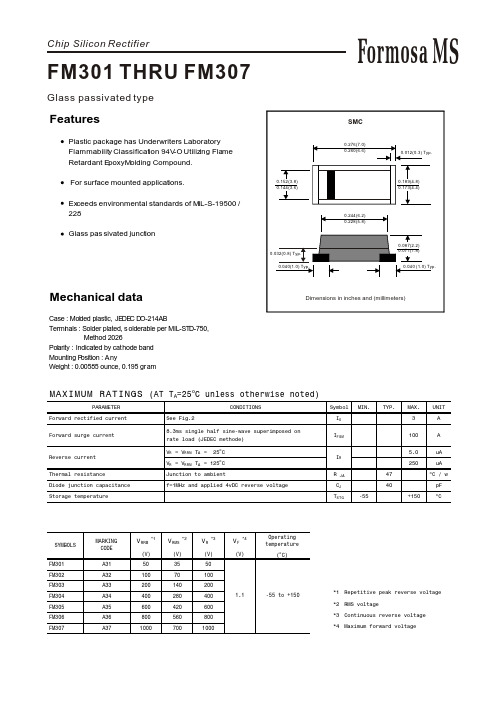
RATING AND CHARACTERISTIC CURVES (FM301 THRU FM307)
FIG.1-TYPICAL FORWARD CHARACTERISTICS
AVERAGE FORWARD CURRENT,(A) 3.0 2.5 2.0 1.5 1.0 0.5 0 0
Tj=25 C
.01 0
.01
.05
.1
.5
1
5
10
50
100
20
40
60
80
100 120 140
REVERSE VOLTAGE,(V)
PERCENT OF RATED PEAK REVERSE VOLTAGE,(%)
元器件交易网
Chip Silicon Rectifier
FM301 THRU FM307
Glass passivated type
Formosa MS
SMC
0.276(7.0) 0.260(6.6) 0.012(0.3) Typ.
Features
Plastic package has Underwriters Laboratory Flammability Classification 94V-O Utilizing Flame Retardant Epoxy Molding Compound. For surface mounted applications. Exceeds environmental standards of MIL-S-19500 / 228 Glass pas sivated junction
(V) 35 70 140 280 420 560 700
欧瑞传动注塑机伺服系统说明书

本产品的安全运行取决于正确的安装和操作以及运输与保养维护,请务必遵守本手册中使用的如下安全标识: 错误的操作将引发危险情况,导致人身伤亡。
错误的操作将引发危险情况,导致轻度或中度人身伤害,损坏设备。 另外,该标识中所述事项有时也可能造成严重的后果。 驱动器及电机上标识符的意义如下: 电压高,有电击危险。
4 电气连接........................................................................................................................................ 20
2
4.1 电液系统构成.................................................................................................................... 20 4.2 电气连接 ........................................................................................................................... 21 4.2.1 主电路接线示意............................................................................................................ 22 4.2.2 控制端子功能简介和接线示意图 ................................................................................ 23 4.2.3 拨码开关介绍................................................................................................................ 24
VF03中文手册
益系数(amplification factor)应为0或1(取决于探针类型),对于介 电常数<10时,增益系数(amplification factor)应为2或3
正常情况下不需设置门阀值(threshold),但对于一些应用中, 比如管嘴的反射,则需要设置较高的门阀值(threshold)。 注: 在设置门阀值(threshold)时,不推荐在空罐或满罐时设置。
要求 B>A. 3.3 避免钢缆与管壁接触
3.4 雷达之间的间隔距离,最小距离为 2m.
单杆/单缆距壁最小距离为 300mm 同轴离墙壁无限制 双杆/双缆距壁最小距离为 100mm 3.2 管嘴安装方式
3.5 罐内带搅拌的需固定底部,且勿安装于下料口位置,避免下料对 测量的影响。 4.0 电气连接
避免管嘴高度 A 大于 150mm(5.9”),尤其在 B 小于 80mm(3.1”)时。一般
z 单缆/单杆盲区最小值为 400mm z 双缆/双杆盲区最小值为 300mm Fct1.1.3 Time Constant 时间常数 此参数用于滤波设置,为了防止数据的跳变,使测量数据更稳定。 范围:001-100 秒。出厂设置值为 5 秒。 Fct1.1.6 Probe length 探针长度 探针长度为实际探针的长度,当探针长度(缆、杆)改变时,需修改 此参数。 当罐为空罐时,软件可自动计算出探针长度(F11) Fct1.2.4 Length Unit 长度单位 m,cm,mm,inch,ft,Optional unit 根据需要选择不同的单位。 Fct1.2.5 Volume unit 体积单位 可选择不同的体积单位立方米、升、等等。 Fct1.2.6New length unit 新的长度单位 仅当 Fct1.2.4 选择可选单位,可在此设置新的单位 Fct1.2.6.1Name of new length unit 新的长度单位的名称 给新单位命名 Fct1.2.6.2Conversion factor 转换因素 转换因数与 mm 关联 如果转换因数为 10,则新的单位为 10mm 如果转换因素为 0.1,则新的单位为 1/10mm Fct1.3.1 Function I 功能 z Level 液位测量 z Distance 距离测量 z Volume 体积测量 z Ullage Volume 损耗体积测量
SFH3010中文资料
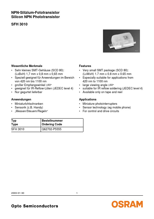
SFH 3010NPN-Silizium-FototransistorSilicon NPN Phototransistor 2003-01-301Wesentliche Merkmale•Sehr kleines SMT-Gehäuse (SCD 80):(LxBxH) 1,7 mm x 0,8 mm x 0,65 mm•Speziell geeignet für Anwendungen im Bereich von 420nm bis 1100nm •großer Empfangswinkel ±80°•geeignet für IR-Reflow-Löten (JEDEC level 4)•Nur gegurtet lieferbar Anwendungen•Miniaturlchtschranken •Sensorik (z.B. Handy)•…Messen/Steuern/Regeln“Typ Type Bestellnummer Ordering Code SFH 3010Q62702-P5555Features•Very small SMT package (SCD 80):(LxWxH) 1.7 mm x 0.8 mm x 0.65 mm •Especially suitable for applications from 420nm to 1100nm•large viewing angle ±80°•suitable for IR reflow soldering (JEDEC level 4)•Available only on tape and reel Applications•Miniature photointerrupters•Sensor technology (eg mobile phone)•For control and drive circuitsGrenzwerte Maximum RatingsBezeichnung Parameter SymbolSymbolWertValueEinheitUnitBetriebs- und Lagertemperatur Operating and storage temperature range Top; T stg– 40…+ 100°CKollektor-Emitterspannung Collector-emitter voltage VCEVCE(t<2min)1530VKollektorstrom Collector current IC15mAKollektorspitzenstrom, τ < 10 µs Collector surge current ICS75mAEmitter-Kollektorspannung Emitter-collector voltage VEC7VVerlustleistung, T A = 25 °C Total power dissipation Ptot130mWWärmewiderstand Sperrschicht - Umgebung bei Montage auf FR4 Platine, Padgröße je 16 mm2 Thermal resistance junction - ambient mounted on PC-board (FR4), padsize 16 mm2 each RthJA585K/W2003-01-3022003-01-303Kennwerte (T A = 25 °C, λ = 950 nm)Characteristics Bezeichnung ParameterSymbol Symbol Wert Value Einheit Unit Wellenlänge der max. Fotoempfindlichkeit Wavelength of max. sensitivityλS max 860nm Spektraler Bereich der Fotoempfindlichkeit S = 10% von S maxSpectral range of sensitivity S = 10% of S maxλ420 (1100)nmBestrahlungsempfindliche Fläche Radiant sensitive area A 0.02mm 2Abmessungen der Chipfläche Dimensions of chip area L ×B L ×W0.38×0.38mm ×mm Halbwinkel Half angleϕ± 80Grad deg.Kapazität CapacitanceV CE = 5 V, f = 1 MHz, E =0C CE1.3pFDunkelstrom Dark currentV CE = 20 V, E =0I CEO2 (≤50)nAFotostrom PhotocurrentE e = 0.5 mW/cm 2,V CE = 5 V I PCE>25µAAnstiegszeit/Abfallzeit Rise and fall timeI C = 1 mA, V CC = 5 V, R L = 1 k Ωt r ,t f7µsKollektrr-Emitter-Sättigungsspannung Collector-emitter saturation voltage I C = 10µAE e = 0.5 mW/cm 2, λ= 950nmV CEsat140mVDirectional CharacteristicsS= f (ϕ)rel2003-01-304Rel. Spectral Sensitivity,PhotocurrentPCE = (A),Dark CurrentCollector-Emitter CapacitanceDark CurrentTotal Power Dissipation2003-01-3052003-01-306Maßzeichnung Package OutlinesMa ße werden wie folgt angegeben: mm (inch) / Dimensions are specified as follows: mm (inch).Published by OSRAM Opto Semiconductors GmbH & Co. OHGWernerwerkstrasse 2, D-93049 Regensburg © All Rights Reserved.Attention please!The information describes the type of component and shall not be considered as assured characteristics.Terms of delivery and rights to change design reserved. Due to technical requirements components may contain dangerous substances. For information on the types in question please contact our Sales Organization.PackingPlease use the recycling operators known to you. We can also help you – get in touch with your nearest sales office.By agreement we will take packing material back, if it is sorted. You must bear the costs of transport. For packing material that is returned to us unsorted or which we are not obliged to accept, we shall have to invoice you for any costs incurred.Components used in life-support devices or systems must be expressly authorized for such purpose! Critical components 1 , may only be used in life-support devices or systems 2 with the express written approval of OSRAM OS.1A critical component is a component usedin a life-support device or system whose failure can reasonably be expected to cause the failure of that life-support device or system, or to affect its safety or effectiveness of that device or system.2Life support devices or systems are intended (a) to be implanted in the human body, or (b) to support and/or maintain and sustain human life. If they fail, it is reasonable to assume that the health of the user may be endangered.Package Epoxy, SmartLED (SCD 80)Colourcolourless, light diffusedPackage marking Collector。
丹福斯高压三梭式水密泵零件和维修手册说明书
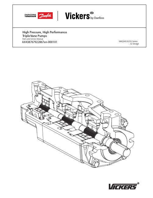
High Pressure, High Performance Triple Vane Pump VMQ3453525SS eries — 32 DesignIncluded in Single STD Seal Kit 02-346523 or Viton Seal Kit 02-346532.Included in Doublt STD Seal Kit 02-346531 or Viton Seal Kit 02-346533.*With double and triple pumps, the orientation of the kits is such that the kit rotation is a reverse of the pump rotation. See tables X1 and X2 for the correct kit rotation relative to the pump rotation.OUTLET BODYFlange Single Shaft Seal Double Shaft SealMounting Inch Port Metric Port Inch Port Metric Port Style Threads Threads Threads ThreadsSAE B998754998748998755998749ISO 100—998756—998757TABLE 1TABLE 2MODEL CODE30TH DESIGN 31ST & 32ND KEY SHAFT DESIGN SHAFT3453525VMQ–***–***–*–*–019970924993377-0019285423453525VMQ–***–***–*–*–029970804993376-001—3453525VMQ–***–***–*–*–039970934993378-0019285473453525VMQ–***–***–*–*–059970944993379-0019285433453525VMQ–***–***–*–*–069970954993380-001—3453525VMQ–***–***–*–*–099970964993381-001—Cartridge Kit Rotation for Left Hand Rotation PumpR= Right Hand RotationL=Left Hand RotationPUMP SHAFT END CENTERCOVER ENDROTATIONKIT ROTATIONKIT ROTATIONKIT ROTATIONTriple (L)(L)(R)(R)*Notes:- A left hand rotation pump has the shaft turning counterclockwisewhen viewed from the input shaft end- When ordering a left hand rotation kit, the part number will have a su x of ‘-L’TABLE X2Cartridge Kit Rotation for Right Hand Rotation PumpR= Right Hand RotationL=Left Hand RotationPUMP SHAFT END CENTER COVER ENDROTATIONKIT ROTATIONKIT ROTATIONKIT ROTATIONTriple (R)(R)(L)(L)*Notes:- A right hand rotation pump has the shaft turning clockwise whenviewed from the input shaft end- When ordering a right hand rotation kit, the part number will not have a su x.TABLE X1TABLE 3MODEL CODE*•CARTRIDGE *•CARTRIDGEENDRT I KOVC)ET I V(ONB(T I KUN)N-AVMQ3453525S***-***-01002-46557402-465569VMQ3453525S***-***-01602-46557502-465570VMQ3453525S***-***-02002-46557602-465571VMQ3453525S***-***-02502-46557802-465572VMQ3453525S***-***-03202-46557702-465573VMQ3453525S***-***-04002-34897402-348981VMQ3453525S***-***-04502-34897502-348982VMQ3453525S***-***-05002-34897602-348983VMQ3453525S***-***-06302-34897702-348984VMQ3453525S***-***-07102-34897802-348985VMQ3453525S***-***-08002-34897902-348986VMQ3453525S***-***-09002-34898002-348987TABLE 4MODEL CODE*•CARTRIDGE *•CARTRIDGECENTER SECTION KIT (BUNA-N)KIT (VITON)VMQ3453525S***-090-***02-46562102-465622VMQ3453525S***-100-***02-46562302-465624VMQ3453525S***-112-***02-46562502-465626VMQ3453525S***-125-***02-46562702-465628VMQ3453525S***-135-***02-46562902-465630VMQ3453525S***-140-***02-46563102-465632VMQ3453525S***-158-***02-46563302-465634TABLE 5MODEL CODE*•CARTRIDGE *•CARTRIDGET I KNDET FHAS)NB(NT I V(OU)N-AT I KVMQ3453525-140-***-***02-34697002-346971VMQ3453525-160-***-***02-34696802-346969VMQ3453525-180-***-***02-34696602-346967VMQ3453525-195-***-***02-34696402-346965VMQ3453525-215-***-***02-34696202-346963Model CodeVMQ3 ** ** 25 *** *** *** * ** * * * * * * * 00 * 0 321 2 3 45 67 811 12 132021 22242526272829323334 359 1014 15 1617 18 192330 31* Verify shaft torque ratings meet or exceed input torque requirementsSeries designation VMQ3 – Vane pump triple series Frame size (front section)45–140-215 cm 3/r (8.54-13.12 in3/r)Frame size(middle section)35–90-158 cm 3/r (5.49-9.64 in3/r)Frame size (rear section)25–10-90 cm 3/r (0.62-5.49 in3/r)Displacement(front section)Frame size 45140–140 cm3/r (8.54 in 3/r)160–160 cm3/r (9.76 in 3/r)180–180 cm3/r (10.98 in 3/r)195–195 cm 3/r (11.89 in 3/r)215–215 cm 3/r (13.12 in 3/r)Displacement(middle section)Frame size 35090–90 cm3/r (5.49 in 3/r)100–100 cm 3/r (6.10 in 3/r)112–112 cm 3/r (6.83 in 3/r)125–125 cm3/r (7.63 in 3/r)135–135 cm3/r (8.24 in 3/r)140–140 cm 3/r (8.54 in 3/r)158–158 cm 3/r (9.64 in3/r)Displacement(rear section)Frame size 25010–10 cm3/r (0.62 in 3/r)016–16 cm3/r (0.98 in 3/r)020–20 cm3/r (1.23 in 3/r)025–25 cm 3/r (1.58 in 3/r)032–32 cm 3/r (1.96 in 3/r)040–40 cm3/r (2.44 in 3/r)045–45 cm3/r (2.75 in 3/r)050–50 cm 3/r (3.05 in 3/r)063–63 cm 3/r (3.84 in 3/r)071–71 cm3/r (4.33 in 3/r)080–80 cm3/r (4.88 in 3/r)090–90 cm 3/r (5.49 in 3/r)Front ange mounting styleA–SAE C 2-boltSAE J744 127-2127,00 (5.000) x 12,4 (0.49) pilot17,6 (0.69) slots on 181,0 (7.13) bolt circle B –ISO 3019/2 125A2HW 2-bolt125,00 (4.921) x 9,2 (0.36) pilot18,1 (0.71) slots on 180,0 (7.09) bolt circleInput shaft type*01–SAE J744 keyed Frame size 45: 38,10 (1.500)02–SAE J744 splined Frame size 45: C-C 03–ISO 3019/2 keyed Frame size 45: 40,00 (1.575)05–SAE J744 keyed Frame size 45: 44,45 (1.750)06–SAE J744 splined Frame size 45: DPort type A–Inlet: SAE J518 4-boltangeFront outlet: SAE J518 4-bolt angeMiddle outlet: SAE J5184-bolt angeRear outlet: SAE J518 4-bolt angeB –Inlet: ISO 6162 4-bolt angeFront outlet: ISO 6162 4-bolt angeMiddle outlet: ISO 6162 4-bolt angeRear outlet: ISO 6162 4-bolt angeFront outlet port positionViewed from cover end of pumpA –Opposite inlet portB –90°CCW to inlet portC –In-line with inlet portD –90°CW to inlet portMiddle outlet port positionViewed from cover end of pumpA –Opposite inlet portB –90°CCW to inlet portC –In-line with inlet portD –90°CW to inlet portRear outlet port positionViewed from cover end of pump453525 units E –Opposite inlet port F –90°CCW to inlet port G –In-line with inlet port H –90°CW to inlet portShaft sealA–Single, primary B–Double, secondary (spring side out)Recommended for wet mount applicationsSeal typeN –Buna N V –VitonW –Buna N with Viton shaft seal(s)Shaft rotationViewed from shaft end of pumpL –Left hand (CCW)R–Right hand (CW)Special features00–NonePaint0–None A –BlueCustomer identi cation–NoneDesign code32–32 designInstallation dimensions remain unchanged for design numbers 31 to 39 inclusive.34 35333230 312928272625242321 222017 18 1914 15 1611 12 139 107 85 61 2 3 4Danfoss Power Solutions is a global manufacturer and supplier of high-quality hydraulic and electric components. We specialize in providing state-of-the-art technology and solutions that excel in the harsh operating conditions of the mobile off-highway market as well as the marine sector. Building on our extensive applications expertise, we work closely with you to ensure exceptional performance for a broad range of applications. We help you and other customers around the world speed up system development, reduce costs and bring vehicles and vessels to market faster.Danfoss Power Solutions – your strongest partner in mobile hydraulics and mobile electrification.Go to for further product information.We offer you expert worldwide support for ensuring the best possible solutions foroutstanding performance. And with an extensive network of Global Service Partners, we also provide you with comprehensive global service for all of our components.Local address:DanfossPower Solutions GmbH & Co. OHG Krokamp 35D-24539 Neumünster, Germany Phone: +49 4321 871 0DanfossPower Solutions ApS Nordborgvej 81DK-6430 Nordborg, Denmark Phone: +45 7488 2222DanfossPower Solutions (US) Company 2800 East 13th Street Ames, IA 50010, USA Phone: +1 515 239 6000DanfossPower Solutions Trading (Shanghai) Co., Ltd.Building #22, No. 1000 Jin Hai Rd Jin Qiao, Pudong New District Shanghai, China 201206Phone: +86 21 2080 6201Danfoss can accept no responsibility for possible errors in catalogues, brochures and other printed material. Danfoss reserves the right to alter its products without notice. This also applies to products already on order provided that such alterations can be made without subsequent changes being necessary in specifications already agreed.All trademarks in this material are property of the respective companies. Danfoss and the Danfoss logotype are trademarks of Danfoss A/S. All rights reserved.Products we offer:•Cartridge valves •DCV directional control valves•Electric converters •Electric machines •Electric motors •Gear motors •Gear pumps •Hydraulic integrated circuits (HICs)•Hydrostatic motors •Hydrostatic pumps •Orbital motors •PLUS+1® controllers •PLUS+1® displays •PLUS+1® joysticks and pedals•PLUS+1® operator interfaces•PLUS+1® sensors •PLUS+1® software •PLUS+1® software services,support and training •Position controls and sensors•PVG proportional valves •Steering components and systems •TelematicsHydro-GearDaikin-Sauer-Danfoss。
SFH 235 FA 光电转换器产品数据表说明书

160
Ptot
mW 140
120
OHF00398
100
80
60
40
20
00
20 40 60 80 ˚C 100
TA
6 Version 1.3 | 2018-05-04
SFH 235 FA
Dimensional Drawing 3)
35.5 (1.398) 33.5 (1.319)
0.75 (0.030) 0.45 (0.018)
Cooling ca. 3.5 K/s typical ca. 2 K/s ca. 5 K/s
50
0 0 20 40 60 80 100 120 140 160 180 200 220 s 240
t
9 Version 1.3 | 2018-05-04
SFH 235 FA
Notes
The evaluation of eye safety occurs according to the standard IEC 62471:2006 (photo biological safety of lamps and lamp systems). Within the risk grouping system of this IEC standard, the LED specified in this data sheet fall into the class exempt group (exposure time 10000 s). Under real circumstances (for exposure time, conditions of the eye pupils, observation distance), it is assumed that no endangerment to the eye exists from these devices. As a matter of principle, however, it should be mentioned that intense light sources have a high secondary exposure potential due to their blinding effect. When looking at bright light sources (e.g. headlights), temporary reduction in visual acuity and afterimages can occur, leading to irritation, annoyance, visual impairment, and even accidents, depending on the situation. Packing information is available on the internet (online product catalog). For further application related informations please visit /appnotes
捷波HA03-F CHN R3.0

捷波®悍马系列主板HA03/HA03-GT用户手册AMD Socket AM2+ K10 处理器主板版本 3.0发布日期:2008年02月版权通告本手册的版权属于制造厂商。
本手册的任何部分,包括产品,软件的描述未经制造厂的书面授权都不能以任何方式或任何手段复制,传播或翻译成任何语言文字。
本手册包含了正常使用该主板所需的一切信息并且我们确信本手册可以适合用户的需求,本公司有权对使用手册的内容进行修改,但是本手册与产品在任何时间的修正与更改不会另行通告,使用手册中的内容如有错误,恳请谅解。
制造厂商提供的使用手册不应当被视作为任何种类,形式的担保。
并且也不会为任何间接的,特殊的,偶然的或相应而生的损害(包括利益损失的伤害,丢失交易、用户数据,交易的中断或与之类似的)负责。
手册版本信息版本手册版本历史发布日期3.0版第三次发布2008年02月包装项目列表5悍马系列HA03/HA03-GT主板5IDE数据线5串行ATA IDE端口数据线5悍马系列HA03主板中文说明书5主板驱动工具光盘5I/O背板贴纸散热方案AMD K10 处理器系列由于科技的日新月异,中央处理器 (CPU) 亦持续往更快速、更高的效能发展。
因此在建置计算机系统时,散热的处理变得越来越重要了,一个适当的散热环境,是让系统更加稳定及长期操作时的关键。
提供适当散热环境的最终目的,则在于维持中央处理器之温度,能低于计算机机壳之最大特定温度。
一个好的风扇,除了要有较高的转速外,适当的散热片面积亦是相当重要的因素。
它可透过其表面之散热片区域的范围,集中来自中央处理器的高热,并透过附加的风扇让热气流传导出去。
除此之外,散热膏亦能有效的将高热由中央处理器传输到散热片。
为了达到散热传导的最佳效果,AMD建议您使用散热膏,并以固定夹将风扇附加在处理器上。
当您为系统选择适当的风扇时,请参考以下网址中AMD所推荐与AMD处理器一起使用之风扇。
/us-en/Processors/DevelopWithAMD/0,,30_2252_869_9460^9515,00.html商标布告所有的品牌,产品,徽标,商标和公司名称都是属于商标或注册商标各自的拥有者。
3G3FV变频器使用手册

3G3FV变频器使用手册最后修订:1996年7月警告手册如果改变不令行通知。
此手册制作精细,但对于手册使用时所造成的身体伤害,Omron不付任何责任。
简介感谢您购买高性能无线变频器。
您现在将拥有一台技术先进,功能繁多,可靠性及安全性强的驱动器。
3G3FV系统驱动器具有高性能直流驱动器的功能,若装入一个反馈编码器,就可拥有交流感应电动机的全部功能。
·在未启动时应向挤压机,起重机和提升机提供150%转矩。
·杰出的速度调节来源于高韧性全自动速度调节系统。
·精确的转矩控制来源于全自动内置流动调节系统。
若没有使用反馈编码器,可开启循环流动向量。
后者包括一种独特的向量控制系统,可确保运行速稳定并将100%转矩降到1 Hz。
结构菜单A部分:初始化请注意●运行时只能使用A1-00或A1-02。
●切换流动失量与V/F控制时,建议先停机。
否则会导致OPE02故障。
●仅当02-03=1及A2-_不空时可进行使用常数的初始化。
参量转换图例:A1-00●按下输入键可降低一个水平。
●按下取消键可升高一个水平。
●按下上下键可在同一水平内选择参数组。
A1-01参数存取A1-01=00 可完成监视功能。
A1-01=01仅可显示A2存储器中的参数。
最多可存储参数。
若A2存储器内没安装02-03,A2_参数上述选择将无法显示。
A1-01=02~04 请参照表格。
使用:快速参考表请注意:·在流动矢量关闭的情况下切换到V/F控制会发生OPE02故障。
确保设备中全部输入输出功能要与V/F兼容。
例如:在返回V/F时若输入一个信息到服务器中就会出现故障。
·改变运行方式重新回到生产默认状态。
A1-04,A1-05:口令输入个人口令的设置及选择:例如设置一个新口令:“1111”1.按照下述路线存取A1-04。
2.口令输入提示。
3.同时按下RESET和MENU键,将1111设置为新口令。
4.显示出A1-05最近使用的口令。
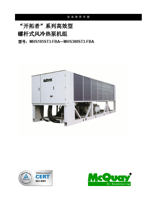
开拓者系列高效型螺杆式风冷热泵安装使用手册
©2012 McQuay SuZhou
4
2. 机组主要部件介绍
电控柜
空气侧换热器 压缩机 风机
水侧换热器
电柜进线孔 ©2012 McQuay SuZhou
5
3. 机组技术参数
机型MHS
名义制冷量
制冷输入总功率
名义制热量
制热输入总功率
电源
最大运行电流
1. 机组型号说明...........................................................................................................................................3 2. 机组主要部件介绍..................................................................................................................................4 3. 机组技术参数..........................................................................................................................................5 4. 运输..........................................................................................................................................................6 5. 吊装..........................................................................................................................................................7
FH303用户手册

版权申明是深圳市吉祥腾达科技有限公司注册商标。
文中提及到的其它商标或商品名称均是他们所属公司的商标或注册商标。
本产品的所有部分,包括配件和软件,其版权属深圳市吉祥腾达科技有限公司所有,在未经过深圳市吉祥腾达科技有限公司许可的情况下,不得任意拷贝、抄袭、仿制或翻译成其它语言。
本手册中的所有图片和产品规格参数仅供参考,随着软件或硬件的升级会略有差异,如有变更,恕不另行通知,如需了解更多产品信息,请浏览我们的网站:目录第1章产品简介 (5)1.1包装清单 (5)1.2面板指示灯及接口说明 (6)第2章产品安装 (8)第3章如何设置上网 (10)3.1正确设置您的计算机网络配置 (10)3.2登录路由器 (15)3.3快速上网 (16)3.4快速加密 (18)第4章高级设置 (19)4.1运行状态 (19)4.2WAN口设置 (21)4.3LAN口设置 (23)4.4MAC克隆 (24)4.5DNS设置 (24)4.6带宽控制 (25)4.7流量统计 (28)4.8WAN速率控制 (29)第5章无线设置 (30)5.1无线基本设置 (30)5.2无线安全 (31)5.3无线桥接 (35)5.4访问控制 (41)5.5连接状态 (43)第6章DHCP服务器 (44)6.1DHCP服务设置 (44)6.2DHCP客户列表 (45)第7章虚拟服务器 (46)7.1端口段映射 (46)7.2DMZ主机 (48)7.3UPNP设置 (49)第8章安全设置 (50)8.1客户端过滤 (50)8.2MAC地址过滤 (52)8.3URL过滤 (54)8.4远程WEB管理 (56)第9章路由设置 (57)9.1路由列表 (57)9.2静态路由 (57)第10章系统工具 (59)10.1网络时间 (59)10.2DDNS (59)10.3备份/恢复设置 (61)10.4恢复出厂设置 (63)10.5升级 (63)10.6重启路由器 (64)10.7修改密码 (64)10.8系统日志 (65)10.9退出登录 (66)附录一:常用无线名词解释 (67)附录二:产品特性 (68)附录三:常见问题解答 (69)附录四:清除无线配置文件 (71)附录五:产品有毒有害物质清单 (74)第1章产品简介感谢您购买腾达300M无线增强型路由器(以下简称路由器)。
丹弗斯变频器参数表.

未安装 工厂推荐值 工厂推荐值 关 0
最小-最大 rpm 根据实际工况要求设置最小(20%) 根据电机铭牌额定转速,略微加大一点 总和 预置速度 0 预置速度 1
3-10.[2] 3-10.[3] 3-10.[4] 3-10.[5] 3-10.[6] 3-10.[7] 3-11 3-12 3-13 3-14 3-15 3-16 3-17 3-18 3-19 3-4* 3-40 3-41 3-42 3-45 3-46 3-47 3-48 3-5* 3-50 3-51 3-52 3-55 3-56 3-57 3-58 3-6* 3-60 3-61 3-62 3-65 3-66 3-67
工厂推荐值(根据工艺要求修改) 无功能 无功能 跳闸
工厂推荐值(根据工艺要求修改) 0 工厂推荐值(根据工艺要求修改) -999999.99
4-55 4-56 4-57 4-58 4-6* 4-60 4-61 4-62 4-63 5-0* 5-00 5-01 5-02 5-1* 5-10 5-11 5-12 5-13 5-14 5-15 5-16 5-17 5-18 5-19 5-20 5-21 5-22 5-23 5-24 5-25 5-26 5-3* 5-30 5-31 5-32 5-33 5-4* 5-40[0] 5-40[1] 5-41 5-42 5-5* 5-50 5-51 5-52 5-53 5-54 5-55
预置参考值[2] 预置参考值[3] 预置参考值[4] 预置参考值[5] 预置参考值[6] 预置参考值[7] 点动速度 加速/减速值 参考值位置 预置相对参考值 参考值来源 1 参考值来源 2 参考值来源 3 相对标定参考值源 点动速度 加减速 1 加减速 1 的类型 斜坡 1 加速时间 斜坡 1 减速时间 加减速 1 S 加减速比率 (加速时)启动 加减速 1 S 加减速比率 (加速时)终止 加减速 1 S 加减速比率 (减速时)启动 加减速 1 S 加减速比率 (减速时)终止 加减速 2 加减速 2 的类型 斜坡 2 加速时间 斜坡 2 减速时间 加减速 2S 加减速比率 (加速时)启动 加减速 2 S 加减速比率 (加速时)终止 加减速 2 S 加减速比率 (减速时)启动 加减速 2 S 加减速比率 (减速时)终止 加减速 3 加减速 3 的类型 斜坡 3 加速时间 斜坡 3 减速时间 加减速 3S 加减速比率 (加速时)启动 加减速 3S 加减速比率 (加速时)终止 加减速 3S 加减速比率 (减速时)启动
火灾报警诺蒂菲尔产品介绍

14
NFS2-3030 联动型控制器
Honห้องสมุดไป่ตู้
先进的探测技术 View技术的高灵敏度的激光探测器。 在恶劣环境中使用的Harsh探测器。 灵敏度度 自动调整的自适应Acclimate探测器。 多种FlashScan协议的探测器。 强大的联动逻辑功能 1000个普通区。 十种逻辑和延时运算功能。 1000个逻辑区,可自定义逻辑运算表达式。 10个故障区,可自定义以故障代码为参数的逻辑表达式。 十个释放区的延时及交叉算法。
4
NOTI·FIRE·NET 智能对等局域网络
传统 消防报警系统设计方案
• 消防总值班室
• 建筑E
232 协议接口
•消
防 值 班 室
• 建筑 A
• 消防值班室
• 消防值班室
• 消防值班室
• 建筑 B
• 建筑 C
• 建筑 D
5
分散控制集中管理式系统设计方案
完全支持 FLASHSCAN 协议 使系统的通讯速度提高五倍以上 - 在一秒中内完成一个回路上的318个器件的 巡检。 - 在两秒内激活159个输出。 – 现场读取设备地址,方便维护 – 集成消防广播电话系统 – 所有端口都采用自保护可恢复结构
13
NFS2-3030 联动型控制器
方便强大的编程功能 标准键盘加功能键盘,如实现面板编程。 自动编程功能。 参数列表式选择,无须记忆。 结构化的CBE设计,更易于编程。 VeriFire Tools离线编程软件。 闪存 远程升级
• 消防总管理中心
Fire System
• 建筑A
• 建筑B
• 建筑C
地下
6
全新的CRT图文系统
SF304中文资料

SF301 - SF30430A SUPER-FAST RECTIFIERFeatures·Case: TO-3P Molded Plastic·Terminals: Solderable per MIL-STD-202,Method 208·Mounting Position: Any ·Polarity: As marked·Approx. Weight: 5.6 gramMechanical DataMaximum Ratings and Electrical CharacteristicsCharacteristicSymbol SF301SF302SF303SF304Unit Maximum Recurrent Peak Reverse Voltage V RRM 50100150200V Maximum RMS Voltage V RSM 3570105140V Maximum DC Blocking VoltageV DC 50100150200V Maximum Average Forward Rectified Current (Total Device)@ T C = 120°C I (AV)30A Peak forward Surge Current 8.3ms half sine-wave superimposed on rated load (JEDEC Method)I FSM300A Maximum Instantaneous Forward @T J =25°C Voltage per leg at I F = 15A (Note 3)@T J = 150°CV F 0.9750.880V Maximum Instantaneous Reverse Current at @T J =25°C Rated DC Blocking Voltage per leg (Note 3)@T J = 150°C I R 10500m A Typical Junction Capacitance (Note 1)C J 80pF Maximum Reverse Recovery Time (Note 2)T rr 35ns Typical Thermal Resistance, Junction to Case R q JC 1.0°C/W Storage and Operating Temperature RangeT J,T STG-65 to +175°CNotes:(1)Measured at 1MHz and applied reverse voltage of 4.0 volts.(2)Reverse recovery test conditions: I F = +0.5A, I R = 1.0A,di/dt = 50A/m s.(3)Pulse width = 300m S, 2% duty cycle.Rating at 25°C ambient temperature unless otherwise specified.Single phase, half wave, 60Hz, resistive or inductive load.For capacitive load, derate current 20%.TO-3PDim Min Max A 3.2 3.5B4.55.4C 21.622.5D 18.921.7E 2.4 2.8G 0.550.81H15.816.2J 1.7 2.7K 3.1Ø 3.3ØL4.2 4.5M5.1 5.7N 0.89 1.5P 2.9 3.3R 11.712.8S5.06.0A BEGJ LMNP K S MHRDCCommon Cathode (no Suffix) shown Add Suffix ‘A’ for Common Anode & change ‘+’ to ‘-’ in illustration above·Plastic Package - UL Flamability Classification 94V-0·High Current Capability ·High Surge Capacity·High Fast Switching Capability < 35 ns ·Low Switching Noise and High ReliabilityI ,A V E R A G E F W D R E C T I F I E D C U R R E N T (A )A V 25507510012515005101520TEMPERATURE (°C)Fig.1,T ,Forward Current Derating CurveC 11010050100150200250300350400NUMBER OF CYCLES AT 60Hz Fig.4Peak Forward Surge CurrentI ,P E A K F W D S U R G E C U R R E N T (A )F S M 110100V ,REVERSE VOLTAGE (VOLTS)Fig.3Typical Junction CapacitanceR 101001000C ,J U N C T I O N C A P A C I T A N C E (p F )J 00.40.81.2 1.62.00.11.010100V ,INSTANTANEOUS FORWARD VOLTAGE (VOLTS)Fig.2Typical Forward CharacteristicsF I ,I N S T A N T A N E O U S F W D R E C T I F I E D C U R R E N T (A )P e r L e gF40801601202000.010.11.010V ,REVERSE VOLTAGE (VOLTS)Fig.5,Typical Reverse CharacteristicsR I ,I N S T A N T A N E O U S R E V E R S E C U R R E N T (µA )R -1.0A-0.25A+0.5A10W Non Inductive50W Non Inductive Notes:1.Rise Time =7ns max,nce =1MW 22pF2.Rise Time =10ns max Source Impedence =50W。
SF3 商品说明书
5-Port Manifold Block
MF5500-4
Manifold Block Ordering Code
Blanking Plate Ordering Code
MF 5500 - 2
Series
Manifold Station
3-Port Manifold Block
MF5300-4
37
SF6000. 1/ 2
“F” FLEXIBLE Series Solenoid / Pneumatic Valves
5/2, 5/3 - 1/2 36mm Body Width Transition Flow 3500 /min (5bar)
SPECIFICATION
Transition Capacity Graph The Material of Parts
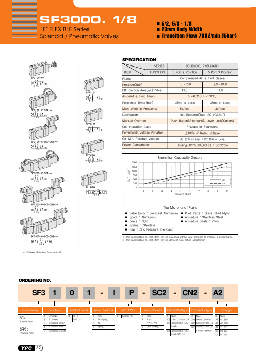
SF3000. 1/ 8
“F” FLEXIBLE Series Solenoid / Pneumatic Valves
5/2, 5/3 - 1/8 23mm Body Width Transition Flow 760 /min (5bar)
SPECIFICATION
Transition Capacity Graph The Material of Parts
ORDERING NO.
SF3 1 0 1 - I P - SC2 - CN2 - A2
Valve Series
SF3 :
SFP3 :
Function
Port Size & Thread Return Method Int/Ext. Pilot
Manual Operator Solenoid Coil Type Connector Type
SFH 5110-40;SFH 5110-38;SFH 5110-30;SFH 5110-36;中文规格书,Datasheet资料

SFH 5110IR-Empfänger für FernbedienungenIR-Receiver for Remote Control SystemsLead (Pb) Free Product - RoHS Compliant2008-10-061BeschreibungSFH 5110 ist ein Infrarot-Empfänger für die Erken-nung von Signalen aus Infrarot-Fernbedienungs-systemen und bestehen aus Fotodiode, Vorver-stärker, automatischer Verstärkungsregelung,Bandpaß-Filter und Demodulator. Das Gehäuse ist zur Unterdrückung des Tageslichteinflusses schwarz eingefärbt.Wesentliche Merkmale•IC mit monolithisch integrierter Fotodiode (Ein-Chip Lösung)•Speziell geeignet für Anwendungen von 940nm•Hohe Empfindlichkeit•Verschiedene Trägerfrequenzen erhältlich •TTL und CMOS kompatibel •Ausgang: aktiv …Low“Anwendungen•Empfänger in Fernbedienungen für TV,Videorecorder, HiFi, Satellitenempfänger und CD-Spieler•Um hohe Sicherheit bei der Datenübertragung zu erreichen, sind fehlerkorrigierende Codes einzusetztenDescriptionSFH 5110 is a IR receiver to detect light from infrared remote control systems. The IC includes photodiode, preamplifier, automatic gain control,bandpass and demodulator. The black-colored package is designed as daylight-cutoff filter.Features•IC with monolithic integrated photodiode (single chip solution)•Especially suitable for applications of 940nm •High sensitivity•Various carrier frequencies available •TTL and CMOS compatibility •Output: active LowApplications•Remote control module for TV sets, VCRs, hi-fi audio receivers, SAT receivers and compact disk players•For safe data transmission error tolerant codes have to be used2008-10-062Typ TypeTrägerfrequ.Carrier Frequency kHz Bestellnr.Ordering CodeSFH 5110-301)1)Mindestbestellmenge 80000 Stück / Minimum order quantity 80000 pieces30Q62702P5088SFH 5110-331)33Q62702P5089SFH 5110-3636Q62702P5090SFH 5110-3838Q62702P5091SFH 5110-401)40Q62702P5092A Maximum RatingsBezeichnung Parameter SymbolSymbolWertValueEinheitUnitBetriebs- und Lagertemperatur Operation and storage temperature range TopTstg– 10…+ 75– 30…+ 100°CBetriebsspannung Supply voltage VCC6.3VAusgangsspannung Output voltage VOUT6.3VAusgangsstrom Output current IOUT3mAVerlustleistungTotal power dissipation, T A≤ 85 °C Ptot50mWEmpfohlener Arbeitsbereich Recommended Operating ConditionsBezeichnung Parameter SymbolSymbolWertValueEinheitUnitmin.typ.max.Betriebstemperatur Operating temperature Top–10–75°CBetriebsspannung Supply Voltage Vcc4.55.0 5.5VKennwerte (T A = 25°C) CharacteristicsBezeichnung Parameter SymbolSymbolWertValueEinheitUnitmin.typ.max.Stromaufnahme, V CC = 5 V, E = 0 Current consumption ICC– 1.3–mAWellenlänge der max. FotoempfindlichkeitWavelength of max. sensitivityλs max–940–nmSpektraler Bereich der Fotoempfindlichkeit1)Spectral range of sensitivityλ830–1100nm2008-10-0632008-10-064Ausgangsspannung Output voltageOutput “High” - (I out = 10 μA)Output “Low” - (I out = 500 μA)V OUT high V OUT low V cc -0.5––––0.5VTrägerfrequenz Carrier frequency SFH 5110-30SFH 5110-33SFH 5110-36SFH 5110-38SFH 5110-40f 0–3033363840–kHzMin. Bestrahlungsstärke (Testsignal, s. Fig.3)Min. Threshold irradiance (test signal, see Fig.3)f = f 0, t p,I = 600 μsE e min–0.350.5mW/m 2Min. Eingangspulsbreite …ON“(Testsignal, s. Fig.3)2)Min. Input pulse width “ON”(test signal, see Fig.3)1)t p,I 6/f O––μsAusgangspulsbreite …ON“(Testsignal, s. Fig.3)Output pulse width “ON” (test signal, see Fig.3, E e = 1 mW/m 2)t p,O t p,I– 6/f O–t p,I+ 6/f Oμs50%-Filterbandbreite, f = f O , E V = 0, V CC = 5 V 50%-Filter bandwidthΔf 50%3–6kHz1)Außerhalb des spezifizierten Bereiches der Fotoempfindlichkeit besitzt der SFH 5110 eine Restempfindlichkeit. D.h.Lichtquellen außerhalb des spezifizierten Wellenlängenbereiches des Sensors können den Baustein beeinflussen und zum Durchschalten führen.1)Beyond the specified spectral range of sensitivity the SFH 5110 has a strongly reduced, but non-zero sensitivity.Light sources with wavelengths outside the spectral range may influence the device and result in switching.2)Die volle Empfindlichkeit wird bei einer Burstlänge von mindestens 6 Pulsen erreicht. Die Reichweite bei Verwendung eines typischen Senders (SFH 4510/SFH 4515, I F = 500 mA) beträgt etwa 30 m.2)A minimum burst length of 6 pulses is necessary for full sensitivity. The transmission distance with a typical transmitter (SFH 4510/SFH 4515, I F = 500 mA) is about 30 m.A Characteristics (cont’d)Bezeichnung ParameterSymbol SymbolWert Value Einheit Unit min.typ.max.Figure1BlockschaltbildBlock DiagramFigure2Externe BeschaltungExternal Circuit2008-10-065Figure3Optisches TestsignalOptical Test SignalAnmerkungen / Notes- Abhängig von den Umgebungsbedingungen, z.B in Form von externen Lichtquellen, elektro-magnetischer Strahlung und Rauschen der Versorgungsspannung, kann es zum sporadischen Durchschalten des Ausgang kommen, selbst wenn kein optisches Signal angelegt wird! Um Fehlinterpretationen der übermittelten Daten zu verhindern, sind fehlerkorrigierende Codes einzusetzen.- Environmental conditions, e.g. external light sources, electromagnetic interference and supply voltage noise , may cause sporadic switching at the output, even without an optical input signal! To avoid misinterpretation of the transmitted data, error tolerant codes must be used.Für weitere Informationen lesen Sie bitte die Application Note des SFH 5110:For further information please read the application note of the SFH 5110:Gerneral Application Note for SFH 511X2008-10-066Relative Spectral Sensitivityf)Vertical Directivity ϕyHorizontal Directivity ϕx2008-10-067MaßzeichnungPackage OutlinesMaße in mm (inch) / Dimensions in mm (inch).2008-10-068LötbedingungenSoldering ConditionsWellenlöten (TTW)(nach CECC 00802)Published byOSRAM Opto Semiconductors GmbHWernerwerkstrasse 2, D-93049 Regensburg© All Rights Reserved.The information describes the type of component and shall not be considered as assured characteristics.Terms of delivery and rights to change design reserved. Due to technical requirements components may contain dangerous substances. For information on the types in question please contact our Sales Organization.PackingPlease use the recycling operators known to you. We can also help you – get in touch with your nearest sales office. By agreement we will take packing material back, if it is sorted. You must bear the costs of transport. For packing material that is returned to us unsorted or which we are not obliged to accept, we shall have to invoice you for any costs incurred.Components used in life-support devices or systems must be expressly authorized for such purpose! Critical components 1 , may only be used in life-support devices or systems 2 with the express written approval of OSRAM OS.1 A critical component is a component usedin a life-support device or system whose failure can reasonably be expected to cause the failure of that life-support device or system, or to affect its safety or effectiveness of that device or system.2 Life support devices or systems are intended (a) to be implanted in the human body, or (b) to support and/or maintain and sustain human life. If they fail, it is reasonable to assume that the health of the user may be endangered.2008-10-069分销商库存信息:OSRAMSFH 5110-40SFH 5110-38SFH 5110-30 SFH 5110-36。
REF3033中文资料

REF3012(1) - 1.25V
OUTPUT VOLTAGE Initial Accuracy NOISE Output Voltage Noise Voltage Noise LINE REGULATION VOUT 1.2475 1.25 1.2525 0.2 V % µVp-p µVrms 190 µV/V
VOLTAGE (V) 1.25 2.048 2.5 3.0 3.3 4.096
DROPOUT VOLTAGE vs LOAD CURRENT 350
IN 1 REF3012 REF3020 REF3025 REF3030 REF3033 REF3040 SOT23-3
300
Dropout Voltage (mV)
250 200 150 100 50 0 0 5 10 15 20 25 30 Load Current (mA)
3
GND
OUT
2
Please be aware that an important notice concerning availability, standard warranty, and use in critical applications of Texas Instruments semiconductor products and disclaimers thereto appears at the end of this data sheet. All trademarks are the property of their respective owners.
ELECTROSTATIC DISCHARGE SENSITIVITY
This integrated circuit can be damaged by ESD. Texas Instruments recommends that all integrated circuits be handled with appropriate precautions. Failure to observe proper handling and installation procedures can cause damage. ESD damage can range from subtle performance degradation to complete device failure. Precision integrated circuits may be more susceptible to damage because very small parametric changes could cause the device not to meet its published specifications.
SUS303F化学成分

优良的耐蚀性及冷加工性能,但303更多地被贴上”易切削”的标签。
具体来说,303中磷硫的含量略高于304,切削加工性能比304好;303Cu则在303基础上添加了铜,变得更加容易切削加工,尤其适合钻孔加工;303F侧重于防腐性能,它的抗腐蚀性能比303Cu强,正常盐雾测试都可超过24小时。
车床件、螺栓、螺母、轴件等,适合自床加工不锈钢不会产生腐蚀、点蚀、锈蚀或磨损。
不锈钢还是建筑用金属材料中强度最高的材料之一。
由于不锈钢具有良好的耐腐蚀性,所以它能使结构部件永久地保持工程设计的完整性。
含铬不锈钢还集机械强度和高延伸性于一身,易于部件的加工制造,可满足建筑师和结构设计人员的需要200系列—铬-镍-锰奥氏体不锈钢300系列—铬-镍奥氏体不锈钢301—延展性好,用于成型产品。
也可通过机械加工使其迅速硬化。
焊接性好。
抗磨性和疲劳强度优于304不锈钢。
302—耐腐蚀性同304,由于含碳相对要高因而强度更好。
303—通过添加少量的硫、磷使其较304更易切削加工。
304—即18/8不锈钢。
GB牌号为0Cr18Ni9。
309—较之304有更好的耐温性。
316—继304之後,第二个得到最广泛应用的钢种,主要用于食品工业、制药行业和外科手术器材,添加钼元素使其获得一种抗腐蚀的特殊结构。
由于较之304其具有更好的抗氯化物腐蚀能力因而也作“船用钢”来使用。
SS316则通常用于核燃料回收装置。
18/10级不锈钢通常也符合这个应用级别。
型号321—除了因为添加了钛元素降低了材料焊缝锈蚀的风险之外其他性能类似304。
400系列—铁素体和马氏体不锈钢。
408—耐热性好,弱抗腐蚀性,11%的Cr,8%的Ni。
409—最廉价的型号(英美),通常用作汽车排气管,属铁素体不锈钢(铬钢)。
410—马氏体(高强度铬钢),耐磨性好,抗腐蚀性较差。
416—添加了硫改善了材料的加工性能。
420—“刃具级”马氏体钢,类似布氏高铬钢这种最早的不锈钢。
Parker-Hannifin 方向控制阀 Series F130CF F130CP 备件列表说明书
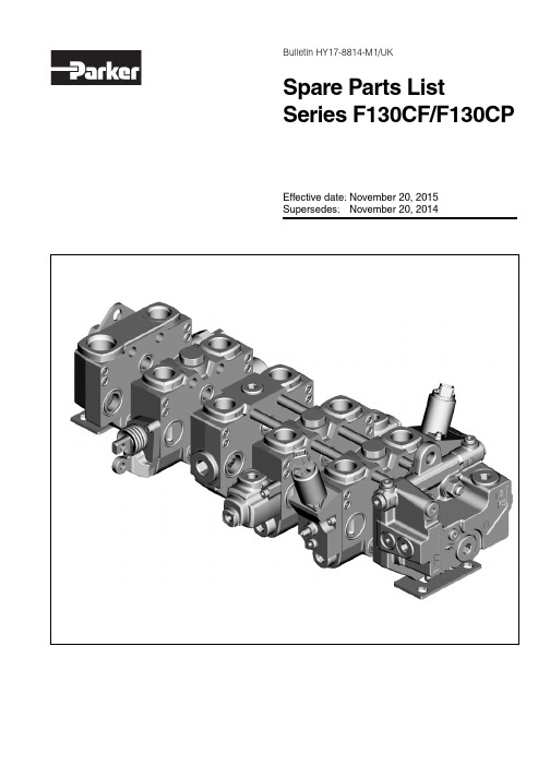
Bulletin HY17-8814-M1/UKSpare Parts List Series F130CF/F130CP Effective date: November 20, 2015 Supersedes: November 20, 2014Directional Control Valves Series F130CF/F130CPBulletin HY17-8814-M1/UKSpare Parts ListConversion factors1 kg = 2.2046 lb 1 N = 0.22481 lbf 1 Nm = 0.10197 kpm 1 bar = 14.504 psi 1 l = 0.21997 UK gallon 1 l = 0.26417 US gallon 1 cm 3 = 0.061024 in 31 m = 3.2808 feet 1 mm= 0.03937 in1°C = (9/5xC°+32)°FThis list of spare parts is designed to give you a good idea of the components included in the product range for valves. T o see precisely which component is used for a specifi c product, you will need to look at the customer specifi cation for the product in question. The customer specifi cation contains a number of entries, and for each entry, a code pressure or fl ow is specifi ed with a code or a number. T o help you fi nd your way around, this list of spare parts contains r eferences to these entries and codes.Codes on the image page of the list of spare parts usually appear in bold and enclosed in a border. The table page contains available spare part sets. The ordering code is the product code that appears in the Part column.The spare part to be used is determined by the fi rst two columns, which c ontain the entry and the code from the customer specifi cation. If these c olumns are empty, the spare part set is valid regardless of the selected code, unless indicated otherwiseThe symbols in the frame below are used in this Spare Parts List to help you fi nd the right tools, the right tor-ques, suitable grease etc.Technical index description1 = Item pos. no. 1.1(2x) = Item pos. no. 1, contains 2 pieces in the kit 1[2] = Item pos. no. 2 already mounted on item pos. no. 1 at delivery.1[2](2x) = Item pos. no. 1 (see above) contains 2 pieces in the kit.Directional Control Valves Series F130CF/F130CPBulletin HY17-8814-M1/UKContentsF130CF-06-SE10-999A 1234560624-224707-005DesignationCustomer ordered markingSerial numberValve serial numbers consist of three groups of digits The fi rst group shows year and week of manufacture:In this example, 0624 means week 24 of 2006The remaining digits are for internal use within ParkerList of contentsPageConventional Inlet Options IPS, PB, L, B, P1B, P2B, T2B, Y , CUI, CUI2, LSI .................................... ..............4Inlet Options IUPS, PB, Y , N3, X3, BEN .......................................................................................6Mid-Inlet Options MIC2 .................................................................................................... ...................8C3, C5, PS, PB, Y ............................................................................ .................10Spool ActuatorsC, B3, SI2, A13, A20, A40, A67, A323,Lever brackets LMA, LMB, LM+A92, LJA, LJB, LJ+A92, LJ+A208, LU, LU2....12ACE .................................................................................................. .................14ACP .................................................................................................. .................16PC30, PC40, EC1, EC2, EC3, EC4, ECS1, ECS2, ECS3, ECS4, A, D, A211..18Spool Section OptionsP A, X2, N2, Y2, N, X, MS, EA, EB .................................................... .................20Outlet OptionsUSP , US, R35, S, YS, T3B, T1B, TP , TPB, TB, TPC, PT , LD ............. .................22Tie rods, Bracket, Intersection seals ................................................ .................24Appendix A: Warnings ......................................................................... .................26Appendix C: Assembly Instructions. Tools ....................................... .................27Appendix D: Phased out ..................................................................... .. (31)This spare parts list is valid for F130 generation 2 only. See productdesignation on the name plate. For spare parts to generation 1 see product information No HY17-8801-M1/UKGeneration 2 has designation in format as shown below:F130CF-XX-XXXX-XXX F130CF-XX-XXXX-XXXX F130CP-XX-XXXX-XXX F130CP-XX-XXXX-XXXXNotice ! Some valves hasn't any designation code stamped. Some valves has the serial number and designation code text line in opposite order than the example above.Name plateDirectional Control Valves Series F130CF/F130CPBulletin HY17-8814-M1/UKPS, PB, L, B, P1B, P2B, T2B, Y, CUI, CUI2, LSIConventional Inlet Options IDirectional Control ValvesBulletin HY17-8814-M1/UKDirectional Control Valves Bulletin HY17-8814-M1/UKSeries F130CF/F130CP Inlet Options IUPS, PB, Y, N3, X3, BENInlet with pump unloadingDirectional Control Valves Bulletin HY17-8814-M1/UKSeries F130CF/F130CP Inlet Options IUSee Customer Specifi cationCode Pos Part Description Remarks / ItemsN3239120199902Check valve9 [6, 7, 8]X3239120199903Plug8, 9BEN229120199904Solenoid valve14 [15, 17]BEN + 1222 + 056760414CCP012A, Coil, 12 VDC16BEN + 2422 + 056760415CCP024A, Coil, 24 VDC16IU159120199905Basic kit11, 13 [12](2x), 18, 20, 21 IU156760017Plug kit M6x1212(2x), 13(2x)IU15393000K067Counter pressure valve22, 23, 24, 25, 27IU159120199907Seal kit8, 12(2x), 20, 24IU15-Plug VSTI1/4EDCF27Directional Control Valves Bulletin HY17-8814-M1/UKSeries F130CF/F130CP Mid-Inlet Options MIC2Directional Control Valves Bulletin HY17-8814-M1/UKSeries F130CF/F130CP Mid-Inlet Options MISee Customer Specifi cationCode Pos Part Description Remarks / ItemsC293-Plug VSTI1EDCF1C293-Plug 16HP5ON-S1C293398000K061Plug (O-ring) 1/2", BSP3C293-Plug VSTI3/4EDCF11C293-Plug 12HP5ON-S11C2936760412Plug kit18 [13(2x), 14, 15, 16, 17]C293301000K831Seal kit13(2x), 14, 15, 16, 17Directional Control ValvesSeries F130CF/F130CP Bulletin HY17-8814-M1/UKC3, C5, PS, PB, YMid-Inlet Options MIa) See page 4a)C3/C5Mid-Inlet Options MISee Customer Specifi cationCode Pos Part Description Remarks / ItemsC3, C593-Plug VSTI1EDCF1C3, C593-Plug 16HP5ON-S1C3, C593-Plug VSTI3/4EDCF13C3, C593-Plug 12HP5ON-S13C393398000K061Plug (O-ring) 1/2", BSP3C3, C593301000K833Blocking plug C3, C58 [5(2x), 6, 7], 10C3, C593-Plug VSTI1/4EDCF10C3, C593301000K835Seal kit5(2x), 6, 7, 10C5936760413Blocking plug, C522C393301000K804Conversion kit C33, 8 [5(2x), 6, 7], 10, 13, 19C593301000K807Conversion kit C5, (80 - 125) bar8 [5(2x), 6, 7], 10, 20, 22C593301000K808Conversion kit C5, (126 - 140) bar8 [5(2x), 6, 7], 10, 20, 22C593301000K809Conversion kit C5, (141 - 160) bar8 [5(2x), 6, 7], 10, 20, 22C593301000K810Conversion kit C5, (161 - 210) bar8 [5(2x), 6, 7], 10, 20, 22C593301000K805Conversion kit C5, (211 - 250) bar8 [5(2x), 6, 7], 10, 20, 22C593301000K811Conversion kit C5, (251 - 280) bar8 [5(2x), 6, 7], 10, 20, 22C593301000K812Conversion kit C5, (281 - 320) bar8 [5(2x), 6, 7], 10, 20, 22C593301000K813Conversion kit C5, (321 - 350) bar8 [5(2x), 6, 7], 10, 20, 22Spool ActuatorsC, B3, SI2, LMA, LMB, LJA, LJB, LU, LU2, A13, A20, A40, A67, A92, A208, A324Spool Actuators ACESpool ActuatorsSee Customer Specifi cationCode Pos Part Description Remarks / ItemsACE509120039065Cylinder kit, BSP15, 16, 17(2x), 18, 19, 20(2x) ACE509120099911Spring kit ACE 5 [4](2x), 7, 8, 9, 10, 11, 12, 13, 14ACE + 1250 + 0591********Solenoid valve, 12 VDC21,22,23,24,33(2x),34,35[31,32] ACE + 2450 + 0591********Solenoid valve, 24 VDC21,22,23,24,33(2x),34,35[31,32] ACE509120099913Spares kit for solenoid valve22, 23, 24, 31, 32, 33(2x), 35 ACE509120099912Seal kit, ACE 5 [4](2x), 15, 17(2x)ACE50-Connector, inlet (P6F-BEAA146)25ACE50-T ube, ø6, L=35 mm (P6T-PN06100)26ACE50-Connector, intermediate (P6F-BTS46)27ACE50-End plug (P6F-BVP46)28ACE50-T ube ø6, L = 89 mm (P6T-PN06100)29ACE506760420Conector kit for 4 sections30 [25(4x), 26(7x), 27(4x), 28, 29]Spool Actuators ACPSpool ActuatorsSee Customer Specifi cationCode Pos Part Description Remarks / ItemsACP + G50 + 049120039063Cylinder kit, BSP15, 16, 17(2x), 18, 19, 20(2x)ACP + U50 + 049120039064Cylinder kit, UNF15, 16, 17(2x), 18, 19, 20(2x)ACP509120099914Spring kit ACP 5 [4](2x), 7, 8, 9, 10, 11, 12, 13, 14, 21 ACP509120099912Seal kit, ACP 5 [4](2x), 15, 17(2x)PC30, PC40, EC1, EC2, EC3, EC4, ECS1, ECS2, ECS3, ECS4, A, D, A211Spool ActuatorsEC1/EC2ECS1/ECS2A-sideEC1/EC2ECS1/ECS2B-sideSpool ActuatorsSee Customer Specifi cationCode Pos Part Description Remarks / ItemsPC30, PC40 + G50 + 046760397Cap kit PC30/40, A or B side, BSP11, 22(2x), 23PC30, PC40 + U50 + 046760399Cap kit PC30/40, A or B side, UNF11, 22(2x), 23PC30, PC40506763308Seal kit PC30, PC4011 (5x)A211 + G59 + 046760398Cap kit A211, A or B side, with5, 6, 11, 22(2x), 24, 30spool stroke limiter, BSPA211 + U59 + 046760400Cap kit A211, A or B side, with5, 6, 11, 22(2x), 24, 30spool stroke limiter, UNFA211596763307Seal kit A2115(2x), 11(2x)a) + G50 + 046763137Cap kit EC, A-side, BSP9(2x), 11, 12(2x), 20 [4, 5, 6]a) + U50 + 046763138Cap kit EC, A-side, UNF9(2x), 11, 12(2x), 20 [4, 5, 6]a) + G50 + 046763134Cap kit EC, B-side, BSP9(2x), 11, 13(2x), 19 [4, 5, 6]a) + U50 + 046763135Cap kit EC, B-side, UNF9(2x), 11, 13(2x), 19 [4, 5, 6]b) + G50 + 046763700Cap kit EC, A-side, BSP9(2x), 11, 12(2x), 16 [4, 5, 6]b) + U50 + 046763698Cap kit EC, A-side, UNF9(2x), 11, 12(2x), 16 [4, 5, 6]b) + G50 + 046763701Cap kit EC, B-side, BSP9(2x), 11, 13(2x), 15 [4, 5, 6]b) + U50 + 046763699Cap kit EC, B-side, UNF9(2x), 11, 13(2x), 15 [4, 5, 6]a), b) + G50 + 04301000K843Seal kit EC*, BSP4(2x), 5(2x), 9(4x), 11(2x)a), b) + U50 + 04301000K822Seal kit EC*, UNF4(2x), 5(2x), 9(4x), 11(2x)EC*1,EC*3,PC3050301000K844Spring pack (5 - 15) bar14EC*2,EC*4,PC4050301000K845Spring pack (7 - 25) bar14A34050S6763546Spring pack (5 - 20) bar14a) + 12 + A50 + 05+ 566763059Solenoid valve, PS25, 12 VDC28(2x), 29 [25, 26, 27]; No c), Amp. conn.a) + 24 + A50 + 05+ 566763060Solenoid valve, PS25, 24 VDC28(2x), 29 [25, 26, 27]; No c), Amp. conn.a) + 12 + D50 + 05+ 566763061Solenoid valve, PS25, 12 VDC28(2x), 32 [25, 26, 27]; No c), Deutsch c.a) + 24 + D50 + 05+ 566763062Solenoid valve, PS25, 24 VDC28(2x), 32 [25, 26, 27]; No c), Deutsch c.a) + 12 + A50 + 05+ 566763328Solenoid valve, PS25MO, 12 VDC28(2x), 29 [25, 26, 27]; With c), Amp. conn.a) + 24 + A50 + 05+ 566763327Solenoid valve, PS25MO, 24 VDC28(2x), 29 [25, 26, 27]; With c), Amp. conn.a)506760507Seal kit PS2525(5x), 26(5x), 27(5x)O + a)55A/B + 50398000K604Pilot restriction "O", Ø1.2 mm18(5x) without damping)N + a)55A/B + 50398000K602Pilot restriction "N", Ø0.9 mm18(5x) Normal dampingH + a)55A/B + 50398000K601Pilot restriction "H", Ø0.6 mm18(5x) Hard dampingb) + 12 + A50 + 05+ 56393000M012Solenoid valve, PVC25, 12 VDC7(2x), 8 [1, 2, 3]; With c), Amp. connection b) + 24 + A50 + 05+ 56393000M024Solenoid valve, PVC25, 24 VDC7(2x), 8 [1, 2, 3]; With c), Amp. connection b) + 12 + D50 + 05+ 56393000D012Solenoid valve, PVC25, 12 VDC7(2x), 31 [1, 2, 3]; With c), Deutsch conn.b) + 24 + D50 + 05+ 56393000D024Solenoid valve, PVC25, 24 VDC7(2x), 31 [1, 2, 3]; With c), Deutsch conn.b) + 12 + A50 + 05+ 56393000N012Solenoid valve, PVC25, 12 VDC7(2x), 8 [1, 2, 3]; No c), Amp. connection b) + 24 + A50 + 05+ 56393000N024Solenoid valve, PVC25, 24 VDC7(2x), 8 [1, 2, 3]; No c), Amp. connection b)50393000K813Seal kit PVC251, 2, 3O + b)55A/B + 506760086Pilot restriction "O", Ø1.2 mm17(5x) without damping (5 dots)N + b)55A/B + 506760083Pilot restriction "N", Ø0.9 mm17(5x) Normal damping (10 dots)H + b)55A/B + 506760080Pilot restriction "H", Ø0.6 mm17(5x) Hard damping (1 dot)-Plug VSTI1/8EDCF4-Plug 4HP5ON-S4Spool Section OptionsEA, EB, N, X, MS, PA, X2, N2, Y2Directional Control Valves Bulletin HY17-8814-M1/UKDirectional Control Valves Bulletin HY17-8814-M1/UKSeries F130CF/F130CP Outlet OptionsUSP, US, R35, S, ST, YS, T3B, T1B, TP, TPB, TB, TPC, PT, LDDirectional Control Valves Bulletin HY17-8814-M1/UKDirectional Control Valves Series F130CF/F130CPBulletin HY17-8814-M1/UKTie rods, Bracket, Intersection sealsOutlet Options(12)Directional Control ValvesSeries F130CF/F130CPBulletin HY17-8814-M1/UKOutlet OptionsSee Customer Specifi cation CodePos PartDescriptionRemarks / ItemsBrackets 301000K866Bracket kit12(6x), 13(2x), 15(2x), 16(6x)Tie rods 9120199921Tie rod kit, valve 1 spool section, 160 mm 14(3x), 12(6x), 16(6x)Tie rods 9120199922Tie rod kit, valve 2 spool sections, 213 mm 14(3x), 12(6x), 16(6x)Tie rods 9120199923Tie rod kit, valve 3 spool sections, 256 mm 14(3x), 12(6x), 16(6x)Tie rods 9120199924Tie rod kit, valve 4 spool sections, 309 mm 14(3x), 12(6x), 16(6x)Tie rods 9120199925Tie rod kit, valve 5 spool sections, 352 mm 14(3x), 12(6x), 16(6x)Tie rods 9120199926Tie rod kit, valve 6 spool sections, 405 mm 14(3x), 12(6x), 16(6x)Tie rods 9120199927Tie rod kit, valve 7 spool sections, 448 mm 14(3x), 12(6x), 16(6x)Tie rods 9120092347Tie rod kit, valve 8 spool sections, 501 mm 14(3x), 12(6x), 16(6x)Tie rods 6760532Tie rod kit, valve 9 spool sections, 544 mm14(3x), 12(6x), 16(6x)Tie rods 6760533Tie rod kit, valve 10 spool sections, 597 mm 14(3x), 12(6x), 16(6x)Tie rods 9120199931Tie rod kit, valve 11 spool sections, 640 mm 14(3x), 12(6x), 16(6x)Tie rods 9120199932Tie rod kit, valve 12 spool sections, 688 mm 14(3x), 12(6x), 16(6x)Standard 301000K851Intersection seals NBR (Nitrile)7(3x), 8(2x), 9(3x), 10, 11(4x)A3008E301000K850Intersection seals FPM (Viton ®)7(3x), 8(2x), 9(3x), 10, 11(4x)Directional Control Valves Series F130CF/F130CPBulletin HY17-8814-M1/UKAppendix A: WarningsDirectional Control Valves Series F130CF/F130CPBulletin HY17-8814-M1/UKAppendix C: Assembly Instructions. ToolsPLD130 is delivered set to the max of its face value (e.g. Required pressure for a PLD130-161-210 can only be adjusted to a value <210).Adjusting to the required level should be done as shown in below instrictions.1. Loosen the lock nut one rev.Counter-clockwise2. Set required pressure value by turning the adjusting screw.3. Hold adjusting screw and fasten lock nut clockwise. Tightening torque 10 Nm.Directional Control Valves Series F130CF/F130CPBulletin HY17-8814-M1/UKAppendix C: Assembly Instructions. ToolsRemoval and mounting of scraper ring4, 51. Remove carefully the old scraper ring (not spring loaded) to avoid damaging of the lever bracket. Use as tool a screwdriver,a nippers or a small hook.2. Clear scraper ring groove and make sure there are no color or paint flakes remaining in the track.3 The scraper ring with associated surfaces in the lever bracket must be oiled.4. Push the new scraper ring in the lever brackets track.Directional Control Valves Series F130CF/F130CPBulletin HY17-8814-M1/UKAppendix C: Assembly Instructions. ToolsCap kits 6760398 (BSP) and 6760400 (UNF) can be installed on both A and B side of valve Measure shown below is valid if NO stroke limit is requiredCap used on the B (spring pack) side of valve.Cap used on the A (spool end) side of valve.Directional Control Valves Series F130CF/F130CPBulletin HY17-8814-M1/UKAppendix C: Assembly Instructions. Tools1. A special tool must be used to engage the manual override function of the solenoid! Use of other tools to attempt to engage or disengage the manual override may not work or may not work when intended.2. When using the manual override function, the solenoid has only on-off functionality and doesn’t operate proportionally as usual. This means, for example, that the solenoid may operate much faster than usual and the unexpected speed could cause crushing or other injuries.3. When using the manual override be certain that all operations of the application, regardless of speed, will not endanger persons or property nearby.4. As always, consult the operations manual for all specifications and functions of the valve. If there are questions contact MCDE.The PS25MO is equipped with a manual override pin in the connector. To actuate the PS25MO a specific tool is needed since the tolerances of the pin is so small that it can be damaged or the pin sticks in actuated position.Please notify that it’s for fault searching only and shall be used as rarely as possible with common sense in mind. If manual override is used humans can be exposed for very dangerous situations. Please read the legal limits before using the manual override.Part number for override tool: 6763001.Directional Control Valves Series F130CF/F130CPBulletin HY17-8814-M1/UKPTAppendix D: Phased outE d . 2015-04-21Your local authorized Parker distributorEMEA Product Information CentreFree phone: 00 800 27 27 5374(from AT , BE, CH, CZ, DE, DK, EE, ES, FI, FR, IE, IL, IS, IT , LU, MT , NL, NO, PL, PT , RU, SE, SK, UK, ZA)US Product Information Centre Toll-free number: 1-800-27 27 537Parker WorldwideEurope, Middle East, AfricaAE – United Arab Emirates, DubaiTel: +971 4 8127100********************AT – Austria, Wiener Neustadt Tel: +43 (0)2622 23501-0*************************AT – Eastern Europe, Wiener NeustadtTel: +43 (0)2622 23501 900****************************AZ – Azerbaijan, Baku Tel: +994 50 22 33 458****************************BE/LU – Belgium, Nivelles Tel: +32 (0)67 280 900*************************BG – Bulgaria, So a Tel: +359 2 980 1344**************************BY – Belarus, Minsk Tel: +48 (0)22 573 24 00************************CH – Switzerland, Etoy Tel: +41 (0)21 821 87 00*****************************CZ – Czech Republic, Klecany Tel: +420 284 083 111*******************************DE – Germany, Kaarst Tel: +49 (0)2131 4016 0*************************DK – Denmark, Ballerup Tel: +45 43 56 04 00*************************ES – Spain, Madrid Tel: +34 902 330 001***********************FI – Finland, Vantaa Tel: +358 (0)20 753 2500parker. ****************FR – France, Contamine s/Arve Tel: +33 (0)4 50 25 80 25************************GR – Greece, Athens Tel: +30 210 933 6450************************HU – Hungary, Budaoers Tel: +36 23 885 470*************************IE – Ireland, Dublin Tel: +353 (0)1 466 6370*************************IT – Italy, Corsico (MI)Tel: +39 02 45 19 21***********************KZ – Kazakhstan, Almaty Tel: +7 7273 561 000****************************NL – The Netherlands, Oldenzaal Tel: +31 (0)541 585 000********************NO – Norway, Asker Tel: +47 66 75 34 00************************PL – Poland, Warsaw Tel: +48 (0)22 573 24 00************************PT – Portugal, Leca da Palmeira Tel: +351 22 999 7360**************************RO – Romania, Bucharest Tel: +40 21 252 1382*************************RU – Russia, Moscow Tel: +7 495 645-2156************************SE – Sweden, Spånga Tel: +46 (0)8 59 79 50 00************************SK – Slovakia, Banská Bystrica Tel: +421 484 162 252**************************SL – Slovenia, Novo Mesto Tel: +386 7 337 6650**************************TR – Turkey, Istanbul Tel: +90 216 4997081************************UA – Ukraine, Kiev Tel: +48 (0)22 573 24 00************************UK – United Kingdom, Warwick Tel: +44 (0)1926 317 878********************ZA – South Africa, Kempton Park Tel: +27 (0)11 961 0700*****************************North AmericaCA – Canada, Milton, Ontario Tel: +1 905 693 3000US – USA, Cleveland (industrial)Tel: +1 216 896 3000US – USA, Elk Grove Village (mobile)Tel: +1 847 258 6200Asia Pacifi cAU – Australia, Castle Hill Tel: +61 (0)2-9634 7777CN – China, Shanghai Tel: +86 21 2899 5000HK – Hong Kong Tel: +852 2428 8008ID – Indonesia, Tangerang Tel: +62 21 7588 1906IN – India, MumbaiTel: +91 22 6513 7081-85JP – Japan, Fujisawa Tel: +81 (0)4 6635 3050KR – South Korea, Seoul Tel: +82 2 559 0400MY – Malaysia, Shah Alam Tel: +60 3 7849 0800NZ – New Zealand, Mt Wellington Tel: +64 9 574 1744SG – Singapore Tel: +65 6887 6300TH – Thailand, Bangkok Tel: +662 186 7000TW – Taiwan, New Taipei City Tel: +886 2 2298 8987VN – Vietnam, Ho Chi Minh City Tel: +84 8 3999 1600South AmericaAR – Argentina, Buenos Aires Tel: +54 3327 44 4129BR – Brazil, Cachoeirinha RS Tel: +55 51 3470 9144CL – Chile, Santiago Tel: +56 2 623 1216MX – Mexico, Toluca Tel: +52 72 2275 4200© 2015 Parker Hanni n Corporation. All rights reserved.。
- 1、下载文档前请自行甄别文档内容的完整性,平台不提供额外的编辑、内容补充、找答案等附加服务。
- 2、"仅部分预览"的文档,不可在线预览部分如存在完整性等问题,可反馈申请退款(可完整预览的文档不适用该条件!)。
- 3、如文档侵犯您的权益,请联系客服反馈,我们会尽快为您处理(人工客服工作时间:9:00-18:30)。
SFH 303SFH 303 FANPN-Silizium-Fototransistor Silicon NPN Phototransistor Wesentliche Merkmaleq Speziell geeignet für Anwendungen im Bereich von 450 nm bis 1100 nm(SFH 303) und bei 880 nm (SFH 303 FA)q Hohe Linearitätq 5 mm-Plastikbauform im LED-Gehäuse q Auch gegurtet und gruppiert lieferbar Anwendungenq Lichtschranken für Gleich- und Wechsellichtbetrieb q Industrieelektronikq “Messen/Steuern/Regeln”Featuresq Especially suitable for applications from 450 nm to 1100 nm (SFH 303) and of 880 nm (SFH 303 FA)q High linearityq 5 mm LED plastic packageq Also available on tape and in groups Applicationsq Photointerrupters q Industrial electronicsq For control and drive circuitsMaße in mm, wenn nicht anders angegeben/Dimensions in mm, unless otherwise specifiedf e o f 6351f e o 063511)Eine Lieferung in dieser Gruppe kann wegen Ausbeuteschwankungen nicht immer sichergestellt werden.Wir behalten uns in diesem Fall die Lieferung einer Ersatzgruppe vor.1)Supplies out of this group cannot always be guaranteed due to unforseeable spread of yield. In this case we will reserve us the right of delivering a substitute group.Typ (*vorher)Type (*formerly)Bestellnummer Ordering Code Typ (*vorher)Type (*formerly)Bestellnummer Type (*formerly)SFH 303Q62702-P957SFH 303 FA (*SFH 303 F)Q62702-P958SFH 303-2Q62702-P228SFH 303 FA-2)(*SFH 303 F)Q62702-P222SFH 303-3Q62702-P229SFH 303 FA-3(*SFH 303 F-3)Q62702-P223SFH 303-41)Q62702-P230SFH 303 FA-4(*SFH 303 F-41))Q62702-P224GrenzwerteMaximum Ratings Bezeichnung DescriptionSymbol SymbolWert Value Einheit Unit Betriebs- und LagertemperaturOperating and storage temperature range T op ;T stg – 55...+ 100°C Löttemperatur bei Tauchlötung Lötstelle ≥ 2 mm vom Gehäuse,Lötzeit t ≤ 5 sDip soldering temperature ≥ 2 mm distance from case bottom, soldering time t ≤ 5 s T S260°CLöttemperatur bei Kolbenlötung Lötstelle ≥ 2 mm vom Gehäuse,Lötzeit t ≤ 3 sIron soldering temperature ≥ 2 mm distance from case bottom, soldering time t ≤ 3 s T S300°CKollektor-Emitterspannung Collector-emitter voltage V CE 50V Kollektorstrom Collector currentI C 50mA Kollektorspitzenstrom,τ <10 µs Collector surge current I CS 100mA Emitter-Basisspannung Emitter-base voltageV EB7VVerlustleistung,T A = 25°C Total power dissipation P tot 200mW Wärmewiderstand Thermal resistanceR thJA375K/WKennwerte (T A = 25°C,λ = 950 nm)Characteristics Bezeichnung DescriptionSymbol SymbolWert ValueEinheit UnitSFH 303SFH 303 FA Wellenlänge der max. Fotoempfindlichkeit Wavelength of max. sensitivityλS max 850870nm Spektraler Bereich der Fotoempfindlichkeit S = 10 % von S maxSpectral range of sensitivity S = 10 % of S maxλ450...1000720...1100nmBestrahlungsempfindliche Fläche Radiant sensitive area A 0.20.2mm 2Abmessung der Chipfläche Dimensions of chip areaL ×B L ×W 0.65×0.650.65×0.65mm × mm Abstand Chipoberfläche zu Gehäuseober-flächeDistance chip front to case surface H4.0...4.64.0...4.6mmHalbwinkel Half angleϕ±20±20Grad deg.Fotostrom der Kollektor-Basis-Fotodiode Photocurrent of collector-base photodiode E e = 0.5 mW/cm 2,V CB = 5 VE v = 1000 Ix, Normlicht/standard light A,V CB = 5 VI PCB I PCB–15.8 4.5–µA µAGrenzwerteMaximum Ratings (cont’d)Bezeichnung DescriptionSymbol SymbolWert Value Einheit UnitDie Fototransistoren werden nach ihrer Fotoempfindlichkeit gruppiert und mit arabischen Ziffern gekennzeichnet.The phototransistors are grouped according to their spectral sensitivity and distinguished by arabian figures.1)I PCEmin ist der minimale Fotostrom der jeweiligen Gruppe 1)I PCEmin is the min. photocurrent of the specified groupKapazität CapacitanceV CE = 0 V,f = 1 MHz,E = 0V CB = 0 V,f = 1 MHz,E = 0V EB = 0 V,f = 1 MHz,E = 0C CE C CB C EB 101521101521pF pF pF Dunkelstrom Dark currentV CE = 10 V,E = 0I CEO2 (≤50)2 (≤50)nABezeichnung DescriptionSymbol SymbolWert ValueEinheit Unit-2-3-4Fotostrom,λ =950 nm PhotocurrentE e = 0.5 mW/cm 2,V CE = 5 V SFH 303:E v = 1000 Ix, Normlicht/standard light A,V CE = 5 VI PCE I PCE 1.0...2.05.2 1.6...3.28.4≥2.513.1mA mA Anstiegszeit/Abfallzeit Rise and fall timeI C = 1 mA,V CC = 5 V,R L = 1 k Ωt r , t f111315µsKollektor-Emitter-SättigungsspannungCollector-emitter saturation voltage I C =I PCEmin 1)× 0.3E e = 0.5 mW/cm 2V CEsat150150150mVStromverstärkung Current gainE e = 0.5 mW/cm 2,V CE = 5 VI PCE I PCB330530830Kennwerte (T A = 25°C,λ = 950 nm)Characteristics (cont’d)Bezeichnung DescriptionSymbol SymbolWert ValueEinheit UnitSFH 303SFH 303 FARelative spectral sensitivity ,SFH 303S rel =f (λ)Output characteristics I C =f (V CE ),I B= Parameter Relative spectral sensitivity ,SFH 303 FA S rel =f (λ)Dark currentI CEO =f (V CE ), E= 0Photocurrent I PCE =f (E e ),V CE = 5 VCapacitanceC =f (VR ),f = 1 MHz,E = 0Directional characteristics S rel =f (ϕ)。