High Integrity Software Volume 1 Requirements and Design
M29W256GL7AN6E

Parallel NOR Flash Embedded Memory M29W256GH, M29W256GLFeatures•Supply voltage–V CC = 2.7–3.6V (program, erase, read)–V CCQ = 1.65–3.6V (I/O buffers)–V PPH = 12V for fast program (optional)•Asynchronous random/page read–Page size: 8words or 16 bytes–Page access: 25, 30ns–Random access: 60ns1, 70, 80ns•Fast program commands: 32-word (64-byte) write buffer•Enhanced buffered program commands: 256-word •Program time–16µs per byte/word TYP–Chip program time: 10s with V PPH and 16s with-out V PPH•Memory organization–Uniform blocks: 256 main blocks, 128-Kbytes or 64-Kwords each•Program/erase controller–Embedded byte/word program algorithms •Program/erase suspend and resume capability–Read from any block during a PROGRAM SUS-PEND operation–Read or program another block during an ERASE SUSPEND operation•Unlock bypass, block erase, chip erase, write to buf-fer and program–Fast buffered/batch programming–Fast block/chip erase •V PP/WP# pin protection–Protects first or last block regardless of block protection settings•Software protection–Volatile protection–Nonvolatile protection–Password protection•Extended memory block–128-word (256-byte) memory block for perma-nent, secure identification–Programmed or locked at the factory or by the customer•Common flash interface–64-bit security code•Low power consumption: Standby and automatic mode•JESD47H-compliant–100,000 minimum PROGRAM/ERASE cycles per block–Data retention: 20 years (TYP)•65nm single-level cell (SLC) process technology •Fortified BGA, TBGA, and TSOP packages •Green packages available–RoHS-compliant–Halogen-free•Automotive device grade (6): temperature –40°C to +85°C (automotive grade certified)•Automotive device grade (3): temperature –40°C to +125°C (automotive grade certified)Note: 1.The 60ns device is available upon customer request.Part Numbering InformationAvailable with extended memory block prelocked by Micron. Devices are shipped from the factory with memory content bits erased to 1. For available options, such as packages or high/low protection, or for further information, contact your Micron sales representative. Part numbers can be verified at . Feature and specifica-tion comparison by device type is available at /products. Contact the factory for devices not found.Table 1: Part Number InformationNotes: 1.80ns if VCCQ = 1.65V to VCC.2.The 60ns device is available upon customer request.3.Automotive qualified, available only with option 6. Qualified and characterized according to AEC Q100 andQ003 or equivalent; advanced screening according to AEC Q001 and Q002 or equivalent.ContentsGeneral Description (7)Signal Assignments (8)Signal Descriptions (23)Memory Organization (24)Memory Configuration (24)Memory Map – 256Mb Density (24)Bus Operations (25)Read (25)Write (25)Standby and Automatic Standby (25)Output Disable (26)Reset (26)Registers (27)Status Register (27)Lock Register (32)Standard Command Definitions – Address-Data Cycles (34)READ Operations (36)READ/RESET Command (36)READ CFI Command (36)AUTO SELECT Operations (37)AUTO SELECT Command (37)Bypass Operations (40)UNLOCK BYPASS Command (40)UNLOCK BYPASS RESET Command (40)Program Operations (41)PROGRAM Command (41)UNLOCK BYPASS PROGRAM Command (41)WRITE TO BUFFER PROGRAM Command (41)UNLOCK BYPASS WRITE TO BUFFER PROGRAM Command (44)WRITE TO BUFFER PROGRAM CONFIRM Command (44)BUFFERED PROGRAM ABORT AND RESET Command (44)PROGRAM SUSPEND Command (44)PROGRAM RESUME Command (45)ENTER and EXIT ENHANCED BUFFERED PROGRAM Command (45)ENHANCED BUFFERED PROGRAM Command (45)ENHANCED BUFFERED PROGRAM ABORT AND RESET Command (48)Erase Operations (49)CHIP ERASE Command (49)UNLOCK BYPASS CHIP ERASE Command (49)BLOCK ERASE Command (49)UNLOCK BYPASS BLOCK ERASE Command (50)ERASE SUSPEND Command (50)ERASE RESUME Command (51)Block Protection Command Definitions – Address-Data Cycles (52)Protection Operations (55)LOCK REGISTER Commands (55)PASSWORD PROTECTION Commands (55)NONVOLATILE PROTECTION Commands (55)NONVOLATILE PROTECTION BIT LOCK BIT Commands (57)VOLATILE PROTECTION Commands (57)EXTENDED MEMORY BLOCK Commands (57)EXIT PROTECTION Command (58)Device Protection (59)Hardware Protection (59)Software Protection (59)Volatile Protection Mode (60)Nonvolatile Protection Mode (60)Password Protection Mode (61)Common Flash Interface (62)Power-Up and Reset Characteristics (66)Absolute Ratings and Operating Conditions (69)DC Characteristics (71)Read AC Characteristics (73)Write AC Characteristics (76)Accelerated Program, Data Polling/Toggle AC Characteristics (83)Program/Erase Characteristics (85)Package Dimensions (86)Revision History (89)Rev. B – 05/13 (89)Rev. A – 05/12 (89)List of FiguresFigure 1: Logic Diagram (7)Figure 2: 44-Pin SO (Top View) (8)Figure 3: 44-Pin SO (Top View) (8)Figure 4: 48-Pin TSOP (Top View) (9)Figure 5: 48-Pin TSOP (Top View) (10)Figure 6: 48-Pin TSOP (Top View) (10)Figure 7: 48-Pin TSOP (Top View) (11)Figure 8: 56-Pin TSOP (Top View) (12)Figure 9: 56-Pin TSOP (Top View) (12)Figure 10: 56-Pin TSOP (Top View) (13)Figure 11: 48-Ball Fortified BGA and 48-Ball TBGA (15)Figure 12: 48-Ball Fortified BGA and 48-Ball TBGA (16)Figure 13: 48-Ball Fortified BGA and 48-Ball TBGA (17)Figure 14: 48-Ball Fortified BGA and 48-Ball TBGA (18)Figure 15: 64-Ball Fortified BGA and 64-Ball TBGA (19)Figure 16: 64-Ball Fortified BGA and 64-Ball TBGA (20)Figure 17: 64-Ball Fortified BGA and 64-Ball TBGA (21)Figure 18: 64-Ball Fortified BGA and 64-Ball TBGA (22)Figure 19: Data Polling Flowchart (29)Figure 20: Toggle Bit Flowchart (30)Figure 21: Status Register Polling Flowchart (31)Figure 22: Lock Register Program Flowchart (33)Figure 23: WRITE TO BUFFER PROGRAM Flowchart (43)Figure 24: ENHANCED BUFFERED PROGRAM Flowchart (47)Figure 25: Program/Erase Nonvolatile Protection Bit Algorithm (56)Figure 26: Software Protection Scheme (61)Figure 27: Power-Up Timing (66)Figure 28: Reset AC Timing – No PROGRAM/ERASE Operation in Progress (67)Figure 29: Reset AC Timing During PROGRAM/ERASE Operation (68)Figure 30: AC Measurement Load Circuit (70)Figure 31: AC Measurement I/O Waveform (70)Figure 32: Random Read AC Timing (8-Bit Mode) (74)Figure 33: Random Read AC Timing (16-Bit Mode) (74)Figure 34: Page Read AC Timing (16-Bit Mode) (75)Figure 35: WE#-Controlled Program AC Timing (8-Bit Mode) (77)Figure 36: WE#-Controlled Program AC Timing (16-Bit Mode) (78)Figure 37: CE#-Controlled Program AC Timing (8-Bit Mode) (80)Figure 38: CE#-Controlled Program AC Timing (16-Bit Mode) (81)Figure 39: Chip/Block Erase AC Timing (8-Bit Mode) (82)Figure 40: Accelerated Program AC Timing (83)Figure 41: Data Polling AC Timing (84)Figure 42: Toggle/Alternative Toggle Bit Polling AC Timing (8-Bit Mode) (84)Figure 43: 56-Pin TSOP – 14mm x 20mm (86)Figure 44: 64-Pin TBGA – 10mm x 13mm (87)Figure 45: 64-Ball Fortified BGA – 11mm x 13mm (88)List of TablesTable 1: Part Number Information (2)Table 2: Signal Descriptions (23)Table 3: 256Mb, Blocks[255:0] (24)Table 4: Bus Operations (25)Table 5: Status Register Bit Definitions (27)Table 6: Operations and Corresponding Bit Settings (28)Table 7: Lock Register Bit Definitions (32)Table 8: Block Protection Status (32)Table 9: Standard Command Definitions – Address-Data Cycles, 8-Bit and 16-Bit (34)Table 10: Read Electronic Signature (37)Table 11: Block Protection (39)Table 12: Block Protection Command Definitions – Address-Data Cycles, 8-Bit and 16-Bit (52)Table 13: Extended Memory Block Address and Data (57)Table 14: V PP/WP# Functions (59)Table 15: Query Structure Overview (62)Table 16: CFI Query Identification String (62)Table 17: CFI Query System Interface Information (63)Table 18: Device Geometry Definition (63)Table 19: Primary Algorithm-Specific Extended Query Table (64)Table 20: Security Code Area (65)Table 21: Power-Up Wait Timing Specifications (66)Table 22: Reset AC Specifications (67)Table 23: Absolute Maximum/Minimum Ratings (69)Table 24: Operating Conditions (69)Table 25: Input/Output Capacitance1 (70)Table 26: DC Current Characteristics (71)Table 27: DC Voltage Characteristics (72)Table 28: Read AC Characteristics (73)Table 29: WE#-Controlled Write AC Characteristics (76)Table 30: CE#-Controlled Write AC Characteristics (79)Table 31: Accelerated Program and Data Polling/Data Toggle AC Characteristics (83)Table 32: Program/Erase Characteristics (85)General DescriptionThe M29W is an asynchronous, uniform block, parallel NOR Flash memory device man-ufactured on 65nm single-level cell (SLC) technology. READ, ERASE, and PROGRAM op-erations are performed using a single low-voltage supply. Upon power-up, the device defaults to read array mode.The main memory array is divided into uniform blocks that can be erased independent-ly so that valid data can be preserved while old data is purged. PROGRAM and ERASE commands are written to the command interface of the memory. An on-chip program/erase controller simplifies the process of programming or erasing the memory by taking care of all special operations required to update the memory contents. The end of a PROGRAM or ERASE operation can be detected and any error condition can be identi-fied. The command set required to control the device is consistent with JEDEC stand-ards.CE#, OE#, and WE# control the bus operation of the device and enable a simple con-nection to most microprocessors, often without additional logic.The M29W supports asynchronous random read and page read from all blocks of the array. It features a write to buffer program capability that improves throughput by pro-gramming a buffer of 32 words in one command sequence. Also, in x16 mode, the en-hanced buffered program capability improves throughput by programming 256 words in one command sequence. The device V PP /WP# signal enables faster programming.The device contains a 128-word (x16) and 256-byte (x8) extended memory block. The user can program this additional space and then protect it to permanently secure the contents. The device also features different levels of hardware and software protection to secure blocks from unwanted modification.Figure 1: Logic DiagramVV A[23:0]V /WP#DQ[14:0]SSSignal Assignments Figure 2: 44-Pin SO (Top View)1 2 3 4 5 6 7 8 9 10 11 12 13 14 15 16 17 18 19 20 21 2244 43 42 41 40 39 38 37 36 35 34 33 32 31 30 29 28 27 26 25 24 23RFU RY/BY#A17A7A6A5A4A3A2A1A0CE#V SSOE#D0D8D1D9D2D10D3D11RST#WE#A8A9A10A11A12A13A14A15A16BYTE#V SSDQ15/A-1DQ7DQ14DQ6DQ13DQ5DQ12DQ4V CC Notes: 1.A17 = A[MAX].2.A-1 is the least significant address bit in x8 mode.Figure 3: 44-Pin SO (Top View)1 2 3 4 5 6 7 8 9 10 11 12 13 14 15 16 17 18 19 20 21 2244 43 42 41 40 39 38 37 36 35 34 33 32 31 30 29 28 27 26 25 24 23RST# A18 A17 A7 A6 A5 A4 A3 A2 A1 A0 CE# V SS OE# D0 D8 D1 D9 D2 D10 D3 D11WE#RFUA8A9A10A11A12A13A14A15A16BYTE#V SSDQ15/A-1DQ7DQ14DQ6DQ13DQ5DQ12DQ4V CC Notes: 1.A18 = A[MAX].2.A-1 is the least significant address bit in x8 mode.Figure 4: 48-Pin TSOP (Top View)1 2 3 4 5 6 7 8 9 10 11 12 13 14 15 16 17 18 19 20 21 22 23 2448 47 46 45 44 43 42 41 40 39 38 37 36 35 34 33 32 31 30 29 28 27 26 25A15A14A13A12A11A10A9A8RFURFUWE# RST#RFURFU RY/BY#RFUA17A7A6A5A4A3A2A1A16BYTE#V SSDQ15/A-1DQ7DQ14DQ6DQ13DQ5DQ12DQ4V CCDQ11DQ3DQ10DQ2DQ9DQ1DQ8DQ0OE#V SSCE#A0 Notes: 1.A17 = A[MAX].2.A-1 is the least significant address bit in x8 mode. Figure 5: 48-Pin TSOP (Top View)1 2 3 4 5 6 7 8 9 10 11 12 13 14 15 16 17 18 19 20 21 22 23 2448 47 46 45 44 43 42 41 40 39 38 37 36 35 34 33 32 31 30 29 28 27 26 25A15A14A13A12A11A10A9A8RFURFUWE# RST#RFURFU RY/BY#A18A17A7A6A5A4A3A2A1A16BYTE#V SSDQ15/A-1DQ7DQ14DQ6DQ13DQ5DQ12DQ4V CCDQ11DQ3DQ10DQ2DQ9DQ1DQ8DQ0OE#V SSCE#A0 Notes: 1.A18 = A[MAX].2.A-1 is the least significant address bit in x8 mode.Figure 6: 48-Pin TSOP (Top View)1 2 3 4 5 6 7 8 9 10 11 12 13 14 15 16 17 18 19 20 21 22 23 2448 47 46 45 44 43 42 41 40 39 38 37 36 35 34 33 32 31 30 29 28 27 26 25A15A14A13A12A11A10A9A8A19A20WE#RST#RFU V PP/WP# RY/BY#A18A17A7A6A5A4A3A2A1A16BYTE#V SSDQ15/A-1DQ7DQ14DQ6DQ13DQ5DQ12DQ4V CCDQ11DQ3DQ10DQ2DQ9DQ1DQ8DQ0OE#V SSCE#A0 Notes: 1.A20 = A[MAX].2.A-1 is the least significant address bit in x8 mode.Figure 7: 48-Pin TSOP (Top View)1 2 3 4 5 6 7 8 9 10 11 12 13 14 15 16 17 18 19 20 21 22 23 2448 47 46 45 44 43 42 41 40 39 38 37 36 35 34 33 32 31 30 29 28 27 26 25A15A14A13A12A11A10A9A8A19A20WE#RST#A21 V PP/WP# RY/BY#A18A17A7A6A5A4A3A2A1A16 BYTE#V SSDQ15/A-1 DQ7DQ14 DQ6DQ13 DQ5DQ12 DQ4V CCDQ11 DQ3DQ10 DQ2DQ9DQ1DQ8DQ0OE#V SSCE#A0Notes: 1.A21 = A[MAX].2.A-1 is the least significant address bit in x8 mode. Figure 8: 56-Pin TSOP (Top View)1 2 3 4 5 6 7 8 9 10 11 12 13 14 15 16 17 18 19 20 21 22 23 24 25 26 27 2856 55 54 53 52 51 50 49 48 47 46 45 44 43 42 41 40 39 38 37 36 35 34 33 32 31 30 29RFURFUA15A14A13A12A11A10A9A8A19A20WE#RST#A21 V PP/WP# RY/BY#A18A17A7A6A5A4A3A2A1RFURFURFURFUA16BYTE#V SSDQ15/A-1DQ7DQ14DQ6DQ13DQ5DQ12DQ4V CCDQ11DQ3DQ10DQ2DQ9DQ1DQ8DQ0OE#VSSCE#A0RFUV CCQ Notes: 1.A21 = A[MAX].2.A-1 is the least significant address bit in x8 mode.Figure 9: 56-Pin TSOP (Top View)1 2 3 4 5 6 7 8 9 10 11 12 13 14 15 16 17 18 19 20 21 22 23 24 25 26 27 2856 55 54 53 52 51 50 49 48 47 46 45 44 43 42 41 40 39 38 37 36 35 34 33 32 31 30 29RFUA22A15A14A13A12A11A10A9A8A19A20WE#RST#A21 V PP/WP# RY/BY#A18A17A7A6A5A4A3A2A1RFURFURFURFUA16BYTE#V SSDQ15/A-1DQ7DQ14DQ6DQ13DQ5DQ12DQ4V CCDQ11DQ3DQ10DQ2DQ9DQ1DQ8DQ0OE#VSSCE#A0RFUV CCQ Notes: 1.A22 = A[MAX].2.A-1 is the least significant address bit in x8 mode.Figure 10: 56-Pin TSOP (Top View)1 2 3 4 5 6 7 8 9 10 11 12 13 14 15 16 17 18 19 20 21 22 23 24 25 26 27 2856 55 54 53 52 51 50 49 48 47 46 45 44 43 42 41 40 39 38 37 36 35 34 33 32 31 30 29A23A22A15A14A13A12A11A10A9A8A19A20WE#RST#A21 V PP/WP# RY/BY#A18A17A7A6A5A4A3A2A1RFURFURFURFUA16BYTE#V SSDQ15/A-1DQ7DQ14DQ6DQ13DQ5DQ12DQ4V CCDQ11DQ3DQ10DQ2DQ9DQ1DQ8DQ0OE#VSSCE#A0RFUV CCQ Notes: 1.A23 = A[MAX].2.A-1 is the least significant address bit in x8 mode.Figure 11: 48-Ball Fortified BGA and 48-Ball TBGANotes: 1.A[17] = A[MAX].2.A-1 is the least significant address bit in x8 mode.Figure 12: 48-Ball Fortified BGA and 48-Ball TBGANotes: 1.A[18] = A[MAX].2.A-1 is the least significant address bit in x8 mode.Figure 13: 48-Ball Fortified BGA and 48-Ball TBGANotes: 1.A[20] = A[MAX].2.A-1 is the least significant address bit in x8 mode.Figure 14: 48-Ball Fortified BGA and 48-Ball TBGANotes: 1.A[21] = A[MAX].2.A-1 is the least significant address bit in x8 mode.Figure 15: 64-Ball Fortified BGA and 64-Ball TBGANotes: 1.A[20] = A[MAX].2.A-1 is the least significant address bit in x8 mode.Figure 16: 64-Ball Fortified BGA and 64-Ball TBGANotes: 1.A[21] = A[MAX].2.A-1 is the least significant address bit in x8 mode.3.Pads D8 and F1 are not connected (NC) on the M29W640GT and M29W640GB devices.Figure 17: 64-Ball Fortified BGA and 64-Ball TBGANotes: 1.A[22] = A[MAX].2.A-1 is the least significant address bit in x8 mode.Figure 18: 64-Ball Fortified BGA and 64-Ball TBGANotes: 1.A[23] = A[MAX].2.A-1 is the least significant address bit in x8 mode.Signal DescriptionsThe signal description table below is a comprehensive list of signals for this device fami-ly. All signals listed may not be supported on this device. See Signal Assignments for in-formation specific to this device.Table 2: Signal DescriptionsTable 2: Signal Descriptions (Continued)Memory OrganizationMemory ConfigurationThe main memory array is divided into 128KB or 64KW uniform blocks. Memory Map – 256Mb DensityTable 3: 256Mb, Blocks[255:0]Bus OperationsTable 4: Bus OperationsNotes: 1.Typical glitches of less than 5ns on CE#, WE#, and RST# are ignored by the device and donot affect bus operations.2.H = Logic level HIGH (V IH); L = Logic level LOW (V IL); X = HIGH or LOW.3.If WP# is LOW, then the highest or the lowest block remains protected, depending online item.4.Data input is required when issuing a command sequence or when performing datapolling or block protection.ReadBus READ operations read from the memory cells, registers, or CFI space. To acceleratethe READ operation, the memory array can be read in page mode where data is inter-nally read and stored in a page buffer.Page size is 8 words (16 bytes) and is addressed by address inputs A[2:0] in x16 busmode and A[2:0] plus DQ15/A-1 in x8 bus mode. The extended memory blocks and CFIarea do not support page read mode.A valid READ operation requires setting the appropriate address on the address inputs,taking CE# and OE# LOW, and holding WE# HIGH. Data I/O signals output the value. WriteBus WRITE operations write to the command interface. A valid WRITE operation re-quires setting the appropriate address on the address inputs. These are latched by thecommand interface on the falling edge of CE# or WE#, whichever occurs last. Values ondata I/O signals are latched by the command interface on the rising edge of CE# orWE#, whichever occurs first. OE# must remain HIGH during the entire operation. Standby and Automatic StandbyWhen the device is in read mode, driving CE# HIGH places the device in standby modeand drives data I/Os to High-Z. Supply current is reduced to standby (I CC2), by holdingCE# within V CC ±0.3V.During PROGRAM or ERASE operations the device continues to use the program/erasesupply current (I CC3) until the operation completes.Automatic standby enables low power consumption during read mode. When CMOSlevels (VCC ± 0.3 V) drive the bus and following a READ operation and a period of inac-tivity specified in DC Characteristics, the memory enters automatic standby as internalsupply current is reduced to ICC2. Data I/O signals still output data if a READ operationis in progress. Depending on load circuits connected with data bus, VCCQ, can have anull consumption when the memory enters automatic standby.Output DisableData I/Os are High-Z when OE# is HIGH.ResetDuring reset mode the device is deselected and outputs are High-Z. The device is in re-set mode when RST# is LOW. Power consumption is reduced to standby level independ-ently from CE#, OE#, or WE# inputs.RegistersStatus RegisterTable 5: Status Register Bit DefinitionsNotes: 1.The status register can be read during PROGRAM, ERASE, or ERASE SUSPEND operations;the READ operation outputs data on DQ[7:0].2.For a PROGRAM operation in progress, DQ7 outputs the complement of the bit beingprogrammed. For a READ operation from the address previously programmed success-fully, DQ7 outputs existing DQ7 data. For a READ operation from addresses with blocksto be erased while an ERASE SUSPEND operation is in progress, DQ7 outputs 0; uponsuccessful completion of the ERASE SUSPEND operation, DQ7 outputs 1. For an ERASEoperation in progress, DQ7 outputs 0; upon either operation's successful completion,DQ7 outputs 1.3.After successful completion of a PROGRAM or ERASE operation, the device returns toread mode.4.During erase suspend mode, READ operations to addresses within blocks not beingerased output memory array data as if in read mode. A protected block is treated thesame as a block not being erased. See the Toggle Flowchart for more information.5.During erase suspend mode, DQ6 toggles when addressing a cell within a block beingerased. The toggling stops when the program/erase controller has suspended the ERASEoperation. See the Toggle Flowchart for more information.6.When DQ5 is set to 1, a READ/RESET command must be issued before any subsequentcommand.Table 6: Operations and Corresponding Bit SettingsNotes: 1.Unspecified data bits should be ignored.2.DQ7# for buffer program is related to the last address location loaded.Figure 19: Data Polling FlowchartNotes: 1.Valid address is the address being programmed or an address within the block beingerased.2.Failure results: DQ5 = 1 indicates an operation error; DQ1 = 1 indicates a WRITE TO BUF-FER PROGRAM ABORT operation.Figure 20: Toggle Bit FlowchartNote: 1.Failure results: DQ5 = 1 indicates an operation error; DQ1 = 1 indicates a WRITE TO BUF-FER PROGRAM ABORT operation.Figure 21: Status Register Polling FlowchartLock RegisterTable 7: Lock Register Bit DefinitionsNotes: 1.The lock register is a 16-bit, one-time programmable register. DQ[15:3] are reserved andare set to a default value of 1.2.The password protection mode lock bit and nonvolatile protection mode lock bit cannotboth be programmed to 0. Any attempt to program one while the other is programmedcauses the operation to abort, and the device returns to read mode. The device is ship-ped from the factory with the default setting.Table 8: Block Protection StatusNotes: 1.Nonvolatile protection bit lock bit: when cleared to 1, all nonvolatile protection bits areunlocked; when set to 0, all nonvolatile protection bits are locked.2.Block nonvolatile protection bit: when cleared to 1, the block is unprotected; when setto 0, the block is protected.3.Block volatile protection bit: when cleared to 1, the block is unprotected; when set to 0,the block is protected.Figure 22: Lock Register Program FlowchartNotes: 1.Each lock register bit can be programmed only once.2.See the Block Protection Command Definitions table for address-data cycle details.Standard Command Definitions – Address-Data Cycles Table 9: Standard Command Definitions – Address-Data Cycles, 8-Bit and 16-BitTable 9: Standard Command Definitions – Address-Data Cycles, 8-Bit and 16-Bit (Continued)Notes: 1. A = Address; D = Data; X = "Don't Care;" BAd = Any address in the block; N = Number ofbytes to be programmed; PA = Program address; PD = Program data; Gray shading = Notapplicable. All values in the table are hexadecimal. Some commands require both a com-mand code and subcode.2.These cells represent READ cycles (versus WRITE cycles for the others).3.AUTO SELECT enables the device to read the manufacturer code, device code, block pro-tection status, and extended memory block protection indicator.4.AUTO SELECT addresses and data are specified in the Electronic Signature table and theExtended Memory Block Protection table.5.For any UNLOCK BYPASS ERASE/PROGRAM command, the first two UNLOCK cycles areunnecessary.6.BAd must be the same as the address loaded during the WRITE TO BUFFER PROGRAM3rd and 4th cycles.7.WRITE TO BUFFER PROGRAM operation: maximum cycles = 68(x8) and 36 (x16). UNLOCKBYPASS WRITE TO BUFFER PROGRAM operation: maximum cycles = 66 (x8), 34 (x16).WRITE TO BUFFER PROGRAM operation: N + 1 = bytes to be programmed; maximumbuffer size = 64 bytes (x8) and 32 words (x16).8.For x8, A[MAX:5] address pins should remain unchanged while A[4:0] and A-1 pins areused to select a byte within the N + 1 byte page. For x16, A[MAX:5] address pins shouldremain unchanged while A[4:0] pins are used to select a word within the N + 1 wordpage.9.The following is content for address-data cycles 256 through 258: BAd (FE) - Data; BAd(FF) - Data; BAd (00) - 29.10.BLOCK ERASE address cycles can extend beyond six address-data cycles, depending onthe number of blocks to erase.READ OperationsREAD/RESET CommandThe READ/RESET (F0h) command returns the device to read mode and resets the errorsin the status register. One or three bus WRITE operations can be used to issue theREAD/RESET command.To return the device to read mode, this command can be issued between bus WRITEcycles before the start of a PROGRAM or ERASE operation. If the READ/RESET com-mand is issued during the timeout of a BLOCK ERASE operation, the device requires upto 10μs to abort, during which time no valid data can be read.This command will not abort an ERASE operation while in erase suspend.READ CFI CommandThe READ CFI (98h) command puts the device in read CFI mode and is only valid whenthe device is in read array or auto select mode. One bus WRITE cycle is required to issuethe command.Once in read CFI mode, bus READ operations will output data from the CFI memoryarea (Refer to the Common Flash Interface for details). A READ/RESET command mustbe issued to return the device to the previous mode (read array or auto select ). A sec-ond READ/RESET command is required to put the device in read array mode from autoselect mode.AUTO SELECT OperationsAUTO SELECT CommandAt power-up or after a hardware reset, the device is in read mode. It can then be put inauto select mode by issuing an AUTO SELECT (90h) command or by applying V ID to A9.Auto select mode enables the following device information to be read:•Electronic signature, which includes manufacturer and device code information asshown in the Electronic Signature table.•Block protection, which includes the block protection status and extended memoryblock protection indicator, as shown in the Block Protection table.Electronic signature or block protection information is read by executing a READ opera-tion with control signals and addresses set, as shown in the Read Electronic Signaturetable or the Block Protection table, respectively.Auto select mode can be used by the programming equipment to automatically match adevice with the application code to be programmed.Three consecutive bus WRITE operations are required to issue an AUTO SELECT com-mand. The device remains in auto select mode until a READ/RESET or READ CFI com-mand is issued.The device cannot enter auto select mode when a PROGRAM or ERASE operation is inprogress (RY/BY# LOW). However, auto select mode can be entered if the PROGRAM orERASE operation has been suspended by issuing a PROGRAM SUSPEND or ERASE SUS-PEND command.To enter auto select mode by appling VID to A9, see the Read Electronic Signature tableand the Block Protection table.Auto select mode is exited by performing a reset. The device returns to read mode un-less it entered auto select mode after an ERASE SUSPEND or PROGRAM SUSPENDcommand, in which case it returns to erase or program suspend mode.Table 10: Read Electronic Signature。
斑马技术公司DS8108数字扫描仪产品参考指南说明书

高端存储Xio介绍

Intelligent High Capacity Drive Packing Structure(这 个 架构) Minimize Drive Vibration and Maximize Cooling Design( 降 动 却 故
Three Types 10 HDD Drive 20 HDD Drive 10 HDD +10 SSD
Capacity
Price
Performance : 200,000 IOPS on Hyper ISE 3U Capacity(容量) : Unlimited Scale out Price(价格) : Best Price per IOPS
ISE 2 Generation Image
ISE 2 Chassis
Xio 高端存储设备
高效高速免维护存储产品源动力 来自于 ISE智能存储单元 (Intelligent Storage Element)
2
CPU和存储之间的矛盾
CPU Storage
Time •
• 随着CPU能力的增强,传统的存储系统却没有得到相应比例的提高
•
Over time CPU processing capability has increased at a faster pace than traditional storage arrays
(20ea x 900GB, SAS 10K)
Super Capacity Module
Max 7 Hours “Cache Write-Back Protection”
19
Power & Cooler
Air Vent Air Vent
Redundant Power 20
情报检索与计算机信息检索

2. 文献
• 记录有知识的一切载体。即用文字、 图形、符号、声频、视频等技术手段 记录人类知识的一种载体。 • 文献的范围很广。 古代:甲骨文、碑刻、竹简、帛书 是文献。 现代:图书、报纸、期刊 现今:机读资料、缩微制品、电子 出版物。
7
•文献的级次(按信息的加工程度划分)
• 零次文献信息资源——指尚未被记录下来, 只是通过口头携带和传播的信息资源。零次 信息资源的出现和传递带有极大的偶然性。 其特点是鲜活、生命力旺盛。 • 一次文献信息资源—— 指经加工或粗略加 工的原始信息资源,如正在研究或创造过程 中产生的信息,包括会议记录、论文报告、 统计报表、专利等。其特点是比较零散,系 统性不强,半包括所有的主要内容。
一文献的基本信息摘录下来,供人们间接
地了解、识别该文献。
• 下面,我们分别对不同文献情报源的著
录特征及其识别方法进行讲述。
18
图书:
•
图书的著录项目包括书名、著者,
出版项(出版地、出版社、出版年)、 总页码等。
19
目录
20
• Journalism, literature and modernity :from Hazlitt to Modernism . (1)Campbell, Kate.(2) Edinburgh :Edinburgh University Press,c2000 (3) • (1)书名 • (2)著者(编者) • (3)出版项(包括出版地,出版社,出 版年)
33
文摘
34
• CAD of waveguide low-pass filters for statellite applications. (1)W.Hauth,R. Keller, U.Rosenberg(ANT Nachrichtentech. GmbH, Backnang,West Germany(2)Conference Proceedings:17th European Microwave ConferenceMLCROWAVE 87, Rome,Italy,7-11 Sept. 1987(3)(Tunbridge Wells, UK: Microwave Exhibitions&Publishers 1987),P. 137-41(4) • (1)论文名称 题录 • (2)著者和著者单位 • (3)会议录名称、会议地点、开会时间 • (4)会议录出版情况及论文起止页码
2005奥迪a4 1.8t轿车技术规格说明书
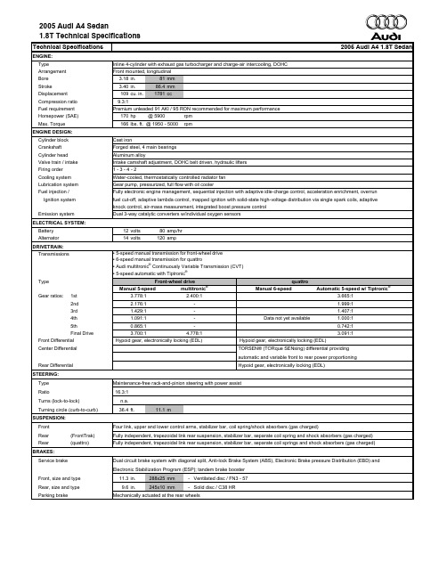
ENGINE:Type Inline 4-cylinder with exhaust gas turbocharger and charge-air intercooling, DOHC Arrangement Front mounted, longitudinal Bore 3.18in.81mm Stroke 3.40in.86.4mm Displacement 109cu. in.1781ccCompression ratio 9.3:1Fuel requirement Premium unleaded 91 AKI / 95 RON recommended for maximum performanceHorsepower (SAE) 170hp @ 5900rpm Max. Torque 166lbs. ft. @ 1950 - 5000rpmENGINE DESIGN:Cylinder block Cast ironCrankshaft Forged steel, 4 main bearings Cylinder head Aluminum alloyValve train / intake Intake camshaft adjustment, DOHC belt driven, hydraulic lifters Firing order 1 - 3 - 4 - 2Cooling system Water-cooled, thermostatically controlled radiator fan Lubrication system Gear pump, pressurized, full flow with oil coolerFuel injection /Fully electronic engine management, sequential injection with adaptive idle-charge control, acceleration enrichment, overrun Ignition system fuel cut-off, adaptive lambda control, mapped ignition with solid-state high-voltage distribution via single spark coils, adaptive knock control, air-mass measurement, integrated boost pressure control Emission system Dual 3-way catalytic converters w/individual oxygen sensorsELECTRICAL SYSTEM:Battery 12volts 80amp/hr Alternator 14volts120ampDRIVETRAIN:TransmissionsType Front-wheel drivequattroManual 5-speedmultitronic ®Manual 6-speedAutomatic 5-speed w/ Tiptronic ®Gear ratios:1st 3.778:1 2.400:13.665:12nd 2.176:1- 1.999:13rd 1.429:1- 1.407:14th 1.091:1-Data not yet available1.000:15th 0.865:1-0.742:1Final Drive3.700:14.778:13.091:1Front Differential Hypoid gear, electronically locking (EDL)Hypoid gear, electronically locking (EDL)Center DifferentialTORSEN® (TORque SENsing) differential providingautomatic and variable front to rear power proportioningRear Differential Hypoid gear, electronically locking (EDL)STEERING:Type Maintenance-free rack-and-pinion steering with power assist Ratio16.3:1Turns (lock-to-lock)n.a.Turning circle (curb-to-curb) 36.4ft.11.1mSUSPENSION:Front Four link, upper and lower control arms, stabilizer bar, coil spring/shock absorbers (gas charged)Rear (FrontTrak)Fully independent, trapezoidal link rear suspension, stabilizer bar, separate coil spring and shock absorbers (gas charged)Rear (quattro)Fully independent, trapezoidal link rear suspension, stabilizer bar, separate coil springs and shock absorbers (gas charged)BRAKES:Service brakeDual circuit brake system with diagonal split, Anti-lock Brake System (ABS), Electronic Brake pressure Distribution (EBD) and Electronic Stabilization Program (ESP); tandem brake boosterFront, size and type 11.3in.288x25mm - Ventilated disc / FN3 - 57Rear, size and type 9.6in.245x10mm- Solid disc / C38 HRParking brakeMechanically actuated at the rear wheels▪ 5-speed manual transmission for front-wheel drive ▪ 6-speed manual transmission for quattro▪ Audi multitronic ® Continuously Variable Transmission (CVT)▪ 5-speed automatic with Tiptronic ®WHEELS:Optional 16" (CA1)Optional 17" (C1X)Size7J x 167.5J x 17Offset42 mm45 mmWeight9,600 g / 21 lbs11,800 g / 26 lbsType Cast alloy Cast alloyTIRES:Optional 16" (H9P)Optional 17" (H8A) or (HG6)Size215 / 55235 / 45Speed rating H Y or HConstruction Radial RadialLoad Index9194Brand / Type (all approved)Pirelli P6 Four Seasons Dunlop SP 9090 (Performance)Michelin MXM4Michelin Pilot Primacy (Performance)-Conti Sport Contact 2 (Performance)BODY:Material Unitized steel structure with integrated aluminum and magnesium componentsCorrosion protection All steel parts are 100% dual-side zinc-galvanized. (12-year limited warranty against corrosion perforation)CAPACITIES:Front wheel drive quattro Engine oil 4.2qt.4liter 4.2qt.4literFuel tank18.5gal. 70liter17.4gal. 66literCooling system 6.9qt. 6.5liter 6.9qt. 6.5literEXTERIOR DIMENSIONS:Front wheel drive quattro Wheelbase104.3in.2650mm104.3in.2650mmTrack:front / rear60.2in.1528mm/60.1in.1526mm60.2in.1528mm/ 60.1in.1526mm Overall length179.0in.4547mm179.0in.4547mmOverall width / with mirrors69.5in.1766mm/76.3in.1937mm69.5in.1766mm / 76.3in.1937mm Height (unloaded)56.2in.1428mm56.2in.1428mmGround clearance (loaded) 4.2in.106mm 4.2in.106mmCurb weight:man. / auto.3252lbs.1475kg/3362in.1525kg3406lbs.1545kg /3550lbs.1610kg Distribution: % front / rear 60 / 4060 / 4058 / 4259 / 41 Drag coefficient: Front / quattro Cw = 0.30 / 0.31Frontal Area = 2.14 sq.m.INTERIOR DIMENSIONS (SAE measurements):Seating Capacity5EPA class CompactHead room front / rear38.4in.976mm/37.24in.946mmw/sunroof front / rear37.3in.948mm/37.09in.942mmShoulder room front / rear55.1in.1400mm/53.43in.1357mmLeg room front / rear41.3in.1050mm/34.25in.870mmInterior volume front / rear50.7cu. ft./39.4cu. ft.103.5= total of cu. ft (including trunk volume)Luggage Capacity13.4cu. ft.PERFORMANCE:Front wheel drive quattroManual 5-speed multitronic®Manual 6-speed Automatic 0-50 mph (0-80kmh) 5.8sec. 5.8sec. 6.1sec. 6.4sec.0-60 mph (0-100 km/h)7.8sec.7.8sec.8.1sec.8.5sec.1/4 mile16.2sec.15.9sec.16.2sec.16.7sec.Top speed Top speed is electronically limited at 130 MPH (208 km/h)FUEL ECONOMY: EPA estimateFront wheel drive quattroManual 5-speed multitronic®Manual 6-speed Automatic City22mpg23mpg21mpg20mpg Highway31mpg29mpg30mpg28mpg Combined25mpg25mpg24mpg23mpgFUEL ECONOMY: Canadian EstimateManual 5-speed multitronic®Manual 5-speed Automatic City liters/100km10.2liters/100km11.2liters/100km11.7 liters/100km Highway liters/100km7.3liters/100km7.2liters/100km7.6 liters/100kmENGINE:Type Aluminum, 90 degree V6 with variable intake manifold, continuous camshaft adjustment, balance shaft, DOHC Arrangement Front mounted, longitudinal Bore 3.25in.82.5mm Stroke 3.65in.92.8mm Displacement 182cu. in.2976ccCompression ratio 10.1 : 1Fuel requirement Premium unleaded 91 AKI / 95 RON recommended for maximum performanceHorsepower (SAE) 220hp @ 6300rpm Torque 221lbs. ft. @ 3200rpmENGINE DESIGN:Cylinder block High integrity aluminum cylinder block with cast-in thin wall gray iron liners Crankshaft Forged steel Cylinder head Aluminum alloyValve train / intake DOHC chain driven, hydraulic valve lifters, two-stage variable intake manifold Firing order 1 - 4 - 3 - 6 - 4 - 5Cooling system Water-cooled, thermostatically controlled radiator fanLubrication system Gear pump, pressurized, full flow with oil coolerFuel injection /Fully electronic engine management utilizing Bosch Motronic ® 7.1.1., sequential injection with adaptive idle-charge control, Ignition system acceleration enrichment, overrun fuel cut-off, adaptive lambda control, mapped ignition with solid-state high-voltage distribution via single spark coils, cylinder selective adaptive knock control with two sensors Emission system Dual 3-way catalytic converters w/individual oxygen sensorsELECTRICAL SYSTEM:Battery 12volts 80amp/hr Alternator 14volts120ampDRIVETRAIN:TransmissionsType Front-wheel drive quattromultitronic ®Manual 6-speedAutomatic 5-speed w/ Tiptronic ®Gear ratios:1st 2.400:1 3.500:1 3.665:12nd - 1.889:1 1.999:13rd - 1.320:1 1.407:14th - 1.034:1 1.000:15th -0.857:10.742:16th -0.730:1-Final Drive4.778:14.111:13.091:1Front Differential Hypoid gear, electronically locking (EDL)Hypoid gear, electronically locking (EDL)Center Differential- TORSEN® (TORque SENsing) differential providingautomatic and variable front to rear power proportioningRear Differential - Hypoid gear, electronically locking (EDL)STEERING:Type Maintenance-free rack-and-pinion steering with power assist Ratio16.3:1Turns (lock-to-lock)n.a.Turning circle (curb-to-curb) 36.4ft.11.1mSUSPENSION:Front Four link, upper and lower control arms, stabilizer bar, coil spring/shock absorbers (gas charged)Rear (FrontTrak)Fully independent, trapezoidal link rear suspension, stabilizer bar, separate coil spring and shock absorbers (gas charged)Rear (quattro)Fully independent, trapezoidal link rear suspension, stabilizer bar, separate coil springs and shock absorbers (gas charged)BRAKES:Service brakeDual circuit brake system with diagonal split, Anti-lock Brake System (ABS), Electronic Brake pressure Distribution (EBD) and Electronic Stabilization Program (ESP); tandem brake boosterFront, size and type 12.3in.312x25mm - Ventilated disc / FN3 - 57Rear, size and type 10in.255x12mm - Solid disc / C38 HRParking brakeMechanically actuated at the rear wheels▪ 6-speed manual transmission▪ Audi multitronic ® Continuously Variable Transmission (CVT)▪ 5-speed automatic with Tiptronic ®WHEELS:Standard 16" (C2F)Optional 17" (C1X)Size7J x 167.5J x 17Offset42 mm45 mmWeight10,000 g / 22 lbs11,800 g / 26 lbsType Cast alloy Cast alloyTIRES:Standard 16" (H9P)Optional 17" (H8A) or (HG6) Size215 / 55235 / 45Speed rating H Y or HConstruction Radial RadialLoad Index9194Brand / Type (all approved)Pirelli P6 Four Seasons Dunlop SP 9090 (Performance)Michelin MXM4Michelin Pilot Primacy (Performance)-Conti Sport Contact 2 (Performance)BODY:Material Unitized steel structure with integrated aluminum and magnesium componentsCorrosion protection All steel parts are 100% dual-side zinc-galvanized. (12-year limited warranty against corrosion perforation)CAPACITIES:Front wheel drive quattro Engine oil 5.8qt. 5.5liter 5.8qt. 5.5literFuel tank18.5gal. 70liter17.4gal. 66literCooling system9.5qt.9liter9.5qt. 9literEXTERIOR DIMENSIONS:Front wheel drive quattro Wheelbase104.3in.2650mm104.3in.2650mmTrack:front / rear60.2in.1528mm/60.1in.1526mm60.2in.1528mm/ 60.1in.1526mm Overall length179.0in.4547mm179.0in.4547mmOverall width / with mirrors69.5in.1766mm/76.3in.1937mm69.5in.1766mm / 76.3in.1937mm Height (unloaded)56.2in.1428mm56.2in.1428mmGround clearance (loaded) 4.2in.106mm 4.2in.106mmCurb weight man. / auto.--/3462lbs.1570kg3583lbs.1625kg3627lbs.1645kg Distribution % front / rear 61/3958 / 4259 / 41 Drag coefficient Cw = 0.31Frontal Area = 2.18 sq. m.INTERIOR DIMENSIONS (SAE measurements):Seating Capacity5EPA class CompactHead room front / rear38.4in.976mm/37.24in.946mmw/sunroof front / rear37.3in.948mm/37.09in.942mmShoulder room front / rear55.1in.1400mm/53.43in.1357mmLeg room front / rear41.3in.1050mm/34.25in.870mmInterior volume front / rear50.7cu. ft./39.4cu. ft.103.5= total of cu. ft (including trunk volume)Luggage Capacity13.4cu. ft.PERFORMANCE:Front wheel drive quattromultitronic®Manual 6-speed Automatic 0-50 mph (0-80kmh) 5.1sec. 5.2sec. 5.8sec.0-60 mph (0-100 km/h) 6.9sec. 6.9sec.7.7sec.1/4 mile15.1sec.15.2sec.15.7sec.Top speed Top speed is electronically limited at 130 MPH (208 km/h)FUEL ECONOMY: EPA estimateFront wheel drive quattromultitronic®Manual 6-speed Automatic City20mpg17mpg18mpgHighway28mpg26mpg25mpgCombined23mpg21mpg21mpgFUEL ECONOMY: Canadian Estimatemultitronic®Manual 6-speed Automatic City11.5liters/100km13.5liters/100km12.8liters/100km Highway8.1liters/100km8.7liters/100km8.4liters/100km。
壳体设计规范
Non Structural
Motor-sport Transaxle
Tractor Transaxle牵引车驱动桥
These are the main components for transferring speed and torque in a transmission 在变速箱结构中,这些是用于传递速度和扭矩主要组件。 As a result they impart the following type of loads on the casing 齿轮和轴从下面几个方面影响作用到壳体上的作用力: Separating Loads are effectively trying to push the each shaft and gear apart. 分离载荷(径向力)有效地将每个轴和齿轮推开。 Tangential Loads act normal to the base circle are a result of the gears reacting against each other. 垂直于基圆的切向力是齿轮之间相互作用的结果 Axial Loads act along the rotating axis of the gear and shaft. 轴向载荷沿齿轮和轴的轴向传递。 Helical gears over spur gears will result in having to consider axial load effects.The larger the helix angle the larger the load. Other gear forms that impart axial loads include bevel and hypoid gearing 斜齿轮与直齿轮相比,必须考虑轴向载荷的影响。螺旋角越大轴向载荷越大。锥齿轮和准双曲面 齿轮也必须考虑轴线载荷的影响
Sysmex CA-600系统产品介绍说明书

Resetting the standard, again.Introducing the Sysmex CA-600 Systems:Reliability and convenience come standard./diagnostics2Built on one standard,to deliver the nextAdvance your hemostasis lab with confidence with the Sysmex CA-600 SystemsThe Sysmex CA-600 Systems share a proven design that drives proven performanceProven reliability for uninterrupted testingWith nearly a year between unscheduled service visits on the Sysmex CA-500 Systems,1 Sysmex CA-series systems offer a history of providing consistently efficient workflow and uninterrupted test results for your physicians.Proven history of #1-ranked serviceWhen you do have an unscheduled service visit, you can be confident that Siemens Healthineers will service your system quickly and efficiently. That’s why, year after year, IMV ServiceTrak rates Siemens Healthineers with the “highest overall service performance,” based on 46 individual service criteria.2Proven economy with two model configurations Some labs need routine testing. Others need routine and specialty testing. With models custom-tailored to the needs of each, labs get the ideal solution. The Sysmex CA-620 System offers clotting testing methodology for laboratories that primarily perform routine tests; the Sysmex CA-660 System offers clotting, chromogenic,* and immunologic* testing for laboratories that require a broader test menu and perform specialty testing. Proven technology for accuracy and confidenceWith more than 5,000 active Sysmex CA-500 Systems installed worldwide,† you can be confident that thedetection principles found in the Sysmex CA-600 Systems represent proven testing accuracy and confidence.The Sysmex® CA-600 Systems build upon the proven technology and reliability of the Sysmex CA-500 Series Systems, offering peace of mind and easy integration into your laboratory. And, as is standard with thesolutions offered by Siemens Healthineers, you can be sure that we will offer various instruments to meet individual needs. That’s why the Sysmex CA-600 Systems are available in two models.1A ccording to internal data.2B ased on ServiceTrak study data from IMV from service years 2007–2011. IMV provides database and market information for products and services for managers in the analytical, clinical diagnostics, biotechnology, life sciences, and medical imaging industries. ServiceTrak is a telephone survey among section supervisors, laboratory managers, and technologists from hospitals across the United States.* Offered on Sysmex CA-660 System only.†As of April 2012, the Siemens Healthineers active installed base exceeded 5400 systems.3BFT™ II SystemSemiautomated dual-channel coagulometer with turbodensito-metric detection, ideal for low-volume labs performing routine coagulation tests.The standard for savingyour time and moneyThe Siemens Healthineers family of solutions offers a systematic, end-to-end approach specially designed to meet your individualized testing needsAs your testing needs grow, we have you covered. Our family of scalable hemostasis instruments represents our commitment to offer solutions that meet the needs of any-sized lab.• W hether your lab requires low-volume routine testing, high-volume specialty testing, or multiple instruments at several locations, we have the solution for you.• O ur cross-platform reagents and consumables,comparable reference ranges, and test cutoff values on all BCS® XP and Sysmex CA and CS systems enable your lab to realize significant improvements in labor efficiency and cost savings.Just some of the standard benefits • C ross-platform use of reagents, controls, and calibrators improves convenience, offers cost savings, and reduces waste for more efficient labor utilization.• T he systems provide consistent monitoring of patients from lab to lab, with one D-dimer cutoff value and results that correlate with the entire Siemens Healthineers family of hemostasis systems.• A single point of contact for all your hemostasis needs supports convenient ordering and service coordination.The Siemens Healthineers portfolio of hemostasis systemsSysmex CA-600 Systems Compact, fully automatedcoagulation analyzers that offer a variety of configurations for clotting, chromogenic,* andimmunologic* methods. Sysmex CS-2500 SystemUnique, mid-volume solution featuring Preanalytical Sample Integrity (PSI™) technology and an advanced third-generationcap-piercing option.Sysmex CS-5100 SystemHigh-volume, fully automated solution featuring PSI technology and full automation connectivityoptions.BCS® XP SystemAuto-start, random-access analyzer offering clotting, chromogenic,immunologic, and aggregation-based assays for both routine and specialty testing in an economical footprint.4Big performance from thesmallest instrument in its class 3123123Automated daily maintenance and sample probe rinsing • R equires minimal daily maintenance and no monthly maintenance downtime •R educes hands-on time through minimal maintenance proceduresRemovable reagent trays • R educes hands-on time with convenient and easily removable reagent trays• E nables hands-off reagent handlingThree different detection principles • R epresents the current state-of-the-art testing methodology by offering clotting, chromogenic,* and immunologic* detection principles in true random access•I mproves workflow by consolidating testing Routine and STAT sample processing • O ffers PT test results in 7 minutes and D-dimer results in 9 minutes • E xpedites STAT sample testing5456456User-friendly display with color LCD • O ffers easy-to-use system handling through intuitive menu structure and tilted color touchscreen• F acilitates easier viewing of reaction curves • I mproves querying of patient resultsHandheld two-dimensional bar-code reader • S aves time and supports accuracy by automating the data-entry process for calibrator and control values • S implifies patient result trackingSample bar-code reader • E nsures the quality and integrity of patient records with an automated, positive sample ID process • L everages the convenience of your LIS by facilitating secure and accurate result transfersBroad testing menu • S upports your most frequently used specialty tests with innovative reagents, including INNOVANCE® Antithrombin,* INNOVANCE D-Dimer* Diagnostic confidence • P rovides uniform D-dimer* results with a single cutoff value of 0.50 mg/L FEU for the exclusion of PE/DVT on all Siemens Healthineers hemostasis systems3Based on a comparison of low-volume instrument dimensions (Height × Weight × Depth) as listed in CAP Today, January 2017.* Offered on Sysmex CA-660 System only.6Four reasons to upgradeto the Sysmex CA-600 Systems—today* Offered on Sysmex CA-660 System only.†† D-dimer throughput is 40% faster when compared to the CA-500 Systems.‡‡Compared to Sysmex CA-500 Systems.Economical operation Save time and money:• T he most economical testing solution is usually the one best tailored to your needs. With the Sysmex CA-620System for routine testing and the Sysmex CA-660 System adding specialty testing, labs get exactly what they need.• T he systems are so easy to learn and use that costly classroom training is not required, maximizing staff availability and ensuring efficient workflow.• T he Siemens Healthineers commitment to cross-platform reagents, quality control, and consumables reduces waste and saves time through streamlined ordering and maintenance.• W ith nearly a year between service visits, you can be confident that the system will deliver consistent uptime.Efficient workflowReduce hands-on time and increase walkaway ability:• A utomated probe rinse eliminates manual steps.• S imultaneous analysis of results frees up time.• I ncreased D-dimer throughput enables physicians to quickly assess a patient’s risk of DVT/PE ††.• H andheld two-dimensional bar-code reader simplifies the data entry process for ISI, control and calibrator values, lot numbers, and expiry information. • S ample bar-code reader provides simplified sample ID processing and enables security and integrity of patient records.Ecological impactMake a big impact with the smallest footprint: • 25% less power consumption.‡‡• M inimal consumables needed—only CA Clean I, CA Clean II, and reaction tubes.• O nly one reaction tube used per test.Excellent correlationConsistently monitor your patients, from lab to lab:• R esults correlate with the entire line of Siemens Healthineers hemostasis systems.• Consistent result provide confidence.A partner as committed to your success as you areThe world leader in hemostasis testingSiemens Healthineers is one of the world’s largest provider ofhemostasis solutions. Our partnership with Sysmex Corporationgives us the combined expertise to anticipate the needs of ourcustomers and deliver the complete and integrated portfolio ofadvanced solutions that customers need.Siemens Customer CareOur Customer Care program truly expands thetraditional definition of “service.” From pre-purchaseand throughout the lifecycle of your instrument,Siemens Customer Care acts as a seamless extension ofyour lab with a comprehensive portfolio of personalizedsolutions, proactive services, and proven expertise toanticipate your challenges and meet your needs.From highly skilled field engineers and workflow expertsto experienced education and customer servicespecialists, we are focused on delivering solutions tohelp you reach the next level of operational efficiency.INNOVANCE ReagentsReagent quality is a critical factor in establishing trust and confidence in any hemostasis testing system. That’s why our comprehensive portfolio of INNOVANCE reagents provides the quality you need to support physicians in making sound diagnostic and therapeutic decisions.Personalized Education Plan (PEPconnect)Available exclusively from Siemens Healthineers as part of the Customer Care program, PEPconnect is the only virtual competency-based education solution in the industry that can be tailored to meet the individual needs of your employees. Our innovative approach to personalized education for the Sysmex CA-600 Systems does not require disruptive, off-site training or traveling, allowing employees to train on their own instruments as their schedule allows.7BCS, BFT, Dade, INNOVANCE, Innovin, and all associated marks aretrademarks of Siemens Healthcare Diagnostics Inc. Sysmex is a trademark of Sysmex Corporation. All other trademarks and brands are the property of their respective owners.On account of certain regional limitations of sales rights and service availability, we cannot guarantee that all products included in thisbrochure are available through the Siemens sales organization worldwide. Availability and packaging may vary by country and is subject to change without prior notice. Some/All of the features and products described herein may not be available in the United States.The information in this document contains general technical descriptions of specifications and options as well as standard and optional features, which do not always have to be present in individual cases.Siemens reserves the right to modify the design, packaging, specifications, and options described herein without prior notice. For the most current information, please contact your local sales representative from Siemens.Note: Any technical data contained in this document may vary within defined tolerances. Original images always lose a certain amount of detail when reproduced.Product availability may vary from country to country and is subject to varying regulatory requirements. Please contact your local representative for availability.Order No. A91LD-HHS-17967-P1-4A00 | Printed in USA 06-2017 | © Siemens Healthcare Diagnostics Inc., 2017Siemens Healthineers H eadquarters Siemens Healthcare GmbH Henkestr. 127 91052 Erlangen GermanyPhone: +49 9131 84-0/healthineersLocal Contact InformationSiemens Healthcare Diagnostics Inc. Laboratory Diagnostics 511 Benedict AvenueTarrytown, NY 10591-5005USAPhone: +1-888-826-9702/diagnostics。
英语版——软件工程复习题

nature of software applications can be characterized by their information ()a. complexityb. contentc. determinacyd. choices "b" and "c"2. Modern software applications are so complex that it is hard to develop mutually exclusive category names.()a. Trueb. False3. Software developers succeed more often than they fail, but software failures receive more press coverage.()a. Trueb. False4. Adding more people to a project that is already behind schedule is a good way to catch up. ()a. Trueb. False5. Modern CASE tools are more important than the newest hardware for achieving good software quality and productivity.()a. Trueb. False6. Change cannot be easily accommodated in most software systems, unless a system was designed with change in mind.()a. Trueb. False7. A general statement of objectives is all that is needed to begin developing a piece of software.()a. Trueb. False8. The formal technical review is an inadequate substitute for testing regardless of nature of the software defect.()a. Trueb. False9. What do people mean by the expression "software crisis"Answer:This expression is intended to describe the chronic problems associated with software failures, how software is developed, how the growing volume of software is supported, and the difficulties in meeting the growing demand for more software.10. Explain what is wrong with the notion that software engineering is too time consuming and interferes with a programmer's productivity.Answer:Producing a lot of code quickly is not the object of software development. The software needs to perform correctly or it will need to be rewritten. Most software products must be maintained for many years after they are developed, the time spent documenting a program and planning for changes is easily justified over the product's lifetime. Studies have shown the later a change is introduced in the development process, the more costly it is to implement.11. Which of the items listed below is not one of the software engineering layers()a. Processb. Manufacturingc. Methodsd. Tools12. What are the three generic phases of software engineering()a. definition, development, supportb. what, how, wherec. programming, debugging, maintenanced. analysis, design, testing13. Which of these terms is a level name in the Capability Maturity Model()a. Ad hocb. Repeatablec. Reusabled. OrganizedCMM。
Proof of
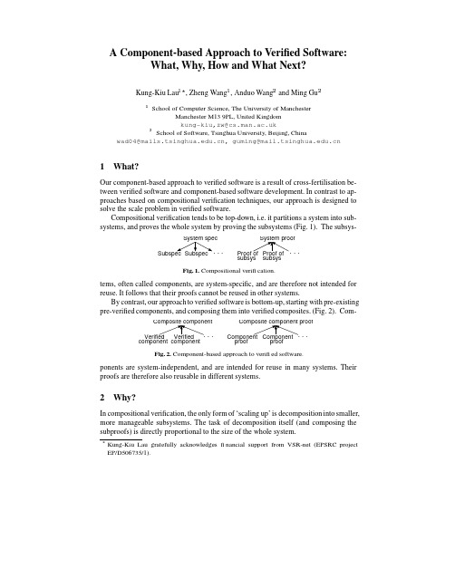
A Component-based Approach to Verified Software:What,Why,How and What Next?Kung-Kiu Lau,Zheng Wang,Anduo Wang and Ming GuSchool of Computer Science,The University of ManchesterManchester M139PL,United Kingdomkung-kiu,zw@School of Software,Tsinghua University,Beijing,Chinawad04@,guming@1What?Our component-based approach to verified software is a result of cross-fertilisation be-tween verified software and component-based software development.In contrast to ap-proaches based on compositional verification techniques,our approach is designed to solve the scale problem in verified software.Compositional verification tends to be top-down,i.e.it partitions a system into sub-systems,and proves the whole system by proving the subsystems(Fig.1).Thesubsys-positional verification.tems,often called components,are system-specific,and are therefore not intended for reuse.It follows that their proofs cannot be reused in other systems.By contrast,our approach to verified software is bottom-up,starting with pre-existingCom-pre-verified components,and composing them into verified composites.(Fig.2).proofproofponent-based approach to verified software.ponents are system-independent,and are intended for reuse in many systems.Their proofs are therefore also reusable in different systems.2Why?In compositional verification,the only form of‘scaling up’is decomposition into smaller, more manageable subsystems.The task of decomposition itself(and composing the subproofs)is directly proportional to the size of the whole system.By contrast,in our component-based approach,scaling up is achieved because each step of composition is independent of the size of the whole system.The total number of composition steps required depends on the size of the whole system as well as the granularity of the components.3How?The pre-requisite for a component-based approach to verified software is that compo-nents and their specification,composition and verification are not only well-defined, but also defined in such a way that verified software can be built in a component-based manner.That is,we need a component model such that it supports this approach.3.1A Component ModelA component model defines what components are,and how they can be composed.We have defined a component model[7]in which we can also reason about components and their composition.The defining characteristics of our components are encapsulation and compositionality,which lead to self-similarity.The defining characteristic of our composition operators is that they are exogenous connectors[8]that provide interfaces to the composites they produce.Self-similarity is what makes our component-based approach possible.It means that our composite components have hierarchical specifications,hierarchical proof obliga-tions,or verification conditions(VCs),and as a result,proof reuse,via sub-VCs,is possible.3.2A Case Study:The Missile Guidance SystemWe have implemented our component model in Spark[2],and using this implemen-tation,we have experimented on an industrial strength case study,a Missile Guidance system[4],which we obtained from Praxis High Integrity Systems.The Missile Guid-ance system is the main control unit for an endo-atmospheric interceptor missile.It consists of a main control unit and input/output.An I/O handler reads data from differ-ent sensors and passes them via a bus to corresponding processing units.These units then pass their results to a navigation unit which produces the output for the system.The implementation in[4]contains246packages including tools and a test harness. In total,it has30,102lines of Spark Ada code including comments and annotations.Using our component model,we have implemented a component-based version of the Missile Guidance system.Its architecture is shown in Fig.3.We reused code from [4]as computation units,and composed them using exogenous connectors.Seq1,Seq1’, Seq2and Seq4are composite components whose interfaces are sequence connectors. Sel2is a composite component whose interface is is a selector connector.Seq3is a sequence connector,Sel1a Selector,Pipe1and Pipe2are pipe connectors and Loop is an iterator.We have proved the system completely,using the Spark proof tools:Examiner,Sim-plifier and Checker;and its proof obligation summary is shown in Fig.4.The summary2Fig.3.A component-based missile guidance system.UndiscgdTotal VCs by type:0000Total Examiner Simp Checker Review False−−−−−−−−−−−−Proved By−−−−−−−−−−−−−−−−−00Assert or Post:Precondition Check Check Statement Runtime check:00Refinement VCs:00Inheritance VCs:−−−−−−−−−−−−−−−−−−−−−−−−−−−−−−−−−−−−End of Semantic Analysis Summary−−−−−−−−−−−−−−−−−−−−−−−−−−−−−−−−−−−−−−−−−−−−−−−−−−−−−−−−−−−−−−−−−−−−−−−−−−−−−−−−−−−−−−−−−−−−−−−−−−−−−−−−−−−−−−−−−−−−−−−−−−−−−−−−−−−−−−−Totals:00% Totals:0%0%9695070137%1494350000350000002818105112860010900193181147929052%10%Fig.4.Proof Obligation Summary of the missile guidance system.is generated automatically by the Spark Proof Obligation Summariser (POGS).It is a summary for the VCs:their total number,types,and numbers discharged by each proof tool.In the proofs of composite components,we succeeded in reusing proofs of sub-components,by virtue of the hierarchical nature of the VCs.We define proof reuse rate for a (composite or atomic)component simply as the ratio of the number of new VCs for the (composition or invocation)connector to the number of VCs in the sub-components (or computation unit).Of course the actual proof effort for each VC is variable,but we believe the ratio of VC numbers does give a first approximation to proof reuse rate.As an illustration of the proof reuse rates for the component-based missile guidance system,we will show the proof reuse rates for part of the system,viz.the composite component Seq4in Fig.3.The subcomponents of Seq4are shown in Fig.5,where ‘Ibm’is the invocation of ‘bm’(Barometer),‘Ias’is the invocation of ‘as’(Airspeed),etc.The proof reuse rate for each sub-component of Seq4is shown in Fig.6.We can see that the bulk of proof efforts goes into proving the computation units of atomic components,but these proofs are only done once and can be reused afterwards.Our component-based approach is able to reuse these proofs effectively,thus reducing the cost of proof efforts of the whole system.3Fig.5.Part of the missile guidance system.Package No. of VCs bm 11Ibm 17as Ias 1119cp 1931Icp ins Iins 15231320Ife fe fz Ifz 1320Ira ra 28Package No. of VCs 28ir Iir 3482%se Ise 21mt Imt 1925dt Idt 1218wh 12Iwh 18cl en Ien 3038352812Icl 21Package No. of VCs Reuse rateReuse rate Reuse rate 352Seq458%61%65%65%65%80%75%76%67%67%57%79%65%98%Fig.6.Proof reuse rates for part of the missile guidance system.More importantly,this experiment confirms that our component-based approach can scale up,because of proof reuse.4What Next?Although the missile guidance system is an industrial strength case study,our exper-iment is only a first step in developing and applying our component-based approach to verified software.Much more remains to be done,and here we outline some future work.4.1Formalisation and Proof of Properties of Component ModelA preliminary formalisation of the semantics of our component model has been done,using first-order logic [7].To prove properties of our component model,we plan to formalise the model in a theory with a proof tool.To investigate this,we plan to use PVS [9].4.2Implementation in Other Languages and ToolsImplementation of our component model in other languages with proof tools,e.g.Spec#[3],JML [6],etc.will be interesting.A comparison with B [1]and its tools will also be illuminating.The objective will be to evaluate whether and how well these models and tools support our model for component-based verified software.44.3Larger ExamplesAlthough the Missile Guidance System is already quite large,it is nowhere near the1 million lines that is the target of the Grand Challenge in Verified Software[5].There-fore,we hope to attempt increasingly larger examples,in order to produce convincing evidence that our model isfit for purpose,as far as the scale problem is concerned. By so doing we can also contribute to the repository of verified code that the grand challenge also seeks to establish.References1.J.R.Abrial.The B-Book:Assigning Programs to Meanings.Cambridge University Press,1996.2.J.Barnes.High Integrity Software:The SPARK Approach to Safety and Security.Addison-Wesley,2003.3.M.Barnett,K.M.Leino,and W.Schulte.The Spec#programming system:An overview.InProc.Int.Workshop on Construction and Analysis of Safe,Secure,and Interoperable Smart Devices,LNCS3362,pages49–69.Springer,2004.4. A.Hilton.High Integrity Hardware-Software Codesign.PhD thesis,The Open University,April2004.5.T.Hoare and J.Misra.Verified software:theories,tools,experiments-vision of a grandchallenge project.In Proceedings of IFIP working conference on Verified Software:theories, tools,experiments,2005.6.The Java Modeling Language(JML)Home Page./˜leavens/JML.html.u,M.Ornaghi,and Z.Wang.A software component model and its preliminaryformalisation.In F.S.de Boer et al.,editor,Proc.4th International Symposium on Formal Methods for Components and Objects,LNCS4111,pages1–21.Springer-Verlag,2006.u,P.Velasco Elizondo,and Z.Wang.Exogenous connectors for software compo-nents.In G.T.Heineman et al.,editor,Proc.8th Int.Symp.on Component-based Software Engineering,LNCS3489,pages90–106.Springer,2005.9./documentation.shtml/.5。
MPLAB Harmony Integrated Software Framework 使用指南说明
RTOS Demonstration Applications Help
Description
This distribution package contains a variety of RTOS-based firmware projects that demonstrate the capabilities of the MPLAB Harmony services and stacks integrated with RTOS running on PIC32 devices. This section describes the hardware requirement and procedures to run these firmware projects on Microchip demonstration and development boards. To learn more about MPLAB Harmony stacks and libraries refer to the related documentation in Volume V: MPLAB Harmony Framework Reference.
Source Code Disclaimers
OPENRTOS The OPENRTOS demonstrations provided in MPLAB Harmony use the OPENRTOS evaluation license, which is meant for demonstration purposes only. Customers desiring development and production on OPENRTOS must procure a suitable license. Please refer to one of the following documents, which are located in the third-party folder of the MPLAB Harmony installation, for information on obtaining an evaluation license for your device: • OpenRTOS Click Thru Eval License PIC32MXxx.pdf • OpenRTOS Click Thru Eval License PIC32MZxx.pdf Micriµm All µC/OS-III demonstrations have added the crt0.S "C" run-time library start-up file to the project. The demonstration sets the linker option "do not link startup code". This is necessary for µC/OS-III to work correctly with PIC32 devices as the general exception vector is located in crt0.S. µC/OS-III overrides this interrupt source (general exception handler) to perform OS-specific functionality. If the user wants to implement their own application using µC/OS-III and a PIC32 device, they must add the crt0.S file to their project and override the general exception interrupt vector. See the current RTOS examples for this implementation. A crt0.S template file can be found in the MPLAB XC32 C/C++ Compiler installation directory: ..\Microchip\xc32\<version>\pic32-libs\libpic32.
Cogent Process-Scale Tangential Flow Filtration Sy

Cogent® Process-Scale Tangential Flow Filtration System A fully-automated, configurable, TFF system suited for manufacturing of biopharmaceuticals and cGMP process-scale applicationsData SheetThe fully automated Cogent® TFF system isdesigned to separate and purify monoclonalantibodies, vaccines, plasma, and therapeuticproteins. It is ideally suited for both pilot andproduction scale applications, therebysupporting rapid scale up from small to largescale operations.Benefiting from our leading bioprocessknowledge and engineering expertise,the Cogent® Process Scale System is theculmination of 25 years of custom systemdesign and incorporates many unique,innovative and intelligent design features.This system has a very low hold-up volumefor maximum volume concentration andoptimal product recovery, thus enhancingprocess performance.Benefits:•M odular standard options allow the unique system configuration that best matches processrequirements while minimizingupfront investment.•F ull process automation eases the consistent production of preclinical and clinical scalequantities of high-value drug products tocGMP standard.•O ptimized design and component integration ofNovAseptic® valves and TFF cassette holders result in a low minimum working volume and ensuremaximum product recovery.•D esigned to maximize TFF performances in fed-batch, concentration, total recycle orsingle pass mode.•C omprehensive services ensure rapidimplementation and optimized performance.2Configure your system according to your process needs…Option 7: Filtrate conductivityMeasurement of a wide range of products (WFI, buffer solutions, protein solutions) or post CIPOption 1: Tank (50, 100, 200L) Jacketed fortemperature regulationOption 10: Retentate pH In-process monitoring of product volumeOption 13: Tank Outlet Level SwitchAllows to stop the feed pump when air reaches this sensor. E.g: In Mini loop concentration mode, detects the end of the step (tank fully empty).Option 12: TankNovAseptic® GMP mixer Ensures producthomogeneity, specially important duringdiafiltration step. Aseptic design, minimized shearingOption 3: Transfer PumpTransfer of product / buffersinto the feed tank fromany other tank. Allowsfed-batch mode, anddiafiltration.Option 8: Filtrate pHpH monitoring duringcleaning and sanitizationproceduresOption 6: Transfer InletManifoldAllows connecting severalinlets to the transfer pumphead (product/WFI/CIP)at the same time, avoidingmany connections /disconnections...and build a consistent user experience3Total Process Controland ConnectivityThe Cogent® Process Scale system is easily controlled via the Common Control Platform® (CCP®) software, a powerful, intuitive and graphical software that provides real-time monitoring and total in-depth control of your TFF process.Using robust PCs, PLCs, and SCADA® technology, it meets the most stringent standards for connectivity,reliability and ease of use.NovAseptic® GMP mixer Embedded NovAseptic® Valves, Mixer and ConnectorsEngineered for optimal performance, reliability, durability and ease of maintenance.The design and development of each component is based on more than 20 years’ experience, focused on aseptic application. This is why we choose to call it ‘‘Aseptic by Design.”Benefits:•C reate process operations using the recipe editor, monitor or control the process in thehome screen, and create reports for the batch using the configurable report generator•D eveloped under GAMP guidelines and FDA 21 CFR Part 11 compliance-ready, including audit trails and electronic signatures for verification •S ensor combinations can be adapted to process requirements allowing the maximum confidence in process monitoring• U tilities to connect all of your separation unit operations to a central network orDCS (e.g. Delta V)• U sed on multiple unit operations CCP® software provides one familiar interface to simplifysoftware management and reduce learning curvesBenefits:•C omply with cGMP Design Qualification criteria for aseptic processing• N ovAseptic® connector ensures no dead legs and maximum product recovery with zero hold up volume.• C omply with the most stringent cleaning and sterilization requirements • M ixer is clean running and is suitable for general mixing, heat transfer and shearsensitive applications.• R educed bioburden• L ower cost of maintenance• D iamond coated mixer bearings ensure long life and optimum performance.• A bility to mix the “last drop”, ensures complete product recovery4Unparalleled UltrafiltrationPlug and PlayThe Pellicon® Process-scale Holder is uniquely designed to reduce the time required to install and removeTFF cassettes at production scale while keeping the flow path unchanged.The holder can be configured with a manual or hydraulic closure. Hydraulic closure can be done with a hand pump or with an automated hydraulic box which allows local or distant control.Biomax® membranePellicon® 3 cassettes with Biomax® membranes are designed for the filtration of therapeutic proteins, albumin, hormones, vaccines and growth factors. These advanced, high-performance cassettes are ideal for today’s processes that require higher operating pressures, temperatures and higher caustic cleaning regimes. Ultracel® membranePellicon® 3 Cassettes with Ultracel® membrane are the device of choice for today’s higher titer therapeutic antibodies as well as the more demanding filtration processes that require low protein fouling. The new D screen is optimized for applications that require higher viscosity and concentration applications.Benefits:•C ompact footprint• T FF cassettes can be installed/removed quickly • E asy to vent and fully drainable, maximizes product recovery • E asy retrofit from manual to hydraulic closure • F low path unchanged, minimizes future re-qualification and validation effort innew process applicationsBenefits:•R obust, void-free membranes for optimum product recovery and performance consistency • A ll thermoplastic design, protective end cap and integrated gasket provides great processconsistency and ease of use• P redictable and fast process scalability from lab to production scale • R obust product design ideally suited to filtration processes with higher operating pressures,temperatures and caustic cleaning regimes• A utomated manufacturing delivers unbeatable performance consistency and reliability• P roven process expertise and technical support to partner with you from development tofull scale manufacturing• O ptimized flow path for higher flux and resolutionseparation capabilityAir Integrity TestIn order to ensure that the cassettes have been installed properly and has not sustained any damage duringstorage and handling, we recommend integrity testing prior to startup and after each post use cleaning.Air Integrity Test accessories consist of a set of air pressure regulators and fittings including assembly procedureto guarantee an easy plug and play solution.Pellicon® 3 Ultrafiltration CassettesThe tangential flow filtration cassette of choice for demanding filtration processes requiring unbeatable performanceconsistency. For use in applications including: monoclonal antibodies, recombinant and non-recombinant proteins,albumin, hormones, vaccines, and growth factors.5Provantage® Bioprocess Consulting ServicesProvantage® Bioprocess Consulting Services leverage our core expertise, products, services and technologyin downstream production to help solve your business problem or challenge. Our commitment to your project outcomes and timelines is managed with our stage gate approach and a dedicated project manager.Application ExpertiseOur Biomanufacturing Sciences Network (BSN) is a global team of over 85 engineers, scientists and technology specialists who provide expertise and peer-to-peer support in process development and manufacturing. We act as an extension of your team, helping you to minimize potential risk and streamline your operations. With over 3,000 client engagements, our toolkit of best practices will ensure your project is delivered on time and within budget.Design and ImplementFrom lab-scale to pilot and manufacturing facility start-up, EMD Millipore is a partner of choice for providing consultative expertise on current best practices to integrate device, hardware and process technology, and process automation. We can provide consultative evaluations for TFF optimization and operating strategies.DevelopWith our 35+ year history manufacturing and implementing TFF technologies, EMD Millipore application specialists develop reproducible,scalable and robust TFF processes that meet your specific requirements and your required scale. OptimizeStarting with a comprehensive technical assessment and characterization of your existing TFF step, EMD Millipore application specialists can recommend and implement TFF enhancements that use best-practice operating conditions and state of the art processes to deliver an optimized and validatable TFF process at your targeted scale, in a timely manner.TransferDuring the lifecycle of a biopharmaceutical, technical transfers occur at various stages: from research to clinical development to commercial manufacturing, and from one manufacturing facility to another.EMD Millipore leverages experienced technical staff, strong project management, and good documentation practices on both sides throughout the course of transfer activities to ensure a robust and successful transfer. TroubleshootEMD Millipore has extensive experience in troubleshoot-ing and investigating manufacturing, method and process development issues. Our experienced team works together collectively with your technical project team to identify the root cause and to develop a robust, acceptable path forward.67Provantage® implementation servicesIn the biopharmaceutical industry, implementing new equipment with respect to Quality rules and guidelines can be challenging. To help you stay ahead in today’s demanding and competitive production environment,SAT and IQ/OQ Operator training CCP® Software Design CCP® Software Training Support for PQQualification package GMP •••Single Molecule cGMP package ••••Full cGMP package•••••our Provantage® Services group provides unparalleled support for implementation of the Cogent® Process Scale System. With a wide range of comprehensive packages to meet your unique manufacturing requirements, resulting in peace of mind and maximum operational flexibility.Provantage® Lab ServicesEstablishing an effective cleaning and sanitization plan for equipment used is a fundamental cGMP requirement necessary to assure the quality and consistency of your drug substance. Effective and consistent membrane cleaning and sanitization after each process cycle is the single most important factor in maintaining system performance.Cleaning and sanitization after every cycle removesresidual foulants and contaminants from the membrane, preventing batch-to-batch carry over, maintaining optimal performance and maximizing the useful life of the filter cassettes.Effectiveness is measured by the ability to control and eliminate microbial contamination, and to remove process foulants to restore membrane performance such that consistent flux and separation are achieved batch after batch.Our Provantage® TFF Cleaning Services can help you develop cleaning and sanitization procedures that assure the safety and purity of your product and maximize the useful life of your TFF cassettes.Benefits:• Q ualify your system with our IQ/OQ service protocols and use our qualified Field Service Engineers with years of product experience to ensure your system functions as specified in cGMP environments • T rain your operators with an interactive,hands-on courses for either system operation, or advanced CCP® software recipe creation training by certified trainers• G et the support of our experiencedBiomanufacturing Engineers during your Process Performance Qualification • M aintain your system with annual preventive maintenance by qualified Field Service Engineers to ensure the lifetime of the system and ultimately reduce your capital expenditures/offices To place an order or receive technical assistanceIn Europe, please call Customer Service: France: 0825 045 645Germany:***********Italy: 848 845 645Spain: 901 516 645 Option 1 Switzerland: 0848 645 645United Kingdom:***********For other countries across Europe, please call: +44 (0) 115 943 0840Or visit: /offices For Technical Service visit:/techserviceMerck Millipore, the M logo, Provantage, Biomax, Ultracel, Pellicon, Common Control Platform, CCP, Cogent, and the M mark are registered trademarks of Merck KGaA, Darmstadt, Germany. NovAseptic is a registered trademark of Millipore AB.Lit. No. DS6445EN00 Rev. A 04/2015 PS-14-10900 Printed in USA.©2015 EMD Millipore Corporation, Billerica, MA 01821 U.S.A. All rights reserved.。
CS200A User Manual
CS200-A,C,D MFC/MFM User’s Manual2 0 10 . 6A NOTE TO OUR CUSTOMERSDear customer,Thank you for purchasing SEVENSTAR CS series Mass Flow Controller and Mass Flow Meter product.This user manual is important when installing and doing maintenance. Please keep it carefully.We strongly recommend that you read this manual thoroughly before you starting to use the product. This user manual introduces the important issues including the proper and safe use of the products.And please notice the words and section with the symbol. Not in accordance with the user manual for the use of property caused by loss or personal injury, SEVENSTAR may not be responsible.If you require any additional information or assistant of Sevenstar CS series Mass Flow Controller and Mass Flow Meter, please feel free to contact your local Sevenstar Sales Agent or Sevenstar Customer Service at:(8610)- 6436 2925.Yours sincerely,SevenstarContentsSECTION 1 INTRODUCTION 3.3 Zero (11)1.1 General..........................................................1 3.4 Soft-Start (12)1.2 Specification.................................................2 3.5 Delay. (12)1.3 Calibration features.....................................3 3.6 Valve Command Mode.. (12)1.3.1 Standard conditions.....................................3 3.7 Valve Type. (12)1.3.2manufacturing environment.........................4 3.8 Multi-Gas and Multi-Flow.. (13)1.3.3precision adjustment....................................4 3.9 Total Flow Accumulator (13)SECTION 2 INSTALLATION 3.10 Alarm (13)2.1 General..........................................................4 3.11 LED. (14)2.2 Unpacking.....................................................4SECTION 4 MAINTENANCE2.3 Mechanical Installation...............................4 4.1 General (14)2.3.1 General........................................................4 4.2 Caution (15)2.3.2 Installation..................................................7 4.2.1 Medium Forbidden. (15)2.3.2.1 1/4VCR Installation.................................7 4.2.2 Seal of the valve (15)2.3.2.2 Swagelok Installation...............................7SECTION 5 TROUBLESHOOTING2.4 Electrical Installation...................................8 5.1 Initial check.. (15)2.4.1 General........................................................8 5.2 Troubleshooting. (15)2.4.2 Connection..................................................9SECTION 6 WARRANTY AND SERVICES2.5 Checking Before Operation.........................10 6.1 Product Warranty. (16)SECTION3 FUNCTIONS 6.2 Services (18)3.1 General..........................................................11APPENDIX I (19)3.2 Control Mode...............................................11APPENDIXⅡ. (21)1of 22Instruction of MFC/MFM1.1 GeneralMass flow controller (MFC) accurately measures and controls mass flow rates, which is widely applied in the fields as: semiconductor and IC fabrication, special materials science, chemical industry, petrolic industry, pharmaceutical industry, environmental protecting and vacuum system researching, etc.. The typical applications include: microelectronic process equipment such as diffusion, oxidation, epitaxy, CVD, plasma etching, sputtering, ion implantation, vacuum deposition equipment, optical fiber melting, micro-reaction equipment, mixing & matching gas system, capillary flow control system, gas chromatograph and other analytical instruments.The CS200-A,C,D MFC/MFM are a latest generation MFC for use in semiconductor applications and demanding industrial uses where its high accuracy and flexibility in interfacing are required.The CS200-A,C,D MFC/MFM incorporate a dual interface, voltage and current as well as RS-485 and DeviceNet digital interfaces. It is possible to operate the instrument completely digitally or it can be operated in analog mode with digital monitoring. CS200-A,C,D series have wide range of power supply(available for ±11 ~ ±16 VDC or +11 ~ +28 VDC).In addition, auto-alarm, change of operating gas and range available through the digital interface. Customer Secondary Development of control and sample software is available through the open protocol.2of 221.2 SpecificationCS200Type CS200A CS200C CS200D Full scale range (N 2)( 0~5,10,20,30,50,100,200,300,500)SCCM( 0~1,2,3,5,10,20,30,50)SLM( 0~2,3,5,10,20,30,50,100,200,300,500)SCCM( 0~1,2,3,5,10,20,30)SLMAccuracy ±1.0% S.P. (≥35% F.S.) ±0.35% F.S. (<35% F.S.)Linearity ±0.5% F.S. Repeatability ±0.2% F.S. Response Time ≤1sec ≤ 0.8 sec (SEMI E17-0600) Valve Rest Position Normally Closed or Normally Open No Valve Normally Closed or Normally Open No ValveNormally Closed or Normally Open NoValve Differential Pressure 0.05~0.35MPa (Flow ≤10slm ) 0.1~0.35MPa (10slm <Flow ≤30slm ) 0.2~0.45MPa (Flow >30slm )<0.02MPa(0.05~0.35) MPa (≤10slm )(0.1~0.35) MPa (>10slm )<0.02MPa(0.05~0.35) MPa (≤10slm )(0.1~0.35) MPa (>10slm )<0.02MPaTemperature Coefficient Zero:≤±0.05% F.S./℃;Span: ≤±0.1% F.S.℃ (Flow ≤30slm ) Span: ≤±0.2% F.S.℃ (Flow>30slm )Zero:≤±0.02% F.S./℃; Span:≤±0.05% F.S./℃Max Pressure 3MPa (435pisg)Zero Drift <0.6%F.S. per year without autozeroLeak integrity 1×10⁻⁹ atm·cc / sec He 1×10⁻¹⁰ atm·cc / sec HeWetted Materials Viton; NeopreneMetal (Stainless Steel V/V, 5Ra)MetalSurface Chemistry—— Cr/Fe ratio >2.0; CrO thickness >20 Angstroms Surface Finish 25Ra 10Ra25RaOperation Temperature (5~45)℃(0~50)℃Input Signal Digital: RS485 or DeviceNet TM Analog:(0~5)VDC or (4~20)mAN/ADigital: RS485 or DeviceNet TMAnalog:(0~5)VDC or (4~20)mAN/ADigital:RS485 or DeviceNet TM Analog:(0~5)VDC or (4~20)mAN/AOutput Signal Digital: RS485 or DeviceNet TMAnalog:(0~5)VDC or (4~20)mA Power Supply ±11 ~ ±16 VDC or +11 ~ +28 VDC(400mA)Electronic Connector 9 pin male sub-D ,15 pin male sub-D ,DeviceNet TM male ,AnalogFittingsVCR1/4” M ;Swagelok Φ6;Swagelok1/4”;Swagelok 3/8´´;Swagelok Φ3, Swagelok1/8” (available to F.S.≤ 5SLM) Swagelok Φ10 (available to F.S.> 30SLM)VCR1/4” M ,Swagelok Φ6,Swagelok1/4”,W-seal ,C-sealWeight 1kg 0.8kg 1.2kg 1kg 1.2kg 1kg3of 22Notes :MFC/MFM is calibrated by N 2 as a standard gas. Units: SCCM (Standard Cubic Centimeter/Min); SLM (Standard Liter/Min) Standard Situation: Tem — 273.15K ( 0 ºC );Air Pressure — 101325 Pa (760mm Hg)F.S. : Full Scale1.3 Calibration FeaturesNormally, the MFC are calibrated close to customer’s requirement ( the requirement should be accorded with the specification). Without customer’s information, the MFC are calibrated under standard conditions.1.3.1 Standard conditionsWithout special conditions specified by the customer, the MFC is calibrated under the following standard conditions:Pressure Outlet: Atmospheric.Normally gas mass flow rate is transferred to gas volume flow rate at standard state. Mass flow rate unit:SCCM ——standard cubic centimeter per minute.SLM ——standard liter per minute.Standard state :Temperature —— 0ºC (273.15K)Pressure —— 101325Pa (760mmHg)At standard state, the gas density will be constant. The multiplication of density and volume flow rate is equal to the mass flow rate. Therefore at the standard state, the volume flow rate can represent mass flow rate.The standard mounting position is horizontal, And other positions such as vertical(inlet up or down),flatwise or customized position are optional. The mounting4of 22position should be specified by the customer to ensure the best accuracy.1.3.2 Manufacturing EnvironmentThe MFC are assembled in a class 100 clean room, calibrated, packaged and controlled in class 1000 environment. The temperature is 22±2℃.1.3.3 Precision AdjustmentEach MFC is accurately controlled for 24 hours after manufacturing on a different calibration bench. The accuracy, the dynamic response, the stability to pressure variations is double checked, only qualified product available for sale.SECTION 2 INSTALLATION2.1 GeneralWARNING: Toxic, corrosive or explosive gases must be handled with extreme care. After installing the MFC, the system should be thoroughly checked to ensure it is leak-free. Purge the MFC with a dry inert gas for one hour before using corrosive gases.IMPORTANT: When installing the MFC, ensure that the arrow on the back of the unit in the same direction as the gas flow.2.2 UnpackingThe CS200-A,C,D MFC/MFM are assembled ,calibrated and clean packaged under clean room conditions. These series products are packaged with two separately sealed plastic bags. The outside is common plastic bag, the inside is clean bag. The outside bag should be removed in the entrance to the clean room. In order to minimize the contamination, the second clean bag should be removed in the clean room when MFC installed in the system.2.3 Mechanical Installation5of 222.3.1 GeneralMost applications will require a positive shutoff valve in line with the MFC. Pressurized gas trapped between the two devices can cause purge effects, and consideration must be given to the sitting of the shutoff valve (upstream or downstream) in relation to the process sequencing. It is recommended that you install an in-line filter upstream to the controller in order to prevent MFC from contamination.CS200-A,C,D should be mounted in the position accord with the requirement in the purchase order. The gas should be clean and dry. The mounting should be free from shock or vibration. The pictures of the product are shown in figure2-1,the dimensions of the product are shown in figure2-2, figure2-3. Different fittings(Swagelok φ6, Swagelok φ3,Swagelok1/4,Swagelok1/8,VCR1/4 M, Swagelok3/8,1.5〞W-seal ,1.5〞C-seal) are optional for customer, The length of the product L are shown in Table 2-1. Donot remove the protective end caps of the fittings until installation.Figure 2-1 CS200-A,C,D MFC/MFMFigure 2-1 Product dimensionsFigure 2-2 Product dimensions Figure 2-3 Product with IGS dimensionsAttention:The height (which is showing in figure 2-2 ) of 132mm are height without electric connectors of cable. It should be added around 50mm more after adding the electric connector.6of 227of 222.3.2 InstallationPlace MFC according to the flow direction.2.3.2.1 1/4VCR ConnectionRefer to figure 2-4 and figure 2-5. Check the gland to gland space, including the gaskets. Remove the plastic gland protector caps. When using loose VCR original style gaskets, inserting the gasket into the female nut. For VCR retainer gaskets, snap the gasket onto the male coupling. Tighten the nuts finger tight. Scribe both nut and body in order to mark the position of the nut. While holding the body with a wrench, tighten the nut: 1/8turn past finger tight for 316L stainless steel and nickel gaskets.Figure 2-4 VCR original style gasketFigure 2-5 VCR retainer gasket2.3.2.2 Two-ferrule (Swagelok) ConnectionRefer to figure 2-6. Check the gland to gland space. Remove the gland protector caps. Insert the tubing to the shoulder inside the fitting, and check that the ferrules are positioned as shown in figure2-6. Tighten the nuts finger tight. Use two spanners, one spanner locking the fitting stable, wrench another one to tighten in 1.25 turns to prove it’s not blow-by afterAttentionWhen installing the fitting, you should manually use spanner to wrench it tighten by 1/2 turn pulling up, 2.4 Electrical Installation2.4.1 GeneralWith simple switching power supply, CS200-A,C,D MFC/MFM are available for ±11 to ±16 VDC (dual-ending) and +11 to +28 VDC (single-ending). Customer can choose as need.Customer can choose 9 pin male Sub-D or 15 pin male sub-D connector. 9 pin male Sub-D connector is the SEMI Standard compatible, only 0-5V analog signal control and output available. 15 pin male sub-D connector, both 4-20mA and 0-5V analog signal control and output available.8of 229of 22 CS200-A,C,D MFC/MFM can communicate with PC via RS485 or DeviceNet.2.4.2 ConnectionsThe 9 pin male Sub-D connector, 15 pin male sub-D connector, RS485 connector ,DeviceNet connector and Analog Signal Interface are shown in figure2-7, figure2-8, figure2-9 , figure 2-10 and figure 2-11.Attention : Although sharing with the same appearance of CS200-A,C,D MFC, the 0~5V Setpoint Input, the 4~20mA Setpoint Input and the valve Over-ride are not available. That means pin1 and pin6 of D-sub 9 and pin1, pin7, pin8 and pin12 of D-sub 15 are not available.Figure 2-7 9 pin male D-sub connector10of 22Figure 2-8 15 pin male D-sub connector Figure 2-9 RS485 connectorFigure 2-10 DeviceNet connector Figure 2-11 Analog Signal InterfaceSevenstar manufactures all standard cables, RS485 adaptor, customized cables and some accessories. For more details, contact Sevenstar or its local agent.2.5 Checking Before Operation11of 22Before operating the MFC the following checks should be completed:2.5.1 Check that tubing is leak free.2.5.2 Check the process sequence and proper function of all other gas components involved.2.5.3 Check the voltage of command signals and power supply to the MFC/MFM.2.5.4 Check that the appropriate type of gas is being supplied at the rated pressure.2.5.5 Allow the MFC to warm up for 20 minutes, and then check the zero level output.2.5.6 Use dry inert gas for test runs.2.5.7 Prior to using the MFC for extremely corrosive gases, purge MFC with a dry inert gas for one hour.SECTION3 FUNCTIONS3.1 GeneralBased on new sensor driver technology, zero balance technology and VCP technology, CS200-A,C,D MFC/MFM presents high performance and reliability. And more digital functions are developed in CS200-A,C,D products.3.2 Control ModeCS200-A,C,D MFC/MFM are available for digital ,0-5V voltage and 4-20mA current control mode and output. When customer chooses one of the three control modes, the others will be screened. The analog output will be available at all times. The flow output of the CS200-A,C,D MFC/MFM will be available through the RS485 interface, even in the analog control mode. The setting of the CS200-A,C,D MFC/MFM can be provided to the MFC through one of three sources, in digital or analog mode.Please refer to “Digital MFC Communication User Manual” for more details.3.3 ZeroThe Zero function can be commanded through the digital interface or zero-button.12of 22Before zero MFC, please make sure that no gas flow through MFC. Then zero MFC by the digital interface or zero-button. The zero-button must be pressed continuously for 0.5 seconds in order to start zero process. The green LED will blink during the zero process. After zero finished, the green LED will be on constantly.3.4 Soft-StartThe CS200-A,C,D MFC/MFM support soft-start function. Soft-start allows customer change the setting of MFC with definite rate. Please refer to “Digital MFC Communication User Manual ” for more details.3.5 DelayDelay is used to postpone the start of flow from zero flow to the received set-point. It is programmed in millisecond but the MFC internally rounds up any value to 100ms. For example, when the delay value is 200, MFC will delay 200ms then receiving the operate command. When the set point is less than the min control rate, the valve will shut off, and when larger than the min control rate, MFC will start after the set delay time.Special default: Values from 1 to 49 ms will be programmed as 100ms. Delay applies to digital and analog set-points.3.6 Valve Command ModeCS200-A,C,D MFC/MFM are available for valve-close or valve-open by input digital signal or analog voltage directly. The Valve Command Mode is used to select one of three ways to interpret the analog signal of Valve Command. Please refer to “Digital MFC Communication User Manual” for more details.3.7 Valve TypeCS200-A,C,D MFC/MFM have two types of valve: Normally open(NO) or Normally closed(NC) . When MFC do not have power supply, the “NO” type valve is open and gas can flow through the MFC; the “NC” type valve is closed and gas can not flow through. Please mention the valve type when you order the MFC.13of 223.8 Multi-Gas and Multi-FlowThe multi-gas and multi-range technology has been developed in the CS200-A,C,D series MFC/MFM. Customer can change gas convert factor, full scale of MFC via digital interface. Full scale of CS200-A,C,D series MFC/MFM can be re-ranged from 30% to 110%F.S. For example, an MFC with 100SCCM full scale , the new full scale can be re-ranged between from 30SCCM to 110SCCM.CS200-A,C,D MFC/MFM support customer offset by the target null value. The target null value is a customer-programmed constant used to offset the flow output independently of all other sensor offset constants, including the zero process. For example, set Target Null Value: -20%F.S ,then when no flow through MFC/MFM ,the reading is -20%F.S ,with gas flow 20%F.S through MFC/MFM ,the reading is 0%F.S 。
第五章文献的类型及识别

一次文献
以作者本人取得的成果为依据而创作的论 文、报告等经公开发表或出版的各种文献, 习惯上称做原始文献。如:期刊论文、学术 论文、学位论文、科技报告、会议论文、专 利说明书、技术标准等。一次文献是人们学 习参考的最基本的文献类型,也是最主要的 文献情报源。是产生二、三次文献的基础, 是文献检索和利用的主要对象。其主要特点 是内容新颖丰富,叙述具体详尽,参考价值 大,但数量庞大、分散。
例: Some approaches to the design of high integrity software.(1)D.J.Marttin, R.B.Smith(Combat Controls Div.GEC Avionics Ltd.Rochester,UK).(2)Report AGARD-TR 2584(3)July 2001(4) (1)篇名 (2)著者和著者单位 (3)报告号 (4)出版年月
黑色文献
包括两个方面,一是人们为破译和未便是 其中信息的文献,如考古发现的古老文字未 经分析厘定的文献;二是处于保密状态和不 愿公布其内容的文献,如未解密的政府文件、 内部档案、个人日记、私人信件等。这类文 献除作者及特定人员外,一般社会成员极难 纸介型文献 缩微型文献 声像型文献 电子型文献
二次文献
报道和查找一次文献的检索工具书、书刊。 如各种目录、题录、简介、文摘和索引等。 二次文献是按照特定目的对一定范围或学科 领域的一次文献机型鉴别、筛选、分析、归 纳和加工整理重组等,使之有序化后出版的。 它以不同的深度揭示一次文献,其主要功能 是检索、通报、控制一次文献,帮助人们在 较少时间内获得较多的文献信息。二次文献 具有汇集性、工具性、综合性、交流性等特 点。
第五章 文献的类型及识别
5.1 文献的类型 5.2 不同出版类型文献的著录特征及其识别
海尔曼高性能点位调节器系列说明书
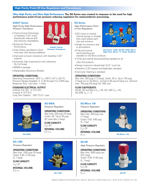
•Thermo-Fused Technology to Hastelloy C-22®which dramatically reduces driftand improves repeatability. •Enhanced ThermalPerformance. •Case Stress cancellation which minimizes shift during installation.•Improved corrosion resistance with Hastelloy C-22®material.•Extremely high overpressure ratio tolerances (3x Full Scale). •NEMA 4 package.•Replaceable Electronics Module.SQ SeriesHigh Performance Point-of-Use Regulators SQ Micro 130Pressure Regulator SQ 60SAPressure Regulator •SQ’s have no wetted internal springs or threads that could release parti-cles and moisture.•Single low pressure seal to atmosphere.•5 Ra and internalelectropolishing arestandard on SQ Micro products.•10 Ra and internal electropolishing standard on all other SQ products.•Design maximum inboard leak 2x10⁻¹⁰scc/s He.•Hastelloy C-22®poppet and diaphragm standard.•Hurricane Cleaning is standard.SQ Series: 140E, SQ HP , 420E, Micro High Flow, Micro “A ”Style, 60,MicroOPERATING CONDITIONS: Max Inlet: 250 psig (70 barg) Outlet: 28” Hg to 30 psig (67 mbar Abs .2 barg)FLOW CAPACITY:C v =.20INTERNAL VOLUME:5.2 c.c.OPERATING CONDITIONS Max Inlet: 250 psig max (17 barg)Outlet: 0-30, 0-60 psig (2, 7 bar)FLOW CAPACITY C v =.20INTERNAL VOLUME 5 c.c.OPERATING CONDITIONS:Max Inlet: 250 psig (17.2 barg), Outlet: 20 in. Hg to 100 psig(7 barg) not on SQ Micro - limited to 60 psig (4 barg) out, Optional Inlet: 750 psig (52 barg) SQ 140E onlyFLOW COEFFICIENTS:SQ 60, HP and Micro C v =.05, SQ 140E C v =.25,SQ 420E C v = 1.5Ultra High Purity and Ultra High Performance The SQ Series was created in response to the need for high performance point-of-use pressure reducing regulators for semiconductor processing.SQ Micro 130SQ 60SASQ HPHigh Pressure Regulator SQ 130EPressure RegulatorOPERATING CONDITIONS Max Inlet: 1000 psig (70 barg) Outlet: 0-30, 0-100 psig (2, 7 barg)FLOW CAPACITY C v =.22INTERNAL VOLUME 5.2 c.c.OPERATING CONDITIONS Max Inlet: 3500 psig max (241 barg)Outlet: 0-30, 0-100 psig (2, 7 barg)FLOW CAPACITY C v =.05INTERNAL VOLUME 5 c.c.SQ HPSQ 130EEXACT SeriesPressure Transducer EXACT SeriesHigh Purity High Performance Pressure TransducerOPERATING CONDITIONS:Operating Temperature: -20ºC to +105ºC (-4°F to 221°F),Pressure Ranges Available: 0 to 30 through 0 to 3,000 psig,Response Time: Less than 1 mSec STANDARD ELECTRICAL OUTPUT: 4-20mA, 0-5 VDC, .5-10.5 VDC Linearity 0 10-8 F .S.O.Long Term Stability - 250˚ F .S.O 1 yearVeriflo’s line of high purity valves provide the ultimate in performance for a unlimited variety of applications.955 SeriesHigh Flow Diaphragm Valves 944 SeriesDiaphragm ValvesOPERATING CONDITIONS:FLOW CAPACITY LEAKAGE:944 (L, LL, S, I, M): Vacuum to 3500 psig (241 barg)944 LL: C v =.18944 L or M: C v =.18 Inboard 2x10⁻¹⁰scc/s He 944 AOP LP: Vacuum to 125 psig (8.6 barg)944 S or G: C v =.25944 I: C v =.25944 AOP HP: Vacuum to 3500 psig (241 barg)944 AOP LP: C v =.25944 AOP HP: C v =.25INTERNAL VOLUME:944G: Vacuum to 125 psig (241 barg)3.36 c.c944 LL, 944 I,944 S, 944 L955 AOP NC, 955 I,955 AOP LP NO, 944G955 YOPERATING CONDITIONS:955 AOP LP: Vacuum to 125 psig (8.6 barg)955 S, G or I: Vacuum to 250 psig (17.2 barg)FLOW CAPACITY: C v =.55 (except 955L = .32)LEAKAGE: Inboard 2x10⁻¹⁰scc/s He INTERNAL VOLUME: 3.29 c.c.955 Y SeriesHigh Flow Manifold Valves OPERATING CONDITIONS: Vacuum to 125 psig (8.6 barg)LEAKAGE: Inboard: 2x10⁻¹⁰scc/s HeFLOW CAPACITY: Process Valve C v =.43, Purge Valve C v =.35944 AOP LP NO, 944 AOP HP , 944 AOP LP NC,•Fully field serviceable seat without special tools.•Available in a variety of multi-port configurations and connections - see Valve Selection Guide.•Internally threadless and springless.•Fully functional under all vacuum conditions.•5 Ra and internal electropolishing is standard.•Available in a variety of multi-port configurations and connections - see Valve Selection Guide.•5 Ra and internal electropolishing is standard.•Ideal for valve manifold boxes (vmb) and high flow OEM gas lines.•Large C v ideal for low vapor pressure gases.• Available with a variety of flow paths.OPERATING CONDITIONS:Vacuum to 125 psig (8.6 barg)LEAKAGE:Inboard: 2x10⁻¹⁰scc/s He.FLOW CAPACITY:Process Valve C v =.25, Purge Valve C v =.17Series SPR 860Servo Operated Pressure Regulator The Servo-Operated Series Regulators: Servo driven regulators are self adjusting and can achieve flows of up to2500 lpm and with negligible droop (1-2 psig).SQ ServoHigh Flow High Purity Servo Regulator Left: SPR 860 Right: SQ ServoOPERATING CONDITIONS:Maximum supply pressure: 750 psig (52 barg)LEAKAGE:Inboard: 2x10⁻¹⁰scc/s He.OPERATING CONDITIONS:LEAKAGE:Inlet: SPR 860 V: 500 psig (35 barg)Inboard: 2x10⁻⁹scc/s He.SPR 860 K: 200 psig (14 barg)Outlet: 1-30, 2-100 psig (2, 7 barg)945High Purity Valves945945YHigh Purity Valves 945YFLOW CAPACITY:945 L: C v = .18945 S, I, AOP , 945Y: C v = .25935 Series1/2” Facility ValveOPERATING CONDITIONS: Vacuum to 300 psig (20.7 barg) FLOW CAPACITY:C v = 2.8 (orifice size =0.5 in)LEAKAGE:Inboard 2x10⁻¹⁰scc/s He INTERNAL VOLUME: 16.2 c.c.Back: 935 Y , 935 T Front: 935, 935 / 917 L917917 SeriesHigh Purity Diaphragm Valve •Low internal volume.•Fully functional under all vacuum conditions.•Air operated valves are fully functional from a vacuum to 250 psig. •Fixed male gland-to-gland dimensions available (2.3").• 100% helium leak tested.• 1/8” connection option.•Internally threadless and springless.•Fully functional from vacuum to 300 psig.•Available up to 1” Tube Stubs.• 935/917 has a valve isolated purge or test port.•Ideal for valve manifold boxes (vmb) and high flow OEM gas lines •Available with a variety of flow path options•Low internal volume, 1.27 c.c.•Machined on tube stubs or fixed male face seal available.•Field serviceable.•5 Ra and internal electropolishing is standard.•Hurricane cleaning is standard.•For extremely high flows with a low pressure differential.•Does not require an external source to operate nor a continuous bleed to atmosphere.•Requires an external. source to operate •No internal springs •Facilities regulatorOPERATING CONDITIONS:917 (L, M, I and S): Vacuum to 3000 psig (207 barg)917 AOP: Vacuum to 250 psig (17.2 barg)Vacuum to 500 psig (34.5 barg)(using 955 Actuator)FLOW CAPACITY:917 L: C v = .15917 AOP:C v = .17917 I: C v = .17917 S: C v = .17LEAKAGE:Inboard 2x10⁻¹⁰scc/s He.959 TDR735 TDRTwo-Stage Tied Diaphragm Regulator 959 TDRTied Diaphragm RegulatorOPERATING CONDITIONS:Inlet: 3500 psig (241 barg)Outlet: 0-30, 0-100 psig (2, 7 barg)FLOW CAPACITY:C v =.04INTERNAL VOLUME: 7.3 c.c.OPERATING CONDITIONS:Inlet:3500 psig(241 barg) Outlet: 0-30, 0-100 psig (2, 7 barg)FLOW CAPACITY:C v =.04INTERNAL VOLUME:4.0 c.c.OPERATING CONDITIONS:Inlet: 3500 psig(241 barg) maximumOutlet: 0-20 in Hg to 30 psig (0-2 barg)NPR 959Negative Pressure Regulator QR SeriesNon-Tied Diaphragm Regulator OPERATING CONDITIONS:Inlet:4000 psig(276 barg) Outlet: 1-10,1-30, 2-60, 2-100,3-250(.7,2,4,7 ,17 barg),FLOW CAPACITY: (Typical) C v = .09(Gas C v Per ANSI/ISA S 75.02 1988)INTERNAL VOLUME:4.0 cc or 6.19 cc with fittingsQR SeriesNPR 400Negative Pressure Regulator OPERATING CONDITIONSInlet: 150 psig (10 barg)Outlet: 2 psig (.1 barg)•No high pressure seals to atmosphere.•Metal-to-metal diaphragm seal assures high leak integrity.•No high pressure seals to atmosphere.•Metal-to-metal diaphragm seal assures high leak integrity.•Adjustment range spring may be replaced without breaking the diaphragm seal to the body and exposing the wetted area to contamination.•Suitable for corrosive and non-corrosive gases.•Tall spring for excellent sensitivity.NPR 400NPR 959•Designed to minimize supply pressure effect.•Adjustment range spring may be replaced without breaking the diaphragm seal to the body and exposing the wetted area to contamination.•Metal-to-metal diaphragm-to-body seal assures high leak integrity•Capable of operating at negative pressures of up to 20 in. Hg.•Threadless.735 TDRIR 400Pressure Regulator HPR 800High Pressure Regulator DIR 600Two-Stage Regulator Brass IR 400HFR 900OPERATING CONDITIONS:Inlet: 4000 psig (275 barg)Outlet: 3-30, 2-100, 5-300, 10-500 psig(2, 7, 21, 34 barg)BODY:Brass Bar stock FLOW CAPACITY: C v =.02OPERATING CONDITIONS Inlet: 5000 psig (344 barg) at 70°F (21°C)Outlet: 10-800, 20-1500, 50-2500 psig, (55, 103, 172 barg)FLOW CAPACITY:C v =.02LEAKAGE:Inboard: 2x10⁻⁹scc/s HeHFR 900High Flow Pressure Regulator DSG 750Two-Stage Regulator Stainless SteelOPERATING CONDITIONS:Inlet: 500 psig (35 barg)Inlet: 200 psig (14 barg)Outlet: 1-30, 2-75, 5-150 psig (2, 5, 10 barg)HIR 2000High Purity Regulator OPERATING CONDITIONS:Inlet: 3500 psig (241 barg)Outlet:0-30 psig (0-2 barg),0-60 psig (0-4 barg),0-100 psig (0-7 barg)FLOW CAPACITY: C v =0.02LEAKAGE:Inboard: 1x10⁻⁹scc/s He INTERNAL VOLUME:13.8 c.c.OPERATING CONDITIONS: FLOW CAPACITY: C v =.02Inlet: 3000 psig (207 barg)Outlet: 1-15, 2-75, 5-150 psig (1, 5, 10 barg)LEAKAGE: Inboard: 2x10⁻⁹scc/s HeHIR 100Pressure RegulatorOPERATING CONDITIONS: Inlet: 3000 psig (207 barg)Outlet: 1-15, 1-30, 2-75, 5-150 psig (1, 2, 5, 10 barg)FLOW CAPACITY: C v =.13LEAKAGE:Inboard: 2x10⁻⁹scc/s He INTERNAL VOLUME:9.30 c.c.FLOW CAPACITY:LEAKAGE:C v =.85Inboard: 2x10⁻⁹scc/s HeINTERNAL VOLUME: 38 c.c.HIR 100HPR 800DIR 600HIR 2000DSG 750OPERATING CONDITIONS: Inlet:3000 psig (207 barg)Outlet:1-15, 2-75, 5-150 psig (1, 5, 10 barg)FLOW CAPACITY:C v =.13LEAKAGE:Inboard: 2x10⁻⁹scc/s He•High flow, mid purity regulator.•Large diaphragm area for minimal pressure drop.•Suitable for corrosive service and non-corrosive gases.•Low actuating torque •Diaphragm sensing regulator •Designed to reduce supply pressure effect •Large diaphragm area provides excellent flow curves.•Minimizes supply pressure effect •Large diaphragm area provides excellent flow curves for corrosive and non-corrosive gases •Fully field service availablefpo - High Res. Scan on file at LCP。
MagNAPure Compact 核苷酸纯化系统说明书

MagNA Pure Compact System Versatile Nucleic Acid Purification__________________________MagNA Pure Compact Instrument__________________4_____________________________MagNA Pure Compact Software____________________7_____________________________MagNA Pure Compact Reagent Kits________________8MagNA Pure Compact Nucleic Acid Isolation Kit IMagNA Pure Compact Nucleic Acid Isolation Kit I—Large VolumeMagNA Pure Compact RNA Isolation Kit_____________________________Additional Products______________________________12 _____________________________Ordering Information_____________________________132|The MagNA Pure Compact System is the automated benchtop solution for nucleic acid purification.With its small instrument size, extensive integrated features,such as conveniently prefilled reagents and disposables,and a sample throughput of one to eight samples per run,the instrument meets the demanding nucleic acid isolation needs of research laboratories with low to medium sample throughput.For general laboratory useThe MagNA Pure Compact SystemVersatile Nucleic Acid Purification—Smart.Small.Simple.Conserve valuable laboratory spacewith the small footprint.Obtain high-quality nucleic acidsfrom diverse sample types with provenreagent chemistry.Incorporate a variety of protocolsusing different specimen and elution volumesfor a broad range of sample materials.Save time through easy setup with prefilledreagents and disposables.Eliminate contamination with prefilledreagents and disposables,an integratedHEPA filter,and synchronized stage move-ment.Ensure isolation success with a sensorfor tip loss,clot,and cartridge detection.Track sample identification with thesupplied bar-code scanner.Simplify documentation via hostconnectivity.Navigate easily with the intuitive softwareand touch-screen monitor.᭡Figure1:The MagNA Pure Compact Instrument|34|The MagNA Pure Compact Instrument Automated benchtop nucleic acid purification ᭡Figure 2:Schematic of nucleic acid purification using the MagNA Pure Compact Instrument.Sample Cell disruption Nucleic acid Magnetic Removal of Magnetic Nucleic acid material and protein binding to the separation of cellular debris separation of elution at high digestion by surface of Magnetic the nucleic by extensive the nucleic temperatures the addition of Glass Particles acid-bead washing steps acid-bead during the removal Lysis Buffer and (DNA is removed complex complex of the Magnetic Proteinase K by DNase digestion)Glass Particles Save space in your lab —small instrument footprint design Benefit from a benchtop instrument with a small foot-print (540mm W x 610mm D [21.3in W x 24.0in D]).The MagNA Pure Compact Instrument fits on all conventional laboratory countertops.Even in labs with limited space,you can integrate automated nucleic acid isolation of up to eight samples right at your bench.Purification options as diverse as your nucleic acid research Different applications and sample types require different nucleic acid purification methods.The MagNA Pure Compact System incorporates a variety of experimental protocols using different specimen (100–1000µl)and elution (50–200µl)volumes from a wide variety of sample materials (e.g.,blood,tissue,or cultured cells).Proven purification technology The MagNA Pure Compact Instrument uses a proven magnetic-bead technology (Figure 2)successfully used throughout the world in many publications.᭡Figure3:Reagent Cartridge and accessories.Single-sample reagents and disposables are prefilled sealed Reagent Cartridges. An individually-packaged Tip Tray and disposable piercing tool for opening cartridge seals are also provided.InstrumentConvenience and automation—everything ready to goPurify high quality nucleic acids with minimum effort.Save time using MagNA Pure Compact Instrumentintegration from the beginning to the end.Experimental setup is easy and requires a minimumhandling time.Intuitive,software-guided setup,prefilled sealed Reagent Cartridges and disposables,guarantee excellent performance.Ready-to-useprotocols for all available applications are storedonboard.The MagNA Pure Compact nucleic acid purificationkits contain all reagents and disposables neededfor32nucleic acid isolation reactions.The disposableconfiguration eliminates reagent pipetting,single tiploading,and piercing tool cleaning,thus minimizingwaste(Figure3).|56|Intuitive design ensures sample safetyThe MagNA Pure Compact System has a variety ofintuitive features for eliminating cross-contaminationassuring maximum of safety throughout thepurification workflow.Quickly and easily track samplesand reagents with the integrated barcode scannerand prelabeled Reagent Cartridges and Elution Tubes(Figure4).Protect each sample with the instrument’ssynchronized stage movement,integrated HEPA filter,UV decontamination,and prefilled and sealed reagentsand disposables.Ensure isolation success with theinstrument’s sensor for tip loss,clot,and cartridgedetection(Figure5).Isolation protocols for blood andplasma automate pipetting of an internal control,to prevent its degradation by extracellular nucleases.᭡Figure5:Pipetting station and nozzle head.During theisolation process,a stepper motor moves the cartridge stageholding the Reagent Cartridges and the Sample and Elution tubes.An eight-nozzle pipetting head processes the samples,frompiercing the sealing foil on the cartridge to the final nucleic acidelution.A pressure sensor integrated into the nozzle head detectsaccidental clotting or tip loss during sampleprocessing.᭡Figure4:Barcode scanning of an Elution Tube in the ElutionTube Rack.In addition to the Reagent Cartridge,each Elution Tubeis labeled with a unique barcode that is unambiguously identifiedand tracked throughout the remaining processingsteps.|7MagNA Pure Compact SoftwareIntegrated and intuitive,at your fingertipsSoftwareNavigate with touchscreen-driven softwareThe MagNA Pure Compact Software is controlled byan integrated computer,and navigated by a touchscreenmonitor (Figure 6),guiding the user through the setupand run (Figure 8).Preinstalled isolation protocols areselected by scanning the barcode on the kit’s ReagentCartridges (Figure 7).State-of-the-art user managementand host connectivity (ASTM/RS232)complete thecomprehensive features of the streamlined software forautomated nucleic acid purification.᭡Figure 6:T ouchscreen monitor.The MagNA Pure CompactInstrument features a touchscreen monitor,integrated computer,and a barcode scanner for sample tracking.All available isolationprotocols are preinstalled and can be selected by scanning theReagent Cartridges’barcodes.The user is guided through setupand run.State-of-the-art user management and host connectivity(ASTM/RS232)compatibility complete the comprehensive features.᭡Figure 7:Kit information in the Reagent Cartridge barcode.Each kit’s Reagent Cartridges are labeled with a barcode with information about kit name,lot,and expiration date.Based on this information,the MagNA Pure Compact software selects appropriate protocols and notifies the user if the kit is expired.All barcode data are automatically saved by the system.᭡Figure 8:Sample Ordering Screen.Pull-down menus allow the user to select appropriate parameters for sample and elution volume and sample material.Protocol selection may also be done by barcode scanning of the kit’s ReagentCartridges.8|᭡Figure 10:PCR detection of Her2neu sequences using the LightCycler ®Carousel-Based System.DNA was isolated from human whole blood research samples stabilized with different anticoagulants using the MagNA Pure Compact System.The endogenous sequence Her2neu was detected using the LightCycler ®Carousel-Based Real-Time PCR System.Eluate stability at different conditions was demonstrated.No significant deviation in LightCycler ®crossing points is observed using either anticoagulants or different storage conditions.᭡Figure 9:PCR detection of different human targets in research samples using the LightCycler ®Carousel-Based System.DNA eluates from whole blood samples were generated with the MagNA Pure Compact System,split immediately after elution,and stored at different conditions.PCR was performed using two parameters which detect internal sequences (Factor V and Her2neu),and two parameters which detect spiked sequences using the internal control function of the MagNA Pure Compact Instrument (Epstein-Barr Virus and Parvovirus B19).No significant influence of different storage conditions on amplification performance was observed.MagNA Pure Compact Reagent kit selection guide*e.g.,BAL (bronchoalveolar lavage),sputum,cerebrospinal fluid,urine,swabs.Stability 2520151050L C C r o s s i n g P o i n t EDTA–Her2neu Citrate–Her2neu Heparin–Her2neu 403020100L C C r o s s i n g P o i n t Factor V Her2neu EBV ParvoB19after elution 4h/RT 20h/RT 20h/4ºC 20h/-20ºC after elution 4h/RT 20h/RT 20h/4ºC 20h/-20ºC|9Reagent Kits MagNA Pure Compact Reagent KitsKit specifications and resultsScalabilityReproducibility ᭣Figure 11:Scalability of DNA yield.Different amounts ofK-562tissue culture cells were used to isolate DNA using theMagNA Pure Compact Nucleic Acid Isolation Kit I.In the rangefrom 1x 10⁵to 1x 10⁶cells,DNA yield (determined by ODmeasurement)perfectly matches the number of cells that were processed by the MagNA Pure Compact Instrument.252015105D N A yiel d (µg )Cell number (x 105)024681012Integrity1234M 56789101112M 13141516᭡Figure 12:Integrity of DNA isolated from different volumes of EDTA-stabilized whole blood using the MagNA Pure Compact Nucleic Acid Isolation Kit nes 1-4:100µl sample volume/100µl elution volume;Lanes 5-8:200µl sample volume/100µl elution volume;Lanes 9-12:300µl sample volume/100µl elution volume;Lanes 13-16:400µl sample volume/100µl elution volume;M:Roche DNA Molecular Weight Marker III (Cat.No.10528552001).᭡Figure 13:Reproducibility in analysis using the LightCycler ®Carousel-Based System.Twenty-four plasma samples were spiked with Parvovirus B19(105copies/ml).Nucleic acids were isolated from 400µl of the spiked plasma samples using two different MagNA Pure Compact Instruments and the MagNA Pure Compact Nucleic Acid Isolation Kit I.Samples were eluted in 50µl elution buffer and the eluates were analyzed for the presence of Parvovirus DNA with the LightCycler ®Carousel-Based System.The results show the excellent reproducibility of the isolationprocedure.Integrity Sensitivity 10|MagNA Pure Compact Reagent Kits Kit specifications and results ᭡Figure 14:Integrity of DNA isolated from different volumes of EDTA-stabilized whole blood with the MagNA Pure Compact Nucleic Acid Isolation Kit I –Large Volume.DNA was isolated from 500and 1000µl of EDTA-stabilized whole blood,each in an elution volume of 200µl.Sixteen microliters of each sample eluate was analyzed on a 0.8%agarose gel and compared to Molecular Weight Marker III (Roche Applied Science Cat.No.10528552001).᭡Figure 15:Citrated plasma was spiked with a dilution series of human Parvovirus B19in the range of 102to 107copies per ml of plasma (this virus is of significance in the quality control of the plasma processing industry).Nucleic acids were isolated from 1000µl of spiked plasma using the MagNA Pure Compact Nucleic Acid Isolation Kit I –Large Volume,with an elution volume of 100µl.Five microliters of eluate was used for PCR analysis with the LightCycler ®Carousel-Based System (corresponding to 5copies to 5x 10⁶copies per PCR,assuming a 100%recovery).As little as 500copies/ml (=5copies per PCR)are detected,showing excellent sensitivity and linearity.500µl sample 1000µl sample M 12345678M 9101112131415163836343230282624222018102103104105106107Virus concentration [1ml sample]C r o s s i n g P o i n tIntegrityReproducibility|11Reagent Kits᭣Figure 18:MagNA Pure Compact RNA Isolation Kit,RNAintegrity and scalability.Total RNA was isolated from 10,5,and2.5mg of mouse liver in triplicate,each in an elution volume of100µl.The integrity of the RNA was shown by subjecting 2.5µlof each eluate to agarose gel electrophoresis and comparisonto Molecular Weight Marker VI (Roche Applied Science Cat.No.11062590001).All samples show intact 28S and 18S rRNA bands.The resulting band intensities confirm the excellent scalability ofthe isolation procedure.᭡Figure 16:LightCycler ®RT-PCR analysis of RNA isolated with the MagNA Pure Compact RNA Isolation Kit.RNA was isolated from 200µl whole blood in eight replicates,each in an elution volume of 50µl.Five microliters of each sample was analyzed by RT-PCR on the LightCycler ®Carousel-Based System using Cyclophilin A-specific primers and HybProbe probes.The results show the excellent reproducibility of the isolation procedure.No signs of PCR inhibition were observed.᭡Figure 17:Affymetrix GeneChip Analysis of RNA from two independent isolations with the MagNA Pure Compact RNA Isolation Kit.RNA was isolated from 1x 10⁶K-562cells in two independent isolation runs and analyzed on an Affymetrix GeneChip HG-U133Plus 2.0.The log intensity scatter plot shows highly reproducible results with an r²value of 0.995.28S rRNA 18S rRNA12|Use the MagNA LyserInstrument to easilyhomogenize your samples.This unique and auto-mated instrument is theideal companion to theMagNA Pure CompactInstrument.Homogenizeup to16samples in justa few minutes and then proceed to your automatednucleic acid purification.The MagNA Lyser Instrument—Simplify labor-intensive sample preparation᭡Figure20:MagNA LyserGreen Beads Add your sampleand lysis buffer tothe MagNA LyserGreen Beads.Homogenize with theMagNA Lyser Instrument.Centrifuge topellet the debris.Use the super-natant to preparenucleic acids orproteins.MagNA Lyser InstrumentSpecifications Cat.No.0335*******(230Volt)Cat.No.0335*******(110Volt)Dimensions W305mm x D381mm x H280mmW12in x D15in x H11inWeight19.8kg(44lbs)Capacity Rotor with1–16positionsRotor Quick-release rotorPower Source AC110to240VPower Usage Max.1kWAdd the following Roche instruments to yourgenomics workflow to meet your demanding researchneeds:MagNA Lyser Instrument—Automated tissuehomogenizationMagNA Pure LC2.0System–Nucleic acid isolationand reaction setup in a32-well formatMagNA Pure96System–Nucleic acid purificationwith real high throughput,up to96samples in lessthan one hourFor additional information,visit᭡Figure19:MagNA Lyser WorkflowThe MagNA Pure Compact SystemThe integrated solution for genomicresearchOrdering InformationMagNA Pure Compact0373********instrument including Automated nucleic acid isolationInstrument internal PC with touch-for a broad range of applicationsscreen monitor andbar-code scannerMagNA Pure Compact0373********kit(32isolations)•Genomic DNA from mammalianNucleic Acid Isolation Kit I including all required whole blood or cultured cellsplastic disposables•Viral nucleic acids fromplasma or serum•Sample volume range100µl–400µlMagNA Pure Compact0373********kit(32isolations)•Genomic DNA from mammalianNucleic Acid Isolation Kit I—including all required whole blood or cultured cellsLarge Volume plastic disposables•Viral nucleic acids fromplasma or serum•Sample volume range500µl–1000µlMagNA Pure Compact048029930011kit(32isolations)•RNA from mammalianRNA Isolation Kit including all required tissue,blood,cultured cells,plastic disposables and blood cells•Sample amount up to10mgMagNA Pure Bacteria0465918000120ml•DNA from bacteria in manyLysis Buffer different sample types,such asurine,BAL(bronchoalveolarlavage),sputum,CSF,swabs,orbacterial culturesAdditional Products for the MagNA Pure Compact SystemMagNA Pure Compact Tip Tray Kit0375316600110tip traysMagNA Pure Compact Waste T ank0378********waste tankMagNA Pure Compact Tube Rack0378********tube rackMagNA Pure Compact Elution Tube Rack0378********tube rackMagNA Pure Compact Drip Tray0434********drip trayMagNA Pure Compact Cartridge Rack0378********cartridge rackMagNA Pure Compact Drop Catcher0378********drop catcher|13Additional ProductsMagNA Lyser Instrument0335********instrument(230Volt)plus2rotors,1rotor stand,and1cooling block0335********instrument(110Volt)plus2rotors,1rotor stand,and1cooling block MagNA Lyser Green Beads03358941001100tubes,prefilled with ceramic beadsMagNA Pure LC2.0Instrument0519********instrument plus related products,data station andtouchscreen integratedMagNA Pure96Instrument0519********instrument,control unit,software,and accessoriesLC Carousel Centrifuge2.0037095820011instrument(230Volt)0370********instrument(110Volt)LightCycler®2.0Instrument0353********instrument plus related products and data station(desktop or notebook version)LightCycler®480Instrument ll050152780011instrument(96well)050152430011instrument(384well)Roche Applied ScienceService and SupportAt Roche Applied Science we are committed to providing innovative,high-quality instruments and reagents combined with excellent customer service offering powerful tools to address the evolving needs of life science researchers worldwide.Whether you need expert technical support,online access to comprehensive product information, convenient on-site product supply service and online ordering,or outstanding customer service to ensure accurate and timely product delivery,we provide a wealth of resources to help you achieve your research goals.For more information,visit to explore our products and services or to find a local representative.14|TrademarksHYBPROBES,LIGHTCYCLER,MAGNA L YSER and MAGNA PUREare trademarks of Roche.All other product names and trademarks are the property oftheir respective owners.NOTICE:This product may be subject to certain use restrictions.Before using this product please refer to the Online TechnicalSupport page()and searchunder the product number or the product name,whetherthis product is subject to a license disclaimer containing userestrictions.NOTICE TO PURCHASER:This is a product licensed underpatents owned by Qiagen.For general laboratory use|15Published byRoche Diagnostics GmbH Sandhofer Straße11668305MannheimGermany©2012Roche Diagnostics.All rights reserved. ***********ᕄ0212。
工贸一体会计流程

工贸一体会计流程The accounting process in the integrated industrial and commercial sector may present various challenges to maintain accuracy and efficiency. 工贸一体化行业的会计流程可能会在保持准确和高效方面遇到各种挑战。
It is crucial for businesses to establish a well-organized accounting system to ensure compliance with regulations, track financial transactions, and provide a clear understanding of the company's financial status. 企业建立一个组织有序的会计系统是至关重要的,以确保遵守法规,跟踪财务交易,并清晰了解公司的财务状况。
One of the key challenges in the accounting process for integrated industrial and commercial businesses is the complexity of financial transactions. 工贸一体化企业的会计流程面临的一个关键挑战是财务交易的复杂性。
With multiple departments and diverse business operations, there can be a high volume of transactions that need to be accurately recorded and classified. 随着多个部门和多样化的业务运营,可能会有大量需要准确记录和分类的交易。
GE供应商、承包商和顾问廉正指南说明书

A Message from GEThe General Electric Company (“GE”) is committed to unyielding Integrity and high standards of business conduct in everything we do, especially in our dealings with GE suppliers, contractors and consultants (collectively “Suppliers”). For well over a cent ury, GE people have created an asset of incalculable value: the company’s worldwide reputation for integrity and high standards of business conduct. That reputa tion, built by so many people over so many years, depends on upholding it in each business transaction we make.GE bases its Supplier relationships on lawful, efficient and fair practices, and expects its Suppliers to adhere to applicable legal and regulatory requirements in their business relationships, including those with their employees, their local environments, and GE. The quality of our Supplier relationships often has a direct bearing on the quality of our customer relationships. Likewise, the quality of our Supplier s’ products and services affects the quality of our own products and services.To help GE Suppliers understand both (1) the GE commitment to unyielding Integrity, and (2) the standards of business conduct that all GE Suppliers must meet, GE has prepared this GE Integrity Guide for Suppliers, Contractors and Consultants. Suppliers are expected to collaborate with GE's employees so that GE's employees can continue to consistently meet these GE integrity commitments.The Guide is divided into four sections:• GE Code of Conduct• Responsibilities of GE Suppliers• GE Complianc e Obligations • How to Raise an Integrity ConcernSuppliers should carefully review this Guide, including but not limited to the section entitled “Responsibilities of GE Suppliers.” Suppliers are responsible for ensuring that they and their employees, workers, representatives and subcontractors comply with the standards of conduct required of GE Suppliers. Please contact the GE manager you work with or any GE Compliance Resource if you have any questions about this Guide or the standards of business conduct that all GE Suppliers must meet.GE Code of ConductGE’s commitment to total, unyielding Integrity is set forth in GE’s compliance handbook, The Spirit & The Letter. The policies set forth in The Spirit & The Letter govern the conduct of all GE employees and are supplemented by compliance procedures and guidelines adopted by GE business components. All GE employees must not only comply with the “letter” of the Company’s compliance policies, but also with their “spirit.”The “spirit” of GE’s Integrity commitment is set forth in the GE Code of Conduct, which each GE employee has made a personalcommitment to follow:• Obey the applicable laws and regulations governing our business conduct worldwide.• Be honest, fair and trustworthy in all of your GE activities and relationships.• Avoid all conflicts of interest between work and personal affairs.• Foster an atmosphere in which fair employment practices extend to every member of the diverse GE community.• Strive to cr eate a safe workplace and to protect the environment.• Through leadership at all levels, sustain a culture where ethical conduct is recognized, valued and exemplified by all empl oyees.No matter how high the stakes, no matter how great the challenge, GE will do business only by lawful and ethical means. When working with customers and Suppliers in every aspect of our business, we will not compromise our commitment to integrity.GE Compliance ObligationsAll GE employees are obligated to comply with the requirements —the “letter”—of GE’s compliance policies set forth in The Spirit & The Letter. These policies implement the GE Code of Conduct and are supplemented by compliance procedures and guidelines adopted by GE business components and/or affiliates. A summary of some of the key compliance obligations of GE employees follows:Improper Payments• Always adhere to the highest standards of honesty and integrity in all contacts on behalf of GE. Never offer bribes, kickbacks, illegal political contributions or other improper payments to any customer, government official or third party. Follow the laws of the United States and other countries relating to these matters.• Do not give gifts or provide any e ntertainment to a customer or supplier without prior approval of GE management. Make sure all business entertainment and gifts are lawful and disclosed to the other party’s employer.• Employ only reputable people and firms as GE representatives and understand and obey any requirements governing the use of third party representatives.International Trade Controls• Understand and follow applicable international trade control and customs laws and regulations, including those relating to licensing, shipping and import documentation and reporting, and record retention requirements.• Never participate in boycotts or other restrictive trade practices prohibited or penalized under United States or applicable local laws. • Make sure all transactions are scre ened in accordance with applicable export/import requirements; and that any apparent conflict between U.S. and applicable local law requirements, such as the laws blocking certain U.S. restrictions adopted by Canada, Mexico and the members of the European Union, is disclosed to GE counsel.Money Laundering Prevention• Follow all applicable laws that prohibit money laundering and that require the reporting of cash or other suspicious transactions.• Learn to identify warning signs that may indicate money laundering or other illegal activities or violations of GE policies. Raise any concerns to GE counsel and GE management.Privacy• Never acquire, use or disclose individual information in ways that are inconsistent with GE privacy policies or with applicable privacy and data protection laws, regulations and treaties.• Maintain secure business records of information which is protected by applicable privacy regulations, including computer-based information.Supplier Relationships• Only do business wit h suppliers who comply with local and other applicable legal requirements and any additional GE standards relating to labor, environment, health and safety, intellectual property rights and improper payments.• Follow applicable laws and government regula tions covering supplier relationships.• Provide a competitive opportunity for suppliers to earn a share of GE’s purchasing volume, including small businesses and businesses owned by the disadvantaged, minorities and women.Regulatory Excellence• Be aw are of the specific regulatory requirements of the country and region where the work is performed and that affect the GE business. • Gain a basic understanding of the key regulators and the regulatory priorities that affect the GE business.• Promptly repo rt any red flags or potential issues that may lead to a regulatory compliance breach.• Always treat regulators professionally, with courtesy and respect.• Assure that coordination with business or corporate experts is sought when working with or responding to requests of regulators. Working with Governments• Follow applicable laws and regulations associated with government contracts and transactions.• Be truthful and accurate when dealing with government officials and agencies.• Require any supplier or subcontractor providing goods or services for GE on a government project or contract to agree to comply with the intent of GE’s Working with Governments policy and applicable government contract requirements.• Do not do business with suppliers or sub contractors that are prohibited from doing business with the government.• Do not engage in employment discussions with a government employee or former government employee without obtaining prior approval of GE management and counsel.Complying with Competition Laws• Never propose or enter into any agreement or understanding with a GE competitor to fix prices, terms and conditions of sale, costs, profit margins, or other aspects of the competition for sales to third parties. • Do not propose or enter into any agreements or understandings with GE customers restricting resale prices.• Never propose or enter into any agreements or understandings with suppliers that restrict the price or other terms at which GE may resell or lease any product or service to a third party.Environment, Health & Safety• Conduct your activities in compliance with all relevant environmental and worker health and safety laws and regulations and conduct your activities accordingly.• Ensure that all new pro duct designs or changes or service offerings are reviewed for compliance with GE guidelines.• Use care in handling hazardous materials or operating processes or equipment that use hazardous materials to prevent unplanned releases into the workplace or the environment.• Report to GE management all spills of hazardous materials; any concern that GE products are unsafe; and any potential violation of environmental, health or safety laws, regulations or company practices or requests to violate established EHS procedures.Fair Employment Practices• Extend equal opportunity, fair treatment and a harassment-free work environment to all employees, co-workers, consultants and other business associates without regard to their race, color, religion, national origin, sex (including pregnancy), sexual orientation, age, disability, veteran status or other characteristic protected by law. Security and Crisis Management• Implement rigorous plans to address security of employees, facilities, information, IT assets and business continuity.• Protect access to GE facilities from unauthorized personnel.• Protect IT assets from theft or misappropriation.• Create and maintain a safe working environment.• Ensure proper business continuity plans are prepared for emergencies.• Screen all customers, suppliers, agents and dealers against terrorist watchlists.• Report any apparent security lapses.Conflicts of Interest• Financial, business or other non-work related activities must be lawful and free of conflicts with one’s responsibilities to GE.• Report all personal or family relationships, including those of significant others, with current or prospective suppliers you select, manage or evaluate.• Do not use GE equipment, information or other property (including office equipment, e-mail and computer applications) to conduct personal or non-GE business without prior permission from the appropriate GE manager.Controllership• Keep and report all G E records, including any time records, in an accurate, timely, complete and confidential manner. Only release GE records to third parties when authorized by GE.• Follow GE’s General Accounting Procedures (GAP), as well as all generally accepted accounting principles, standards, laws and regulations for accounting and financial reporting of transactions, estimates and forecasts.• Financial statements and reports prepared for or on behalf of GE (including any component or business) must fairly present the financial position, results of operations, and/or other financial data for the periods and/or the dates specified. Insider Trading or Dealing & Stock Tipping• Never buy, sell or suggest to someone else that they should buy or sell stock or other securities of any company (including GE) while you are aware of significant or material non-public information (“inside information”) about that company. Information is significant or material when it is likely that an ordinary investor would consider the information important in making an investment decision.• Do not pass on or disclose inside information unless lawful and necessary for the conduct of GE business — and never pass on or disclose such information if you suspect that the information will be used for an improper trading purpose.Intellectual Property• Identify and protect GE intellectual property in ways consistent with the law.• Consult with GE counsel in advance of soliciting, accepting or using proprietary information of outsiders, disclosing GE proprietary information to outsiders or permitting third parties to use GE intellectual property.• Respect valid patents, trademarks, copyrighted materials and other protected intellectual property of others; and consult with GE counsel for licenses or approvals to use such intellectual property.Responsibilities of GE SuppliersGE will only do business with Suppliers that comply with all applicable legal and regulatory requirements. Today’s regulator y environment is becoming more challenging, subjecting GE and its Suppliers to a growing number of regulations and enforcement activities around the world. This environment requires that GE and its Suppliers continue to be knowledgeable about and compliant with all applicable regulations and committed to regulatory excellence. Suppliers that transact business with GE are also expected to comply with their contractual obligations under any purchase order or agreement with GE and to adhere to the standards of business conduct cons istent with GE’s obligations set forth in the “GE Compliance Obligations” section of this Guide and to the standards described in this section of the Guide. A Supplier’s comm itment to full compliance with these standards and all applicable laws and regulations is the foundation of a mutually beneficial business relationship with GE. GE expects its Suppliers, and any Supplier’s subcontractors, that support GE’s work with government customers to be truthful and accurate when dealing with government officials and agencies, and adhere strictly to all compliance obligations relating to government contracts that are required to flow down to GE’s suppliers.As stated above, GE requires and expects each GE Supplier to comply with all applicable laws and regulations. Unacceptable practices by a GE Supplier include:• Minimum Age. Employing workers younger than sixteen (16) years of age or the applicable required minimum age, whichever is higher.• Forced Labor. Using forced, prison or indentured labor, or workers subject to any form of compulsion or coercion, or the trafficking in persons in violation of the US Government’s zero tolerance policy or other applicable laws or regulations.• Environmental Compliance. Lack of commitment to observing applicable environmental laws and regulations. Actions that GE will consider evidence of a lack of commitment to observing applicable environmental laws and regulations include:— Failure to maintain and enforce written and comprehensive environmental management programs, which are subject to periodic audit.— Failure to maintain and comply with all required environmental permits.— Permitting any discharge to the environment in violation of law, issued/required permits, or that would otherwise have an adverse impact on the environment.• Health & Safety. Failure to provide workers a workplace that meets applicable health, safety and security standards.• Human Rights.—Failure to respect human rights of Supplier’s employees.— Failure to observe applicable laws and regulations governing wage and hours.— Failure to allow workers to freely choose whether or not to organize or join associations for the purpose of collective bargaining as provided by local law or regulation.— Failure to prohibit discrimination, harassment and retaliation.— Failure to adopt policies and establish systems to procure tantalum, tin, tungsten, and gold from sources that have been verified as conflict free, or to provide supporting data on your supply chain for tantalum, tin, tungsten, and gold to GE when requested, on a platform to be designated by GE.• Code of Conduct. Failure to maintain and enforce GE policies requiring adherence to lawful business practices, including a prohibition against bribery of government officials.• Business Practices and Dealings with GE. Offering or providing, directly or indirectly, anything of value, including cash, bribes, gifts, entertainment or kickbacks, to any GE employee, representative or customer or to any government official in connection with any GE procurement, transaction or business dealing. Such prohibition includes the offering or providing of any consulting, employment or similarposition by a Supplier to any GE employee (or their family member or significant other) involved with a GE procurement. GE also prohibits a GE Supplier from offering or providing GE employees, representatives or customers or any government officials with any gifts or entertainment, other than those of nominal value to commemorate or recognize a particular GE Supplier business transaction or activity. In particular, a GE Supplier shall not offer, invite or permit GE employees and representatives to participate in any Supplier or Supplier-sponsored contest, game or promotion.• Business Entertainment of GE Employees and Representatives. Failure to respect and comply with the business entertainment (including travel and living) policies established by GE and governing GE employees and representatives. A GE Supplier is expected to understand the business entertainment policies of the applicable GE business component or affiliate before offering or providing any GE employee or representative any business entertainment. Business entertainment should never be offered to a GE employee or representative by a Supplier under circumstances that create the appearance of an impropriety.• Collusive Conduct and GE Procurements. Sharing or exchanging any price, cost or other competitive information or the undertaking of any other collusive conduct with any other third party to GE with respect to any proposed, pending or current GE procurement.• Intellectual Property & other Data and Security Requirements. Failure to respect the intellectual and other property rights of others, especially GE. In that regard, a GE Supplier shall:— Only use GE information and property (including tools, drawings and specifications) for the purpose for which they are provided to the Supplier and for no other purposes.— Take appropriate steps to safeguard and maintain the confidentiality of GE proprietary information, including maintaining it in confidence and in secure work areas and not disclosing it to third parties (including other customers, subcontractors, etc.) without the prior written permission of GE.— If requested to send data over the Internet, encrypt all such data.— Observe and respect all GE patents, trademarks and copyrights and comply with such restrictions or prohibitions on their use as GE may from time to time establish.— Comply with all applicable rules concerning cross-border data transfers.— Maintain all personal and sensitive data, whether of GE employees or its customers in a secure and confidential manner, taking into account both local requirements and the relevant GE policies provided to the Supplier.• Trade Controls & Customs Matters. The transfer of any GE technical information to any third party without the express, written permission of GE. Failure to comply with all applicable trade control laws and regulations in the import, export, re-export or transfer of goods, services, software, technology or technical data including any restrictions on access or use by unauthorized persons or entities, and failure to ensure that all invoices and any customs or similar documentation submitted to GE or governmental authorities in connection with transactions involving GE accurately describe the goods and services provided or delivered and the price thereof.• Use Subcontractors or Third Parties to Evade Requirements. The use of subcontractors or other third parties to evade legal requirements applicable to the Supplier and any of the standards set forth in this Guide.The foregoing standards are subject to modification at the discretion of GE. Please contact the GE manager you work with or any GE Compliance Resource if you have any questions about these standards and/or their application to particular circumstances. Each GE Supplier is responsible for ensuring that its employees and representatives understand and comply with these standards. GE will only do business with those Suppliers that comply with applicable legal and regulatory requirements and reserves the right, based on its assessment of information available to GE, to terminate, without liability to GE, any pending purchase order or contract with any Supplier that does not comply with the standards set forth in this section of the Guide.How to Raise an Integrity ConcernSubject to local laws and any legal restrictions applicable to such reporting, each GE Supplier is expected to promptly inform GE of any Integrity concern involving or affecting GE, whether or not the concern involves the Supplier, as soon as the Supplier has knowledge of such Integrity concern. A GE Supplier shall also take such steps as GE may reasonably request to assist GE in the investigation of any Integrity concern involving GE and the Supplier.I. Define your concern: Who or what is the concern? When did it arise? What are the relevant facts?II. Prompt reporting is crucial -- an Integrity concern may be raised by a GE Supplier as follows:• By discussing with a cognizant GE Manager; OR• By calling the GE Integrity Helpline: +1 800-227-5003 or +1 203-373-2603; OR• By emailing *************************.comOR• By contacting any Compliance Resource (e.g., GE legal counsel or auditor).A GE Compliance Resource will thereupon promptly review and investigate the concern.III. GE Policy forbids retaliation against any person reporting an Integrity concern.。
TOOLSTORAGE

TOOL STORAGE New Tool Trolleys & Modules2Born from Bahco’s commitment to satisfy market needs and bring customers practical ideas, we proudly introduce the unique Tool Trolleys & Top Chest that will fulfil the most demanded tool storage needs. In addition, we present the full range of Tool Modules compositions with T-Module System that provides greater tool range and organisation. All add up for extra tool storage capacity with wider tool selection, focusing on strength, quality and practicality.High load and volume capacity for heavy duty.Reinforced body in key areas.Secured connection between top chest and trolley.Central locking system with tubular keys.Fully opening drawers.Ball bearing slides on the drawers.2 lockable swiveling wheels with ball bearings.Up to 50 modules with tools.Compatible with all Bahco Tool Trolleys.T-Module System.Resistant & environmentally friendly foams. Easy tool control and missing items identification. Available with or without tools.New Tool Modules with foam inlaysReady-made tool compositions for 3-4-5-7 drawers.Ready-made compositions with a selection of the most frequently used tools.New spirit ofTool TRollEYS & MoDUlES fRoM BAHCoTool modules compositions3N E W T o o l T r o l l e y s & M o d u l e sWe’ve brought to our customers a quality driven product with much more storage capacity and excellent performance.The range allows users to choose from 5, 6 or 7 drawer combinations in the Tool Trolley and add up the Top Chest for extra storage space. A wide selection of tool modules compositions, combined with empty or filled foam inlays, offer an unique opportunity to have all the most utilised and professional must-have tools, well-organised into one storage unit.Think professional quality, think heavy weight load and high volume storage capacity, think big, think Bahco!Large body for bigger tool storage needsStrong construction to withstand rough work conditions Organised means more professional and efficient Great tool selection with no match Easy to move around tool storage unitlARgER, STRoNgER & oRgANiSEDPerformance is convincingThe new 1470K Series Tool Trolleys & Top Chest are specially designed to meet the most demanding professional tool storage requirements. Robust construction brings maximum structural integrity to withstand heavy loads and high volume storage. Ensuring safety and satisfaction.One of the highest static load capaci-ty in its class:600kg One of the highest drawer loadcapacity in its class:30kgOne of the highest volumecapacity in its class:0.157m3NEW 1470K SERiESTool TRollEYS & ToP CHEST5N E W T o o l T r o l l e y s & M o d u l e s5 Drawer TrolleyProduct codeDescriptionDimensionsmm (HxlxW)Drawer Configuration (Qty x drawer height-mm)internal Drawer Sizemm (HxlxW)WeightKg 1470K5Trolley, 5 drawers60.8553 x 543 x 445118 x 543 x 445184 x 543 x 4451x 65.5 2x 1312x 196.5954 x 677 x 501New 1470K Series Tool Trolley & Top ChestASSoRTMENT1470K56 Drawer TrolleyProduct codeDescriptionDimensionsmm (HxlxW)Drawer Configuration (Qty x drawer height-mm)internal Drawer Sizemm (HxlxW)WeightKg 1470K6Trolley, 6 drawers65.5553 x 543 x 445118 x 543 x 445249 x 543 x 4453x 65.52x 1311x 262954 x 677 x 5011470K67 Drawer TrolleyProduct codeDescriptionDimensionsmm (HxlxW)Drawer Configuration (Qty x drawer height-mm)internal Drawer Sizemm (HxlxW)WeightKg 1470K7Trolley, 7 drawers68.253 x 543 x 445 118 x 543 x 445249 x 543 x 4455x 65.51x 131 1x 262954 x 677 x 5011470K74 Drawer Top ChestProduct codeDescription Dimensionsmm (HxlxW)Drawer Configuration (Qty x drawer height-mm)internal Drawer Sizemm (HxlxW)WeightKg 1480K4Top Chest, 4 drawers 40.553 x 543 x 445 118 x 543 x 4453x 65.51x 1311480K4398 x 677 x 5016The new Tool Modules bring order and organisation to your workplace. Adapted foam inlays ensure that all drawers are kept neat and tidy.Fit all Bahco Tool Trolleys Modular systemEnvironmentally friendly foams, complying with EU requirements Resistant to skydrol, petrol, diesel and water Soft material which does not fracture Shock absorbtion UV stabilityFoam inserts reduce noiseTool control and missing item identification2 colour tool control inserts help to identify missing items Available with or without toolsSpecial featuresNEW Tool MoDUlESTHABT-Module System is offering numerous advantages:T 2 i174x 87mmT 6 i174x261mmT 10i 435x 174m mT 4 i174x 174m mT 8 i348x 174m mT 3 i261x87m mT 12 i 348x 261m mT 20 i435x 348m mT 15i 435x 261mmT 18i 522x 261mm86M/T3/56M-SBS10/T3/E731415013638473141501369196M/T12/76M/T12/E73141501363917314150136926SBS10/T3/56M-SBS10/T3/E73141501364077314150136919SBS10/T12/6SBS10/T12/E73141501364147314150136933111M/T4/9111M-SBS20/T4/E 73141501364217314150136940111M/T6/6111M-SBS20/T6/E 73141501364387314150136957111M/T15/6111-SBS20/T15/E73141501364457314150136964 SBS20/T4/9111M-SBS20/T4/E73141501364527314150136940SBS20/T15/6111M-SBS20/15/E73141501364767314150136964 SBS20/T6/6111M-SBS20/T6/E 73141501364697314150136957T6Product codeDescriptionOpen-end spanners 6M - Nickel & Chrome-plated, fine polished 6-7mm, 8-9mm, 10-11mm, 12-13mm, 14-15mm5 pcsT3 module 6M series open-end spanner, 5 pieces T3 module 6M/SBS open-end spanner, emptyEAN code49 tools modules / 6 empty modules / 2 adaptorsNew Tool ModulesASSoRTMENTProduct codeDescriptionOpen-end spanners 6M - Nickel & Chrome-plated, fine polished 16-17mm, 18-19mm, 20-22mm, 21-23mm, 24-27mm, 25-28mm, 30-32mm7 pcs T12 module 6M series open-end spanner, 7 pieces T12 module 6M open-end spanner, emptyEAN codeProduct codeDescriptionopen-end spanners SBS10 - Nickel & matt Chrome-plated 6-7mm, 8-9mm, 10-11mm, 12-13mm, 14-15mm5 pcsT3 module SBS series open-end spanner, 5 pieces T3 module 6M/SBS open-end spanner, emptyEAN codeProduct codeDescriptionopen-end spanners SBS10 - Nickel & matt Chrome-plated 16-17mm, 18-19mm, 20-22mm, 21-23mm, 24-27mm, 30-32mm6 pcsT12 module SBS series open-end spanner, 6 pieces T12 module SBS open-end spanner, emptyEAN codeProduct codeDescriptionCombination spanners 111M - Nickel & Chrome-plated, fine polished - 6, 7, 8, 9, 10, 11, 12, 13, 14mm9 pcsT4 module 111M series combination spanner, 9 pieces T4 module 111M/SBS series combination spanner, emptyEAN code111M Series combination spanners, 6 piecesProduct codeDescriptionCombination spanners 111M - Nickel & Chrome-plated, fine polished - 15, 16, 17, 18, 19 , 20mm6 pcsT6 module 111M series combination spanner, 6 pieces T6 module 111M/SBS combination spanner, emptyEAN codeProduct codeDescriptionCombination spanners 111M - Nickel & Chrome-plated, fine polished - 21, 22, 24, 27, 30, 32mm6 pcsT15 module 111M series combination spanner, 6 piecesT15 module 111M/SBS series combination spanner, empty EAN codeProduct codeDescriptionCombination spanners SBS20 - Nickel & matt Chrome-plated 6, 7, 8, 9, 10, 11, 12, 13, 14mm9 pcsT4 module SBS series combination spanner, 9 pieces T4 module 111M/SBS series combination spanner, empty EAN codeProduct codeDescriptionCombination spanners SBS20 - Nickel & matt Chrome-plated 15, 16, 17, 18, 19 , 20mm6 pcsT6 module SBS series combination spanner, 6 pieces T6 module 111M/SBS combination spanner, emptyEAN codeProduct codeDescriptionCombination spanners SBS20 - Nickel & matt Chrome-plated 21, 22, 24, 27, 30, 32mm6 pcsT15 module SBS series combination spanner, 6 piecesT15 module 111M/SBS series combination spanner, empty EAN code1RM ratchet combination spanners, 4 piecesEAN code1RM ratchet combination spanners, 8 piecesEAN code 2M Series double ended ring spanners, 7 piecesSBS80/T20/29SBS80/T20/E731415013661273141501370536700SM/T4/196700SM/T4/E73141501366297314150137060SBS60/T4/21SBS60/T4/E731415013663673141501370607400SM/T8/237400SM/T8/E73141501366437314150137084SBSF/T8/23SBSF/T8/E73141501366507314150137091BE009/T10/9BE009/T10/E73141501366677314150137107 Reversible ratchet 1/2”SBS81Extension bar, 1/2”SBS83-3 (75mm), SBS83-5 (125mm), SBS83-10 (250mm)Sliding T-handle, 1/2”SBS86Universal joint, 1/2”SBS85Breaker bar, 1/2”SBS87S (257mm), SBS87 (390mm)AdaptorSBS88 (1/2”-3/8”), SBS89 (1/2”-3/4”)Hexagon sockets 1/2” SBS80 - Nickel & matt Chrome-plated8, 9, 10, 11, 12, 13, 14, 15, 16, 17, 18, 19, 21, 22, 23, 24,27, 30, 32mm19 pcs1 pc3 pcs1 pc1 pc2 pcs2 pcsT20 module SBS series socket set 1/2”, 29 piecesT20 module SBS series socket set 1/2”, emptyEAN codeProduct code DescriptionRatchet 1/4”6950Extension bar, 1/4”6960 (50mm), 6962 (150mm)Sliding T-handle, 1/4”6954Universal joint, 1/4”6966Spinner handle6956Hexagon sockets 1/4” 6700SM - Nickel & Chrome-plated,fine polished - 4; 4,5 ; 5 ; 5,5 ; 6; 7; 8; 9; 10; 11; 12; 13; 14mm13 pcs1 pc2 pcs1 pc1 pc1 pcT4 module socket set 1/4”, 19 piecesT4 module socket set 1/4”, emptyEAN codeSBS Series 1/4” socket set, 21 piecesProduct code DescriptionReversible ratchet 1/4”SBS61Breaker bar, 1/4”SBS67Sliding T-handle, 1/4”SBS64Universal joint, 1/4”SBS65Extension bar, 1/4”SBS63-2 (50mm), SBS63-4 (100mm), SBS63-6 (150mm)Adaptor, 1/4” - 3/8”SBS69Hexagon sockets 1/4” SBS60 - Nickel & matt Chrome-plated4; 4,5 ; 5 ; 5,5 ; 6; 7; 8; 9; 10; 11; 12; 13; 14mm13 pcs1 pc1 pc1 pc1 pc3 pcs1 pcT4 module SBS series socket set 1/4”, 21 piecesT4 module SBS series socket set 1/4”, emptyEAN codeRatchet 3/8”7755-3/8Extension bar, 3/8”7760 (75mm), 7761 (125mm), 7762 (250mm)Sliding T-handle, 3/8”7754Universal joint, 3/8”7766Hexagon sockets 3/8” 7400SM - Nickel & Chrome-plated, finepolished - 6, 7, 8, 9, 10, 11, 12, 13, 14, 15, 16, 17, 18, 19, 20, 21, 22mm17 pcs1 pc3 pcs1 pc1 pcT8 module socket set 3/8”, 23 piecesT8 module socket set 3/8”, emptyEAN codeProduct code DescriptionHexagon sockets 3/8” SBSf - Nickel & matt Chrome-plated6, 7, 8, 9, 10, 11, 12, 13, 14, 15, 16, 17, 18, 19mmRatchet 3/8”SBS750Extension bar, 3/8”SBS760 (75mm), SBS761 (125mm), SBS762 (250mm)Universal joint, 3/8”SBS775Breaker bar, 3/8”SBS705Sliding T-handle, 3/8”SBS755Adaptor, 3/8”SBS723 (3/8”-1/4”), SBS724 (3/8”-1/2”)14 pcs1 pc3 pcs1 pc1 pc1 pc2 pcsT8 module SBS series socket set 3/8”, 23 piecesT8 module SBS series socket set 3/8”, emptyEAN codeProduct code DescriptionErgo TM stubby, slotted screwdriverBE-8340 (0,8x4x25mm)Ergo TM Phillips® screwdriverBE-8610 (PH1x75mm), BE-8620 (PH2x100mm)Ergo TM stubby, Phillips® screwdriversBE-8601 (PH1x25mm)Ergo TM slotted screwdrivers - BE-8020L (0,5x3x75mm),BE-8040 (0,8x4x100mm), BE-8150 (1,0x5,5x100mm),BE-8255 (1,2x6,5x150mm), BE-8256 (1,6x8x150mm)5 pcs1 pc2 pcs1 pcT10 module Ergo TM screwdriver set, 9 piecesT10 module Ergo TM screwdriver set, emptyEAN code901T/T18/E T18 T18EAN codeEAN code EAN code EAN code EAN code EAN code EAN code EAN code2800-2900/T8/42800-2900/T8/E731415013678073141501372067809T/T3/97809T/T3/E7314150136797 73141501372137809M/T8/157809M/T8/E73141501368037314150137220EF-1/T8/5EF-1/T8/E7314150136810 7314150137237MIX-H/T15/10MIX-H/T15/E73141501368277314150137244BE78/T10/8BE78/T10/E731415013683473141501372518224-9072P/T6/28224-9072/T6/E731415013684173141501372688224C-9072C/T6/28224-9072/T6/E 731415013685873141501372682951/T8/32951/T8/E73141501368657314150137275Circlip pliers, internal 2890-18019-60mmCirclip pliers, external 2900-18019-60mmCirclip pliers, external 2990-18019-60mmCirclip pliers, internal 2800-180 19-60mm1 pc 1 pc 1 pc 1 pcT8 module circlip plier set, 4 pieces T8 module circlip pliers, empty EAN codeProduct codeDescriptionSocket drivers, 1/2”, Torx ®- Nickel & Chrome plated, fine polished 7809ToRX ® - T20, T25, T27, T30, T40, T45, T50, T55, T609 pcs T3 module socket drivers Torx ®1/2”, 9 pieces T3 module socket drivers Torx ® 1/2”, emptyEAN codeProduct codeDescriptionSocket drivers, 1/2”, Hexagon - Nickel & Chrome plated, fine polished 7809M - 5, 6, 7, 8, 9, 10, 12, 14, 17, 19mmSocket drivers, 1/2”, Hexagon-long - Nickel & Chrome plated, fine polished 7809M - 5, 6, 7, 8, 10mm10 pcs 5 pcsT8 module socket drivers Hexagon 1/2”, 15 pieces T8 module socket drivers Hexagon 1/2”, emptyEAN codeProduct codeDescription8” square file with Ergo TM handle 1-160-08-1-2cut 18” half-round file with Ergo TMhandle 1-210-08-1-2cut 18” round file with Ergo TM handle 1-230-08-1-2cut 18” triangular file with Ergo TM handle 1-170-08-2-2cut 28” hand file with Ergo TM handle 1-100-08-1-2cut 11 pcs1 pc1 pc 1 pc 1 pcT8 module Ergo TM engineering files, 5 pieces T8 module Ergo TM engineering files, empty EAN codeSuperflex plastic hammer 3625N-35spare polls 35mmDrift punches, 150mm 37342, 3, 4, 5, 6, 6, 8mmflat chisel 3740-175175mmCenter punch, 120mm 3735-5-1205mmgerman DiN hammer 481-400400g1 pc 1 pc 6 pcs 1 pc1 pc T15 module punching mix, 10 pieces T15 module punching mix, empty Product codeDescriptionErgo TM nut drivers - BE-7845 (4.5mm), BE-7805 (5mm), BE-7855 (5.5mm), BE-7806 (6mm), BE-7807 (7mm), BE-7808 (8mm), BE-7809 (9mm), BE-7810 (10mm)8 pcsT10 module Ergo TMnut drivers, 8 pieces T10 module Ergo TM nut drivers, emptyEAN codeProduct codeDescriptionErgo TM adjustable wrench, phosphated, reversible jaw 9072P 257x33mmErgo TM slip joint pliers, phosphated 8224250mm1 pc 1 pcT6 module Ergo TMPhosphated adjustable wrench + slip joint pliers, 2 pieces T6 module Ergo TM adjustable wrench + slip joint pliers, empty EAN codeProduct codeDescriptionErgo TM adjustable wrench, Chrome-plated 9072C 257x31mmErgo TM slip joint pliers, Chrome-plated 8224C 250mm1 pc 1 pcT6 module Ergo TMChrome-Plated adjustable wrench + slip joint pliers, 2 pieces T6 module Ergo TM adjustable wrench + slip joint pliers, empty EAN codeProduct codeDescriptionSuperflex plastic hammer 3625N-35spare polls 35mmgrip pliers with wire cutter 2951180mm, 250mm2 pcs 1 pcT8 module grip pliers + hammer, 3 pieces T8 module grip pliers + hammer, empty EAN codeEAN code EAN code14SBS20/T4/9SBS20/T6/6SBS20/T15/6SBS80/T20/29MSR/T6/4808050/T6/41600S/T10/9EF-1/T8/5EPP/T8/4CTTG/T15/5MIX-H/T15/10T4T6T15T20T6T6T10T8T8T15T15 SBS20/T4/9SBS20/T6/6SBS20/T15/6EPP/T8/42951/T8/3CTTG/T15/5SBS80/T20/29800S/T10/9T4T6T15T8T8T15T20T10fCT71fCT128 Tool compositions selected for 3,4,5 & 7 drawers.Organise and optimise use of space within the storage unit with the New Tool Module Compositions. Choose the best compositions with the widest tool selection to fit your own requirements and professional criteria.Choose ready-made toolmodule compositions foryour Bahco Trolley. New Tool ModulesCoMPoSiTioNSAssortment of 71 pcs of tools for tool trolleys8 tool modules for 3 drawersContent of fCT71Also including empty modules; T2/E (2 pcs.), adaptors; TVAB (3 pcs.), THAB (3 pcs.)DescriptionCombination spanner, S20 series, 6 to 14mmCombination spanner, S20 series, 15 to 20mmCombination spanner, S20 series, 21 to 32mmPliers, Ergo TM, Mixed, phospated, 4 pcs.Gripping pliers & hammer, 3 pcs.Cutting tools, mixed, 5 pcs.Sockets & accessories 1/2”, S80, hex., 29 pcs.Screwdrivers, 800 series, mixed, 9 pcs.T sizeEAN Code: 7314150138821Also including empty modules; T2/E (2 pcs.) T3/E (1 pc.), adaptors; TVAB (4 pcs.), THAB (4 pcs.)Assortment of 128 pcs of tools for tool trolleys11 tool modules for 4 drawersContent of fCT128DescriptionCombination spanner, S20 series, 6 to 14mmCombination spanner, S20 series, 15 to 20mmCombination spanner, S20 series, 21 to 32mmSockets & accessories 1/2”, S80, hex., 29 pcs.Measuring tools, mixed, 4 pcs.Ratcheting screwdriver, bits & hex. keysScrewdrivers, 600 series, mixed, 9 pcs.Engineering files with Ergo TM handle, mixed, 5 pcs.Pliers, Ergo TM, mixed, phospated, 4 pcs.Cutting tools, mixed, 5 pcs.Punches-hammers, mixed, 10 pcs.T sizeEAN Code: 731415013883815SBS20/T4/9SBS20/T6/6SBS20/T15/6 SBS80/T20/29 SBS50/T12/8 7809T/T3/9EPP/T8/42800-2900/T8/4808050/T6/41SBS60/T4/21900T/T18/8800S/T10/9CTTG/T15/5MIX-H/T15/10SBS10/T3/5SBS10/T12/6800S/T8/9SBSF/T8/237809M/T8/15EF-1/T8/52681-2635/T8/2MSR/T6/4T4T6T15T20T12T3T8T8T6T4T18T10T15T15T3T12T8T8T8T8T8T6SBS20/T4/9SBS20/T6/6SBS20/T15/6SBS80/T20/29SBS50/T12/87809T/T3/9EPP/T8/42800-2900/T8/4808050/T6/41SBS60/T4/21900T/T18/8800S/T10/9CTTG/T15/5MIX-H/T15/10T4T6T15T20T12T3T8T8T6T4T18T10T15T15N E W T o o l T r o l l e y s & M o d u l e sAlso including empty modules; T2/E (3 pcs.), adaptors; TVAB (5 pcs.), THAB (5 pcs.)Combination spanner, S20 series, 6 to 14mm Combination spanner, S20 series, 15 to 20mm Combination spanner, S20 series, 21 to 32mm Sockets & accessories 1/2”, S80, hex., 29 pcs.Flex-head spanners, S50 series, 8 to 23mm, 8 pcs.Socket drivers 1/2”, Torx ®, T20 to T60, 9 pcs.Pliers, Ergo TM , mixed, phospated, 4 pcs.Circlip pliers, mixed, 4 pcs.Ratcheting screwdriver, bits & hex. keysSockets & accessories 1/4”, S60, hex., 21 pcs.T-handle, hex., 2 to 10mm, 8 pcsScrewdrivers, 800 series, mixed, 9 pcs.Cutting tools, mixed, 5 pcs.Punches-hammers, mixed, 10 pcs.EAN Code: 7314150138845Combination spanner, S20 series, 6 to 14mm Combination spanner, S20 series, 15 to 20mm Combination spanner, S20 series, 21 to 32mm Sockets & accessories 1/2”, S80, hex., 29 pcs.Flex-head spanners, S50 series, 8 to 23mm, 8 pcs.Socket drivers 1/2”, Torx ®, T20 to T60, 9 pcs.Pliers, Ergo TM , mixed, phospated, 4 pcs.Circlip pliers, mixed, 4 pcs.Ratcheting screwdriver, bits & hex. keysSockets & accessories 1/4”, S60, hex., 21 pcs.T-handle, hex., 2 to 10mm, 8 pcs.Screwdrivers, 800 series, mixed, 9 pcs.Cutting tools, mixed, 5 pcs.Punches-hammers, mixed, 10 pcs.Open-end spanner, 5 pcs.Open-end spanner, 6 pcs.800 series Torx ® screwdriver set, 9 pcs.SBS series socket set 3/8”, 23 pcs.Socket drivers Hexagon 1/2”, 15 pcs.Engineering files with Ergo TM handle, mixed, 5 pcs.Riveter + revolving punch, 2 pcs.Measuring tools, mixed, 4 pcs.Also including empty modules; T2/E (1 pc.), T3/E (1 pc.), adaptors; TVAB (7 pcs.), THAB (7 pcs.)EAN Code: 7314150138852T N I -7 4 5 0 -D N I。
HPE 3PAR高可用解决方案

hpe慧与数据中心解决方案惠普产品存储产品介绍3par存储解决方案msanimble
HPE 3PAR 高可用解决方案
HPE 3PAR High Availability Solutions Remote Copy & Peer Persistence
3PAR Remote Copy
3PAR Remote Copy (RC)
Protect and share data
• Smart
• Simple and intuitive setup in minutes via GUI (SSMC) ore CLI
S P
1:1 Configuration
RC sync, async streaming and periodic
P S
3PAR Remote Copy Asynchronous Streaming
Continuous operation with RPO close to 0
• Efficient with higher latency links
• Local write acknowledgement • Maintains local server write IO performance and latency • Write IO data is queued in local cache and replicated at max available link speed
- 1、下载文档前请自行甄别文档内容的完整性,平台不提供额外的编辑、内容补充、找答案等附加服务。
- 2、"仅部分预览"的文档,不可在线预览部分如存在完整性等问题,可反馈申请退款(可完整预览的文档不适用该条件!)。
- 3、如文档侵犯您的权益,请联系客服反馈,我们会尽快为您处理(人工客服工作时间:9:00-18:30)。
Trademarks
SPARCstation 2 is a registered trademark of SPARC international, Inc. UNIX is a registered trademark of UNIX System Laboratories, Inc. The X Window System is a trademark of Massachusetts Institute of Technology
U.S. DEPARTMENT OF COMMERCE Technology Administration National Institute of Standards and Technology Computer Systems Laboratory Gaithersburg, MD 20899
NISTIR 5691
Unravel: A CASE Tool to Assist Evaluation of High Integrity Software Volume 1: Requirements and Design
James R. Lyle Dolores R. Wallace James R. Graham Keith B. Gallagher Joseph P. Poole David W. Binkley
Arati Prabhaker, Director
Unravel: A CASE Tool to Assist Evaluation of High Integrity Software Volume 1 Abstract
Current practice for examination of a high integrity software artifact is often a manual process that is slow, tedious, and prone to human errors. This report describes a Computer Aided Software Engineering (CASE) tool, unravel, that can assist evaluation of high integrity software by using program slices to extract computations for examination. The tool can currently be used to evaluate software written in ANSI C and is designed such that other languages can be added. Program slicing is a static analysis technique that extracts all statements relevant to the computation of a given variable. Program slicing is useful in program debugging, software maintenance and program understanding. Application of program slicing to evaluation of high integrity software reduces the effort in examining software by allowing a software reviewer to focus attention on one computation at a time. Once a software reviewer has identified a variable for further investigation, the reviewer directs unravel to compute a program slice on the variable. Instead of examining the entire program, only the statements in the slice need to be examined by the reviewer. By speeding up the process of locating relevant code for examination by the reviewer, a larger sample of the software can be inspected with greater confidence that some relevant section of source code has not been missed. The source code for unravel is available and requires a UNIX or POSIX environment, an ANSI C compiler and the MIT X Window System, version 11 release 5 or later. Volume 1 of this report describes the requirements, design and evaluation of unravel. Volume 2 is a user manual and tutorial for the unravel software.
iii
iv
Unravel: A CASE Tool to Assist Evaluation of High Integrity Software Executive Summary
Unravel is a prototype Computer Aided Software Engineering (CASE) tool that can be used to statically evaluate ANSI C source code using program slicing. Development of unravel was funded by both the United States Nuclear Regulatory Commission (NRC) and the National Communications System (NCS) under contracts RES-92-005, FIN #L24803, and DNRO46115, respectively. Under the terms of those contracts, the National Institute of Standards and Technology (NIST) supplied the prototype to both funding parties. Program slicing is a static analysis technique that extracts all statements relevant to the computation of a given variable. Program slicing is useful in program debugging, software maintenance and program understanding. Application of program slicing to evaluation of high integrity software reduces the effort in examining software by allowing a software reviewer to focus attention on one computation at a time. By combining program slices using logical set operations, unravel can identify code that is executed in more than one computation. This information is immediately useful for addressing issues of high integrity software, since a failure involving this code may lead to a malfunction of more than one logical software component. In the case of safety systems, which commonly use several computations for protection, common code among them can provide a single point of failure. In the case of security, what may have been perceived as a secure path may be penetrated by an otherwise unsuspected approach. The identification of common code enables the developer to consider redesign or to emphasize verification and validation activities in those regions to provide assurance of the program. Unravel was evaluated in the context of reviewing safety system software for quality. The evaluation considered the size of slices produced, time to compute slices and usability by a novice user. The objectives of the evaluation were to determine the following: 1. 2. 3. Are program slices smaller than the original program to an extent that is useful to a software reviewer evaluating a program? Can program slices be computed quickly enough to be useful? Is unravel usable by a novice user?