Infrared and THz studies of polar phonons and improper magnetodielectric effect in multifer
傅里叶红外光谱仪英语
傅里叶红外光谱仪英语Fourier Transform Infrared SpectroscopyFourier Transform Infrared Spectroscopy (FTIR) is a powerful analytical technique used to identify and characterize a wide range of materials, including organic and inorganic compounds. This spectroscopic method relies on the interaction between infrared (IR) radiation and the molecular bonds within a sample to provide valuable information about its chemical composition and structure.The underlying principle of FTIR spectroscopy is the absorption of specific wavelengths of IR radiation by the molecules in a sample. Each type of molecular bond has a unique vibrational frequency that corresponds to a specific wavelength of IR radiation. When the sample is exposed to IR radiation, the molecules absorb energy at wavelengths that match their vibrational frequencies, causing the bonds to stretch, bend, or twist. By analyzing the pattern of absorbed wavelengths, scientists can identify the functional groups and molecular structures present in the sample.The FTIR instrument consists of several key components that work together to generate and analyze the infrared spectrum of a sample.The heart of the system is the interferometer, which uses a moving mirror to create an interference pattern of the incoming IR radiation. This interference pattern is then directed towards the sample, where the interactions between the IR radiation and the sample's molecules occur. The resulting transmitted or reflected IR radiation is then detected and analyzed by a computer, which generates the FTIR spectrum.One of the main advantages of FTIR spectroscopy is its high sensitivity and speed of analysis. Unlike traditional dispersive IR spectroscopy, FTIR uses the Fourier transform algorithm to rapidly acquire the entire infrared spectrum of a sample, making the analysis much faster and more efficient. Additionally, FTIR instruments are generally more compact and cost-effective compared to their dispersive counterparts, making them more accessible for various applications.FTIR spectroscopy has a wide range of applications in various fields, including chemistry, materials science, biology, and environmental science. In the chemical industry, FTIR is used to identify and characterize a wide range of organic and inorganic compounds, such as polymers, pharmaceuticals, and petrochemicals. In materials science, FTIR is employed to study the composition and structure of materials, including ceramics, glasses, and thin films.In the field of biology and medicine, FTIR spectroscopy has found applications in the analysis of biological samples, such as tissues, cells, and body fluids. This technique can provide valuable information about the biochemical composition and changes in the samples, which can be useful for disease diagnosis, drug development, and tissue engineering. Additionally, FTIR has been used in environmental studies to detect and quantify various pollutants, such as greenhouse gases, in air and water samples.One of the key advantages of FTIR spectroscopy is its versatility in sample preparation and analysis. FTIR can be used to analyze samples in various forms, including solids, liquids, and gases, without the need for extensive sample preparation. This makes FTIR a highly valuable tool for researchers and analysts working in a wide range of fields.In conclusion, Fourier Transform Infrared Spectroscopy is a powerful analytical technique that has revolutionized the way we study and characterize materials. Its high sensitivity, speed, and versatility have made it an indispensable tool in various scientific and industrial applications, contributing to advancements in fields ranging from chemistry and materials science to biology and environmental monitoring.。
磁学 径向克尔 英文 kerr effect
IntroductionThe Kerr effect, also known as the magneto-optic Kerr effect (MOKE), is a phenomenon that manifests the interaction between light and magnetic fields in a material. It is named after its discoverer, John Kerr, who observed this effect in 1877. The radial Kerr effect, specifically, refers to the variation in polarization state of light upon reflection from a magnetized surface, where the change occurs radially with respect to the magnetization direction. This unique aspect of the Kerr effect has significant implications in various scientific disciplines, including condensed matter physics, materials science, and optoelectronics. This paper presents a comprehensive, multifaceted analysis of the radial Kerr effect, delving into its underlying principles, experimental techniques, applications, and ongoing research directions.I. Theoretical Foundations of the Radial Kerr EffectA. Basic PrinciplesThe radial Kerr effect arises due to the anisotropic nature of the refractive index of a ferromagnetic or ferrimagnetic material when subjected to an external magnetic field. When linearly polarized light impinges on such a magnetized surface, the reflected beam experiences a change in its polarization state, which is characterized by a rotation of the plane of polarization and/or a change in ellipticity. This alteration is radially dependent on the orientation of the magnetization vector relative to the incident light's plane of incidence. The radial Kerr effect is fundamentally governed by the Faraday-Kerr law, which describes the relationship between the change in polarization angle (ΔθK) and the applied magnetic field (H):ΔθK = nHKVwhere n is the sample's refractive index, H is the magnetic field strength, K is the Kerr constant, and V is the Verdet constant, which depends on the wavelength of the incident light and the magnetic properties of the material.B. Microscopic MechanismsAt the microscopic level, the radial Kerr effect can be attributed to twoprimary mechanisms: the spin-orbit interaction and the exchange interaction. The spin-orbit interaction arises from the coupling between the electron's spin and its orbital motion in the presence of an electric field gradient, leading to a magnetic-field-dependent modification of the electron density distribution and, consequently, the refractive index. The exchange interaction, on the other hand, influences the Kerr effect through its role in determining the magnetic structure and the alignment of magnetic moments within the material.C. Material DependenceThe magnitude and sign of the radial Kerr effect are highly dependent on the magnetic and optical properties of the material under investigation. Ferromagnetic and ferrimagnetic materials generally exhibit larger Kerr rotations due to their strong net magnetization. Additionally, the effect is sensitive to factors such as crystal structure, chemical composition, and doping levels, making it a valuable tool for studying the magnetic and electronic structure of complex materials.II. Experimental Techniques for Measuring the Radial Kerr EffectA. MOKE SetupA typical MOKE setup consists of a light source, polarizers, a magnetized sample, and a detector. In the case of radial Kerr measurements, the sample is usually magnetized along a radial direction, and the incident light is either p-polarized (electric field parallel to the plane of incidence) or s-polarized (electric field perpendicular to the plane of incidence). By monitoring the change in the polarization state of the reflected light as a function of the applied magnetic field, the radial Kerr effect can be quantified.B. Advanced MOKE TechniquesSeveral advanced MOKE techniques have been developed to enhance the sensitivity and specificity of radial Kerr effect measurements. These include polar MOKE, longitudinal MOKE, and polarizing neutron reflectometry, each tailored to probe different aspects of the magnetic structure and dynamics. Moreover, time-resolved MOKE setups enable the study of ultrafast magneticphenomena, such as spin dynamics and all-optical switching, by employing pulsed laser sources and high-speed detection systems.III. Applications of the Radial Kerr EffectA. Magnetic Domain Imaging and CharacterizationThe radial Kerr effect plays a crucial role in visualizing and analyzing magnetic domains in ferromagnetic and ferrimagnetic materials. By raster-scanning a focused laser beam over the sample surface while monitoring the Kerr signal, high-resolution maps of domain patterns, domain wall structures, and magnetic domain evolution can be obtained. This information is vital for understanding the fundamental mechanisms governing magnetic behavior and optimizing the performance of magnetic devices.B. Magnetometry and SensingDue to its sensitivity to both the magnitude and direction of the magnetic field, the radial Kerr effect finds applications in magnetometry and sensing technologies. MOKE-based sensors offer high spatial resolution, non-destructive testing capabilities, and compatibility with various sample geometries, making them suitable for applications ranging from magnetic storage media characterization to biomedical imaging.C. Spintronics and MagnonicsThe radial Kerr effect is instrumental in investigating spintronic and magnonic phenomena, where the manipulation and control of spin degrees of freedom in solids are exploited for novel device concepts. For instance, it can be used to study spin-wave propagation, spin-transfer torque effects, and all-optical magnetic switching, which are key elements in the development of spintronic memory, logic devices, and magnonic circuits.IV. Current Research Directions and Future PerspectivesA. Advanced Materials and NanostructuresOngoing research in the field focuses on exploring the radial Kerr effect in novel magnetic materials, such as multiferroics, topological magnets, and magnetic thin films and nanostructures. These studies aim to uncover newmagnetooptical phenomena, understand the interplay between magnetic, electric, and structural order parameters, and develop materials with tailored Kerr responses for next-generation optoelectronic and spintronic applications.B. Ultrafast Magnetism and Spin DynamicsThe advent of femtosecond laser technology has enabled researchers to investigate the radial Kerr effect on ultrafast timescales, revealing fascinating insights into the fundamental processes governing magnetic relaxation, spin precession, and all-optical manipulation of magnetic order. Future work in this area promises to deepen our understanding of ultrafast magnetism and pave the way for the development of ultrafast magnetic switches and memories.C. Quantum Information ProcessingRecent studies have demonstrated the potential of the radial Kerr effect in quantum information processing applications. For example, the manipulation of single spins in solid-state systems using the radial Kerr effect could lead to the realization of scalable, robust quantum bits (qubits) and quantum communication protocols. Further exploration in this direction may open up new avenues for quantum computing and cryptography.ConclusionThe radial Kerr effect, a manifestation of the intricate interplay between light and magnetism, offers a powerful and versatile platform for probing the magnetic properties and dynamics of materials. Its profound impact on various scientific disciplines, coupled with ongoing advancements in experimental techniques and materials engineering, underscores the continued importance of this phenomenon in shaping our understanding of magnetism and driving technological innovations in optoelectronics, spintronics, and quantum information processing. As research in these fields progresses, the radial Kerr effect will undoubtedly continue to serve as a cornerstone for unraveling the mysteries of magnetic materials and harnessing their potential for transformative technologies.。
同步辐射红外光源及其应用

Worldwide Synchrotron Facilities for Infrared
SRC UW
ALS
LBL
NSLS
BNL
CAMD LSU
NSRL
同步辐射红外的特点 :
➢ 全谱段高亮度 ➢ 远红外和THz波段更高的强度 ➢ 时间结构
“Throughput limited”测量!!!
衍射限制的显微
生命科学应用-头发红外显微成像
生命科学应用-皮肤红外显微成像
表皮 真皮
凝聚态科学应用
固体的光学性质
凝聚态科学应用-红外波段丰富的物理现象
复杂体系的光学性质-高温超导体
1. Looking for new materials • 1986: High-Tc cuprates • 1990: C60 fullerene • 2000: MgB2 • 2003: NaxCoO2·3H2O • 2004: B-doped diamond • 2008: Fe-based 2. Understanding new materials
高介电系数材料的光学响应
微电子产业要求:体积更小、速度更快、功耗更低
对于随机存储器件,材料的静态介电系数直接决定了器件的 小型化远红外光学响应测量可以帮助揭示材料介电效应的物 理机制
高压研究
Investigations of the Metal-Insulator transitions in La (1-x) Ca x MnO3
第五届soft x-ray 和VUV技术应用会议 昆明 2008.8
傅立叶变换红外光谱
红外显微成像
Upper focusing mirror
Infrared Interferometer
印度犀牛角的化学成分分析
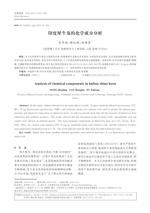
生物资源2019,41(3):245~248Biotic Resources印度犀牛角的化学成分分析宋华玲,谭红琳,祖恩东*(昆明理工大学材料科学与工程学院,云南昆明650093)摘要:本文以印度犀牛角为主要研究对象,利用傅里叶变换红外光谱仪、X射线荧光光谱仪、全自动氨基酸分析仪分析其红外光谱、化学成分等特征,旨在为犀牛角替代品、人工合成品的研究提供部分基础数据。
结果表明:红外光谱中氨基酸、磷脂酸、牛磺酸等相关的吸收峰明显;犀牛角主要的无机成分为CaO、Fe2O3、K2O、ZnO、SiO2等;氨基酸含量为481.01mg/g,药用氨基酸含量丰富,氨基酸组成与标准蛋白的贴近度为0.74。
结果表明犀牛角具有较高的营养价值。
关键词:印度犀牛角;中红外光谱;近红外光谱;X射线荧光光谱;氨基酸中图分类号:O656.9文献标识码:A文章编号:2096‐3491(2019)03‐0245‐04Analysis of chemical components in Indian rhino hornSONG Hualing,TAN Honglin,ZU Endong*(Faculty of Material Science and Engineering,Kunming University of Science and Technology,Kunming650093,Yunnan,China)Abstract:In this paper,Indian rhino horn is the main object of study.Fourier transform infrared spectroscopy(FT‐IR),X‐ray fluorescence spectroscopy(XRF)and automatic amino acid analyzer were used to analyze the infrared spec‐troscopy and chemical composition of rhinoceros horn,in order to provide basic data for the research of rhinoceros horn substitutes and synthetic products.The results showed that the absorption peaks of amino acids,phosphatidic acid and taurine were obvious in infrared spectra.The main inorganic components of rhinoceros horn are CaO,Fe2O3,K2O,ZnO,SiO2,etc.Amino acid content is481.01mg/g,medicinal amino acid content is rich,and the closeness of amino acid composition standard protein is0.74.The result indicates that the rhino horn has high nutritional value.Key words:Indian rhino horn;medium infrared spectrum;near infrared spectrum;X‐ray fluorescence spectrum;amino acid0引言犀牛角为一种名贵的中药材,号称“灵丹妙药”,具有重要的药理作用[1],以犀牛角为原料的工艺品在黑市市场上贵比黄金[2],在其特殊的药用功能及黑市市场暴利的诱引下,非法捕猎活动使犀牛数量不断锐减,犀牛成为受国际保护的珍稀濒危动物。
脂肪酸修饰的纳米颗粒对倍他米松包埋的抗炎性能研究
PharmaceuticalnanotechnologyPolymeric nanoparticles modi fied with fatty acids encapsulating betamethasone for anti-in flammatory treatmentCatarina Oliveira Silva a ,b ,Patrícia Rijo a ,c ,Jesús Molpeceres b ,Isabel Vitória Figueiredo d ,e ,Lia Ascensão f ,Ana So fia Fernandes a ,c ,Amílcar Roberto a ,Catarina Pinto Reis a ,g ,*aCBiOS,Research Center for Biosciences &Health Technologies,Universidade Lusófona,Campo Grande 376,1749-024Lisboa,PortugalbDepartment of Biomedical Sciences,Faculty of Pharmacy,University of Alcalá,Ctra.Universidad Complutense,28871Alcaláde Henares,Spain ciMed.ULisboa,Instituto de Investigação do Medicamento,Faculdade de Farmácia,Universidade de Lisboa,Av.Prof.Gama Pinto,1649-003Lisboa,Portugal dPharmacology and Pharmaceutical Care,Faculty of Pharmacy,Universidade de Coimbra,Azinhaga de Santa Comba,3000-354Coimbra,Portugal eIBILI,Institute for Biomedical Imaging and Life Sciences,Universidade de Coimbra,Azinhaga de Santa Comba,3000-548Coimbra,Portugal fCentro de Estudos do Ambiente e do Mar (CESAM),Universidade de Lisboa,Faculdade de Ciências de Lisboa,CBV,Campo Grande,1949-016Lisboa,Portugal gIBEB,Biophysics and Biomedical Engineering,Faculty of Sciences,Universidade de Lisboa,1749-016,Lisboa,PortugalA R T I C L E I N F OArticle history:Received 13July 2015Accepted 15July 2015Available online 26July 2015Chemical compounds studied in this article:Poly-e -caprolactone (PubChem CID:10.401)Stearic acid (PubChem CID:5281)Oleic acid (PubChem CID:445.639)Pluronic 1F127(PubChem CID:24.751)Betamethasone-21-acetate (PubChem CID:443.967)Betamethasone (PubChem CID:9782)Keywords:Betamethasone-21-acetate NanoparticlesChronic in flammationTransdermal drug delivery Oleic acidPoly-e -caprolactoneA B S T R A C TTopical glucocorticosteroids were incorporated into nanocarrier-based formulations,to overcome side effects of conventional formulations and to achieve maximum skin deposition.Nanoparticulate carriers have the potential to prolong the anti-in flammatory effect and provide higher local concentration of drugs,offering a better solution for treating dermatological conditions and improving patient compliance.Nanoparticles were formulated with poly-e -caprolactone as the polymeric core along with stearic acid as the fatty acid,for incorporation of betamethasone-21-acetate.Oleic acid was applied as the coating fatty acid.Improvement of the drug ef ficacy,and reduction in drug degradation with time in the encapsulated form was examined,while administering it locally through controlled release.Nano-particles were spherical with mean size of 300nm and negatively charged surface.Encapsulation ef ficiency was 90%.Physicochemical stability in aqueous media of the empty and loaded nanoparticles was evaluated for six months.Drug degradation was reduced compared to free drug,after encapsulation into nanoparticles,avoiding the potency decline and promoting a controlled drug release over one month.Fourier transform infrared spectroscopy and thermal analysis con firmed drug entrapment,while cytotoxicity studies performed in vitro on human keratinocytes,Saccharomyces cerevisiae models and Artemia salina,showed a dose –response relationship for nanoparticles and free drug.In all models,drug loaded nanoparticles had a greater inhibitory effect.Nanoparticles increased drug permeation into lipid membranes in vitro .Preliminary safety and permeation studies conducted on rats,showed betamethasone-21-acetate in serum after 48h application of a gel containing nanoparticles.No skin reactions were observed.In conclusion,the developed nanoparticles may be applied as topical treatment,after encapsulation of betamethasone-21-acetate,as nanoparticles promote prolonged drug release,increase drug stability in aqueous media,reducing drug degradation,and increase drug permeability through lipid membranes.ã2015Elsevier B.V.All rights reserved.Abbreviations:BTMA,Betamethasone-21-acetate;DMSO,Dimethyl sulfoxide;DMEM,Dulbecco ’s Modi fied Eagle ’s Medium;DSC,Differential scanning calorimetry;EE,Encapsulation ef ficiency;FTIR,Fourier transform infrared spectroscopy;GCs,Glucocorticosteroids;HaCaT,Human adult low-calcium high-temperature keratinocytes;HPLC,High performance liquid chromatography;MTT,3-(4,5-Dimethylthiazol-2-yl)-2,5-diphenyltetrazolium bromide;NP,Nanoparticles;NSAID,Non steroid anti-in flammatory drugs;OA,Oleic acid;PCL,Poly-e -caprolactone;RC,Refrigeration conditions;RH,Relative humidity;RT,Room temperature;ROS,Reactive oxygen species;SA,Stearic acid;TLC,Thin layer chromatography;YPD,Yeast –peptone –dextrose.*Corresponding author at:CBiOS,Research Center for Biosciences &Health Technologies,Universidade Lusófona,Campo Grande 376,1749-024Lisboa,Portugal.Fax:+351217515598/79.E-mail address:catarina.reis@ulusofona.pt (C.P.Reis)./10.1016/j.ijpharm.2015.07.0440378-5173/ã2015Elsevier B.V.All rights reserved.International Journal of Pharmaceutics 493(2015)271–284Contents lists available at ScienceDirectInternational Journal of Pharmaceuticsj o u r n a l h o m e p a g e :w w w.e l s e v i e r.c o m /l o c a t e /i j p h a rm1.IntroductionTreatment of in flammatory diseases bene fit from a localized therapy accomplished with polymeric-based nanoparticles (Zhang et al.,2013).Recently,we have developed innovative nanoparticles (NP)for treatment of skin diseases,through application of drugs including glucocorticosteroids (GC)(Rosado et al.,2012),non-steroid anti-in flammatory drugs (NSAID)(Pinto Reis et al.,2011),antimicrobial agents (Gomes et al.,2013;Pinto Reis et al.,2013;Rijo et al.,2014)and anticancer drugs for melanoma (unpublished).Glucocorticosteroids (GC)cover a broad spectrum of therapeu-tic actions such as anti-in flammatory,immunosuppressive,anti-proliferative and vasoconstrictive,having also apoptotic and anti-angiogenic effects (Banciu et al.,2006;Lebwohl et al.,2013).The absence of natural GC produced by skin cells is mainly visible in in flammatory diseases,such as atopic dermatitis and psoriasis (Slominski et al.,2013).However,when treating common skin diseases like atopic dermatitis or psoriasis,chronic application of topical corticoste-roids generally leads to local adverse effects such as skin atrophy,rosacea,striae and skin infections.When highly absorbed,systemic side effects (e.g.,hypothalamic-pituitary-adrenal suppression,glaucoma,hyperglycemia and hypertension)appear,compromis-ing the therapeutic effectiveness and patient adherence (Ference and Last,2009).For this study,we chose betamethasone-21-acetate (BTMA)with the structure illustrated in Fig.1,since it is a high-potency synthetic derivative of betamethasone and agonist to the GC-receptors.Betamethasone offers a 10-fold higher potency than hydrocortisone (Arica and Lamprecht,2005),and has been applied through nanosystems for topical and percutaneous permeation,reducing associated side effects (Abdel-Mottaleb et al.,2012;Zhang and Smith,2010).Previously,Abdel-Mottaleb et al.(2012)demonstrated that non-coated polymeric NP work as drug reservoirs,penetrating to 25m m of skin depth (Abdel-Mottaleb et al.,2012),due to limited interaction with skin lipids.In contrast,some reported lipid NP (Zhang and Smith,2010)interact with skin lipids but show many stability problems (e.g.,drug leakage and chemical modi fications during storage).In this study,we provide evidence that the association of both fatty acids and polymers for development of hybrid nanoparticles may counteract individual disadvantages of these materials.In addition,our nanoparticles may also improve local drug delivery to speci fic in flammatory sites in the skin,by reducing hydrolysis and degradation of BTMA and controlling its release from the nano-particles over a prolonged period.The concept of hybrid lipid-polymeric structures was first described for formation of bi-layered membranes (Shen et al.,2000).In the present study,the goal was to develop a stable platform for drug delivery,based on the association of a biodegradable polymer,poly-e -caprolactone (PCL)and stearic and oleic acids as long chain fatty acids.The potential of these carriers is to increase skin permeation.Poly-e -caprolactone (PCL)was used to control drug release,reduce the drug percutaneous penetration and protect the drug from potential photochemical degradation (Pohlmann et al.,2013).In addition,PLC was selected as the core polymer as previous work showed promise as an ideal depot system for prolonged drug release,with appropriate NP size and spherical shape when used for skin applications (Rosado et al.,2012).However,to overcome previous problems,such as the low encapsulation ef ficiency (62%),stearic acid (SA)was added to the core,to improve drug entrapment within the NP structure,also reduce the possibility of burst release (Chen et al.,2001;Lee et al.,2003).Since the penetration of polymeric NP across the skin is hindered by the stratum corneum mechanical barrier properties (Abdel-Mottaleb et al.,2012),oleic acid (OA)was incorporated as the coating lipid,since it has been previously shown to be a skin permeation enhancer and membrane fluidizing agent (Al Abood et al.,2013).OA is also reported to reduce nanoparticle aggregation (Bennet et al.,2012).SA is a saturated fatty acid unlike OA,but both are C 18fatty acids,and are presently approved for skin and food applications (Inoue et al.,2004).In addition,OA and SA are also present in many essential oils,providing higher skin permeation allied with lower toxicity,and have been reported as accepted for cosmetic and alimentary applications and documented by several organizations,such as the International Flavor and Fragrance Association (Herman and Herman,2015).Fig.1.Chemical structures of betamethasone and betamethasone-21-acetate.The modi fication of ester group in C 21of betamethasone-21-acetate,responsible for the molecule ’s high-potency action,is highlighted.272C.O.Silva et al./International Journal of Pharmaceutics 493(2015)271–2842.Materials and methods2.1.MaterialsBetamethasone(MW:392.46g molÀ1)and Betamethasone-21-acetate(MW:434.50g molÀ1)were kindly donated by Hovione S.A. Stearic acid,oleic acid,Pluronic1F127(Poloxamer147),PCL(MW: 14,000g molÀ1),and3-(4,5-dimethylthiazol-2-yl)-2,5-diphenylte-trazolium bromide(MTT)were supplied by Sigma–Aldrich (Steinheim,Germany).Lecithin soybean(>95%phosphatidylcho-line)was supplied by MP Biomedicals(Madrid,Spain)and dodecane(99%purity)was supplied by Panreac(Madrid,Spain). All other compounds and reagents were also of analytical grade. The water used was purified to18.2M V cm at25 C through a Millipore system(Millipore,MA).2.2.Preparation of hybrid nanoparticlesEmpty oleic acid(OA)coated and non-coated NP(i.e.,core NP) were prepared according to a previously described solvent displacement method,with some modifications(Calvo et al., 1997;Shah et al.,2012).Briefly,in a sealed glass beaker (32Â46mm,capacity:25mL,Simax,Czech Republic),an organic phase was prepared by mixing100mg of PCL and4.975mL of acetone,through10min ultrasound exposure(Bandelin Sonorex Super Rk510H,frequency of45kHz).An aliquot of25m L stearic acid(SA)solution in ethanol(0.025%,w/v)was added to the organic phase and allowed to mix for5–10min with magnetic stirring.This solution was immediately poured on10mL aqueous solution of a Pluronic1F127(0.25%,w/v),prepared in similar 25mL glass beaker,under magnetic stirring(1200rpm)for10min. For betamethasone-21-acetate(BTMA)loaded OA NP,the same procedure was conducted except that5mg of BTMA were dissolved in the organic phase.The suspension was stirred for10min and then concentrated under reduced pressure(Rotary evaporator from Heidolph type VV2000,Apeldoorn,Netherlands)to10mL (final volume).All NP were isolated by centrifugation at18550Âg for30min(Hermle Labortechnik Gmbh type Z36HK,Wehingen, Germany)to remove unbound drug.Afterwards,empty and BTMA loaded NP were incubated with80m L of OA,for2h,under constant magnetic stirring.Formulations were made in triplicate to ensure the repeatability of the preparation method.2.3.Physical characterization of the nanoparticlesMean particle size,polydispersity index(PI)and zeta potential of the NP concentrated aqueous suspension were measured with a Coulter Nano-sizer Delsa TM Nano C(Fullerton,CA,USA).Experi-ments were conducted in triplicate for empty core NP,empty OA NP and BTMA-loaded OA NP(n=3).A low value of PI factor(<0.25) indicates a less dispersed NP distribution in size.Results are expressed as mean of measurements on three different batches ÆSD and the empty OA NP and BTMA-loaded OA NP distributions in terms of size as volume.2.4.MorphologySamples of fresh and one-month old empty OA NP and BTMA-loaded OA NP,as an aqueous suspension,were kept in glass vials (capacity:10mL),closed with lid and parafilm,at room tempera-ture(25Æ5 C,RT)and at residual humidity(RH)of60%.An aliquot (10m L)of each sample was mounted on a glass coverslip and left to dry in a desiccator.Afterwards,the sample was coated with a thin layer of gold(500nm thick)and observed on a JEOL5200LV scanning electron microscope(JEOL Ltd.,Tokyo,Japan)at an accelerating voltage of20kV.Images were recorded digitally.2.5.Drug quantificationBTMA was determined by a previously validated reverse-phase HPLC chromatographic method(Petersen et al.,1980).Limit of detection(LOD)and limit of quantification(LOQ)were determined. LOD and LOQ were calculated to be2.91m g/mL and9.71m g/mL, respectively.An Agilent Technologies1200Infinity series was fitted with a dual wavelength UV spectrophotometer detector (Agilent Technologies,Waldbronn,Germany).The mobile phase consisted of methanol and Milli-Q water(60:40%,v/v)using a Zorbax Eclipse Plus C18column(4.6Â100mm,3.5m m,particle size)as the stationary phase.Aflow rate of1.0mL/min and a detection wavelength of240nm were selected.The column conditions were maintained at25 C,with an injection volume of20m L and a run time of15min.Standards for BTMA between 5and60m g/mL were evaluated in triplicate and a calibration curve was found to be y=29.33x+144.82,with R2=0.998.The chro-matographic data was processed using ChemStation software (Agilent Technologies,Waldbronn,Germany).Measurements were made in triplicate(n=3).2.6.Drug loading and encapsulation efficiencyDrug encapsulation efficiency(%)was determined by measur-ing the free drug present in the supernatant(Eq.(1))and the encapsulated drug(Eq.(2)),after rupturing the NP in organic solvents,through exposure to temperature(60 C)and ultrasonic bath(frequency of45kHz).Drug loading efficiency(wt%)was calculated based on the value for drug encapsulation(Eq.(3)). Measurements were made in triplicate with three independent NP batches(n=3).Total amount drugÀAmount free drugTotal amount drugÂ100%(1)Amount encapsulated drugTotal amount drugÂ100%(2) weight of durg in nanoparticleÂ100%(3)2.7.Determination of nanoparticle recovery yieldThree independent batches for BTMA-loaded OA NP(n=3)and OA empty NP(n=3)were lyophilized atÀ50Æ2 C,for24h in FreeZone2.5L Benchtop Freeze Dry System(Labconco,Kansas City, Missouri,USA)and weighted for determination of the NP recovery yield,after production.2.8.In vitro release studiesBTMA-loaded OA NP(400mg,n=3)were lyophilized for24h as described,placed in three stirred(200rpm)amber glass bottles (capacity:50mL),containing50mL of phosphate buffer solution pH5.5(USP XXX)to simulate human skin pH(Knor et al.,2011). Sink conditions were considered during the whole assay,as the solubility of BTMA in aqueous solution is30m g/mL(Kabasakalian et al.,1966).At appropriate time intervals,aliquots of the release medium(300m L)were collected and replaced immediately with fresh buffer.NP were recovered from the supernatant by centrifugation,at18550Âg for30min(Hermle Labortechnik Gmbh type Z36HK,Wehingen,Germany),then returned to the release medium.BTMA concentration at each time point wasC.O.Silva et al./International Journal of Pharmaceutics493(2015)271–284273determined in triplicate using HPLC,according to the methoddescribed in Section2.5.The assay was conducted for one month,until the total amount of drug was released.A standard calibrationcurve,performed with BTMA standards(5–60m g/mL)in phos-phate buffer pH5.5,was found to be y=29.33x+144.82,withR2=0.998.Volume corrections were applied to the drug releaseprofile curve,as mean of three independent measurements ofthree different NP batchesÆSD.During the release studies,BTMA-loaded OA NP and BTMA conversion to BTM was also monitored byHPLC and thin layer chromatography(TLC).TLC is described in thepharmacopeias as a semi-quantitative technique to detectimpurities and degradation products and it is also used for steroidassays,in association with HPLC(Görög,2011).2.9.Stability studies of nanoparticles over timeStability of aqueous suspensions(10mL)of empty OA NP andBTMA-loaded OA NP was evaluated for6months in terms ofphysicochemical characteristics of the formulation,namely size,polydispersity index(PI),zeta potential and pH.Size,PI and zetapotential were measured with a Coulter Nano-sizer Delsa TM NanoC(Fullerton,CA,USA),while pH measurement was conducted witha pH electrode meter(827pH Lab,Metrohm,Switzerland),calibrated daily with buffer solutions pH 4.00Æ0.02and7.00Æ0.02(20 C)ST(Panreac,Spain).Samples were divided intotwo groups with empty OA NP and BTMA-loaded OA NP:(1)emptyOA NP(n=3)and BTMA-loaded OA NP(n=3)were kept understorage at4Æ2 C and residual humidity(RH)of70%(refrigerationconditions,RC);and(2)empty OA NP(n=3)and BTMA-loaded OANP(n=3)were kept at room temperature(25Æ5 C,RT)andresidual humidity(RH)of60%.All samples were stored as aqueoussuspensions of NP,in sealed vials protected from the light andwithout addition of stabilizers or other preservatives.Results arerepresented as mean of measurements of three independentbatchesÆSD.2.10.Interactions between drug and nanoparticlesEmpty OA NP and BTMA-loaded OA NP held in aqueous mediumfor1month at room temperature were selected for the study ofinteractions between drug and OA NP by FTIR spectroscopy andthin layer chromatography(TLC).Samples of fresh and one-monthold NP were kept at room temperature,and then collected andlyophilized to obtain a powder for FTIR analysis.The KBr pelletmethod was used and spectra recorded in an IRAffinity-1FT-IRSpectrophotometer(Shimadzu,Columbia,NY,USA).The pellet wasprepared with a ratio of1:10(w/w)of KBr to NP and left to dry in adesiccator24h before analysis.The following samples werecompared:fresh empty OA NP were compared with raw polymer(poly-e-caprolactone)and fatty acids(stearic acid and oleic acid), and free BTMA was compared with fresh BTMA-loaded OA NP,aswell as a physical mixture of raw components(i.e.,poly-e-caprolactone,stearic acid,oleic acid at1:1:1,w/w)of the nanoparticle formulation(except the drug);in addition,free BTMAwas compared with BTM and one-month old BTMA-loaded OA NPand the raw polymer(poly-e-caprolactone)and fatty acids(stearic acid and oleic acid)were compared with one-month old empty OA NP.2.11.Thermal stability of nanoparticlesDifferential scanning calorimetry(DSC)is described as a technique meant to check the purity of drug and other components,characterization of solid phases and to confirm physicochemical interactions(Görög,2011).Thermal transforma-tions and phase transitions of the nanoparticles were studied by using a Mettler-Toledo DSC-30,TA4000Calorimeter(Columbus, Ohio,USA).Indium was used to calibrate the instrument.Samples were previously lyophilized,weighted(2.0mg)and sealed in an aluminum pan.Free BTMA,empty OA NP,BTMA-loaded OA NP and a physical mixture(1:1,w/w)of BTMA and empty NP were studied. The results were demonstrated as curves of heatflux versus temperature(Celsius degrees, C).A controlled heating rate of 10 C/min under a continuous nitrogen purge(20–30mL/min)and over a temperature range from25to375 C was selected.The number of thermal transitions,the melting point(T m, C)and difference in Gibbs energy(D H,J gÀ1)were also determined.2.12.In vitro permeation studiesParallel artificial membrane permeability assay(PAMPA)was conducted as a preliminary characterization of the role of NP on drug permeability using a96-wellfilter plate Millipore Multi-Screen1IP0.45m m(Darmstadt,Germany).Previously lyophilized empty and BTMA-loaded OA NP(10mg),as well as free BTMA (5mg),were resuspended in Milli-Q water,in order to prepare the stock solutions for the assay.The initial concentration(C0)in the starting solution was50m g/mL for the free BTMA,BTMA-loaded OA NP and free BTMA+empty OA NP(1:1,w/w),which was added (150m L,5%DMSO,v/v)to the donor compartment,to achieve a homogenous covering of the hydrophobic PVDF membrane.The acceptor compartment wasfilled with phosphate solution pH5.5 (300m L).The membrane solution was constituted of soybean lecithin at2%(w/v)prepared in5m L dodecane.After24h incubation,the residual concentration in the donor compartment and the permeated drug concentration in the acceptor compart-ment were also measured.Retention factors(R)(Eq.(4)),perme-ation parameters(C A(t)/C D(0))and permeability coefficients(log P e)(Eq.(5))of the three studied samples were calculated, according to the literature(Markovic et al.,2012):R:1ÀCDðt¼xÞCDðt¼0ÞÀVAVDÂCAðt¼xÞCAðt¼0Þ(4) where V A and V D are,respectively,the volumes in the acceptor and donor wells.logP e:logV DÂV AðV DþV AÞAÂtÀln1ÀCAðt¼xÞ(5) where A is thefilter surface(0.3cm2);t is the incubation time(s); and C A and C D are concentrations in the acceptor and donor wells, respectively(mg mLÀ1cmÀ3).Two measurements were carried out,each comprisingfive replicate samples(n=5),using the same HPLC method described previously in Section2.5(methanol:water60:40%,v/v,as the mobile phase,with Scharlau Kromasil C18column(4.6Â150mm, 5m m,particle size)as the stationary phase).BTMA standards in phosphate solution pH 5.5were repeated and measured in triplicate.A calibration curve equation was found to be y=345.8x+151.05,with a R2=0.998.Results are expressed as meanÆSD.2.13.Toxicity studies2.13.1.MTT assays on HaCaT cell modelCell viability studies were conducted on human keratinocytes (HaCaT cells,CLS Cell Lines Service GmbH,Eppelheim,Germany) using the3-(4,5-dimethylthiazol-2-yl)-2,5-diphenyltetrazolium bromide(MTT)assay(Rijo et al.,2014).Cells were cultured in Dulbecco’s Modified Eagle’s Medium(DMEM)supplemented with 10%fetal bovine serum and1%penicillin/streptomycin solution.To assess the potential cytotoxicity of the NP,cells were seeded onto 96-well plate at a density of5000cells/well to reach the desired274 C.O.Silva et al./International Journal of Pharmaceutics493(2015)271–284confluence.Stock solutions of free BTMA and NP were prepared by dilution in DMSO and DMEM medium respectively,to provide series of different BTMA concentrations(final well concentration): 5–250m g/mL for free BTMA and5–50m g/mL for empty and BTMA-loaded OA NP.For empty OA NP,the equivalent weight of nanoparticles(without drug)was considered,according to the same concentrations used for BTMA-loaded OA NP.Thefinal concentration of DMSO in the cultures did not exceed0.5%(v/v). The cells were exposed to the treatments for24h,then washed twice with PBS and incubated with MTT solution(0.5mg/mL in culture medium)for 2.5h at37 C.Finally,the medium was removed and cells were washed with PBS.DMSO(200m L/well) was added to dissolve the formazan crystals and absorbance was read at595nm(Thermo Scientific Multiskan FC,Shanghai,China). The IC50for BTMA was determined by extrapolating the concentration of BTMA which resulted in50%inhibition of cell growth,using the software OriginPro8(OriginLab Corporation, Northampton,MA,USA).Three independent experiments were carried out,each comprising four replicate cultures(n=4).Results are represented as meanÆSD.2.13.2.Toxicity on Saccharomyces cerevisiae modelCytotoxicity of BTMA and NP was determined against Saccha-romyces cerevisiae(ATCC19763TM)according to the method of Roberto and Caetano(2005).Approximately0.5Â106cells/mL,in yeast–peptone–dextrose(YPD)medium,were exposed to different concentrations of empty OA NP(2m g/mL),BTMA-loaded OA NP(2 and4m g/mL)and free BTMA(5–100m g/mL),in cuvettes(final volume:2mL).Cell cultures grew for5h at30 C in Heidolph Incubator1000with shaker Heidolph Unimax1010,Schwabach, Germany.The cuvettes were vortexed for2s and the absorbance measured at intervals of30min(Thermo Scientific model Evolution300BB,UK).The logarithmic phase from the growth curve was used to evaluate the toxicity,expressed as growth inhibition as percentage of the growth of control cells.Three series of measurements were performed each comprising four replicate cultures(n=4).Results are expressed as meanÆSD.2.13.3.Toxicity on Artemia salina modelThe toxicity of empty NP(2m g/mL),BTMA-loaded NP(2and 4m g/mL)and free BTMA(50and100m g/mL)on Artemia salina was tested according the method described by Zhang et al.(2012),with some small adaptations on the hatching equipment,namely material for covering the compartments.Brine shrimp cysts (80mg)obtained from JBL GmbH&Co.,KG D-67141(Neuhofen, Germany)were hatched in artificial sea water with the salinity concentration of30g/L.The cysts were incubated for48h at30 C. Ten nauplii were transferred into wells of21-well cultures plates containing artificial sea water(final volume/well:1mL).The culture plates were incubated for48h at30 C;after every24h, the number of dead nauplii was counted microscopically.The mortality,expressed in percent,was calculated by using the following Eq.(6):%Mortality¼ðdead nauplii in testÀdead nauplii in controlÞðdead nauplii in controlÞÂ100(6)Three series of measurements were performed in different days,each comprising four replicate groups of ten nauplii(n=4). Results are expressed as meanÆSD.2.14.Preliminary in vivo studiesPreliminary safety and permeation in vivo studies of topical administration of BTMA-loaded OA NP was conducted on male Wistar rats,according to Hayashi et al.(1974),with some modifications.The research was conducted in accordance to the internationally accepted principles for laboratory animal use and care as found in Directive2010/63/EU and the project was approved by the Portuguese Veterinary General Division.Male Wistar rats weighing350–400g were obtained from Charles River (Barcelona,Spain).The animals were maintained with food and water ad libitum and kept at22Æ1 C with controlled12h light/ dark cycle at Faculty of Pharmacy,University of Coimbra.The animals were allowed to adapt to the laboratory for7days before testing.A selected group of animals(n=10)were studied with topical formulation of Carbopol1940gel,prepared as described previously(Gomes et al.,2013),and incorporating0.05%(w/w) BTMA-loaded NP,following the concentration of conventional topical formulations with free BTMA(dose equivalent).The topical formulation was characterized in terms of aspect,pH and apparent viscosity(at100rpm,spindle n. 6,t=90%)by using a DV-I+ Viscometer(Brookfield Engineering Labs.Inc.,Middleboro,MA, USA).BTMA-loaded NP formulation was applied to the dorsal surface of the rats(500mg formulation/animal),by gently rubbing the formulation50times with the indexfinger for each treatment. The presence of BTMA in serum was measured at0,16,24,32, 40and48h,after considering the time period and the results for the amount of drug released obtained in the in vitro release studies and according to previous studies,that demonstrated a maximum peak in plasma for BTMA at approximately1.5h(i.m.,s.d.)and T1/2 around12h(Salem and Najib,2012).Serum samples(300m L)were treated and the drug extracted from the serum according to Goyal et al.(2008).BTMA extracted from serum was determined by HPLC described in Section2.5.2.15.Statistical methodologyResults were expressed as meanÆSD.The significance of differences was assessed using paired sample T-test for mean comparisons between the physicochemical parameters of the formulation control for the stability assay and One-Way ANOVA for multiple comparisons between different systems,for the same concentration,in case of in vitro cytotoxicity.A0.05significance level was adopted for every test.Table1Physicochemical characterization of BTMA-loaded OA NP,empty core NP(no oleic acid)and empty OA NP(without the drug).A comparison is made between a direct and an indirect method for determination of drug encapsulation.Results are expressed as mean of measurements on independent nanoparticle batchesÆSD,expect for polydispersity index(PI),(only means are expressed,n=3).Systems Size(nm)PI Zeta potential(mV)pH Direct method(EE,%)Indirect method(EE,%)BTMA-loaded OA NP306.5Æ15.30.244À7.9Æ9.5 4.3Æ0.285.9Æ10.396.8Æ1.9Core NP335.5Æ48.70.192À13.5Æ9.67.1Æ0.3––Empty OA NP328.2Æ17.20.190À5.3Æ1.3 3.7Æ0.1––C.O.Silva et al./International Journal of Pharmaceutics493(2015)271–284275。
美国洛克希德·马丁公司将研制地球同步碳循环观测任务有效载荷

图3碲镉汞薄膜截面的SBM 测试结果4结论采用扫描电镜分别测试了碲镉汞薄膜经过 粗磨和经过细磨后的表面形貌像和解理面形貌 像,得到了经过两种不同减薄工艺后的碲镉汞 薄膜损伤层信息,获得了非常有价值的实验结 果。
实验结果显示,采用细磨的方式对碲镉汞薄 膜进行减薄产生的损伤层的最大深度比采用粗 磨方式要小得多。
通过扫描电镜对减薄后的碲 镉汞薄膜损伤层进行研究,认识并掌握了碲镉汞 薄膜的损伤层信息,这为后续碲镉汞薄膜减薄 工艺方法和参数的优化与改进提供了重的参 考依据和指导意义。
这也表明采用扫描电镜测 试碲镉汞薄膜的损伤层是评价碲镉汞薄膜减薄 后损伤层的一种非常有效的检测方法。
参考文献[1] 郎艳菊.GSP 晶体加工表面/亚表茴损伤研究p].大连:大连理工大学,2008.[2] 许秀娟,田震.碲镉汞薄膜减薄工艺损伤层的评价方法及应用[J].激光与红外,2〇15, 45(3): 235-239.[3] 康俊勇,黄启圣,王家库,等.HgCdTe 晶片研磨和拋光表面的扫描电镜观察[J].红外技术,1999, 21⑷: 24-27.[4] Li Y , Yi X J, Cai L P. Study on Surface Oxidative Characterization of LPE HgCdTe Epilayer by X-ray Photoelectron Spectroscopy [J]. International Journal of Infrared and Millimeter Waves, 2000, 21(1): 31-37.[5] Madejczyk P, Piotrowski A, Klos K. Surface Smoothness Improvement of HgCdTe Layers Grown by MOCVD [J]. Bulletin of the Polish Academy of Sciences, Technical Sciences, 2009, 57(2): 139-146.[6] Farrell S, Mulpuri V, Rao G, et al. Comparison of the Schaake and Benson Etches to Delineate Dislocations in HgCdTe Layers [J]. Journal of Electronic Materials, 2013, 42(11): 3097-3102.[7] Mollard L, Destefanis G, Rothman J, et al. HgCdTe FPAs Made by Arsenic-ion Implantation [C]. SPIE, 2008, 6940: 69400F.[8] Mollard L, Destefanis G, Bourgeois G, et al. State of p-on-n Arsenic-implanted HgCdTe Technologies [J]. Journal of Electronic Materials, 2011, 40(8): 18301839.新闻动态News美国洛克希德•马丁公司将研制地球同步碳循环观测任务有效载荷据 www.lockheedm 网站报道,美国洛克希德.马丁公司将为美国国家航空航 天局(NASA )的地球同步碳循环观濒(GeoCARB ) 任务研制一台搭载于商业地球同步轨道卫星的 先进红外光谱仪,以帮助科学家们更好地了解 地球的碳循环i 和植被健康状况,相关人员表示,该公司在红外探测和搭载 有教载#方面具有丰富'经验,他们也将与儀克 拉荷马大学、N _A S A 以及科罗拉多.:州立大学合# 完成此次任务.洛克希德•马丁公司位于柏洛阿尔托的先 进技术中心(A TC )将基于詹姆斯.韦伯望远镜 (JWST )的遮..紅外相机(N IR C 爾)谁计来欄这 个搭载有效载荷《与深空探溯:不同,预计于2022 年升空的G eoC A R B 红外光谱仪将用于澜量地球 大气中的二氧化碳、一氧化碳和甲規以及太阳 光诱导..荧光敷据。
石油英语词汇

石油英语词汇(P5)POL 面向问题的语言polar activation 极性活化polar adsorption 极性吸附polar air mass 极地气团polar angle 极角polar anticyclone 极地反气旋polar attraction 极性引力polar cap absorption 极冠吸收polar chart recorder 极坐标图记录器polar chart 极坐标地图polar circle 极圈polar climate 极地气候polar compound 极性化合物polar contact 极化继电器触点polar coordinates 极坐标polar curve 极坐标曲线polar diagramm 极坐标图polar drafter 弧形牵伸装置polar easterlies 极地东风带polar end 极性端polar expansion 线膨胀polar fluid 极性流体polar flux 极化磁通polar form 极坐标形式polar frequency plot 矢量频率图polar group 极性基团polar impurity 极性杂质polar leakage 磁极漏泄polar liquid 极性液体polar material 极性物质polar method 极坐标法polar molecule 极性分子polar monomer 极性单体polar mount antenna 极座架天线polar orbit 极轨道polar organic solvent 极性有机溶剂polar plot 极坐标图polar polymer 极性聚合物polar projection indicator 极投影指示器polar projection 极投影polar racorder 极坐标记录器polar radiation pattern 极坐标辐射图polar radius 极半径polar ray 极射线polar region 极地polar relay 极化继电器polar solid angle 极隅角polar solvent 极性溶剂polar stereographic projection 极射赤平役影polar wandering 极移polar winding 极向缠绕法;极向卷绕polar 极的polar-solvent extraction 极性溶剂萃取法polargraph 极谱仪polari- 极polarigraphy 极谱分析polarimeter 极化计polarimetric analysis 旋光分析polarimetry 旋光测定;测极化polaris 北极星polarisation 极化polariscope 偏振光镜polariscopy =polarimetrypolariton 电磁声子;偏振子polarity chron 极性时polarity coincidency correlator 极性符合相关器polarity effect 极化效应polarity encoding 极性编码polarity epoch 极性期polarity era 极性代polarity event 极性事件polarity hyperinterval 极性特超间隔polarity indicator 极性指示器polarity information 极性信息polarity interval 极性间隔polarity inversion 极性倒转polarity mark 极性标记polarity period 极性纪polarity reversal 极性倒转polarity rock-stratigraphic unit 极性岩石地层单位polarity standard 极性标准polarity subchron 极性亚时polarity subinterval 极性亚间隔polarity subzone 极性亚带polarity superinterval 极性超间隔polarity time scale 极性年表polarity 极性polarity-chronologic unit 极性年代单位polarity-chronostratigraphic unit 极性年代地层单位polarity-inverting amplifier 倒相放大器polarity-reversal horizon 极性倒转面polarium 钯金合金polarizability 极化性polarizable 极化的polarization admittance 极化导纳polarization angle 偏振角polarization capacity 极化电容polarization cell 极化电池polarization color scale 偏光色标polarization color 偏光色polarization corrosion 极化腐蚀polarization diagrams 极化图polarization effect 极化效应polarization ellipse 极化椭圆polarization factor 偏振因数polarization filtering 极化滤波polarization frequency effect 极化频率效应polarization method 偏振法polarization microscope 偏光显微镜polarization photometer 偏光光度计polarization plane 偏振光面polarization potential 极化电位polarization resistance 极化电阻polarization time 极化时间polarization vector 偏振矢量polarization 极化polarize 极化polarized ammeter 极化安培计polarized electrode 极化电极polarized geophone 偏振检波器polarized light 偏振光polarized magnet 极化磁铁polarized near-infrared spectra 偏振近红外谱polarized potential 极化电位polarized relay 极化继电器polarized seismic wave 偏振地震波polarized visible spectra 偏振可见光谱polarizer 偏光镜polarizing angle 极化角polarizing current 极化电流polarizing film 偏振片polarizing light microscope 偏光显微镜polarogram 极谱图polarograph 极谱仪polarographic analysis 极谱分析polarography 极谱法;极谱学polaroid 偏振片polaron 极化子polatization resistance monitor 极化电阻监测仪polder 新辟的低地pole brace 电杆拉线pole changing motor 变极电动机pole clearance 极距pole core 磁极铁心pole derrick 轻便井架pole diagram 极性图pole effect 电极效应pole excitation 极激励pole face 极面pole finding paper 试极纸pole guy 电杆拉线pole line 架空线pole man 消防云梯操纵手pole mast 单杆桅;杆式井架pole piece 极靴pole reduction 磁极校正pole saturation 极化饱和pole shoe bore 极靴孔pole shoe tip 极靴边pole shoe 极靴pole surface 磁极面pole terminal 极端pole 杆;测杆;极pole-dipole array 单极-偶极排列pole-pole array 单极-单极排列pole-pole curve 单极-单极曲线pole-pole sounding curve 单极-单极电测深曲线pole-pole transformed curve 单极-单极变换曲线pole-type mast 杆式井架poled 连接的polhode 本体极迹police 校正;警察poliched rod eye 悬绳器policy capture 策略俘获技术policy clause 保险条款policy decision 方针决策policy function 策略函数policy holder 保险客户policy making 决定政策policy space 策略空间policy 政策;策略;保险单poling 立杆;成极;还原;吹气;支撑polish nipple 抛光短节Polish notation 波兰表示法polish rod clamp 光杆吊环polish rod 光杆polish softener 细软化器polish 抛光polished hore receptacle 抛光孔座polished nipple 抛光短节polished OD 抛光外圆polished piston 抛光活塞polished rod capacity 光杆负荷能力polished rod head 光杆头polished rod liner 光杆衬筒polished rod load 光杆负荷polished rod stuffing box 光杆盘根盒polished rod 光杆polished section 抛光片;磨光片polished surface 抛光面polisher 抛光机;高纯度水处理装置polishing diatomaceous filtration 硅藻土精过滤polishing roll 抛光辊;轧光辊polishing scratch 磨痕political risk 政治风险politics 政治;政纲;策略polje lakle 炭岩盆地湖polje 坡立谷poll tax 人头税poll 轮询Pollard method 波拉德方法Pollard-type fracture 波拉德型裂缝polled interrupt 轮询中断pollen analysis 花粉分析pollen diagram 花粉谱pollen frequency 花粉总数pollen grain 花粉粒pollen granule 花粉粒pollen mixture 混合花粉pollen profile 花粉剖面pollen sac 花粉囊pollen tetrahedron 四角锥形花粉pollen tetred 四分花粉pollen tube 花粉管pollen 花粉pollenites 化石花粉大类Pollina 花粉门polling interval 轮询间隔polling 查询pollinium 花粉块Pollognathus 强颚牙形石属pollutant emission 污染物排放pollutant 污染物polluted ground 污染的土地polluter 污染物质;污染者pollution control 污染控制pollution exhaust criteria 排污标准pollution free fuel 无污染燃料pollution free 无污染的pollution index 污染指数pollution regulation 环境保护条例pollution source 污染源pollution tax 污染税pollution 沾污pollution-carrying 带有污染的pollution-free energy source 无污染能源polohalocarbon 多卤烃polonium 钋polor absorption 极性吸收poly allyl glycidylether 聚烯丙基缩水甘油醚poly carboxylic acid 聚羧酸poly =poljepoly 聚芳醚醚酮poly- 多poly-4-vinyl pridinium chloride 聚-4-乙烯吡啶氯化物poly-a-pyrrolidone fibre 聚-a-吡咯烷酮纤维poly-m-methyl styrene 聚间甲基苯乙烯poly-n-butyl methacrylate 聚甲基丙烯酸丁酯poly-organic scale inhibitor 聚合有机防垢剂polya =poljepolyacetal 聚缩醛polyacid 多元酸polyacrylamide 聚丙烯酰胺polyacrylate 聚丙烯酸酯polyacrylate-type VI improver 聚丙烯酸酯型粘度指数改进剂polyacrylic plastics 聚丙烯酸类塑料polyacrylonitrile 聚丙烯腈polyact =polyactin 多射骨针polyad 多合体花粉polyaddition 加聚作用Polyadopollenites 多胞粉属polyalcohol 多元醇polyalcohols 聚醇类polyalkane 聚链烷polyalkyl methacrylate 聚甲基丙烯酸烷基酯polyallomer 同质异晶聚合物;异质同晶聚合物polyalphabetic cipher 多字码密码polyamidation 聚酰胺化polyamide fibre 聚酰胺纤维polyamide 聚酰胺polyamide-imide resin 聚酰胺-酰亚胺树脂polyamine polymer 聚胺聚合物polyamine 多胺polyampholyte 聚两性电解质polyamphoteric electrolyte 聚两性电解质polyanion 聚阴离子polyanionic cellulosic polymer 聚阴离子纤维素聚合物polyaroylation 多芳酰基化polyarylamide 聚芳基酰胺polyarylate 聚芳酯polyarylation 多芳基化反应polyarylether 聚芳醚polyaryletherketone 聚芳醚酮polyarylsulfone 聚芳砜polyarylsulphone 聚芒砜polyatomic alcohol 多元醇polyatomic molecule 多原子分子polyatomic phenol 多元酚polyatron 多阳极计数放电管polybase crude 混合基原油polybasic carboxylic acid 多元羧酸polyblend fibre 聚合物混纺纤维polyblend 聚合混合物polyborane 聚硼烷polybutadiene 聚丁二烯polybutene oil 聚丁烯合成润滑油polybutene sulfonate 聚丁烯磺酸盐polybutene 聚丁烯polybutene-1 聚丁烯-1polybutylene terephthalate 聚对苯二甲酸丁二醇酯polybutylene terephthalate 聚对苯二甲酸丁二酯polybutylene 聚丁烯polybutyrolactam 聚丁内酰胺polycaprinlactam 聚癸内酰胺polycaprolactam 聚己内酰胺polycaprolactone glycol 聚已内酯乙二醇polycapronmide 聚己酸酯polycarbamate 聚氨基甲酸酯polycarboimide 聚碳酰亚胺polycarbonate resin 聚碳酸酯树酯polycarbonate 聚碳酸酯polycarpeae 显花植物polycathode counter tube 多阴极计数管polycation 聚阳离子Polycaulodus 多茎牙形石属Polycene 多新世Polychaeta 多毛纲Polychaete burrow 多毛目潜穴polychaetous 多毛目的polychlorinated biphenyl 多氯联苯polychloroprene 聚氯丁烯;氯丁橡胶polychlorostyrene 聚氯苯乙烯polychlorotrifluoroethylene 聚三氟氯乙烯polychroism 多色polychromatic beam 色束polychromatic fibre 热敏变色纤维polychromatic spectrum 多色谱polychromatic 多色的polychrome graphics display 彩色图形显示polychrome 彩色;多色的Polycingulatisporites 多环三缝孢属polyclinal fold 多斜褶皱polycoagulant 凝聚剂Polycolpits 多沟粉属polycomponent 多组分polycondensation 缩聚polycondensed aromatic rings 聚缩芳香烃环polyconic chart 多圆锥投影地图polyconic projection 多圆锥投影polycore cable 多芯电缆polycrystal 多晶体polycrystalline diamond compact bit 聚晶金刚石复合片钻头polycrystalline diamond 多晶金刚石polycrystalline zirconium dioxide fibre 多晶二氧化锆纤维polycrystalline 聚晶的polycycle 多旋回polycyclic aromatic bydrocarbon 多环芳香烃polycyclic aromatics 多环芳香烃polycyclic compund 多环化合物polycyclic geosyncline 多旋回地槽polycyclic hydrocarbon 多环烃polycyclic landform 多旋回地形polycyclic naphthene 多环烷烃polycyclic orogenesis 多旋回造山运动polycyclic ring 多核环polycyclic saturated hydrocarbon 多环饱和烃polycyclic system 多环体系polycyclic triterpenoids 多环三萜类化合物polycyclic 多旋回的;多环的;多相的;多周期的Polycyclolithus 聚环颗石polycyoalkane 多环烷烃polydeformation tectonic pattern 复变形构造模式polydemic 广居的polydiexodina 复通道属polydirectional 多方向的polydispersity 多分散性polydithiazole 聚二噻唑polydymite 辉镍矿polyelectrolyte filter 聚合电解质过滤器polyelectrolyte pretreatment 聚合电解质预处理polyelectrolyte 聚合电解质;高电解质polyene 聚烯polyenetic topography 复成地形polyenic sediment 多源沉积物polyenic 复成的polyepoxide 聚环氧化物polyeric chelate 聚合螯合体polyester polyol 聚酯多元醇polyester resin 聚酯树脂polyester synthetic lubricant 聚酯合成润滑剂polyester 聚酯polyester-imide 聚酯酰亚胺polyester-polyamide alloy fibre 聚酯-聚酰胺混合体纤维polyester-styrene-foam 聚酯-苯乙烯泡沫polyesteramide fibre 聚酰胺酯纤维polyestercarbonate 聚酯碳酸酯polyesterification 聚酯化polyether glycol 聚醚多元醇polyether oil 聚醚油polyether polyol 聚醚多醇polyether 聚醚polyetheretherketone 聚醚醚酮polyetherimide 聚醚酰亚胺polyetherization 多醚化polyetherketone 聚醚酮polyetherketoneetherketoneketone 聚醚酮醚酮酮polyethers 聚醚polyethersulfone 聚醚砜polyethoxy alkylamine surfactant 聚乙氧基烷基表面活性剂polyethoxy polypropoxy surfactant 聚乙氧基聚丙氧基型表面活性剂polyethylene glycol 聚乙二醇polyethylene insulation 聚乙烯绝缘polyethylene jacket 聚乙烯套polyethylene monofilament 聚乙烯单丝polyethylene oxide 聚环氧乙烷polyethylene pipe 聚乙烯管polyethylene polyamine 多亚乙基多胺polyethylene terephthalate 聚对苯二甲酸乙二醇酯polyethylene terephthalate 聚对苯二甲酸乙二酯polyethylene 聚乙烯polyethyleneimine 聚乙烯亚胺polyfactorial 多因子的polyfilament yarn 复丝纱线polyfoam spacer 泡沫塑料衬垫polyfoam 泡沫塑料polyformal 聚缩甲醛polyformaldehyde resin 聚甲醛树脂polyformaldehyde 聚甲醛polyfunctional compound 多官能化合物polyfurnace 聚合炉polygene 多源的polygenetic conglomerate 复成砾岩polygenetic 复成的polygenous 复成的polygeosyncline 复地槽polyglass 苯乙烯塑料polyglycol distearate 聚乙二醇二硬脂酸酯polyglycol 聚乙二醇polyglycollide fibre 聚乙交酯纤维Polygnathellus 小多颚牙形石属Polygnathodella 小拟多颚牙形石属Polygnathoides 拟多颚牙形石属polygon data encoding 多角数据编码polygon misclosure 导线闭合差polygon 多角形Polygonacidites 蓼粉属polygonal angle 导线角polygonal dislocation 多角状位错polygonal drainage pattern 多角状水系polygonal line 折线polygonal marking 地面龟裂polygonal point 导线点polygonal structure 多边形构造;龟裂构造polygonal traverse 多角导线polygonal 多边形的polygonization 多边形化polygonmetric method 导线测量法polygonmetric point 导线点polygonmetry 导线测量polygorskite 坡缕石polygraph 复写器;多种波动描记器;测谎器;著作集polyhalide 多卤化物polyhalite 杂卤石polyhalogenohydrocarbon 多卤烃polyhalohydrocarbon 多卤烃polyhedra polyhedron 的复数polyhedral pore 多面体型孔隙polyhedron 多面体polyhexamethylene adipamide 聚己二酰己二胺polyhybrid 多混合;多混合波导联接polyhydrate 多水合物polyhydric alcohol 多元醇polyhydric phenol 多元酚polyhydroxybacteriabopane 多羟基细菌霍烷polyimide film 聚酰亚胺胺薄膜polyimide 聚酰亚胺polyion 聚离子polyiron 铁粉polyisobutene 聚异丁烯polyisobutylene 聚异丁烯polyisocyanate 聚异氰酸酯polyisocyanurate 聚异氰脲酯polyisophthaloyl metaphenylene diamide fibre 聚间苯二甲酰间苯二胺纤维polyisoprene 聚异戊二烯polykaryotic 多核的Polyken coating 玻利肯公司塑料胶粘带防腐层polykraft moisture barrier 多层牛皮纸防潮层polylauryl methacrylate 聚十二基异丁烯酸盐polylitharenite 复岩屑砂屑岩Polylophodonta 多冠脊牙形石属polymer alloy 聚合物合金polymer augmented waterflood 聚合物加强注水驱油polymer blend 高分子共混物polymer blending 聚合物共混polymer brine completion fluid 聚合物盐水完井液polymer builder 聚合物助剂polymer chips 聚合体切片polymer clump 聚合物团块polymer degradation 聚合物降解polymer dielectric 聚合物电介质polymer diverter 聚合物转向剂polymer drag reducer 聚合物减阻剂polymer emulsion 聚合物乳状液polymer flexible membrane lining 聚合物柔性膜衬里polymer flooding 聚合物驱油polymer gasoline 叠合汽油polymer gel 聚合物冻胶polymer gelled fluid 聚合物稠化液polymer grade ethylene 聚合级乙烯polymer hydration 聚合物水化polymer loading 聚合物用量polymer modification 聚合物改性polymer molecule 聚合物分子polymer mud 聚合物泥浆polymer radical 聚合物游离基polymer residue 聚合物残渣polymer shear mixing system 聚合物剪切混合装置polymer solution 聚合物溶液polymer transition 聚合物转变polymer viscosifier 聚合物增稠剂polymer viscosity 聚合物粘度polymer waterflooding 注聚合物溶液polymer 聚合物;多聚物polymer-making autoclave 压热聚合釜polymer-melt temperature 聚合物熔体温度polymer-polyelectrolyte drilling fluid system 聚合物-聚电解质钻井液polymer-solvent interaction 聚合物-溶剂相互作用polymer-through-put rate 聚合物通过速率polymerbitumen 聚合沥青polymeric additive 聚合添加剂polymeric cationic clay stabilizer 聚合阳离子粘土稳定剂polymeric colloid 聚合物胶体polymeric drag reducing additive 聚合物减阻加添剂polymeric flocculant 高分子絮凝剂polymeric material 聚合材料polymeric modifier 聚合改性剂polymeric plasticizer 高分子型增塑剂polymeric pour point depressant additive 聚合物降倾点添加剂polymeric thickener 聚合增稠剂polymeric viscosifier 聚合增稠剂polymeric 聚合的polymeride =polymerpolymerisation 聚合polymerism 聚合polymerization -depolymerization equilibrium 聚合-解聚平衡polymerization accelerator 聚合加速剂polymerization activator 聚合活化剂polymerization autoclave 压热聚合釜polymerization catalyst 聚合催化剂polymerization floor temperature 聚合下限温度polymerization in filament form 长丝状聚合法polymerization in homogeneous phase 均相聚合polymerization inhibitor 阻聚剂polymerization initiator 聚合引发剂polymerization kinetics 聚合动力学polymerization mechanism 聚合机理polymerization rate 聚合速率polymerization reaction 聚合反应polymerization regulator 聚合调节剂polymerization retarder 聚合抑止剂polymerization 聚合polymerization-coupling reactant 聚合偶联剂polymerizer 聚合剂;聚合器;高温焙烘机polymetamorphic 多相变质的polymetamorphism 多相变质polymetaxylene adipamide fibre 聚己二酰间苯二甲胺纤维polymeter 多能湿度表;多能测定计polymethacrylate 聚甲基丙烯酸酯polymethoxy acetal 聚甲氧基甲缩醇;聚甲氧基缩醛polymethyl methacrylate 聚甲基丙烯酸甲酯polymethylene 聚甲烯polymethyleneimine 聚亚甲基亚胺polymethylmethacrylate 聚甲基丙烯酸甲酯polymethylpentene 聚甲基戊烯polymethylstyrene 聚甲基苯乙烯polymict 复矿碎屑岩polymictic 多杂质的;复矿的polymkeric substance 聚合物polymolecularity 多分子性;高分散性polymorph 多形体;多晶型物polymorphic inversion 多形转换polymorphism 多形性;多型polymorphy 多晶形现象polynary 多元的Polynathodella 小似多口牙形石属Polynathus 多口牙形石属polynigritite 细粒分散煤化沥青polynite 蒙脱土polynome 多项式polynomial adjustment 多项式平差polynomial discriminant function 多项式判别函数polynomial expansion 多项式展开polynomial expression 多项式polynomial fitting method 多项式拟合方法polynomial function 多项式函数polynomial interpolation 多项式插值polynomial model equation 多项式模型方程polynomial regression 多项式回归polynomial trend surface analysis 多项式趋势面分析polynomial 多项式polynorbornene rubber 聚乙叉降冰片烯橡胶Polynucella 多核藻属polynuclear aromatic hydrocarbon 多环芳香烃polynuclear aromatics 多环芳香烃polynuclear compounds 多核化合物polynuclear 多核的polyol 多元醇polyolefin resin 聚烯烃树脂polyolefin 聚烯烃polyolefins 聚烯烃类polyolein fiber 聚烯烃纤维polyorganic acid 聚合有机酸polyose 多糖polyoxyethylene ether 聚氧乙烯醚polyoxyethylene 聚氧化乙烯polyoxymethylene resin 聚甲醛树酯polyoxymethylene 聚甲醛polyoxypropyleneamide 聚氧丙烯酰胺polyparagenetic 多共生的polyparium 珊瑚群体polypeptide 多肽polypeptied chain 多肽链polyperoxide 聚过氧化物polyphagous 多食性的polyphase current 多相电流polyphase deformation 多相变形polyphase equilibrium 多相平衡polyphase flow 多相流polyphase induction motor 多相感应电动机polyphase metamorphism 多相变质作用polyphase motor 多相电动机polyphase 多相;多期的polyphasic flow 多相流polyphasic orogenic cycle 多相造山旋回polyphasic-flow regime 多相流型polyphenol 多酚polyphenylene oxide 聚苯醚polyphenylene sulfide 聚苯硫polyphosphate 多磷酸盐polyphyric 多种斑晶的polypivalolactone 聚物戊内酯Polyplacognathus 多盾齿牙形石属polyplanar 多晶平面polyplane 多翼飞机polyplant 聚合装置polyplexer 天线转接开关polypoary 珊瑚群体Polypodiaceae 水龙骨科Polypodiaceoisporites 具环水龙骨孢Polypodiidites 水龙骨孢属Polyporina 多孔粉属polyprene 聚戊二烯polypropylene glycol 聚丙二醇polypropylene impact copolymer 聚丙烯耐冲击共聚物polypropylene random copolymer 聚丙烯无规共聚物polypropylene soak 聚丙烯浸渍polypropylene 聚丙烯polypropyleneoxide 聚环氧丙烷polyprotonic acid 多元酸polyquaternary amine 聚季铵polyradical 聚合基polyreaction 聚合反应polyrod 聚苯乙烯棒polysaccharide deflocculant 多糖类反絮凝剂polysaccharide salt mud 多糖盐泥浆polysaccharide 多糖polysaccharose 多糖polysemy 多义性polysilicic acid chain 聚硅酸链polysilicon 多晶硅polysiloxane 聚硅氧烷polysiloxane-aluminium soap grease 聚硅氧烷铝皂润滑酯polysleeve 多路的polysoap 聚皂polysomy 多体性polyspast 滑车组polyspeed 多种速度;均匀调节速度polyspory 多孢子现象polystage amplifier 多级放大器polystenobath 狭深水性的polystenohaline 狭多盐生物polystyle 多柱式polystyrene film capacitor 聚苯乙烯电容器polystyrene foam 聚苯乙烯泡沫塑料polystyrene 聚苯乙烯polystyrol 聚苯乙烯polysulfide 多硫化合物polysulfonate copolymer 聚磺酸酯共聚物polysulfonate 聚磺酸盐polysulfone 聚砜polytechnic twist device 多能加捻器polytechnic 多种工艺的polytectonic 多期构造的polyterpene resin 多萜树脂polyterpene 多萜polytetrafluoroethylene 聚四氟乙烯polytetramethylene glycol 聚丁二醇polythene =polyethylenepolytope 多面体;可剖分空间;多胞形polytrifluorostyrene 聚三氟苯乙烯polytrope 多变性polytropic compression 多变压缩polytropic head 多变压头polytropic process 多变过程polytropic 多变的polytropism 多晶polytropy 多变现象polytypism 多型性polyurea 聚脲polyurethane foam insulation 聚氨酯泡沫保温polyurethane foam separator 聚氨酯泡沫分离器polyurethane foam 聚氨酯泡沫体;聚氨基甲酸酯泡沫polyurethane insulation coating 聚氨酯保温层polyurethane leather 聚氨基甲酸酯合成革polyurethane resin paint 聚氨酯树脂漆polyurethane resin 聚氨基甲酸酯树酯polyurethane rubber 聚氨酯橡胶polyurethane sponge 聚氨酯海绵polyurethane spray foam 喷涂聚氨酯泡沫polyurethane thermoplastic elastomer 聚氨基甲酸酯热塑性弹性体polyurethane 聚氨酯polyurethanetar coating 聚氨酯-焦油涂层polyuronic acid 多缩糖醛酸polyuronide 多糖醛酸苷polyvalent alcohol 多元醇polyvalent metal ion 多价金属离子polyvalent 多价的polyvinyl acetate 聚乙酸乙烯酯polyvinyl alcohol 聚氯乙烯polyvinyl butyral 聚乙烯醇缩丁醛polyvinyl chloride acetate 聚氯乙烯-醋酸乙烯酯polyvinyl chloride foam 聚氯乙烯泡沫塑料polyvinyl chloride lined tubing 聚氯乙烯衬里油管polyvinyl chloride 聚氯乙烯polyvinyl dichloride 聚二氯乙烯polyvinyl ethyl ether 聚乙烯基乙醚polyvinyl fluoride 聚氟乙烯polyvinyl isobutyl ether 聚乙烯基异丁基醚polyvinyl methyl ether 聚乙烯基甲基醚;聚乙烯甲醚polyvinyl methyl ethermaleic anhydride 聚乙烯甲基醚/马来酸酐polyvinyl methylether-maleic anhydride copolymer 聚乙烯甲基醚-马来酐共聚物polyvinyl plastic core 聚乙烯芯polyvinyl pyrrolidone 聚乙烯基吡咯烷酮polyvinyl stearate 聚硬脂酸乙烯酯polyvinyl 聚乙烯化合物polyvinylidene fluoride 聚偏二氟乙烯polyvinylidene 聚乙二烯polyxyethylated alcohol 聚氧乙烯醇醚polyxyethylated alkylphenol 聚氧乙烯烷基酚醚polyzoa 群虫polyzoan 苔藓虫polyzooid 群虫个体polzenite 橄黄煌岩Pomarangina 波马兰哈属pompier belt 带钩安全带pompier chain 挂钩梯链pompier ladder 挂钩梯PON 粒状有机氮ponceau 深红;酸性朱poncelet 百千克米秒pond 池塘;圈闭pondage 蓄水量ponded basin 阻塞盆地ponded calcareous turbidite 下沉深水钙质浊积岩ponded stream 阻塞河ponderabld 可衡量的;可估量的ponderation 沉思;考虑;估量pondlet 小水池ponor 落水洞Pontian movement 蓬蒂运动Pontian stage 蓬蒂阶Pontian 蓬蒂阶pontic 深海静水Pontilithus 海颗石pontium 深海群落Pontocypris 海星介属pontoon barge 平底船pontoon bridge 浮桥pontoon crane 浮吊pontoon manhole 浮船人孔pontoon roof 浮顶pontoon section 船舱pontoon string 浮筒排pontoon type floating roof 浮船式浮顶pontoon 浮筒;浮桥;起重机船;平底船;浮码头空气舱pontoon-deck-tank 浮顶油罐pontophilus 栖深海的Pontryagin maximum principle 庞特利雅金极大值原理pony collar 小接箍pony insulator 小绝缘子pony mixer 小混合器pony packer 小直径封隔器pony rod 短抽油杆pony sill 底座架pony 小型的;辅助的pony-size 小型的pony-substructure 小型井架底座ponza-trachyte 霓辉粗面岩ponzite 霓辉粗面岩POO 邮政汇票POOH 从井中起出pool cathode mercury-arc rectifier tube 汞弧阴极水银整流管pool cathode 汞弧阴极pool description 油气藏描述pool opener 新油层第一口产油井pool tube 汞弧整流器pool 油藏;联营pooled curde oil 矿藏原油pooled data 合并数据pooled gas 矿藏天然气pooled hydrocarbons 矿藏油气pooled sample statistics 合并样本统计量pooled sample variance 合并样本方差pooled sampling 集合采样pooled variance 合并方差pooling angle 集中合成角pooling constant 集中合成常数pooling of interest method 合营法pooling quality rating 集中合成质量评定pooling 集中合成pooling-of-interest 集合经营poop shot 低速带测量poop 舵楼甲板;船尾楼;尖锐脉冲poor casing seat 套管鞋坐不稳的poor combustion 不完全燃烧poor concreate 水泥少的混凝土poor conductor 不良导体poor efficiency 低效率poor gas 贫气poor mud 劣质钻井液poor oil 低质量油料poor perforation 射孔质量不良poor reflector 不良反瘠土;施工条件不好的土壤poor 贫的;稀少的;劣质的;含量少的poor-boy core barrel 手工制管式取心筒poor-boy job 一揽子承包作业poor-boy rig 浅井钻机poor-man anchor 尾管式气锚poor-quality water 劣质水poorly graded 分级差的;分选差的poorly rounded 磨圆度差的poorly sorted 分选差的pop safety valve 紧急安全阀pop valve 突开阀pop 发射POP 开泵POP 直立式海洋平台pop-off valve 安全阀pop-up buoy 急出急没浮筒pop-up 反射popcorn polymerization 玉米花状聚合poping 突然开启poppet pressure 支架压力poppet valve 提动阀poppet 随转尾座;托架;枕木;执行架;提升阀poppethead 随转尾座popping pressure 突开压力popping 激发;突然鸣叫;突然跳出popple 起光翻滚;波动;起伏popualtion regression 总体回归popular edition 普及版popularity 通俗性;普及popularization 普及population coefficient of variation 总体变导系数population correlation coefficient 总体相关系数population covariance 总体协方差population density index 人口稠密指数population distribution 总体分布population mean point 总体样中点population mean 总平均值population parameter 总体参数population variance 总方差population 总体;人口;密度;群种popwer station 发电站Poraspis 孔甲鱼属porcelain bobbin 瓷筒子porcelain clay 瓷土porcelain earth 高岭土porcelain filter 陶瓷过滤器porcelain insulator 陶瓷绝缘子porcelain liner 瓷衬里porcelain nozzle 瓷质纺丝头porcelain 瓷器;瓷的;脆的porcelaneous 瓷状的porcelanic 瓷状的porcelanous 瓷状的porcellanite 中柱石porch 边缘porcupine 刮管器pore abundance 孔隙发育程度pore body radius 孔隙半径pore boundary 孔隙边界pore bridging 孔隙搭桥pore bulge 孔隙扩大pore cast 孔隙铸模pore cement 孔隙胶结物pore channel 孔隙通道pore character 孔隙特征pore cluster 孔隙簇pore compressibility 孔隙压缩性pore configuration 孔隙形状;孔隙结构pore connectivity 孔隙连通性pore constriction 孔隙喉道pore coordination number 孔隙配位数pore cross-section 孔隙截面pore diameter distribution 孔径分布pore diameter 孔隙直径pore domain 孔隙域pore doublet model 孔隙对模型pore entrance radius 孔隙入口半径pore entry radius 孔隙入口半径pore entryway 孔隙入口pore exit 孔隙出口pore filling 孔隙充填pore fluid 孔隙流体pore geometry factor 孔隙几何因数pore geometry 孔隙几何形状pore interconnection 孔间通道pore length 孔隙长度pore level flow 孔隙内流动pore level model 孔隙级模型pore lining 孔壁附着pore membrane 孔膜pore morpholohy 孔隙形态pore network 孔隙网络pore opening size 孔径pore passage 孔道pore path 孔道pore pressure 孔隙压力pore radius 孔隙半径pore restriction 孔隙收缩pore shape 孔隙形状pore size determination 孔隙大小测定pore size distribution 孔隙大小分布pore sorting 孔隙分选pore space characterization 孔隙空间特征描述pore space 孔隙空间pore structure 孔隙结构pore surface 孔隙表面pore texture 孔隙结构pore throat 孔喉pore tortuosity 孔隙扭曲性pore velocity 孔隙流速pore volume compressibility 孔隙体积压缩系数pore volume injected 注入的孔隙体积倍数pore volume 孔隙体积pore waist 孔隙收缩颈pore wall 孔壁pore water head 孔隙水压头pore water pressure 孔隙水压力pore water 孔隙水pore width 孔隙宽度pore 孔隙pore-aperture radius 孔隙开口半径pore-body 孔隙体pore-by-pore displacement efficiency 逐孔驱替效率pore-center network 孔隙中心网络pore-entry diameter 孔隙入口直径pore-fluid pressure 孔隙流体压力pore-volume-weighted pressure 孔隙体积加权压力pore-wall curvature 孔壁曲率pored 有孔的Porifera 多孔动物门;海绵动物门porigelinite 多孔腐殖体poriness 多孔性porodic 非晶质的porodite 变质火山碎屑岩poroelastic medium 多孔弹性介质porometer 孔隙度仪poroperm characteristics 孔渗特征Poroplanites 凹褶孢属poroscope 测孔计porosimeter 孔隙度仪porosint 多孔材料porosity communication 孔隙连通porosity cutoff 孔隙度下限porosity enhancement 孔隙度放大porosity exponent 孔隙度指数porosity frequency distribution 孔隙度频率分布porosity gradient 孔隙梯度porosity isopleth map 孔隙度等值线图porosity log 孔隙度测井porosity overlay 孔隙度叠合图porosity pod 多孔性扁透镜体porosity reduction 孔隙度下降porosity thickness 孔隙地层厚度porosity trap 孔隙性圈闭porosity 孔隙度;空隙度;孔率porosity-compressibility product 孔隙度-综合压缩系数乘积Porosphaera 孔球轮藻属porous absorber 多孔吸收剂porous adsorbent 多孔吸附剂porous body 多孔体porous cement 孔隙胶结物porous channel 孔道porous cup tensiometer 多孔杯张力仪porous diaphragm device 多孔隔膜仪porous formation 多孔地层porous fractured medium 孔隙裂缝性介质porous glass disk 多孔玻璃圆盘porous ground 多孔岩层porous hydrocarbon-bearing medium 多孔含烃介质porous interval 孔隙层段porous layer 多孔岩层porous mass 多孔物质porous medium 多孔介质porous membrane 多孔滤膜porous model 多孔模型porous mold 多孔模porous network 多孔网络porous pay zone 多孔产层porous plate 多孔板porous pot 多孔瓶porous rock 多孔岩石porous structure 多孔结构porous vesicular surface 多孔表层porous walled breakwater 多孔墙式防波堤porous water sand 多孔含水砂层porous 孔隙的porphin 卟吩porphyrin complex 卟啉络合物porphyrin 卟啉porphyrinogen 卟啉原porphyrinogenic steroid 生卟啉甾类porphyrite 玢岩;斜长斑岩porphyritic breccia 斑状角砾岩porphyritic crystal 斑晶porphyritic 斑状porphyroblast 斑状变晶porphyroblastic texture 变斑晶结构porphyroclast 残碎斑晶porphyroclastic texture 碎斑结构porphyrocrystallic 斑状的porphyrocrystic 斑晶的porphyrogranulitic texture 斑粒结构porphyroid neomorphism 残斑新生变形作用porphyroid 残斑岩porphyrotopic 斑状的porphyry 斑岩porpoise 海豚式游动;前后震动porpoising 跳跃颠簸porporino 血卟啉;黄粉金port anchorage 港内锚地port and starboard 左舷及右舷port authority 港务局port charge 港口费port collar 带孔短节port conservancy 港湾管理局port depot 港口油库port duties 港税port facilities 港湾设施port hand buoy 左舷浮标port hand 左舷port installations 港口设施port of coaling 装煤港port of definite anchorage 定泊港port of destination 到达港port of entry 进口港port of exportation 输出港port of importation 输入港port of loading 装货港口port of refuge 避难港port of sailing 启航港port of shipment 装货港port of transshipment 中转港port of unloading 卸货港port office 港务局port operation 港湾经营port outlet 出口port side 左舷port tarifff 港口费PORT 便携的port 汽门portability 轻便性portable acetylene generator 移动式乙炔发生器portable appliance 手提式仪器portable arc welding machine 移动式弧焊机portable asphalt plant 移动式沥青混合设备portable beam 活动梁portable breakout equipment 轻便式拆装设备portable calibration jig 便携式刻度夹portable computer 便携式计算机portable crane 轻便起重机portable derrick 轻便井架portable disk pack 活动磁盘组portable drawworks 轻便绞车portable drill 轻便钻床portable drilling rig 轻便钻机portable environmental calibrator 轻便式刻度器portable field reflectance spectrometer 轻便式野外反射率分光仪portable field spectrometer 便携式野外能谱仪portable filtration unit 移动式过滤装置portable fire extinguishing system 移动式灭火系统portable fire pump 手抬消防泵portable hatch beam 舱口活动梁portable land source 便携式陆地震源portable mast 便移式井架portable neutron generator 小型中子发生器portable oscilloscope 便携式示波器portable pipe line 便移式管道portable pipe mill 铺管车portable prover 移动式检定装置portable pulling machine 便移式拨管机portable pumping unit 便移式抽油装置portable rig 轻便钻机portable seismograph 便携式地震仪portable shallow-seismic equipment 便携式浅层地震装备portable steam generator 移动式蒸汽发生器portable torque meter 便携式扭矩仪portable unibus terminator 轻便单总线终端portable well tester 轻便式试井设备portable winch 轻便绞车portable word processor 便携式文字处理机portable workover rig 移动式修井机portable 轻便的portable-lathe 手提式坡口机portage bed 波尔提季层portage 搬运;水陆联运portal crane 龙门吊portal 门;隧道口portative 轻便的ported disc 带眼玻璃盘ported sub 带孔接头portent 预兆。
材料现代研究方法第八章 分子光谱分析法-红外和拉曼光谱法_1

Mechanic Model as a Stretching Vibration
in a Diatomic Molecule 双原子分子伸缩振动的力学模型
Hooke’s law 胡克定律
F ky
k: force Constance for the bond 化学键的力常数
Mechanic Model as a Stretching Vibration in a Diatomic Molecule双原子分子伸缩振动的力学模型
CHCl3
Calculated* Measured
C-H stretching
3002
3020
C-H bending
1120
1219
C-Cl stretching
701
773
C-Cl bending
418
671
* Spartan ’02 AM1 minimization
CDCl3
Measured
2256 912 737 652
– Linear Molecule 线形分子: 3N-5
Instrumentation for IR Measurement 用于红外范围测量的仪器
• Dispersive Infrared Spectrometers色散型红外光谱仪
The same as UV-vis spectrophotometer with the light source, the dispersive elements and the detector adequately designed for IR Drawbacks:缺点 Slow scan speed, low sensitivity and low resolution 扫速慢 灵敏度低 光谱分辨率低
有机化学中的光谱学第6版(英语红外部分)

Infrared spectraIntroductionThe infrared spectra of organic compounds are associated with transitions between vibrational energy level. Molecular vibrations may be detected and measured either in an infrared spectrum or indirectly in a Raman spectrum. The most useful vibrations, from the point of view of the organic chemist , occur in the narrower range of 2.5-16μm. The position of an absorption band in the spectrum may be expressed in microns, but standard practice uses a frequency scale in the form of wavenumbers, which are the reciprocals of the wavelength,cm-1.The useful range of the infrared for an organic chemist is between 4000 cm-1 at the high-frequency end and 625 cm-1 at the low frequency end.Many function groups have vibration frequencies,characteristic of that functional group,within well-defined regions of the range;these are summarised in Charts 1-4 at the end of this chapter, with more detail in the tables of data that follow.because many functional groups can be identified by their characteristic vibration frequencies,the infrared spectrum is the simplest, most rapid, and often most most reliable means for identifying the functional groups.Equation 2.1,which is derived from the model of a mass mvibrating at frequency v on the end of a fixed spring, is useful in understanding the range of values of the vibrational frequencies of various kinds of bonds.Where k is a measure of the strength of spring.However,in chemical bonds, one end of the “spring”(bond) is not fixed, but rather there are two mass(m1 and m2)involved and each is able to move.the m of Eq.2.1 is mow determined by the relationship in Eq.2.2If one of the masses (say,m1) is infinitely large 1/m1 is then zero,and the relevant mass m for Eq.2.1 is simply that of m2 --making it analogous to the case where one end of the “spring”is fixed.Simple substitutions of masses in these equations allow us to understand that with other things being equal:(1)C-H bonds will have higher stretching frequencies than C-C bonds , which in turn are likely to be higher than C-halogen bonds;(2)O-H bonds will have higher stretching frequencies than O-D bonds ;and (3),since k increases with increasing bond order ,the relative stretching frequencies of carbon-carbon bonds lie in the order:These generalisations are useful, and Eqs. 2.1and 2.2 allow an increased understanding of the empirical data that are subsequently presented in this chapter. You may often be able toextend the use of the model in a way that will make it easier to understand the trends that are observed.However, because of the other variables that influence vibrational frequencies,the equations should be taken as no more than a frequently useful guide.2.2Preparetion of samples and examination in an infrared spectrometerOlder spectrometers used a source of infrared light which had been split into two beams of equal intensity.Only one of these was passed through the sample, and the difference in intensities of the two beams was then plotted as a function of ing this old technology,a scan typically took about 10 minutes . Most spectrometers in use today use a Fourier transform method,and the spectra are called Fourier transform infrared (FTIR) spectra. A source of infrared light , emitting radiation throughout the whole frequency range of the instrument,typically 4600-400cm-1,is again divided into two beams of equal intensity. Either one beam is passed through the sample , or both are passed,but one beam is made to traverse a longer path than the other . Recombination of the two beams produces an interference pattern that is the sun of all the interference patterns created by each wavelength in the beam.By systematically changing the difference into the paths,the interference patterns change to produce a detected signal varying with optical path difference,as modified by the selective absorption by the sample of some frequencies. This pattern is known as the interferogram , and looks nothing like a spectrum . However Fourier transformation of the interferogram, using a computer built into the instrument, converts it into a plot of absorption against wavenumber just like that from the older method . There are several advantages to FTIR over the old method , and few whole spectrum is measured in at most a few seconds .Because it is not necessary to scan each wavenumber successively , the whole spectrum is measured in at most a few seconds.Because it is not dependent upon a slit and a prism or grating , high resolution in FTIR iseasier to obtain without sacrificing sensitivity.FTIR is especially useful for examining small samples (several scans can be added together ) and for taking the spectrum of compounds produced only for a short period in the outflow of a chromatograph. Finally,the digital form in which the data are handled in the computer allows for adjustment and refinement. For example,by subtracting the background absorption of the medium in which the spectrum was taken, or by subtracting the spectrum of a known impurity from that of a known impurity from that of a mixture to reveal the spectrum of the purecomponent . However, the way in which infrared spectra are taken does not affect their appearance.The older spectra and FTIR spectra look very similar , and older spectra in the literature are still valuable for comparison . Compounds may be examined in the vapour phase , as pure liquids , in solution,and in the solid state.In the vapour phase.The vapour is introduced into a cell ,usually about 10 cm long,which can then be placed directly in the path of one of the infrared beams.The end walls of the cell are usually made of sodium chloride , which is transparent to infrared in the usual range . Most organic compounds have too low a vapour pressure for this phase to be useful .As a liquid.A drop of the liquid is squeezed between flat plates of sodium chloride (transparent through the 4000-625cm-1 region). This is the simplest of all produces. Alternatively,if the sample of the liquid is not suitable for dispensing as a drop , a solution in a volatile and dry solvent may be deposited directly onto the surface of a sodium chloride plate , and the solvent allowed to evaporate in a dry atmosphere to leave a thin film.In solution. The compound is dissolved to give ,typically, a 1-5% solution in carbon tetrachloride or ,for its better solvent properties , alcohol-free chloroform . This solution is introducedinto a cell , 0.1-1 mm thick ,made of sodium chloride . A second cell of equal thickness , but containing pure solvent , is placed in the path of the other beam of the spectormeter in order that solvent absorptions should be balanced.Spectra taken in such dilute solutions in non-polar solvents are generally the most desirable ,because they are normally better resolved than spectra taken on solids, and also because intermolecular forces ,which are especially strong in the crystalline state, are minimised. On the other hand , many compounds are not soluble in non-polar solvents,and all solvents absorb in the infrared; when the solvent absorption exceeds about 65% of the incident light, useful spectra cannot be obtained because insufficient light is transmitted to work the detection mechanism efficiently . Carbon tetrachloride and chloroform , fortunately, absorb over 65% of the incident light only in those region(Fig.2.1)which are of little interest in diagnosis. Other solvents, of course , may be used but the areas of usefulness in each case should be checked beforehand, taking account of the size of the cell being used. In rare cases aqueous solvents are useful ; special calcium fluoride cells are then used.In the solid state.About 1mg of a solid is finely ground in a small agate mortar with a drop of a liquid hydrocarbon (Nujol Kaydol)or ,if C-H vibration are to be examined ,withhexachlorobutadiene. The mull is then pressed between highly polished flat plates of sodium chloride. Alternatively,the solid ,often much less than 1 mg ,is ground with 10-100 times its bulk of pure potassium bromide and the mixture pressed into a disc using a mould and a hydraulic press. The use of KBr eliminates the problem (usually not troublesome)of bands from the mulling agent and tends,on the whole ,to give rather almost always appears(see Fig.2.7).Solids may alsobe deposited,either from a melt or ,as with liquids described above,by evaporation from a solution directly onto the surface of a sodium chloride plate ,with a sacrifice ,usually small ,from scattering off a crystalline surface.Because of intermolecular interactions,band positions in solid state spectra are offen different from those of the corresponding solution spectra. This is particularly true of those functional groups which take part in hydrogen bonding.On the other hand ,the number of resolve lines is often greater in solid state spectra,so that comparison of the spectra of,for example,synthetic and natural samples in order to determine identify is best done in the solid state. This is only true,of course,when the same crystalline modification is in use; racemic,synthetic material,for example,should be compared with enantiomerically pure,nature material in solution.2.3Examination in a Raman spectrometerRaman spectra are generally taken on instruments using laser sources,and the quantity of material needed is now of the order of a few mg.A liquid or a concentrated solution is irradiated with monochromatic light,and the scattered light is examined by a spectometer using photoelectric detection.Most of the scattered light consists of the parent line produced by absorption and re-emission.Much weaker lines,which constitute the Raman spectrum,occur at lower and higher energy and are caused by absorption and re-emission of light coupled with vibrational excitation or decay,respectively.The difference in frequency between the parent line and the Raman line is the frequency of the corresponding vibration.Raman spectroscopy is not used by organic chemists routinely for structure determination,but for the detection of certain functional groups(see Fig.2.12)and for the analysis of mixtures-of deuterated compounds for example-it has found some use,especilly by analytical chemists.2.4 Selection rulesIf the frequency of a vibration of the sample molecule falls within the range of the instrument,the molecule may absorb energy of this frequency from the light,but only when theoscillating dipole moment (from a molecular vibration)interacts with the oscillating electric vector of the infrared beam.A simple rule for deciding if this interaction (and hence absorption of light)occurs is that the dipole moment at one extreme of a vibration must be different from the dipole moment at the other extreme of the vibration.In the Raman effect a corresponding interaction occurs between the light and the molecule's polarisability,resulting in different selection rules. The most important consequence of these selection rules is that in a molecule with a center of symmetry those vibrations symmetrical about the center of symmetry are active in the Raman and inactive in the infrared (see Fig.2.12);those vibrations which are not centrosymmetric are inactive in the Raman and usually active in the infrared. This is doubly useful,for it means that that the two types of spectrum are complementary.Furthermore ,the more easily obtained,the infrared ,is the more useful ,because most functional groups are not centrosymmetric.The symmetry properties of a molecule in a solid can be different from those of an isolated molecule. This can lead to the appearance of infrared absorption bands in a solid state spectrum which would be forbidden in solution or in the vapour phase.2.5The infrared spectrumA complex molecule has many vibrational modes which involve the whole molecule.To a good approximation,however,many of these molecular vibrations are largely associated with the vibrations of individual bonds and are called localised vibrations.These localised vibrations are useful for the identification of functional groups,especially the sterching vibrations of O-H and N-H single bonds and all kinds of triple and double bonds,almost all of which occur with frequencies greater than 1500cm-1.The stretching vibrations of other single bonds,most bending vibrations and the soggier vibrations of the molecule as a whole give rise to a series of absorption bands at lower energy,blow 1500cm-1,the positions of which are characteristic of that molecule.The net result is a region above 1500cm-1 showing absorption bands assignable to a number of functional groups,and a region containing many bands,characteristic of the compound in question and no other compound,below 1500cm-1 .For obvious reasons,this is called the fingerprint region.Fig.2.2shows a representative infrared spectrum,that of cortisone acetate1.It shows the strong absorption from the stretching vibrations above 1500cm-1 demonstrating thepresence of each of the functional groups:the O-H group,three different C=O groups and the weaker absorption of the C=C double bond ,as well as displaying a characteristic fingerprint below 1500cm-1.By convention absorbance is plotted downwards,opposite to the convention for ultraviolet spectra,but the maxima are still called peaks or bands.Rotational fine structure is smoothed out,and the intensity is frequently not recorded.When intensity is recorded,it is usually experssed subjectively as strong(s),medium(m),or weak(w).To obtain a high-quality spectrum,the quantity of substance is adjusted so that the strongest peaks absorb something close to 90% of the light.The scale on the abscissa is linear in frequency,but most instruments change the scale,either at 2200cm-1 or at 2000cm-1 to double the scale at the low-frequency end .The ordinate is linear in percent transmittance,with 100% at the top and 0% at the bottom.The regions in which the different functional groups absorb are summarised below F.2.2.The stretching vibrations of single bonds to hydrogen give rise to the absorption at the high-frequency end of the spectrum as a result of the low mass of the hydrogen atom,making it easy to detect the presence of O-H and N-H groups.Since most organic compounds have C-Hbonds,the absorption close to 3000cm-1 is rarely usefully although C-H bonds attached to double and triple bonds van be usefully identified. Thereafter,the order of stretching frequencies follows the order:triple bonds at higher frequency than double bond between two similar atoms the higher the frequency of the vibration.Bending vibrations are of lower frequency and usually appear in the fingerprint region below 1500cm-1,but one exception N-H bending vibration,which appears in the 1600-1500cm-1 region.Polysyrene is sometimes used to provide accurately placed calibration lines at 2924,1603,1028,and 906cm-1.Although many absorption bands are associated with the vibrations of individual bonds,other vibrations are coupled vibrations of two or more components of the whole molecule .Whether localised or not ,stretching vibrations are given the symbol v,and the various bending vibrations are given the symbol o.Coupled vibrations may be subdivided into asymmetric and symmetric stretching,and the various bending modes into scissoring ,rocking ,wagging and twisting,as defined for a methylene group in Fig.2.3. A coupled asymmetric and symmetric stretching pair is also found with many other groups,like carboxylic anhydrides,carboxylate ions and nitrogroups,each of which has two equal bonds close together.2.6 The use of the tables of characteristic group frequencies Reference charts and tables of data are collected together at the end of this chapter for ready reference.Each of the three frequency ranges above 1500cm-1 shown in Fig.2.2 is expanded to give more detail in Charts 1-4 in Sec.2.13.Thesa charts summarise the narrower ranges within which each of the functional groups absorbs.The absorption bands which are found in the fingerprint region and which are assignable to functional groups are occasionally useful,either because they are sometimes strong bands in otherwise featureless regions or because their absence may rule out incorrect structures,but such identifications should be regarded as helpful rather than as definitive,since there are usually many bands in this area. Tables of detailed information can be found in Sec.2.14 at the end of this chapter,arranged by functional groups roughly in descending order of their stretching frequencies.One could deal with the spectrum of an unknown as follows. Examine each of the three main regions of the spectrum above the fingerprint regions of the spectrum above the fingerprint region,as identified on Fig.2.2; at this stage certain combinations of structures can be ruled out --the absence of O-Hor C=O ,for example --and some tentative conclusions reached.Where there is still ambiguity --which kind of carbonyl group,for example -the tables corresponding to those groups that might be present should be consulted.It is important to be sure that the bands under consideration are of the appropriate intensity for the structure suspected.A weak signal in the carbonyl region,for example,for example ,it is more likely to be an overtone or to have been produced by an impurity.The text following this section amplifies some of the detail for each the main functional groups,and shows the appearance,sometimes characteristic,of several of the functional groups,and shows the appearance,sometimes characteristic,of several of the bands.Cross-reference to the tables at the end is inevitable and will need to be frequent.2.7 Absorption frequencies of single bonds to hydrogen 3600-2000cm-1C-H Bonds. The precise position of the various CH,CH2,and CH3 symmetrical and unsymmetrical vibration frequencies are well known.C-H bonds do not take part in hydrogen bonding and so their position is little affected by the state of measurement or their chemical environment.C-C vibrations,which absorb in the fingerprint region,are generally weak and not practically useful . Since many organic molecules possess saturated C-H bonds,their absorption bands,stretching in the 3000-2800cm-1 region and bending in the fingerprint region,are of little diagnostic value,but a few special structral features in saturated C-H groupings do give rise to characteristic absorption bands(Table 2.1).Thus,methyl and methylene groups usually show two sharp bands from the symmetric and asymmetric stretching(Fig.2.3),which can sometimes be picked out but the general appearance of the accumulation of all the saturated C-H stretching vibrations often leads to broader and not fully resolved bands like those illustrated in many of the spectra below . The absence of saturated C-H absorption in a spectrum is ,of course,diagnostic evidence for the absence of such a part structure in the corresponding compound. Unsaturated and aromatic C-H stretching frequencies (Table 2.1)can be distinguished from the saturated C-H absorption,since they occur a little above 3000cm-1 and are relatively weak,as in the spectrum of ethyl benzoate 2(Fig.2.4)and benzonitrile 14(Fig.2.7).Terminal acetylenes give rise to a characteristic strong,sharp line close to 3300cm-1 from ¥C-H stretching,as in the spectrum of hexyne3(Fig.2.4),and ethers and aminesalso show bands in the low-frequency region 2850-2750cm-1.When the antiperiplanar arrangement is rigidly fixed ,as in axially-oriented C-H bonds in six-membered cyclic amines,C-H stretching has an unusually low frequency,giving rise to absorption known as Bohlmann bands.The C-H bending vibrations are in the fingerprint region,with methine C-H bending and CH3 and CH2 symmetrical bending giving rise in many organic compounds to two bands close to 1450and 1380cm-1,as seen in the common mulling agent Nujol.The out-of -plane vibration of trans-C=CH- diuble bonds is one of the more usefully diagnostic bending vibrations .It occurs in a narrow range 970-960cm-1,or at slightly higher frequency if conjugated ,and it is always strong.In contrast,the corresponding vibration of the cis isomer is of lower intensity and at lower frequency,typically in the range 730-675cm-1.The band at 975cm-1in the fingerprint of ethyl trans-crotonate5(Fig.2.4)clearly shows that such a feature may be present ;if it were not there,it would be diagnostic of the absence of this feature,as in the spectrum of the cis-alkene 20 in Fig.2.12。
法布里珀罗基模共振英文

法布里珀罗基模共振英文The Fabryperot ResonanceOptics, the study of light and its properties, has been a subject of fascination for scientists and researchers for centuries. One of the fundamental phenomena in optics is the Fabry-Perot resonance, named after the French physicists Charles Fabry and Alfred Perot, who first described it in the late 19th century. This resonance effect has numerous applications in various fields, ranging from telecommunications to quantum physics, and its understanding is crucial in the development of advanced optical technologies.The Fabry-Perot resonance occurs when light is reflected multiple times between two parallel, partially reflective surfaces, known as mirrors. This creates a standing wave pattern within the cavity formed by the mirrors, where the light waves interfere constructively and destructively to produce a series of sharp peaks and valleys in the transmitted and reflected light intensity. The specific wavelengths at which the constructive interference occurs are known as the resonant wavelengths of the Fabry-Perot cavity.The resonant wavelengths of a Fabry-Perot cavity are determined bythe distance between the mirrors, the refractive index of the material within the cavity, and the wavelength of the incident light. When the optical path length, which is the product of the refractive index and the physical distance between the mirrors, is an integer multiple of the wavelength of the incident light, the light waves interfere constructively, resulting in a high-intensity transmission through the cavity. Conversely, when the optical path length is not an integer multiple of the wavelength, the light waves interfere destructively, leading to a low-intensity transmission.The sharpness of the resonant peaks in a Fabry-Perot cavity is determined by the reflectivity of the mirrors. Highly reflective mirrors result in a higher finesse, which is a measure of the ratio of the spacing between the resonant peaks to their width. This high finesse allows for the creation of narrow-linewidth, high-resolution optical filters and laser cavities, which are essential components in various optical systems.One of the key applications of the Fabry-Perot resonance is in the field of optical telecommunications. Fiber-optic communication systems often utilize Fabry-Perot filters to select specific wavelength channels for data transmission, enabling the efficient use of the available bandwidth in fiber-optic networks. These filters can be tuned by adjusting the mirror separation or the refractive index of the cavity, allowing for dynamic wavelength selection andreconfiguration of the communication system.Another important application of the Fabry-Perot resonance is in the field of laser technology. Fabry-Perot cavities are commonly used as the optical resonator in various types of lasers, providing the necessary feedback to sustain the lasing process. The high finesse of the Fabry-Perot cavity allows for the generation of highly monochromatic and coherent light, which is crucial for applications such as spectroscopy, interferometry, and precision metrology.In the realm of quantum physics, the Fabry-Perot resonance plays a crucial role in the study of cavity quantum electrodynamics (cQED). In cQED, atoms or other quantum systems are placed inside a Fabry-Perot cavity, where the strong interaction between the atoms and the confined electromagnetic field can lead to the observation of fascinating quantum phenomena, such as the Purcell effect, vacuum Rabi oscillations, and the generation of nonclassical states of light.Furthermore, the Fabry-Perot resonance has found applications in the field of optical sensing, where it is used to detect small changes in physical parameters, such as displacement, pressure, or temperature. The high sensitivity and stability of Fabry-Perot interferometers make them valuable tools in various sensing and measurement applications, ranging from seismic monitoring to the detection of gravitational waves.The Fabry-Perot resonance is a fundamental concept in optics that has enabled the development of numerous advanced optical technologies. Its versatility and importance in various fields of science and engineering have made it a subject of continuous research and innovation. As the field of optics continues to advance, the Fabry-Perot resonance will undoubtedly play an increasingly crucial role in shaping the future of optical systems and applications.。
红外光谱的英文书籍
红外光谱的英文书籍Title: English Books on Infrared SpectroscopyIntroduction:Infrared spectroscopy plays a crucial role in various scientific fields, such as chemistry, materials science, and biology. Understanding the principles and applications of infrared spectroscopy is essential for researchers and scientists in these disciplines. In this article, we will explore some recommended English books on infrared spectroscopy that provide comprehensive knowledge and insights into this fascinating subject.Book 1: "Infrared and Raman Spectroscopy: Principles and Spectral Interpretation" by Peter Larkin- Author's Background: Peter Larkin is a renowned spectroscopist and professor with extensive experience in infrared and Raman spectroscopy.- Book Description: This book offers a comprehensive introduction to the principles and applications of both infrared and Raman spectroscopy. It provides a detailed explanation of the theory behind these techniques, along with practical examples and spectral interpretation. Furthermore, it covers the instrumentation, data analysis, and troubleshooting involved in using infrared spectroscopy.- Why Recommended: Larkin's book is well-regarded for its clear and concise explanations, making it suitable for both beginners and experienced researchers in the field. The inclusion of spectral interpretation examples enhances the reader's understanding of the subject.Book 2: "Infrared Spectroscopy: Fundamentals and Applications" by Barbara Stuart- Author's Background: Barbara Stuart is a distinguished professor and researcher specializing in infrared spectroscopy.- Book Description: Stuart's book provides a comprehensive overview of infrared spectroscopy, covering the fundamentals and applications in various fields. It delves into the theory, instrumentation, and data analysis techniques, allowing readers to gain a solid understanding of the subject. Additionally, the book explores the applications of infrared spectroscopy in areas such as environmental science, pharmaceutical analysis, and forensics.- Why Recommended: Stuart's book is praised for its in-depth coverage of applications, making it particularly useful for researchers seeking practical knowledge. The inclusion of case studies and real-world examples enhances the reader's ability to apply the concepts learned.Book 3: "Infrared Spectroscopy: Theory and Applications" by John Coates- Author's Background: John Coates is a highly experienced spectroscopist and professor in the field of infrared spectroscopy.- Book Description: Coates' book offers a detailed exploration of the theory and practical applications of infrared spectroscopy. It provides a solid foundation in the principles of infrared spectroscopy and covers advanced topics such as quantitative analysis, imaging, and microscopy. Moreover, the book includes numerous illustrations and diagrams to aid understanding.- Why Recommended: Coates' book is widely regarded as a comprehensive reference for researchers in the field. Its detailed coverage of advanced techniques and practical applications makes it a valuable resource for scientists looking to expand their knowledge.Conclusion:English books on infrared spectroscopy are essential resources for researchers and scientists seeking to deepen their understanding of this indispensable analytical technique. The recommended books by Peter Larkin, Barbara Stuart, and John Coates provide comprehensive coverage of the principles, instrumentation, and applications of infrared spectroscopy. Whether for beginners or experienced researchers, these books serve as valuable references in the study and practice of infrared spectroscopy.。
基于伴随仿真的偏振复用超构透镜

基于伴随仿真的偏振复用超构透镜 刘永健 张飞 谢婷 蒲明博 赵泽宇 李雄 马晓亮 沈同圣 罗先刚 Polarization-multiplexed metalens enabled by adjoint optimization LIU Yong-jian, ZHANG Fei, XIE Ting, PU Ming-bo, ZHAO Ze-yu, LI Xiong, MA Xiao-liang, SHEN Tong-sheng, LUO Xian-gang
引用本文: 刘永健,张飞,谢婷,蒲明博,赵泽宇,李雄,马晓亮,沈同圣,罗先刚. 基于伴随仿真的偏振复用超构透镜[J]. 中国光学, 2021, 14(4): 754-763. doi: 10.37188/CO.2021-0035 LIU Yong-jian, ZHANG Fei, XIE Ting, PU Ming-bo, ZHAO Ze-yu, LI Xiong, MA Xiao-liang, SHEN Tong-sheng, LUO Xiangang. Polarization-multiplexed metalens enabled by adjoint optimization[J]. Chinese Optics, 2021, 14(4): 754-763. doi: 10.37188/CO.2021-0035
polarization
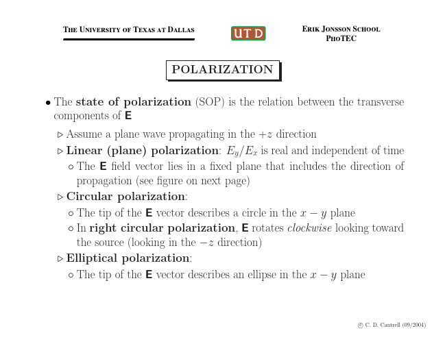
Ey = E2 cos(ωt − βz )
The University of Texas at Dallas
Erik Jonsson School PhoTEC
SNAPSHOT OF PLANE-POLARIZED PLANE WAVE
0
5
Z
10 15 1 0 X -1 0 -1 1
c C. D. Cantrell (03/2004)
2
2
The University of Texas at Dallas
Erik Jonsson School PhoTEC
ORTHOGONAL POLARIZATIONS (1) • For a plane wave, there are always 2 orthogonal states of polarization Simplest case: Orthogonal linear polarizations described by unit coordiˆ and y ˆ nate vectors x ˆ·y ˆ=0 ◦ Orthogonality: x ˆ·x ˆ=1=y ˆ·y ˆ ◦ Normalization: x ◦ Example of orthogonally polarized fields: ˆE1 cos(ωt − βz ), E1 = x ˆE2 cos(ωt − βz + δ ) E2 = y The important point: Waves with orthogonal polarizations do not interfere with one another • Example: In a “single-mode” fiber, there are really two modes, one for each of the two orthogonal polarizations These modes don’t have the same group velocity The difference in group velocities leads to polarization-mode dispersion, pulse spreading, and bandwidth limitations
冷原子光谱法 英语

冷原子光谱法英语Okay, here's a piece of writing on cold atom spectroscopy in an informal, conversational, and varied English style:Hey, you know what's fascinating? Cold atom spectroscopy! It's this crazy technique where you chill atoms down to near absolute zero and study their light emissions. It's like you're looking at the universe in a whole new way.Just imagine, you've got these tiny particles, frozen in place almost, and they're still putting out this beautiful light. It's kind of like looking at a fireworks display in a snow globe. The colors and patterns are incredible.The thing about cold atoms is that they're so slow-moving, it's easier to measure their properties. You can get really precise data on things like energy levels andtransitions. It's like having a super-high-resolution microscope for the quantum world.So, why do we bother with all this? Well, it turns out that cold atom spectroscopy has tons of applications. From building better sensors to understanding the fundamental laws of nature, it's a powerful tool. It's like having a key that unlocks secrets of the universe.And the coolest part? It's just so darn cool! I mean, chilling atoms to near absolute zero? That's crazy science fiction stuff, right?。
电感耦合等离子体原子发射光谱法的英文
电感耦合等离子体原子发射光谱法的英文全文共10篇示例,供读者参考篇1Title: The Magical World of Inductively Coupled Plasma Atomic Emission SpectroscopyHey guys, have you ever heard of inductively coupled plasma atomic emission spectroscopy? It's a super cool way to analyze the elements in different substances! Let's dive into the magical world of ICP-AES together!First off, what is inductively coupled plasma? Well, it's like a super hot gas that's created when we apply a high voltage to a gas like argon. This gas gets so hot that it turns into a plasma, which is a state of matter where the atoms are charged and can emit light when excited.Now, imagine we have a sample of a substance that we want to analyze. We inject this sample into the inductively coupled plasma, and the high temperature of the plasma breaks down the substance into its individual atoms. These atoms get excited by the heat and emit light at specific wavelengths.Next, we use a spectrometer to measure the intensity of the light emitted by the atoms. Each element emits light at different wavelengths, so by analyzing the light spectrum, we can identify which elements are present in the sample and how much of each element is there.ICP-AES is super useful in many fields like environmental science, pharmaceuticals, and even forensics. Scientists can use it to detect trace elements in water, analyze the composition of minerals, or even uncover evidence in criminal investigations.So, next time you hear about inductively coupled plasma atomic emission spectroscopy, remember that it's like magic that helps scientists unlock the secrets hidden in different substances. Cool, right? Science is amazing!篇2Title: Atomic Emission Spectroscopy Using Inductively Coupled PlasmaHey everyone! Today, we're going to talk about a super cool science technique called inductively coupled plasma atomic emission spectroscopy. It's a mouthful to say, but basically, it's a way to study the elements in different materials by using a super hot plasma.So, what's plasma? It's like a gas that's so hot that it turns into an electrically charged soup of ions and electrons. And when we zap it with a big electric current, it gets even hotter and emits light.In inductively coupled plasma atomic emission spectroscopy, we use this hot plasma to excite the atoms in a sample. Each element gives off light at a unique wavelength when it's excited, kind of like how each person has a unique fingerprint. By measuring the light emitted by the atoms, we can figure out which elements are present in the sample and how much of each element there is.This technique is super useful in chemistry and environmental science because it's really sensitive and can detect tiny amounts of elements in a sample. Plus, it's non-destructive, which means we don't have to destroy the sample to analyze it.So, next time you see a scientist using a big machine with a glowing plasma inside, you'll know they're probably using inductively coupled plasma atomic emission spectroscopy to learn more about the elements around us. Cool, right? Science is awesome!篇3Hey guys! Today I'm going to tell you all about this super cool thing called inductively coupled plasma atomic emission spectroscopy. Sounds like a mouthful, right? But don't worry, I'll break it down for you in simple terms.So basically, inductively coupled plasma atomic emission spectroscopy (ICP-AES for short) is a fancy way of analyzing the elements in a sample. It's like a science detective that can tell us what's inside something without even opening it up!Here's how it works: we take a small sample and turn it into a fine mist. Then we zap it with a super hot plasma made of ionized gas. This plasma is so hot that it turns the sample into ions and atoms, which give off light at different wavelengths. By measuring the intensity of this light, we can figure out what elements are in the sample.ICP-AES is really helpful in lots of different industries, like environmental testing, food safety, and even archaeology. It's like having a magic wand that can tell us all sorts of secrets about the world around us.So next time you hear about inductively coupled plasma atomic emission spectroscopy, remember that it's just a fancy way of saying we can use light to figure out what's in stuff. How cool is that?篇4Title: The Cool and Fun Plasma Atomic Emission Spectroscopy!Hey guys! Today I want to talk to you about something super cool and fun - it's called inductively coupled plasma atomic emission spectroscopy (ICP-AES). Sounds like a mouthful, right? But don't worry, I'll break it down for you in a way that's easy to understand.So, what is ICP-AES? Basically, it's a fancy science technique that scientists use to analyze the elements present in a sample. They do this by zapping the sample with a super hot plasma (like the sun's surface!) and then measuring the light that gets emitted. Each element in the sample emits a unique pattern of light, kind of like a fingerprint, and scientists can use this pattern to figure out what elements are in the sample.The cool thing about ICP-AES is that it's really sensitive - it can detect even tiny amounts of elements in a sample. That's why scientists use it in all sorts of fields, like environmental science, food safety, and even forensics!And the best part? You can do your own mini version of ICP-AES at home! Just grab a flashlight and shine it on differentobjects in your house. Notice how some objects reflect the light differently? That's kind of like how elements emit light inICP-AES.So next time you see a cool science experiment or hear about ICP-AES, remember how fun and fascinating it can be! Who knows, maybe one day you'll become a super cool scientist using ICP-AES to make important discoveries. The sky's the limit!篇5Oh, hi there! Today I want to talk to you about something super cool called inductively coupled plasma atomic emission spectroscopy. It's a mouthful, I know, but it's really awesome.So, basically, inductively coupled plasma atomic emission spectroscopy is a method used to analyze the elements in a sample. It works by using a high temperature plasma to break down the sample into its individual atoms, which then emit light at specific wavelengths.This light is then detected and analyzed to determine the elements present in the sample. It's kind of like a fingerprint for each element, and scientists can use this information to identify and quantify the elements in a sample.ICP-AES is used in a lot of different fields, like environmental testing, food safety, and even crime scene investigation. It's super important because it allows scientists to accurately and quickly analyze the composition of samples without destroying them.So there you have it, inductively coupled plasma atomic emission spectroscopy in a nutshell. It's a really cool technique that helps scientists understand the world around us better. Pretty neat, huh?篇6Hey guys! Today I'm going to tell you all about this really cool science thing called inductively coupled plasma atomic emission spectrometry. Wow, that's a big phrase! But don't worry, I'll break it down for you.So basically, inductively coupled plasma is like a super hot gas that can reach temperatures of up to 10,000 degrees Celsius – that's hotter than the sun! When we use this plasma to excite atoms in a sample, it causes them to emit light at specific wavelengths. This is what we call atomic emission spectroscopy.This technique is super useful because it allows scientists to analyze the elements present in a sample by measuring theintensity of the emitted light. It's used in all sorts of things like testing water for pollutants, checking the quality of metals, and even analyzing rocks from outer space!Isn't that amazing? We can learn so much about the world around us just by looking at the light emitted by atoms. And it's all thanks to inductively coupled plasma atomic emission spectrometry – what a mouthful!So next time you see a bright light in a science lab, you'll know that it's not just any light – it's the light of knowledge shining bright through the world of atomic emission spectroscopy. Cool, right? Keep on exploring, little scientists!篇7Title: The Cool Plasma Science Experiment!Hey there everyone! Today, we're going to talk about something super cool - the Inductively Coupled Plasma Atomic Emission Spectroscopy! Doesn't that sound fancy? But don't worry, I'll explain it in simple words.So, in this experiment, we use something called a plasma to see what elements are in a sample. Now, plasma is like a superhot gas that can turn things into ions. It's like a superhero for scientists!We start by putting the sample into the plasma. The plasma is made using electricity and gas, and it gets super hot - like as hot as the sun! This heat turns the sample into ions and atoms, and they give off light. This light is called emission, and it has different colors depending on which element is in the sample.We use a special instrument called a spectrometer to see the different colors of light. The spectrometer separates the light into different colors like a rainbow and helps us figure out which elements are in the sample.It's a really cool experiment because we can find out what things are made of without even touching them! Scientists use this technique to study things like rocks, metals, and even blood!So, next time you see a rainbow, remember that scientists are using a similar technique to figure out what's in our world. Isn't science amazing?篇8Title: Exciting Plasma: Learning About Atomic Emission Spectroscopy with Inductively Coupled PlasmaHey everyone, do you know that scientists have a super cool way to study atoms and figure out what elements are in different things? It's called Inductively Coupled Plasma Atomic Emission Spectroscopy, or ICP-AES for short.So, what is ICP-AES all about? Well, first we need to know what is plasma. Plasma is like a super hot gas that has electrons and ions flying around. When we use electricity to heat up a gas, it turns into plasma. And that's where the magic happens!In ICP-AES, we use a machine that creates plasma by using radio frequency electricity. The plasma is so hot that it can burn anything that comes near it! When we put a sample into the plasma, the atoms in the sample get super excited and jump around. And when they cool down, they release light in different colors.By looking at the colors of the light, scientists can figure out what elements are in the sample. Each element gives off a different color of light, like a fingerprint. So cool, right?ICP-AES is super important in chemistry and other fields because it helps us identify elements in things like soil, water, and even our bodies! Scientists use it to make sure our food is safe to eat, check for pollutants in the environment, and so much more.So next time you hear about ICP-AES, remember that it's all about creating exciting plasma to learn about the tiny atoms that make up everything around us. It's like a superpower that helps scientists solve mysteries at the tiniest level. How awesome is that?篇9Hey guys! Today I'm gonna talk to you about something super cool - the Inductively Coupled Plasma-Atomic Emission Spectroscopy. It's a mouthful, I know, but it's really interesting!So, this fancy-sounding technique is used to analyze the elements present in different samples. It works by using a plasma torch to heat up the sample, turning it into a gas. This gas is then excited by radiofrequency energy and an oscillating magnetic field, creating a plasma that emits light.The light emitted by the plasma is then analyzed to determine the elements present in the sample. Each element emits a unique set of wavelengths of light, which are captured by a spectrometer. By analyzing these wavelengths, scientists can identify the elements in the sample and measure their concentrations.ICP-AES is commonly used in environmental analysis, food and beverage testing, and material analysis. It is a sensitive and efficient technique that can analyze multiple elements at once, making it a valuable tool in scientific research.So there you have it, a simplified explanation of the Inductively Coupled Plasma-Atomic Emission Spectroscopy. Who knew science could be so cool, right? Keep learning and exploring, you never know what amazing discoveries you might make!篇10Electric Induction Coupled Plasma Atomic Emission Spectroscopy is a very fancy name for a super cool science experiment that helps scientists learn more about different elements. This special machine can detect tiny amounts of elements in all kinds of different materials, like rocks, food, and even our bodies!So how does this machine work? Well, first, scientists put a small sample of the material they want to study into the machine. Then, they use electricity to heat up the sample until it turns into something called a plasma. Now, don't worry, plasma isn't likethe plasma in your blood, it's actually a super hot gas that can give off light.Once the sample is in plasma form, the machine uses a special tool called a spectroscope to analyze the different colors of light that the sample gives off. Each element gives off its own unique colors of light, kind of like a fingerprint. By looking at these colors, scientists can figure out what elements are in the sample and how much of each one is present.This technology is super important because it helps scientists figure out what things are made of and can even help them solve all kinds of mysteries, like what materials were used to make ancient artifacts or where pollutants are coming from.So next time you hear about Electric Induction Coupled Plasma Atomic Emission Spectroscopy, remember that it's just a fancy way of saying that scientists are using cool machines to learn more about the world around us!。
中科院博士研究生英语精读教材翻译及原文整理解读

第1课知识的悖论The Paradox of KnowledgeThe greatest achievement of humankind in its long evolution from ancient hominoid ancestors to its present status is the acquisition and accumulation of a vast body of knowledge about itself, the world, and the universe. The products of this knowledge are all those things that, in the aggregate, we call "civilization," including language, science, literature, art, all the physical mechanisms, instruments, and structures we use, and the physical infrastructures on which society relies. Most of us assume that in modern society knowledge of all kinds is continually increasing and the aggregation of new information into the corpus of our social or collective knowledge is steadily reducing the area of ignorance about ourselves, the world, and the universe. But continuing reminders of the numerous areas of our present ignorance invite a critical analysis of this assumption.In the popular view, intellectual evolution is similar to, although much more rapid than, somatic evolution. Biological evolution is often described by the statement that "ontogeny recapitulates phylogeny"--meaning that the individual embryo, in its development from a fertilized ovum into a human baby, passes through successive stages in which it resembles ancestral forms of the human species. The popular view is that humankind has progressed from a state of innocent ignorance, comparable to that of an infant, and gradually has acquired more and more knowledge, much as a child learns in passing through the several grades of the educational system. Implicit in this view is an assumption that phylogeny resembles ontogeny, so that there will ultimately be a stage in which the accumulation of knowledge is essentially complete, at least in specific fields, as if society had graduated with all the advanced degrees that signify mastery of important subjects.Such views have, in fact, been expressed by some eminent scientists. In 1894 the great American physicist Albert Michelson said in a talk at the University of Chicago:While it is never safe to affirm that the future of Physical Science has no marvels in store even more astonishing than those of the past, it seems probable that most of the grand underlying principles have been firmly established and that further advances are to be sought chiefly in the rigorous application of these principles to all the phenomena which come under our notice .... The future truths of Physical Science ate to be looked for in the sixth place of decimals.In the century since Michelson's talk, scientists have discovered much more than the refinement of measurements in the sixth decimal place, and none is willing to make a similar statement today. However, many still cling to the notion that such a state of knowledge remains a possibility to be attained sooner or later. Stephen Hawking, thegreat English scientist, in his immensely popular book A Brief History of Time (1988), concludes with the speculation that we may "discover a complete theory" that "would be the ultimate triumph of human reason--for then we would know the mind of God." Paul Davies, an Australian physicist, echoes that view by suggesting that the human mind may be able to grasp some of the secrets encompassed by the title of his book The Mind of God (1992). Other contemporary scientists write of "theories of everything," meaning theories that explain all observable physical phenomena, and Nobel Laureate Steven Weinberg, one of the founders of the current standard model of physical theory, writes of his Dreams of a Final Theory (1992).Despite the eminence and obvious yearning of these and many other contemporary scientists, there is nothing in the history of science to suggest that any addition of data or theories to the body of scientific knowledge will ever provide answers to all questions in any field. On the contrary, the history of science indicates that increasing knowledge brings awareness of new areas of ignorance and of new questions to be answered.Astronomy is the most ancient of the sciences, and its development is a model of other fields of knowledge. People have been observing the stars and other celestial bodies since the dawn of recorded history. As early as 3000 B.C. the Babylonians recognized a number of the constellations. In the sixth century B.C., Pythagoras proposed the notion of a spherical Earth and of a universe with objects in it chat moved in accordance with natural laws. Later Greek philosophers taught that the sky was a hollow globe surrounding the Earth, that it was supported on an axis running through the Earth, and chat stars were inlaid on its inner surface, which rotated westward daily. In the second century A.D., Ptolemy propounded a theory of a geocentric (Earth-centered) universe in which the sun, planets, and stars moved in circular orbits of cycles and epicycles around the Earth, although the Earth was not at the precise center of these orbits. While somewhat awkward, the Ptolemaic system could produce reasonably reliable predictions of planetary positions, which were, however, good for only a few years and which developed substantial discrepancies from actual observations over a long period of time. Nevertheless, since there was no evidence then apparent to astronomers that the Earth itself moves, the Ptolemaic system remained unchallenged for more than 13 centuries.In the sixteenth century Nocolaus Copernicus, who is said to have mastered all the knowledge of his day in mathematics, astronomy, medicine, and theology, became dissatisfied with the Ptolemaic system. He found that a heliocentric system was both mathematically possible and aesthetically more pleasing, and wrote a full exposition of his hypothesis, which was not published until 1543, shortly after his death. Early inthe seventeenth century, Johannes Kepler became imperial mathematician of the Holy Roman Empire upon the death of Tycho Brahe, and he acquired a collection of meticulous naked-eye observations of the positions of celestial bodies chat had been made by Brahe. On the basis of these data, Kepler calculated that both Ptolemy and Copernicus were in error in assuming chat planets traveled in circular orbits, and in 1609 he published a book demonstrating mathematically chat the planets travel around the sun in elliptical orbits. Kepler's laws of planetary motion are still regarded as basically valid.In the first decade of the seventeenth century Galileo Galilei learned of the invention of the telescope and began to build such instruments, becoming the first person to use a telescope for astronomical observations, and thus discovering craters on the moon, phases of Venus, and the satellites of Jupiter. His observations convinced him of the validity of the Copernican system and resulted in the well-known conflict between Galileo and church authorities. In January 1642 Galileo died, and in December of chat year Isaac Newton was born. Modern science derives largely from the work of these two men.Newton's contributions to science are numerous. He laid the foundations for modem physical optics, formulated the basic laws of motion and the law of universal gravitation, and devised the infinitesimal calculus. Newton's laws of motion and gravitation are still used for calculations of such matters as trajectories of spacecraft and satellites and orbits of planets. In 1846, relying on such calculations as a guide to observation, astronomers discovered the planet Neptune.While calculations based on Newton's laws are accurate, they are dismayingly complex when three or more bodies are involved. In 1915, Einstein announced his theory of general relativity, which led to a set of differential equations for planetary orbits identical to those based on Newtonian calculations, except for those relating to the planet Mercury. The elliptical orbit of Mercury rotates through the years, but so slowly that the change of position is less than one minute of arc each century. The equations of general relativity precisely accounted for this precession; Newtonian equations did not.Einstein's equations also explained the red shift in the light from distant stars and the deflection of starlight as it passed near the sun. However, Einstein assumed chat the universe was static, and, in order to permit a meaningful solution to the equations of relativity, in 1917 he added another term, called a "cosmological constant," to the equations. Although the existence and significance of a cosmological constant is still being debated, Einstein later declared chat this was a major mistake, as Edwin Hubble established in the 1920s chat the universe is expanding and galaxies are receding fromone another at a speed proportionate to their distance.Another important development in astronomy grew out of Newton's experimentation in optics, beginning with his demonstration chat sunlight could be broken up by a prism into a spectrum of different colors, which led to the science of spectroscopy. In the twentieth century, spectroscopy was applied to astronomy to gun information about the chemical and physical condition of celestial bodies chat was not disclosed by visual observation. In the 1920s, precise photographic photometry was introduced to astronomy and quantitative spectrochemical analysis became common. Also during the 1920s, scientists like Heisenberg, de Broglie, Schrodinger, and Dirac developed quantum mechanics, a branch of physics dealing with subatomic particles of matter and quanta of energy. Astronomers began to recognize that the properties of celestial bodies, including planets, could be well understood only in terms of physics, and the field began to be referred to as "astrophysics."These developments created an explosive expansion in our knowledge of astronomy. During the first five thousand years or more of observing the heavens, observation was confined to the narrow band of visible light. In the last half of this century astronomical observations have been made across the spectrum of electromagnetic radiation, including radio waves, infrared, ultraviolet, X-rays, and gamma rays, and from satellites beyond the atmosphere. It is no exaggeration to say chat since the end of World War II more astronomical data have been gathered than during all of the thousands of years of preceding human history.However, despite all improvements in instrumentation, increasing sophistication of analysis and calculation augmented by the massive power of computers, and the huge aggregation of data, or knowledge, we still cannot predict future movements of planets and other elements of even the solar system with a high degree of certainty. Ivars Peterson, a highly trained science writer and an editor of Science News, writes in his book Newton's Clock (1993) that a surprisingly subtle chaos pervades the solar system. He states:In one way or another the problem of the solar system's stability has fascinated and tormented asrtonomers and mathematicians for more than 200 years. Somewhat to the embarrassment of contemporary experts, it remains one of the most perplexing, unsolved issues in celestial mechanics. Each step toward resolving this and related questions has only exposed additional uncertainties and even deeper mysteries.Similar problems pervade astronomy. The two major theories of cosmology, general relativity and quantum mechanics, cannot be stated in the same mathematical language, and thus are inconsistent with one another, as the Ptolemaic and Copernicantheories were in the sixteenth century, although both contemporary theories continue to be used, but for different calculations. Oxford mathematician Roger Penrose, in The Emperors New Mind (1989), contends that this inconsistency requires a change in quantum theory to provide a new theory he calls "correct quantum gravity."Furthermore, the observations astronomers make with new technologies disclose a total mass in the universe that is less than about 10 percent of the total mass that mathematical calculations require the universe to contain on the basis of its observed rate of expansion. If the universe contains no more mass than we have been able to observe directly, then according to all current theories it should have expanded in the past, and be expanding now, much more rapidly than the rate actually observed. It is therefore believed that 90 percent or more of the mass in the universe is some sort of "dark matter" that has not yet been observed and the nature of which is unknown. Current theories favor either WIMPs (weakly interacting massive particles) or MACHOs (massive compact halo objects). Other similar mysteries abound and increase in number as our ability to observe improves.The progress of biological and life sciences has been similar to that of the physical sciences, except that it has occurred several centuries later. The theory of biological evolution first came to the attention of scientists with the publication of Darwin's Origin of Species in 1859. But Darwin lacked any explanation of the causes of variation and inheritance of characteristics. These were provided by Gregor Mendel, who laid the mathematical foundation of genetics with the publication of papers in 1865 and 1866.Medicine, according to Lewis Thomas, is the youngest science, having become truly scientific only in the 1930s. Recent and ongoing research has created uncertainty about even such basic concepts as when and how life begins and when death occurs, and we are spending billions in an attempt to learn how much it may be possible to know about human genetics. Modern medicine has demonstrably improved both our life expectancies and our health, and further improvements continue to be made as research progresses. But new questions arise even more rapidly than our research resources grow, as the host of problems related to the Human Genome Project illustrates.From even such an abbreviated and incomplete survey of science as this, it appears that increasing knowledge does not result in a commensurate decrease in ignorance, but, on the contrary, exposes new lacunae in our comprehension and confronts us with unforeseen questions disclosing areas of ignorance of which we were not previously aware.Thus the concept of science as an expanding body of knowledge that will eventually encompass or dispel all significant areas of ignorance is an illusion. Scientists and philosophers are now observing that it is naive to regard science as a process that begins with observations that are organized into theories and are then subsequently tested by experiments. The late Karl Popper, a leading philosopher of science, wrote in The Growth of Scientific Knowledge (1960) chat science starts from problems, not from observations, and chat every worthwhile new theory raises new problems. Thus there is no danger that science will come to an end because it has completed its task, clanks to the "infinity of our ignorance."At least since Thomas Kuhn published The Structure of Scientific Revolutions (1962), it has been generally recognized that observations are the result of theories (called paradigms by Kuhn and other philosophers), for without theories of relevance and irrelevance there would be no basis for determining what observations to make. Since no one can know everything, to be fully informed on any subject (a claim sometimes made by those in authority) is simply to reach a judgment that additional data are not important enough to be worth the trouble of securing or considering.To carry the analysis another step, it must be recognized that theories are the result of questions and questions are the product of perceived ignorance. Thus it is chat ignorance gives rise to inquiry chat produces knowledge, which, in turn, discloses new areas of ignorance. This is the paradox of knowledge: As knowledge increases so does ignorance, and ignorance may increase more than its related knowledge.My own metaphor to illustrate the relationship of knowledge and ignorance is based on a line from Matthew Arnold: "For we are here as on a darkling plain...." The dark chat surrounds us, chat, indeed, envelops our world, is ignorance. Knowledge is the illumination shed by whatever candles (or more technologically advanced light sources) we can provide. As we light more and more figurative candles, the area of illumination enlarges; but the area beyond illumination increases geometrically. We know chat there is much we don't know; but we cannot know how much there is chat we don't know. Thus knowledge is finite, but ignorance is infinite, and the finite cannot ever encompass the infinite.This is a revised version of an article originally published in COSMOS 1994. Copyright 1995 by Lee Loevinger.Lee Loevinger is a Washington lawyer and former assistant attorney general of the United States who writes frequently for scientific c publications. He has participated for many years as a member, co-chair, or liaison with the National Conference of Lawyers and Scientists, and he is a founder and former chair of the Science andTechnology Section of the American Bar Association. Office address: Hogan and Hartson, 555 Thirteenth St. NW, Washington, DC 20004.人类从古类人猿进化到当前的状态这个长久的进化过程中的最大成就是有关于人类自身、世界以及宇宙众多知识的获得和积聚。
傅里叶红外测试英语
傅里叶红外测试英语Fourier Infrared SpectroscopyIntroductionFourier infrared spectroscopy, or FIAS, is a scientific tool used to study the properties of molecules. It is particularly useful because of its ability to provide detailed information about a molecule’s fundamental molecular structure.The Fourier transform is an important mathematical technique which converts a set of data points into a mathematical representation that can be used to analyse and interpret it. The Fourier transform is used in a variety of fields, from signal processing to image processing, and its application to infrared spectroscopy enables researchers to analyse the energy distribution of a molecule’s infrared spectrum.In Fourier infrared spectroscopy, the molecule is subjected to an electromagnetic energy source, usually light, which is analysed in terms of its frequency. The energy from the source is broken into discrete frequencies, and each frequency is used to observe the infrared spectrum of the molecule. This spectrum can then be used to determine themolecular structure of the molecule, as well as its vibrational and rotational energies.TechniqueFIAS is a relatively simple technique, as it involves the use of a standard Fourier transform algorithm. The algorithm breaks the energy source into discrete frequencies, which are then used to calculate the molecule's infrared spectrum. From this spectrum, the molecular structure of the molecule can be determined.The data from the Fourier transform can be used to calculate a variety of parameters, such as the wavelength of the energy source, the intensity of the energy at each frequency, and the molecular structure of the molecule. It is possible to measure the vibrational and rotational energy of a molecule as well, by combining the frequencies of several different energy sources.In addition to providing information about the fundamental molecular structure, FIAS can also be used to measure the concentration of certain molecules in a sample. This can be done by using a source of energy which is specific to the molecule being studied.ApplicationsFIAS is used in many areas of scientific research, including biochemistry and materials science. In biochemistry, FIAS is used to analyse the structure of proteins, lipids, and carbohydrates. In materials science, it is used to analyse the structure of polymers and other materials.FIAS is also used in drug discovery, as it allows researchers to analyse the structure of a molecule and determine how it interacts with other molecules. This type of analysis can help researchers identify potential therapeutic compounds and drug candidates.ConclusionFIAS is a powerful tool that can provide detailed information about the properties of molecules. It is used in many areas of scientific research, from biochemistry to drug discovery. By analysing the energy distribution of a molecule’s infrared spectrum, researchers are able to calculate its molecular structure and determine its vibrational and rotational energies. The data from the Fourier transform can also be used to measure the concentration of certain molecules.。
fluorescence polarization
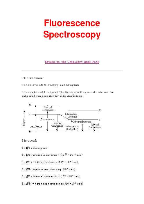
FluorescenceSpectroscopyReturn to the Chemistry Home PageFluorescenceSchematic state energy level diagramS is singlet and T is triplet. The S0 state is the ground state and the subscript numbers identify individual states.TimescaleS0∅ S n absorptionS n∅ S1 internal conversion (10-11 - 10-14 sec)S1∅ S0 + hν fluorescence (10-7 - 10-9 sec)S1∅ T n intersystem crossing (10-8 sec)S1∅ S0 internal conversion (10-5 - 10-7 sec)T1∅ S0 + hν phosphorescence (10 - 10-3 sec)T1∅ S0 internal conversion (10 - 10-3 sec)Characteristics of Excited States1.Energy2.Lifetime3.Quantum Yield4.PolarizationPhosphorescence occurs at longer wavelength than does fluorescenceOften, the emission band is red-shifted relative to the absorption band: "Stokes shift"Excited states decay exponentially with timeI = I0e-t/τI0 is the initial intensity at time zero,I is the intensity at some later time t,and τ is the lifetime of the excited state.Also, k F = 1/ τ, where k F is the rate constant for fluorescence.Quantum Yield = ΦΦF = number of fluorescence quanta emitted divided by number of quanta absorbed to a singlet excited stateΦF = ratio of photons emitted to photons absorbedQuantum yield is the ratio of photons emitted to photons absorbed by the system: ΦF = k F / k F + k ISC + k nr + k q + k rPolarizationMolecule of interest is randomly oriented in a rigid matrix (organic solvent at low temperature or room temperature polymer). Plane polarized light is used as the excitation source.The degree of polarization is defined as follows:where I|| and I⊥ are the intensities of the observed parallel and perpendicular components, respectively. α is the angle between the emission and absorption transition moments. If α is 0° than P = +1/2, and if α is 90° than P = -1/3.Figure 26, Becker, pg. 84Polarization of fluorescence of phenol in propylene glycol at -70°C shows that the transition moments of the corresponding absorption bands are mutually perpendicular.Phosphorescence is usually slow (seconds) therefore quenching by impurities including oxygen usually makes phosphorescence difficult to observe. Low temperature glasses and rigorous exclusion of oxygen is usually necessary to observe phosphorescence. Since this condition is not biological, fluorescence is the primary emission process of biological relevance.Experimental MeasurementsSteady-state measurements: Φ, ITime-Resolved measurements: τEmission spectra are obtained when the excitation monochrometer M1 is fixed and the emission monochrometer M2 is scanned.If M2 is fixed and M1 is scanned the result is an excitation spectrum. Excitation and absorption spectra should be identical.Relative quantum yields are determined by using a standard such as quinine sulfate in 1 N H2SO4 (φF = 0.70), or fluorescein in 0.1 N NaOH (φF = 0.93). The areas under the emission band of the standard relative to the sample are compared. It is of course important that the absorption at λex are matched.Excited-state decay rates can be measured by exciting the sample with a short pulse of light and monitoring the emission as a function of time.Figure 8-14, Cantor & Schimmel, pg. 442. Fluorescence decay of a pure sample showing a single exponential decay. The dark line shows the excitation pulse. Time correlated single photon counting was used to obtain this data. This technique counts the number of emitted photons hitting a detector at times, t, following excitationOne critical difference between steady-state and kinetic measurements of fluorescence is that the value of τF is not a function of concentration of the sample while the value of ΦF is concentration dependent. Only at low concentration is the value of ΦF linearly dependent on concentration. The reason is the so-called inner filter effect.The inner filter effect:At low concentration the emission of light is uniform from the front to the back of sample cuvette. At high concentration more light is emitted from the front than the back. Since emitted light only from the middle of the cuvette is detected the concentration must be low to assure accurate ΦF measurements.Fluorescence characteristics of chromophores found in proteins and nucleic acids. Generally, quantum yields are low and lifetimes are short.Absorption Fluorescence SensitivitySubstance Condition λmax(nm) εmax10-3λmax(nm)φFτF(nsec)εmaxφF10-2Tryptophan H2O, pH 7 280 5.6 348 0.20 2.6 11 Tyrosine H2O, pH 7 274 1.4 303 0.14 3.6 2.0 Phenylalanine H2O, pH 7 257 0.2 282 0.04 6.4 0.08 Adenine H2O, pH 7 260 13.4 321 2.6 10-4<0.02 0.032Guanine H2O, pH 7 275 8.1 329 2.610-4<0.02 0.024Cytosine H2O, pH 7 267 6.1 313 0.810-4<0.02 0.005Uracil H2O, pH 7 260 9.5 308 0.410-4<0.02 0.004 NADH H2O, pH 7 340 6.2 470 0.019 0.40 1.2Figure 8-15, Cantor & Schimmel, pg. 444 Fluorescence emission spectra of human serum albumin (solid line), tryptophan alone (dashed line), and an 18:1 molar ratio of tyrosine to tryptophan (gray line): Excitation at 245 nm.The 18:1 sample approximates the relative occurrence of these amino acids in the protein. Note that the spectrum of the protein closelyresembles that of pure tryptophan because tyrosine sensitivity is low and its emission is most likely quenched by tryptophan (viaenergy-transfer mechanism).Commonly, fluorescent probe molecules are used to characterize protein and nucleic acids.Sensitivity is higher.max is also different from biomolecule so selective excitation is possible.Fluorescence generally is much more sensitive to the environment of the chromophore than is light absorption. Therefore, fluorescence is an effective technique for following the binding of ligands or conformational changes.The sensitivity of fluorescence is a consequence of the relatively long time a molecule stays in an excited singlet state before deexcitation. Absorption, or CD, is a process that is over in 10-15 sec. On this time scale, the molecule and its environment are effectively static. In contrast, during the 10-9 to 10-8 sec that a singlet remains excited, all kinds of processes can occur, including protonation or deprotonation reactions, solvent-cage relaxation, local conformational changes, and any processes coupled to translational or rotational motion.A number of fluorescent molecules have a very convenient propertyin aqueous solution their fluorescence is very strongly quenched, but in a nonpolar or a rigid environment (like in a protein or nucleic acid) a striking enhancement is observed.Figure 8-17, Cantor & Schimmel, pg. 447.In addition protein protects the probe from quenchers such as oxygen. F0/F = φo/φ = [k F + k IC + k ISC + k q(Q)]/(k F + k IC + k ISC) = 1 + k qτ0(Q),where F = fluorescence in the presence of quencher, F0 = fluorescence in the absence of quencher.Therefore a plot of F0/F versus concentration of Q will yield a value for k q. Quenching of tryptophan fluorescence by collision with oxygen: Tryptophan: k q = 12 109 M-1 sec-1 (diffusion controlled)Carbonic anhydrase: k q = 2.6 109 M-1 sec-1Singlet-Singlet Energy TransferIf the emission band of a molecule (D) coincides with the absorption band of another (A) two processes occur: emission of D is quenched, emission of A is sensitized.Figure 8-18, Cantor & Schimmel, pg. 449Förster theory can be used to determine distance between chromophoresThe rate of energy transfer = k T = (1/τD)(R0/R)-6.τD = lifetime of D in the absence of A.R0 = characteristic transfer distance = 9.7 103 (J κ2 n-4φD)1/6 cm, where J =∨εA(ν)f D(ν)ν-4 dvJ is a measure of the spectral overlap between donor emission and acceptor absorption (shaded region in figure). F D is the normalized fluorescence of the donor; n is the refractive index of the mediumbetween donor and acceptor; φD is the quantum yield of donor in the absence of acceptor; and κ2 is a complex geometric factor that depends on the orientation of donor and acceptor. If both donor and acceptor are free to tumble rapidly on the time scale of fluorescence emission, κ2 approaches a limiting value of 2/3.If the efficiency of energy transfer is expressed as E = k T/(k T + 1/τD) than E = R06/(R06 + R6).Figure 8-20, Cantor & Schimmel, pg. 455For dansyl-(L-proline)n-α-naphthyl for n = 1 to 12. For this pair R0 = 50Å. Energy transfer plays a large role in determining the emission spectrum of normal proteins.The fluorescence of tyrosine is overlapped by the absorption of tryptophan. The R0 for this donor-acceptor pair is about 9 Å. This is short enough, given the average size of globular proteins, such that most tyrosines in proteins are quenched by singlet-singlet energy transfer by tryptophan.The result is that observed emission comes from primarily tryptophan (see above).Fluorescence Anisotropy/PolarizationFigure 16-14 and legend, pg. 529, MarchellSteady-state experimentcontinuous irradiation with polarized light of molecules in solution.Polarization =I|| and I⊥ are time-independent steady state values for fluorescent intensity polarized parallel and perpendicular.P o is the maximum P which occurs when the rotational motion is very slow compared to the singlet excited state lifetime.τrot = rotational correlation time = the characteristic lifetime of rotational diffusion. For large proteins τrot is large.If τrot << τF than the polarization, P, approaches zero (i.e., the steady-state fluorescence is completely depolarized so that by the time the fluorescence occurs, the direction of oscillation of the emission dipole is completely random).The relationship between P and τrot is:τrot is related to the rotational diffusion constant, D rot, according to:η = solution viscosityk, R = gas constant per molecule and per mole, respectivelyr = molecular radius for spherical moleculeV = 4/3 πr3N o = molar volumeT = temperature in °KTherefore:This is the Perrin EquationIf the temperature, T, is low or the viscosity, η, is large, than T/ηapproaches zero and molecular motion will be slowed down to the limit τrot >> τF and the polarization, P, reaches its maximum value, P o.The slope of the plot of versus will be which yields a value for V since τF is known. This in turn yields a value for τrot and an estimate for the radius of the molecule (note: these equations are valid only for spherical molecules).Perrin plot for human macroglobulin (MW = 900,000 Da) and two fragments (MW = 180,000 and 50,000 Da) yields values for τrot.The protein is first covalently labeled with dansyl chloride which has strong fluorescence when bound to proteins and a τF = 12 ns.900 kDa => τrot = 80 ns180 kDa => τrot = 69 ns50 kDa => τrot = 58 nsIf the 50 kDa and 900 kDa were both rigid molecules one would expect a 260% reduction in τrot, but only get 25% reduction. Therefore, the 900 kDa protein must be highly flexible.Time-resolved Fluorescence Depolarization (Anisotropy).A short pulse of vertically polarized light is directed at the sample;the light is absorbed, promoting the molecule to an excited singlet state; following vibrational relaxation, light is emitted (fluorescence) at lower energy;if the molecule rotates during the time interval between absorption and emission, there will be a decrease in the polarization with time at a rate that reflects the rate at which the molecule rotates diffusionally.Fluorescence Anisotropy =at times, t, after the light pulse is turned off.The overall fluorescent intensity [I|||(t) + 2I⊥(t)] will decrease exponentially in time according to the lifetime, τF, of the excited singlet state.The A(t) will decrease with a time constant, τrot, which represents the time it takes for a molecule to rotate diffusionally, i.e., A(t) = A o exp(-t/τrot).A dansyl-labeled protein can be used to determine directly the τrot in a time-resolved experiment.Figure 16-15, pg. 532, Marshell(a) dansyl-labeled protein in membrane(b) free dansyl-labeled proteinA(t) is bi-exponential, i.e., two τrot’s.In (a) τrot A = 3 ns, τrot B = 700 ns.In (b) τrot A = 3 ns, τrot B = 45 ns.The fast component is due to local flexibility at the site of attachment of the label to the protein, and the slow component corresponds to rotational diffusion of the whole protein molecule.Clearly, in a membrane the protein is highly immobilized.Rotational Correlation Times, τrot, of Proteins, Determined Either from Experimentally Measured Fluorescence Depolarization Decay Rates or from Theoretical Models of the Protein as a Sphere in a Continuous Medium.Fluorescence depolarization studies of an antibody to which a fluorescent hapten was bound provided evidence for internal flexibility in the immunoglobulin molecule.Antibodies were grown specific to a dansyl-hapten.Depolarization studies of the hapten-antibody complex reveals two τrot’s ( 33 and 168 ns).The fast component may be due to flexibility in the "hinge" region that joins the fragments and the slow component is most likely due to rotation of the whole complex.Fluorescence Polarization (FP)—Note 1.4Share |Principles∙∙Fluorescence polar ization measurements provide information on molecular orientation and mobility and processes that modulate them, including r eceptor–ligand interactions, protein–DNA interactions, proteolysis, membrane fluidity and muscle contraction (Figure 1).Because polarization is a general property of fluorescent molecules (w ith certain exceptions such as lanthanide chelates), polarization-based readouts are somew hat less dye dependent and l ess susceptible to environmental interferences such as pH changes than assays based on fluorescence intensity measurements.E x perimentally, the degree of polar ization is deter mined from measurements of fluorescence intensities parallel and per pendicular w ith respect to the plane of linearly polarized excitation light, and is expressed in ter ms of fluorescence polarization (P) or anisotropy (r):Note that both P and r are ratio quantities w ith no nominal dependence on dye concentration. Because of the ratio for mulation, fluorescence intensity variations due to the presence of colored sample additives tend tocancel and produce relatively minor inteferences.P has physically possible values ranging from –0.33 to 0.5. In practice, these limiting values ar e rarely attained. Measured values of P in bioanalytical applications typically range from 0.01 to 0.3 or 10 to 300 mP (mP = P/1000). This measurement range is not as narrow as it might appear to be because very precise measurements (P ± 0.002 or ± 2 mP) are readily obtainable w ith modern instrumentation.Figure 1.Physical bas is of fluorescence polarization assays. Dye molecules w ith their absorption transition vectors (arrows) aligned parallel to the electric vector of linearly polar ized light (along the vertical page axis) are selectively excited. For dyes attach ed to s mall, rapidly rotating molecules, the initially photoselected orientational distribution becomes randomized prior to emission, resulting in low fluorescence polar ization. Conversely, binding of the low molecular w eight tracer to a large, s low ly rotating molecule results in high fluorescence polar ization. Fluorescence polarization therefore prov ides a direct readout of the extent of tracer binding to proteins, nucleic acids and other biopoly mers.Dependence of Fluorescence Polarization onMolecular Mobility∙∙Interpretation of the dependence of fluorescence polarization on molecular mobility is usually based on a modelderived in 1926 from the physical theory of Brow nian motion by P errin.where P o is the fundamental polarization of the dye (for fluorescein, rhodamine and BODIP Y dyes, P o is close to the theoretical maximum of 0.5), τ is the excited-state lifetime o f the dye and φ is the rotational correlation time of the dye or dye conjugate. These r elationships can be expressed in ter ms of fluorescence anisotropy in an equivalent and mathematically simpler manner. For a hydrodynamic sphere, φ can be estimated as fo llows:where η = solvent v iscosity, T = temperature, R = gas constant and V = mo lecular volume of the fluorescent dye or dye conjugate. In turn, V can be estimated from the molecular w eight of the dye or dye conjugate w ith appropr iate adjustments for hydration. Simulations of these relationships are show n in Figure 2., leading to the follow ing gener al conclusions:∙Fluorescence polarization increases as molecular w eight increases.∙Fluorescence polarization increases as solvent viscosity increases.∙Fluorescence polarization decreases as the excited state lifetime of the dye (τ) increas es.Note that these simulations assume that the dye is rigidly attached to a spher ical carrier. When conventional parameter estimates for proteins in aqueous solutions are used, φ is found to increase by about 1 ns per 2400dalton increase of molecular weight.Figure 2.Simulation of the relationship betw eenmolecular w eight (MW) and fluorescence polar ization(P). Simulations are show n for dyes w ith variousfluorescence lifetimes (τ): 1 ns (cyanine dyes) inpurple, 4 ns (fluorescein and Alexa Fluor 488 dyes) inred, 6 ns (some BODIP Y dyes) in green and 20 ns(dansyl dyes) in blue. At MW = 1000, P = 0.167 for τ =1 ns, P = 0.056 for τ = 4 ns, P = 0.039 for τ = 6 ns andP= 0.012 for τ = 20 ns. Simulations assume P o (thefundamental polarization) = 0.5 and rigid attachmentof dyes to spherical carriers.Dyes for Fluorescence Polarization Assays∙∙Tracers used in fluorescence polarization assays include peptides, drugs and cytokines that are modified by the attachment of a fluorescent dye. Depolarization due to flexibility in the attachment of the dye, sometimes referred to as the "propeller effect," distorts the relationships betw een P and molecular w eight show n in Figure 2. For this reason, it is generally preferable to use reactive dyes w ithout aliphatic linkers betw een thefluorophore and the r eactive group in the preparation of tracers for fluorescence polarization assays.A key factor in the perfor mance of fluorescence polarization assays is the extent to w hich the biological activity of the tracer is perturbed by the dye modification. BODIP Y dyes generally produce less perturbation of receptor-binding affinity and other activity parameters than conventional dyes such as fluorescein andrhodamine.Further more, BODIP Y dyes usually have longer excited-state lifetimes than fluorescein and rhodamine dyes, making their fluorescence polarization sensitive to binding interactions over a larger molecular weight range (Figure 2). The long-w avelength BODIPY TMR and BODIP Y TR dyes also tend to minimizeassay interferences due to intrinsically fluorescent sample contaminants.Applications∙∙Fluorescence polarization measurements have long been a valuable biophysical research tool for investigating processes such as membrane lip id mobility, my osin reorientation and protein–protein interactions at themolecularlevel.Immunoassays that have been developed and used extens ively for clinical diagnosticsrepresent the largest groupof bioanalytical applications.The more recent advent of microplate readersequipped w ith polarizing optics has led to the adoption of fluorescence polarization as a readout mode forhigh-throughputscreening.Some typical bioanalytical applications of fluorescence polarization–basedassays are summarized below (Table 1).Table 1. Examples of fluorescence polarization assays Assay Target Tracer ReferencesLigand binding toneurokinin 1 (NK1) receptor Fluorescein-labeled substance PBiochemistry (1994)33:13079Ligand binding tomelanocortinG-protein–coupled receptors BODIPY TMR dye–labeled NDP-αMSHJ Biomol Screen(2000) 5:329Ligand binding to B2bradykinin receptor, a G-protein–coupled receptor BODIPY TMR dye–labeled HOE140J Biomol Screen(2002) 7:111Ligand binding to estrogen receptors Fluorescein-labeled estradiolJ Biomol Screen(2000) 5:77Ligand binding to tyrosine kinase Src homology domains Fluorescein- and BODIP Y TR dye–labeledphosphopeptidesAnal Biochem (1999)275:62; Anal Biochem(1997) 247:77Substrate binding to protein farnesyltransferase Oregon Green 488 dye–labeled peptideBiochemistry (1999)38:13138β-Lactam antibiotic binding to penicillin-binding BODIPY FL dye–labeled penic illin VAntimicrob AgentsChemother(1999)proteins 43:1124P r otein kinase activity Fluorescently labeled phosphopeptide Anal Biochem (2000) 278:206; Methods (2000) 22:61Nonspecific protease activity BODIPY FL dye–labeled caseinAnal Biochem (1996)243:1Detection of specific PCRproductsFluorescein-labeled oligonucleotide Gene (2000) 259:123Ligation and cleavage of RNA by ribozy mes Fluorescein- or tetramethylrhodamine-labeledoligoribonuc leotideBiotechniques (2000)29:344SNP detection byallele-specific primer extension Fluorescent ddNTPGenome Res(1999)9:492P r otein–protein and protein–nucleic acid interactions Alexa Fluor 488 dye–labeled human Factor VIIa,Oregon Green 488 dye–labeled soluble humantissue factor and Oregon Green 514 dye–labeledoligonucleotideAnal Biochem (2002)308:18Oligomer ization and fibril formation of α-synuclein Oregon Green 488 dye–and Alexa Fluor 594dye–labeled α-synucleinBiochemistry (2007)46:12522–12529。
- 1、下载文档前请自行甄别文档内容的完整性,平台不提供额外的编辑、内容补充、找答案等附加服务。
- 2、"仅部分预览"的文档,不可在线预览部分如存在完整性等问题,可反馈申请退款(可完整预览的文档不适用该条件!)。
- 3、如文档侵犯您的权益,请联系客服反馈,我们会尽快为您处理(人工客服工作时间:9:00-18:30)。
a r X i v :c o n d -m a t /0611007v 2 [c o n d -m a t .m t r l -s c i ] 9 N o v 2006Infrared and THz studies of polar phonons and improper magnetodielectric effect inmultiferroic BiFeO 3ceramicsS.Kamba,D.Nuzhnyy,M.Savinov,J.ˇSebek and J.PetzeltInstitute of Physics,Academy of Sciences of the Czech Republic,Na Slovance 2,18221Prague 8,Czech Republic ∗J.Prokleˇs kaCharles University,Faculty of Mathematics and Physics,Department of Condensed Matter Physics,Ke Karlovu 5,Prague 212116,Czech RepublicR.HaumontLaboratoire de Physico-Chimie de l’Etat Solide -ICMMO -UMR CNRS 8182.Universit´e Paris XI,91405Orsay Cedex,FranceJ.KreiselLaboratoire des Mat´e riaux et du G´e nie Physique (CNRS),Grenoble Institute of Technology,MINATEC,3,parvis Louis Nel,F-38016Grenoble,France(Dated:February 6,2008)BiFeO 3ceramics were investigated by means of infrared reflectivity and time domain THz trans-mission spectroscopy at temperatures 20-950K and the magnetodielectric effect was studied at 10-300K with the magnetic field up to 9T.Below 175K,the sum of polar phonon contributions into the permittivity corresponds to the value of measured permittivity below 1MHz.At higher temperatures,a giant low-frequency permittivity was observed,obviously due to the enhanced con-ductivity and possible Maxwell-Wagner contribution.Above 200K the observed magnetodielectric effect is caused essentially through the combination of magnetoresistance and the Maxwell-Wagner effect,as recently predicted by Catalan (Appl.Phys.Lett.88,102902(2006)).Since the magne-todielectric effect does not occur due to a coupling of polarization and magnetization as expected in magnetoferroelectrics,we call it improper magnetodielectric effect.Below 175K the magnetodielec-tric effect is by several orders of magnitude lower due to the decreased conductivity.Several phonons exhibit gradual softening with increasing temperature,which explains the previously observed high-frequency permittivity increase on heating.The observed non-complete phonon softening seems to be the consequence of the first-order nature of the ferroelectric transition.PACS numbers:75.80.+q;78.30.-j;63.20.-e;77.22.-d;73.43.QtI.INTRODUCTIONBiFeO 3belongs to multiferroic magnetoelectrics,be-cause it exhibits simultaneously ferroelectric and antifer-romagnetic order.This is known already since the be-ginning of the 1960’s,but the interest to this material underwent a revival after the pioneering work of Wang at al.1,who revealed the spontaneous polarization almost by an order of magnitude higher and substantially higher magnetization in BiFeO 3thin film compared to the bulk samples.Very recently,these results were questioned,2but some other experiments support the former results.3Recently many scientists paid their attention to magne-toelectric materials not only because of the rich and fasci-nating fundamental physics (see reviews 4,5),but also be-cause of the promising potential applications in multiple-state memory elements.A ferroelectric phase transition from the cubic P m ¯3mto rhombohedral R3c phase 6occurs in BiFeO 3at T C ∼=1120K,and an antiferromagnetic ordering appears below the N´e el temperature T N ∼=640K.BiFeO 3is slightly electrically conducting,which prevents to study its dielectric properties like polarization and dielectricpermittivity at room and higher temperatures.The fer-roelectric hysteresis curve is well pronounced only at low temperatures below 100K,but the observed spontaneous polarization P S =6.1.10−2µC cm −2is much lower than expected from the high T c and large lattice distortion.7We note that smaller P S could be a natural consequence of the improper nature of ferroelectricity evidenced by the doubling of the primitive unit cell at the phase transition which was also confirmed by the first prin-ciple calculation.1Recent measurements 1,8,9performed on thin films revealed P S by one order of magnitude higher,which was explained by a different ferroelectric structure,namely the tetragonal structure without the cell doubling (proper ferroelectric transition).Neverthe-less,there is still an open question if it is not an arti-fact due to a higher conductivity in somewhat reduced thin films,as suggested by Eerenstein et al.2Tempera-ture dependence of the bulk permittivity was investigated above room temperature (RT)only in the high-frequency and microwave range,10,11,where the conductivity does not prevent the permittivity measurements.Gradual in-crease in permittivity from ∼40(at RT)to ∼130near T C was observed at 10GHz,11,but the permittivity was measured only up to close above T C .2Lattice dynamics of BiFeO3was investigated only re-cently by means of Raman scattering.12,13,14It was re-vealed that the Raman active phonons abruptly disap-pear near T C,which supports thefirst-order nature of the PT.14Phonon anomalies were discovered near T N, but no strong phonon softening was observed near T C. Therefore Haumont et al.14suggested that the ferroelec-tric PT in BiFeO3is not soft-mode driven.Factor group analysis of the lattice vibrations in the R3c structure with two formula units per unit cell(Z=2)yields the following optic phononsΓR3c=4A1(z,x2+y2,z2)+5A2(−)++9E(x,y,x2−y2,xy,xz,yz).(1) It means that4A1and9E modes are both Raman and infrared(IR)active,while5A2modes are silent.The paraelectric P m¯3m phase with Z=1gives rise to3only IR active modes and one silent mode:ΓP m¯3m=3F1u(x)+1F2u(−).(2) This explains the vanishing of phonons from the Raman spectra above T C.14IR spectra of BiFeO3were not yet investigated.We found only one brief report in the literature about IR spectra of Bi1−x La x FeO3powders measured only at room temperature.15The aim of this work is to study the temperature dependence of polar modes,including their contribution into permittivity,and compare it with the experimental low-frequency permittivity.We will show that the observed increase in the intrinsic permittivity on heating is due to the gradual phonon softening with-out additional dielectric dispersion between the THz and MHz range.The revealed incomplete phonon softening towards T C will be assigned to thefirst order nature of the ferroelectric transition.Above175K,the effective permittivity gains giant values due to the enhanced con-ductivity and Maxwell-Wagner effect.Influence of the magneticfield on the dielectric permit-tivity(magnetodielectric effect)will be investigated up to9T between10and300K and we will show,that the magnetodielectric effect in BiFeO3is not a consequence of coupling of spontaneous polarization and magnetiza-tion but due to combination of magnetoresistence and the Maxwell-Wagner effect,how it was recently theoretically proposed by Catalan.16II.EXPERIMENTALBiFeO3powders were prepared by conventional solid-state reaction using high-purity(better than99.9%) Bi2O3and Fe2O3as starting compounds.After mix-ing in stoichiometric proportions,powders were calcined at850◦C for2h,uniaxially cold pressed,and sintered at880◦C for2h,similarly to the synthesis proposed by Wang at al.17At the end of the procedure,we obtained almost a pure perovskite phase of BiFeO3.Our XRD analysis revealed only one very tiny pattern of Bi2O3 giving the evidence that the concentration of the sec-ond phase is less than4%.Such concentration cannot have significant influence on the IR spectra.The ceram-ics were slightly porous(less than5%),therefore the re-flectivity above250cm−1could be slightly reduced by diffuse scattering on the surface roughness.Neverthe-less,such imperfections cannot appreciably influence the phonon frequencies and their relative changes with tem-perature,which are the main tasks of our studies. Dielectric response of BiFeO3ceramics was investi-gated from10K to700K using an impedance analyzer HP4192A(100Hz-1MHz).The magnetoelectric effects were determined by measuring the changes of permittiv-ity and resistivity with magneticfields up to9T(PPMS, Quantum design)at temperatures10-300K.The mea-surements were performed at frequency1kHz with ultra-precision capacitance bridge Andeen-Hagerling2500A. The same ceramic disk with diameter of7.3mm and thickness of0.78mm was used in both studies with and without magneticfield.Measurements at THz frequencies from3cm−1to60 cm−1(0.09-1.8THz)were performed in the transmis-sion mode using a time-domain THz spectrometer based on an amplified femtosecond laser system.Two ZnTe crystal plates were used to generate(by optic rectifica-tion)and to detect(by electro-optic sampling)the THz pulses.Both the transmittedfield amplitude and phase shift were simultaneously measured;this allows us to de-termine directly the complex dielectric responseε∗(ω). An Optistat CF cryostat with thin mylar windows(Ox-ford Inst.)was used for measurements down to10K.For sample heating up to900K,we used an adapted com-mercial high-temperature cell(SPECAC P/N5850)with 1mm thick sapphire windows.Because of the high THz absorption,the sample was a plane-parallel plate(diam. 7mm)of only46µm thickness.IR reflectivity spectra were obtained using a Fourier transform IR spectrometer Bruker IFS113v in the fre-quency range of20-3000cm−1(0.6-90THz)above RT, at lower temperature the reduced spectral range up to 650cm−1was investigated since this is the transparency range of the polyethylene windows of our cryostat.Pyro-electric deuterated triglycine sulfate detectors were used for the room and higher temperature measurements, while more sensitive He-cooled(1.5K)Si bolometer was used for the low-temperature mer-cial high-temperature sample cell(SPECAC P/N5850) was used for the high-temperature experiments up to 950K.No windows were needed because the cell was placed in the vacuum chamber of the spectrometer.Ther-mal radiation entering the interferometer from the hot sample was taken into account in our spectra evaluation, but it also enhanced the noise in the spectra especially below100cm−1.Polished disk-shaped samples with a diameter of8mm and thickness of∼0.8mm were used.31002003004005006007008000.00.10.20.30.40.50.60.7BiFeO 3R e f l e c t i v i t yWavenumber (cm -1)20 K 300 K 650 K 950 KFIG.1:(Color online)Temperature dependence of the IR reflectivity spectra of BiFeO 3ceramics.We note that the reflectivity value above 200cm −1may be slightly reduced due to a small porosity of the ceramics and subsequent diffuse scattering of the IR beam.This can apparently enhance the phonon damping in the fit of our spectra,but the phonon frequencies are not substatially influenced.III.RESULTS AND EV ALUATIONS A.Infrared and THz studiesExperimental IR reflectivity spectra of BiFeO 3plot-ted at selected temperatures between 20and 950K are shown in Fig.1.13reflection bands are well resolved at 20K,which exactly agrees with the predicted num-ber of IR active modes in the rhombohedral phase (see Eq 1).Most of the phonons gradually weaken on heating because the strengths of the newly activated modes in the rhombohedral phase are proportional to the square of the order parameter 18.Simultaneously dampings of all modes increase on heating.Both these effects cause that apparently only four IR reflection bands are resolved at 950K (see Fig.1)although actually still 13modes are needed for the reflectivity fit up to the highest temper-ature (see the fitting method below).One can expect that the strength of most modes will further gradually decrease on heating above 950K and stepwise vanish at T c ∼=1120K due to the first order phase transition into the cubic phase,where only 3polar modes are permitted by symmetry.IR and THz spectra were fitted simultaneously using a generalized-oscillator model with the factorized form of the complex permittivity:19ε∗(ω)=ε∞jω2LOj −ω2+iωγLOj ε∗(ω)−1ε∗(ω)+12.(4)The high-frequency permittivity ε∞resulting from the electronic absorption processes was obtained from the room-temperature frequency-independent reflectivity tails above the phonon frequencies and was assumed tem-perature independent.Real and imaginary parts of ε∗(ω)obtained from the fits to IR reflectivity are shown together with the experi-mental THz spectra in Fig.2.The high-temperature THz data do not exactly correspond to the fit of reflectivity mainly due to possible inaccuracy of the THz experi-ment as a consequence of possibly different temperature of the sapphire windows in the furnace during the sepa-rate reference and sample measurements.Nevertheless,one can see the frequency shift (softening)in the max-ima of dielectric-loss spectra (ε”)with increasing tem-perature.Since the ε”(ω)maxima correspond to ωT Oj frequencies (for not too-heavily damped modes),one can see that most of the polar phonons soften on heating.The4 phonon softening causes an gradual increase in the staticpermittivityε0= ∆εj+ε∞with increasing tempera-ture(see Fig.3)because the sum f of all the oscillatorstrengths f j is expected to be practically temperatureindependent:f(T)=nj=1f j=nj=1∆εj.ω2T Oj=const.(5)∆εj denotes the contribution of the j-th mode to static permittivity and can be obtained from the formula19∆εj=ε∞ω−2T Ojkω2LOk−ω2T Oj5E and A1modes probably represent the soft mode dou-blet stemming from the triply degenerate soft mode from the Brillouin zone boundary(IR and Raman inactive)in the cubic phase.Raman modes do not exactly correspond to the IR TO mode frequencies.It is known that the grain boundaries in ceramics may cause stiffening of the soft mode in com-parison with single crystal due to a small-permittivity grain-boundary layer(so called dead layer),but such ef-fect is remarkable only in the case of high-permittivity materials(i.e.with a strong soft mode at low frequen-cies).Typical example of such ceramics,where the stiff-ening of the soft mode was observed,is SrTiO3.22Using effective medium approximation,Rychetsky and Petzelt have shown23that all polar phonon frequencies should ex-hibit an increase with the grain boundary concentration, and the shift of the TO phonon frequency squared should be proportional to the dielectric strength of the mode. Since the usual polar modes have much lower dielectric strengths than the soft mode,their shift should be much lower than that of the soft mode.The phonons contribute less than50to the relative permittivity of BiFeO3while in SrTiO3they contribute more than20000at low tem-peratures.Therefore the effect of the mode stiffening due to the grain boundaries in BiFeO3should be small and insignificant for explanation of differences between the TO phonon frequencies in ceramics and single crystals. The problem of the mode frequency determination in the case of dielectrically anisotropic grains(in ceramics or polycrystallinefilms)or domains(in polydomain crys-tals)is more relevant in our case of BiFeO3.The proper way how to evaluate the IR reflectivity spectra in such a case is also through using the effective medium approxi-mation,if the grain(domain)size is much smaller than the probing wavelength.31,32This approach may effec-tively shift the TO mode frequencies and may cause also some spurious peaks(so called geometrical resonances) in thereflectivity.In our case of standardfits using the Eq.3,which neglect this problem,the determined TO frequencies may slightly differ from the actual E and A1mode frequencies.Moreover it becomes clear that the corresponding LO frequencies have no real physical meaning at all(neglecting damping,they correspond to zeros of the effective dielectric function,but not to zeros of the dielectric functions along the principal axes of the dielectric ellipsoid),as well as the mode strengths and probably also the dampings.On the other hand,also in Raman spectra the peaks do not correspond necessarily accurately to TO and LO frequencies,but may lay in be-tween due to the angular dispersion of the polar modes. In this way,some differences between the evaluated IR and Raman modes in polycrystalline samples with di-electrically anisotropic grains are quite naturally to be expected.tan(δ)Temperature (K)Permittivityε’FIG.4:(Color online)Temperature dependence of the low-frequency permittivity(a)and dielectric loss(b)in BiFeO3 ceramics.Low-frequency tanδis not shown at low tempera-tures due to the high noise.Inset(c)shows the temperature dependence of conductance G(full symbols)and ratio of con-ductance and capacitance G/C(empty symbols).B.Dielectric and magnetodielectric studiesWe measured also the complex permittivity in the range below1MHz,however the results show the in-trinsic permittivity only below170K(see Fig.4).At higher temperatures bothε’and tanδremarkably rise, presumably due to a Maxwell-Wagner-type contribution to the permittivity24,25as a consequence of the increased conductivity and its inhomogeneity in the sample(see Fig.4c).Intrinsicε’with the value below40is dispersion-less at low temperatures andε’slightly increases on heating due to the above mentioned phonon softening. Within the accuracy of measurement,the value ofε’cor-responds to Fig.3as well as to previously published high-frequency data.10,11It means that no dielectric relax-ation is expected between the kHz and THz range below 175K.Some authors observed twice higherε’in BiFeO3 ceramics26and thinfilms8,27at RT,but this might be influenced by a Maxwell-Wagner contribution or by the substrate induced strain in the thinfilm. Magnetoferroelectric materials should exhibit changes of the spontaneous polarization and permittivity with magneticfield.4Nevertheless,it was found that the lin-ear magnetoferroelectric effect should not take place in6(ε’(H ) - ε’(0))/ε’(0)µ0H ( T )(G (H ) - G (0))/G (0)µ0H (T)FIG.5:(Color online)Magnetic field dependence of a)rel-ative permittivity and b)relative conductance changes mea-sured at 1kHz at various temperatures.Higher noise in con-ductance changes at low temperatures is caused by the low conductivity below 150K.C o n d u c t a n c e (n S )C a p a c i t a n c e (p F )Time (hours)FIG.6:Time dependence of the capacitance (solid points)and conductance (open points)with magnetic field continu-ously increasing from 0to 9T and then decreasing to 0T.BiFeO 3due to its cycloidal antiferromagnetic structureof the G-type.The linear magnetoferroelectric effect was observed only above 20T,due to unwinding of the cy-cloidal magnetic ordering in high magnetic fields.28How-ever,Fig.5a shows some non-zero variation of the per-mittivity with magnetic field up to 9T.No giant changes (like in TbMnO 329)were observed,but the changes at 250and 225K are one order of magnitude larger than in recently studied Nb-doped BiFeO 3ceramics,26which exhibits six orders of magnitude lower conductivity than our BiFeO 3ceramics.However,above 250and be-low 200K the magnetodielectric effect dramatically de-creases and below 175K,i.e.in the temperature range where the Maxwell-Wagner mechanism does not con-tribute to the permittivity,the magnetodielectric effect is very low (ε(H )−ε(0)Fig.6,which shows that even two relaxation processes contribute to the temporal change of capacitance and conductance.Thefirst fast process causes the steep de-crease in capacity during thefirst half an hour,while the second process is remarkable even after7hours and the relaxation continues also after applying the magnetic field.One could e.g.speculate that the two relaxations are caused by two types of interfaces(grain boundaries and dielectric-electrode interfaces).However,the ques-tion arises if the temperature drifts cannot influence such a behavior.As the conductance steeply changes by three orders of magnitudes between275and175K(from9.6µS to6.1nS-see Fig.4c),some small change of C or G could be expected if the sample temperature is drifting in the mK scale.However,the sample was placed in the He gas,which provides a good thermal contact and therefore no temperature drifts are expected in the long-time scale of our measurements.But we cannot exclude that the faster relaxation(first half an hour)is due to the tem-perature stabilization.Slow-time relaxation should be assigned to some slow diffusion of defect charges,but de-tailed understanding is missing.It is worth to note that some long-time relaxations of capacitance and resistivity were observed also in other systems.33,34A study of these phenomena is in progress.IV.CONCLUSIONTHz and IR spectra obtained between20and950K re-vealed a remarkable lattice softening,which explains the experimentally observed increase in permittivity on heat-ing.The number of observed polar phonons corresponds to that predicted by the factor group analysis.Strengths of the most modes gradually decrease on heating,because only3polar modes are permitted in the cubic phase above1120K.IR phonon frequencies were compared with the Raman spectra and the phonon symmetries were assigned.Possible differences between the IR and Raman frequencies are discussed.Non-complete phonon soft-ening towards T C was observed and explained by the first-order nature of the ferroelectric transition.The ob-served magnetodielectric effect and giant low-frequency permittivity at temperatures above200K was explained by combination of the magnetoresistance and Maxwell-Wagner effect.Unexpected slow temporal relaxation of capacitance and conductance was observed.Finally it should be stressed that the magnetodielec-tric effect in BiFeO3ceramics is not caused by a cou-pling of polarization and magnetization as expected for magnetoferroelectric multiferroics.Since it is caused by combination of magnetoresistance and Maxwell-Wagner polarization effect,we call it improper magnetodielectric effect.Similar magnetodielectric effect can be expected also in nonferroelectric slightly conducting materials with large magnetoresistance.AcknowledgmentsThe work was supported by the Grant Agency of the Czech Republic(Projects No.202/06/0403,106/06/0368 and AVOZ10100520).The authors would like to thank P.Kuˇz el and S.Denisov for the technical help with the experiments and to J.Hejtm´a nek for fruitful discussions.∗Electronic address:kamba@fzu.cz1J.Wang,J.B.Neaton,H.Zheng,V.Nagarajan,S.B.Ogale, B.Liu, D.Viehland,V.Vaithyanathan, D.G.Schlom,U.V.Waghmare,N.A.Spaldin,K.M.Rabe,M.Wuttig,and R.Ramesh,Science299,1719(2003).2W.Eerenstein,F.D.Morrison,J.Dho,M.G.Blamire,J.F.Scott,N.D.Mathur,Science307,1203a.(2005).3J.Wang,A.Scholl,H.Zheng,S.B.Ogale,D.Viehland,D.G.Schlom,N.A.Spaldin,K.M.Rabe,M.Wuttig,L.Mo-haddes,J.Neaton,U.Waghmare,T.Zhao and R.Ramesh, Science307,1203b(2005).4G.A.Smolenskii and I.Chupis,p.25,475 (1982).5M.Fiebig,J.Phys.D:Appl.Phys.38,R123(2005).6F.Kubel and H.Schmid,Acta Cryst.B46,698(1990).7J.R.Teaque,R.Gerson,and J.W.James,Sol.State Com-mun.,8,1073(1970).8K.Y.Yun,M.Noda,M.Okuyama,H.Saeki,H.Tabata, K.Saito,J.Appl.Phys.96,3399(2004).9S.K.Singh,H.Ishiwara and K.Maruyama,Appl.Phys.Lett.88,262908(2006).10Yu.E.Roginskaya,Yu.Ya.Tomashpolskii,Yu.N.Venevt-sev,V.M.Petrov,G.S.Zhdanov,Zhurn.Exper.i Teor.Fiz.50,69(1966).11N.N.Krainik,N.P.Khuchua,V.V.Zhdanova,I.E.Myl-nikova and N.N.Parfenova,in Proc.of Intern.Meeting on Ferroelectricity,Prague,1966,Vol.1,p.377.12M.K.Singh,S.Ryu,and H.M.Jang,Phys.Rev.B72, 132101(2005).13M.K.Singh,H.M.Jang,S.Ryu,and M.-H.Jo,Appl.Phys.Lett.88,042907(2006).14R.Haumont,J.Kreisel,P.Bouvier,and F.Hippert,Phys.Rev.B73,132101(2006).15W.Kaczmarek and A.Graja,Sol.State Commun.17,851 (1975).16G.Catalan,Appl.Phys.Lett.88,102902(2006).17Y.P.Wang,L.Zhou,M.F.Zhang,X.Y.Chen,J-M.Liu, Z.G.Liu,Appl.Phys.Lett.84(10),1731(2004).18J.Petzelt and V.Dvoˇr´a k,J.Phys.C9,1571(1976).19F.Gervais,in Infrared and Millimeter Waves,vol.8,ed.K.J.Button(New York:Academic)chapter7,p.27920D.Y.Smith,Dispersion Theory,Sum Rules,and Their Ap-plication to the Analysis of Optical Data,p.35in Hand-book of Optical Constants of Solids,Ed.E.D.Palik,Aca-demic Press,Inc.,London1985.21A.Palewicz,T.Szumiata,R.Przenioslo,I.Sosnowska,I.Margiolaki,mun.140,359(2006).22J.Petzelt,T.Ostapchuk,I.Gregora,M.Savinov,d.Chvos-tova,J.Liu,Z.Shen,J.Eur.Ceram.Soc.26,2855(2006). 23I.Rychetsky and J.Petzelt,Ferroelectrics303,137(2004). 24M.H.Cohen,J.B.Neaton,L.He,and D.Vanderbilt,J.Appl.Phys.94,3299(2003).25J.Liu,Ch.Duan,W.N.Mei,R.W.Smith,J.R.Hardy,J.Appl.Phys.98,093703(2005).26Y.-K.Jun,W.-T.Moon,Ch.-M.Chang,H.-S.Kim,H.S.Ryu,J.W.Kim,K.H.Kim,S.-H.Hong,Sol.State Commun.135,133(2005).27H.Uchida,R.Ueno,H.Funakubo,S.Koda,J.Appl.Phys.100,014106(2006).28Yu.F.Popov,A.K.Zvezdin,G.P.Vorobvev,A.M.Kadmt-seva,V.A.Marushov,and D.N.Rakov,JETP Lett.57,69(1993).29T.Kimura,T.Goto,H.Shintani,K.Ishizaka,T.Arima, and Y.Tokura,Nature42655(2003).30A.R.West,D.C.Sinclair,and N.Hirose,J.Electroceram-ics,1,65(1997).31C.Pecharroman and J.E.Iglesias,Phys.Rev.B49,7137. 32J.Hlinka,J.Petzelt,S.Kamba, D.Noujni,and T.Ostapchuk,Phase Transitions79,41(2006).33P.Nalbach,D.Osheroff,and S.Ludwig,J.Low Temp.Phys.167,395(2004).34L.Skrbek,J.Stehno,J.ˇSebek,J.Low Temp.Phys.103, 209(1996).。