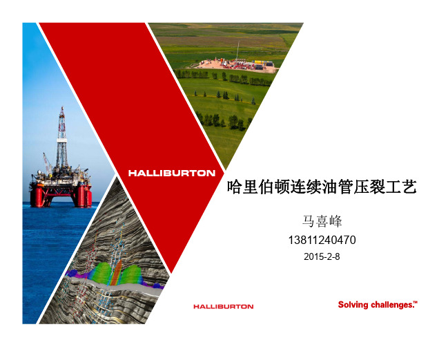
哈里伯顿固井工艺及固井新工具
俄罗斯固井质量测井仪器与哈里伯顿INSITE系列测井系统的挂接
俄罗斯固井质量测井仪器与哈里伯顿INSITE系列测井系统的挂接【摘要】本文介绍了俄罗斯固井质量测井仪器的基本特性及功能,重点是解决了实际生产中不同测井系统挂接的需求。
针对俄罗斯固井质量测井仪器与insite系列测井系统挂接之间存在的问题,包括gector地面采集系统的挂接;gector地面采集系统深度信号的获取;地面系统的供电组成;井下仪器3芯接头与insite系列19芯接头的转换问题等,提出了合理有效的解决方案,实现了两套不同系统之间的挂接,充分利用测井资源,提高了测井生产时效。
【关键词】声波变密度水泥胶结质量仪器挂接地面采集俄罗斯固井质量测井仪器即俄罗斯mak2—sgdt测井系统,采用声波变密度(mak2)和伽玛密度(sgdt)测井仪器相结合的组合形式定量的评价水泥胶结质量。
这套系统主要包括声波变密度测井仪、伽玛密度测井仪、gector地面采集箱、mak电源箱。
insite系列测井系统是美国哈里伯顿公司在excell2000系列测井系统基础上研制的新一代测井系统。
俄罗斯固井质量测井仪器和insite系列测井系统在测井中具有很大差异,测井系统整体结构大相径庭。
而俄罗斯固井质量测井仪器可以与insite测井系列在测井过程中的功能互补,通过两套系统的挂接,使两套系统在实际测井操作中协调工作,共同发挥它们的作用。
1 俄罗斯固井质量测井仪原理俄罗斯固井质量测井仪器采用声波变密度(mak2)和伽玛密度(sgdt)仪器相结合的形式评价水泥胶结情况。
mak2不提取首波绝对幅度的大小,而是研究首波的幅度衰减和时间特性;它测量首波到达接收器的时间、接收器记录的首波衰减、首波时差及首波衰减系数。
因此,mak2声波变密度仪器是通过测量首波衰减情况来评价第一、第二界面胶结质量。
sgdt伽玛密度仪器是通过放射源来反映水泥环的密度情况。
经过计算机处理,能够得到套管壁厚曲线、偏心率曲线、水泥平均密度曲线等。
通过这两种仪器测量的成果曲线信息,结合常规资料和地层密度等资料进行综合解释,综合评价水泥胶结质量、确定水泥返高和自由套管井段、检查套管损坏位置、检查套管程序以及确定套管相对与井壁的偏心率等。
哈里伯顿垂直钻井系统

节约水资源
垂直钻井系统采用高效的水循环 利用技术,能够减少对地下水的
开采和利用,节约水资源。
促进可持续发展
垂直钻井系统符合可持续发展的 理念,有利于保护环境和生态平 衡,推动经济社会的可持续发展。
对社会经济的推动作用
1 2
创造就业机会
垂直钻井系统的建设和运营过程中,需要大量的 人力资源和技术支持,为社会创造了就业机会。
随着技术的不断进步和应用需求的增加,哈里伯顿垂直钻井 系统将进一步发展智能化、自动化技术,提高钻井精度和安 全性,为矿产资源开发提供更高效、安全、环保的解决方案 。
05
哈里伯顿垂直钻井系统的价值与影响
对石油工业的价值与贡献
提高钻井效率
垂直钻井系统采用先进的钻井技术和设备,能够显著提高钻井效 率和成功率,缩短钻井周期,降低生产成本。
03
哈里伯顿垂直钻井系统的市场分析
市场需求分析
石油和天然气开采
随着全球能源需求的增长,石油和天然气开采行业对钻井技术的需求持续增加, 哈里伯顿垂直钻井系统在开采深层油气资源方面具有显著优势,因此市场需求较 大。
基础设施建设项目
垂直钻井系统在基础设施建设项目中也有广泛应用,如桥梁桩基、高层建筑桩基 等,这些项目的不断增加对垂直钻井系统的需求也相应增长。
竞争格局分析
市场竞争激烈
垂直钻井系统市场上存在众多竞争对手,包括技术实力雄厚 的国际企业和专业化的国内企业,市场竞争十分激烈。
差异化竞争
哈里伯顿垂直钻井系统凭借其技术优势和品牌影响力,在市 场上占据一定份额,但其他企业也在不断进行技术研发和创 新,形成差异化竞争的格局。
市场趋势与前景预测
技术创新推动市场发展
哈里伯顿垂直钻井系统
固井工艺技术介绍
DRI
固井可能带来的危害
涩北气田气层埋藏浅,分布井段长(408.0-1738.2m),层数多(54-79),气水界面复杂, 浅层气、浅层盐水活跃。台H6-1井、台6-7井,一开钻至800m下入表层套管固井后,候凝过
程中套管外地表窜出盐水和水溶气,被迫报废
台 H6-1 井 339.7mm 表 层 套 管 固 完井候凝时,北东方向约 250 米冒气水后目前情况 台 6-7 井 273mm 表层套管固 完井候凝时,地表窜出盐 水和水溶气
前 言
DRI
固井可能带来的危害
井喷——灾难性后果(墨西哥湾事故)
灌香肠、插旗杆——整井报废,单井段报废,经济损失巨大
挤毁套管——整井报废,单井段报废,经济损失巨大 油气水窜——单井段报废,降低开发效益
环空带压——开发隐患,增加作业成本、环境危害
超缓凝——延长作业时间、增加作业成本 返高不够——降低封固质量,增加补救作业成本 过早套损——单井报废,增加作业成本,降低开发效益
~100kN于悬挂处→憋压剪断球座销钉→开泵进行循环钻井液→
注前置液→注水泥浆→释放钻杆胶塞→替钻井液→钻杆塞与空 心耦合(耦合前降低替入排量) →碰压→放回压,检查浮箍是 否倒流→上提中心管,循环出多余的水泥浆→起钻候凝。
-24 -
钻井研究院
第一单元
固井工艺技术
DRI
尾管固井
-25 -
尾管悬挂器
专门研究如何用化学方法解决固井过程中遇到的问题。
具体地说,水泥浆化学就是通过研究水泥浆的组成和性 能,且予以科学地控制和调整,最终达到封隔地层、保 护储层和支撑套管的目的。
-32 -
钻井研究院
-23 -
钻井研究院
第一单元
固井历史上的重要事件

固井历史上的重要事件:1903:F·F·希尔将50袋水泥混合后的纯水泥浆倒入井内,用于封堵井底水层。
1919:哈力伯顿——在北德克萨斯成立注水泥事务所。
1920: 哈力伯顿——发明了射流水泥混合器。
1921:J·T·白奇曼、散塔克鲁兹水泥石油公司——发明了初期水泥试验技术。
1922:哈力伯顿——提出了双塞注水泥浆法专利技术。
1927:独星水泥公司——在印第安纳首次制造了高细度抗硫酸盐水泥。
1929:哈力伯顿——建立了第一个测定油井水泥性能的实验室。
1930:哈力伯顿、汉布莱石油与炼制公司、加利福尼亚标准石油公司——开始进行油井水泥研究工作。
1930:H·R·依尔文——取得了在套管外用扶正器方法的专利。
1930:搬土被引进到石油工业,用于钻井泥浆及水泥。
1932、1934:威拉姆兰诺与瓦尔特威尔斯——在加利福尼亚及墨西哥沿岸使用了射孔枪。
1934: B·C·克拉夫特等、加利福尼亚标准石油公司——提出了水泥稠化时间测定仪结构的报告。
1937:J·E·勒尔、哈力伯顿——制造了测定油井水泥性能的双容器装置。
1937:API——成立了油井水泥研究委员会。
1938:R·F·法里斯、斯塔诺林德油气公司——制造了第一台高温高压水泥浆稠化时间测定仪。
1939:汉布莱石油与炼制公司——在水泥内混入少量的卡诺特石(钒钾铀矿)以使用伽马测井法来确定套管外水泥返回顶部的位置。
1939:肯艾斯瑞特与布鲁斯巴斯特——在加利福尼亚第一次使用市售井壁刮泥器。
1940:M·M·肯莱——第一次用电缆进行井径测井,以确定所需水泥的量。
1952:API——批准了关于油井水泥实验的API规程32(第一版)。
1953:飞利浦斯石油公司——把降失水剂产品和硅藻土介绍到工业界。
1957:哈里伯顿——介绍了加重剂。
Multiple-Stage Cementing System(哈里伯顿分级固井工具)

CEMENTING HEADPARVEEN cementing Head is used for cementing the annular space between casing and bore hale during 2nd stage of well construction cycle. The cementing head is employed to connect the pumps of the cementing trucks to the casing string and provides access for insertion of the cementing plugs.Parveen's Cementing heads are available in sizes 4 1/2 ” to 20”, for working pressure of 2,000 to 10,000 psi. Cementing head sizes & working pressures are inversely related. Generally for smaller sizes mare working pressure and far larger sizes less working pressure are the requirements. Cementing heads could be of single plug or double plug types. Caps are “Acme” threaded or quick lock type and fitted with swivel chain assembly. The double plug cementing head has three valve manifold and two plunger assembly. Cementing heads are manufactured from solid forged rounds of allay steels AISI 4130/4140/ 4145 HEN-19 or equivalent material and are fully heat treated.CEMENTING OPERATIONSPARVEEN Cementing Head is suitable to carry out single stage as well as double stage cementing operation. It is provided with the following features:(a) Indicates when the top plug passes into the casing.(b) Simple in operation and provides easy loading of plugs.(c) Having manifold with lo-torque plug valve.(d) Provides continuous operation.(e) The plug container holds one or two plugs, the top plug and the bottom plug. The double plug container has athree in-torque valve manifold and two plunger assembly.(f) The length of plug containers are made to accommodate the standard length of plugs.(g) The cap is available with ACME thread and with lifting chain for lifting the plug container.(h) Adapters are available with all casing threads and buttress threads.(i) The standard adapters have a 6 inch Tong space with thread protectors.(j) The hammer unions used in manifolds are PARVEEN's make.CEMENTING MANIFOLDSCementing manifolds are supplied with cementing heads or alone as per customer preference. It is an assembly of unions, plug values, tee, nipples etc. These can be supplied in any size up to pressure ratings of I0,000psi pressure.NOTE: 1. PARVEEN reserves right to alter the design data if required.2. All dimensions are in inches.3. For other sizes & for single plug cementing head sizes please contact PARVEEN.4. For Nomemclature refer diagram at next page.CEMENTING HEAD CFO™Multiple-Stage Cementing Systemmultiple-stageFO cementer)is used to placestages of cement or othera casing string at differentalong the casing.This tool isand requiresthe use of astring and the sleevetools.These operatingthrough Halliburton toolas rental items.In addition,manufactured for customerare made of heat-treatedhardness of RC 21.are suitable for use with H-40,and N-80grades of casing.be used in sour servicegas –H 2S and sour oil)The Halliburton series of FO(full-opening)cementing tools consistsof the following equipment:•FO multiple-stage cementers•Opening and closing sleeve positioners•Standard isolation packers•Port valve isolation packers•RTTS™circulating valves•FO inflatable packer collarsFeaturesThe FO cementer has the following unique advantages:•Any number of tools can be run in the same string.•No plugs or seats must be drilled out at the cementer.•Operators can open or close the tool whenever necessary.•The tool can be used to test,treat,and evaluate a zone in the wellbefore it is reclosed.CEMENTINGHALLIBURTONFO stage cementer shown in a typical off-bottom cementing application where Delta Stim®sleeve collars,Swellpacker®isolation system and annular casing packers are all run in a single string.Sales of Halliburton products and services will be in accord solely with the terms and conditions contained in the contract between Halliburton and the customer that is applicable to the sale.H067683/09©2009HalliburtonAll Rights ReservedPrinted in U.S.A.HALLIBURTON FO sleeve with port isolation packer30/06/2000Slim-line Re-lining is a technique designed to fit a well liner with the minimum reduction of well diameter. It is based on using a Swage Packer to seal the base of the liner into the old casing or a screen. Briefly, a Swage Packer is a thin wall pipe with a vulcanized rubber cover that can be expanded radially using a high-pressure inflatable packer to create a well seal. The attached drawings P663A and P663B show the two most common methods of applying this technique.The first of these shows re-lining using a swaged packer and cementing the annulus between the liner and the existing casing. The basic installation steps, as indicated on the drawing are: • Clean the existing casing and inspect to ensure it’s ready to receive the liner. In some cases, this may require a deviation survey in addition to video inspection.• Attach the Swage Packer and one-way grouting valve assembly to the 1st joint of the liner. The drawing shows this as a welded connection but threaded or even glued and pinned connections are also possible.• Run the liner in to the required depth. Note that, if the liner is to tie back to the surface, the liner can be run as usual, however, it is also possible for the liner top is to terminate below surfacewhich is described below.• Make-up the High Pressure Swaging Packer, straddle pipe and low pressure cementing packer.• Run this assembly inside the new liner to locate the HP Swaging Packer adjacent to the Sage Packer. The two different packers each have separate inflation hoses to allow independentoperation.• Inflate the HP packer to sufficient pressure to deform the Swage Packer out into firm, sealing contact with the existing casing. This operation is controlled in terms of both inflation pressure and volume against pre-tested standards for each.• With the HP packer still inflated, inflate the LP cementing packer to isolate the one-way cementing valve.• Hook up a pumping head to the drill rods and establish circulation to the liner/casing annulus with water then switch over to cement grout and pump grout to fill the annulus.• Deflate the LP cementing packer and flush the excess grout out of the rods and straddle zone.Obviously, to minimize flushing, a water tail can be pumped following the cement and thestraddle pipe can also be set-up to accept a wiper plug if required.• To complete the re-lining simply deflate the HP packer and trip out of the hole.The liner can be manufactured from any compatible material, e.g. standard steel casing, PVC, ABS, FRP, etc. Since the liner is not deformed in any way and the Swage Packer will be expanded to a larger ID than the liner, it’s the liner itself which determines the minimum finished ID of the lined well. Selection of the liner will depend on factors such as minimum running and grouting clearance, method of joining, well fluid conditions, minimum allowable ID and, inevitably, availability.If using a thin wall or other low collapse strength liner, a third inflatable packer (or other closure method) may be run at the surface and the annulus between the drill rods and the liner can be water filled and slightly pressurized to prevent collapse during cementing. In this case it essential to pump a water tail after the grout, preferably with a wiper plug, as the liner must remain pressurized until the grout has reached initial set at least.The 2nd re-lining technique shown involves deforming both the Swage Packer and the liner. In this case, they are both usually manufactured from the same size pipe – either stainless steel or carbon steel as appropriate to the installation. The installation procedure is similar to that given above except for the steps involved in cementing the annulus. In their place, after performing the initial setting of the Swage Packer, the HP packer is deflated, moved up hole and re-inflated to swage out the liner. This process continues in a stepwise fashion until the complete liner has been swaged out.Normally, it is the swaged ID of the Swage Packer which represents the minimum ID of the lined well in this case. Typically, for water wells, this will be around ½” (13 mm) less than the existing casing ID and thus represents a minimal reduction of diameter.As mentioned above, it is possible to locate the liner top some depth below surface. In this case, following make-up of the liner to the length required, the liner is hung off and the packer assembly is run into the liner on drill pipe. Locating the HP packer adjacent to the Swage Packer, as previously, this packer is inflated to a pressure sufficient to provide a high strength anchor on the inside of the liner but less than that required to begin setting the Swage Packer. The liner is then lowered to its required depth using the drill pipe and the frictional anchor provided by the inflate HP packer. On depth, the pressure in the HP packer is simply increase to set the Swage Packer.Apart from the obvious advantages of these techniques to produce very slim-line re-lines, it may be noted that at no time is a conventional drill rig required. All operations may thus be performed using a crane and simple casing & rod slips thus reducing costs and scheduling constraints. Furthermore, there is no need to kill a producing well, even an artesian well, in order to reline using these techniques as the inflatable packers may be used, in conjunction with appropriate surface equipment, to prevent contamination of the aquifer with cement or uncontrolled flow situations.The Slim-line Re-lining techniques described were first introduced by AGE Developments Pty Ltd (AGE) of Perth, Western Australia in 1993 and are offered internationally by Inflatable Packers International (IPI).By Clem Rowe, Managing Director, Inflatable Packers International Pty Ltd © 30 June, 2000。
水下释放塞固井工艺.
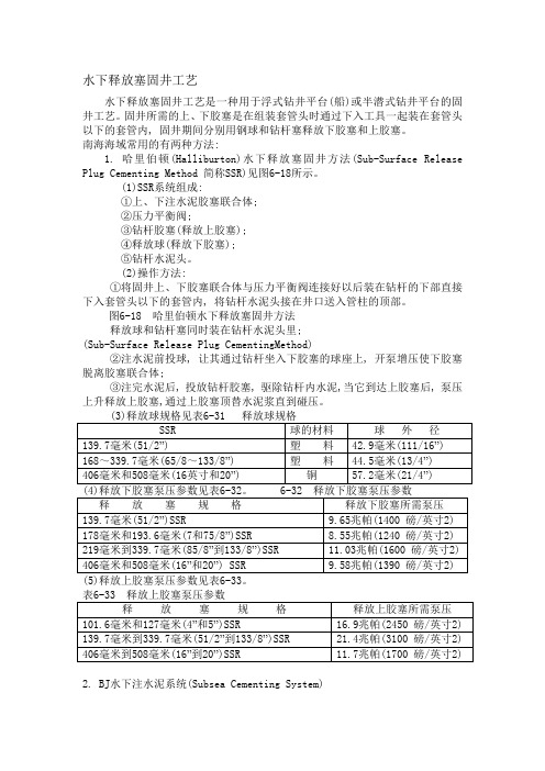
水下释放塞固井工艺水下释放塞固井工艺是一种用于浮式钻井平台(船)或半潜式钻井平台的固井工艺。
固井所需的上、下胶塞是在组装套管头时通过下入工具一起装在套管头以下的套管内, 固井期间分别用钢球和钻杆塞释放下胶塞和上胶塞。
南海海域常用的有两种方法:1. 哈里伯顿(Halliburton)水下释放塞固井方法(Sub-Surface Release Plug Cementing Method 简称SSR)见图6-18所示。
(1)SSR系统组成:①上、下注水泥胶塞联合体;②压力平衡阀;③钻杆胶塞(释放上胶塞);④释放球(释放下胶塞);⑤钻杆水泥头。
(2)操作方法:①将固井上、下胶塞联合体与压力平衡阀连接好以后装在钻杆的下部直接下入套管头以下的套管内, 将钻杆水泥头接在井口送入管柱的顶部。
图6-18 哈里伯顿水下释放塞固井方法释放球和钻杆塞同时装在钻杆水泥头里;(Sub-Surface Release Plug CementingMethod)②注水泥前投球, 让其通过钻杆坐入下胶塞的球座上, 开泵增压使下胶塞脱离胶塞联合体;③注完水泥后, 投放钻杆胶塞, 驱除钻杆内水泥,当它到达上胶塞后, 泵压上升释放上胶塞,通过上胶塞顶替水泥浆直到碰压。
2. BJ水下注水泥系统(Subsea Cementing System)(1) 系统组成(见图6-19):上、下胶塞联合体;(2)下入工具总成;③释放球;④钻杆胶塞;⑤钻杆水泥头。
(2) 操作方法:①将上、下胶塞联合体装在下入工具的下部;②将下入工具装在钻杆的底部, 并用钻杆送入套管头以下的套管内;③注水泥前投球, 让其通过钻杆坐入下胶塞的球座上, 开泵增压使下胶塞脱离胶塞联合体;④注完水泥后, 投放钻杆胶塞, 驱除钻杆内水泥, 当它到达上胶塞后, 提高泵压释放上胶塞,通过上胶塞顶替水泥浆直到碰压。
(5)释放上、下胶塞所需泵压见表6-34。
哈里伯顿测井新技术

46% shorter
LOGIQ – Quad
30% lighter
© 2009 Halliburton. All Rights Reserved.
6
Wireline Sensor Toolbox 2009 - Open Hole 裸眼井仪器系列 -2009
Hostile Environment/Slimhole Magnetic Resonance Coring Tool Formation Tester Resistivity Imaging Ultrasonic Imaging
26
MRILab
实时监测:气层
T1 Distribution Time History
T1 Distribution
Gas Oil Filtrate Oil Filtrate
Gas
© 2009 Halliburton. All Rights Reserved.
27
RDT特点总结 RDT特点总结
① 模块式设计使测试更具灵活性
根据不同的地层条件和测试目的,选用不同的模块组合
② 针对不同地层特点设计了多种抽吸极板,覆盖所 有地层类型 ③ 高效率获取高质量的有代表性的PVT样品
快速的样品泵出时间 MRILab和其他流体传感器对样品进行多参数分析,实时 监测样品的污染程度 通过压力控制确保单相采样
© 2009 Halliburton. All Rights Reserved.
复杂储层评价
复杂储层的评价内容和测井组合
地层 1 2 3 4
碳酸盐 火成岩 变质岩 致密砂岩
储层类型 孔隙度及孔 隙结构 识别
XRMI/OMRI FCAST WSTT XRMI/OMRI MRIL 常规曲线
哈里伯顿测井新技术

• 先进的非对称线圈排列的阵列感应
• Intrinsic sensitivities from 6 to 80 inches
• 内部线圈间距从6到80英寸
• Improved accuracy and tolerance for poor logging conditions
• 仪器结构优化改善极板与井壁的接 触,适应各种复杂井眼
• Full-size borehole range – 6” to 20” (15 – 50cm)
• 适用于各种常见井眼
Wireline Sensor Toolbox 2008 - Open Hole 裸眼井仪器系列 -2008
高温小井眼仪器 核磁共振 取心器 地层测试器 电阻率成像 超声成像
流体密度仪(放射性) 持气率计 缆头张力计 串接式转子流量计 XY 井径仪 自然伽马 井径 快速响应温度计 石英晶体压力计 温度-慢速响应 张力-压缩力-节箍定位组合仪 电容阵列持水率仪 互相关流量计
SONDEX 仪器全兼容
记忆式生产测井系列 Ultra-Link 系列
缩写
CCL CFB CFJ CFS CWH DBT FDD FDP
• Half the length • 长度较前减半 • Two-thirds the weight • 重量较前减1/3 • Safer to handle • 操作更安全 • Faster rig up and down • 组装拆卸更快 • Eliminates ‘rat hole’ drilling • 减少鼠洞(口袋)的长度 • Downhole Tools Incorporate the
哈里伯顿页岩气水力压裂技术-滑套完井
12. 在所有油层的措施作业完成后,打开每个 滑套,开始生产。
投球打开操作程序 1. 组装完井管串开始下入。完井管串底部为 浮鞋,随后依次是浮箍、所需数量的Swellpacker 膨胀封隔器系统和带有球座的投球开关 Delta Stim增产滑套。
7. 要有充足的时间让封隔器胶筒和液态碳氢化 合物发生作用,并密封隔离产层。
8. 将带有机械开关工具的连续油管或油管下入 到预定油层的增产滑套并操作打开滑套。
9. 对油层进行增产措施作业。
10. 如井筒中的其它油层需要增产措施,用液 压启动开关工具将增产滑套关闭。然后转到第 二个油层的增产滑套,将其打开以便进行措施 作业。
该技术可根据油气藏情况制定完井方案 根据油气藏情况,可以采用Swellpacker®封隔系统或 Wizard® III 封隔器对裸眼实现封隔。
Delta Stim 增产滑套可通过投球或连续油管/普通油管 下入机械/液压开关工具进行开关。
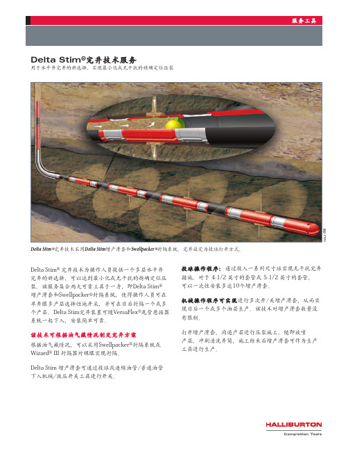
投球操作程序:通过投入一系列尺寸球实现无干扰完井 措施。对于 4-1/2 英寸的套管或 5-1/2 英寸的套管, 可以一次性安装多达10个增产滑套。
Delta Stim®完井技术服务
用于水平井完井的新选择,实现最小化或无干扰的精确定位压裂
服务工具
HAL21998
® ® Delta Stim 完井技术采用Delta Stim增产滑套和Swellpacker 封隔系统。完井设定为投球打开方式。
Delta Stim® 完井技术为操作人员提供一个多层水平井 完井的新选择,可以达到最小化或无干扰的精确定位压 裂。该服务集合两大可靠工具于一身,即Delta Stim® 增产滑套和Swellpacker®封隔系统,使得操作人员可在 单井眼多产层选择性地开采,并可在日后封隔一个或多 个产层。Delta Stim完井装置可随VersaFlex®尾管悬挂器 系统一起下入,安装简单可靠。
哈里伯顿压裂井下工具介绍
▌ 井底混配 高排量 实时控制井底砂浓度 实时监测储层响应 裂缝远端转向 ▌ 层间封隔
设置砂塞 动态封隔 (伯努力效应)
▌ 控制砂堵风险
更激进的泵注程序 高砂浓度 大粒径支撑剂 高导流能力 快速提高砂浓度,降低液量,缩 短时间
8
© 2014 HALLIBURTON. ALL RIGHTS RESERVED.
20
© 2014 HALLIBURTON. ALL RIGHTS RESERVED.
CobraMax HJA中国区有现货
21
© 2014 HALLIBURTON. ALL RIGHTS RESERVED.
CobraMax DM(连续油管缝内转向压裂)
CobraMax DM 压裂技术结合选层,定点注砂和水力压裂为一体,实现 分段压裂和缝内导向的目的。该工艺在油管内泵注高浓度携砂液,环空 泵注不携砂压裂液,这样不但避免冲蚀套管,还使井下砂浓度灵活可 控,完成泵置砂塞和缝内导向的目的。
双通道,低风险 水力喷砂射孔 完成先进的压裂工艺 不需要过顶替 精确裂缝定位 精确支撑剂泵送 降低地面水马力需求 降低作业占地面积
11
© 2014 HALLIBURTON. ALL RIGHTS RESERVED.
TSTM Hydra-Jetting Tool --TS新工具
RapidFracTM System (单段多入口压裂滑套)
Pinpoint Stimulation (连续油管辅助式压裂)
5
© 2014 HALLIBURTON. ALL RIGHTS RESERVED.
提纲
▌ 分段压裂工艺概述 ▌ 连续油管辅助式压裂 ▌ 特殊连续油管井下工具 ▌ 讨论
中石化普光气田井下工具协议-哈里伯顿
2 完井方案简述
针对普光气田酸性气井,推荐 MHR 密封插管式液压永久封隔器完井方式。 此方案所提供的完井工具满足普光气田的使用环境-高酸性气井完井要求。 金属材质选用高强度镍铬合金 Inconel 718,具有高抗腐蚀性,保证了在普光气 田高硫化氢和二氧化碳的井况下能够长期工作。且满足压裂酸化等施工作业要求。 所有的完井工具承受压差等级为 70MPa。完井工具管柱结构设计从上向下为安全 阀流动短节、井下安全阀、锚定密封总成、液压坐封封隔器、磨铣延伸筒、转换 接头、坐落接头、剪切球座,外加配套的附件。 完井方案设计简单可靠,上部设计井下安全阀,保证油气井在紧急状况下安 全可靠关闭,及时切断关闭油气井。哈里伯顿的井下安全阀为业界公认的非常可 靠的安全阀供应商。此次提供的安全阀具有内径大,外径小,可以保证顺利下入 7”的套管中。此安全阀为自平衡式,在不打平衡压力时也可以安全开启安全阀, 保证作业的方便。安全阀为全金属密封(气密封)。安全阀设计简单可靠,现场操 作方便。 管柱下部设计使用的哈里伯顿MHR液压坐封永久式封隔器,此封隔器为业界 公认的非常可靠的封隔器,具有液压坐封,一次管柱下入即可完成管柱安装,使 得作业非常简单、安全。封隔器有双向卡瓦,3 排胶筒设计,液压坐封机构在封
管;备用坐封封隔器;油管试压;且堵塞器下部可悬挂压力计对地层进 行监测。 注:此套完井管柱已在四川罗家寨气田现场应用,通过测试,已取得成功。
4
3.2 完井工具清单(MHR 封隔器)
井下工具名称 安全阀控制管线 控制管线保护器 流动短节 安全阀 锚定密封
封隔器 磨铣延伸筒
变扣接头
坐落短节 球座接头
型号 1/4″ 3 1/2 3 1/2″ NE TRSV
½-12.6 VAM-TOP Box Halliburton Millout Extension 磨洗延伸 筒
哈里伯顿测井新技术

卡点指示/倒扣服务 化学切割服务 径向火炬切割器
其它仪器/服务 它仪器 服务
Applied RCT
SONDEX 仪器全兼容
记忆式生产测井系列 Ultra-Link 系列
Enhanced tivity 增强了连通性
Houston Hub
Insite Data Base
市场
作业基地 储层解释 Ethernet telemetry IP IP IP IP IP IP Each tool has its own IP address 每一支仪器都有自 己的IP地址 己的 地址
套管井仪器
仪器名称
缩写 CBT CBL RBL/CBL GNST HGNC PERF GR CCL TMDL RMT SpFL MAC MIT
仪器名称
缩写 CCL CFB CFJ CFS CWH DBT FDD FDP FDR GHT HTU ILS PDC PGR PLC PRT QPS PRTN HTUB CAT CCF
Assist in completion of new wells(完井辅助 完井辅助) 完井辅助
Cement integrity Perforating Solutions Production Hardware (固井检查) 固井检查) 射孔方案) (射孔方案) 生产所需硬件) (生产所需硬件)
声波 地层密度
中子孔隙度 电阻率 自然伽马 自然伽马
Wireline Sensor Toolbox 2008 - Cased Hole 套管井仪器系列 -2008
水泥胶结 (3.25") 水泥胶结 (1 11/16") 径向水泥胶结 - CBL (CSS) 伽马中子仪 高温伽马中子仪带 CCL 射孔服务 自然伽马 磁定位 多门热中子衰减岩性测量仪 储层监测仪(过油管碳氧比) 能谱水流仪 多臂井径仪 多独立臂井径仪 放射性示踪仪
哈利伯顿固井工艺及新工具介绍

• Conventional Cement Job / Casing in Hole 常规固井/下套管
CO2STOP Slurry CO2STOP体系
• •
HPHT Slurry 高温高压水泥浆 Cement Assurance Tool & Swell Packer 固井保障工具和油气膨胀封隔器
Return
How to achieve zone isolation? 提高固井质量的几个要素
•• Mud Conditioning Mud Conditioning 处理好泥浆 处理好泥浆 •• Mechanical Aids机械辅助 Mechanical Aids机械辅助 – Pipe Movement – Pipe Movement 活动管柱 活动管柱 – High Port Up-Jet Float Shoe – High Port Up-Jet Float Shoe 向上喷射式浮鞋 向上喷射式浮鞋 •• Centralization Centralization 套管居中 套管居中 •• Fluid Velocity Fluid Velocity 流速 流速 •• Spacers & Flushes Spacers & Flushes 隔离液及清洗 隔离液及清洗
Case Histories – Expandable Casing 案例-可膨胀尾管
• To Date (1/2003) With ChannelSeal™
固井泵 哈里伯顿HT-400 pump

CementingHALLIBURTONHT -400™ PumpThe Industry StandardH alliburton’s HT-400™ Pump is a lightweight,rugged,versatile unit that was introduced in 1957.Its name denotes Horizontal Triplex and its original rating of 400 horsepower.Since its debut,the basic design has been improved and upgraded until it now is rated at 800 hp maximum in some configurations.The pump has performed millions of operating hours in fracturing,acidizing,cementing,and sand and water control work.FeaturesThe Halliburton twin-pump or flexibility concept is particularly useful when precise pumping ranges andcontrols are required.Halliburton exclusively manufactured the HT-400 pump power end,so that practically all parts are interchangeable.The exception is that the power end case is built in both left- and right-hand configurations.Internal parts,including the proven worm/ring gear sets,are identical,only the case is different.Power ends can be fitted with any of the five sizes of fluid ends – 3 3/8”,4”,4 ½”,5”and 6”plungers – each with characteristics suitable for specific applications.Power end components:•Case and Drive Gears:Power End cases aremanufactured exclusively by Halliburton in both left- and right-hand models.They are made of high-strength weldments of Halliburton design.They are not interchangeable.•Crankshaft:Heat-treated steel forgings are used to manufacture crankshafts.All cranks are the same,even for left- and right-hand units.•Connecting Rods:Connecting rods are made from aluminum forgings.The identical rods are internally drilled to provide lubrication to the crosshead pins.•Crossheads:Crosshead bodies are made of heat-treated steel alloy castings.They are fitted with replaceable,high-leaded bronze shoes on both top and bottom.•Lubrication:Standard self-contained power endlubrication system is pressurized by an internal crescent gear-type pump driven off the end of the worm gear.Positive pressure lubrication is supplied to the crosshead slides,gear support bearings,crankshaft throws and crosshead pins.•Cooling:Tube-and-shell coolers are optional add-on components,which provide remote cooling capacity.The HT-400 pump can be fitted with radiator-type,air-to-oil or water-to-oil cooling systems as well.Spacers are special components designed to separate the fluid end from the power end of the HT-400 pump.The interchangeable spacer insures that fluids being pumped do not contaminate the power end and cause premature failures.Each fluid end package is manufactured from three separate chambers – all identical and completely interchangeable.If one chamber of a fluid end should cause trouble,it can be changed quickly and the pump returned to duty.Fluid End components:•Chambers:The fluid end is constructed from threeseparate but identical forged and heat-treated chambers.Fluid ends can be supplied in any of five plunger sizes and each size can be fitted to the standard power end without alteration of either fluid or power end.•Valves and valve seats:Fluid ends are fitted withreplaceable,carburized valves and seats of Halliburton design and manufacture.Most of the valve assembly parts are interchangeable between suction and discharge ports within a given size and some are even interchangeable between sizes.•Lubrication:A separate lubrication system supplies lubricant to the fluid end package.H A L 17345Fluid end viewSales of Halliburton products and services will be in accord solely with the terms and conditions contained in the contract between Halliburton and the customer that is applicable to the sale.H04798 04/06© 2006 Halliburton All Rights ReservedPrinted in U.S.A.TestingEach HT-400 pump undergoes rigorous testing before it is placed in service.Fluid end chambers are tested individually to pressures far beyond the anticipated operating pressures and then tested again when they are assembled into three-chamber fluid ends.A third test is performed after the fluid end is attached to the power end assembly.Power ends are submitted to equally rigoroustesting in a Halliburton test facility.Pumps are run for over an hour at various speeds and at various pumping pressures before they are installed on a unit.After the unit is completed,each pump is further tested during the unit checkout.H A L 17346Mounted on a skid — close-upFluid end ring gear viewMounted on Advantage™ skid unit — side viewH A L 17347H A L 17348。
哈里伯顿固井工艺及固井新工具

Alternative Cementing Approach: 优化固井方案 -Tail Slurry -SwellpackerTM system
• • Installed in well when running casing 随套管下入 Deploys when catalyst comes in contact with element (currently liquid hydrocarbons) 见油气膨胀 • • • Fills Micro-Annulus 填充微裂缝 Remains flexible for the life of the well 保持膨胀特性 Heals itself to maintain future seal 自动修复,保持长久密封
• • • • • • • •
Slurry Weight: 20.0 ppg (2.4 SG) Slurry Weight: 20.0 ppg (2.4 SG) Pumping Time @70bc: 4:39 at 190° C BHCT Pumping Time @70bc: 4:39 at 190° C BHCT Fluid Loss: ~50 ml at 190°C BHCT Fluid Loss: ~50 ml at 190°C BHCT Free Water: 0% at 45° Free Water: 0% at 45°
4.5inx8.15inx9m Sw ellpacker 5.5inx8.15inx9m Sw ellpacker 6.625inx8.15inx9m Sw ellpacker 7inx8.15inx9m Sw ellpacker
油井水泥、外加剂_以及固井工艺技术
固井工程处固井技术研究所
马小龙
概
述
随着石油勘探开发事业的发展,钻井技术的进步给固井提出 更高的技术要求。用纯水泥固井已成为过去,一代又一代的油井 水泥外加剂问世,用以改善水泥浆性能,使之能适应深井或超深 井、特殊井复杂地层等的固井施工,达到封隔地层、支撑套管和 地层、保护油气层、延长油井寿命和提高石油采收率的目的,同 时外加剂的应用水平的提高反过来也促进固井技术的发展。如今, 固井工程已成为石油工程、化学工程、硅酸盐科学、高分子科学、 流变学等多学科互相渗透的综合学科。
第二节 油井水泥外加剂
在钻井过程中,水泥的用量是相当大的。油井水泥的外加剂 是用来调整水泥浆性能的化学助剂。50年代,固井被看作是一门 “技艺”,而70至80年代它已成为多种学科互相渗透的综合科学 “固井学”了。外加剂的作用和地位超过了水泥本身,有人认为 “油井水泥总是作为外加剂的载体用于固井工程中”。外加剂是 指掺入量小于或等于水泥重量5%,主要通过物理或化学的作用使 水泥浆达到某种性能。油井水泥外加剂主要可分八大类型:
未能及时监测到油气上窜,井控失效
– 负压力测试解读错误,油气井完整性未满足要 求,就进行下一步的施工 – 井控监督未及时下达指令 – 紧急停车系统失效,造成油气点燃
油气在深水平台上点燃
– 导流至泥浆天然气分离装置时天然气泄漏至钻 机平台 – 消防系统未能组织油气点燃
紧急封井器未能及时密封
– 紧急封井器未能封住井口
环空水泥密封性差
充氮水泥体系复杂,影响因素
多 水泥浆体积少,易受污染(充 氮水泥45桶) 未加降失水剂
未进行全面的室内实验
充氮水泥可能稳定性差,氮气 会上窜
哈利伯顿固井工艺及新工具介绍

下部井段使用合成基ChannelSeal™
• Use Water-Based ChannelSeal™ as a Lead Slurry Use 使用水基ChannelSeal作为领浆 • Extended Gel-Time Cement Slurry 凝结时间延长的水泥浆
CBL with Synthetic Based ChannelSealTM 合成基ChannelSeal CBL测井结果
• Placed In Well Prior To Running Casing • Casing Installed and Cemented • Easily Displaced But Will Set If By-passed • Performance Range
• 55°F (10°C) to 300°F (175°C) • BHP of 12,500 psi (highest tested)
Mud Conditioning 泥浆处理
LOW MOBILITY MUD MOBILE MUD
FILTRATE
FILTRATE
CEMENT
FILTER CAKE CASING
FORMATION
Comparison of Annular Clearance to Primary Cementing Success 环空间隙对固井质量的影响
• 下套管前注入 • 下套管和固井 • 容易顶替,即便窜槽 也能封固 • 性能
– 55°F (10°C) to 300°F (175°C) – BHP of 12,500 psi (highest tested)
• No Spacer Is Needed For Separating the ChannelSeal™ Fluid From the Cement Slurry Or Improving Mud Displacement
哈里伯顿水平井压裂新工艺SurgiFrac介绍

水平井压裂新工艺介绍•SurgiFrac水力喷射压裂工艺哈里伯顿能源服务公司提高低渗低孔水平井的产量通常的水平井完井方式套管固井割缝管/筛管加封隔器割缝尾管或裸眼井垂向渗透性(Kv)core=0.001md(Kv)plug=0.1md(Kh)core=0.2md(Kh)plug=0.2md薄泥岩层~0.05in(Kv)plug/(kh)plug=0.5(Kv)core/(kh)core=0.005泥岩层影响水平井产量水平井压裂改造•制造横切或纵向的裂缝•避免同时产生多裂缝•消除裂缝弯曲横切裂缝纵向裂缝SurgiFrac(水力喷射压裂):是一种精确有效,可在单井中选择裂缝的位置并产生多个裂缝的增产方式。
Dr. Jim Surjaatmadja(发明者)哈里伯顿能源服务公司喷射泵技术•把一束流体的动能转化成多束流体的压力(势能)的技术•Boost pressure(压力提升):使低能量的流体的压力的提升。
应用于人工举升,及混浆系统W f W jW a水力压裂•1948 年Stanolind油气公司首次采用•现今的压裂技术的发展:–提高压力,排量,采用大型压裂,提高砂比–采用人工支撑剂–改变携砂液种类:CO2, N2 泡沫, 胶液, 柴油, ...•裸眼井压裂–尝试过一些方法但不可行性:–砂塞,化学塞….–跨式双封隔器–Hail Mary(超高排量压裂): 80 m3/min用传统压裂工艺产生小裂缝封隔器小裂缝造成液体逃逸出封隔层压裂液出口SurgiFrac 工艺过程压力分布流体的流动高Bernoulli’s公式:v2/2 + p/ρ= CSurgiFrac是如何工作的...•一定要知道裂缝的方向( 30 度以内)•喷嘴位置就是射孔位置,和裂缝产生的位置。
•Bernoulli 效应使裂缝入口处的压力在井筒中处于最低。
•环空的液体补充支持裂缝增长SurgiFrac 概念开始射流环空注入压力分布低高SurgiFrac 概念低沙比携砂液冲击并产生洞穴环空压力比裂缝产生所需要的压力低200 psi(1.38 MPa)压力分布低高SurgiFrac 概念开始的时候,射流被反射回环空压力在洞穴底部提高压力分布低高SurgiFrac 概念液体在洞穴中集聚使压力升高产生裂缝压力在洞穴底部提高压力分布低高SurgiFrac 概念射流使环空液体被吸入洞穴初期裂缝开始生成,液体得以进入地层压力分布低高SurgiFrac 概念环空液体不断被吸入洞穴压力的最高点裂缝继续增长压力分布低高可能应用SurgiFrac的完井方式Chertno acid in curvefor re-entryshow of hydrocarbonacid frac sand fracLimestone Sandfrac with acid经济投入的对比对设备需要的减少体现出经济效益SurgiFrac: 作业时间缩短–一趟管柱油管注入排量:16.5 BPM @ 7200 psi or 2.62 m3/min @ 49.6 Mpa.(2911 HHP)环空注入排量:6 BPM @ 434 psi or 0.95 m3/min @ 3 Mpa. (64 hhp)5-7台压裂车/混砂车。
- 1、下载文档前请自行甄别文档内容的完整性,平台不提供额外的编辑、内容补充、找答案等附加服务。
- 2、"仅部分预览"的文档,不可在线预览部分如存在完整性等问题,可反馈申请退款(可完整预览的文档不适用该条件!)。
- 3、如文档侵犯您的权益,请联系客服反馈,我们会尽快为您处理(人工客服工作时间:9:00-18:30)。
Cementing Discussion Topic 汇报内容
• How to achieve zonal isolation? 提高固井质量的几个要素
Traditional Cementing Approach:
传统固井方法
CSG. SHOE
TVD
MD
O riginal D esign
W ellLIF E on P ipe
RKB
Alternative Cementing Approach:
优化固井方案
-Lead & Tail
363.3 363.3
Loss of Zonal Isolation 解决封固井段有漏失的问题
BEFORE
之前
Gas Flow
SwellpackerTM
System
AFTER
之后
Complete Seal
Cracks
WellLife® Service
Additives
Complete Seal
Debonding
The Cement
++ 22..00%% SSCCRR--550000 ++ 00..55%% HHRR--2255 ++ ++ 11..55 ggaall//sskk LLaatteexx 22000000 ++ 00..1155 ggaall//sskk SSttaabbiilliizzeerr 443344CC ++ 00..0011 ggaall//sskk DD--AAiirr 33000000LL
500
7250
450
6525
400
5800
350
5075
300
4350
250
3625
200
2900
150
2175
100
1450
50
725
0
0
8,4 8,6 8,8
9
9,2 9,4 9,6 9,8 10 10,2 10,4 10,6 10,8
Hole ID [in]
使用Swell封隔器与常规固井方法的对比
• aids deployment • elastomer support
SwellpackerTM Lite System
• Slip on design
Cement Assurance™ Tool Components 固井保障工具组成
• Polymer合成橡胶 • End Rings端环
Customer Base Pipe
Debonding
The Cement
Assurance™
Tool
Complete Seal
Thank you! 谢谢大家!
Mud remains in place on low side
Element swells to fill mud channel and voids
Extremely adaptable to borehole anHdeaclaesding wall irreguMlaurdities channel
Long term: Sealed 长期 : 密封
Loss of Zonal Isolation 解决封固井段有漏失的问题
BEFORE
之前
Gas Flow
SwellpackerTM
System
AFTER
之后
Complete Seal
Cracks
WellLife® Service
Additives
Complete Seal
by Easywell Technologies 基于Easywment Assurance™ Tool 固井保障工具
Swelling Element
• 12mm thickness < 7 5/8” • 16 mm thickness 7 5/8” OD >
• 1,000 PSI rated 压差1000 PSI
基管
端环
高分子胶筒
胶筒设计原则
4.5
″
• 可在任何尺寸的基管上加工
• 越小基管,越厚胶筒
• 胶筒越厚,越大膨胀,越高压差
5.5
″
• 越长胶筒,越高承压能力 6.625 ″
• 可以膨胀到不规则井眼或套管
7″
8.15″
胶筒设计原则
Differential pressure [bar] Differential pressure [psi]
Slurry Design (Example 2) 水泥浆设计
•• LLaaffaarrggee GG CCeemmeenntt ++ 4400%% SSSSAA--22 ++ 8800%% MMiiccrrooMMaaxx ++ 00..55%% SSAA 554411 ++ 11..22%% HHaallaadd®®--441133 ++
750
10875
4.5inx8.15inx9m Sw ellpacker
700
5.5inx8.15inx9m Sw ellpacker
10150
650
6.625inx8.15inx9m Sw ellpacker 9425
600
7inx8.15inx9m Sw ellpacker
8700
550
7975
-Tail Slurry
-Gas Tight Slurry
1247 1266
-SwellpackerTM system
Short term: Sealed 短期 : 密封
Long term: ++??? 长期 : ???
3307 4972 4036 6675 4431 7380
Short term: Sealed 短期 : 密封
• Standard API casing sizes 标准套管尺寸
• Custom sizes available 尺寸可定制
• Installed at wellsite or pipe yard 在现场或车间安装
Element Length
• 1 meter (3.3 ft)
End Rings
•• SSlluurrrryy WWeeiigghhtt:: 2200..00 ppppgg ((22..44 SSGG)) •• PPuummppiinngg TTiimmee @@7700bbcc:: 44::3399 aatt 119900°° CC BBHHCCTT •• FFlluuiidd LLoossss:: ~~5500 mmll aatt 119900°°CC BBHHCCTT •• FFrreeee WWaatteerr:: 00%% aatt 4455°°
• Fills Micro-Annulus 填充微裂缝
• Remains flexible for the life of the well 保持膨胀特性
• Heals itself to maintain future seal 自动修复,保持长久密封
Swellpacker™ 系统组成
• 基管 • 胶筒 • 端环
End Ring
Polymer
End Ring
Cement Assurnce Tool 固井保障工具
¾ Does Swell Technology Enhance Safety? 提高安全性 9 Well, NO additional personnel are required! 不需额外的人员 9 And there are NO hazardous materials 不含有害物质 9 NO pressure required 不需坐封压力 9 Pumping, NO! 不需泵注 9 Over pull or rotation, NO! 不需过拉或旋转 9 Simple handling, YES! 处理简单
Assurance™
Tool
Complete Seal
Micro annulus – The Problem 解决微环空问题
Cement
Casing
Micro annulus
The Cement Assurance™ Tool 固井保障工具
Good mud removal on high side
The Cement Assurance™ Tool 固井保障工具
• Installed in well when running casing 随套管下入
• Deploys when catalyst comes in contact with element (currently liquid hydrocarbons) 见油气膨胀
Planning is essential in HPHT cementing 高温高压固井方案至关重要
• Lab testing 实验室试验 – Simulate job conditions as accurately as possible – Do not assume standard API conditions – Strict quality control of all blends (SSA-1 content) – Cementing rep. offshore/onshore in charge of bulk management – Quality control all materials and perform confirmation testing using field samples – Material traceability back to producer – Aim for a single chemical batch number, especially for retarders. – Communication is important to remain proactive – Allowance in design for change in plans
