XAUIXLAUI高速总线简介
XAUI XLAUI CAUI 40GE 100GE
在以太网标准中,MAC层与PHY层之间的10Gbps/40Gbps/100Gbps速率等级所对应的接口分别为XGMII/XLGMII/CGMII,由于XGMII/XLGMII是并行总线,而且采用的是单端信号,HSTL电平,最大传输距离只有7cm。
所以在实际应用中,X GMII/XLGMII基本上被XAUI/XLAUI替代。
XAUI/XLAUI是四通道串行总线,采用的差分信号,CML逻辑传输,并且进行了扰码,大大增强了信号的抗扰性能,使得信号的有效传输距离增加到50cm。
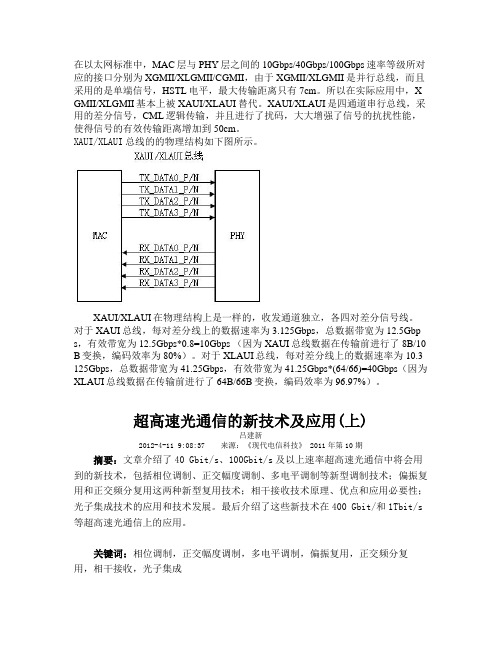
XAUI/XLAUI总线的的物理结构如下图所示。
XAUI/XLAUI在物理结构上是一样的,收发通道独立,各四对差分信号线。
对于XAUI总线,每对差分线上的数据速率为3.125Gbps,总数据带宽为12.5Gbp s,有效带宽为12.5Gbps*0.8=10Gbps (因为XAUI总线数据在传输前进行了8B/10 B变换,编码效率为80%)。
对于XLAUI总线,每对差分线上的数据速率为10.3 125Gbps,总数据带宽为41.25Gbps,有效带宽为41.25Gbps*(64/66)=40Gbps(因为XLAUI总线数据在传输前进行了64B/66B变换,编码效率为96.97%)。
超高速光通信的新技术及应用(上)吕建新2012-4-11 9:08:37 来源:《现代电信科技》 2011年第10期摘要:文章介绍了40 Gbit/s、100Gbit/s及以上速率超高速光通信中将会用到的新技术,包括相位调制、正交幅度调制、多电平调制等新型调制技术;偏振复用和正交频分复用这两种新型复用技术;相干接收技术原理、优点和应用必要性;光子集成技术的应用和技术发展。
最后介绍了这些新技术在400 Gbit/和1Tbit/s 等超高速光通信上的应用。
关键词:相位调制,正交幅度调制,多电平调制,偏振复用,正交频分复用,相干接收,光子集成无线3G、高清视频、高速宽带上网和云计算等业务的需求推动了网络IP流量的快速增长,人们对通信带宽的需求也在不断增长,提高传输速率是提高传输带宽的一项重要技术。
高速电路设计中,走线的等长、关键信号的阻抗控制、差分走线的设置 -- infohunter...(转载)
摘要:本文首先简述了高性能ARM9微处理器EP9315集成的外设接口及硬件结构框架,提出了当前高速电路设计中的问题;然后,详细介绍了利用Allegro实现嵌入式系统中SDRAM和IDE总线接口的电路设计;最后以Cirrus Logic公司的CS8952为例,阐述了物理层接口芯片的布线准则及其在Allegro中的实现。
关键词:嵌入式系统; Allegro;等长;差分对;阻抗控制引言随着嵌入式微处理器主频的不断提高,信号的传输处理速度越来越快,当系统时钟频率达到100 MHZ以上,传统的电路设计方法和软件已无法满足高速电路设计的要求。
在高速电路设计中,走线的等长、关键信号的阻抗控制、差分走线的设置等越来越重要。
笔者所在的武汉华中科技大学与武汉中科院岩土力学所智能仪器室合作,以ARM9微处理器EP9315为核心的嵌入式系统完成工程检测仪的开发。
其中在该嵌入式系统硬件电路设计中的SDRAM和IDE等长走线、关键信号的阻抗控制和差分走线是本文的重点,同时以cirrus logic公司的网络物理层接口芯片cs8952为例详细介绍了网络部分的硬件电路设计,为同类高速硬件电路设计提供了一种可借鉴的方法。
2 硬件平台2.1 主要芯片本设计采用的嵌入式微处理器是Cirrus Logic公司2004年7月推出的EP93XX系列中的高端产品EP9315。
该微处理器是高度集成的片上系统处理器,拥有200兆赫工作频率的ARM920T内核,它具有ARM920T内核所有的优异性能,其中丰富的集成外设接口包括PCMCIA、接口图形加速器、可接两组设备的EIDE、1/10/100Mbps以太网MAC、3个2.0全速HOST USB、专用SDRAM通道的LCD接口、触摸屏接口、SPI串行外设接口、AC97接口、6通道I2S接口和8*8键盘扫描接口,并且支持4组32位SDRAM的无缝连接等。
主芯片丰富的外设接口大大简化了系统硬件电路,除了网络控制部分配合使用Cirrus Logic 公司的100Base-X/10Base-T物理层(PHY)接口芯片CS8952外,其他功能模块无需增加额外的控制芯片。
AXI总线中文详解讲解学习

AXI总线中文详解讲解学习A X I总线中文详解AXI总线协议资料整理第一部分:1、AXI简介:AXI(Advanced eXtensible Interface)是一种总线协议,该协议是ARM公司提出的AMBA(Advanced Microcontroller Bus Architecture)3.0协议中最重要的部分,是一种面向高性能、高带宽、低延迟的片内总线。
它的地址/控制和数据相位是分离的,支持不对齐的数据传输,同时在突发传输中,只需要首地址,同时分离的读写数据通道、并支持显著传输访问和乱序访问,并更加容易就行时序收敛。
AXI 是AMBA 中一个新的高性能协议。
AXI 技术丰富了现有的AMBA 标准内容,满足超高性能和复杂的片上系统(SoC)设计的需求。
2、 AXI 特点:单向通道体系结构。
信息流只以单方向传输,简化时钟域间的桥接,减少门数量。
当信号经过复杂的片上系统时,减少延时。
支持多项数据交换。
通过并行执行猝发操作,极大地提高了数据吞吐能力,可在更短的时间内完成任务,在满足高性能要求的同时,又减少了功耗。
独立的地址和数据通道。
地址和数据通道分开,能对每一个通道进行单独优化,可以根据需要控制时序通道,将时钟频率提到最高,并将延时降到最低。
第二部分:本部分对AXI1.0协议的各章进行整理。
第一章本章主要介绍AXI协议和AXI协议定义的基础事务。
1、 AXI总线共有5个通道分别是read address channel、 write address channel 、 read data channel 、 write data channel、write response channel。
每一个AXI传输通道都是单方向的。
2、每一个事务都有地址和控制信息在地址通道(address channel)中,用来描述被传输数据的性质。
3、读事务的结构图如下:4、写事务的结构图如下:5、这5条独立的通道都包含一个信息信号和一个双路的VALD、READY握手机制。
XAP-C系列迷你总线系统产品简介说明书

XAP BuawayIt all began in 1911...I t was 1911 when a young entrepreneur named Joseph Eaton decided to invest in a new idea in transportation — the first gear-driven truck axle. And though we have grown considerably, both organically and by uniting some of the world's most respected names in our industry, we remain dedicated to the spirit of innovation and ideas that inspired him more than 100 years ago.Product19351940194519501955196019651970197519801985199019952000presentPower distribution bus Victory bus duct Standard plug-in Low impedance bus Life line Unibus High frequency bus Cutler-Hammer BV bus Current limiting bus Electric utility busDC busway100 ampere busway Low impedance plug-in Cutler-Hammer Unibus H5000 feeder H5000 plug-in Cutler-Hammer CP2Pow-R-Way Pow-R-Way II Cutler-Hammer CP3Cutler-Hammer CP4Pow-R-Way IIIStandard Plug-InHigh FrequencyTypical Pow-R-Way Plug-In Straight LengthTypical Pow-R-Way II Plug-In Straight LengthXAP Series buswayEATONWe make what matters work.Today, the world runs on critical infrastructure and technology. Planes. Hospitals. Factories. Data centers. Vehicles. The electrical grid. These are things people depend on every day. And the companies behind them depend on us to help solve some of the toughest power management challenges on the planet. At Eaton, we’re dedicated to improving people’s lives and the environment with power management technologies that are more reliable, efficient, safe and sustainable.XAP-C series Compact Busway Adaptable busway systems for virtually any application,400-6300AWe are a power management company made up of approximately 85,000 employees, doing business in more than 175 countries. Our energy-efficient products and services help our customers effectively manage electrical, hydraulic and mechanical power more reliably, efficiently, safely and sustainably. By giving people tools to use power more efficiently. Helping companies do business more sustainably. And by encouraging each and every employee at Eaton to think differently about our business, our communities and the positive impact we can have on the world.Eaton’s XAP series busway is the obvious choice when searching for a combination of technical performance and attractive design. Constant development of the range for over years has not only ensured economical and reliable solutions;XAP busway has evolved into an unsurpassed range able to adapt to virtually any installation.XAP busway is an integral part of the product offering from Eaton. Complementing Eaton’s range of low voltage distribution equipment to a complete selection of fused switchgear, circuit breaker systems, motor control gear and OEM products.XAP busway system is thoroughly tested and comply fully with IEC 61439-6 . The range extends from 400 - 6300 A.The straightforward and highly styled design makes XAP busway easy to both install and use truly the system with style!German Trumpf laser cutting and Trupunch ensures ±0.1mmaccurancy for sheet-metal parts.01Temperature rise system allows max 6300A, which ensures product performance to reach design expectation.01Canadian Accurpress, German Behringer,Italian Euromac and Ameppessta sheet-metal system enables parts to achieve International high quality lever.Application of Panasonic automatic welding, laser welding and automatic riveting technology highly improves production efficiency.0203Application of dust simulation tank and water spray platform give product superior IP protection degree performance at the research stage.02Perform strict quality control on IQC,IPQC and OQC to secure product "Zero defection" upon ex-factory.03Advanced 3D engineering software, integrated with product features, quickly optimise the busway layout, offers first-best arrangement to the project.01MES system precisely record all the process data and makes all the manufacturing data trackable.01Intelligent superpanel technology brings power to distribution system and provide customer with reliable power supply solution.02Intelligent factory data platform fully monitors the factory operation efficiency by statistic and analys of all the data related with manuafcturing, quality and safety.02By right of Eaton "Pow-R-Bridge joint package" technology, we innovatively made orientation design to prevent "false and over connection" , which fully guarantees reliable contact and stable electricity power transmission.Exclusive IHD (Integral heat dissipation design) technology, in combination with T shaped heat dissipation fin, more wide and closer, total heat dissipation performance is 20% superiorcomparing with traditional design.XAP-C busway is available with I ntelligent monitor system and operation platform, it provides on-time data to customer and secures the electricity safety.Eaton busway housing adopts lightweight ToughRail Technology ®,which can withstand 20J impact without any deformation (I K10) and pass 2400h salt fog test.With exquisite workmanship, Eaton busway all contact sides has abandoned traditional "point to line " contact, and improves to "side to side", which greatly enhances the product I P protectiondegree.Br a nd-n e w d r a i n i n g h o l e d e s i g n , eliminates " cisterns effect".Bracket arm is applicable for theinstallation of the busway along the wall.End tap box, to protect connection between busway and equipment, outline standard dimension:L=1000mm,W=800~1000mm,H=500mmAngle steel hanger, applicable for 3200A-4000A busway horizont al installation.Middle fixation hanger, when the floor is 4 meters high, or equipped with plug in box, need to add fixation hanger to secure the busway installation in the vertical riser.Harness cord suspension hanger, applicable for 400-2500A busway horizontal installation.Spring hanger, for the application of busway penetration on the floor.XAP-C busway is widely used in the 3P3W, 3P4W and 3P5W system.XAP-C series compact busway Technique dataXAP-C series compact busway System selectionXAP-C busway length definitionBusway and functional unit length is calculated from the joint centerline, for the feeder, minimum length is 400mm, standard length is 3000mm.Plug in type busway, minimum length is 720mm, standard length is 3000mm, busway can be equipped with five plug in openings on each side, plug in opening dimension is marked as follows3L+50%GE3L+100%N3L+100%N+50%PE3L+200%N+50%GE3L+200%N+50%PESingle deck buswayPhysical dataDouble decks buswayTripartite decks buswayJointNote: Joint double-headed bolt torque value is 68±7 NmL vertical elbowZ horizontal offsetTee horizontal offsetTee vertical offsetYZFunctional unit standard dimensionL special horizontal elbowL special vertical elbow Note: Reducer is also available to be equipped with fuse or MCCB, contact the factory for details.Note: Expansion joint has adjustment distance of ±40mm, when the linear distance is 60m, need to include one set of expansion joint.Note: End cover is the terminal part of the busway layout to protect the busway system.①②①②③⑤⑥④⑦⑧WHLPlug in box distributes electricity power from the busway to the load, and provides over load protection for the branch unit.Plug in boxProduct features·Plug in box enclosure is made of cold-rolled steel with compact structure and high strength.·Door panel comes with piano hinge with easy operation.·Plug in box is equipped with fixiation hook,to prevent accidental pull out with load.·Plug in box bottom is assembled with guide plate to guarantee correct phase during the installation.·Both T type plug jaw and busway opening stab has silver plating on the surface, which reduces the contact resistance.Product spec·Plug in box includes six standard specification, they can be equipped with fuse , MCCB or any other protection component;·MCCB can be 3 or 4 pole, with option of shunt trip,fire alarm, leakage protection and electrical operation,etc.Plug in box outline standard dimensionNote: Above dimension indicates standard, for special design, pls contact our engineer.XAP-C series compact busway Flanged endGEPENote: All the data above indicates standard, for special design, contact our engineer.XAP-C series compact busway Production selectionXAP/-T-Plug in box codeCConnection between busway and switchgearConnection between XAP-C series busway and low voltage switchgear includes flanged end busway, extending bar and end tap box.Based upon low volatge switchgear outgoing arrangement, we will make customized design and guide instruction to optimise the electricity safety.Connection between busway and transformerConnection between XAP-C series busway and transformer includes flanged end busway, extending bar ,flexible link and end tap box.Flexible link is used to absorb vibration during transformer operation.End tap box is used to protect the connection unit to secure the reliable safety.XAP-C series Compact busway Connection with equipmentNOTE:。
AXI总线介绍范文
AXI总线介绍范文AXI(Advanced eXtensible Interface,高级可扩展接口)是一种用于集成电路设计中的总线协议,旨在提供高性能和灵活性。
AXI总线由ARM公司开发,广泛应用于现代SoC(System on Chip,片上系统)设计中。
1.灵活性:AXI总线支持不同类型的传输,包括读、写、可选的读写、独占访问和缓冲区交互等。
该总线还提供了多个通道,可以支持同时的多个访问。
2.优先级和保护:AXI总线支持多个优先级,以便在有多个传输同时到达时处理器可以根据需要进行优先级排序。
此外,AXI总线还支持保护机制,以保护对关键资源的访问。
3.低延迟和高带宽:AXI总线采用了有效的流水线化和并行传输机制,以实现低延迟和高带宽的数据传输。
这种设计可以支持高性能处理器和外围设备的快速数据交换。
4. 易于扩展和兼容性:AXI总线具有可扩展性,可以适应不同规模和复杂度的设计需求。
此外,它还与其他主要的IP和标准接口协议兼容,包括AMBA(Advanced Microcontroller Bus Architecture)和AHB (Advanced High-performance Bus)。
1.传输类型信号(ARVALID、AWVALID和WVALID)用于指示当前传输的类型,例如读或写。
2.传输地址信号(ARADDR、AWADDR和WADDR)用于传输当前传输的地址。
3.传输数据信号(WDATA和RDATA)用于传输读写数据。
4.传输有效信号(ARREADY、AWREADY和WREADY)用于指示当前传输是否有效。
5.传输响应信号(RVALID和BVALID)用于指示当前传输的响应或错误状态。
1.主设备(例如处理器)发出传输请求,包括传输类型、地址和数据。
2.AXI总线控制器将请求传输到适当的外围设备。
3.外围设备根据请求执行读写操作,然后将读写数据传输回AXI总线控制器。
4.AXI总线控制器将返回的数据传输给主设备。
xaui接口标准-概述说明以及解释
xaui接口标准-概述说明以及解释1.引言1.1 概述概述部分:XAUI(10 Gigabit Attachment Unit Interface)接口标准是一种高速数据传输接口标准,旨在提供满足10G以太网需求的高性能物理层接口。
该标准由IEEE 802.3ae工作组提出,并于2002年正式发布。
XAUI接口标准主要用于连接MAC层和PHY层,是10G以太网网络中重要的数据传输接口之一。
本文将介绍XAUI接口的基本概念、标准规范以及在实际应用领域中的重要性。
通过深入讨论XAUI接口的相关知识,希望读者能够更好地理解与应用这一高速数据传输接口标准。
文章结构是指文章的整体框架和组织方式,它有助于读者更好地理解文章的内容和逻辑结构。
本文的结构如下:1. 引言部分:1.1 概述:介绍XAUI接口的基本概念和背景信息。
1.2 文章结构:概述文章的整体框架和组织方式。
1.3 目的:阐明本文撰写的目的和意义。
2. 正文部分:2.1 XAUI接口介绍:详细介绍XAUI接口的定义、原理和技术特点。
2.2 XAUI接口标准规范:分析XAUI接口的标准规范和遵循标准的重要性。
2.3 XAUI接口应用领域:探讨XAUI接口在实际应用中的具体场景和优势。
3. 结论部分:3.1 总结XAUI接口的重要性:总结XAUI接口对通信领域的意义和作用。
3.2 展望XAUI接口的未来发展:展望XAUI接口未来的发展趋势和前景。
3.3 结束语:对文章的内容进行概括总结,强调XAUI接口在通信领域的重要性和展望未来的发展方向。
1.3 目的:本文的目的是通过对XAUI接口标准的介绍和分析,帮助读者更好地了解XAUI接口在通信领域的重要性和应用价值。
同时,通过对XAUI接口的规范和应用领域进行详细的讲解,希望能够帮助读者更好地应用XAUI接口,在实际工程项目中取得更好的效果和性能。
除此之外,本文也将展望XAUI接口在未来的发展趋势,为读者提供对未来技术发展的前瞻性思考。
详解手机双核处理器-通讯总线
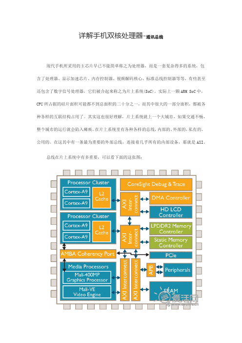
详解手机双核处理器-通讯总线现代手机所采用的主芯片早已不能简单称之为处理器,而是一套复杂得多的系统,包含了处理器、显示加速芯片、内存控制器、视频解码核心、标准总线控制器等等,有些甚至还包含了数字信号处理器,它们被合起来称之为片上系统(SoC)。
实际上一颗ARM SoC中,CPU所占据的硅片面积可能都不到总面积的二十分之一,而其中很大的一部分面积,都被各种各样的互联结构占用了。
其实这也很好理解,片上系统就上一个大城市,如果交通不畅,整个城市的运行就会陷入瘫痪。
在片上系统里有各种各样的总线,内部的、外部的,私有的、公用的。
在这其中有一条最为重要的外部总线,连接着几乎所有的内部设备,那就是AXI。
总线在片上系统中有多重要,可以看下面的这张图:可以看到,几乎所有的内部设备,都通过多层次、多区域的AXI互联接口进行沟通,更重要的是,内存控制器也是通过AXI连接到处理器,这就意味着不论你的内存颗粒或者内存控制器可以提供多大的带宽,处理器能够获得的带宽都直接且仅取决于总线带宽。
因此这个总线的宽度,决定了整个系统内部最大的内存带宽,同时也在某些情况下决定了诸如3D GPU这些对内存带宽需求巨大的模块的性能。
正如城市的发展需要高速交通一样,随着片上系统的复杂化,内部互联的带宽也要求越来越大。
数据总线相当于处理器内部的“高速公路”由于总线方面的信息不属于一般用户所理解的范畴,因此厂家往往也不会对此做出详细的说明,所以每一款芯片究竟总线宽度多少也是不容易查证的。
这点上nVIDIA相对而言做的最好,因为他们曾经直接把AXI总线位宽标在了网页上:32bit,类型为AMBA-3(这个参数在现在的网页上已经找不到了,原因未知)。
这个数字是相当“惊悚”的,因为如果总线宽度真的是32bit,那么意味着Tegra 2的内部总线位宽只是ARM11级别的。
因此nVIDIA 在Tegra 2的内部,很可能采用了与标准ARM不同的总线配置方式,但是不论如何,Tegra 2的总线带宽都是难以置信的小,即便AXI频率达到300甚至400MHz,带宽最多也只能达到Cortex A8的水平。
10GBASE-KR 介绍及仿真优化

Insertion Loss
Insertion Loss Deviation
• The insertion loss deviation is the difference between the insertion loss and the fitted attenuation.
ILD (f) = IL(f) – A(f)
设计关键六:阻抗一致性(案例3)
优化前
优化后
案例分析:一博测试板(案例4)
Insertion Loss测试结果
Return Loss测试结果
案例分析:背板仿真(案例5)
Connector vendor:Tyco Model frequency range: DC to 20 GHz in 50 MHz frequency steps 背板参数: 20层背板5mm厚度 走线最长长度: 9243mil ,最短长度:1150mil。 最短stub在第19层,12mil; 最长stub在第4层,170mil; 以第19层最长线路为例。
阻抗曲线
插损曲线
回损曲线
Drill越小,阻抗越大,插损曲线和回损曲线越好。
设计关键五:背钻评估
• Back_drill
Stub越来越长
背钻评估
• 比较三种情况下插损曲线(SDD21)
红色曲线stub为7mil,黑色曲线stub为40mil,蓝色曲线stub为85mil,根据需要选择一 定的背钻。
10GBASE-KR发展背景
10GBASE-KR简介
• 在背板接口标准中(802.3ap),10G背板目前存在并行和 串行两种版本。并行(10GBASE-KX4)将10G信号拆分为4条 通道,每条通道的速率都是3.125Gb/s(类似于XAUI)。 串行(10GBASE-KR)定义了一条通道,采用64B66B编码方 式,速率为10.3125Gb/s。目前对于总带宽有较高需求或 者需要解决走线密集度过高的背板,许多芯片供应商提供 SerDes芯片均采用10GBASE-KR解决方案。
10GBASE-KR介绍及仿真优化

连接器选择
设计关键四:过孔参数优化
Anti pad大小优化
阻抗曲线
插损曲线
回损曲线
Anti pad越大,阻抗越大,插损曲线和回损曲线越好。
Pad大小优化
阻抗曲线
插损曲线
回损曲线
Pad 越小,阻抗越大,损耗曲线的趋势也基本一致
Drill大小优化
仿真眼图
左边为俯视眼图,右边为3维眼图。
测试波形图
差分输出波形。
测试波形图
测试眼图
差分输出眼图。
Thank you!
• ICR Spec曲线
互连通道优化案例
设计关键一:板材选择
主流高速板材特性
设计关键二:叠层设计(案例1)
叠层设计(案例2)
设计关键三:连接器选择
• 目前,背板连接器的厂商比较多,比如TYCO、ERNI、Molex、 Foxconn等等。但是质量参差不齐,连接器的选择就成为了 设计成功的关键步骤。
10GBASE-KR应用
• 10GBASE-KR主要用于背板应用,如刀片服务器、路由器和 交换机的集群线路卡,所以又称之为“背板以太网”。
10GBASE-KR
速率 基带 背板 64B66B编码
基于ATCA架构的10GB-KR信号示意图
插卡
插卡
插卡
10GBASE-KR 背板
10GBASE-KR
PHY SFI/XFI
10GBASE-KR发展背景
10GBASE-KR简介
• 在背板接口标准中(802.3ap),10G背板目前存在并行和 串行两种版本。并行(10GBASE-KX4)将10G信号拆分为4条 通道,每条通道的速率都是3.125Gb/s(类似于XAUI)。 串行(10GBASE-KR)定义了一条通道,采用64B66B编码方 式,速率为10.3125Gb/s。目前对于总带宽有较高需求或 者需要解决走线密集度过高的背板,许多芯片供应商提供 SerDes芯片均采用10GBASE-KR解决方案。
XGMII-XLGMII-CGMII-XAUI-XLAUI-CAUI高速总线简介

XGMII/XLGMII/CGMII/XAUI/XLAUI/CAUI高速总线简介在以太网标准中,MAC层与PHY层之间的10Gbps/40Gbps/100Gbps速率等级所对应的接口分别为XGMII/XLGMII/CGMII,由于XGMII/XLGMII/CGMII是并行总线,而且采用的是单端信号,HSTL电平,最大传输距离只有不到7cm。
所以在实际应用中,XGMII/XLGMII/CGMII基本上被XAUI/XLAUI/CAUI替代。
XAUI/XLAUI是四通道串行总线,采用的差分信号,CML逻辑传输,并且进行了扰码,大大增强了信号的抗扰性能,使得信号的有效传输距离增加到50cm。
XGMII接口概述:TXD[31:0]:数据发送通道,32位并行数据。
RXD[31:0]:数据接收通道,32位并行数据。
TXC[3:0]:发送通道控制信号,TXC=0时,表示TXD上传输的是数据;TXC=1时,表示TXD 上传输的是控制字符。
TXC[3:0]分别对应TXD[31:24], TXD[23:16], TXD[15:8], TXD[7:0]。
RXC[3:0]:接收通道控制信号,RXC=0时,表示RXD上传输的是数据;RXC=1时,表示RXD 上传输的是控制字符。
RXC[3:0]分别对应RXD[31:24], RXD[23:16], RXD[15:8], RXD[7:0]。
TX_CLK:TXD和TXC的参考时钟,时钟频率156.25MHz,在时钟信号的上升沿和下降沿都采样数据。
156.25MHz * 2 * 32 = 10Gbps 。
RX_CLK:RXD和RXC的参考时钟,时钟频率156.25MHz,在时钟信号的上升沿和下降沿都采样数据。
XGMII接口共74根连线,单端信号,采用HSTL/SSTL_2逻辑,端口电压1.5V/2.5V,由于SSTL_2的端口电压高,功耗大,现在已很少使用。
HSTL即High Speed Transceiver Logic,高速发送逻辑的意思。
AXI总线介绍

主机 主机
保护类型。 写地址有效。 1 = 地址和控制信息有效 0 = 地址和控制信息无效
ห้องสมุดไป่ตู้
这个信号会一直保持,直到AWREADY变为高。
AWREADY 设备 写地址准备好。这个信号用来指明设备已经准备好接 受地址和控制信息了。 1 = 设备准备好 0 = 设备没准备好
11
AXI信号(3)
Write data channel :
30
Burst 方式
1、固定式突发读写是指地址是固定的,每一次传输的地址都不变。这样的突发式读写是 重复的对一个相同的位置进行存取。例如FIFO。 2、增值式突发读写是指每一次读写的地址都比上一次的地址增加一个固定的值。 包装式突发读写跟增值式突发读写类似。包装式突发读写的地址是包数据的低地址当到 达一个包边界。 3、包装式突发读写有两个限制: 1起始地址必须以传输的size对齐。 2突发式读写的长度必须是2、4、8或者16
信号 WID[3:0] WDATA[31:0] WSTRB[3:0] 源 主机 主机 主机 描述 写ID tag,WID的值必须与AWID的值匹配 写的数据。 写阀门。WSTRB[n]标示的区间为WDATA[(8*n)+7:(8*n)]
WLAST WVALID
主机 主机
写的最后一个数据。 写有效 1 = 写数据和阀门有效 0 = 写数据和阀门无效
WREADY
设备
写就绪。指明设备已经准备好接受数据了 1 = 设备就绪 0 = 设备未就绪
12
AXI信号(4)
Write response channel :
信号 BID[3:0] BRESP[1:0] 源 设备 设备 描述 响应ID , 这个数值必须与AWID的数值匹配。 写响应。这个信号指明写事务的状态。可能有的响应:OKAY、 EXOKAY、SLVERR、DECERR。
各类总线传输速率
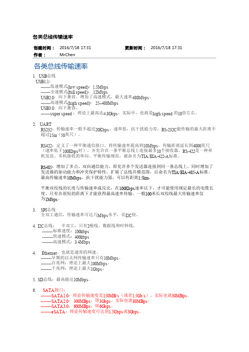
各类总线传输速率创建时间:2016/7/18 17:31更新时间:2016/7/18 17:31作者:MrChen各类总线传输速率1. USB总线USB1.1:-------低速模式(low speed):1.5Mbps-------全速模式(full speed): 12MbpsUSB2.0:向下兼容。
增加了高速模式,最大速率480Mbps。
-------高速模式(high speed): 25~480MbpsUSB3.0:向下兼容。
-------super speed :理论上最高达4.8Gbps,实际中,也就是high speed 的10倍左右。
2. UARTRS232:传输速率一般不超过20Kbps,速率低,抗干扰能力差,RS-232C能传输的最大距离不超过15m(50英尺)。
RS422:定义了一种平衡通信接口,将传输速率提高到10Mbps,传输距离延长到4000英尺(速率低于100Kbps时),并允许在一条平衡总线上连接最多10个接收器。
RS-422是一种单机发送、多机接收的单向、平衡传输规范,被命名为TIA/EIA-422-A标准。
RS485:增加了多点、双向通信能力,即允许多个发送器连接到同一条总线上,同时增加了发送器的驱动能力和冲突保护特性,扩展了总线共模范围,后命名为TIA/EIA-485-A标准。
最高传输速率10Mbps,抗干扰能力强,可以传距离1.5km。
平衡双绞线的长度与传输速率成反比,在100Kbps速率以下,才可能使用规定最长的电缆长度。
只有在很短的距离下才能获得最高速率传输。
一般100米长双绞线最大传输速率仅为1Mbps。
3. SPI总线全双工通信,传输速率可达几Mbps水平,比I2C快。
4. I2C总线: 半双工,只有2根线。
数据线和时钟线。
--------标准速度:100kbps--------快速模式:400kbps--------高速模式:3.4Mbps4. Ethernet,也就是通常的网速。
backplane

随着电子通信技术的高速发展,目前的总线带宽已经发展到10Gbps/40Gbps,正在100Gbps带宽迈进。
XAUI/XLAUI、Interlaken、SPI4.1/SPI4.2、SPI5/SFI5等高速总线虽然能满足10Gbps/40Gbps带宽的需求,但这些总线都是板内总线,传输距离非常有限,一般局限在50cm以内。
对于ATCA架构的高性能计算平台,由于需要很长的背板走线,这些总线已不能满足要求,为此,IEEE颁布了802.3ap 标准,里面提出了Backplane Ethernet概念,提供10GBASE-KR, 40GBASE-KR4两种总线方案,最大传输距离可达1m (40 inch)。
Backplane Ethernet结构如下图所示。
缩略语解释:AN=AUTO-NEGOTIATION,自协商GMII=GIGABIT MEDIA INDEPENDENT INTERFACE,吉比特媒体独立接口MDI=MEDIUM DEPENDENT INTERFACE,媒体相关接口PCS=PHYSICAL CODING SUBLAYER,物理编码子层FEC=FORWARD ERROR CORRECTION,前向纠错PHY=PHYSICAL LAYER DEVICE,物理层设备PMA=PHYSICAL MEDIUM ATTACHMENT,物理媒体附属层PMD=PHYSICAL MEDIUM DEPENDENT,物理媒体相关层XGMII=10 GIGABIT MEDIA INDEPENDENT INTERFACE,10吉比特媒体独立接口♦典型用法在连接背板的接口板上,通过PHY芯片将10GBASE-KR/40GBASE-KR4转换为XFI或SFI总线后接SFP+或XFP光模块,目前具备该转换功能的PHY芯片有: BCM8707(40GBASE-KR4→XAUI)+BCM8747(XAUI→SFI)BCM8754(XFI→SFI)+MAX3804均衡器,放在接收端BCM84064(40GBASE-KR4→XFI)PM5422(40GBASE-KR4→XFI)NLP3233用法示意图如下所示(基于ATCA架构)光模块的种类:GBIC:Gigabit Interface Converter,个头比较大,直接焊接在PCB上,支持速率为1Gbps,目前已经被SFP替代。
(完整版)BackplaneEthernet简介
随着电子通信技术的高速发展,目前的总线带宽已经发展到10Gbps/40Gbps,正在100Gbps带宽迈进。
XAUI/XLAUI、Interlaken、SPI4.1/SPI4.2、SPI5/SFI5等高速总线虽然能满足10Gbps/40Gbps带宽的需求,但这些总线都是板内总线,传输距离非常有限,一般局限在50cm以内。
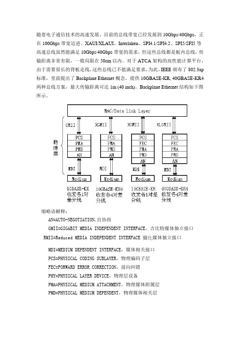
对于ATCA架构的高性能计算平台,由于需要很长的背板走线,这些总线已不能满足要求,为此,IEEE颁布了802.3ap 标准,里面提出了Backplane Ethernet概念,提供10GBASE-KR, 40GBASE-KR4两种总线方案,最大传输距离可达1m (40 inch)。
Backplane Ethernet结构如下图所示。
缩略语解释:AN=AUTO-NEGOTIATION,自协商GMII=GIGABIT MEDIA INDEPENDENT INTERFACE,吉比特媒体独立接口RMII=Reduced MEDIA INDEPENDENT INTERFACE 簡化媒体独立接口 MDI=MEDIUM DEPENDENT INTERFACE,媒体相关接口PCS=PHYSICAL CODING SUBLAYER,物理编码子层FEC=FORWARD ERROR CORRECTION,前向纠错PHY=PHYSICAL LAYER DEVICE,物理层设备PMA=PHYSICAL MEDIUM ATTACHMENT,物理媒体附属层PMD=PHYSICAL MEDIUM DEPENDENT,物理媒体相关层XGMII=10 GIGABIT MEDIA INDEPENDENT INTERFACE,10吉比特媒体独立接口SGMII=Serial Gigabit media independent 是PHY與MAC之間的接口♦典型用法在连接背板的接口板上,通过PHY芯片将10GBASE-KR/40GBASE-KR4转换为XFI或SFI总线后接SFP+或XFP光模块,目前具备该转换功能的PHY芯片有: BCM8707(40GBASE-KR4→XAUI)+BCM8747(XAUI→SFI)BCM8754(XFI→SFI)+MAX3804均衡器,放在接收端BCM84064(40GBASE-KR4→XFI)PM5422(40GBASE-KR4→XFI)NLP3233用法示意图如下所示(基于ATCA架构)光模块的种类:GBIC:Gigabit Interface Converter,个头比较大,直接焊接在PCB上,支持速率为1Gbps,目前已经被SFP替代。
网络MII接口与详解
硬件部分1MII接口简介:MII是英文Medium Independent Interface的缩写,翻译成中文是“介质独立接口”,该接口一般应用于MAC层和PHY层之间的以太网数据传输,也可叫数据接口。
(MAC 与PHY间的管理接口一般是MDIO)MII接口的类型有很多,常用的有MII、RMII、SMII、SSMII、SSSMII、GMII、RGMII、SGMII、TBI、RTBI、XGMII、XAUI、XLAUI等。
下面对它们进行一一介绍。
MII接口TXD(Transmit Data)[3:0]:数据发送信号,共4根信号线;RXD(Receive Data)[3:0]:数据接收信号,共4根信号线;TX_ER(Transmit Error):发送数据错误提示信号,同步于TX_CLK,高电平有效,表示TX_ER有效期内传输的数据无效。
对于10Mbps速率下,TX_ER不起作用;RX_ER(Receive Error):接收数据错误提示信号,同步于RX_CLK,高电平有效,表示RX_ER有效期内传输的数据无效。
对于10Mbps速率下,RX_ER不起作用;TX_EN(Transmit Enable):发送使能信号,只有在TX_EN有效期内传的数据才有效;RX_DV(Reveive Data Valid):接收数据有效信号,作用类型于发送通道的TX_EN;TX_CLK:发送参考时钟,100Mbps速率下,时钟频率为25MHz,10Mbps速率下,时钟频率为。
注意,TX_CLK时钟的方向是从PHY侧指向MAC侧的,因此此时钟是由PHY提供的。
RX_CLK:接收数据参考时钟,100Mbps速率下,时钟频率为25MHz,10Mbps速率下,时钟频率为。
RX_CLK也是由PHY侧提供的。
CRS:Carrier Sense,载波侦测信号,不需要同步于参考时钟,只要有数据传输,CRS 就有效,另外,CRS只有PHY在半双工模式下有效;COL:Collision Detectd,冲突检测信号,不需要同步于参考时钟,只有PHY在半双工模式下有效。
Microchip RTG4 FPGA XAUI 高速序列接口应用说明书
RTG4™ Field Programmable Gate Arrays (FPGAs) have embedded high-speed SerDes blocks that can handle data rates from 1 Gbps to5 Gbps. The SerDes module integrates several functional blocks to support multiple high-speed serial protocols within the FPGA. 10 Gigabit Attachment Unit Interface (XAUI) is a standard for extending the 10 Gb Media Independent Interface (XGMII) between the Media Access Control (MAC) and PHY layer of 10 Gb Ethernet (10GbE). RTG4 high-speed serial block implements hardened XAUI.This document contains information with respect to the software simulations of the XAUI protocol.RTG4 SerDes XAUIAN4948AN4948Table of Contents Introduction (1)1. Design Requirements (3)2. Prerequisites (4)3. Demo Design (5)3.1. Design Implementation (6)3.2. IP Configuration (6)4. Clocking Structure (9)5. Reset Structure (10)6. Simulating the Design (11)7. Conclusion (14)8. Appendix: Running the TCL Script (15)9. Revision History (16)Microchip FPGA Support (17)Microchip Information (17)The Microchip Website (17)Product Change Notification Service (17)Customer Support (17)Microchip Devices Code Protection Feature (17)Legal Notice (18)Trademarks (18)Quality Management System (19)Worldwide Sales and Service (20)Design Requirements 1. Design Requirements (Ask a Question)The following table lists the software requirements for this demo design.Important: Libero® SmartDesign and configuration screenshots shown in this guide arefor illustration purpose only. Open the Libero design to see the latest updates.2. Prerequisites (Ask a Question)Before you start, perform the following steps:1.Download and install Libero SoC (as indicated in the website for this design) on the host PC fromthe following location: Libero SoC Documentation2.Download the design files from the following link: /en-us/application-notes/an49483. Demo Design (Ask a Question)This demo design demonstrates transmitting Continuous Random Test Pattern (CRPAT) andContinuous Jitter Test Pattern (CJPAT) over the RTG4 high-speed SerDes interface. SerDes isconfigured for3.125 Gbps operational speed.The following figure shows a system block diagram for the design implemented in the RTG4 device.Figure 3-1. SerDes XAUI Demo Design Top-Level Block DiagramThe following are the descriptions of block used in the design:•CRPAT_MEM: This block implements the IEEE® 802.3ae CRPAT and generates a continuous stream of identical patterns, separated by a minimum Inter-Packet Gap (IPG). The CRPAT is intended toprovide broad spectral content and minimal peaking used for the measurement of jitter at eithera component or system level.Each packet in the CRPAT consists of eight octets of PREAMBLE/SFD, followed by 1488 data octets(124 repetitions of the 12-octet modified RPAT sequence), and four CRC octets, followed by aminimum IPG of 12 octets of IDLE.•CJPAT_MEM: This block implements the IEEE 802.3ae CJPAT. The CJPAT is intended to expose a receiver CDR to large instantaneous phase jumps. The pattern alternates repeating low-transitiondensity patterns with repeating high-transition density patterns. The repeating code-groupduration must be longer than the time constants in the receiver clock recovery circuit. Thisassures that the clock phase has followed the systematic pattern jitter and the data samplingcircuitry is exposed to large systematic phase jumps. This stresses the timing margins in thereceived eye.•Pattern selector: This module is used for the selection of either CRPAT or CJPAT to be sent onto the transmitter of XAUI. This selection input is driven from the host terminal through the GUI.•Transmitter: It sends the pattern along with control signals onto the SerDes interface. The data is fed into the transmitter from the pattern selector block. The transmitter sends 64 bits of datasignals onto the TXD interface and eight bits of control signals into the TXC interface of theSerDes.•Receiver: This block checks for corresponding CRPAT or CJPAT sequences depending on the pattern selection done and sent over the SerDes interface. If the received sequence does notmatch with the one transmitted by the transmitter, the receiver indicates an error. The receiveralso implements an error counter, which is incremented for each error in the received pattern.•Debounce: This logic is written for detecting the stable pulse from GUI. On detecting a stable pulse, the logic raises a flag which is used to initiate the XAUI demo.3.1 Design Implementation (Ask a Question)The following figure shows the Libero SoC software design implementation of the SerDes XAUI.Figure 3-2. SerDes XAUI Design3.2 IP Configuration (Ask a Question)The following IPs and macros need to be configured before simulating the demo design:•High-speed serial interface•Clock conditioning circuitry (RTG4FCCCECALIB)3.2.1 High-Speed Serial Interface (Ask a Question)The RTG4 FPGA high-speed SerDes is a hard IP block on chip that supports rates up to 5 Gbps. TheSerDes block offers embedded protocol support for PCIe, SRIO, XAUI, SGMII, EPCS, and so on. Formore information about the SerDes block, see UG0567 RTG4 FPGA High-Speed Serial Interfaces User Guide.In this demo, the SERDESIF_Block block is configured for the XAUI mode, with reference clock from REFCLK0 coming from an external source.Figure 3-3. High-Speed Serial Interface Configurator3.2.2 Clock Conditioning Circuitry (Ask a Question)RTG4FCCCECALIB provides reference clock needed for a clock for the CoreUART, FabUART, and clock for management block in the SerDes XAUI mode. For more information about CCC blocks, seeUG0586: RTG4 Clocking Resources User Guide.Figure 3-4. CCC Configurator4. Clocking Structure (Ask a Question)The on-chip 50 MHz oscillator provides the reference clock to the RTG4FCCCECALIB_C0 block. TheRTG4FCCCECALIB_C0 block provides two clocks: GL0 (50 MHz) and GL1 (20 MHz). The GL0 clockdrives the SerDes block, UART, and Reset Synchronizer blocks. The GL1 clock drives the SerDesblock. The following figure shows the clocking structure of the design. For more information aboutRTG4FCCCECALIB_C0, see UG0590 RTG4 FPGA Clock Conditioning Circuit with PLL Configuration User Guide.Figure 4-1. Clocking Structure5. Reset Structure (Ask a Question)The RTGFCCCECALIB_C0 LOCK signal is provided to UART, SerDes, and XAUI transmitter. The INIT Done signal from SerDes block is then fed to XAUI TX and XAUI RX.Figure 5-1. Reset Structure6. Simulating the Design (Ask a Question)To simulate the core using the testbench, perform the following steps:1.On the Stimulus Hierarchy tab, right-click the testbench, and then click Set as active stimulus,as shown in the following figure.2.Again right-click the testbench, point to Simulate Pre-Synth Design, and then click OpenInteractively. It invokes the Modelsim and Modelsim tool, which takes about approximatelythree to five minutes to complete the simulation.Important: If you do not see the Stimulus Hierarchy tab, navigate to View >Windows menu, and then click Stimulus Hierarchy to make it visible.Figure 6-1. Simulating the DesignFigure 6-2. Simulating the Design - Open InteractivelyThe demo design consists of following signals:•50 MHz and 156.25 MHz clock•Reset•XAUI transmitter signal•XAUI receiver signal•UART signal•SerDes signalWhen the simulation is successful, the waveform window appears as shown in the following figure.Figure 6-3. Simulation Waveform WindowConclusion 7. Conclusion (Ask a Question)This demo described how to simulate the SerDes XAUI IP cores and how to implement the Liberodesign flow using Libero SoC software.Appendix: Running the TCL Script 8. Appendix: Running the TCL Script (Ask a Question)TCL scripts are provided in the design files folder under the TCL_Scripts directory. If required, thedesign flow can be reproduced from Design Implementation till generation of the job file.To run the TCL, perform the following steps:unch the Libero software.2.Select Project > Execute Script.3.Click Browse and select script.TCL from the downloaded TCL_Scripts directory.4.Click Run.After successful execution of TCL script, Libero project is created within the TCL_Scripts directory.For more information about TCL scripts, see rtg4_an4948_v2022p3_df/TCL_Scripts/readme.txt.For more details on TCL commands, see Tcl Commands Reference Guide. Contact MicrochipTechnical Support for any queries encountered while running the TCL script.Revision History 9. Revision History (Ask a Question)The revision history describes the changes that were implemented in the document. The changesare listed by revision, starting with the most current publication.Microchip FPGA products group backs its products with various support services, including Customer Service, Customer Technical Support Center, a website, and worldwide sales offices. Customers are suggested to visit Microchip online resources prior to contacting support as it is very likely that their queries have been already answered.Contact Technical Support Center through the website at /support. Mention the FPGA Device Part number, select appropriate case category, and upload design files while creating a technical support case.Contact Customer Service for non-technical product support, such as product pricing, product upgrades, update information, order status, and authorization.•From North America, call 800.262.1060•From the rest of the world, call 650.318.4460•Fax, from anywhere in the world, 650.318.8044The Microchip Website (Ask a Question)Microchip provides online support via our website at /. This website is used to make files and information easily available to customers. Some of the content available includes:•Product Support – Data sheets and errata, application notes and sample programs, design resources, user’s guides and hardware support documents, latest software releases and archived software•General Technical Support – Frequently Asked Questions (FAQs), technical support requests, online discussion groups, Microchip design partner program member listing•Business of Microchip – Product selector and ordering guides, latest Microchip press releases, listing of seminars and events, listings of Microchip sales offices, distributors and factoryrepresentativesProduct Change Notification Service (Ask a Question)Microchip’s product change notification service helps keep customers current on Microchip products. Subscribers will receive email notification whenever there are changes, updates, revisions or errata related to a specified product family or development tool of interest.To register, go to /pcn and follow the registration instructions.Customer Support (Ask a Question)Users of Microchip products can receive assistance through several channels:•Distributor or Representative•Local Sales Office•Embedded Solutions Engineer (ESE)•Technical SupportCustomers should contact their distributor, representative or ESE for support. Local sales offices are also available to help customers. A listing of sales offices and locations is included in this document. Technical support is available through the website at: /support Microchip Devices Code Protection Feature (Ask a Question)Note the following details of the code protection feature on Microchip products:•Microchip products meet the specifications contained in their particular Microchip Data Sheet.•Microchip believes that its family of products is secure when used in the intended manner, within operating specifications, and under normal conditions.•Microchip values and aggressively protects its intellectual property rights. Attempts to breach the code protection features of Microchip product is strictly prohibited and may violate the Digital Millennium Copyright Act.•Neither Microchip nor any other semiconductor manufacturer can guarantee the security of its code. Code protection does not mean that we are guaranteeing the product is “unbreakable”.Code protection is constantly evolving. Microchip is committed to continuously improving the code protection features of our products.Legal Notice (Ask a Question)This publication and the information herein may be used only with Microchip products, includingto design, test, and integrate Microchip products with your application. Use of this informationin any other manner violates these terms. Information regarding device applications is provided only for your convenience and may be superseded by updates. It is your responsibility to ensure that your application meets with your specifications. Contact your local Microchip sales office for additional support or, obtain additional support at /en-us/support/design-help/ client-support-services.THIS INFORMATION IS PROVIDED BY MICROCHIP "AS IS". MICROCHIP MAKES NO REPRESENTATIONS OR WARRANTIES OF ANY KIND WHETHER EXPRESS OR IMPLIED, WRITTEN OR ORAL, STATUTORY OR OTHERWISE, RELATED TO THE INFORMATION INCLUDING BUT NOT LIMITED TO ANY IMPLIED WARRANTIES OF NON-INFRINGEMENT, MERCHANTABILITY, AND FITNESS FOR A PARTICULAR PURPOSE, OR WARRANTIES RELATED TO ITS CONDITION, QUALITY, OR PERFORMANCE.IN NO EVENT WILL MICROCHIP BE LIABLE FOR ANY INDIRECT, SPECIAL, PUNITIVE, INCIDENTAL, OR CONSEQUENTIAL LOSS, DAMAGE, COST, OR EXPENSE OF ANY KIND WHATSOEVER RELATED TO THE INFORMATION OR ITS USE, HOWEVER CAUSED, EVEN IF MICROCHIP HAS BEEN ADVISED OF THE POSSIBILITY OR THE DAMAGES ARE FORESEEABLE. TO THE FULLEST EXTENT ALLOWED BY LAW, MICROCHIP'S TOTAL LIABILITY ON ALL CLAIMS IN ANY WAY RELATED TO THE INFORMATION ORITS USE WILL NOT EXCEED THE AMOUNT OF FEES, IF ANY, THAT YOU HAVE PAID DIRECTLY TO MICROCHIP FOR THE INFORMATION.Use of Microchip devices in life support and/or safety applications is entirely at the buyer's risk, and the buyer agrees to defend, indemnify and hold harmless Microchip from any and all damages, claims, suits, or expenses resulting from such use. No licenses are conveyed, implicitly or otherwise, under any Microchip intellectual property rights unless otherwise stated.Trademarks (Ask a Question)The Microchip name and logo, the Microchip logo, Adaptec, AVR, AVR logo, AVR Freaks, BesTime, BitCloud, CryptoMemory, CryptoRF, dsPIC, flexPWR, HELDO, IGLOO, JukeBlox, KeeLoq, Kleer, LANCheck, LinkMD, maXStylus, maXTouch, MediaLB, megaAVR, Microsemi, Microsemi logo, MOST, MOST logo, MPLAB, OptoLyzer, PIC, picoPower, PICSTART, PIC32 logo, PolarFire, Prochip Designer, QTouch, SAM-BA, SenGenuity, SpyNIC, SST, SST Logo, SuperFlash, Symmetricom, SyncServer, Tachyon, TimeSource, tinyAVR, UNI/O, Vectron, and XMEGA are registered trademarks of Microchip Technology Incorporated in the U.S.A. and other countries.AgileSwitch, APT, ClockWorks, The Embedded Control Solutions Company, EtherSynch, Flashtec, Hyper Speed Control, HyperLight Load, Libero, motorBench, mTouch, Powermite 3, Precision Edge, ProASIC, ProASIC Plus, ProASIC Plus logo, Quiet- Wire, SmartFusion, SyncWorld, Temux, TimeCesium, TimeHub, TimePictra, TimeProvider, TrueTime, and ZL are registered trademarks of Microchip Technology Incorporated in the U.S.A.Adjacent Key Suppression, AKS, Analog-for-the-Digital Age, Any Capacitor, AnyIn, AnyOut, Augmented Switching, BlueSky, BodyCom, Clockstudio, CodeGuard, CryptoAuthentication, CryptoAutomotive, CryptoCompanion, CryptoController, dsPICDEM, , DynamicAverage Matching, DAM, ECAN, Espresso T1S, EtherGREEN, GridTime, IdealBridge, In-Circuit Serial Programming, ICSP, INICnet, Intelligent Paralleling, IntelliMOS, Inter-Chip Connectivity, JitterBlocker, Knob-on-Display, KoD, maxCrypto, maxView, memBrain, Mindi, MiWi, MPASM, MPF, MPLAB Certified logo, MPLIB, MPLINK, MultiTRAK, NetDetach, Omniscient Code Generation, PICDEM, , PICkit, PICtail, PowerSmart, PureSilicon, QMatrix, REAL ICE, Ripple Blocker, RTAX, RTG4, SAM-ICE, Serial Quad I/O, simpleMAP, SimpliPHY, SmartBuffer, SmartHLS, SMART-I.S., storClad, SQI, SuperSwitcher, SuperSwitcher II, Switchtec, SynchroPHY, Total Endurance, Trusted Time, TSHARC, USBCheck, VariSense, VectorBlox, VeriPHY, ViewSpan, WiperLock, XpressConnect, and ZENA are trademarks of Microchip Technology Incorporated in the U.S.A. and other countries.SQTP is a service mark of Microchip Technology Incorporated in the U.S.A.The Adaptec logo, Frequency on Demand, Silicon Storage Technology, and Symmcom are registered trademarks of Microchip Technology Inc. in other countries.GestIC is a registered trademark of Microchip Technology Germany II GmbH & Co. KG, a subsidiary of Microchip Technology Inc., in other countries.All other trademarks mentioned herein are property of their respective companies.© 2023, Microchip Technology Incorporated and its subsidiaries. All Rights Reserved.ISBN: 978-1-6683-2503-2Quality Management System (Ask a Question)For information regarding Microchip’s Quality Management Systems, please visit/quality.Worldwide Sales and Service。
主板高速串行总线解析与测试需求分析示波器
主板高速串行总线解析与测试需求分析示波器主板一直是高速串行总线云集的重镇,也是高端示波器厂商必争之地。
但作为一般用户极少关注背后的技术,即使是电脑发烧友也很少有人对这些高速串行总线进行深入了解。
本文试图从当今最顶级的芯片组开始,简单说明一下这些芯片组上的高速总线和所要用到的测试设备。
1X58Intel的X58芯片组是如今PC上最高端的芯片组,也是唯一支持IntelI7CPU的芯片组,该芯片组除了集成了最为常见的高速串行总线外,还有一个最大的特大即使支持Intel自身的QPI总线。
I7相对于Intel以往的CPU最大区别是像AMDK8那样集成了内存控制器,并且支持3通道DDR3内存。
X58支持36Lane的PCIEG2,支持CroosFire,通过NVIDIA 的授权可以直接支持SLI。
下面来看看这些高速串行总线的测试要求。
QPIIntel的QuickPathInterface是在I7cpu上首次推出的,采用了类似于PCIE的点对点(peertopeer)传输,替代了以前并行的FSB。
QPI的bitrate有两种一种是4.8Gbps,另一种是6.4Gbps。
对于6.4Gbps的QPI来说,采用32bit传输时,带宽能达到25.6GB/s。
相对于1600MHz的FSB的带宽12.8GB/s来说,带宽提高了一倍。
相对于AMD的HT3.0具有的5.2Gbps的bitrate和32bit传输时的20.8GB/s的带宽亦是胜出。
同时QPI不但可用于CPU和北桥芯片之间的互联,还能用于多核处理器之间的内部互联,以及与内存控制器之间的互联。
由于QPI6.4Gbps的基波是3.2GHz,1.8bitrate是11.52GHz,5次谐波是16GHz,所以要求带宽在16GHz的示波器才能测试,Tektronix和LeCroy都有带宽在16GHz以上的示波器,但LeCroy目前还没有QPI的测试方案,业界也只有Tektronix第一家推出基于示波器的QPI测试解决方案,而Agilent则是推出了比特误码率测试仪J-BERTN4903B。
XFI.SFI_verygood
随着电子通信技术的高速发展,目前的总线带宽已经发展到10Gbps/40Gbps,正在100Gbps带宽迈进。
XAUI/XLAUI、Interlaken、SPI4.1/SPI4.2、SPI5/SFI5等高速总线虽然能满足10Gbps/40Gbps带宽的需求,但这些总线都是板内总线,传输距离非常有限,一般局限在50cm以内。
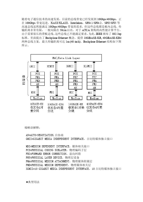
对于ATCA架构的高性能计算平台,由于需要很长的背板走线,这些总线已不能满足要求,为此,IEEE颁布了802.3ap 标准,里面提出了Backplane Ethernet概念,提供10GBASE-KR, 40GBASE-KR4两种总线方案,最大传输距离可达1m (40 inch)。
Backplane Ethernet结构如下图所示。
缩略语解释:AN=AUTO-NEGOTIATION,自协商GMII=GIGABIT MEDIA INDEPENDENT INTERFACE,吉比特媒体独立接口MDI=MEDIUM DEPENDENT INTERFACE,媒体相关接口PCS=PHYSICAL CODING SUBLAYER,物理编码子层FEC=FORWARD ERROR CORRECTION,前向纠错PHY=PHYSICAL LAYER DEVICE,物理层设备PMA=PHYSICAL MEDIUM ATTACHMENT,物理媒体附属层PMD=PHYSICAL MEDIUM DEPENDENT,物理媒体相关层XGMII=10 GIGABIT MEDIA INDEPENDENT INTERFACE,10吉比特媒体独立接口♦典型用法在连接背板的接口板上,通过PHY芯片将10GBASE-KR/40GBASE-KR4转换为XFI或SFI总线后接SFP+或XFP光模块,目前具备该转换功能的PHY芯片有:BCM8707(40GBASE-KR4→XAUI)+BCM8747(XAUI→SFI)BCM8754(XFI→SFI)+MAX3804均衡器,放在接收端BCM84064(40GBASE-KR4→XFI)PM5422(40GBASE-KR4→XFI)NLP3233用法示意图如下所示(基于ATCA架构)光模块的种类:GBIC:Gigabit Interface Converter,个头比较大,直接焊接在PCB上,支持速率为1Gbps,目前已经被SFP替代。
- 1、下载文档前请自行甄别文档内容的完整性,平台不提供额外的编辑、内容补充、找答案等附加服务。
- 2、"仅部分预览"的文档,不可在线预览部分如存在完整性等问题,可反馈申请退款(可完整预览的文档不适用该条件!)。
- 3、如文档侵犯您的权益,请联系客服反馈,我们会尽快为您处理(人工客服工作时间:9:00-18:30)。
XAUI/XLAUI高速总线简介
在以太网标准中,MAC层与PHY层之间的10Gbps/40Gbps/100Gbps速率等级所对应的接口分别为XGMII/XLGMII/CGMII,由于XGMII/XLGMII是并行总线,而且采用的是单端信号,HSTL电平,最大传输距离只有7cm。
所以在实际应用中,XGMII/XLGMII基本上被XAUI/XLAUI替代。
XAUI/XLAUI是四通道串行总线,采用的差分信号,CML逻辑传输,并且进行了扰码,大大增强了信号的抗扰性能,使得信号的有效传输距离增加到50cm。
XAUI/XLAUI总线的的物理结构如下图所示。
XAUI/XLAUI在物理结构上是一样的,收发通道独立,各四对差分信号线。
对于XAUI总线,每对差分线上的数据速率为3.125Gbps,总数据带宽为
12.5Gbps,有效带宽为12.5Gbps*0.8=10Gbps (因为XAUI总线数据在传输前进行了8B/10B变换,编码效率为80%)。
对于XLAUI总线,每对差分线上的数据速率为10.3125Gbps,总数据带宽为41.25Gbps,有效带宽为
41.25Gbps*(64/66)=40Gbps(因为XLAUI总线数据在传输前进行了64B/66B变换,编码效率为96.97%)。
