基于单片机的步进电机控制系统设计外文翻译
基于51单片机步进电机毕业设计外文资料原文与译文
外文原文Stepping motor application and controlStepping motor is an electrical pulse will be converted into angular displacement of the implementing agencies.Put it in simple language-speaking:When the stepper drive pulse signal to a receiver,it drives stepper motor rotation direction by setting a fixed point of view(and the step angel).You can control the number of pulses to control the amount of angular displacement,so as to achieve the purpose of accurate positioning;At the same time,you can by controlling the pulse frequency to control the motor rotation speed and acceleration,so as to achieve the purpose of speed.Stepping motor directly from the AC-DC power supply,and must use special equipment-stepper motor drive. Stepping motor drive system performance,in addition to their own performance with the motor on the outside.but also to a large extent depend on the drive is good or bad.A typical stepper motor drivesystem is operated by the stepper motor controller,stepper motor drives and stepper motor body is composed of therr parts. Stepping motor controller stepper pulse and direction signal,each made of a pulse,stepper motor-driven stepper motor drives a rotor rotating step angle,that is,step-by=step further.High or low speed stepper motor,or speed,or deceleration,start or stop pulses are entirely dependent on whether the level or frequency.Decide the direction of the signal controller stepper motor clockwise or counterclockwise rotation. Typically,the stepper motor drive circuit from the logic control,power driver circuit,protection circuit and power components. Stepping motor drive controller,once received from the direction of the signal and step pulse,the control circuit on a pre-determined way of the electrical power-phase stepper motor drive controller,once received from the direction of the signal and step pulse,the control circuit on a pre-determined way of the electrical power=phase stepper motor excitation windings of the conduction or cut-off signal.Control circuit output signal power amplifier,which is stepper motor driven power drive part.Power stepper motor drive circuit to control the input current winding to form a space for rotating magnetic filed excitation,the rotor-driven movement.Protection circuit in the event of short circuit,overload,overheating,such as failure to stop the rapid and motor.Motor is usually for the permanent rotor,when the current flows through the stator windings,the stator windings produce a magnetic field vector.The magnetic field will lead to a rotor angle of rotation,making a pair of rotor and stator magnetic field direction of the magnetic field direction.When the stator rotating magnetic field vector from a different angle.Also as the rotor magnetic field to a point of view,An electrical pulse for each input,the motor rotation angle step,Tts output and input of the angular displacement is proportional to the pulses,with pulse frequency proportional to speed.Power to change the order of winding,the electrical will be reversed.We can,therefore,control the pulse number,frequency and electrical power windings of each phase to control the order of rotation of stepper motor.Stepping motor types:Permanent magnet(PM).Magnetic generally two-phase stepper,torque and are smaller ab=nd generally stepping angle of 7.5 degrees or 15 degrees;put more wind for air-conditioning. Reactive (VR),the domestic general called BF,have a common three-phase reaction,step angle of 1.5 degrees;also have five-phase reaction.Noise,no torque has been set at a large number of out.Hybrid(HB),conmmon two-phase hybrid,five-phase hybrid,therr-phase hybrid,four-phasehybrid,two-phase can be common with the four-phase drive,five-phase ,three-phase must be used with their drives;Two-phase, four-phase hybrid step angle is 1.8 degrees more than a small size,great distance,and low noise;Five-phase hybrid stepping motor is generally 0.72,the motor step angle small,high resolution,but the complexity of drive circuits,wiring problems,such as the 5-phase system of 10 lines.Three-phase hybrid stepping motor step angle of 1.2 degrees,but according to the use of 1.8 degrees,the three-phase hybrid more pole will help electric folder symmetric angle,it can be more than two-phase,five-phase high accuracy,the error even smaller,run more smoothly. Stepper motor to maintain torque:stepper motor power means no rotation,the stator locked rotoe torque.It is a stepper motor,one of the most important parameters,usually in the low-speed stepper motor torque at the time of close to maintain the torque.As the stepper motor output torque increases with the speed of constant attention,the output power also increases with the speed of change,so as to maintain torque on the stepper motor to measure the parameters of one of the most important.For example,when people say that the stepper motor 2N.m,in the absence of special circumstances that means for maintaining the torque of the stepper motor 2N.m.Precision stepper motoes:stepper motor step angle accuracy of 3-5%,not cumulative. Stepper motor to allow the minimum amount of surface temperature: Stepper motor causes the motor remperature is too high the first magnetic demagnetization,resulting in loss of torque dowm even further,so the motor surface temperature should be the maximum allowed depending in the motor demagnetization of magnetic material pints; enerally speaking,the magnetic demagnetization points are above 130 degrees Clesius,and some even as high as 200degrees Celsius,so the stepper motor surface temperature of 80-90 degrees Celsius is normal. Start frequency of no-load:the stepper motor in case of no-load to the normal start of the pulse frequency,if the pulse frequency is higher than the value of motor does not start,possible to lose steps or blocking.In the case of the load,start frequency should be to accelerate the process,that is ,the lower frequency to start,and then rose to a certain acceleration of the desired frequency (motor speed from low rise to high-speed).Step angle:that is to send a pulse,the electrical angle corresponding to rotation.Torque positioning: positioning torque stepper motor does not refer to the case of electricity,locked rotor torque stator.Operating frequency:step-by-step stpper motor can run without losing thehighest frequency. Subdivision Drive: stepper motor drives the main aim is to weaken or eliminate low-frequency vibration of the stepper motor to improve the accuracy of the motor running.Reduce noise.If the step angle is 1.8 degrees(full step) the two-phase hybrid stepping motor,if the breakdown of the breakdown of the number of drives for the 8,then the operation of the electrical pulse for each resolution of 0.072 degrees,the precision of motor can reach or close to 0.225 degrees,also depends on the breakdown of the breakdown of the drive current control accuracy and other factors,the breakdown of the number of the more difficult the greater the precision of control.中文步进电机应用和控制步进电机是将电脉冲转换成角位移的执行机构。
步进电机及单片机英文文献及翻译
外文文献:Knowledge of the stepper motorWhat is a stepper motor:Stepper motor is a kind of electrical pulses into angular displacement of the implementing agency. Popular little lesson: When the driver receives a step pulse signal, it will drive a stepper motor to set the direction of rotation at a fixed angle (and the step angle). You can control the number of pulses to control the angular displacement, so as to achieve accurate positioning purposes; the same time you can control the pulse frequency to control the motor rotation speed and acceleration, to achieve speed control purposes.What kinds of stepper motor sub-:In three stepper motors: permanent magnet (PM), reactive (VR) and hybrid (HB) permanent magnet stepper usually two-phase, torque, and smaller, step angle of 7.5 degrees or the general 15 degrees; reaction step is generally three-phase, can achieve high torque output, step angle of 1.5 degrees is generally, but the noise and vibration are large. 80 countries in Europe and America have been eliminated; hybrid stepper is a mix of permanent magnet and reactive advantages. It consists of two phases and the five-phase: two-phase step angle of 1.8 degrees while the general five-phase step angle of 0.72 degrees generally. The most widely used Stepper Motor.What is to keep the torque (HOLDING TORQUE)How much precision stepper motor? Whether the cumulative:The general accuracy of the stepper motor step angle of 3-5%, and not cumulative. Stepper motor to allow the minimum amount of surface temperatureStepper motor to allow the minimum amount of surface temperature:Stepper motor causes the motor temperature is too high the first magnetic demagnetization, resulting in loss of torque down even further, so the motor surface temperature should be the maximum allowed depending on the motor demagnetization of magnetic material points; Generally speaking, the magnetic demagnetizationpoints are above 130 degrees Celsius, and some even as high as 200 degrees Celsius, so the stepper motor surface temperature of 80-90 degrees Celsius is normal.How to determine the stepper motor driver DC power supply:A. Determination of the voltageHybrid stepping motor driver power supply voltage is generally a wide range (such as the IM483 supply voltage of 12 ~ 48VDC), the supply voltage is usually based on the work of the motor speed and response to the request to choose. If the motor operating speed higher or faster response to the request, then the voltage value is high, but note that the ripple voltage can not exceed the maximum input voltage of the drive, or it may damage the drive.B. Determination of CurrentPower supply current is generally based on the output phase current drive I to determine. If a linear power supply, power supply current is generally preferable 1.1 to 1.3 times the I; if we adopt the switching power supply, power supply current is generally preferable to I, 1.5 to 2.0 times.The main characteristics of stepping motor:A stepper motor drive can be added operate pulse drive signal must be no pulse when the stepper motor at rest, such asIf adding the appropriate pulse signal, it will to a certain angle (called the step angle) rotation. Rotation speed and pulse frequency is proportional to.2 Dragon step angle stepper motor version is 7.5 degrees, 360 degrees around, takes 48 pulses to complete.3 stepper motor has instant start and rapid cessation of superior characteristics.Change the pulse of the order of 4, you can easily change the direction of rotation. Therefore, the current printers, plotters, robotics, and so devices are the core of the stepper motor as the driving force.Stepper motor control exampleWe use four-phase unipolar stepper motor as an example. The structure shown in Figure 1:Four four-phase winding leads (as opposed to phase A1 A2 B1 phase phase B2) and two public lines (to the power of positive). The windings of one phase to the power of the ground. So that the windings will be inspired. We use four-phase eight-beat control, ie, 1 phase 2 phase alternating tur n, would enhance resolution. 0.9 ° per step can be transferred to control the motor excitation is transferred in order as follows:If the requirements of motor reversal, the transmission excitation signal can be reversed. 2 control schemeControl system block diagram is as followsThe program uses AT89S51 as the main control device. It is compatible with the AT89C51, but also increased the SPI interface and the watchdog module, which not only makes the debugging process becomes easy and also more stable. The microcontroller in the program mainly for field signal acquisition and operation of the stepper motor to calculate the direction and speed information. Then sent to the CPLD.CPLD with EPM7128SLC84-15, EPM7128 programmable logic device of large-scale, for the ALTERA company's MAX7000 family. High impedance, electrically erasable and other characteristics, can be used for the 2500 unit, the working voltage of +5 V. CPLD receives information sent from the microcontroller after converted to the corresponding control signal output to the stepper motor drive. Put the control signal drives the motor windings after the input, to achieve effective control of the motor. 2.1 The hardware structure of the motor driveMotor drive using the following circuit:R1-R8 in which the resistance value of 320Ω. R9-R12 resistance value 2.2KΩ. Q1-Q4 as Darlington D401A, Q5-Q8 for the S8550. J1, J2 and the stepper motor connected to the six-lead。
基于单片机的步进电机控制系统

基于单片机的步进电机控制系统摘要:传统步进电机控制系统往往采用硬件电路构成的控制器,电路复杂不易实现。
本文研究了基于单片机的步进电机控制方法,电路简单,实现了软件对电机进行各种操作,既降低了硬件成本又提高了控制的灵活性。
abstract: the traditional stepper motor control system is often used controller with hardware circuit which is not easy to achieve due to complex circuit. this paper studied stepper motor control method based on scm whose circuit is simple. it achieves various operations to motor of software,reduces hardware cost and increases the flexibility of the control.关键词:单片机;步进电机key words: scm;stepper motor中图分类号:tp31 文献标识码:a 文章编号:1006-4311(2013)05-0185-020 引言随着微电子技术和计算机技术的发展,步进电机广泛应用于电动玩具、打印机等消费类产品以及数控车床、医疗器械等机电类产品中,研究步进电机的控制系统,对提高控制的精度和响应速度以及节约成本方面都具有重要意义。
1 步进电机控制系统整体设计步进电机控制系统能够实现对步进电机转速、旋转时间(0s-9999s)的任意设定,并且支持正反转两种旋转方式。
同时具有简单的人机交互界面,是人们更加容易操作。
本系统由硬件系统和软件系统两部分组成。
硬件设计由单片机最小系统、电源模块、键盘控制模块、显示模块组成;软件设计包括键盘控制、步进电机脉冲、显示模块、以及转速计算模块的控制程序,最终实现对步进电机转动方向、转动时间的控制,并将步进电机的的转动速度、转动剩余时间显示在显示模块上面,如图1所示。
单片机控制步进电机外文文献翻译

单片机控制步进电机外文原文Stepping motor application and control stepper motor is an electrical pulse will be converted into angular displacement of the implementing agencies. Put it in simple language-speaking: When the stepper drive pulse signal to a receiver, it drives stepper motor rotation direction by setting a fixed point of view (and the step angle). You can control the number of pulses to control the amount of angular displacement, so as to achieve the purpose of accurate positioning; At the same time, you can by controlling the pulse frequency to control the motor rotation speed and acceleration,so as to achieve the purpose of speed.Stepper motor directly from the AC-DC power supply,and must use special equipment - stepper motor drive. Stepper motor drive system performance, in addition to their own performance with the motor on the outside, but also to a large extent depend on the drive is good or bad. A typical stepper motor drive system is operated by the stepper motor controller, stepper motor drives and stepper motor body is composed of three parts. Stepper motor controller stepper pulse and direction signal, each made of a pulse, stepper motor-driven stepper motor drives a rotor rotating step angle, that is, step-by-step further. High or low speed stepper motor, or speed, or deceleration, start or stop pulses are entirely dependent on whether the level or frequency.Decide the direction of the signal controller stepper motor clockwise or counterclockwise rotation. Typically, the stepper motor drive circuit from the logic control, power driver circuit, protection circuit and power components.Stepper motor drive controller, once received from the direction of the signal and step pulse, the control circuit on a pre-determined way of the electrical power-phase stepper motor excitation windings of the conduction or cut-off signal. Control circuit output signal power is low,can not provide the necessary stepping motor output power, the need for power amplifier, which is stepper motor driven power drive part. Power stepper motor drive circuit to control the input current winding to form a space for rotating magnetic field excitation, the rotor-driven movement.Protection circuit in the event of shortcircuit, overload, overheating, such as failure to stop the rapid drive and motor. Motor is usually for the permanent magnet rotor, when the current flows throughthe stator windings, the stator windings produce a magnetic field vector.The magnetic field will lead to a rotor angle of rotation, making a pair of rotor and stator magnetic field direction of the magnetic field direction. When the stator rotating magnetic field vector from a different angle. Also as the rotor magnetic field to a point of view. An electrical pulse for each input, the motor rotation angle step. Its output and input of the angular displacement is proportional to the pulses, with pulse frequency proportional to speed. Power to change the order of winding,the electrical will be reversed. We can, therefore, control the pulse number, frequency and electrical power windings of each phase to control the order of rotation of stepper motor.Stepper motor types:Permanent magnet (PM). Magnetic generally two-phase stepper, torque and are smaller and generally stepping angle of 7.5 degrees or 15 degrees; put more wind for air-conditioning.Reactive(VR), the domestic general called BF, have a common three-phase reaction, step angle of 1.5 degrees; also have five-phase reaction. Noise, no torque has been set at a large number of out.Hybrid (HB), common two-phase hybrid, five-phase hybrid, three-phase hybrid, four-phase hybrid, two-phase can be common with the four-phase drive, five-phase three-phase must be used with their drives;Two-phase, four-phase hybrid step angle is 1.8 degrees more than a small size, great distance,and low noise;Five-phase hybrid stepping motor is generally 0.72, the motor step angle small, high resolution, but the complexity of drive circuits, wiring problems, such as the 5- phase system of 10 lines.Three-phase hybrid stepping motor step angle of 1.2 degrees, but according to the use of 1.8 degrees, the three-phase hybrid stepping motor has a two-phase mixed than the five-phase hybrid more pole will help electric folder symmetric angle, it can be more than two-phase, five-phase high accuracy, the error even smaller, run moresmoothly.Stepper motor to maintain torque: stepper motor power means no rotation, the stator locked rotor torque. It is a stepper motor, one of the most important parameters, usually in the low-speed stepper motor torque at the time of close to maintain the torque. As the stepper motor output torque increases with the speed of constant attenuation, the output power also increases with the speed of change,so as to maintain torque on the stepper motor to measure the parameters of one of the most important. For example, when people say that the stepper motor 2N.m, in the absence of special circumstances that means for maintaining the torque of the stepper motor 2N.m.Precision stepper motors:stepper motor step angle accuracy of 3-5%, not cumulative.Stepper motor to allow the minimum amount of surface temperature:Stepper motor causes the motor temperature is too high the first magnetic demagnetization, resulting in loss of torque down even further, so the motor surface temperature should be the maximum allowed depending on the motor demagnetization of magnetic material points; Generally speaking,the magnetic demagnetization points are above 130 degrees Celsius, and some even as high as 200 degrees Celsius, so the stepper motor surface temperature of 80-90 degrees Celsius is normal.Start frequency of no-load: the stepper motor in case of no-load to the normal start of the pulse frequency, if the pulse frequency is higher than the value of motor does not start, possible to lose steps or blocking.In the case of the load, start frequency should be lower. If you want to achieve high-speed rotation motor, pulse frequency should be to accelerate the process, that is, the lower frequency to start, and then rose to a certain acceleration of the desired frequency (motor speed from low rise to high-speed).Step angle:that is to send a pulse,the electrical angle corresponding to rotation.Torque positioning: positioning torque stepper motor does not refer to the case of electricity,locked rotor torque stator.Operating frequency:step-by-step stepper motor can run without losing thehighest frequency.Subdivision Drive: stepper motor drives the main aim is to weaken or eliminate low-frequency vibration of the stepper motor to improve the accuracy of the motor running. Reduce noise. If the step angle is 1.8 °(full step) the two-phase hybrid stepping motor, if the breakdown of the breakdown of the number of drives for the 8, then the operation of the electrical pulse for each resolution of 0.072 °, the precision of motor can reach or close to 0.225 °, also depends on the breakdown of the breakdown of the drive current control accuracy and other factors, the breakdown of the number of the more difficult the greater the precision of control.How to determine the stepper motor driver DC power supply:A.Determination of the voltage: Hybrid stepping motor driver power supply voltage is generally a wide range (such as the IM483 supply voltage of 12 ~ 48VDC), the supply voltage is usually based on the work of the motor speed and response to the request to choose.If the motor operating speed higher or faster response to the request, then the voltage value is high, but note that the ripple voltage can not exceed the maximum input voltage of the drive,or it may damage the drive.B.Determination of CurrentPower supply current is generally based on the output phase current drive I to determine. If a linear power supply, power supply current is generally preferable 1.1 to 1.3 times the I; if we adopt the switching power supply, power supply current is generally preferable to I,1.5to 2.0 times.The main characteristics of stepping motor:1. A stepper motor drive can be added operate pulse drive signal must be no pulse when the stepper motor at rest, such as If adding the appropriate pulse signal, it will to a certain angle (called the step angle) rotation. Rotation speed and pulse frequency is proportional to.2.permanent magnet step angle stepper motor version is 7.5 degrees, 360 degrees around, takes48 pulses to complete.3.stepper motor has instant start and rapid cessation of superior characteristics. Change the order of the pulse4.you can easily change the direction of rotation.Therefore, the current printers, plotters, robotics, and so devices are the core of the stepper motor as the driving force.Stepper motors have the following benefits: (1)Low cost (2)Ruggedness (3)Simplicity in construction (4)High reliability(5)No maintenance(6)Wide acceptance(7)No tweaking to stabilize (8)No feedback components are neededThey work in just about any environment Inherently more failsafe than servo motors. There isvirtually no conceivable failure within the stepper drive module that could cause the motor to run away. Stepper motors are simple to drive and control in an open-loop configuration. They only require four leads. They provide excellent torque at low speeds, up to 5 times the continuous torque of a brush motor of the same frame size or double the torque of the equivalent brushless motor. This often eliminates the need for a gearbox. A stepper-driven-system is inherently stiff, with known limits to the dynamic position error.Stepper Motor Disadvantages:Stepper motors have the following disadvantages:1.Resonance effects and relatively long settling times.1.Rough performance at low speed unless a microstep drive is used.2.Liability to undetected position loss as a result of operating open-loop .4.They consume current regardless of load conditions and therefore tend to run hot5.Losses at speed are relatively high and can cause excessive heating, and they are frequently noisy (especially at high speeds).1.They can exhibit lag-lead oscillation, which is difficult to damp.There is a limit to their available size, and positioning accuracy relies on the mechanics(e.g., ballscrew accuracy).Many of these drawbacks can be overcome by the use of a closed-loop control scheme.外文资料翻译译文步进电机应用和控制步进电机是将电脉冲转换成角位移的执行机构。
外文翻译--步进电机运动控制系统设计

密级分类号编号成绩本科生毕业设计 (论文)外文翻译原文标题Stepper Motor Motion Control System Design 译文标题步进电机运动控制系统设计作者所在系别机械工程系作者所在专业机械设计制造及其自动化作者所在班级作者姓名作者学号指导教师姓名指导教师职称完成时间2012 年 2 月的个数严格成正比,在时间上与输入脉冲同步,因此只要控制输入脉冲的数量、频率及电动机绕组通电的相序,便可获得所需的转角、转速及转动方向。
在没有脉冲输入时,在绕组电源的激励下气隙磁场能使转子保持原有位置处于定位状态。
因此非常适合于单片机控制。
步进电机还具有快速启动、精确步进和定位等特点,因而在数控机床,绘图仪,打印机以及光学仪器中得到广泛的应用。
步进电动机已成为除直流电动机和交流电动机以外的第三类电动机。
传统电动机作为机电能量转换装置,在人类的生产和生活进入电气化过程中起着关键的作用。
步进电机可以作为一种控制用的特种电机,利用其没有积累误差(精度为100%)的特点,广泛应用于各种开环控制。
现在比较常用的步进电机包括反应式步进电机(VR)、永磁式步进电机(PM)、混合式步进电机(HB)和单相式步进电机等。
一步进电机的工作原理步进电机是一种用电脉冲进行控制 ,将电脉冲信号转换成相位移的电机 ,其机械位移和转速分别与输入电机绕组的脉冲个数和脉冲频率成正比 ,每一个脉冲信号可使步进电机旋转一个固定的角度.脉冲的数量决定了旋转的总角度 ,脉冲的频率决定了电机运转的速度.当步进驱动器接收到一个脉冲信号,它就驱动步进电机按设定的方向转动一个固定的角度(称为“步距角”),它的旋转是以固定的角度一步一步运行的。
可以通过控制脉冲个数来控制角位移量,从而达到准确定位的目的;同时可以通过控制脉冲频率来控制电机转动的速度和加速度,从而达到调速的目的。
二步进电机详细调速原理步进电机的调速一般是改变输入步进电机的脉冲的频率来实现步进电机的调速,因为步进电机每给一个脉冲就转动一个固定的角度,这样就可以通过控制步进电机的一个脉冲到下一个脉冲的时间间隔来改变脉冲的频率,延时的长短来具体控制步进角来改变电机的转速,从而实现步进电的调速。
利用单片机控制步进电机
利用单片机控制步进电机[Abstract] The drive signal of stepmotor is mainly given by some dedication circuit now. To certain extent , this is devoid of dexterity and reliability. So , the author designs a stepmotor control system by using singlechip , which have real-time and interchange. The data can be input the with keyboard , and stepmotor was controlled by these data. According to the demand ,users can set the working model of step motor in real-time。
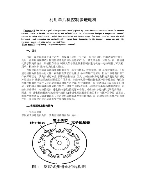
[Key Words]Singlechip ;Stepmotor;system;control一.引言目前 ,步进电机在工业生产及一些仪器上应用十分广泛 ,但步进电机的驱动信号往往还是用一些专用的模拟芯片控制器或者是信号发生器来产生 ,缺乏灵活性、可靠性。
在一些智能化要求较高的场合 ,用模拟芯片控制器及信号发生器来控制步进电机有一定的局限 ,可以采用单片机控制步进电机以改进其性能。
以步进电机为驱动装置构成的控制系统 ,具有价格低、控制简单、容易维护等优点。
且步进电机作为离散化执行元件 ,在数控及其它自动化设备中得到广泛应用。
但由于步进电机常工作在开环状态 ,其失步或过冲直接影响控制精度。
因此 ,如何控制步进电机使其避免失步或过冲是提高步进驱动系统控制精度的有效方法。
步进电机是一种能将电脉冲信号转换成角位移和线位移的执行元件 ,步进驱动器是由缓冲寄存器.环行分配器、控制逻辑及正反转控制门组成 ,能把输入的电脉冲转换成环行脉冲 ,以便控制步进电机 ,功率放大器提高其驱动能力。
单片机控制步进电机外文文献翻译

单片机控制步进电机外文文献翻译单片机控制步进电机外文原文Stepping motor application and controlstepper motor is an electrical pulse will be converted into angular displacement of the implementing agencies. Put it in simple language-speaking: When the stepper drive pulse signal to a receiver, it drives stepper motor rotation direction by setting a fixed point of view (and the step angle). You can control the number of pulses to control the amount of angular displacement, so as to achieve the purpose of accurate positioning; At the same time, you can by controlling the pulsefrequency to control the motor rotation speed and acceleration, so as to achieve the purpose of speed.Stepper motor directly from the AC-DC power supply, and must use special equipment - stepper motor drive. Stepper motor drive system performance, in addition to their own performance with the motor on the outside, but also to a large extent depend on the drive is good or bad.A typical stepper motor drive system is operated by the stepper motor controller, stepper motor drives and stepper motor body is composed of three parts. Stepper motor controller stepper pulse and direction signal, each made of a pulse, stepper motor-driven stepper motor drives a rotor rotating step angle, that is, step-by-step further. High or low speed stepper motor, or speed, or deceleration, start or stop pulses areentirely dependent on whether the level or frequency. Decide the direction of the signal controller stepper motor clockwise or counterclockwise rotation. Typically, the stepper motor drive circuit from the logic control, power driver circuit, protection circuit and power components. Stepper motor drive controller, once received from the direction of the signal and step pulse, the control circuit on a pre-determined way of the electrical power-phase stepper motor excitation windings of the conduction or cut-off signal. Control circuit output signal power is low, can not provide the necessary stepping motor output power, the need for power amplifier, which is stepper motor driven power drive part. Power stepper motor drive circuit to control the input current winding to form a space for rotating magnetic field excitation, the rotor-driven movement. Protection circuit in the event of short circuit, overload, overheating, such as failure to stop the rapid drive and motor.Motor is usually for the permanent magnet rotor, when the current flows through the stator windings, the stator windings produce a magnetic field vector. The magnetic field will lead to a rotor angle of rotation, making a pair of rotor and stator magnetic field direction of the magnetic field direction. When the stator rotating magnetic field vector from a different angle. Also as the rotor magnetic field to a point of view. An electrical pulse for each input, the motor rotation angle step. Its output and input of the angular displacement is proportional to the pulses, with pulse frequency proportional to speed.Power to change the order of winding, the electrical will be reversed. We can, therefore, control the pulse number, frequency and electrical power windings of each phase to control the order of rotation of stepper motor.Stepper motor types:Permanent magnet (PM). Magnetic generally two-phase stepper, torque and are smaller and generally stepping angle of 7.5 degrees or 15 degrees; put more wind for air-conditioning.Reactive (VR), the domestic general called BF, have a common three-phase reaction, step angle of 1.5 degrees; also have five-phase reaction. Noise, no torque has been set at a large number of out.Hybrid (HB), common two-phase hybrid, five-phase hybrid, three-phase hybrid, four-phase hybrid, two-phase can be common with the four-phase drive, five-phase three-phase must be used with their drives;Two-phase, four-phase hybrid step angle is 1.8 degrees more than a small size, great distance, and low noise;Five-phase hybrid stepping motor is generally 0.72, the motor step angle small, high resolution, but the complexity of drive circuits,wiring problems, such as the 5-phase system of 10 lines.Three-phase hybrid stepping motor step angle of 1.2 degrees, but according to the use of 1.8 degrees, the three-phase hybrid stepping motor has a two-phase mixed than the five-phase hybrid more pole will help electric folder symmetric angle, it can be more than two-phase,five-phase high accuracy, the error even smaller, run moresmoothly.Stepper motor to maintain torque: stepper motor power means no rotation, the stator locked rotor torque. It is a stepper motor, one of the most important parameters, usually in the low-speed stepper motor torque at the time of close to maintain the torque. As the stepper motor output torque increases with the speed of constant attenuation, the output power also increases with the speed of change, so as to maintain torque on the stepper motor to measure the parameters of one of the most important. For example, when people say that the stepper motor 2N.m, in the absence of special circumstances that means for maintaining the torque of the stepper motor 2N.m.Precision stepper motors: stepper motor step angle accuracy of 3-5%, not cumulative.Stepper motor to allow the minimum amount of surfacetemperature:Steppermotor causes the motor temperature is too high the first magnetic demagnetization, resulting in loss of torque down even further, so the motor surface temperature should be the maximum allowed depending on the motor demagnetization of magnetic material points; Generally speaking, the magnetic demagnetization points are above 130 degrees Celsius, and some even as high as 200 degrees Celsius, so the stepper motor surface temperature of 80-90 degrees Celsius is normal.Start frequency of no-load: the stepper motor in case of no-load to the normal start of the pulse frequency, if the pulse frequency ishigher than the value of motor does not start, possible to lose steps or blocking. In the case of the load, start frequency should be lower. If you want to achieve high-speed rotation motor, pulse frequency should be to accelerate the process, that is, the lower frequency to start, and then rose to a certain acceleration of the desired frequency (motor speed from low rise to high-speed).Step angle: that is to send a pulse, the electrical angle corresponding to rotation.Torque positioning: positioning torque stepper motor does not refer to the case of electricity, locked rotor torque stator.Operating frequency: step-by-step stepper motor can run without losing thehighest frequency.Subdivision Drive: stepper motor drives the main aim is to weaken or eliminate low-frequency vibration of the stepper motor to improve the accuracy of the motor running. Reduce noise. If the step angle is 1.8 ? (full step) the two-phase hybrid stepping motor, if the breakdown of the breakdown of the number of drives for the 8, then the operation of the electrical pulse for each resolution of 0.072 ?, the precision of motor can reach or close to 0.225 ?, also depends on the breakdown of the breakdown of the drive current control accuracy and other factors, the breakdown of the number of the more difficult the greater the precision of control.How to determine the stepper motor driver DC power supply:A. Determination of the voltage: Hybrid stepping motor driver power supplyvoltage is generally a wide range (such as the IM483 supply voltage of 12 ~ 48VDC), the supply voltage is usually based on the work of the motor speed and response to the request to choose. If the motor operating speed higher or faster response to the request, then the voltage value is high, but note that the ripple voltage can not exceed the maximum input voltage of the drive, or it may damage the drive.B. Determination of CurrentPower supply current is generally based on the output phase current drive I to determine. If a linear power supply, power supply current is generally preferable 1.1 to 1.3 times the I; if we adopt the switching power supply, power supply current is generally preferable to I, 1.5 to 2.0 times.The main characteristics of stepping motor:1. A stepper motor drive can be added operate pulse drive signal must be no pulse when the stepper motor at rest, such as If adding the appropriate pulse signal, it will to a certain angle (called the step angle) rotation. Rotation speed and pulse frequency is proportional to.2. permanent magnet step angle stepper motor version is 7.5 degrees, 360 degrees around, takes 48 pulses to complete.3. stepper motor has instant start and rapid cessation of superior characteristics. Change the order of the pulse4(you can easily change the direction of rotation.Therefore, the current printers, plotters, robotics, and so devices are the core of the stepper motor as the driving force.Stepper motors have the following benefits: (1)Low cost(2)Ruggedness (3)Simplicity in construction (4)High reliability (5)No maintenance (6)Wideacceptance(7)No tweaking to stabilize (8)No feedback components are neededThey work in just about any environment Inherently more failsafethan servo motors. There isvirtually no conceivable failure within the stepper drive module that could cause the motor to run away. Stepper motors are simple to drive and control in an open-loop configuration. They only require four leads. They provide excellent torque at low speeds, up to 5 times the continuous torque of a brush motor of the same frame size or double the torque of the equivalent brushless motor. This often eliminates the need for a gearbox. A stepper-driven-system is inherently stiff, with known limits to the dynamic position error.Stepper Motor Disadvantages:Stepper motors have the following disadvantages:1. Resonance effects and relatively long settling times .2.Rough performance at low speed unless a microstep drive is used .3.Liability to undetected position loss as a result of operating open-loop .4. They consume current regardless of load conditions and therefore tend to run hot5. Losses at speed are relatively high and can cause excessive heating, and they are frequently noisy (especially at high speeds).6.They can exhibit lag-lead oscillation, which is difficult to damp.There is a limit to their available size, and positioning accuracy relies on the mechanics (e.g., ballscrew accuracy).Many of these drawbacks can be overcome by the use of a closed-loop control scheme.外文资料翻译译文步进电机应用和控制步进电机是将电脉冲转换成角位移的执行机构。
步进电机及其驱动系统简介中英文翻译
步进电机及其驱动系统简介中英文翻译Step characteristics for machine for angular displacement forentering the electrical engineering is first kind will give or getan electric shocking the pulse signal conversion cowgirl or line potential moving battery carry outing a piece, having the fast stopping, accurate step entering and directly accepting the arithmetic figure measuring, because of but got the extensive application.Such as in the drafting machine, print the machine and optical instrument inside, and all adopt the inside of a place control system for entering theelectrical engineering to positioning to paint the pen print head or optical prinipal, especially indrstry process the type control, and move to spread to feel the to can immediately attain the precision fixed position because of its precision and need not potential, and control the technique along with the calculator of continuously deveolp, applied to would be more and more extensive.Control and can is divided into the simple control sum the complicacyto control to motor two kind.The simple control points to proceedsto start to motor, the system move, positive and negative revolution and sequential plicacy the control point to the motor's revolving speed, screw angle, turning moment, tension, electric current etc. physics quantisty progress control.Control technique that thedevelopment that motor get force is in latest development achievement thatmicro-electronics technique, electric power electronics, spread to feel the the technique, automatic control the technique, tiny machine the application technique to wait.Exactly the advance of these techniques make the motor control the technique at near two 10-year insides change for turn overing the ground of day is take placed.Among them the motor's control division have already been controled by emulation gradually let locate to regard single flake machine as principle of microprocessor control, formation the mix control system of the arithmetic figure and emulation and the application of the pure arithmetic figure control system, combine control the direction to total amount word to quickly deveolp.The motor's drive part of power for using the piece experienced a few renewals1to change the on behalf, current switch speed sooner, more simple wholetype power piece of control the MOSFET become the main current with IGBT.Stepper motors have the following benefits:• Low cost• Ruggedness• Simplicity in construction• High reliability• No maintenance• Wide acceptance• No tweaking to stabilize• No feedback components are needed• They work in just about any environment• Inherently more failsafe than servo motors.There is virtually no conceivable failure within the stepper drive module that could cause the motor to run away. Stepper motors are simple to drive and control in an open-loop configuration. They onlyrequire fourleads. They provide excellent torque at low speeds, up to 5 timesthecontinuous torque of a brush motor of the same frame size or double thetorque of the equivalent brushless motor. This often eliminates the needfor a gearbox. A stepper-driven-system is inherently stiff, with knownlimits to the dynamic position error.Stepper Motor DisadvantagesStepper motors have the following disadvantages:• Res onance effects and relatively long settlingtimes• Rough performance at low speed unless amicrostep drive is used• Liability to undetected position loss as a result ofoperating open-loop• They consume current regardless of loadconditions and therefore tend to run hot• Losses at speed are relatively high and can causeexcessive heating, and they are frequently noisy(especially at high speeds).2• They can exhibit lag-lead oscillation, which isdifficult to damp. There is a limit to their availablesize, and positioning accuracy relies on themechanics (e.g., ballscrew accuracy). Many ofthese drawbacks can be overcome by the use ofa closed-loop control scheme.Note: The Compumotor Zeta Series minimizes orreduces many of these different stepper motor disadvantages.There are three main stepper motor types:• Permanent Magnet (P.M.) Motors• Variable Reluctance (V.R.) Motors• Hybrid MotorsWhen the motor is driven in its full-step mode, energizing two windings or “phases” at a time (see Fig. 1.8), the torque available oneach step will be the same (subject to very small variations in the motorand drive characteristics). In the half-step mode, we arealternatelyenergizing two phases and then only one as shown in Fig. 1.9. Assumingthe drive delivers the same winding current in each case, this will causegreater torque to be produced when there are two windings energized. Inother words, alternate steps will be strong and weak. This does not represent a major deterrent to motor performance—the available torqueis obviously limited by the weaker step, but there will be a significantimprovement in low-speed smoothness over the full-step mode.Applications in hazardous environmentsor in a vacuum may not be able to use a brushed motor. Either a stepper or a brushless motor is called for, depending on the demands of the load.Bear in mind that heat dissipation may be a problem in a vacuum when theloads are excessive.continuous duty applications suit the servo motor, and in fact astep motor should be avoided in such applications because the high-speed lossescan cause excessive motor heating.are the natural domain of the stepper due to its high torque at low speeds, good torque-to-inertia ratio and lack of commutation problems.The brushes of the DC motor can limit its potential for frequent starts,3stops and direction changes.continuous duty applications are appropriate to the step motor. At low speeds it is very efficient in terms of torque output relativeto bothsize and input power. Microstepping can be used to improve smoothness inlowspeed applications such as a metering pump drive for veryaccurate flowcontrol.Stepper motor is a stepper motor for precise electrical and mechanicalactuators, which are widely used in industrial machinery, digital control,for the system reliability, interoperability, maintainability, andcost-optimal, according to the control system functional requirements andControl system through the microcontroller memory, I/O interface, interrupt, keyboard, LED display of the expansion of the annular distributor stepping motor, drive and protection circuit, man-machineinterface circuit, interrupt system and reset circuit, a single voltagedrive circuit, etc.designed to achieve a four-phase stepper motor rotating, and emergency stop functions. To achieve the steppingmotorsystem in NC Machine Tools, system design, two external interrupts,inorder to achieve within a certain period of time stepper motor repeatedReversible function, ie, the turret CNC automatic feed movement.With thecontinuous development of single chip microcomputer, microcontroller inhousehold electronic products widely applied, since the since the earlysixties, the stepper motor applications are greatly enhanced. People useit to drive the clock and other instruments with pointers, printers,plotters, disk CD-ROM drive, a variety of automatic control valves, various tools, as well as robots and other mechanical devices. In addition,as the acIn addition, as the actuator, stepper motor is one ofmechanical and electrical integration of the key products are widely usedin a variety of automatic control systems, microelectronics and computertechnology with the development of its requirements with the Japanese fearof growing in all the field of application of the national economy has. Stepper motor digital control system of electromechanicalactuators commonly used, due to its high precision, small size, flexibleto control, so the smart meter and position control has been widely usedin large-scale integrated circuits technology development, and SCM The4increasing popularity of design features, the lowest price of the steppermotor control driver provides advanced technology and adequate resources.步进电机是一种将电脉冲信号转换成相应的角位移或线位移的机电执行元件,具有快速启停、精确步进以及直接接受数字量的特点,因而得到了广泛的应用。
步进电机及单片机英文文献及翻译

外文文献:Knowledge of the stepper motorWhat is a stepper motor:Stepper motor is a kind of electrical pulses into angular displacement of the implementing agency. Popular little lesson: When the driver receives a step pulse signal, it will drive a stepper motor to set the direction of rotation at a fixed angle (and the step angle). You can control the number of pulses to control the angular displacement, so as to achieve accurate positioning purposes; the same time you can control the pulse frequency to control the motor rotation speed and acceleration, to achieve speed control purposes.What kinds of stepper motor sub-:In three stepper motors: permanent magnet (PM), reactive (VR) and hybrid (HB) permanent magnet stepper usually two-phase, torque, and smaller, step angle of degrees or the general 15 degrees; reaction step is generally three-phase, can achieve high torque output, step angle of degrees is generally, but the noise and vibration are large. 80 countries in Europe and America have been eliminated; hybrid stepper is a mix of permanent magnet and reactive advantages. It consists of two phases and the five-phase: two-phase step angle of degrees while the general five-phase step angle of degrees generally. The most widely used Stepper Motor. What is to keep the torque (HOLDING TORQUE)How much precision stepper motor? Whether the cumulative:The general accuracy of the stepper motor step angle of 3-5%, and not cumulative. Stepper motor to allow the minimum amount of surface temperatureStepper motor to allow the minimum amount of surface temperature:Stepper motor causes the motor temperature is too high the first magnetic demagnetization, resulting in loss of torque down even further, so the motor surface temperature should be the maximum allowed depending on the motor demagnetization of magnetic material points; Generally speaking, the magnetic demagnetization points are above 130 degrees Celsius, and some even as high as 200 degrees Celsius,so the stepper motor surface temperature of 80-90 degrees Celsius is normal. How to determine the stepper motor driver DC power supply:A. Determination of the voltageHybrid stepping motor driver power supply voltage is generally a wide range (such as the IM483 supply voltage of 12 ~ 48VDC), the supply voltage is usually based on the work of the motor speed and response to the request to choose. If the motor operating speed higher or faster response to the request, then the voltage value is high, but note that the ripple voltage can not exceed the maximum input voltage of the drive, or it may damage the drive.B. Determination of CurrentPower supply current is generally based on the output phase current drive I to determine. If a linear power supply, power supply current is generally preferable to times the I; if we adopt the switching power supply, power supply current is generally preferable to I, to times.The main characteristics of stepping motor:A stepper motor drive can be added operate pulse drive signal must be no pulse when the stepper motor at rest, such asIf adding the appropriate pulse signal, it will to a certain angle (called the step angle) rotation. Rotation speed and pulse frequency is proportional to.2 Dragon step angle stepper motor version is degrees, 360 degrees around, takes 48 pulses to complete.3 stepper motor has instant start and rapid cessation of superior characteristics.Change the pulse of the order of 4, you can easily change the direction of rotation. Therefore, the current printers, plotters, robotics, and so devices are the core of the stepper motor as the driving force.Stepper motor control exampleWe use four-phase unipolar stepper motor as an example. The structure shown in Figure 1:Four four-phase winding leads (as opposed to phase A1 A2 B1 phase phase B2) andtwo public lines (to the power of positive). The windings of one phase to the power of the ground. So that the windings will be inspired. We use four-phase eight-beat control, ie, 1 phase 2 phase alternating turn, would enhance resolution. ° per step can be transferred to control the motor excitation is transferred in order as follows:If the requirements of motor reversal, the transmission excitation signal can be reversed. 2 control schemeControl system block diagram is as followsThe program uses AT89S51 as the main control device. It is compatible with the AT89C51, but also increased the SPI interface and the watchdog module, which not only makes the debugging process becomes easy and also more stable. The microcontroller in the program mainly for field signal acquisition and operation of the stepper motor to calculate the direction and speed information. Then sent to the CPLD.CPLD with EPM7128SLC84-15, EPM7128 programmable logic device of large-scale, for the ALTERA company's MAX7000 family. High impedance, electrically erasable and other characteristics, can be used for the 2500 unit, the working voltage of +5 V. CPLD receives information sent from the microcontroller after converted to the corresponding control signal output to the stepper motor drive. Put the control signal drives the motor windings after the input, to achieve effective control of the motor. The hardware structure of the motor driveMotor drive using the following circuit:R1-R8 in which the resistance value of 320Ω. R9-R12 resistance value Ω. Q1-Q4 as Darlington D401A, Q5-Q8 for the S8550. J1, J2 and the stepper motor connected to the six-lead。
步进电机及单片机英文文献及翻译

步进电机及单片机英文文献及翻译————————————————————————————————作者:————————————————————————————————日期:2外文文献:Knowledge of the stepper motorWhat is a stepper motor:Stepper motor is a kind of electrical pulses into angular displacement of the implementing agency. Popular little lesson: When the driver receives a step pulse signal, it will drive a stepper motor to set the direction of rotation at a fixed angle (and the step angle). You can control the number of pulses to control the angular displacement, so as to achieve accurate positioning purposes; the same time you can control the pulse frequency to control the motor rotation speed and acceleration, to achieve speed control purposes.What kinds of stepper motor sub-:In three stepper motors: permanent magnet (PM), reactive (VR) and hybrid (HB) permanent magnet stepper usually two-phase, torque, and smaller, step angle of 7.5 degrees or the general 15 degrees; reaction step is generally three-phase, can achieve high torque output, step angle of 1.5 degrees is generally, but the noise and vibration are large. 80 countries in Europe and America have been eliminated; hybrid stepper is a mix of permanent magnet and reactive advantages. It consists of two phases and the five-phase: two-phase step angle of 1.8 degrees while the general five-phase step angle of 0.72 degrees generally. The most widely used Stepper Motor.What is to keep the torque (HOLDING TORQUE)How much precision stepper motor? Whether the cumulative:The general accuracy of the stepper motor step angle of 3-5%, and not cumulative.- 0 -Stepper motor to allow the minimum amount of surface temperatureStepper motor to allow the minimum amount of surface temperature:Stepper motor causes the motor temperature is too high the first magnetic demagnetization, resulting in loss of torque down even further, so the motor surface temperature should be the maximum allowed depending on the motor demagnetization of magnetic material points; Generally speaking, the magnetic demagnetization points are above 130 degrees Celsius, and some even as high as 200 degrees Celsius, so the stepper motor surface temperature of 80-90 degrees Celsius is normal.How to determine the stepper motor driver DC power supply:A. Determination of the voltageHybrid stepping motor driver power supply voltage is generally a wide range (such as the IM483 supply voltage of 12 ~ 48VDC), the supply voltage is usually based on the work of the motor speed and response to the request to choose. If the motor operating speed higher or faster response to the request, then the voltage value is high, but note that the ripple voltage can not exceed the maximum input voltage of the drive, or it may damage the drive.B. Determination of CurrentPower supply current is generally based on the output phase current drive I to determine. If a linear power supply, power supply current is generally preferable 1.1 to 1.3 times the I; if we adopt the switching power supply, power supply current is generally preferable to I, 1.5 to 2.0 times.The main characteristics of stepping motor:A stepper motor drive can be added operate pulse drive signal must be no- 1 -pulse when the stepper motor at rest, such asIf adding the appropriate pulse signal, it will to a certain angle (called the step angle) rotation. Rotation speed and pulse frequency is proportional to.2 Dragon step angle stepper motor version is 7.5 degrees, 360 degrees around, takes 48 pulses to complete.3 stepper motor has instant start and rapid cessation of superior characteristics.Change the pulse of the order of 4, you can easily change the direction of rotation.Therefore, the current printers, plotters, robotics, and so devices are the core of the stepper motor as the driving force.Stepper motor control exampleWe use four-phase unipolar stepper motor as an example. The structure shown in Figure 1:Four four-phase winding leads (as opposed to phase A1 A2 B1 phase phase B2) and two public lines (to the power of positive). The windings of one phase to the power of the ground. So that the windings will be inspired. We use four-phase eight-beat control, ie, 1 phase 2 phase alternating turn, would enhance resolution. 0.9 °per step can be transferred to control the motor excitation is transferred in order as follows:If the requirements of motor reversal, the transmission excitation signal can be reversed. 2 control schemeControl system block diagram is as followsThe program uses AT89S51 as the main control device. It is compatible with- 2 -the AT89C51, but also increased the SPI interface and the watchdog module, which not only makes the debugging process becomes easy and also more stable. The microcontroller in the program mainly for field signal acquisition and operation of the stepper motor to calculate the direction and speed information. Then sent to the CPLD.CPLD with EPM7128SLC84-15, EPM7128 programmable logic device of large-scale, for the ALTERA company's MAX7000 family. High impedance, electrically erasable and other characteristics, can be used for the 2500 unit, the working voltage of +5 V. CPLD receives information sent from the microcontroller after converted to the corresponding control signal output to the stepper motor drive. Put the control signal drives the motor windings after the input, to achieve effective control of the motor. 2.1 The hardware structure of the motor driveMotor drive using the following circuit:R1-R8 in which the resistance value of 320Ω. R9-R12 resistance value 2.2KΩ. Q1-Q4 as Darlington D401A, Q5-Q8 for the S8550. J1, J2 and the stepper motor connected to the six-lead。
基于单片机的步进电机控制系统设计外文资料翻译
毕业设计(论文)外文资料翻译学院:机械工程学院专业:机械设计制造及其自动化姓名:张XX学号:XXXXXXXXXX外文出处:《Computational Intelligence and (用外文写)Design》附件: 1.外文资料翻译译文;2.外文原文。
注:请将该封面与附件装订成册。
附件1:外文资料翻译译文基于微型计算机的步进电机控制系统设计孟天星余兰兰山东理工大学电子与电气工程学院山东省淄博市摘要本文详细地介绍了一种以AT89C51为核心的步进电机控制系统。
该系统设计包括硬件设计、软件设计和电路设计。
电路设计模块包括键盘输入模块、LED显示模块、发光二极管状态显示和报警模块。
按键可以输入设定步进电机的启停、转速、转向,改变转速、转向等的状态参数。
通过键盘输入的状态参数来控制步进电机的步进位置和步进速度进而驱动负载执行预订的工作。
运用显示电路来显示步进电机的输入数据和运行状态。
AT89C51单片机通过指令系统和编译程序来执行软件部分。
通过反馈检测模块,该系统可以很好地完成上述功能。
关键词:步进电机,AT89C51单片机,驱动器,速度控制1概述步进电机因为具有较高的精度而被广泛地应用于运动控制系统,例如机器人、打印机、软盘驱动机、绘图仪、机械式阀体等等。
过去传统的步进电机控制电路和驱动电路设计方法通常都极为复杂,由成本很高而且实用性很差的电器元件组成。
结合微型计算机技术和软件编程技术的设计方法成功地避免了设计大量复杂的电路,降低了使用元件的成本,使步进电机的应用更广泛更灵活。
本文步进电机控制系统是基于AT89C51单片机进行设计的,它具有电路简单、结构紧凑的特点,能进行加减速,转向和角度控制。
它仅仅需要修改控制程序就可以对各种不同型号的步进电机进行控制而不需要改变硬件电路,所以它具有很广泛的应用领域。
2设计方案该系统以AT89C51单片机为核心来控制步进电机。
电路设计包括键盘输入电路、LED显示电路、发光二极管显示电路和报警电路,系统原理框图如图1所示。
单片机外文翻译----基于MSP430F149单片机实现的步进电机通用控制器

中文1597字Step of electric machine universal controller realizes whichbased on the MSP430F149 Single Chip Microcomputer.Abstract:With the infiltration in the social field of the computer in recent years, the application of the one-chip computer is moving towards deepening constantly, drive tradition is itmeasure crescent benefit to upgrade day to control at the same time. In measuring in real time andautomatically controlled one-chip computer application system, the one-chip computer often usesas a key part, only one-chip computer respect knowledge is not enough, should also follow thestructure of the concrete hardware , and direct against and use the software of target'scharacteristic to combine concretely, in order to do perfectly.This article mainly introduced realizes a step of machine universal controller based on the MSP430F149 monolithic integrated circuit. This controller may simultaneously control the multi-tablecloths machine according to the curve way movement, including adds and subtracts fast, the localization and the commutation function and so on. In the article discussed with emphasis step machine has risen to low the speed and the curve design proposal and its the realization method.1. a preface:based on the step of machine control system, except step machine generally also needs the special actuation power source, actuates the power source merely to complete the power actuation part, the user certainly cannot cause the entire control system according to prearrange, the expectation active status movement, must control to its actuation power source, the user needs to develop once more.In view of this, has designed a step of machine universal controller which realizes based onthe MSP430F149 monolithic integrated circuit, may satisfy the majority controllingfield originally request. The controller main function is:(1) May control the multi- wraps step of machine actuation system; At present may simultaneously control 3 sets of systems.(2) work way is flexible, may according to the hypothesis curve movement, the curve most reach 8 sections; May according to the control signal movement which exterior examines; May according to the simulation adjustment test function movement;2. Systems designs2.1 systems structureThis controller has mainly realized thematic- tablecloths machine in the multistage curve operating control.2.2 microprocessors choiceThis design has selected MSP which Incorporation produces series monolithic integrated circuit MSP430F149.The goal is applies its rich connection resources and the formidable timer function, the MSP430F149 performance characteristic as follows:(1) 6 eight bit parallel connections; Definitely may realize this system all signals input, the output, does not need the hardware to expand, P1, the P2 eight bit parallel ports each mouth line all has the severance function, softly causes the keyboard, the hardware design to change is extremely simple.(2) 12 A/D switch ADC; Completes the simulation hypothesis function.(3) Formidable timer function; TIMER-A3, TIMER-B7 respectively be have3 and 7 captures/compares the register 16 timers, may satisfy the system speed the hypothesis and the curve fixed time request.(4)Liquid crystal actuation module;(5) In sets at 2KB RAM, 60KB FLASH;MSP430F149 provides the rich resources, the periphery hardware expands only must do the very few work, not only designs changes extremely imply, and moreover this controller volume small, the reliability is high.2.3 steps of machine starting and add/decelerate the control planThe step of motive highest starting frequency (step frequency) generally is 0.1KHz arrives 3-4KHz, but the highest movement frequency may achieve N*102 KHz. Surpasses the highest starting frequency the frequency direct-on starting, will appear\" Falls out of step \" Phenomenon, even is unable to start.The more ideal starting curve should be according to the index rule starting. But the practical application to starts the section processing to be possible to use according to the fitting a straight Line method, namely \" Steps and ladders law \”. May according to two kind of situations processing, (1) known frequency press the frequency partition to start, the partition counts n=f/f q.(2) Unknown frequency, then to assigns according to the section. Uses \" Steps and ladders law \" Continuously raises the speed the speed which needs, then locking, according to pre-placed curve movement. Fitting the starting frequency, after each section of frequencies hand over the increase (to call steps and ladders frequency) △f=f/8, namely uses 8 sections of fitting. In the operating control process, (frequency) divides into the outset speed n minute achievement steps and ladders frequency, When 2.4 steps of machine commutation questions step of machine commutation, certainly must stop in the electrical machinery or fall commutates again to the frequency range in, in order to avoid has a bigger impact to damage the electrical machinery. The commutation signal certainly must last the CP pulse finish after the preceding direction as well as in front of the next direction first CP pulse sends out.2.4 steps of machine commutation questionsStep of machine commutation, certainly must stop in the electrical machinery or fall commutates again to the frequency range in, in order to avoid has a bigger impact to damage theelectrical machinery. The commutation signal certainly must last the CP pulse finish after the preceding direction as well as in front of the next direction first CP pulse sent out in some high speed under, the reverse cut essence has contained -> the commutation -> three processes2.5 speeds and the timer starting value transformationThis system speed control is the dependence fixed time produces; the hypothesis speed which the CP pulse completes with has the CP pulse timer starting value to have the certain relations. The MSP430F149 timer work way has many kinds of, this design timer work under continual way. In the continual pattern, the timer starts from its current value to count, after counts to 0FFFFH from \" 0\" Starts redo count. Under this way, compares the timer current value and comparison register CCRX, if equal has the severance, and May the time which has the next event add to in this interrupt service is on comparison register CCRX.Fixed time the starting value = must fixed time the value/count the cycle; Often assigns regarding the step of machine its speed value by the frequency form, such as movement under 20KHZ, therefore the previous type may transform is: Fixed time the starting value = counts the frequency/speed value. (Counts frequency for system clock frequency)3. ConcludingRemark this controller may realize step machine under the multistage hypothesis curve operating control, has the hardware simply, the reliable high characteristic, has used in on the electric wire production line platoon line control section it, has obtained the satisfying effect. This topic funds the project for the north industry big school scientific research foundation.译文译文基于MSP430F149单片机实现的步进电机通用控制器摘要:近年来随着计算机在社会领域的渗透, 单片机的应用正在不断地走向深入,同时带动传统控制检测日新月益更新。
步进电机运动控制系统外文文献翻译中英文

外文文献翻译(含:英文原文及中文译文)文献出处:YH Lee. Stepper motor motion control system design [J]. Equipment Manufacturing Technology, 2015,2(6):31-41.英文原文Stepper motor motion control system designYH LeeAbstractStepper motors are open-loop control elements that convert electrical pulse signals to angular or linear displacements. In the case of non-overload, the rotation speed and stop position of the motor depend only on the frequency and pulse number of the pulse signal, and is not affected by the load change, that is, a pulse signal is applied to the motor, and the motor rotates through a step angle. The existence of this linear relationship, coupled with the fact that the stepper motor has only periodic errors and no cumulative errors, is a feature. It is very simple to use a stepper motor to control the speed and position. Stepper motor speed control is generally to change the frequency of the input stepper motor pulse to achieve stepper motor speed control, because the stepper motor for each pulse to rotate a fixed angle, so that you can control the stepper motor The time interval from one pulse to the next pulse changes the frequency of the pulse. The length of the delay controls the step anglespecifically to change the rotation speed of the motor, thereby realizing the stepping motor speed control. In this design scheme, the internal timer of the A T89C51 microcontroller is used to change the frequency of the CP pulse to realize the control of the rotation speed of the stepper motor to realize the functions of the motor speed adjustment and forward and reverse rotation. The design takes into consideration that the CPU may be disturbed when executing instructions, causing the program to "run away" or enter the "endless loop". Therefore, the watchdog circuit is designed using a microprocessing system monitoring integrated chip manufactured by MAXIM. MAXI813. This article also gives the related hardware block diagram and software flow chart in detail, and has compiled the assembly language program.Keywords: stepper motor single chip microcomputer speed control systemIntroductionStepper motors were first developed by the British in 1920. The invention of the transistor in the late 1950s was also gradually applied to a stepping motor, which made it easier to control the digitization. After continuous improvement, today's stepper motors have been widely used in mechanical systems with high controllability such as high positioning accuracy, high decomposition performance, high responsiveness, and reliability. In the production process, where automation, labor saving, andhigh efficiency are required, we can easily find traces of stepper motors, especially those that emphasize speed, position control, and flexible control applications that require precise command operation. The most. As an actuator, a stepper motor is one of the key products of electromechanical integration and is widely used in various automation control systems. With the development of microelectronics and computer technology, the demand for stepper motors is increasing day by day, and there are applications in various national economic fields. A stepper motor is an actuator that converts an electrical pulse signal into an angular or linear displacement. Stepper motors can be driven directly with digital signals and are very easy to use. The general motor is continuous rotation, while the stepper motor has two basic states of positioning and operation. When there is a pulse input, the stepping motor rotates step by step, and when it is given a pulse signal, it turns a certain angle. The angular displacement of the stepping motor is strictly proportional to the number of input pulses and is synchronized in time with the input pulse. Therefore, as long as the number of input pulses, the frequency, and the phase sequence of the motor windings are controlled, the desired rotation angle can be obtained. Speed and direction of rotation. When there is no pulse input, the air gap magnetic field can keep the rotor in the original position under the excitation of the winding power supply. So it is very suitable for single chip microcomputer control. Stepper motors also havefeatures such as fast start, precise stepping and positioning, and are thus widely used in CNC machine tools, plotters, printers, and optical instruments. Stepping motors have become the third category of motors except for DC motors and AC motors. Traditional electric motors, as electromechanical energy conversion devices, play a key role in human production and life into the electrification process. The stepper motor can be used as a special motor for control, and it is widely used in various open-loop control because it has no accumulated error (accuracy is 100%). Now more commonly used stepper motors include reactive stepper motors (VR), permanent magnet stepper motors (PM), hybrid stepper motors (HB), and single-phase stepper motors. Permanent-magnet type stepping motor is generally two-phase, small torque and volume, step angle is generally 7.5 degrees or 15 degrees; Reactive stepping motor is generally three-phase, can achieve large torque output, stepping The angle is generally 1.5 degrees, but the noise and vibration are large. The rotor of the reactive stepper motor is magnetically routed from a soft magnetic material, and the stator has a multi-phase excitation winding, which generates torque using a change in the magnetic permeability. Hybrid stepping motor refers to the advantage of mixing permanent magnet type and reactive type. It is divided into two phases and five phases: the two-phase step angle is generally 1.8 degrees and the five-phase step angle is generally 0.72 degrees. This type of steppermotor is the most widely used and is also the stepper motor used in this subdivision drive scheme.1 stepper motor overview1. 1 stepper motor features:1) The accuracy of a typical stepper motor is 3-5% of the step angle and does not accumulate. 2) The allowable temperature of the stepper motor is high. Excessively high temperature of the stepping motor first demagnetizes the magnetic material of the motor, resulting in a drop in torque and even loss of synchronism. Therefore, the maximum temperature allowed for the appearance of the motor should depend on the demagnetization point of the magnetic material of different motors; generally, the demagnetization of the magnetic material. The points are all above 130 degrees Celsius, and some are even up to 200 degrees Celsius. Therefore, the external temperature of the stepper motor is completely normal at 80-90 degrees Celsius. 3) The torque of the stepper motor will decrease as the rotation speed increases. When the stepper motor rotates, the inductance of each phase winding of the motor will form a counter electromotive force; the higher the frequency, the greater the counter electromotive force. Under its effect, the motor's phase current decreases as the frequency (or speed) increases, causing the torque to drop. 4) The stepping motor can run normally at low speed, but it cannot start if it is higher than a certain speed, accompanied by howling. The stepper motorhas a technical parameter: No-load starting frequency, that is the pulse frequency that the stepping motor can start normally under no-load conditions. If the pulse frequency is higher than this value, the motor cannot start normally, and step loss or stall may occur. In the case of load, the starting frequency should be lower. If the motor is to be rotated at a high speed, the pulse frequency should have an acceleration process, that is, the starting frequency is low, and then it is increased to a desired high frequency (motor speed is raised from low speed to high speed) at a certain acceleration. TC \* MERGEFORMA T1. 2 working principle of stepping motorA stepper motor is a type of motor that is controlled by an electrical pulse and converts the electrical pulse signal into a phase-shifted motor whose mechanical displacement and rotational speed are proportional to the number of pulses and the pulse frequency of the input motor winding. Each pulse signal can be stepped The feed motor rotates at a fixed angle. The number of pulses determines the total angle of rotation. The frequency of the pulse determines the speed of the motor. When the stepper receives a pulse signal, it drives the stepper motor to rotate in the set direction. At a fixed angle (called "step angle"), its rotation is performed step by step at a fixed angle. By controlling the number of pulses to control the angular displacement, so as to achieve the purpose of accurate positioning; At the same time, by controlling the pulse frequencyto control the speed and acceleration of the motor rotation, so as to achieve the purpose of speed control.2 Basic requirements for designStudy the characteristics, working principle, and specific speed regulation principle of stepper motor. TC \* MERGEFORMA T Basic requirements The stepper motor uses a three-phase stepper motor with a power of 1W. When the speed is in the range of 0 to 1000r/min, the maximum accuracy is 2%. To basically complete the graduation design, the stepper motor can perform precise speed control, positive and negative rotation, and it can not lose step when starting. Basically, there is no Oscillation, can complete the complete hardware circuit diagram, software design.3 Argumentation of the plan3.1 Determination of control methodsAlthough the stepper motor control is a relatively accurate, open-loop stepper motor control system has the advantages of low cost, simple, convenient control, etc., in the open-loop system of the stepper motor using the microcontroller, the frequency of the CP pulse of the control system or change The cycle is actually controlling the speed of the stepper motor. There are two ways the system can achieve stepper motor speed control. One is delay, the other is timing. The delay method is to call a delay subroutine after each commutation. After the delay isover, the commutation is executed again. In this way, CP pulses or commutation cycles with a certain frequency can be issued. The delay time of the delay subroutine and the time used by the commutation program are the cycles of the CP pulse. This method is simple, uses less resources, and is implemented by software. Different subroutines can be called to achieve different speeds. However, it takes a long time to process the CPU and cannot handle other tasks at runtime. Therefore, it is only suitable for a simpler control process. The timing method is to use the timer timing function in the microcontroller system to generate an arbitrary period of the timing signal, so that the period of the system output CP pulse can be conveniently controlled. When the timer is started, the timer counts up the system and its cycle starting from the loaded initial value. When the timer overflows, the timer generates an interrupt and the system transfers to execute the timer interrupt subroutine. The motor commutation subroutine is placed in the timer interrupt service routine. The timer interrupt is once and the motor is reversed once to achieve motor speed control. Since there is a certain time interval from the start of restarting the timer to the timer application interruption, the timing time is increased. In order to reduce this timing error and achieve accurate timing, it is necessary to make appropriate adjustments to the initial value of reloading counts. . The initial value of adjusted reloading mainly considers two factors and one is the time required to interrupt theresponse. The second is the time occupied by reloading the initial value instruction, including other instructions that interrupt the service program before reloading the initial value. After these two factors are combined, the correction amount of the reload count initial value takes 8 machine cycles, that is, the timing time is shortened by 8 machine cycles. When using the timer interrupt to control the motor shift, it is actually changing the size of the timer load value. In the control process, a discrete approach is used to approximate the ideal speed curve. In order to reduce the time for calculating the load value in each step, the load value required for the speed of each discrete point is fixed in the ROM of the system when the system is designed. The system uses the table look-up method to find the required load value in the system. Significantly reduce the time spent on CPU and improve the response speed of the system. Most stepper motor motion control systems are designed to run in an open-loop state, because the cost is low, and the position control inherent in the motion control technology can be provided without feedback. However, in some applications, more reliability, security, or product quality assurance is required. Therefore, closed-loop control is also an option. Here are some methods for achieving closed-loop control of stepper motors: 1) Step-by-step confirmation, This is the simplest displacement control, using a low-value optical encoder to calculate the amount of step movement. A simple loop compares the stepper motor with the commandverification and verifies that the stepper motor moves to the expected position; 2) Back-EMF, a sensorless detection method, uses a stepper motor's back EMF (eleCtromotiveCe, emf) signal , Measure and control speed. When the back-EMF voltage drops to the monitoring detection level, the closed-loop control is changed to the standard open-loop to complete the final displacement movement; 3) Full-servo control refers to the full-time use of feedback devices for stepper motors - encoders, decoding , or other feedback sensors to more accurately control the stepper motor displacement and torque. Other methods include a variety of different back-EMF control motor parameter measurements and software techniques that some manufacturers use. Here, the stepper drive monitors and measures the motor coils and uses voltage current information to increase the stepper motor control. Positive damping uses this information to block the speed of vibration, producing more usable torque output and reducing torque-induced mechanical vibration losses. No encoder installation monitoring uses information to detect the loss of synchronous speed. Conventional stepper motor control usually employs feedback devices and non-sensing methods, and is an effective method to implement a sports application with safety requirements, dangerous conditions or high accuracy requirements. Most stepper motor-based systems typically operate in an open-loop state, which provides a low-cost solution. In fact, stepper systems can improve the performanceof displacement control without feedback. However, when the stepper motor is running in open loop, there may be a simultaneous loss between the command pace and the actual step. Closed-loop control, which is part of traditional step control, can effectively provide higher reliability, safety, or product quality. In these stepper systems, the closed loop of the feedback device or indirect parametric sensing method can correct or control out-of-step, monitor motor stagnation, and ensure greater available torque output. Recently, closed-loop control (CLC) of stepper motors can also help implement smart distributed motion architectures. However, there is a risk of out-of-step operation in open-loop operation, which will result in positioning errors. However, compared to encoders used in servo systems, closed-loop stepper motors use encoders that are less costly. Therefore, closed-loop control is selected.3.2 Determination of Drive ModeThere are generally two methods for driving a stepping motor. One is directly driven by the CPU. This method is generally not suitable because the output current pulse of the CPU is extremely small and it cannot sufficiently rotate the stepping motor. One is indirect driving by the CPU, which is to amplify the signal output from the CPU, and then directly drive or indirectly drive the stepper motor through photoelectric isolation. This method is relatively safe and reliable. The solid design should use a CPU to drive the stepper motor indirectly. Thetachogenerator of the encoder is also used as the speed measurement tool. Because the closed-loop control is selected, there must be feedback components. There are generally two types of feedback components. One is the coaxial tachometer generator, and the speed of the stepping motor is fed back. Back, and then through the display and stepper motor adjustment; Another is through the optical coaxial encoder to the stepper motor speed feedback back to the stepper motor to adjust; compared to the latter, the latter The design is relatively simple, inexpensive, safe and reliable, and less polluting. The latter is generally used for solids, and photoelectric crumblers are used as feedback components.3. 3 Selection of Drive CircuitThere are many kinds of driving motors for stepping motors, but the most common ones are single voltage driving, dual voltage driving, chopper driving, subdivision control driving and so on. Single-voltage driving is the simplest driving circuit in stepper motor control. It is essentially a single-phase inverter. Its greatest feature is its simple structure, because of its low work efficiency, especially its prominent features at high frequencies. Its external resistor R consumes a considerable amount of heat, which affects the stability of the circuit. This type of drive is generally used only in the drive circuit of a low-power stepper motor. Dual-voltage driving is generally driven by two power supply voltages. Since these two power supplies are one highvoltage and one low voltage, they are also called high and low voltage driving circuits. The disadvantage of the dual-voltage driving circuit is that the valley point appears in the current at the high-low voltage connection, which inevitably causes the torque to drop at the valley point. Not suitable for normal operation of the motor. For the chopper circuit drive, this disadvantage can be overcome and the efficiency of the stepper motor can also be improved. Therefore, it is a good driver circuit from the standpoint of improving efficiency. It can use a higher power supply voltage and does not require an external resistor to limit the rated current and reduce the time constant. However, due to the sawtooth fluctuations at the top of the waveform, large electromagnetic noise is generated. The subdivision drive is powered by a pulse voltage. For a voltage pulse, the rotor can rotate one step. Generally, according to the voltage pulse distribution method, each phase winding of the stepping motor will alternately switch, and the rotor of the stepping motor can be fixed. Rotate. The subdivided control circuit is generally divided into two types. One is to use a linear analog power amplifier to obtain a staircase current. This method is simple but inefficient. The other method is to use a single-chip microcomputer to obtain the step current by using the method of pulse width modulation. This method requires complex calculations to make the substepped step angles uniform. However, due to the fact that the design of the stepper motor requires a relatively wide range ofhigh-speed adjustments, the drive chip 8713 should be used to drive the motor and the speed of the stepper motor must be controlled by software.中文译文步进电机运动控制系统设计作者:YH Lee摘要步进电机是将电脉冲信号转变为角位移或线位移的开环控制元件。
基于单片机的步进电机控制系统
基于单片机的步进电机控制系统作者:杨云等来源:《价值工程》2013年第05期摘要:传统步进电机控制系统往往采用硬件电路构成的控制器,电路复杂不易实现。
本文研究了基于单片机的步进电机控制方法,电路简单,实现了软件对电机进行各种操作,既降低了硬件成本又提高了控制的灵活性。
Abstract: The traditional stepper motor control system is often used controller with hardware circuit which is not easy to achieve due to complex circuit. This paper studied stepper motor control method based on SCM whose circuit is simple. It achieves various operations to motor of software,reduces hardware cost and increases the flexibility of the control.关键词:单片机;步进电机Key words: SCM;stepper motor中图分类号:TP31 文献标识码:A 文章编号:1006-4311(2013)05-0185-020 引言随着微电子技术和计算机技术的发展,步进电机广泛应用于电动玩具、打印机等消费类产品以及数控车床、医疗器械等机电类产品中,研究步进电机的控制系统,对提高控制的精度和响应速度以及节约成本方面都具有重要意义。
1 步进电机控制系统整体设计步进电机控制系统能够实现对步进电机转速、旋转时间(0s-9999s)的任意设定,并且支持正反转两种旋转方式。
同时具有简单的人机交互界面,是人们更加容易操作。
本系统由硬件系统和软件系统两部分组成。
硬件设计由单片机最小系统、电源模块、键盘控制模块、显示模块组成;软件设计包括键盘控制、步进电机脉冲、显示模块、以及转速计算模块的控制程序,最终实现对步进电机转动方向、转动时间的控制,并将步进电机的的转动速度、转动剩余时间显示在显示模块上面,如图1所示。
- 1、下载文档前请自行甄别文档内容的完整性,平台不提供额外的编辑、内容补充、找答案等附加服务。
- 2、"仅部分预览"的文档,不可在线预览部分如存在完整性等问题,可反馈申请退款(可完整预览的文档不适用该条件!)。
- 3、如文档侵犯您的权益,请联系客服反馈,我们会尽快为您处理(人工客服工作时间:9:00-18:30)。
毕业设计(论文)外文资料翻译
学院:机械工程学院
专业:机械设计制造及其自动化
姓名:
学号:XXXXXXXXXX
外文出处:《Computational Intelligence and (用外文写)Design》
附件: 1.外文资料翻译译文;2.外文原文。
注:请将该封面与附件装订成册。
附件1:外文资料翻译译文
基于微型计算机的步进电机控制系统设计
孟天星余兰兰
山东理工大学电子与电气工程学院
山东省淄博市
摘要
本文详细地介绍了一种以AT89C51为核心的步进电机控制系统。
该系统设计包括硬件设计、软件设计和电路设计。
电路设计模块包括键盘输入模块、LED显示模块、发光二极管状态显示和报警模块。
按键可以输入设定步进电机的启停、转速、转向,改变转速、转向等的状态参数。
通过键盘输入的状态参数来控制步进电机的步进位置和步进速度进而驱动负载执行预订的工作。
运用显示电路来显示步进电机的输入数据和运行状态。
AT89C51单片机通过指令系统和编译程序来执行软件部分。
通过反馈检测模块,该系统可以很好地完成上述功能。
关键词:步进电机,AT89C51单片机,驱动器,速度控制
1概述
步进电机因为具有较高的精度而被广泛地应用于运动控制系统,例如机器人、打印机、软盘驱动机、绘图仪、机械式阀体等等。
过去传统的步进电机控制电路和驱动电路设计方法通常都极为复杂,由成本很高而且实用性很差的电器元件组成。
结合微型计算机技术和软件编程技术的设计方法成功地避免了设计大量复杂的电路,降低了使用元件的成本,使步进电机的应用更广泛更灵活。
本文步进电机控制系统是基于AT89C51单片机进行设计的,它具有电路简单、结构紧凑的特点,能进行加减速,转向和角度控制。
它仅仅需要修改控制程序就可以对各种不同型号的步进电机进行控制而不需要改变硬件电路,所以它具有很广泛的应用领域。
2设计方案
该系统以AT89C51单片机为核心来控制步进电机。
电路设计包括键盘输入电路、LED显示电路、发光二极管显示电路和报警电路,系统原理框图如图1所示。
At89c51单片机的P2口输出控制步进电机速度的时钟脉冲信号和控制步进电机运转方向的高低电平。
通过定时程序和延时程序可以控制步进电机的速度和在某一
转向的运行时间。
运用驱动电路可以将微弱的脉冲信号放大成能使步进电机工作的强电信号,但是放大后的电流不能超过最大负荷能力。
使用PPM8713芯片可以增强驱动能力。
同时也可以连接一个专用的驱动芯片FT5754来放大工作电流,最大电流为3A,因此设计时应不超过该极限负载能力。
图1.系统原理方框图
当系统上电以后,我们首先将系统初始化,然后扫描整个键盘,如果某参数按键被按下了,通过输入参数可以设置运转的步数。
当参数输入完成以后按下确认键,就代表了参数设置成功。
我们还可以通过键盘上的按键来设置步进电机的正转与反转。
当所有设置完成以后,按下开始按钮步进电机就可以根据设置好的参数开始运行。
在运行期间,通过键盘上指定的按键可以对步进电机进行加速或减速,步进电机在正常转动的任意时刻,我们按下停止键,步进电机都将停止运行并且保持。
系统的显示模块采用专用驱动芯片PS7219,它能驱动八位数码管。
显示模块能显示步进电机的状态参数。
当步进电机处于静止状态,显显示模块可以显示输入参数,在正常运行阶段数码管的高八位和低八位可以分别显示步进电机的步数和回转圈数。
3 硬件电路设计
该系统选用型号为57BYG229的步进电机。
步进电机控制系统的硬件电路设计如图2所示。
硬件电路设计包括复位电路设计,定时电路设计,报警电路设计,键盘接口电路设计,驱动电路设计和LED显示电路设计。
图2硬件电路设计图
1.复位电路
复位操作包括两种方法:上电自动复位和按键手动复位。
上电自动复位由外部复位电路电路的电容充电完成。
该复位电路如图2所示。
系统上电时,RST口电平与VCC口电平相同,随着RC电路的充电电流的减弱,最终RST口电平变为低电平。
因此只要电源VCC口电流上升时间不超过1ms,就能实现上电自动复位,这就意味着系统可以凭借接通电源开关完成复位和初始化。
按键手动复位电路具有与上电复位电路同样的功能,当人为按下按钮时,则Vcc的+5V电平就会直接加到RST 端。
由于人的动作再快也会使按钮保持接通达数十毫秒,所以,完全能够满足复位的时间要求。
按键手动复位电路如图3所示。
2.定时电路
用软件编程的方法设置单片机内部定时器延时程序来改变脉冲频率从而实现步进电机的转速控制。
AT89C51单片机有两个内部定时器:T0和T1.定时器0在工作方式1情况下可以用软件编程法进行控制。
3.报警电路
蜂鸣器通常用来提示系统运行状态,例如当输入参数错误或则停止信号
已发出,蜂鸣器将结合状态指示灯提示当前工作状态。
蜂鸣器接口电路如图3所示。
蜂鸣器驱动电流较低,可以用三极管进行功率放大驱动。
在刚才的那种情况下,蜂鸣器会发出报警声并同时输出信号使P3.1口置0。
图3.基于PPM8713的步进电机驱动电路
P3.1口得输出脉冲被三极管放大来驱动蜂鸣器发出响应该警报的声音信号。
声音信号结束后,三极管停止工作,这是P3.1口输出电平置1。
4.键盘接口电路
通过键盘可以设置步进电机的启停、转速、转向等相关参数。
在开始启动步进电机的时候需要现在键盘上设置步进电机的平均转速和总的运行步数,所以键盘的功能是用来传送输入参数到单片机。
为了达到启动、停止系统并且控制步进电机的转向等目的,我们需要定义相应的按键来实现这些功能。
如图2所示,在列向排线上有一排上拉电阻连接至电源,所以当没有按键按下时,列向排线处为高电平。
在所有行向排线输出低电平的情况下如果有按键被按下去,相应位置的列向为低电平。
根据这个原理,CPU能扫描整个键盘,检测时CPU 先送出一列为低电平,其余几列为高电平,此时我们确定了列数,然后立即轮流检测一次各行是否有低电平,若检测到某一行为低电平,这时我们便确定了行数,这样我们便可以确定了哪一行哪一列的按键被按下去了。
扫描时间非常的短,大约为10ms,所以只要有按键被按下去了就能被检测到。
由于按键采用机械式结构,具有灵活性,易产生抖动现象,使实际输出波形与理想的波形不一致,所以我们要解决抖动问题带来的误差。
使用软件延时10ms的方法可以获得理想的效果。
5.步进电机驱动电路
该系统选用型号为57BYG229的混合式步进电机。
选用专门驱动芯片PPM8713来驱动该型号步进电机,PPM8713能驱动三相或四相励磁步进电机,并能控制正转与反转。
图3为PPM8713驱动步进电机的链接电路图。
但是PPM8713输出电流比较微弱,只有20mA,所以连接一个用以放大驱动功率的达林顿放大驱动器FT5754,最大电流可达3A。
达林顿驱动器FT5754是驱动步进电机的专用驱动芯片,它包含4组NPN型达林顿管,能提供足够步进电机运行的工作电流。
6.显示驱动电路
为了显示系统的运行状态,我们选用红色和绿色的发光二极管分别做为显示状态和运行状态的指示灯。
这两个发光二极管可以被一个I / O口控制。
LED显示电路由单片机的P3.0引脚驱动,驱动电路图如图2所示。
显示电路驱动芯片采用ps7219,ps7219是一种新型8位cmos显示驱动芯片,接口电路采用外围同步串行口,便于与任何一种单片机进行连接并工作。
当需要实现多位LED显示控制,只需要简单地修改内部控制寄存器和RAM内的数据,ps7219的性能与MAXIM公司生产的MAXIM7219完全兼容。
4程序设计
C51单片机识别程序控制单片机的正转与反转、位置、加速度、减速度。
主程序流程图如图4所示。
5.结论
步进电机是一种能精确控制步进运动的电机,广泛应用在各种自动化控制系统和精密机械等领域。
步进电机基于单片机进行控制,有电路简单可靠,结构紧凑的优点。
不需要改变硬件电路只用修改内部程序就可以控制不同型号的步进电机,因此适合各类不同的控制系统。
基于单片机进行控制灵活方便,流通性强并且成本相对于其他控制方法大为降低,所以有非常广泛的应用领域。
本设计主要运用51单片机去控制4相步进电机。
单片机产生驱动脉冲信号控制步进电机在指定方向以一定的速度产生一定的角位移。
基于单片机的步进电机控制系统具有很高的控制精度和稳定的性能,所以它在控制领域有较广泛的应用范围。
图4.主程序流程图。