华硕用户手册
华硕显示器用户指南说明书
VA27E 系列液晶显示器用户指南ii版权所有© 2019 ASUSTeK COMPUTER INC.保留所有权利。
除了购买者出于备份目的而保留的文档外,未经 ASUSTeK COMPUTER INC.(以下简称“ASUS ”)明确书面许可,不得以任何形式或通过任何方式复制、传播、转录本手册的任何部分,包括其中介绍的产品和软件,也不得将其存储到检索系统中或翻译成任何语言。
(“ASUS ”)在下列情况下,不能享受产品保修或维修服务:(1) 未获得ASUS 书面授权,而修理、修改或改动产品;(2) 产品序列号损毁或缺失。
ASUS “按原样”提供本手册,不提供任何明示或隐含的担保,包括但不限于对于适销性或针对特定目的的适用性的隐含担保或条件。
无论在任何情况下,ASUS 及其董事成员、高级职员、员工或代理不对由于本手册或产品中存在任何缺陷或错误而导致的任何间接、特殊、偶然或必然损失(包括收益损失、业务损失、不能使用或数据丢失、业务中断等)承担任何责任,即使 ASUS 已被告知此类损失的可能性。
本手册中包含的规格和信息仅供一般性参考,可能会随时变更而不另行通知,因此不应构成 ASUS 的承诺。
ASUS 对本手册(包括其中介绍的产品和软件)中可能存在的任何错误不承担任何责任。
本手册中出现的产品名称和公司名称可能分别是或不是相应公司的注册商标或版权,仅用于标示或解释目的,无意侵犯其所有者的权益。
目录声明.........................................................................................................iv 保养和清洁...................................................................................................vii 1.1欢迎使用! .....................................................................................1-11.2物品清单.........................................................................................1-11.3组装显示器 .....................................................................................1-21.4 连接线缆.........................................................................................1-31.4.1 液晶显示器后部 ...............................................................1-31.4.2 安装 .................................................................................1-41.4.3 六个侧面图 ......................................................................1-51.5 显示器简介 .....................................................................................1-61.5.1 使用控制按钮 .................................................................1-62.1 卸下支撑臂/底座(VESA 壁挂安装时) ..........................................2-12.2调整显示器 .....................................................................................2-23.1 OSD (屏幕显示)菜单...................................................................3-13.1.1 如何重新配置 ..................................................................3-13.1.2 OSD 功能介绍 .................................................................3-23.2规格 ..............................................................................................3-113.3故障排除(常见问题) .................................................................3-123.4 支持的时序列表 ............................................................................3-13A third-party certification according to ISO 14024Toward sustainable IT productsSay helloto a more sustainable productIT products are associated with a wide range of sustainability risksthroughout their life cycle. Human rights violations are common in thefactories. Harmful substances are used both in products and theirmanufacture. Products can often have a short lifespan because of poorergonomics, low quality and when they are not able to be repaired orupgraded.This product is a better choice. It meets all the criteria in TCO Certified,the world’s most comprehensive sustainability certification for ITproducts. Thank you for making a responsible product choice, that helpdrive progress towards a more sustainable future!Criteria in TCO Certified have a life-cycle perspective and balanceenvironmental and social responsibility. Conformity is verified byindependent and approved verifiers that specialize in IT products, socialresponsibility or other sustainability issues. Verification is done bothbefore and after the certificate is issued, covering the entire validityperiod. The process also includes ensuring that corrective actions areimplemented in all cases of factory non-conformities. And last but notleast, to make sure that the certification and independent verification isaccurate, both TCO Certified and the verifiers are reviewed regularly.Want to know more?Read information about TCO Certified, full criteria documents, news andupdates at . On the website you’ll also find our ProductFinder, which presents a complete, searchable listing of certifiedproducts.iii声明联邦通信委员会声明本设备符合 FCC 规则第 15 部分的要求。
华硕使用说明书
5-1 變壓器 .................................................................. 58 5-2 電池系統 .............................................................. 59 5-3 效能設定 .............................................................. 62 5-4 保持良好的省電習慣 ............................................ 63
清潔電腦前請先關機,並移 開變壓器及內部電池。
液晶顯示螢幕表面會因靜電 而吸附灰塵,如ቤተ መጻሕፍቲ ባይዱ現有灰塵 時請使用柔軟乾布擦拭,並 請勿過度用力擦拭,也請 勿用手直接拍除,以免在 液晶顯示螢幕表面留下些 許指紋。
攜帶電腦所使用的揹袋必須 具備防碰撞的緩衝襯墊,並 請勿放置過多物件,以避免 壓壞液晶顯示器。
請依照筆記型電腦底部的電 源功率貼紙說明使用正確的 電源變壓器,如果使用錯誤 功率的電源變壓器有可能造 成內部零件的損壞。
T6170
筆記型電腦
硬體使用手冊
2010 年 10 月
版權說明
版權所有.不得翻印 ©2010 華碩電腦 本使用手冊包括但不限於其所包含的所有資訊受到著作權法之保護,未經 華碩電腦股份有限公司(以下簡稱「華碩」)許可,不得任意地仿製、拷貝、 謄抄、轉譯或為其他使用或處分。
免責聲明
本使用手冊沒有任何型式的擔保、立場表達或其它暗示。若有任何因本使 用手冊或其所提到之產品的所有資訊,所引起直接或間接的資料流失、利益 損失或事業終止,華碩及其所屬員工恕不為其擔負任何責任。除此之外,本 使用手冊所提到的產品規格及資訊僅供參考,內容亦會隨時更新,恕不另行 通知。華碩不負責本使用手冊的任何錯誤或疏失。
华硕 MB168B MB168B+ USB 显示器用户手册说明书
MB168B/MB168B+ USB MonitorUser GuideiiCopyright © 2013 ASUSTeK COMPUTER INC. All Rights Reserved.No part of this manual, including the products and software described in it, may be reproduced, transmitted, transcribed, stored in a retrieval system, or translated into any language in any form or by any means, except documentation kept by the purchaser for backup purposes, without the express written permission of ASUSTeK COMPUTER INC. (“ASUS”).Product warranty or service will not be extended if: (1) the product is repaired, modified or altered, unless such repair, modification of alteration is authorized in writing by ASUS; or (2) the serial number of the product is defaced or missing.ASUS PROVIDES THIS MANUAL “AS IS” WITHOUT WARRANTY OF ANY KIND, EITHER EXPRESS OR IMPLIED, INCLUDING BUT NOT LIMITED TO THE IMPLIED WARRANTIES OR CONDITIONS OF MERCHANTABILITY OR FITNESS FOR A PARTICULAR PURPOSE. IN NO EVENT SHALL ASUS, ITS DIRECTORS, OFFICERS, EMPLOYEES OR AGENTS BE LIABLE FOR ANY INDIRECT, SPECIAL, INCIDENTAL, OR CONSEQUENTIAL DAMAGES (INCLUDING DAMAGES FOR LOSS OF PROFITS, LOSS OF BUSINESS, LOSS OF USE OR DATA, INTERRUPTION OF BUSINESS AND THE LIKE), EVEN IF ASUS HAS BEEN ADVISED OF THE POSSIBILITY OF SUCH DAMAGES ARISING FROM ANY DEFECT OR ERROR IN THIS MANUAL OR PRODUCT.SPECIFICATIONS AND INFORMATION CONTAINED IN THIS MANUAL ARE FURNISHED FOR INFORMATIONAL USE ONLY, AND ARE SUBJECT TO CHANGE AT ANY TIME WITHOUT NOTICE, AND SHOULD NOT BE CONSTRUED AS A COMMITMENT BY ASUS. ASUS ASSUMES NO RESPONSIBILITY OR LIABILITY FOR ANY ERRORS OR INACCURACIES THAT MAY APPEAR IN THIS MANUAL, INCLUDING THE PRODUCTS AND SOFTWARE DESCRIBED IN IT.Products and corporate names appearing in this manual may or may not be registered trademarks or copyrights of their respective companies, and are used only for identification or explanation and to the owners’ benefit, without intent to infringe.Table of contentsNotices .........................................................................................................iii Safety information ......................................................................................iv Care & cleaning ............................................................................................v Takeback services .. (vi)1.1 Welcome! ......................................................................................1-11.2Package contents .........................................................................1-11.3System requirement .....................................................................1-21.4 Monitor introduction ....................................................................1-31.4.1 Front view .......................................................................1-31.4.2 Auto-Rotate .....................................................................1-41.4.3 AI Light ............................................................................1-42.1 Adjusting the monitor ..................................................................2-12.2 Connecting the USB cable ..........................................................2-22.3 Installing driver ............................................................................2-33.1 Specifications ...............................................................................3-13.2Troubleshooting (FAQ) ................................................................3-2NoticesFederal Communications Commission StatementThis device complies with Part 15 of the FCC Rules. Operation is subjectto the following two conditions:• This device may not cause harmful interference, and• This device must accept any interference received including interference that may cause undesired operation.This equipment has been tested and found to comply with the limits for a Class B digital device, pursuant to Part 15 of the FCC Rules. These limitsare designed to provide reasonable protection against harmful interferencein a residential installation. This equipment generates, uses and canradiate radio frequency energy and, if not installed and used in accordance with manufacturer’s instructions, may cause harmful interference to radio communications. However, there is no guarantee that interference willnot occur in a particular installation. If this equipment does cause harmful interference to radio or television reception, which can be determined by turning the equipment off and on, the user is encouraged to try to correctthe interference by one or more of the following measures:• Reorient or relocate the receiving antenna.• Increase the separation between the equipment and receiver.• Connect the equipment to an outlet on a circuit different from that to which the receiver is connected.• Consult the dealer or an experienced radio/TV technician for help. Canadian Department of Communications StatementThis digital apparatus does not exceed the Class B limits for radionoise emissions from digital apparatus set out in the Radio Interference Regulations of the Canadian Department of Communications.This class B digital apparatus complies with Canadian ICES-003.iiiSafety information• Before setting up this USB monitor, carefully read all thedocumentation that came with the package.• To prevent fire or shock hazard, never expose this USB monitor to rain or moisture.• Never try to open this USB monitor cabinet.• Before using this USB monitor, make sure all cables are correctly connected and the power cables are not damaged. If you detect anydamage, contact your dealer immediately.• Avoid dust, humidity, and temperature extremes. Do not place this USB monitor in any area where it may become wet. Place this USBmonitor on a stable surface.• Never push objects or spill liquid of any kind into the slots on this USB monitor cabinet.• If you encounter technical problems with this USB monitor, contact a qualified service technician or your retailer.• This USB monitor is powered by USB port which complies with LPS and SELV circuit according to IEC60950-1:2005.ivvCare & cleaning• Cleaning. Turn your monitor off and unplug the power cord. Clean the monitor surface with a lint-free, non-abrasive cloth. Stubborn stains may be removed with a cloth dampened with mild cleaner.• Avoid using a cleaner containing alcohol or acetone. Use a cleaner intended for use with the LCD. Never spray cleaner directly on the screen, as it may drip inside the monitor and cause an electric shock.The following symptoms are normal with the monitor:• You may find slightly uneven brightness on the screen depending on the desktop pattern you use.• When the same image is displayed for hours, an afterimage of the previous screen may remain after switching the image. The screen will recover slowly or you can turn off the Power Switch for hours.• When the screen becomes black or flashes, or cannot work anymore, contact your dealer or service center to fix it. Do not repair the screen by yourself!Conventions used in this guideWARNING: Information to prevent injury to yourself when trying tocomplete a task.CAUTION: Information to prevent damage to the componentswhen trying to complete a task.IMPORTANT: Information that you MUST follow to complete atask.NOTE: Tips and additional information to aid in completing a task.Where to find more informationRefer to the following sources for additional information and for productand software updates.1. ASUS websitesThe ASUS websites worldwide provide updated information on ASUShardware and software products. Refer to 2. Optional documentationYour product package may include optional documentation that mayhave been added by your dealer. These documents are not part ofthe standard package.Takeback servicesASUS recycling and takeback programs come from our commitment to the highest standards for protecting our environment. We believe in providing solutions for our customers to be able to responsibly recycle our products, batteries and other components as well as the packaging materials.Please go to /english/Takeback.htm for detailrecycling information in different region.vi1-1ASUS USB Monitor MB168B/MB168B+1.1 Welcome!Thank you for purchasing the ASUS ® USB monitor!The latest ASUS USB monitor provides great portability and simplicity to your daily life, enhancing both of your viewing experience and style.1.2 Package contentsCheck your package for the following items:USB MonitorQuick Start GuideCD-ROMWarranty CardUSB 3.0 CableLeather Case/Stand• If any of the above items is damaged or missing, contact your retailer immediately.1.3 System requirementMinimum requirements:• Windows 7 with 1.4GHz Core 2 Duo• 1GB RAMRecommended requirements:• Windows 7 with 2.4GHz Core 2 Duo or above• 2GB RAMVideo Playback Recommendations:• Windows Media Player(WMP)• CyberLink PowerDVD• Core WinDVD1-2Chapter 1: Product Introduction1.4 Monitor introduction1.4.1 Front view1. Power Button/Power Indicator• Press this button to turn the monitor on or off.• The color of the power indicator defines as the below table.2. Brightness Adjustment• Press this button to adjust brightness level. Please note that if AI Light function is on, this button will become inactive.• To re-active, you have to disable AI Light.3. Micro B USB 3.0 PortASUS USB Monitor MB168B/MB168B+1-31-4Chapter 1: Product Introduction 1.4.2 Auto-RotateOur USB monitor is equipped with G-sensor to detect its real-time position. The screen shot will automatically change from landscape to portrait position, or vice versa, depending on monitor’s current position.To disable, you can uncheck this function via ASUS Ezlink Utility .1.4.3 AI LightThe monitor can automatically adjust its brightness level based on ambient lighting.If turning on AI Light function, the brightness adjustment will be programmed by the ambient sensor. Therefore, the brightness adjustment key will become inactive temporarily. To re-activate the function, please disable the AI Light via ASUS Ezlink Utility.• The Auto-Rotate and AI Light function will not work under MAC OS orWindows XP environment.2.2 Connecting the USB cableConnect one end of the USB cable to the monitor’s USB port, the otherend to your computer’s USB port2-2Chapter 2: Setup2.3 Installing driverThe USB monitor will work only when the included support-CD are installed properly. Before installation, please make sure the USB cable is connected between the USB monitor and the system.Insert the included support-CD into your computer, the auto-run programwill start to install the needed software and driver.• Some anti-virus software might prevent auto-run program. In that case, please install the software manually.• The auto-run program will not work under MAC OS environment.ASUS USB Monitor MB168B/MB168B+2-33.1Specifications3-1Chapter 3: General Instruction3.2 Troubleshooting (FAQ)ASUS USB Monitor MB168B/MB168B+3-2。
华硕 P5W DH Deluxe 使用手册说明书
T25571.00 版2006 年 8 月發行版權所有•不得翻印 © 2006 華碩電腦本產品的所有部分,包括配件與軟體等,其所有權都歸華碩電腦公司(以下簡稱華碩)所有,未經華碩公司許可,不得任意地仿製、拷貝、謄抄或轉譯。
本使用手冊沒有任何型式的擔保、立場表達或其它暗示。
若有任何因本使用手冊或其所提到之產品的所有資訊,所引起直接或間接的資料流失、利益損失或事業終止,華碩及其所屬員工恕不為其擔負任何責任。
除此之外,本使用手冊所提到的產品規格及資訊僅供參考,內容亦會隨時更新,恕不另行通知。
本使用手冊的所有部分,包括硬體及軟體,若有任何錯誤,華碩沒有義務為其擔負任何責任。
使用手冊中所談論到的產品名稱僅做識別之用,而這些名稱可能是屬於其他公司的註冊商標或是版權。
本產品的名稱與版本都會印在主機板/顯示卡上,版本數字的編碼方式是用三個數字組成,並有一個小數點做間隔,如 1.22、1.24 等...數字愈大表示版本愈新,而愈左邊位數的數字更動表示更動幅度也愈大。
主機板/顯示卡、BIOS 或驅動程式改變,使用手冊都會隨之更新。
更新的詳細說明請您到華碩的全球資訊網瀏覽或是直接與華碩公司聯絡。
安全性須知 (7)關於這本使用手冊 (8)使用手冊的編排方式 (8)提示符號 (9)跳線帽及圖示說明 (9)哪裡可以找到更多的產品資訊 (9)代理商查詢 (10)P5W DH Deluxe 規格列表 (11)第一章:產品介紹1.1 歡迎加入華碩愛好者的行列 .........................................................................1-11.2 產品包裝 ...............................................................................................................1-11.3 特殊功能 ...............................................................................................................1-21.3.1 產品特寫 .................................................................................................1-21.3.2 華碩 AI Lifestyle 功能 ....................................................................1-61.3.3 華碩獨家研發功能 ..............................................................................1-61.3.4 數位家庭功能 .......................................................................................1-9第二章:硬體裝置資訊2.1 主機板安裝前 .....................................................................................................2-12.2 主機板概觀 ..........................................................................................................2-22.2.1 主機板的擺放方向 ..............................................................................2-22.2.2 螺絲孔位 .................................................................................................2-22.2.3 華碩 Stack Cool 2 專利冷卻技術 ................................................2-32.2.4 主機板構造圖 .......................................................................................2-42.2.5 主機板元件說明 ..................................................................................2-52.3 中央處理器(CPU) ........................................................................................2-72.3.1 安裝中央處理器 ..................................................................................2-82.3.2 安裝散熱片和風扇 ............................................................................2-102.3.3 卸除散熱器與風扇 ............................................................................2-122.4 系統記憶體 ........................................................................................................2-142.4.1 概觀 .......................................................................................................2-142.4.2 記憶體設定 ..........................................................................................2-142.4.3 安裝記憶體模組 ................................................................................2-212.4.4 取出記憶體模組 ................................................................................2-212.5 擴充插槽 .............................................................................................................2-222.5.1 安裝擴充卡 ..........................................................................................2-222.5.2 設定擴充卡 ..........................................................................................2-222.5.3 指定中斷要求 .....................................................................................2-232.5.4 PCI 介面卡擴充插槽 ........................................................................2-242.5.5 PCI Express x1 介面卡插槽 ..........................................................2-242.5.6 PCI Express x16 介面卡插槽 .......................................................2-242.6 跳線選擇區 ........................................................................................................2-262.7 元件與周邊裝置的連接 ................................................................................2-282.7.1 後側面板連接埠 ................................................................................2-282.7.2 內部連接埠 ..........................................................................................2-312.7.3 安裝選用的靜音風扇 .......................................................................2-44第三章:開啟電源3.1 第一次啟動電腦 .................................................................................................3-13.2 關閉電源 ...............................................................................................................3-23.2.1 使用作業系統關機功能 ....................................................................3-23.2.2 使用電源開關之雙重功能 ...............................................................3-2第四章:BIOS 程式設定4.1 管理、更新您的 BIOS 程式 ..........................................................................4-14.1.1 華碩線上更新 .......................................................................................4-14.1.2 製作一張開機片 ..................................................................................4-44.1.3 使用華碩 EZ Flash 2 更新 BIOS 程式 ........................................4-54.1.4 使用 AFUDOS 程式更新 BIOS .......................................................4-64.1.5 使用 CrashFree BIOS 3 程式回復 BIOS 程式 ..........................4-84.2 BIOS 程式設定 ...................................................................................................4-94.2.1 BIOS 程式選單介紹 ..........................................................................4-104.2.2 程式功能表列說明 ............................................................................4-104.2.3 操作功能鍵說明 ................................................................................4-104.2.4 選單項目 ...............................................................................................4-114.2.5 子選單 ....................................................................................................4-114.2.6 設定值 ....................................................................................................4-114.2.7 設定視窗 ...............................................................................................4-114.2.8 捲軸 .......................................................................................................4-114.2.9 線上操作說明 .....................................................................................4-114.3 主選單(Main Menu) ..................................................................................4-124.3.1 System Time [XX:XX:XXXX] ..........................................................4-124.3.2 System Date [Day XX/XX/XXXX] .................................................4-124.3.3 Legacy Diskette A [1.44M, 3.5 in.] .............................................4-124.3.4 Language [English] ............................................................................4-124.3.5 SATA 裝置1-6(SATA 1-6)...............................................................................4-134.3.6 IDE 裝置設定(IDE Configuration) .........................................4-144.3.7 系統資訊(System Information) ...............................................4-164.4 進階選單(Advanced menu) .....................................................................4-174.4.1 JumperFree 設定(JumperFree Configuration) ...................4-174.4.2 網路連線狀態(LAN Cable Status) ........................................4-214.4.3 USB裝置設定(USB Configuration) .......................................4-224.4.4 處理器設定(CPU Configuration) ...........................................4-234.4.5 晶片設定(Chipset) ......................................................................4-254.4.6 內建裝置設定(OnBoard Devices Configuration) .............4-274.4.7 PCI 隨插即用裝置(PCI PnP) ...................................................4-294.4.8 DH 功能頁面(DH Feature page) ............................................4-304.5 電源管理(Power menu) ...........................................................................4-314.5.1 Suspend Mode [Auto] .......................................................................4-314.5.2 Repost Video on S3 Resume [Disabled] ...................................4-314.5.3 ACPI 2.0 Support [Enabled] ...........................................................4-314.5.4 ACPI APIC Support [Enabled] .......................................................4-314.5.5 進階電源管理設定(APM Configuration) ...........................4-324.5.6 系統監控功能(Hardware Monitor) ........................................4-344.6 啟動選單(Boot menu) ..............................................................................4-374.6.1 啟動裝置順序(Boot Device Priority) ...................................4-374.6.2 硬碟機(Hard Disk Drives) ........................................................4-384.6.3 啟動選項設定(Boot Settings Configuration) ....................4-384.6.4 安全性選單(Security) ................................................................4-404.7 工具選單(Tools menu) ............................................................................4-424.7.1 ASUS Music Alarm ...........................................................................4-424.7.2 ASUS EZ Flash 2 ...............................................................................4-444.8 離開 BIOS 程式(Exit menu)...................................................................4-45第五章:軟體支援5.1 安裝作業系統 .....................................................................................................5-15.2 驅動程式及公用程式光碟資訊 ....................................................................5-15.2.1 執行驅動程式及公用程式光碟 ......................................................5-15.2.2 驅動程式選單(Drivers menu) ....................................................5-25.2.3 公用程式選單(Utilities menu)..................................................5-35.2.4 製作磁片選單 .......................................................................................5-65.2.5 使用手冊選單 .......................................................................................5-75.2.6 華碩的聯絡方式 ..................................................................................5-75.2.7 其他資訊 .................................................................................................5-85.3 軟體資訊 .............................................................................................................5-105.3.1 華碩 MyLogo2™ ................................................................................5-105.3.2 AI Net 2 使用說明 ............................................................................5-125.3.3 音效設定程式 .....................................................................................5-135.3.4 華碩系統診斷家 II ............................................................................5-205.3.5 華碩音樂鬧鈴功能(ASUS Music Alarm)............................5-265.3.6 華碩 AI Gear .......................................................................................5-295.3.7 華碩 AI Nap .........................................................................................5-305.3.8 華碩 Ai N.O.S. 程式..........................................................................5-315.3.9 華碩 Q-Fan 程式 ................................................................................5-325.3.10 華碩 Ai Booster 程式 ....................................................................5-335.4 RAID 功能設定 .................................................................................................5-345.4.1 安裝 Serial ATA(SATA)硬碟機 .............................................5-355.4.2 Intel RAID 功能設定 ........................................................................5-355.4.3 JMicron RAID 功能設定 .................................................................5-455.4.4 Silicon Image RAID 設定 ...............................................................5-535.4.5 Cross-RAID 設定 ................................................................................5-665.5 建立一張搭載有 RAID 驅動程式的磁片 ...............................................5-695.5.1 在不進入作業系統狀態下建立 RAID 驅動程式磁片 .........5-695.5.2 在 Windows 作業系統中建立 RAID 驅動程式磁片 ............5-69第六章:ATI MVP 技術支援6.1 概觀 .........................................................................................................................6-16.1.1 設定需求 .................................................................................................6-16.2 硬體安裝 ...............................................................................................................6-26.3 軟體資訊 ...............................................................................................................6-56.3.1 安裝驅動程式 .......................................................................................6-56.3.2 使用 Catalyst(催化劑)控制台 ...................................................6-7附錄A.1 Intel EM64T 技術 .............................................................................................A-1A.2 增強型 Intel SpeedStep 技術(EIST) ....................................................A-1A.2.1 系統的必需條件 ..................................................................................A-1A.2.2 使用 EIST ...............................................................................................A-2A.3 Intel Hyper-Threading 技術 ...........................................................................A-3安全性須知電氣方面的安全性• 為避免可能的電擊造成嚴重損害,在搬動電腦主機之前,請先將電腦電源線暫時從電源插槽中拔掉。
ASUS M80CJ桌面电脑用户手册说明书

TEC BASETEC MEMORY TEC GRAPHIC TEC dGfx_add TEC STORAGE TEC TVTEC AUDIOETEC_MAX15040000154Measured Required ResultMeasured Required Result P LOWEST 0.300.50PASS 0.300.50PASS P Off 0.30 1.00PASS 0.30 1.70PASS P Idle 16.71----16.71---P Sleep 0.88 5.00PASS 0.92 5.70PASS E TEC 60.38154.00PASS60.39154.00PASSWResultW Result PASSG7NA Discrete audio cardsProduct Category M80CJCategory D M80CJ0.90Power FactorEfficiencyGraphics Type# of Additional dGfx Internal Power SupplyNameplate Power Memory (GB)Discrete TV tuners Issue date 25-Jan-172017Model Name Product type Year of Manufacture Model family list Desktop ComputerM80CJ Representative modelBrandCompany name Contact information Internet site Address LogoASUSASUSTeK COMPUTER INC.******************15, Li-Te Rd., Peitou, Taipei 112, Taiwan Discrete NA 8NoPower demand E TEC value (kWh) and capability adjustmentsAverage Efficiency 92.0%87.0%External Power SupplyAt 50% of Rated Output 85%At 100% of Rated Output 82%1NodGfx Category Add dGfx Category # of StorageWoL Disable WoL Enable (if applicable)Measured RequiredAt 20% of Rated Output 82%Can the battery[ies] in this notebook computer be easily replaced by users themselvesNANameplate Power 230Measured Required the minimum number of loading cycles that the batteries can withstand 34.66NA noise levels (the declared A-weighted sound power level)the total content of mercury as X,X mg of integrated displayNA4. The power management feature is enabled by default.The measurement methodologyECMA-383, Measuring the Energy Consumption of Personal Computing ProductsThe instrumentation, set-up and circuits used for electrical testing are accordance with ECMA-383Test voltage in V and frequency in Hz Total harmonic distortion of the electricity supply system 230V, 50Hz <21. Power management is a process that allows displays and computers (CPU, hard drive, etc.) to enter low-power states when sitting idle.12. Users can adjust how long your computer waits before sleeping or hibernating. Please refer to the user manual or website of O.S. provider for further information.13. Lowest power state means the state with the lowest power demand found in a computer. This mode may be entered or left by either a mechanical means or via automatic means14. Idle state means a state of a computer in which the operating system and other software havecompleted loading, a user profile has been created, the computer is not in sleep mode, and activity is limited to those basic applications that the operating system starts by default9. The computer is automatically set to sleep after 30 minutes of user inactivity.2. Inactive displays with enabled power management enter low-power modes by turning off monitor output,which can save $10 to $30(USD) per monitor annually3. The low power modes of inactive computers can involve reducing power consumption or spinning down the hard disk, which can save $15 to $45(USD) per desktop computer annually.10. To wake your computer, click the mouse, press power button, or press any key on the keyboard.11. For windows system, Notebook Computers will enter into hibernation after 360 minutes5. Sleep is a power-saving state that allows a computer to quickly resume full-power operation (typically within several seconds) when users want to start working again.6. Hibernation is a power-saving state designed primarily for laptops. Of all the power-saving states in Windows, hibernation uses the least amount of power.7. Hybrid sleep is designed primarily for desktop computers. Hybrid sleep is a combination of sleep and hibernate. When hybrid sleep is turned on, putting your computer into sleep automatically puts your computer into hybrid sleep. Hybrid sleep is typically turned on by default on desktop computers.8. The display is automatically set to sleep after 10 minutes of user inactivity.。
华硕 M5A78L USB3 主板用户手册

或認可之配件所引起之故障與損壞。 D. 因用戶自行安裝軟件及設定不當所造成之使用問題及故障。 E. 計算機病毒所造成之問題及故障。 F. 本公司保修識別標籤撕毀或無法辨認,涂改保修服務卡或與產品不符。 G. 要求華碩提供軟件安裝服務(用戶需自行提供原版軟件)、軟件故障排除或清除密碼等。 H. 其它不正常使用所造成之問題及故障。 用戶手冊中所談論到的產品名稱僅做識別之用,而這些名稱可能是屬於其他公司的註冊商標 或是版權。 關於產品規格最新的升級信息請您到華碩的官方網站瀏覽或是直接與華碩公司聯絡。
华硕 MS-7646M1 (V1.X) 主板 用户手册说明书

Copyright NoticeThe material in this document is the intellectual property of the company. We take every care in the preparation of this document, but no guarantee is given as to the correctness of its contents. Our products are under continual improvement and we reserve the right to make changes without notice.TrademarksAll trademarks are the properties of their respective owners.Intel® and Pentium® are registered trademarks of Intel Corporation.AMD, Athlon™, Athlon™ XP, Thoroughbred™, and Duron™ are registered trade-marks of AMD Corporation.NVIDIA, the NVIDIA logo, DualNet, and nForce are registered trademarks or trade-marks of NVIDIA Corporation in the United States and/or other countries.PS/2 and OS®/2 are registered trademarks of International Business Machines Corporation.Windows® 95/98/2000/NT/XP are registered trademarks of Microsoft Corporation. Netware® is a registered trademark of Novell, Inc.Award® is a registered trademark of Phoenix Technologies Ltd.AMI® is a registered trademark of American Megatrends Inc.Revision HistoryRevision Revision History DateV1.0First Release February 2010Technical SupportIf a problem arises with your system and no solution can be obtained from the user’s manual, please contact your place of purchase or local distributor. Alternatively, please try the following help resources for further guidance.Safety Instructions1.Always read the safety instructions carefully.2.Keep this User’s Manual for future reference.3.Keep this equipment away from humidity.y this equipment on a reliable flat surface before setting it up.5.The openings on the enclosure are for air convection hence protects the equipment from overheating. DO NOT COVER THE OPENINGS.6.Make sure the voltage of the power source and adjust properly 110/220V before connecting the equipment to the power inlet.7.Place the power cord such a way that people can not step on it. Do not placeanything over the power cord.8.Always Unplug the Power Cord before inserting any add-on card or module.9.All cautions and warnings on the equipment should be noted.10.Never pour any liquid into the opening that could damage or cause electricalshock.11.If any of the following situations arises, get the equipment checked by servicepersonnel:The power cord or plug is damaged.Liquid has penetrated into the equipment.The equipment has been exposed to moisture.The equipment does not work well or you can not get it work according to User’s Manual.The equipment has dropped and damaged.The equipment has obvious sign of breakage.12.DO NOT LEAVE THIS EQUIPMENT IN A N ENVIRONMENT UNCONDITIONED, STORAGE TEMPERATURE ABOVE 600 C (1400F), IT MAY DAMAGE THE EQUIPMENT.Danger of explosion if battery is incorrectly replaced.only with the same or equivalent type recommended by theFCC-B Radio Frequency Interference StatementThis equipment has beentested and found to complywith the limits for a Class Bdigital device, pursuant to Part15 of the FCC Rules. These limits are designed to provide reasonable protection against harmful interference in a residential installation. This equipment generates, uses and can radiate radio frequency energy and, if not installed and used in accor-dance with the instructions, may cause harmful interference to radio communications. However, there is no guarantee that interference will not occur in a particular installation. If this equipment does cause harmful interference to radio or television reception, which can be determined by turning the equipment off and on, the user is encouraged to try to correct the interference by one or more of the measures listed below.Reorient or relocate the receiving antenna.Increase the separation between the equipment and receiver.Connect the equipment into an outlet on a circuit different from that to which the receiver is connected.Consult the dealer or an experienced radio/television technician for help. Notice 1The changes or modifications not expressly approved by the party responsible for compliance could void the user’s authority to operate the equipment.Notice 2Shielded interface cables and A.C. power cord, if any, must be used in order to comply with the emission limits.VOIR LA NOTICE D’INSTALLATION AVANT DE RACCORDER AU RESEAU.MS-7646M1This device complies with Part 15 of the FCC Rules. Operation is subject to the following two conditions:(1) this device may not cause harmful interference, and(2) this device must accept any interference received, including interference that may cause undesired operation.CONTENTSCopyright Notice (ii)Trademarks (ii)Revision History (ii)Technical Support (ii)Safety Instructions (iii)FCC-B Radio Frequency Interference Statement (iv)Chapter 1 Getting Started.....................................................................................1-1 Mainboard Specifications.......................................................................1-2Chapter 2 Hardware Setup...................................................................................2-1 Mainboard Layout...................................................................................2-2CPU (Central Processing Unit)...............................................................2-3Memory....................................................................................................2-6Power Supply..........................................................................................2-8Back Panel...............................................................................................2-9Connector...............................................................................................2-11Jumper...................................................................................................2-16Slot.........................................................................................................2-17Getting StartedMS-7646M1 (V1.X) Micro-ATX MainboardCPU (Central Processing Unit)The mainboard supports 95W AMD® Phenom/ Athlon 64/ Sempron processors in Socket AM3. The Socket AM3 offers easy CPU installation. When you are installing the CPU, make sure the CPU has a heat sink and a cooling fan attached on the top to prevent overheating. If you do not have the heat sink and cooling fan, contact your dealer to purchase and install them before turning on the computer.tightly on top of the CPU to make sure the CPU is properly and com-pletely embedded into the socket.Installing CPU Cooler SetWhen you are installing the CPU, make sure the CPU has a heat sink and a cooling fan attached on the top to prevent overheating. If you do not have the heat sink and cooling fan, contact your dealer to purchase and install them before turning on the computer.2. Then press down the other end of the clip to fasten the cooling set on the top of the retention mechanism.Locate the Fix Lever and lift up it .1.Position the cooling set onto the retention mechanism. Hook one end of the clip to hook first.3.Fasten down the lever.4.Attach the CPU Fan cable to the CPUDIMM3DIMM4DIMM1DIMM2DIMM3DIMM4Installing Memory Modules1. The memory module has only one notch on the center and will only fit in the rightorientation.2. Insert the memory module vertically into the DIMM slot. Then push it in until thegolden finger on the memory module is deeply inserted in the DIMM slot. The plastic clip at each side of the DIMM slot will automatically close when the memory module is properly seated.3. Manually check if the memory module has been locked in place by the DIMM slotclips at the sides.There is also a foolproof design on pin 11, 12, 23 & 24 to avoid wrong installation.ATX 12V Power Connector: PWR1This power connector is used to provide power to the CPU.pin 12pin 13Pin DefinitionSIGNAL +3.3V -12V GND PS-ON#GND GND GND Res +5V +5V +5V GNDPin Definition3 4Back PanelThe standard PS/2® mouse/keyboard DIN connector is for a PS/2® mouse/keyboard.IEEE 1394 Port (Optional)The 1394 port on the back panel provides connection to 1394 devices.The USB (Universal Serial Bus) port is for attaching USB devices such as keyboard,mouse, or other USB-compatible devices.LANThe standard RJ-45 LAN jack is for connection to Local Area Network (LAN). Youcan connect a network cable to it.Line-In IEEE 1394Optical S/PDIF-OutLink IndicatorConnectorSPI Flash ROM Connector: JSPI1This connector is used to flash SPI flash ROM.Serial ATA Connector: SATA1~6This connector is a high-speed Serial ATA interface port. Each connector can con-nect to one Serial ATA device.Pin DefinitionJSPI1S A T A 4SA TA1S A T A 5SA TA2S A T A 6SA TA39 101 2CPUFAN1CD-In Connector: JCD1This connector is provided for external audio input.JAUD1Front Panel Audio Connector: JAUD1This connector allows you to connect the front panel audio and is compliant with Intel ® Front Panel I/O Connectivity Design Guide.JCD1RL 12910JUSB1~3129Front Panel Connectors: JFP1The mainboard provides one front panel connector for electrical connection to the front panel switches and LEDs. JFP1 is compliant with Intel ® Front Panel I/O Connec-tivity Design Guide.JFP1IEEE 1394 Connector: J1394_1 (Optional)This connector allows you to connect the IEEE 1394 device via an optional IEEE 1394bracket.J1394_1 1 2 9 101 92 101JBAT1Clear DataKeep DataSlotPCI (Peripheral Component Interconnect) Express SlotThe PCI Express slot supports the PCI Express interface expansion card. The PCI Express x16 slot supports up to 4.0 GB/s transfer rate. The PCI Express x1 slot supports up to 250 MB/s transfer rate.PCI (Peripheral Component Interconnect) SlotThe PCI slot supports LAN card, SCSI card, USB card, and other add-on cards that comply with PCI specifications.PCI Express x16 SlotPCI Express x1 SlotPCI Interrupt Request RoutingThe IRQ, acronym of interrupt request line and pronounced I-R-Q, are hardware lines over which devices can send interrupt signals to the microprocessor. The PCI IRQpins are typically connected to the PCI bus pins as follows:。
华硕 HPE BL460C G2 服务器系列用户手册说明书
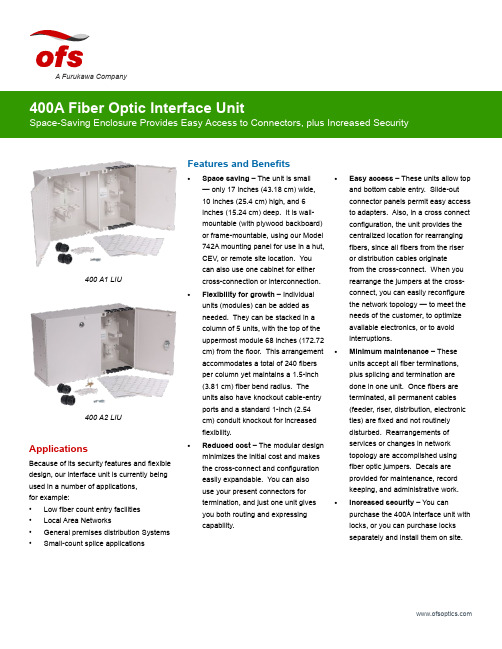
Features and Benefits•Space saving – The unit is small — only 17 inches (43.18 cm) wide, 10 inches (25.4 cm) high, and 6 inches (15.24 cm) deep. It is wall-mountable (with plywood backboard) or frame-mountable, using our Model 742A mounting panel for use in a hut, CEV, or remote site location. You can also use one cabinet for eithercross-connection or interconnection.•Flexibility for growth – Individual units (modules) can be added as needed. They can be stacked in a column of 5 units, with the top of the uppermost module 68 inches (172.72 cm) from the floor. This arrangement accommodates a total of 240 fibers per column yet maintains a 1.5-inch (3.81 cm) fiber bend radius. The units also have knockout cable-entryports and a standard 1-inch (2.54 cm) conduit knockout for increased flexibility.•Reduced cost – The modular design minimizes the initial cost and makes the cross-connect and configuration easily expandable. You can also use your present connectors for termination, and just one unit gives you both routing and expressing capability.•Easy access – These units allow top and bottom cable entry. Slide-out connector panels permit easy access to adapters. Also, in a cross connect configuration, the unit provides the centralized location for rearranging fibers, since all fibers from the riser or distribution cables originate from the cross-connect. When you rearrange the jumpers at the cross-connect, you can easily reconfigure the network topology — to meet the needs of the customer, to optimize available electronics, or to avoid interruptions.• Minimum maintenance – These units accept all fiber terminations, plus splicing and termination are done in one unit. Once fibers are terminated, all permanent cables (feeder, riser, distribution, electronic ties) are fixed and not routinely disturbed. Rearrangements of services or changes in network topology are accomplished using fiber optic jumpers. Decals are provided for maintenance, record keeping, and administrative work.• Increased security – You can purchase the 400A interface unit with locks, or you can purchase locks separately and install them on site.A Furukawa CompanyApplicationsBecause of its security features and flexible design, our interface unit is currently being used in a number of applications, for example:• Low fiber count entry facilities • Local Area Networks• General premises distribution Systems •Small-count splice applications400 A1 LIU400 A2 LIUget to them easily. And when you do, you must be confident that they have remained secure, just the way you left them — safe from unauthorized personnel. The OFS 400A Fiber Optic Interface Unit, provides both easy access and security.Developed by OFS Labs, the 400A interface unit is a modular enclosure that provides cross-connect and interconnect capabilities for splicing and terminating Outside Plant Cables (OSP) or Fiber Optic Building Cables.As shown below, the 400A interface unit has two separate side-by-side sections. One side houses terminated fibers; the other side houses organized jumpers. Each side has its own door with different keys. Although the unit comes in two models (400 A1 and 400 A2), the models are essentially identical. However, for greater security, Model 400A-2 has locks installed on each door.Cabinet Accessories12A1 Clamp – The 12A1 Cable Clamp is designed to provide means of securing one OSP cable inside the 400A interface unit. The clamp provides grounding for either ribbon cable equipped with sheath terminating hardware or stranded cable with metallic strength members. The 12A1 consists of a mounting bracket, plastic clamps, and suitable grounding lugs. It is recommended that two (2) 12A1s be installed inside the unit.12A2 Clamp – Clamp is similar to the 12A1 Clamp, but used with nonmetallic OSP cables.742A Panel – The panel can be mounted in either a 19 inch (48.26 cm) or 23 inch (58.42 cm) frame and gives the user the capabilities to install one (1) 400A interface unit in a stand-alone, interconnection or cross-connection configuration.This panel is an ideal panel to use when wall space is limited and frame space is available. It comes equipped with mounting screws, nuts and 742A mounting screws.D-181755 Direct Termination – This kit of parts is used to prepare OSP cable for direct termination of connectors in the 400A interface unit. It includes cable end prep materials and individual fiber protective buffer tubing.Fanout Assemblies – Order fanout for use with the 400A units. The fanout provides an easy transition from array connectorized ribbon cable to 12 individual fibers at the termination panels.Order fanouts with a 400A unit to provide easy transition from ribbon based cable to 12 individual connectors.The standard fanout consists of an array of connectorized ribbon which transitions into 12 individual, connectorized fibers.12A1 Clamp Kit742A PanelSC Mini FanoutA Furukawa CompanyFiber Splicing AccessoriesSplice kits are available in mass, single, or mechanical splicing configurations to expedite installation methods. Choose the desired splice kit for the first tray of splice organizers, then increase splicing count with additional supplemental trays.Recommended Growth Patternfor Interface UnitsWhen installing a cross-connect or interconnect configuration with top-entry cables, the recommended growth pattern is to install the first 400A interface unit at the top left corner of the allocated space. Any additional units should be placed beneath the first unit to create a column of up to five modules high.The number of units per column depends on the vertical dimension of the allocated space. The top of the highest module should not exceed 68 inches (172.72 cm) from the floor.Value StatementThe 400A Fiber Optic Interface Unit combines the latest in fiber optic technology with the latest in cabinet design. The space saving features and modular design of these units provide the flexibility you need for future growth — without the expense of replacing existing equipment. When you choose the 400A Fiber Optic interface unit from OFS, you get optimum equipment at minimum cost. It’s another one of OFS Labs innovations — keeping your network on the cutting-edge of fiber optic technology.LIU Mechanical Splice KitNumber of Trays Splices Adapter Ports0096 LC, 48 SC, 48 ST11296 LC, 48 SC, 48 ST22480 LC, 40 SC, 40 ST33664 LC, 32 SC, 32 ST Number of Trays Single FusionSplices Adapter Ports 0096 LC, 48 SC, 48 ST11696 LC, 48 SC, 48 ST23280 LC, 40 SC, 40 ST34864 LC, 32 SC, 32 STNumber of Trays Mass FusionSplices Adapter Ports 0096 LC, 48 SC, 48 ST1 6 (72)96 LC, 48 SC, 48 ST212 (144)80 LC, 40 SC, 40 ST318 (216)64 LC, 32 SC, 32 STTop EntryGrowthBottom EntryGrowthPossible Growth Sequences of a 240 Fiber X-Connect FieldA Furukawa CompanyKit LG-D181706LIU Mechanical Splice Kit Base Unit, has 1 Sup Tray108 915 141 Supplemental Mech. Splice Kit LIU Supplemental tray and organizer108 915 3641 AM1-12 LG Organizer Mechanical Organizer (12 mechanicals) part of Sup Tray (pack of10)105 356 570Kit LG-D181707LIU Single Splice Kit Base Unit, has 1 Sup Tray108 915 166 Supplemental Fusion Splice Kit LIU Supplemental Tray and Organizer108 915 356 1 AF1-16 LG Organizer Single Fusion Organizer (16 fusion) part of Sup Tray (pack of 10)105 356 562 Kit, Mass Fusion Splice LIU Mass Splice Kit Base Unit, has 1 Sup Tray300 386 976 Kit, Supplemental Fusion Splice LIU Supplemental tray and organizer300 386 984 Splice Holder, LG. Mass Fusion Mass Fusion Organizer (6 Mass fusion) fits Sup Tray (pack of 12)109 116 046 LIU Box AccessoriesProduct Code Description Comcode 742 A Panel100, 200, 400 Frame Mounting Panel108 915 182 Holder-1A1 Lightguide100, 200, 400 LIU Mini fanout holder for inside box108 919 283 Basic CabinetProduct Code Comcode 400 A1 Fiber Optic Interface Unit (w/o Locks)108 905 662 400 A2 Fiber Optic Interface Unit (with 2 Locks)108 905 670 7-inch Panels Used on 400 LIU Panels Pre-Loaded with AdaptersProduct Code Adapter Capacity Comcode 1000LC1W-SMPL-E/W 6 LC Simplex Adapters108 597 519 1000LC1W-DPL-E/W 6 LC Duplex Adapters108 597 527 1000LCA1W-DPL-E/W 6 Angled LC Duplex Adapters108 610 858 1000LCA1W-SMPL-E/W 6 Angled LC Simplex Adapters108 610 908 F91AK8515 ASSY 6 SC Adapters for MM or SM Use106 500 630 F91AK8514 ASSY 6 SM ST Adapters106 500 622 1000ST-C2000A-2 6 MM ST Adapters107 802 498 MWK-6 6 FC adapters106 225 923For additional information please contact your sales representative.You can also visit our website at or call 1-888-fiberhelp (1-888-342-3743) USA or 1-770-798-5555 outside the USA.OFS reserves the right to make changes to the prices and product(s) described in this documentat any time without notice. This document is for informational purposes only and is not intended to modify or supplement any OFS warranties or specifications relating to any of its products or services.Copyright © 2017 OFS Fitel, LLC. All rights reserved, printed in USA. OFS Marketing Communications DOC: fap-142 Date: 07/17A Furukawa Company7-inch Panels Used on 400 LIU Panels with Adapter Cutouts Only (No Adapters)Product CodeCutout CapacityComcode Reference Adapters (Note)1000LC1-SMPLX-6 6 LC Simplex Adapter Cutouts 108 365 685SM C1101A-1 107 764 2681000LC1-DPLX 6 LC Duplex Adapter Cutouts 108 365 693MM C1001B-2 108 072 497 or SM C1101A-2 108 072 4891000SC1 LG 3 SC Duplex Adapter Cutouts 106 372 121SM/MM-C6000A-5 107 022 980CONNLG-1000ST 6 ST Adapter Cutouts105 392 005MM-C2000A2 104 148 028 or SM-C3000A2 105 271 142CONNLG-1000ST LO 12 Pack of 6 ST Adapter Cutouts 105 428 486MM-C2000A2 104 148 028 or SM-C3000A2105 271 142CONNLG-1000FC/D4 6 FC/D4 Adapter Cutouts 105 428 254—1000BKBlank Panel (Package of 6)106 924 483—Note : These panels do not come equipped with adapters. To order the proper adapters for use with the panel, use the adapters listed in the ReferenceAdapters column that are associated with the ordered panel.A Furukawa Company。
华硕HFL Bluetooth HandsFreeLink 用户手册说明书
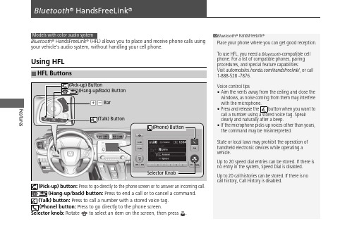
Features Bluetooth® HandsFreeLink® (HFL) allows you to place and receive phone calls usingyour vehicle's audio system, without handling your cell phone.Using HFL(Pick-up) button: Press to go directly to the phone screen or to answer an incoming call.(Hang-up/back) button: Press to end a call or to cancel a command.(Talk) button: Press to call a number with a stored voice tag.(Phone) button: Press to go directly to the phone screen.Selector knob: Rotate to select an item on the screen, then press .■HFL Buttons1Bluetooth® HandsFreeLink®Place your phone where you can get good reception.To use HFL, you need a Bluetooth-compatible cellphone. For a list of compatible phones, pairingprocedures, and special feature capabilities:Visit /handsfreelink/, or call1-888-528 -7876.Voice control tips•Aim the vents away from the ceiling and close thewindows, as noise coming from them may interferewith the microphone.•Press and release the button when you want tocall a number using a stored voice tag. Speakclearly and naturally after a beep.•If the microphone picks up voices other than yours,the command may be misinterpreted.State or local laws may prohibit the operation ofhandheld electronic devices while operating avehicle.Up to 20 speed dial entries can be stored. If there isno entry in the system, Speed Dial is disabled.Up to 20 call histories can be stored. If there is nocall history, Call History is disabled.Selector Knob(Phone) Buttonuu Bluetooth ® HandsFreeLink ®u Using HFLFeaturesThe audio/information screen notifies you when there is an incoming call.Certain manual functions are disabled or inoperable while the vehicle is in motion. You cannot select a grayed-out option until the vehicle is stopped.Only previously stored speed dial entries can be called using voice commands while the vehicle is in motion.■HFL Status Display1Bluetooth ® HandsFreeLink ®Bluetooth ® Wireless TechnologyThe Bluetooth ® word mark and logos are registered trademarks owned by Bluetooth SIG, Inc., and any use of such marks by Honda Motor Co., Ltd., is under license. Other trademarks and trade names are those of their respective owners.HFL LimitationsAn incoming call on HFL will interrupt the audio system when it is playing. It will resume when the call is ended.■Limitations for Manual Operation1HFL Status DisplayThe information that appears on the audio/information screen varies between phone models.uu Bluetooth® HandsFreeLink®u Using H FLFeatures■To pair a cell phone (No phone hasbeen paired to the system)1.Press the button or the button.2.Make sure your phone is in search ordiscoverable mode.3.Rotate to select Yes, then press .u The audio system will enter a waitingmode for pairing.4.Select HandsFreeLink® from your phone.u If you want to pair a phone from thisaudio system, press and follow theprompts.When your phone appears on the list,select it by pressing .5.The system gives you a pairing code on theaudio/information screen.u Confirm if the pairing code on the screenand your phone match.This may vary by phone.6.A notification appears on the screen ifpairing is successful.■Phone Setup1Phone SetupYour Bluetooth-compatible phone must be paired toHFL before you can make and receive hands-freecalls.Phone Pairing Tips:•You cannot pair your phone while the vehicle ismoving.•Up to six phones can be paired.•Your phone’s battery may drain faster when it ispaired to HFL.•If your phone is not ready for pairing or not foundby the system within 30 seconds, the system willtime out and return to idle.Once you have paired a phone, you can see itdisplayed on the screen with one or two icons on theright side.: The phone can be used with HFL.: The phone is compatible with Bluetooth® Audio.When pairing a phone from this audio system:If your phone doesn’t appear on the audio/information screen, select Refresh and search forBluetooth® devices using your phone.From your phone, select HandsFreeLink®.uu Bluetooth ® HandsFreeLink ®u Using H FLFeatures■To pair a cell phone (when a phone has1.Press the button or button.2.Rotate to select Yes , press .3.Rotate to select Add New Device , then press .4.Press to select OK .u The screen changes to device list.5.Make sure your phone is in search or discoverable mode, then press .u HFL automatically searches for a Bluetooth ® device.6.When your phone appears on the list, select it by pressing .u If your phone does not appear, select Refresh and search for Bluetooth ®devices using your phone.From your phone, select HandsFreeLink ®.7.The system gives you a pairing code on the audio/information screen.u Confirm if the pairing code on the screen and your phone match.This may vary by a phone.Features Bluetooth® HandsFreeLink® (HFL) allows you to place and receive phone calls usingyour vehicle’s audio system, without handling your cell phone.Using HFL■HFL Buttons1Bluetooth® HandsFreeLink®Place your phone where you can get good reception.To use HFL, you need a Bluetooth-compatible cellphone. For a list of compatible phones, pairingprocedures, and special feature capabilities:Visit /handsfreelink/, or call1-888-528 -7876.To use the system, the Bluetooth On/Off Statussetting must be On. If there is an active connection toApple CarPlay TM or Android Auto TM, HFL isunavailable.Voice control tips•Aim the vents away from the ceiling and close thewindows, as noise coming from them may interferewith the microphone.•Press the button when you want to call anumber using a stored voice tag, a phonebookname, or a number. Speak clearly and naturallyafter a beep.•If the microphone picks up voices other than yours,the command may be misinterpreted.•To change the volume level, select the audiosystem’s VOL (Volume) or use the remote audiocontrols on the steering wheel.Up to three speed dial entries can be displayedamong a total of 20 that can be entered.Up to three previous calls can be displayed at a timeamong a total of 20 that can be entered. If there is nocall history, Call History is disabled.(Talk) ButtonBar(Hang-up/Back) Button(Display/Information) Buttonuu Bluetooth ® HandsFreeLink ®u Using HFLFeatures(Pick-up) button: Press to go directly to the phone menu on the driver information interface, or to answer an incoming call.(Hang-up/back) button: Press to end a call, go back to the previouscommand, or cancel a command.(Talk) button: Press to access Voice Portal. buttons: Press to select an item displayed on the phone menu in the driver information interface.ENTER button: Press to call a number listed in the selected item on the phone menu in the driver information interface.(display/information) button: Select and press ENTER to display Speed Dial , Call History , orPhonebook on the phone menu in the driver information interface.To go to the Phone Menu screen:1.to switch the display to the phone screen.2..1Bluetooth ® HandsFreeLink ®Bluetooth ® Wireless TechnologyThe Bluetooth ® word mark and logos are registered trademarks owned by Bluetooth SIG, Inc., and any use of such marks by Honda Motor Co., Ltd., is under license. Other trademarks and trade names are those of their respective owners.HFL LimitationsAn incoming call on HFL will interrupt the audio system when it is playing. It will resume when the call is ended.34uu Bluetooth ® HandsFreeLink ®u Using HFLFeaturesThe audio/information screen notifies you when there is an incoming call.Certain manual functions are disabled or inoperable while the vehicle is in motion. You cannot select a grayed-out option until the vehicle is stopped.Only previously stored speed dial entries with voice tags, phonebook names, or numbers can be called using voice commands while the vehicle is in motion.■HFL Status Display1HFL Status DisplayThe information that appears on the audio/information screen varies between phone models.■Limitations for Manual Operationuu Bluetooth ® HandsFreeLink ®u Using H FLFeatures■To pair a cell phone (when there is no1.Select2..3.Make sure your phone is in search or discoverable mode.4.Select HandsFreeLink from your phone.u If you want to pair a phone from this audio system, select HandsFreeLink Not Found , Continue , and then select your phone when it appears on the list. If your phone does not appear, you can select Refresh to search again.5.The system gives you a pairing code on the audio/information screen.u Confirm if the pairing code on the screen and your phone match.This may vary by phone.6.A notification appears on the screen if pairing is successful.u You can prioritize a Bluetooth ® device at the same time. Select Yes and then a device you want to prioritize.■Phone Setup1Phone SetupYour Bluetooth -compatible phone must be paired to the system before you can make and receive hands-free calls.Phone Pairing Tips:•You cannot pair your phone while the vehicle is moving.•Up to six phones can be paired.•Your phone's battery may drain faster when it is paired to the system.•If your phone is not ready for pairing or not found by the system within three minutes, the system will time out and return to idle.Once you have paired a phone, you can see itdisplayed on the screen with one or two icons on the right side.These icons indicate the following:: The phone can be used with HFL.: The phone is compatible with Bluetooth ® Audio.If there is an active connection to Apple CarPlay , TM pairing of additional Bluetooth -compatible devices is unavailable.uu Bluetooth® HandsFreeLink®u Using H FLFeatures ■To change the currently paired phone1.Go to the phone settings screen.2.Select Bluetooth Device List.3.Select a phone to connect.u HFL disconnects the connected phoneand starts searching for another pairedphone.4.Selector■1.Select2..3.Select Bluetooth / Wi-Fi.4.Select the Bluetooth tab.5.Select Edit Pairing Code.6.Select Random or Fixed.1To change the currently paired phoneIf no other phones are found or paired when trying toswitch to another phone, HFL will inform you that theoriginal phone is connected again.To pair other phones, select Add Bluetooth Devicefrom the Bluetooth Device List screen.To change the Bluetooth® connection priority devicesetting, select Priority Device Settings from theBluetooth Device List screen.1To change the pairing code settingThe default pairing code is 0000 until you change thesetting.To create your own, select Fixed, and delete thecurrent code, then enter a new one.For a randomly generated pairing code each time youpair a phone, select Random.uu Bluetooth ® HandsFreeLink ®u Using H FLFeatures■Automatic collision notificationIf your vehicle’s airbags deploy or if the unit detects that the vehicle is severely impacted, your vehicle automatically will attempt to connect to the HondaLink operator. Ifconnected, information about your vehicle, its location, and its condition can be sent to the operator ; you also can speak to the operator *1when connected.IMPORTANT: For vehicles equipped with HondaLink Assist, owner activationconstitutes authorization for Honda to collect information from your vehicle needed to provide the service, and agreement to the Terms of Use at/TermsAndConditions . In a crash, HondaLink Assist will attempt to notify emergency services but NEITHER Honda-PRO NOR ITS SERVICE PROVIDERS GUARANTEE THAT SUCH NOTIFICATION WILL OCCUR.Honda reserves the right to terminate HondaLink Assist services at any time or for any reason, and in the future may not be able to provide services due to changes in, or obsolescence of, technology integral to the service or changes in governmental regulation.*1: Depending on your phone and adequate cellular coverage, your vehicle's location may not be sent to the operator.■In Case of Emergency1In Case of EmergencyYour vehicle may not be able to connect to the operator if the battery level is low, the line isdisconnected, or you do not have adequate cellular coverage.You cannot use this emergency service when:•You travel outside the HondaLink service coverage areas.•There is a problem with the connecting devices,such as the microphones, speakers, or the unit itself.You cannot operate other phone-related functions using the screen while talking to the operator.Select Hang Up to terminate the connection to your vehicle.1Automatic collision notificationIf the unit fails to connect to the operator, it repeatedly tries until it succeeds.uu Bluetooth® HandsFreeLink®u Using H FLFeatures ■To enable notification1.Go to the Phone Settings screen.2.Select the Phone tab, then HondaLinkAssist.u A pop-up menu appears on the screen.3.Select On or Off.1To enable notificationSetting options:•On: Notification is available.•Off:Disable the feature.。
华硕 笔记本电脑 用户手册说明书

目录版权和商标声明 ............................................................................................................1-4修订 ..............................................................................................................................1-4FCC-B 频道干扰声明....................................................................................................1-5FCC 规定......................................................................................................................1-5CE 规定 ........................................................................................................................1-6电池规范 .......................................................................................................................1-6WEEE 声明...................................................................................................................1-6化学物质法规................................................................................................................1-7升级和保修 ..................................................................................................................1-7购买备件 .......................................................................................................................1-7安全指南 .......................................................................................................................1-8产品中有害物质的名称及含量.....................................................................................1-10MSI 特殊功能 .............................................................................................................1-11简介 ...............................................................................................2-1打开包装 .......................................................................................................................2-2产品检视 .......................................................................................................................2-3顶盖开启检视图 .......................................................................................................2-3前端检视图 ..............................................................................................................2-5右端检视图 ..............................................................................................................2-6左端检视图 ..............................................................................................................2-7后端检视图 ..............................................................................................................2-8底部检视图 ..............................................................................................................2-9如何使用键盘..............................................................................................................2-11Windows 键 ...........................................................................................................2-11快速启动按键.........................................................................................................2-12开启或关闭触摸板..................................................................................................2-13进入睡眠模式.........................................................................................................2-13切换显示器 ............................................................................................................2-13使用多个监视器 .....................................................................................................2-13调整显示器的亮度 .................................................................................................2-14调整扬声器的音量..................................................................................................2-14调整键盘背光 LED 灯的亮度(选择性配置) ........................................................2-14应用程序:True Color (选择性配置) ......................................................................2-15产品规格 .....................................................................................................................2-16使用者手册如何使用入门 .................................................................................3-1开始使用笔记本电脑 .....................................................................................................3-2如何舒适地使用笔记本电脑 ..........................................................................................3-3如何使用电源供应器 .....................................................................................................3-4电源适配器 ..............................................................................................................3-4电池 .........................................................................................................................3-4如何在 Windows 10 下设置一个电源计划设定 .............................................................3-6选择或自定义电源计划 ............................................................................................3-6创建自己的电源计划 ................................................................................................3-9如何使用触摸板 .........................................................................................................3-11了解一般硬盘和固态硬盘............................................................................................3-12了解 M.2 固态硬盘插槽...............................................................................................3-12如何连接 Internet........................................................................................................3-13无线网络 ................................................................................................................3-13有线网络 ................................................................................................................3-15如何设置蓝牙连接.......................................................................................................3-20开启蓝牙连接.........................................................................................................3-20如何连接外部装置.......................................................................................................3-23视频:如何使用 RAID 功能 ........................................................................................3-24如何在 BIOS 中选择 Boot Mode.................................................................................3-25视频:如何在 MSI 笔记本电脑上恢复 Windows 10 操作系统.....................................3-26视频:如何使用 MSI 一键安装 ..................................................................................3-27版权和商标声明Copyright © 微星科技股份有限公司所有。
华硕电脑手册说明书

Important NoticesImproper handling of a vehicle , especially while raised and supported by jack stands, ramps or other mechanical means, can cause serious bodily injury or even death. It is strongly rec-ommended that a trained, experienced mechanic, with proper equipment, do the installation.The seller nor the manufacturer assumes no liability, expressed or implied, for the improper installation or use of this product or its components. Before using, the user shall determine the suitability of the products for it’s intended use. The user assume all responsibility and risk in connection there within.It is the buyer’s responsibility to have all suspension, drivetrain, steering, and other compo-nents checked for proper tightness and torque after the fi rst 100 miles and every 3,000 miles by a qualifi ed professional mechanic.Extreme care should be taken while operating your vehicle to prevent vehicle rollover or loss of control. Both can result in serious injury or death. Do not add or modify parts to this kit or use outside it’s intended purpose. Follow all safety regulations and warnings per state and federal laws.Note: Final fi tment of the wheel to caliper is the responsibility of the customer.Note: It is important to read and understand this ENTIRE installation manual, before starting the installation.Kit Contents1 Pair of calipers w/pads2 Rotors2 Retaining plate2 Preload spacers (C-clip applications)4 Caliper bolts8 T-bolts8 Nuts2 Disc brake mounting plate assembly (1 Left and 1 Right)1 stainless steel brake line kitTools and Equipment That May Be RequiredDifferent models and years of vehicle use different-sized fasteners, and every effort has been taken to correctly identify the proper sized tool for each step of the installation. Occasionally, however, manufacturers use alternate fasteners, so it’s advisable to check that each tool cor-rectly fi ts the fastener before loosening or tightening it. The following tools and equipment may be needed:9/16” socket wrench12mm socket14mm wrenchTorque wrenches capable of 10-148 lb-ft settingsSeveral ragsSmall funnel or suitable means of fi lling master cylinder reservoirBrake bleed bottle1 pair of jack stands or other means of supporting vehicleHydraulic pressPair of PliersStep 1-Remove WheelsWARNING - Brake fl uid will damage most painted surfaces. Immediately clean spilled brake fl uid from any painted surfaces. Be sure the cap is securely installed on the master cylinder. If the cap is loose or removed, it is likely more fl uid willdrip.Note: All Photographs Show Left Side Installation, unless noted otherwise.Break loose the lug nuts on both rear wheels before jacking up the car.Refer to the Owners Manual for the correct location when jacking up the vehicle. Jack up the vehicle and secure on a pair of jack stands. Never leave any vehicle supported with only a jack - always use jack-stands.After securing the vehicle at a convenient height, remove the rear wheels.Note: If you remove the bottom lug nut last while holding the bottom of the tire, it will lessen the chances of the wheel tilting on it’s own and make removal easier.Step 2 -Removal of Drum Brakes and AxleRemove brake drums from thebrake assembly.Remove the hard line from thewheel cylinder attached to thebacking plate.For c-clip applications- Removethe differential cover, unbolt thecross shaft and remove it from thevehicle. See factory service manualfor additional information.Using a 9/16” socket, remove thefour nuts that hold each axle shaftinto the axle and remove the axleshafts from the axle. Some leakagemay occur.Remove the backing plate from theaxle housing.Wipe clean grease and contami-nants from all surfaces.For semi-fl oat applications- Pressthe old bearings and seals fromthe axle shafts. C-clip applicationsdo not need the removal of the oldbearings and seals unless parts areneeded to be replaced.Install the disc brake mounting plate onto the axle flange with new supplied retaining bolts. The mounting plate is directional, insurethat the plate is installed on the correct side.Step 3 -Install Disc Mounting PlateIn order to install this kit, remove the factory bolts from the axle fl ange. If installing on a C-clip application do not remove the fac-tory bolts.Install the supplied bolts (longer than factory bolts) in the axle fl ange.Adjust the internal parking brake shoes with the adjuster until there is just enough room to slide the ro-tor over the shoes. Refer to the fac-tory service manual for additional information.STEP 4 -Install Axle ShaftsApply grease to the outside of the bearing seal assembly and slide the preload spacer onto the seal. The grease will help hold the spacer in place.Slide the axle shaft into the axle housing by hand, lining it up with the differential. The axle shaft should not be forced, damage mayoccur.On C-clip retained axles, slide the axles all the way into the axle hous-ing using care to avoid damage to the splines or the bearing surface. Reinstall the C-clip and the cross shaft. Ensure that all old silicone is cleaned from the differential hous-ing and the differential cover, and reinstall the differential cover using a new gasket or silicone. Fill thehousing with new oil.Using a hydraulic press, press the new bearing and retaining collar onto the axle shaft. Refer to the factory service manual for more details.Grease the shaft where the axle shaft seal will be installed, theninstall the seal.Install the retaining plate and new preload spacer on axle shaft. Notice the direction the preload spacer is facing in the photo to the right. The chamfer side faces inboard.STEP 5 -Install the Rotor and CaliperInstall the rotor on the axle.Install the brake pads in the caliper.Using a 12mm socket wrench in-stall the caliper onto the mounting plate. Torque the bolts to 15-18 ft-lbs.Line up the access holes located on the axle shafts with the retainer bolts. Using a 9/16” socket wrench tighten the four nuts to 25 - 30 ft-lbs.STEP 4 -(Continued)Install Axle ShaftsSTEP 6 -Install Stainless Steel Brake LinesInstall the caliper end of the stainless steel brake line by fi rst placing a copper crush washer on either side of the banjo fi tting.Insert the banjo bolt into the caliper using a 14mm wrench or socket to tighten it. Insert the stainless steel brake line fi tting through the chassis bracket, and screw it onto the hard line fi tting by hand a few turns, to ensure that it is properly engaged. Tighten the hard line fi tting.Check to ensure that the brake line is not binding in any way, nor interfering with any suspension component.Note that you will need to purchase shorter metal brake lines from an automotive pats supplier.If the brake line is not properly routed, a catastrophic failure could occur. If you are unsure that the line is routed properly and safely, do not drive the car. Please call our Tech Support Dept. for assistance if you have any doubt as to the brake line routing.Install the emergency brake cable at the mounting plate and adjust, refer to the factory service manual.If realignment is necessary, loosen the banjo bolt, and realign the brake line, or loosen the inboard end of the line, and slightly re-clock the fitting.Weld the brake line mounting tab onto the axle tube. Install the brake line through the tab and install the c-clip to secure the line.STEP 7-Bleed BrakesComplete installation on both sides of the vehicle before bleeding the system. Note: The calipers and lines will need to fi ll with fl uid, quickly draining the master cylinder reservoir. Keep a close watch on the fl uid level when initially bleeding the system. Do not allow the master cylinder reservoir to run dry and draw in air. Doing so may require the brake system to be serviced by a certifi ed brake technician.Refer to owners manual for torque used on bleed screws.After initially bleeding the system, gently tap the caliper body with a non-marring mallet or hammer to dislodge any small air bubbles and re-bleed.After bleeding, apply a constant pressure to the brake pedal and check all connections, including bleed screws, and both ends of the line for leaks.Brake fl uid will damage most painted surfaces. Immediately clean spilled brake fl uid from any painted surface, including the caliper. Though caliper paint is designed to resist harsh chemicals, prolonged exposure will damage the fi nish.STEP 8-Reinstall wheelsCheck wheel to caliper clearance before installing wheels!Reinstall the wheels and torque the lug nuts to your wheel manufacturer’s specifi cations. It may be necessary to snug the bolts before lowering the vehicle and then torque the wheels when the car is on the ground. Alternatively, an assistant may depress the brake pedal while you tighten the wheel nuts to the proper torque setting.Carefully test-drive the vehicle in a safe area at low speed to insure all components are working correctly.。
华硕 TUF H370-PRO GAMING 主板用户手册说明书

地址:Harkort Str. 21-23, D-40880 Ratingen, Germany
傳真:+49-2102-959931 互聯網:/de 在線聯絡:/sales(僅回
答市場相關事務的問題)
電話:+49-2102-5789555 傳真:+49-2102-959911 在線支持:/techserv
華碩的聯絡信息
華碩電腦(上海)有限公司 ASUSTEK COMPUTER (SHANGHAI) CO., LTD
行區金都路 5077 號 電話:+86-21-54421616 傳真:+86-21-54420088 互聯網:/
Address: 800 Corporate Way, Fremont, CA 94539. Phone/Fax No: (510)739-3777/(510)608-4555 hereby declares that the product Product Name : Motherboard Model Number : TUF H370-PRO GAMING,
11. D-sub 接口 12. USB 2.0 接口
主板安裝及使用
安裝前的準備
在安裝主板之前,請準備必要的工具。
欲了解安裝主板需準備的工具,及開機通電等詳 細內容,請掃描右側二維碼。
中央處理器(CPU)
本主板配備一組中央處理器插槽,支持採用 LGA1151 規格插槽的第八代英特爾® 酷睿™ 處理器。
傳真:+1-510-608-4555 互聯網:/us/
電話:+1-812-282-2787 傳真:+1-812-284-0883 在線支持:/techserv
ASUS COMPUTER GmbH(德國/奧地利)
华硕P7H55-M_USB3用户手册

三年質保
全國聯保
請用剪刀沿虛線剪下
華碩產品質量保證卡
尊敬的華碩產品用戶:
首先非常感謝您選用華碩公司產品,讓我們有機會向您提供優質的服務。為了使我們的服務讓您 更滿意,在購買後請您認真閱讀此說明並妥善保存此質量保證卡。
保修說明注意事項:
一、 請將此質量保證卡下方的用戶資料填寫完整,並由最終直接經銷商加蓋印章,如果沒有加蓋印 章,請找原購買處補蓋以保障您的權益。請務必保留購買發票或複印件,否則華碩公司將以產 品的出廠日期為參照進行保修。
或認可之配件所引起之故障與損壞。 D. 因用戶自行安裝軟件及設定不當所造成之使用問題及故障。 E. 計算機病毒所造成之問題及故障。 F. 本公司保修識別標籤撕毀或無法辨認,涂改保修服務卡或與產品不符。 G. 要求華碩提供軟件安裝服務(用戶需自行提供原版軟件)、軟件故障排除或清除密碼等。 H. 其它不正常使用所造成之問題及故障。
用戶名稱
購買日期
用 聯繫人
戶 聯繫地址
填 經銷商名稱 寫 資 產品型號
料
經
銷
商
印
章
聯繫電話
產品種類 產品序號
目錄內容
安全性須知.................................................................................................................................. viii 電氣方面的安全性......................................................................................................... viii 操作方面的安全性......................................................................................................... viii 華碩 REACH................................................................................................................... viii
华硕Thermo-hygrometer用户手册说明书

12345Thermo-hygrometerDescription of the device1. OK key2. Backlight key3. Select key4. On/Off/Esc key5. Hold/min/max keyHD 110Technical specificationsGeneral features(1)All the accuracies indicated in this technical datasheet were stated in laboratory conditions, and can be guaranteed for measurements carried out in the same conditions, or carried out with calibration compensation.Once the measurement is frozen:• Press “Hold/min/max”.• The device displays the maximum value of hygrometry measured since the last questioning at the top of the screen and the minimum value of hygrometry measured since the last questioning at the bottom of the screen.• Press “Hold/min/max”.• The device displays the maximum value of temperature measured since the last questioning at the top of the screen and the minimum value measured since the last questioning at the bottom of the screen.• Press again “Hold/min/max”.• The device displays the maximum value of dew point measured since the last questioning at the top of the screen and the minimum value of dew point measured since the last questioning at the bottom of the screen.• Press “On/Off/Esc” to return to the measurements display.Display the minimum and the maximum• Turn on the device by pressing on “On/Off/Esc”. The device displays its name “HD110” then the measured values.• Put the probe to the required location.The device displays the temperature and hygrometry measurements.• Press “OK”.The device displays the dew point measurement with the temperature measurement.• Press again on “OK”.•The device displays the dew point measurement with the hygrometry measurement.Perform a measurementDuring the measurement:• Press “Hold/min/max” to freeze the measurement.“Hold” displays on screen and the measurements are frozen.• Press “On/Off/Esc” to exit the hold function. The device returns to the measurements display.Freeze the measurement Adjust the device Device drop-down menuSelect the measuring unit • Press “Select”.“UNIT” blinks on screen.• Press “OK”, the measuring unit currently used blinks at the bottom of the screen.• Press “Select” to select the required measuring unit: °C or °F .• Press“OK” to validate. “UNIT” blinks on screen.•Press “On/Off/Esc” to return to the measurement.Adjust the auto shut-offThe device is on and displays the measurements.• Press “Select” until “AUTO OFF” blinks on screen.• Press “OK”.The time before auto shut-off blinks on screen.• Press “Select” to select the time before device auto shut-off: 15, 30, 45, 60, 75, 90, 105, 120 minutes or OFF.• Press “OK” to validate.• Press “On/Off/Esc” to return to the measurement.Activate or deactivate the keys beep• The device is on and displays the measurements.• Press “Select” until “BEEP” blinks on screen.• Press “OK”.“OFF” or “ON” blinks on screen.• Press “Select” to activate the keys beep “ON” or deactivate the keys beep “OFF”.• Press “OK” to validate.•Press “On/Off/Esc” to return to the measurement.• Press on “Backlight” to activate the device backlight.• To deactivate the backlight press again on “Backlight”.Activate the backlight• Remove the front part at the back of the device.• Change the old batteries by AAA LR03 1.5 V batteries.• Replace the front part.Change the batteriesN T _E N – H D 110 – 10/11/17– N o n -c o n t r a c t u a l d o c u m e n t – W e r e s e r v e t h e r i g h t t o m o d i f y t h e c h a r a c t e r i s t i c s o f o u r p r o d u c t s w i t h o u t p r i o r n o t i c e .。
华硕 ROG Zephyrus M16 GU603 笔记本电脑 使用手册说明书

DRAGON CENTER 适用于电竞笔记本2目录关于 DRAGON CENTER (5)DRAGON CENTER 基础知识 (6)主界面 (6)信息栏 (6)主菜单 (7)子菜单 (7)Game 优化 (8)Gaming 模式 (8)Gaming 模式选项 (8)如何在 Gaming 模式加入游戏 (9)如何从 Gaming 模式移除游戏 (10)如何启用 Gaming 模式 (11)User Scenario (用户场景) (12)选择用户场景 (12)OC 选项 (13)General Settings (常规设置) (15)Monitor (监视器) (16)Game Highlights (17)如何将精彩游戏重播分享到社交媒体 (18)如何删除游戏影片 (19)安装 MSI Companion (20)配置 MSI Companion (22)如何发现 MSI Companion (24)设置 Game Highlights (25)True Color (27)True Color 预设选项 (27)Mystic Light (动态 RGB LED 炫光系统) (28)Voice Command 语音控制 (31)Noise Cancellation (噪音消除) (37)Duet Display (38)创建新的屏幕配置文件 (39)激活分屏截取 (39)电竞装备 (40)产品注册 (41)Live Update (实时更新) (42)3目录System Info (系统信息) (43)Microsoft APP (微软应用程序) (44)Battery Master (电池大师) (45)校准电池 (45)Backup (备份) (46)常规事项 (47)版权声明 (47)修订 (47)4目录关于 DRAGON CENTER∙优化游戏设置,享受高品质的游戏体验。
∙系统性能调整,可以选择超频或静音。
华硕 ROG STRIX XG17AHP 便携式游戏显示器用户手册说明书

ROG STRIX XG17AHP Portable GamingMonitorUser GuideCopyright © 2020 ASUSTeK COMPUTER INC. All Rights Reserved.No part of this manual, including the products and software described in it, may be reproduced, transmitted, transcribed, stored in a retrieval system, or translated into any language in any form or by any means, except documentation kept by the purchaser for backup purposes, without the express written permission of ASUSTeK COMPUTER INC. (“ASUS”).Product warranty or service will not be extended if: (1) the product is repaired, modified or altered, unless such repair, modification of alteration is authorized in writing by ASUS; or (2) the serial number of the product is defaced or missing.ASUS PROVIDES THIS MANUAL “AS IS” WITHOUT WARRANTY OF ANY KIND, EITHER EXPRESS OR IMPLIED, INCLUDING BUT NOT LIMITED TO THE IMPLIED WARRANTIES OR CONDITIONS OF MERCHANTABILITY OR FITNESS FOR A PARTICULAR PURPOSE. IN NO EVENT SHALL ASUS, ITS DIRECTORS, OFFICERS, EMPLOYEES OR AGENTS BE LIABLE FOR ANY INDIRECT, SPECIAL, INCIDENTAL, OR CONSEQUENTIAL DAMAGES (INCLUDING DAMAGES FOR LOSS OF PROFITS, LOSS OF BUSINESS, LOSS OF USE OR DATA, INTERRUPTION OF BUSINESS AND THE LIKE), EVEN IF ASUS HAS BEEN ADVISED OF THE POSSIBILITY OF SUCH DAMAGES ARISING FROM ANY DEFECT OR ERROR IN THIS MANUAL OR PRODUCT.SPECIFICATIONS AND INFORMATION CONTAINED IN THIS MANUAL ARE FURNISHED FOR INFORMATIONAL USE ONLY, AND ARE SUBJECT TO CHANGE AT ANY TIME WITHOUT NOTICE, AND SHOULD NOT BE CONSTRUED AS A COMMITMENT BY ASUS. ASUS ASSUMES NO RESPONSIBILITY OR LIABILITY FOR ANY ERRORS OR INACCURACIES THAT MAY APPEAR IN THIS MANUAL, INCLUDING THE PRODUCTS AND SOFTWARE DESCRIBED IN IT.Products and corporate names appearing in this manual may or may not be registered trademarks or copyrights of their respective companies, and are used only for identification or explanation and to the owners’ benefit, without intent to infringe.Table of contentsNotices .........................................................................................................iii Safety information ......................................................................................iv Care & cleaning ............................................................................................v Takeback services .. (vi)1.1 Welcome! ......................................................................................1-11.2Package contents .........................................................................1-11.3Monitor introduction ....................................................................1-21.3.1 Front View and Charging Instructions .............................1-22.1Monitor standing positions .........................................................2-12.2Connect the USB monitor with system ......................................2-22.3Assembling/Dis-assembling the ROG tripod ............................2-32.4How to Adjust tilt strength of ROG Tripod ................................2-32.5 Announcements ...........................................................................2-53.1 OSD (On-Screen Display) menu .................................................3-13.1.1 How to reconfigure ..........................................................3-13.1.2 OSD Function Introduction ..............................................3-23.2 Specifications .............................................................................3-103.3 Troubleshooting (FAQ) ..............................................................3-113.4Supported Timing List ...............................................................3-12NoticesFederal Communications Commission StatementThis device complies with Part 15 of the FCC Rules. Operation is subject to the following two conditions:• This device may not cause harmful interference, and• This device must accept any interference received including interference that may cause undesired operation.This equipment has been tested and found to comply with the limits for a Class B digital device, pursuant to Part 15 of the FCC Rules. These limits are designed to provide reasonable protection against harmful interference in a residential installation. This equipment generates, uses and can radiate radio frequency energy and, if not installed and used in accordance with the instructions, may cause harmful interference to radio communications. However, there is no guarantee that interference will not occur in a particular installation. If this equipment does cause harmful interference to radio or television reception, which can be determined by turning the equipment off and on, the user is encouraged to try to correct the interference by one or more of the following measures:• Reorient or relocate the receiving antenna.• Increase the separation between the equipment and receiver.• Connect the equipment to an outlet on a circuit different from that to which the receiver is connected.• Consult the dealer or an experienced radio/TV technician for help. Canadian Department of Communications StatementThis digital apparatus does not exceed the Class B limits for radionoise emissions from digital apparatus set out in the Radio Interference Regulations of the Canadian Department of Communications.This class B digital apparatus complies with Canadian ICES-003.Safety information• Before setting up this Portable Gaming Monitor, carefully read all the documentation that came with the package.• To prevent fire or shock hazard, never expose this Portable Gaming Monitor to rain or moisture.• Never try to open this Portable Gaming Monitor cabinet.• Before using this Portable Gaming Monitor, make sure all cables are correctly connected and the power cables are not damaged. If youdetect any damage, contact your dealer immediately.• Avoid dust, humidity, and temperature extremes. Do not place this Portable Gaming Monitor in any area where it may become wet. Place this Portable Gaming Monitor on a stable surface.• Never push objects or spill liquid of any kind into the slots on this Portable Gaming Monitor cabinet.• If you encounter technical problems with this Portable Gaming Monitor, contact a qualified service technician or your retailer.• This Portable Gaming Monitor is powered by USB port which complies with LPS and SELV circuit according to IEC60950-1:2005.• DO NOT dispose of the product in fire• DO NOT use monitor near heating equipment or in places where there is likelihood of high temperature• Keep your monitor away from sharp objects• DO NOT place objects on top of your monitorCare & cleaning• Cleaning. Turn your monitor off and unplug the cable. Clean the monitor surface with a lint-free, non-abrasive cloth. Stubborn stainsmay be removed with a cloth dampened with mild cleaner.• Avoid using a cleaner containing alcohol or acetone. Use a cleaner intended for use with the LCD. Never spray cleaner directly on thescreen, as it may drip inside the monitor and cause an electric shock. The following symptoms are normal with the monitor:• You may find slightly uneven brightness on the screen depending on the desktop pattern you use.• When the same image is displayed for hours, an afterimage of the previous screen may remain after switching the image. The screen will recover slowly or you can turn off the Power Switch for hours.• When the screen becomes black or flashes, or cannot work anymore, contact your dealer or service center to fix it. Do not repair the screen by yourself!Conventions used in this guideWARNING: Information to prevent injury to yourself when trying tocomplete a task.CAUTION: Information to prevent damage to the componentswhen trying to complete a task.IMPORTANT: Information that you MUST follow to complete atask.NOTE: Tips and additional information to aid in completing a task.Where to find more informationRefer to the following sources for additional information and for product and software updates.1. ASUS websitesThe ASUS websites worldwide provide updated information on ASUS hardware and software products. Refer to 2. Optional documentationYour product package may include optional documentation that may have been added by your dealer. These documents are not part ofthe standard package.Takeback servicesASUS recycling and takeback programs come from our commitment to the highest standards for protecting our environment. We believe in providing solutions for our customers to be able to responsibly recycle our products, batteries and other components as well as the packaging materials. Please go to /english/Takeback.htm for detail recycling information in different region.1.1 Welcome!Thank you for purchasing the ASUS® Portable Gaming Monitor!The latest ASUS Portable Gaming Monitor provides great portability and simplicity to your daily life, enhancing both of your viewing experience and style.1.2 Package contentsCheck your package for the following items:Portable Gaming MonitorQuick Start GuideWarranty CardUSB Type-C CableSmart CoverUSB Type-C to A AdapterMicro HDMI to HDMI cablePower AdapterROG TripodROG Carry Bag• If any of the above items is damaged or missing, contact your retailerimmediately.1.3Monitor introduction 1.3.1Front View and Charging Instructions1.Power button/Power LED •Press this button to turn the monitor on/off when connected to a valid source.• The color definition of the power indicator is as the below table. 2.MENU Button:•Press this button to enter the OSD menu.•Long pressing the button allows you to have a quick check on battery % even the device is OFF.3.Close Button •Exit the OSD menu.4.•Adjust the volume level.•Key Lock shortcut key. Press and hold it for 5 seconds to enable/disable Keys Lock.5. Micro-HDMI port •Connect your computer with Micro-HDMI cable.6. USB Type-C port• Used to connect to a valid source such as Notebook/PC/Mobile phone that supports USB Type C DP Alt Mode; signal input supports maximumto resolution 1920 x 1080 @240Hz.• Used to do battery charging; up to 9V@2A 18W power supply by **************************************************adapters on the market.7. USB Type-C port• Used to do battery charging; up to 9V@2A 18W power supply by **************************************************adapters on the market.8. Earphone - out PortIMPORTANT:• Charge the monitor for 4 hours before using it for the first time• Use only bundled power adapter and USB cable to charge yourmonitor. Using different power adapter and cable might bring potentialdamage to your device.WARNING: The adapter may become warm to hot while in use.DO NOT cover the adapter and keep it away from your body whileit is connected to a power source. If your device become unusualhot, disconnect the USB cable from your device and send thedevice including the power adapter and USB cable to an ASUSqualified service personnel2.1 Monitor standing positionsYou can stand up the monitor by several positions with the smart cover.2.2 Connect the USB monitor with systemBCD2.3 Assembling/Dis-assembling the ROG tripod132.4 How to Adjust tilt strength of ROG TripodThe tilt strength is adjustable according to personal habits.Depends on the usage, the tilt strength could get loose as used frequency gets more , you can also follow below steps to do the adjustment.After adjusting the tilt strength by inbox Allen wrench, following below to assemble ball shaft backNOTE:• ROG tripod can be the stand for products that implement standardtripod hole.• When the ball shaft is removed, it becomes a standard tripod, astandard 1/4 thread is seen embedded.• ROG tripod can only support product that is within 1.5kg, please don’tconnect with product that is over this weight.2.5 AnnouncementsAs this product and attached smart cover includes magnet in the structure, there could be potential risk to cause the damage of computer hard disc and objects that are sensitive to magnet.Please ensure not to stack the product with the computer when computer is in use (power on or standby mode) otherwise the hard drive could possibly be influenced by the result of permanent data missing or the computer display could be switched off due to computer auto protection mechanism. When place this product together with computer in the bag, must have the computer power off to avoid possible hard drive damage problem.(Check Picture A)The battery capacity will vary depending on the environment temperature, humidity, and monitor usagePicture A3.1OSD (On-Screen Display) menu3.1.1How to reconfigure1. Press the MENU button to activate the OSD menu.2.Press the ❑ and ☐ buttons to toggle between options in theMenu. As you move from one icon to another, the option name is highlighted.3. To select the highlighted item on the menu press the button.4. Press the ❑ and ☐ buttons to select the desired parameter.5.Press the button to enter the slide bar and then use the ❑ or ☐ buttons, according to the indicators on the menu, to make your changes.6.to return to previous menu or to accept and return to previous menu.• :Get power from source when this icon is shown • :Battery power•:Battery is being charged3.1.2 OSD Function Introduction1. GamingThis function contains OD, Adaptive-Sync/Free-Sync, GamePlus, GameVisual, Shadow Boost.• Level 0~Level 5.•Adaptive-Sync/FreeSync : It can allow a Adaptive-Sync/FreeSync supported graphics source to dynamically adjust display refresh rate based on typical content frame rates for power efficient, virtually stutter free and low-latency display update. FreeSync is supported from 48-240Hz under HDMI port and Type C port (DP alt mode).•GamePlus : The GamePlus Function provides a toolkit and creates a better gaming environment for users when playing different types of games. Particularly, Crosshair function is specially designed for new gamers or beginners interested in First Person Shooter (FPS) games. To active GamePlus:•Activate Crosshair, Timer or FPS Counter or Display Alignment function.• GameVisual: This function contains eight sub-functions that you can select for your preference. Each mode has the Resetselection, allowing you to maintain your setting or return to the preset mode.• Scenery Mode: This is the best choice for scenery photo displaying with GameVisual™ Video Intelligence Technology.• Racing Mode: This is the best choice for racing game playing with GameVisual™ Video Intelligence Technology.• Cinema Mode: This is the best choice for movie watching with GameVisual™ Video Intelligence Technology.• RTS/RPG Mode: This is the best choice for Real-TimeStrategy(RTS)/Role-Playing Game(RPG) playing with GameVisual™Video Intelligence Technology.• FPS Mode: This is the best choice for First Person Shooter game playing with GameVisual™ Video Intelligence Technology.• sRGB Mode: This is the best choice for viewing photos and graphics from PCs.• MOBA Mode : This is the best choice for Multiplayer Online Battle Arena (MOBA) games playing with GameVisual TM Video intelligenceTechnology.• User Mode: More items are adjustable in the Color menu.• In the Racing Mode, the Saturation, Sharpness, and ASCR functions are not user-configurable.• In the sRGB, the Saturation, Color Temp., Sharpness, Brightness,Contrast and ASCR functions are not user-configurable.•In the MOBA Mode, the Saturation, Sharpness and ASCR functions are not user-configurable.•Shadow Boost: Dark color enhancement adjust monitor gamma curve to enrich the dark tones in an image making dark scenes and objects much easier be found.2. ImageYou can adjust Brightness, Contrast, Sharpness, VividPixel, ASCR, Aspect Control, and Blue Light Filter from this main function.• Brightness : The adjusting range is from 0 to 100.• Contrast : The adjusting range is from 0 to 100.• Sharpness : Adjust the picture sharpness. The adjusting range is from 0to 100.•VividPixel : ASUS Exclusive Technology that brings lifelike visuals for crystal-clear and detail-oriented enjoyment. The adjusting range is from 0 to 100.• ASCR : Select ON or OFF to enable or disable dynamic contrast ratio function.• Aspect Control : Adjust the aspect ratio to “Full ”, “4:3” and “1:1”. •Blue Light Filter: Adjust the energy level of blue light emitted from LED backlight.•Choose 4:3 to display the picture according to the original aspect ratio of the input source.• When Blue Light Filter is activated,the default settings of Racing Mode will be automatically imported.• Between Level 1 to Level 3, the Brightness function is user-configurable.•Level 4 is optimized setting. It is compliance with TUV Low Blue LightCertification. The Brightness function is not user-configurable.Please refer to the following to alleviate eye strains:•Users should take some time away from the display if working for long hours. It is advised to take short breaks (at least 5 mins) after around 1 hour of continuous working at the computer. Taking short and frequent breaks is more effective than a single longer break.• To minimize eye strain and dryness in your eyes, users should rest the eye periodically by focusing on objects that are far away.•Eye exercises can help to reduces eye strain. Repeat theseexercises often. If eye strain continues please consult a physician. Eye exercises: (1) Repeating look up and down (2) Slowly roll your eyes (3) Move your eyes diagonal.•High energy blue light may lead to eye strain and AMD (Age-Related Macular Degeneration). Blue light filter to reduce 70% (max.) harmful blue light to avoiding CVS (Computer Vision Syndrome).3. ColorSelect the image color you like from this function.• Color Temp.: Contains three preset color modes (Cool , Normal , Warm ) and User Mode.• Gamma : Contains three gamma modes including 1.8, 2.2, 2.5•Saturation : The adjusting range is from 0 to 100.•In the User Mode, colors of R (Red), G (Green), and B (Blue) are user-configurable; the adjusting range is from 0 ~ 100.4. PowerYou can adjust the Input Device Pop-up and Input Device from this main function.Input Device Pop-up : To enable/disable Input Device & Power Supplyfrom NB/PC pop-up questions WHENEVER in connection.•Input Device :Select “Phone” if connect to mobile phone ( Power supply function is not provided under “Phone” due to common mobile devices cannot provide enough power output ). Select “NB/PC” if connect to NB/PC and then select “Charging From NB/PC” with charging function. This function allows you to sustain the working time for longer.In NB/PC sub-function, you can disable power supply function by selecting “No Charging From NB/PC”* No Charging here means getting power under 100mA, and this does not affect the battery life/usage of host devices connected.* Monitor battery power could still drop after turning on Charging from NB/PC or ECO Mode due to some of devices have limited power output.5.Auto RotationSelect the Auto Rotation on or off.* Auto rotation is supported by software DisplayWidget and only working under Windows OS, please go to to download the latest DisplayWidget for this function.6.Input SelectSelect the input source:•HDMI and Type-C*In HDMI Source, If PC/NB had shut down , By using HDMI port, if PC/NB is shutdown or in sleeping mode, we suggest you to remove the HDMI cable, or the monitor power will be consumed continuously.7. MyFavoriteYou can adjust Shortcut and Customized Setting from this main function.• Shortcut : User can select from “Blue Light Filter” “GameVisual”,“Brightness”, “Contrast”, “Auto Rotation”, “Input Select”, “Volume”,“GamePlus” and set as shortcut key.The default setting is Volume.• Customized Setting : You can do your setting according to yourfavorite.8.System SetupAdjust the system configuration.• Language: Select OSD language. The selections are: English, French, German, Spanish, Italian, Dutch, Russian, Poland, Czech, Croacia, Hungary, Romania, Portugal, Turkey, Simplified Chinese, Traditional Chinese, Japanese, Korean, Persian, Thai, and Indonesian.• Volume: Selects “Volume” to adjust the output volume level.• ECO Mode: Activate the ecology mode for power saving.• Power Indicator: Turn the power LED indicator on/off.• Power Key Lock: To disable / enable power key.• Key Lock: Disable all key functions. Pressing down key (shortcut key) for more than five seconds to disable key lock function.• OSD Setup: Adjust the OSD Timeout, DDC/CI, and Transparency of the OSD screen.• Information:Displays the monitor information.• All Reset: Selects “Yes” to revert all settings to the factory default mode.3.2 Specifications*Specifications are subject to change without notice.3.3 Troubleshooting (FAQ)The signal source is shown in power supply mode • The monitor will get a small amount of electricity from the signal source. This is normal.When there’s no signal or power charging input, but LED light keep showing in green • Please press both on/off button and menu key together for few seconds to allow the system to resetMobile phone is no working after reset mobile phone.• Disconnect XG17AHP before reset mobile phone.3.4 Supported Timing List。
华硕MB169C+ USB-C显示器用户手册说明书
MB169C+USB Type-C MonitorUser GuideiiCopyright © 2016 ASUSTeK COMPUTER INC. All Rights Reserved.No part of this manual, including the products and software described in it, may be reproduced, transmitted, transcribed, stored in a retrieval system, or translated into any language in any form or by any means, except documentation kept by the purchaser for backup purposes, without the express written permission of ASUSTeK COMPUTER INC. (“ASUS”).Product warranty or service will not be extended if: (1) the product is repaired, modified or altered, unless such repair, modification of alteration is authorized in writing by ASUS; or (2) the serial number of the product is defaced or missing.ASUS PROVIDES THIS MANUAL “AS IS” WITHOUT WARRANTY OF ANY KIND, EITHER EXPRESS OR IMPLIED, INCLUDING BUT NOT LIMITED TO THE IMPLIED WARRANTIES OR CONDITIONS OF MERCHANTABILITY OR FITNESS FOR A PARTICULAR PURPOSE. IN NO EVENT SHALL ASUS, ITS DIRECTORS, OFFICERS, EMPLOYEES OR AGENTS BE LIABLE FOR ANY INDIRECT, SPECIAL, INCIDENTAL, OR CONSEQUENTIAL DAMAGES (INCLUDING DAMAGES FOR LOSS OF PROFITS, LOSS OF BUSINESS, LOSS OF USE OR DATA, INTERRUPTION OF BUSINESS AND THE LIKE), EVEN IF ASUS HAS BEEN ADVISED OF THE POSSIBILITY OF SUCH DAMAGES ARISING FROM ANY DEFECT OR ERROR IN THIS MANUAL OR PRODUCT.SPECIFICATIONS AND INFORMATION CONTAINED IN THIS MANUAL ARE FURNISHED FOR INFORMATIONAL USE ONLY, AND ARE SUBJECT TO CHANGE AT ANY TIME WITHOUT NOTICE, AND SHOULD NOT BE CONSTRUED AS A COMMITMENT BY ASUS. ASUS ASSUMES NO RESPONSIBILITY OR LIABILITY FOR ANY ERRORS OR INACCURACIES THAT MAY APPEAR IN THIS MANUAL, INCLUDING THE PRODUCTS AND SOFTWARE DESCRIBED IN IT.Products and corporate names appearing in this manual may or may not be registered trademarks or copyrights of their respective companies, and are used only for identification or explanation and to the owners’ benefit, without intent to infringe.Table of contentsNotices .........................................................................................................iii Safety information ......................................................................................iv Care & cleaning ............................................................................................v Takeback services .. (vi)1.1 Welcome! ......................................................................................1-11.2Package contents .........................................................................1-11.4 Monitor introduction ....................................................................1-21.4.1 Front view .............................................................................................1-21.4.2 QuickFit Function .................................................................................1-42.1 Adjusting the monitor ...........................................................................2-12.2 Connecting the USB Type-C cable .............................................2-23.1 OSD (On-Screen Display) menu .................................................3-13.1.1 How to reconfigure ...............................................................................3-13.1.2 OSD Function Introduction ...................................................................3-23.2 Specifications ...............................................................................3-93.3 Troubleshooting (FAQ) ..............................................................3-103.3Supported Timing List ...............................................................3-12NoticesFederal Communications Commission StatementThis device complies with Part 15 of the FCC Rules. Operation is subject to the followingtwo conditions:• This device may not cause harmful interference, and• This device must accept any interference received including interference that may cause undesired operation.This equipment has been tested and found to comply with the limits for a Class B digital device, pursuant to Part 15 of the FCC Rules. These limits are designed to provide reasonable protection against harmful interference in a residential installation. This equipment generates, uses and can radiate radio frequency energy and, if not installedand used in accordance with manufacturer’s instructions, may cause harmful interferenceto radio communications. However, there is no guarantee that interference will not occurin a particular installation. If this equipment does cause harmful interference to radio or television reception, which can be determined by turning the equipment off and on, the useris encouraged to try to correct the interference by one or more of the following measures:• Reorient or relocate the receiving antenna.• Increase the separation between the equipment and receiver.• Connect the equipment to an outlet on a circuit different from that to which the receiver is connected.• Consult the dealer or an experienced radio/TV technician for help.Canadian Department of Communications StatementThis digital apparatus does not exceed the Class B limits for radio noise emissions from digital apparatus set out in the Radio Interference Regulations of the Canadian Departmentof Communications.This class B digital apparatus complies with Canadian ICES-003.iiiSafety information• Before setting up this USB Type-C monitor, carefully read all the documentation that came with the package.• To prevent fire or shock hazard, never expose this USB Type-C monitor to rain or moisture.• Never try to open this USB Type-C monitor cabinet.• Before using this USB Type-C monitor, make sure all cables are correctly connected and the power cables are not damaged. If you detect any damage, contact your dealerimmediately.• Avoid dust, humidity, and temperature extremes. Do not place this USB Type-C monitor in any area where it may become wet. Place this USB Type-C monitor on astable surface.• Never push objects or spill liquid of any kind into the slots on this USB Type-C monitor cabinet.• If you encounter technical problems with this USB Type-C monitor, contact a qualified service technician or your retailer.• This USB Type-C monitor is powered by USB port which complies with LPS and SELV circuit according to IEC60950-1:2005.ivvCare & cleaning• Cleaning. Turn your monitor off and unplug the power cord. Clean the monitor surfacewith a lint-free, non-abrasive cloth. Stubborn stains may be removed with a cloth dampened with mild cleaner.• Avoid using a cleaner containing alcohol or acetone. Use a cleaner intended for use with the LCD. Never spray cleaner directly on the screen, as it may drip inside the monitor and cause an electric shock.The following symptoms are normal with the monitor:• You may find slightly uneven brightness on the screen depending on the desktop pattern you use.• When the same image is displayed for hours, an afterimage of the previous screen may remain after switching the image. The screen will recover slowly or you can turn off the Power Switch for hours.•When the screen becomes black or flashes, or cannot work anymore, contact your dealer or service center to fix it. Do not repair the screen by yourself!Conventions used in this guideWARNING: Information to prevent injury to yourself when trying to complete atask.CAUTION: Information to prevent damage to the components when trying tocomplete a task.IMPORTANT: Information that you MUST follow to complete a task.NOTE: Tips and additional information to aid in completing a task.Where to find more informationRefer to the following sources for additional information and for product and softwareupdates.1. ASUS websitesThe ASUS websites worldwide provide updated information on ASUS hardware andsoftware products. Refer to 2. Optional documentationYour product package may include optional documentation that may have beenadded by your dealer. These documents are not part of the standard package.Takeback servicesASUS recycling and takeback programs come from our commitment to the higheststandards for protecting our environment. We believe in providing solutions for ourcustomers to be able to responsibly recycle our products, batteries and other components as well as the packaging materials.Please go to /english/Takeback.htm for detail recycling information in different region.vi1-1ASUS USB Type-C Monitor MB169C+1.1 Welcome!Thank you for purchasing the ASUS ® USB Type-C monitor!The latest ASUS USB Type-C monitor provides great portability and simplicity to your daily life, enhancing both of your viewing experience and style.1.2 Package contentsCheck your package for the following items:USB Type-C monitorQuick Start GuideWarranty CardUSB Type-C CableCarrying Case/Stand• If any of the above items is damaged or missing, contact your retailer immediately.1.4 Monitor introduction1.4.1 Front view1. 3-way button• Press center button to turn on the OSD menu.• Long press center button for 3s to turn the monitor off.• Press down button over 5s to lock/unlock the keys.• Press up/down button to increase/decrease the value of the function selected or move to the previous/next functions.1-2Chapter 1: Product Introduction• The color of the power indicator defines as the below table.2. Quickfit Hotkey• This is a hotkey to activate the QuickFit function designed for alignment.• The QuickFit function contains 3 pages of common grid patterns and photo sizes. See page 1-4 for details.3. Blue light filter• Adjust the energy level of blue light emitted from LED backlight.4. USB Type-C portASUS USB Type-C Monitor MB169C+1-31.4.2 QuickFit FunctionThe QuickFit function contains two patterns: (1) Grid (2) Photo size.1. Grid pattern: Facilitates designers and users to organize content and layout on onepage and achieve a consistent look and feel.Alignment Grid1Alignment Grid22. Photo size: Provides photographers and other users to accurately view and edit theirphotos in real size on the screen.1-4Chapter 1: Product Introduction2.2 Connecting the USB Type-C cableConnect one end of the USB Type-C cable to the monitor’s USB port, the other end to your computer’s USB port2-2Chapter 2: Setup3.1 OSD (On-Screen Display) menu3.1.1How to reconfigure1. Press the MENU button to activate the OSD menu.2. Press the ❑ and ☐ buttons to toggle between options in the Menu. As you movefrom one icon to another, the option name is highlighted.3. To select the highlighted item on the menu press the center button.4. Press the ❑ and ☐ buttons to select the desired parameter.5. Press the center button to enter the slide bar and then use the ❑ or ☐ buttons,according to the indicators on the menu, to make your changes.6. Select the to return to previous menu or center to accept and return to previousmenu.3-1 ASUS USB Type-C Monitor MB169C+3-2Chapter 3: General Instruction3.1.2 OSD Function Introduction1. SplendidThis function contains eight sub-functions that you can select for your preference.• Scenery Mode : This is the best choice for scenery photo displaying with SPLENDID™ Video Intelligence Technology.• Standard Mode : This is the best choice for document editing with SPLENDID™ Video Intelligence Technology.•Theater Mode : This is the best choice for movie watching with SPLENDID™ Video Intelligence Technology.• Game Mode : This is the best choice for game playing with SPLENDID™ Video Intelligence Technology.• Night View Mode : This is the best choice for playing dark-scene game or watching dark-scene movie with SPLENDID™ Video Intelligence Technology.• sRGB Mode : This is the best choice for viewing photos and graphics from PCs.• Reading Mode : This is the best choice for book reading.•Darkroom Mode : This is the best choice for a weak ambient light environmen.• In the Standard Mode, the Saturation, SkinTone, Sharpness, and ASCR functions are not user-configurable.• In the sRGB, the Saturation, Color Temp., SkinTone, Sharpness, Brightness, Contrast and ASCR functions are not user-configurable.•In the Reading Mode, the Saturation, SkinTone, Sharpness, ASCR, contrast, and Color Temp functions are not user-configurable.2.Blue Light FilterAdjust the energy level of blue light emitted from LED backlight.3-3ASUS USB Type-C Monitor MB169C+• Level 0: No change.•Level 1~4: The higher the level,the more blue light will be reduced.• When Blue Light Filter is activated,the default settings of Standard Mode will be automatically imported.• Between Level 1 to Level 3, the Brightness function is user-configurable.•Level 4 is optimized setting. It is compliance with TUV Low Blue Light Certification. The Brightness function is not user-configurable.Please refer to the following to alleviate eye strains:•Users should take some time away from the display if working for long hours. It is advised to take short breaks (at least 5 mins) after around 1 hour of continuous working at the computer. Taking short and frequent breaks is more effective than a single longer break.• To minimize eye strain and dryness in your eyes, users should rest the eye periodically by focusing on objects that are far away.•Eye exercises can help to reduces eye strain. Repeat these exercises often. If eye strain continues please consult a physician. Eye exercises: (1) Repeating look up and down (2) Slowly roll your eyes (3) Move your eyes diagonal.•High energy blue light may lead to eye strain and AMD (Age-Related Macular Degeneration). Blue light Filter to reduce 70% (max.) harmful blue light to avoiding CVS (Computer Vision Syndrome).3-4Chapter 3: General Instruction3. ColorSelect the image color you like from this function.• Brightness : The adjusting range is from 0 to 100.• Contrast : The adjusting range is from 0 to 100. • Saturation : The adjusting range is from 0 to 100.• Color Temp.: Contains three preset color modes (Cool , Normal , Warm ) and User Mode.• Skin Tone : Contains three color modes including Reddish, Natural , and Yellowish .•Smart View : The versatile viewing positions with Smart View Technology.•In the User Mode, colors of R (Red), G (Green), and B (Blue) are user-configurable; the adjusting range is from 0 ~ 100.4. ImageYou can adjust the image Sharpness, Trace Free, Aspect Control, VividPixel and ASCR from this main function.3-5ASUS USB Type-C Monitor MB169C+• Sharpness : Adjusts the picture sharpness. The adjusting range is from 0 to 100.• Trace Free : Speeds up the response time by Over Drive technology. The adjusting range is from lower 0 to faster 100.• Aspect Control : Adjusts the aspect ratio to “Full ”, “4:3”.•VividPixel : ASUS Exclusive Technology that brings lifelike visuals for crystal-clear and detail-oriented enjoyment. The adjusting range is from 0 to 100.•ASCR : Select ON or OFF to enable or disable dynamic contrast ratio function.•4:3 is only available when input source is in 4:3 format 。
华硕主板用户手册
PARALLEL PORT
VGA1 USB12
USBPW34 USBPW12
LAN_USB34
ATI RC410
Top:Line In Center:Line Out CHA_FAN1 Below:Mic In
RTL8111B
PCIEX1_1
AUX
TV_C
PCIEX16 P5RD2-VM
CR2032 3V Lithium Cell CMOS Power
CLRTC
12
23
Normal (Default)
Clear CMOS
1-22
P5RD2-VM
®
USBPW34 USBPW12
2 1
+5V (Default)
3 2
+5VSB
USBPW56 USBPW78
12
23
P5RD2-VM USB Device Wake-Up
+5V (Default)
+5VSB
华硕主板用户手册华硕主板华硕主板bios设置图解华硕主板官网华硕主板驱动华硕主板bios升级工具华硕b85主板华硕h81主板华硕服务器主板技嘉和华硕主板哪个好
P5RD2-VM
Motherboard
C2365 © 2006
2
3
4
® ®
®
5
• • • • • •
• • • • • •
6
• • •
1-26
• •
P5RD2-VM
®
P5RD2-VM IDE Connectors
PIN 1
PRI_IDE SEC_IDE
1-27
P5RD2-VM
®
- 1、下载文档前请自行甄别文档内容的完整性,平台不提供额外的编辑、内容补充、找答案等附加服务。
- 2、"仅部分预览"的文档,不可在线预览部分如存在完整性等问题,可反馈申请退款(可完整预览的文档不适用该条件!)。
- 3、如文档侵犯您的权益,请联系客服反馈,我们会尽快为您处理(人工客服工作时间:9:00-18:30)。
2、机器出现硬件故障可以拨打华硕呼和浩特售后站电话0471-4693320.送修请带好保修卡,适配器,随机赠送光盘.地址:呼市长安金座A座26楼2602房间.
3、小型故障可以拨打咨询电话0471-6283931 0471-600-6655(7×24)
5、华硕官方网站提供各种操作系统最新的驱动
959671039�
尊敬的用户:
感谢您选用华硕(紫金山科技有限责任公司)笔记本.在您出现软硬件故障及送修过程中,请注意以下事项.
1、本公司售出的笔记本提供顾客送修售后服务,在您的软件或者操作系统出现故障后,请及时送修至华硕紫金山店面.
A店地址:中山东路诚信数码广场4楼华硕笔记本紫金山店.
B店地址:中山东路颐高数码广场2楼2030号紫金山店.