CYT3000B规格书_V2.0
TekSmartLab TBX3000A, TSL3000B 产品说明书
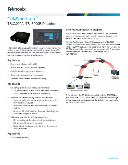
TekSmartLab ™TBX3000A, TSL3000B DatasheetTekSmartLab is the industry's first network-based instrument management solution for teaching labs, enabling a more efficient lab experience. With the TekSmartLab, instructors, students, and lab managers all benefit from improved connectivity, workflow, and automation.Key featuresEasy to setup with industrial reliabilityIntuitive instructor - course - exercise organizationCentralized monitoring and remote assistanceOnline editing and submission of test reports Automatic instrument asset information recordingKey benefitsLab managers can efficiently manage lab instruments:Setup configurations of large fleets of instruments with one clickCapture instrument asset information automaticallyInstructors can manage teaching work flow more efficiently:Instrument configuration can be saved and distributed to all theinstruments when requiredMonitor and control the lab instruments remotely to assist thestudentsDefine report templates and have them load automatically whenstudents are using smart devicesStudents can interact with their lessons seamlessly:Retrieve and save test results wirelessly via smart devicesEdit and submit test reports electronicallyDownload materials that are on the lab server (lab procedures,videos, and more)ApplicationsBasic teaching laboratoryTekSmartLab network diagramIn traditional teaching labs, connecting instruments to a network can be challenging, building an internal network through cables is tedious, and many lab instruments do not have a LAN port.Tektronix TekSmartLab is different: On each bench, the TBX3000Aconnects and controls instruments through USB cables, and communicates with the TSL3000B software on the lab server via the wireless network. The TBX3000A has a LAN port (standard), and can support a WI-FI connection when equipped with a compatible USB-WIFI dongle, such asTEK-USB-WIFI.On the lab server, the TSL3000B communicates with the TBX3000A on each bench. The TSL3000B gives instructors centralized control of large fleets of instruments and gives students the ability to retrieve test results,and edit test reports online.Campus level TekSmartLabWhen one lab manager must manage multiple labs, it can be a challenge to manage all of the instruments efficiently since the lab manager needs to spend time visiting each of the different labs. With campus level TekSmartLab, the lab manager can centrally control and monitor theinstruments in different labs remotely from his own office.Campus level TekSmartLab network diagramAs shown in the example above, TekSmartLab systems are setup in each of the labs and the lab servers are connected to a local area network, such as a campus network. TekSmartLab software is installed on the labmanager's computer, which is connected to the same local area network.Once the lab servers and the lab manager computer are connected to the local area network and can communicate properly, the lab manager can access any of the lab servers to remotely monitor and control the instruments in that lab.Easy to setup with industrial reliabilityTekSmartLab can be easily setup via WI-FI without laying LAN cables.Without any configuration, instruments are recognized automatically by the system when they are connected to the system.For the labs which have already equipped with Tektronix and Keithley instruments, instructors can smoothly update their labs to TekSmartLab as most of the Tektronix and Keithley teaching lab instruments are supported,even some instruments that have been phased out in the last five years (see Specifications ).Instead of controlling all the instruments by lab server directly, theTBX3000A on each bench controls the instruments connected to it. Using the TekSmartLab is an efficient and stable way to work. The TBX3000A,which is based on the Tektronix oscilloscope platform, works seamlessly with Tektronix and Keithley instruments, assuring the industrial reliability of the entire system.Course and exercise based applicationsTekSmartLab uses an instructor - course - exercise oriented hierarchy, an organization familiar to instructors at most universities: Instructors have different courses, and within each course there are different exercises. New exercises are easily created using the instructor name and course name,and easily selected with the same information.Applications, like saved configuration, exercise material sharing, and reporttemplates, for instance, are linked to specific exercises.Centralized configurationInstructors can setup the configurations of the instruments and distribute them to over 100 instruments with a single click. Instrument configuration changes can be made and delivered anytime; for example, the Autoset function can be disabled to encourage students to learn how to manuallyadjust an oscilloscope to display the correct waveform.DatasheetInstrument configuration can also be saved into a specific exercise andrecalled when the exercise is selected.When the TBS1000B-EDU series oscilloscopes are connected to the system, the courseware contents, as well as instrument firmware, can be updated remotely, a manual update for each instrument via USB thumb drives before.Centralized monitoring and remote assistanceWith TekSmartLab, the physical bench layout and lab layout is easily emulated: The number and type of the instruments on the bench can besetup, and the location of each bench within the lab can be customized.Instructors can easily monitor the status of all instruments during theexperiment: Green signifies that the instrument is working, gray signifies no connection, and red signifies an error. An instructor can check on or help aspecific bench by clicking the corresponding bench icon.Clicking a bench icon displays the readouts and key configuration settingsfor the instruments on that bench.TekSmartLab TBX3000A TSL3000BRetrieving and saving test reports onlineIn a traditional teaching lab, when students need to save test results they typically take snapshots of oscilloscopes and download those to a USB thumb drive or, more often, use a mobile device to take the picture. The result is that the quality of test results is not consistent and test results are difficult to archive for future access.TekSmartLab provides a more intelligent approach for editing andsubmitting test reports online: The TSL3000B server software creates a web page available in the local network for each bench. Each web page can be conveniently accessed by bench-specific IP address.With TSL3000B, instructors can change the IP address to QR (quick response) codes, and place it permanently as a printed sticker on eachbench.Students can login in to the web page using their mobile device to scan the QR code or by inputting the IP address in the web browser of their laptops.Once logged in, students can easily edit and submit test reports online.When students create a new test report, the report template, created byinstructor and saved on the server, is loaded automatically.When students edit their test reports, test results, like snapshots of theoscilloscope retrieved wirelessly, can be inserted at any time.The test report can be downloaded locally or archived on the lab server forfuture access.DatasheetSharing exercise material onlineTekSmartLab integrates FTP into the distribution of materials, allowing instructors to easily share any type of exercise materials, whether they arePowerPoint, Word, or even video, to students efficiently.Once instructors load exercise materials onto the lab server, students candownload them though the lab server web page onto their smart devices.Automatic instrument asset information recordingIn conventional teaching labs, the asset manager manually checks and records information such as instrument model numbers, serial numbers,and locations. Detailed information like the length of usage can only be estimated by experience or by keeping usage logs.The TekSmartLab solution automatically records and displays asset information, including time in use. Just one click archives the asset and usage information. TekSmartLab dramatically increases asset management accuracy compared to previous methods and makes managing lab assetsmuch more efficient.Sample TekSmartLab configurationThe following shows a sample setup of a TekSmartLab system with 15 benches and 60 instruments connected through WI-FI.1To use WI-FI on systems with more than 15 benches, it is recommended to setup the WI-FI network by wired router and access points instead of a WIFI router.TekSmartLab TBX3000A TSL3000BDatasheetSpecificationsAll specifications are guaranteed unless noted otherwise. All specifications apply to all models unless noted otherwise.TBX3000A characteristicsGeneral characteristicsMax instruments connected6, by USB cablesCompatible USB-WIFI dongle TEK-USB-WIFILAN Port 1LED 6 – Instrument status indicators1 – Wi-Fi connection status indicator1 – System status indicatorEnvironmental characteristicsTemperature Operating. 0 °C to 40 °CNon-operating. -20 °C to +60 °CHumidity Operating. (Low) 0 °C to 40 °C, 10% to 90% relative humidityNon-operating. (High) 40 °C to 60 °C, 5% to 60% relative humidity; (Low) 0 °C to 40 °C, 5% to 90% relative humidity.Altitude Operating. Up to 3,000 m (10,000 ft.)Non-operating. Up to 15,240 m (50,000 ft.)Regulatory complianceEMC compliance EN61326, Class A.Power consumption Maximum 15 WPhysical characteristicsMaximum benches supported100Maximum instruments supported600 (six instruments per bench)Bench layout emulation Select bench layout template (from 1 to 6 instruments), select instrument typeLaboratory layout emulation Add, Delete, Bench NumberLarge fleet configuration By exercise, by instrument typeTekSmartLab TBX3000A TSL3000BTSL3000B general characteristicsSupported instrumentsOscilloscopes Tektronix TBS1000B-EDU seriesTektronix TBS2000 seriesTektronix TDS2000C seriesTektronix DPO/MSO2000B series (oscilloscope function only)Tektronix MDO3000 series (oscilloscope function and spectrum analyzer function only)Arbitrary function generators Tektronix AFG1000 seriesTektronix AFG2021Tektronix AFG3000C seriesDigital multimeters Keithley DMM2110Keithley DMM2100Tektronix DMM4000 seriesPower supplies Keithley 2230G(J)-30-1Keithley 2220G(J)-30-1Keithley 2220(J)-30-1Keithley 2230(J)-30-1Keithley 2231A-30-3 (requires Option 2231A-001)Discontinued instruments Tektronix TDS1000B seriesTektronix TDS1000C-SC seriesTektronix TDS1000C-EDU seriesTektronix TBS1000Tektronix DPO/MSO2000Tektronix AFG3021BTektronix AFG3022BTektronix AFG3011Tektronix AFG3101Tektronix AFG3102Tektronix AFG3251Tektronix AFG3252General functions Check status, preset, record model number, S/N, time of use and locationOscilloscope functionsAnalog channel ON/OFFDigital channel ON/OFF (MSO2000 and MDO3000 with digital channel option only)Set/Check input coupling (AC, DC, Ground)Set/Check input attenuationSet/Check horizontal/vertical resolution and scale Set/Check trigger level (support Edge trigger only)Set/Check cursors (support time and amplitude mode only)Set/Check measurement (Frequency, Period, Rise time, Fall Time, Positive Pulse Width, Negative Pulse Width, Peak to Peak,Amplitude, Maximum, Minimum, High, Low, Positive Overshot, Negative Overshot, Mean, RMS)Check/Save snapshotWaveform update (analog channel only)Autoset Enable/Disable AutosetCourseware contents and firmware remote update (support for the TBS1000B-EDU series only)Spectrum Analyzer funtions (MDO3000 series only)Set/Check start/stop frequency, center frequency, span Set/Check reference levelSet/Check RBW mode, RBW value, window Waveform updateManual/Peak markers ON/OFF Spectrogram ON/OFFArbitrary Function Generator (AFG) functionsSet/Check carrier waveform (support Sine, Pulse, Ramp, Square, Noise, DC waveforms)Set/Check carrier frequency, amplitude, phase, pulse width (for Pulse only), symmetry (for Ramp only)Set/Check modulating type: AM, FM, PM, FSK, Sweep, Burst Set/Check output impedance, voltage limit Output ON/OFFDigital Multimeter functionsSet/Check measurement function: DCI, DCV, ACI, ACV, Ohm (2 wires, 4 wires), Frequency, Period, Temperature Set/Check Auto/Manual range, Integration Time, Auto Zero, Detector Bandwidth, Reference, Digital Filter Check measurement resultPower supply functionsSet/Check setting voltage/currentCheck output voltage/current (resolution 3 decimal digits)Output ON/OFFTest report online editing and submitting functionQR code generation Support Web browser access Support Test report template format docx Created test report format HTMLTest report edit functionsCreate a new report, edit text, insert oscilloscope snapshot, insert instrument setting, submit report, download reportDatasheetTSL3000B general characteristicsSystem requirementsOperating system Win 7 Professional (Enterprise or Ultimate), Win 8.1 Professional (Enterprise), Win 10 Professional (Enterprise)CPU Dual core 2.3 GHz or above RAM 4 GB DDR3 or above Hard disk 200 GB (minimum)Screen resolution 1366 x 768 or aboveWeb service IIS6.0 or above (supplied with system)DatabaseSQL Server 2014 Express (free download from the Microsoft website)WI-FI networking requirements (for labs with 15 benches)802.11n, 2.4 GHz, 300 Mbps data transfer rate Signal level >= -50 dBm Signal to noise >= 35 dBMax clients accessed>=31 (15 clients are TBX3000A, 15 clients are students' mobile devices, and one client for the lab server)TekSmartLab TBX3000A TSL3000BTSL3000B general characteristicsOrdering informationTekSmartLab ™TBX3000A TekSmartLab ™ hardwareTSL3000B-FLTekSmartLab ™ software, floating licenseHow to orderTekSmartLab ™ software is available for download at /downloads .In July 2017, the license policy and nomenclature was changed for TekSmartLab ™ software. The legacy system with TSL3000B will continue to be supported in the software,so there is no need to change your current licenses when upgrading to the latest version software.The new application license with TSL3000B-FL offers floating licenses (FL) that can be checked in and out of the Tektronix Asset Management System (Tek AMS) on the Tektronix website.TBX3000A power plug optionsA0North America A1Universal EURO A2United Kingdom A3AustraliaA4240v North AmericaA5Switzerland A6Japan A10China A11India A12BrazilA99No Power Cord or AC AdapterTBX3000A service optionsR5Repair Service 5 yearsTBX3000A warrantyWarranty3 yearsRecommended accessoriesTEK-USB-WIFIThis dongle is certified to comply with CE, FCC and IC regulations. Available in Australia, Canada, China, EU Region, New Zealand, and United States.Tektronix is registered to ISO 9001 and ISO 14001 by SRI Quality System Registrar.DatasheetTekSmartLab TBX3000A TSL3000B 11DatasheetASEAN / Australasia (65) 6356 3900 Austria 00800 2255 4835*Balkans, Israel, South Africa and other ISE Countries +41 52 675 3777 Belgium 00800 2255 4835*Brazil +55 (11) 3759 7627 Canada180****9200Central East Europe and the Baltics +41 52 675 3777 Central Europe & Greece +41 52 675 3777 Denmark +45 80 88 1401Finland +41 52 675 3777 France 00800 2255 4835*Germany 00800 2255 4835*Hong Kong 400 820 5835 India 000 800 650 1835 Italy 00800 2255 4835*Japan 81 (3) 6714 3086 Luxembourg +41 52 675 3777 Mexico, Central/South America & Caribbean 52 (55) 56 04 50 90Middle East, Asia, and North Africa +41 52 675 3777 The Netherlands 00800 2255 4835*Norway 800 16098People's Republic of China 400 820 5835 Poland +41 52 675 3777 Portugal 80 08 12370Republic of Korea +822 6917 5084, 822 6917 5080 Russia & CIS +7 (495) 6647564 South Africa +41 52 675 3777Spain 00800 2255 4835*Sweden 00800 2255 4835*Switzerland 00800 2255 4835*Taiwan 886 (2) 2656 6688 United Kingdom & Ireland 00800 2255 4835*USA180****9200* European toll-free number. If not accessible, call: +41 52 675 3777For Further Information. Tektronix maintains a comprehensive, constantly expanding collection of application notes, technical briefs and other resources to help engineers working on the cutting edge of technology. Please visit . Copyright © Tektronix, Inc. All rights reserved. Tektronix products are covered by U.S. and foreign patents, issued and pending. Information in this publication supersedes that in all previously published material. Specification andprice change privileges reserved. TEKTRONIX and TEK are registered trademarks of Tektronix, Inc. All other trade names referenced are the service marks, trademarks, or registered trademarks of their respective companies.20 Dec 2018 61W-60019-5 。
默纳克三代柜3000-B调试指导(含新国标)

本文主要是针对NICE3000-B系列的控制柜做的调试指导,希望能够给各位带来方便,欢迎收藏关注。
0、概述名词解释:①紧急电动运行F3-25设定运行速度:紧急电动运行是在机房控制柜将电梯打到紧急电动运行档,可以短接部份预设的安全回路开关,并能将电梯开动到平层位置,将人安全放出来。
主要作用:在电梯出现部份开关动作时,也能手动点动运行电梯,不用去手动盘车。
紧急电动运行(和检修一样,不过检修没有短接线路)②检修运行F3-11设定检修运行速度:轿顶打到检修档,通过手动点动运行电梯,实现井道部件的安装及门锁检查。
③其他速度说明F0-03:电梯的实际运行速度≤F0-04电梯额定速度,降低运行速度是只能设置F0-03电梯的运行速度。
F3-26:井道自学习速度,用于电梯井道自学习时的运行速度,紧急电动状态进入井道自学习指令,确认后转为正常状态,启动井道自学习④新国标:UCMP、门旁路及制动力检测见下文。
⑤E88测试状态:E88表示系统进入测试状态,并非故障代码。
⑥状态指示:上电显示0.0或者-0.0紧急和测试操作屏1、系统连接图2、主要回路①安全门锁回路NICE3000B系列电梯一体化控制柜的控制器设计了四个高压检测点(X25、X26、X27、X28),分别用做安全检测、门锁粘连检测、门锁检测和门锁粘连检测。
在接口板内部增加安全回路3个高压检测点指示灯,用于指示电梯控制柜安全回路、井道底坑安全回路和机房内安全回路的通断状态,用于现场方便的定位电梯安全回路故障;当出现以下几种情况时,安全回路断开。
a、柜内急停开关动作时;b、电梯系统中,安全部件电气开关断开时。
电梯在启动时,当且仅当四个高压点输入正常,即安全回路、门锁回路均正常时,电梯才可以正常运行。
②检修与紧急电动(轿顶检修通讯)参数名称参数设置F5-04X4功能选择118:门锁旁路常闭输入F5-09X9功能选择116:紧急电动常闭输入开通轿顶通讯检修F5-10X10功能选择09:紧急电动上行常开输入F5-11X11功能选择10:紧急电动下行常开输入注:X9对应点设为40时,关闭通讯检修功能,轿顶无法运行。
Keysight InfiniiVision 3000T X 系列示波器 用户指南说明书
Keysight InfiniiVision 3000T X 系列示波器用户指南声明© Keysight Technologies, Inc. 2005-2022根据美国和国际版权法,未经 Keysight Technologies, Inc. 事先同 意和书面允许,不得以任何形式或通过 任何方式(包括电子存储和检索或翻译 为其他国家或地区的语言)复制本手册 中的任何内容。
手册部件号75037-97089版本第八 版, 2022 年 6 月仅提供电子格式发布者:Keysight Technologies, Inc.1900 Garden of the Gods Road Colorado Springs, CO 80907 USA修订历史75037-97002, 2014 年 11 月75037-97015, 2015 年 8 月75037-97027, 2016 年 7 月75037-97040, 2017 年 11 月75037-97052, 2019 年 5 月75037-97064, 2020 年 10 月75037-97076, 2021 年 10 月75037-97089, 2022 年 6 月担保本文档中包含的材料" 按现状"提供,在将来版本中如有更改,恕不另行通知。
此外,在适用法律允 许的最大范围内,Keysight 不对本手册及其包含的任何信息提供任何明示或暗示的保证,包括但不仅限于对适销性和用于特定用途时的适用性的暗示担保。
对于因提供、使用或运用本文档或其包含的任何信息所导致的错误或者意外或必然损害,Keysight 概不负责。
如果Keysight 和用户之间已达成的单独书面协议包含涉及本文档内容的担保条款,但担保条款与这些条款有冲突,则应以单独协议中的担保条款为准。
技术许可对于本文档中描述的硬件和/或软件,仅在得到许可的情况下才会提供,并且只能根据许可进行使用或复制。
CYT1000B产品规格书
u IC(t ) u(t ) V (t )
2Usin(2ft ) V (t )
(8)
IC 的功耗是对上式进行积分计算,如下:
PIC ( 2 Usin(2ft ) V F ) * I F dt / T
T1
T2
(9)
5、 电源效率计算
PLED / (PLED PIC P固有损耗) %
联系人:赵蓉 15907550785 QQ:2355407129 E-mail:rzhao@ 地址:深圳市龙华新区梅龙路星河盛世 A3-2 栋 909-912 第 9 页 共 10 页
Vrext 600mV (mA) Rs Rs
联系人:赵蓉 15907550785 QQ:2355407129 E-mail:rzhao@ 地址:深圳市龙华新区梅龙路星河盛世 A3-2 栋 909-912 第 3 页 共 10 页
深圳市山墨电子有限公司
CYT1000B线性恒流LED芯片
CYT1000B线性恒流LED芯片
I LED I F * T / T
LED 电压的有效值如下:
(5)
V LED V F * T / T
LED 的功耗计算如下:
(6)
PLED V LED * I LED I F * V F * (T / T )
4、 IC 功耗计算
(7)
市电的电压和灯珠电压的差是 IC 的工作电压,其表达式如下:
CYT1000B 理论计算
VF/IF
T1
T2
1、 市电的波形函数是一个正弦曲线(如图 2) ,表达是如下:
u
2U sin(2ft )
(1)
其中:U:市电有效值,f:市电频率,φ:初始相位 式 1 的逆运算可以求出
WP-CAN3000B电梯控制器说明书
① 主控板(代号:WP-CAN3000B)。 ② 轿内主板(代号:WP-CAN-01C/D)。 ③ 轿内指令 I/O 板(代号:WP-CAN-02C/D),每八层配一块。 ④ 外呼指令与层楼显示板每一层外呼配一块,轿内层楼显示配一块,可以兼容的显示 板有 WP-CAN03A,03B,03C,03D,07A,07B
时仿真和跟踪的 32 位的微控制器,带有 256k 字节嵌入的高速 Flash 存储器。128 位 的存储器接口和独特的加速结构使 32 位代码能够在最大时钟速率(WP-CAN3000B 为 44M ) 下运行。 ② 采用 CANBus 局域网串行通讯技术,通讯速度高达 125Kbit/S,指令通讯延时<9ms, 控制实时性强、信号响应快。 ③ 无以伦比的通讯接口性能,3 路独立带有先进的验收滤波器的 CAN 通讯口, 2 路 RS232 口,极大的提高功能扩展能力。 ④ 采用大屏幕液晶显示器, 中文/英文 菜单式操作,方便简洁,分级密码进行参数设 置,安全可靠,还可进行故障查询、运行记录查询(运行时间、次数)等操作。 ⑤ 自带实时时钟、故障判断功能,能自动记录故障发生类型、时间,给电梯维护、故 障处理提供有力的手段。 ⑥ 系统采用模块化结构,内指令板直接处理轿内信号及完成门机控制,全串行通讯结 构,安装省时、省力。 ⑦ 可提供远程监控功能,可提供并联功能。 ⑧ 线路板采用 SMT(表面贴装技术)焊接工艺,线路板加工质量可靠,外型美观、小 巧。低功耗系统设计,主板功率<1W。 ⑨ WP-CAN3000B 微机控制系统通过德国 TUV 认证测试,具有独特的抗干扰设计,系 统抗干扰性能强,通讯电源采用多路的 DC/DC 模块隔离, 极大的提高通讯的抗干 扰性能,单独指令板发生故障时系统进行自动识别,不影响系统正常运行。线路板 进行过严格的 EMC(电磁兼容)检测,元器件进行过严格筛选,如输出继电器进行 过 300 万次寿命检测,从而能确保系统的可靠性。 ⑩ 高速计数输入口为高速电梯提供速度比较、监控功能,极大t Controller
Altium 3000-series Nano Board 产品概述说明书

Altium's 3000-series Nano BoardProduct Overview:Each of Altium's 3000-series NanoBoards is a242 x 176mm (9.5" x 6.9") six layer printedcircuit board (4 x signal, 2 x plane), powered byan external 5 Volt regulated supply. One of theplane layers is used predominantly as agrounding plane (GND, AGND, AUGND,SHIELD), but incorporates split regions toaccommodate 1.2V, 1.8V and 2.5V supplies.The other plane is used primarily for 5V and3.3V supplies. Both top and bottom of the boardare used for component placement.For each variant in the NanoBoard 3000 series, the layout of the motherboard and available resources are the same – all that differs are the physical devices used for the Host (NanoTalk) Controller and the target User FPGA.Kit Contents:The NanoBoard 3000 includes a 12-month subscription to an Altium Designer Soft Design license which is linked to the NanoBoard in the box. This license option provides functionality to quickly start designing FPGA-based embedded systems, including:▪FPGA design entry in C, OpenBus, Schematic, VHDL and Verilog▪VHDL simulation engine, integrated debugger and waveform viewer▪Support for a range of 32-bit soft processors for use in FPGA design▪ A rich set of royalty-free IP core libraries including peripherals and▪user-configurable custom logic▪Full software development tool chain with libraries and source code▪Programmable FPGA-based instruments for hardware debug and▪ deployment▪Support for importing third-party FPGA IP cores, developing and▪reusing IP librariesKey Features:∙NanoBoard 3000XN – with fixed Xilinx® Spartan™-3AN device (XC3S1400AN-4FGG676C) ∙Integrated color TFT LCD panel (240x320) with touch screen that facilitates dynamic application interaction∙High-quality stereo audio capabilities including: Line in/out/ headphones, audio CODEC with I2S-compatible interface, analogue mixer, audio power amplifier and high-quality speakers (located on a separate speaker board attachment)∙USB hub, providing connection of up to three USB 2.0 devices, with interfacing handled by an ISP1760 i-Speed USB Host Controller∙SVGA interface (24-bit, 80MHz)∙Variety of standard communications interfaces: RS-232, RS-485, PS/2, 10/100 Fast Ethernet, USB2.0, S/PDIF, MIDI∙Dual SD card readers – for use by user FPGA and Host Controller respectively∙IR receiver – supports data transmitted using a 38kHz carrier frequency∙Programmable clock (6 to 200MHz) and fixed clock (20MHz) – both available to user FPGA ∙4-channel 8-bit ADC, SPI-compatible – providing maximum sample rate of 200ksps∙4-channel 8-bit DAC, SPI-compatible – operating at clock rates of up to 40MHz∙4x isolated IM Relay channels – each channel providing a 5V nonlatching DPDT relay with one coil ∙4x PWM power drivers∙8-way general purpose DIP-Switch, 8 RGB LEDs, 5 PDA-style push button switches and a Test/Reset button – all wired directly to theuser FPGA∙User prototyping area∙Dual 18-way (20 pin) I/O expansion headers, with power supply selection links∙On-board memories accessible by user FPGA256KB x 32-bit common-bus SRAM (1MB), 16M x 32-bit common-bus SDRAM (64MB), 8M x 16-bit common-bus 3.0V Page Mode Flash memory (16MB), dual 256KB x16-bit independent SRAM 512KB each)∙Four 8Mbit SPI flash memory devices – one containing Primary boot image for Host Controller, one containing golden boot image for Host Controller, two for use by user FPGA (for boot/embedded purposes)∙SPI Real-Time Clock with 3V battery backup∙Accommodates a single plug-in peripheral board for additional system flexibility∙Board ID memory – 1-Wire® ID system uniquely identifies the motherboard and any attached Altium peripheral board∙Host (NanoTalk) Controller hosts the NanoBoard firmware. Responsibilities include managing JTAG communications (with Altium Designer/User FPGA/connected peripheral board), as well as access to common-bus SPI resources.∙5V DC power connector with power switch, plus testpoints for all major supplies on the board (and GND)∙High-speed PC interconnection through USB 2.0 allows for fast downloading and debuggingOrdering InformationProducts:Part Number Manufacturer Farnell P/N Newark P/N10R0248 12-400-NB3000XN-01 Altium 1714411Associated Products:Part Number Manufacturer Description Farnell P/N Newark P/N10R0257USB 1714426JTAGADAPTER AltiumSerial SPI Flash Memory 1099669 26M1754Flash Memory STMicroelectronics68K4632RS-232 1379769Transceiver MaximCAN Bus Maxim Transceiver NA 24R9638ADC-IC NA68K9410 ADC Maxim78C3271IC NADAC MaximDAC67K5237Sense NAAmplifier MaximCurrent3 176247622M4732SpartanFPGA XilinxFlash Memory Spansion Flash NA 42K8611Switch Maxim Switch Addressable 96B0597 *******Power Supply Maxim Power Supply IC NA 67K426397K6120 SDRAM MicronMemory 121628097K6120 SDRAM MicronMemory 1216280Similar Products:Part NumberManufac turerDescription Support DeviceFarnell P/NNewark P/N12-401-DB42 Altium XILINX SPARTAN-3ADSP DB42 DAUGHTER BOARD Spartan 3A171442110R025512-401-DB46 Altium BOARD,DAUGHTER, DB46, VIRTEX-4 SXVirtex-4 1714422 10R025612-400-NB2DSK01 (ALTERA)AltiumDESKTOPNANOBOARD WITH ALTERA CYCLONE II Cyclone II 133790810R024512-400-NB2DSK01 (LATTICE) AltiumDESKTOPNANOBOARD WITH LATTICE ECP Lattice ECPNA 10R0246 12-400-NB2DSK01 (XILINX)AltiumDESKTOPNANOBOARD WITH XILINX SPARTAN-3Spartan 3 NA10R024712-400-NB2DSK01-DB30 Altium NANOBOARD KIT NB2 SPARTAN-3 Spartan 31714409 25R5626 12-400-NB2DSK01-DB31 Altium NANOBOARD KITNB2, CYCLONE II Cyclone II1714407 25R5627 12-400-NB2DSK01-DB32 AltiumNANOBOARD KIT NB2, LATTICE ECP LatticeECP171441025R562812-401-DB40 Altium ALTERA CYCLONE IIIDB40 DAUGHTER BOARD Cyclone III1714419 10R025312-401-DB41 Altium XILINXSPARTAN-3AN DB41DAUGHTER BOARDSpartan 3AN1714420 10R0254Document List: Datasheets:Part Number DescriptionSize Xilinx’s Spartan Series Spartan 3 User guide Spartan 3 Datasheet 8.94MB 5.1MB DS2406Dual Addressable Switch Plus 1Kb Memory 240KBMT48LC16M16A2TGCommon-Bus SDRAM2.9MBS29GL256N11FFIV10 Common-Bus Flash memory 4.8MBMAX8860 Linear Regulator 168KB MAX1831 Voltage Regulator106KBApplication Notes:File Name SizeXAPP058 - Xilinx In-System Programming Using an Embedded Microcontroller641KBXAPP195 - Implementing Barrel Shifters Using Multipliers 52KBXAPP452 - Spartan-3 FPGA Family Advanced Configuration Architecture 574KBXAPP453 - The 3.3V Configuration of Spartan-3 FPGAs 215KBXAPP454 - DDR2 SDRAM Interface for Spartan-3 Generation FPGAs 328KB。
BladderScan BVI 3000产品说明书
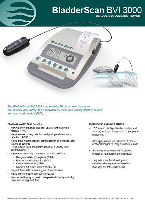
BladderScan BVI 3000BLADDER VOLUME INSTRUMENT• Noninvasively measures bladder volume and post-voidresidual (PVR)• Helps assess urinary retention and postoperative urinary retention (POUR)• Helps prevent unnecessary catheterization and unnecessary trauma to patients• Helps reduce rates of catheter-associated urinary tract infection (CAUTI)• Helps evaluate many common urological conditions:◦ Benign prostatic hyperplasia (BPH)◦ Bladder outlet obstruction (BOO)◦ Overactive bladder (OAB)◦ Lower urinary tract symptoms (LUTS)• Helps differentiate between types of incontinence • Helps monitor intermittent catheterization •costs and saving staff timeBladderScan BVI 3000 Features• LCD screen displays bladder position and volume; aiming icon assists in proper probe placement • 3D display shows the bladder in 2 cross-sectional images to verify an accurate scan • Easy-to-print exam results for patient records or reimbursement procedures • Helps document cost savings andcatheterizations-prevented based on user-determined statistical inputBladderScan, the BladderScan symbol, Scan Point, Verathon, the Verathon Torch symbol, and V MODE are trademarks of Verathon Inc. © 2007, 2011, 2012 Verathon Inc.The BladderScan ® BVI 3000 is a portable, 3D ultrasound instrumentthat quickly, accurately, and noninvasively measures urinary bladder volumeand post-void residual (PVR).Cart (optional)ConsoleBladderScan BVI 3000 TechnologyThe BladderScan BVI 3000 calculates bladder volume using patented V MODE ® ultrasound technology. A BVI 3000 exam is quick, easy, and comfortable for the patient. When you press planes inside the body producing a 3D image. Bladder volume measurements made with V MODE ultrasound are more accurate than those from conventional 2-dimensional ultrasound, as they are based on this more complex, 3D image.0900-1082-07-86Bladder Volume Range:Accuracy:Scan Time:Weight:Power:Display:Dimensions:0 to 999 mlinstructions, scanning a Verathon Inc. Tissue Equivalent Phantom: 0 to 699 ml ± 20%, ± 20 ml; 700 to 999 ml ± 25%, ± 25 ml Less than 5 seconds Less than 5 lb7.2v NiMH battery pack (2 supplied); six hours continuous use on one charge; battery low message Liquid CrystalWidth: 9.0” (23 cm), Length: 11.25” (32 cm), Height: 2.75” (7 cm)Temporal Average Power: 1 mW maximum Focal 20 dB Beam-Area: 1.4 cm 2Transducer Dimension: 13 mm diameter Working Frequency: 2 MHzPeak Instantaneous Intensity: 14 W/cm 2 maximum Pulse Repetition Frequency: 180 pulses/second Scan angle: 120 degreesMode: V MODE (multiple, aligned B-mode images)Temperature: +10° C to +40° CHumidity: 30% to 75%, non-condensing*SPTA = Spatial peak temporal average SPPA = Spatial peak pulse averageISO 13485:2003 standards. US 6,884,217 and other patents pending.• Compact console with easy-to-read LCD screen • Two NiMH rechargeable batteries • Battery charger• Onboard printer for patient records or reimbursement • Ultrasound gel•User’s Manual, Quick Reference Guide and Quick Reference Cards• Optional medical cart with locking wheel Batteries and chargerBladderScan BVI 3000 System IncludesUltrasound Parameters:Operating Conditions: BVI 3000DiagnosePreventManage and Treat• Avoid unnecessary catheterization and reduce rates of CAUTI • Reduce incontinent episodes• Measure post-void residual (PVR) and verify an empty bladder •• Assess postoperative urinary retention (POUR)• Identify blocked Foley catheters• Evaluate need to catheterize • Discontinue Foley catheter use• Establish voiding schedules and assist in bladder retraining BladderScan BVI 3000 HelpsVerathon Inc.20001 North Creek Parkway Bothell, WA 98011 / USA800 331 2313 (US and Canada Only)425 867 1348 / Fax 425 883 2896Verathon Medical (Europe) B.V.Willem Fenengastraat 131096 BL Amsterdam, The Netherlands +31 (0) 20 210 30 91Fax +31 (0) 20 210 30 92 | 。
WP-CAN3000B电梯控制器手册
韦伯电子电梯控制器使用手册W P-C A N-3000B电梯控制器Lift Controller用户手册User ManualH_Ver1.0如有更改,恕不通知Subject to change without notice无锡韦伯电子有限公司前言WP-CAN3000B微机控制系统适用于4m/S以下,全集选64层以内VVVF电梯控制系统。
该系统主要有以下一些功能特点:① WP-CAN3000B 采用单CPU-CPLD 结构, 32位ARM 芯片,它是基于一个支持实时仿真和跟踪的32 位的微控制器,带有256k 字节嵌入的高速Flash 存储器。
128 位的存储器接口和独特的加速结构使32 位代码能够在最大时钟速率(WP-CAN3000B为 44M ) 下运行。
② 采用CANBus局域网串行通讯技术,通讯速度高达125Kbit/S,指令通讯延时<9ms,控制实时性强、信号响应快。
③ 无以伦比的通讯接口性能,3路独立带有先进的验收滤波器的CAN 通讯口,2路RS232 口,极大的提高功能扩展能力。
④ 采用大屏幕液晶显示器,中文/英文菜单式操作,方便简洁,分级密码进行参数设置,安全可靠,还可进行故障查询、运行记录查询(运行时间、次数)等操作。
⑤ 自带实时时钟、故障判断功能,能自动记录故障发生类型、时间,给电梯维护、故障处理提供有力的手段。
⑥ 系统采用模块化结构,内指令板直接处理轿内信号及完成门机控制,全串行通讯结构,安装省时、省力。
⑦ 可提供远程监控功能,可提供并联、群控功能。
⑧ 线路板采用SMT(表面贴装技术)焊接工艺,线路板加工质量可靠,外型美观、小巧。
低功耗系统设计,主板功率<1W。
⑨ WP-CAN3000B微机控制系统通过德国TUV认证测试,具有独特的抗干扰设计,系统抗干扰性能强,通讯电源采用多路的DC/DC 模块隔离,极大的提高通讯的抗干扰性能,单独指令板发生故障时系统进行自动识别,不影响系统正常运行。
SDS3000B说明书

注意事项在使用SDS3000B系统前,请务必详细阅读供应商为您提供的相关资料!SDS3000B电源为DC24V,所有的输入端低电平有效。
继电器触点输出时,触点容量为3A,250VAC/3A,30VDC。
当交流负载电压大于36V,直流负载电压大于24V时,请务必在输出端口加以如下的处理:关于接地:进入机房的接地线必须接至控制柜的接地排。
b.对于机房中设备如五线制电源输入的地线、电动机外壳、控制柜外壳,编码器的外壳(若使用时)必须可靠接地,接地点为控制柜的接地排。
c.对于控制柜中设备如变频器、开关电源、变压器必须可靠接地,接地点为控制柜的接地排。
d.对于轿顶设备如门机、轿厢顶部整体必须可靠接地,接地点为控制柜的接地排。
e.对于厅外呼梯盒也应统一接地,接地点为控制柜的接地排。
f.编码器(若使用时)外壳已经接地,但编码器的屏蔽线和外壳相通,此时编码器的屏蔽线另一端(接变频器端)不接地。
g.为了抑制线路间的感应干扰,还应该将变频器的输出动力线和编码器(若使用时)的走线分别导入已经接地的金属管内。
且动力线与信号线距离至少30CM 以上。
前言本资料对SDS3000B系列电梯微机控制器及其辅件在电梯安装、使用、维护等方面进行了系统的阐述。
本手册可作为采用SDS3000B系列电梯微机控制器进行系统设计的参考资料,也可作为系统安装、调试、维护的使用资料;本资料目的,主要讲述了SDS3000B电梯控制系统的安装、调试过程中涉及到的技术问题;详述SDS3000B电梯控制系统的调试过程、调试方法以及故障排除;本资料主要针对广大电梯设计人员,电梯现场配线人员;同时还为电梯维护人员提供相应的技术资料。
本资料面对对象:a.用户b.电梯控制系统设计者c.现场配线调试者d.公司技术支持人员目录第一章.概述 --------------------------------------------- 5 第二章.外型尺寸及端口描述 ------------------------------- 6 第三章.慢车运行 ----------------------------------------- 18 第四章.快车运行 ----------------------------------------- 24 第五章.功能描述 ----------------------------------------- 28 第六章.参数一览表 --------------------------------------- 33 第七章.故障排除 ----------------------------------------- 46 第八章.部分变频器参数设置 ------------------------------- 50第一章 概述SDS3000B系列是电梯控制专用微机控制器,其集成电梯的所有功能,并提供双位七段码显示器,以提示电梯的运行状态和电梯调试时参数设置。
3000变频说明书
前言
尊敬的用户:
前言
非常感谢您选用西驰 CFC 系列高性能高集成通用型变频器。 我们相信做出明智选择的您将与信赖西安西驰的所有用户一起见证精彩的改变,享 受西安西驰带给您的优质产品和服务。 CFC 系列变频器是高性能、多功能、高集成的通用型变频器,它采用模块化的功能设 计理念,可专为行业需求提供解决方案,并根据客户的要求进行二次开发。
最佳的冷却效果。卧式安装时,可能需要加额外的通风 装置。 ◆ 环境温度要求在-10~40°C 的范围内,如温度超过 40°C, 请取下上面面盖,如超过 50°C 需外部强迫散热或者降额 使用。建议用户不要在如此高温的环境中使用本产品, 因为这样将会极大降低产品的使用寿命。 ◆ 环境湿度要求低于 90%,无水珠凝结。 ◆ 安装在振动小于 0.5G 的场所,以防坠落损坏。不允许产 品遭受突然的撞击。
图 1-1 产品型号说明 1.3 设备铭牌说明
在产品箱体的右侧板下方,贴有标示产品型号及额定值的铭牌,铭牌内 容如图 1-2 所示
图 1-2 产品铭牌 1
产品使用手册
1.4 产品各部位名称说明
面盖固定插入孔 功率板连接端口 主控板 注塑机专用 信号接口板 面盖固定孔
输入铜排 主回路入口
下面盖安装孔
第四章 参数功能介绍 4.1 监控参数……………………………………………………… 30
I
产品使用手册
目录
4.2 系统参数 ……………………………………………………… 30 4.3 参数功能详细说明 ……………………………………………… 40 第五章 故障处理和维护 5.1 故障代码及对策………………………………………………… 66 5.2 异常现象及对策 ……………………………………………… 67 5.3 检查与维护注意事项…………………………………………… 68 5.3.1 检查与维护 …………………………………………………… 68 5.3.2 日常检查项目 ………………………………………………… 69 5.3.3 定期检查项目 ………………………………………………… 69 5.3.4 产品易损件的更换 ………………………………………… 70 5.3.5 产品的存贮 ‥……………………………………………… 71 5.3.6 产品的保修 ………………………………………………… 72 第六章 选配件 6.1 制动组件 ………………………………………………………… 73 6.2 远程操作适配器及延长电缆 ‥………………………………… 73 6.3 RS485 接口通讯与通讯协议 ………………………………………… 74 附录 1 RS485 通讯协议 ‥…………………………………………… 75 附录 2 供水附件的应用 ……………………………………………… 82 附录 3 产品保修卡 …………………………………………………… 86
CX3000 Cond Resistivity TDS 传感器传输器 控制器操作手册说明书
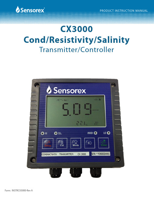
CX3000Cond/Resistivity/Salinity Transmitter/ControllerThank you for choosing the CX3000 Cond/Resistivity/TDS transmitter. This transmitter is a user-friendly microprocessor based transmitter for conductivity, resistivity and TDS measurement. As with all electronic instruments, it is essential to follow all directions for optimal performance. In particular, you must properly install, use and maintain the CX3000 to ensure that it will continue to operate within its specifications.• Follow all warnings, cautions and instructions supplied with the transmitter. Please contact Sensorex with any prod -uct questions or concerns.• Install the transmitter as specified in this manual, following all applicable local and national codes.• Do not attempt to repair your CX3000 transmitter or use any replacement parts from any other supplier.• If you find any errors in this manual, please report them to Sensorex.• Please complete the WARRANTY REGISTRATION located at the back of this manual and fax to SensorexCX3000 Cond/Resistivity/TDS Transmitter ESSENTIAL INSTRUCTIONSREAD THIS BEFORE USING YOUR CX3000 TRANSMITTER!About This DocumentThis manual contains instructions for the installation, operation and care of the CX3000 Cond/Resistivity/TDS transmitter. The following list provides notes concerning revisions of this document.Rev LevelDateNotesA10/20121st revision of manual.Table of Contents1. Specifications 12. Precautions for installation 33. Assembly and installation4installationTransmitter3.14. Overview of CX3000 Conductivity/Resistvity/Salinity transmitterpanelrear64.1ofIllustration4.2 General 74.3 Power 7function9terminalIllustration4.3of5. Configurationpanel 10frontIllustration5.1of10Description5.2FunctionKey5.3 LED indicators 12SecurityandDefault 13-14Codeicons5.4Display6. Operationmode 15 Measurement6.1mode 15 Set-up6.215mode6.3CalibrationReset 15 6.415reset6.4.1Masterreset 15 Calibration6.4.27. Settings7.1 Entry into set-up mode 167.2 Security code settings 167.3 Measurement Units 177.4 Temperature Settings 187.5 Temperature Compensation settings 197.6 Stand by Mode 207.7 Hi Alarm Relay (REL 1) 217.8 Lo point Alarm Relay (REL 2) 227.9 Wash time Relay 237.10 Analog output 1 (Cond/Res/Sal) 247.11 Analog output 2 (temperature) 257.12 Signal averaging of measurements 267.13 Power Supply Frequency Menu 277.14 Backlit LCD Menu 288. Calibration8.1 Calibration Flow Charts 298.1.1 Conductivity Calibration Flow Chart 298.1.2 Salinity Calibration Flow Chart 308.1.3 Resistivity Calibration Flow Chart 31Table of Contents8.2 Entry of calibration mode 328.2.1 Setting the CELL CONSTANT 328.2.2 Calibration using pre-set standards 339. Troubleshooting (Error Messages)9.1 Measurement Error Messages 349.2 Calibration Error Messages 34P roductRerturns Warranty10.and10.1 Warranty 3535 Items10.2ReturnofFigure 1-1Dimensional2SpecificationsFigure 3-1PanelMounting 4 Figure 3-2Pipe and Wall Mounting 5Figure 4-1 Rear6PanelFigure 4-2Power Schematic 7 Figure 4-3ESD Shield Removal 8Figure 5-1Front Panel View 10 Figure 5-2Display Icons 13 Figure 7-1Security Code Menu 16 Figure 7-2Measurement Unit Menu 17 Figure 7-3Temperature Measurement Menu 18 Figure 7-4Temperature Compensation Menu 19 Figure 7-5Standby Menu 20 Figure 7-6HI (Rel 1) Menu 21 Figure 7-7LO (Rel 2) Menu 22 Figure 7-8Wash Alarm Menu 23 Figure 7-9AnalogMenu 24Output1Figure 7-10Analog Output 2 Menu 25 Figure 7-11 Signal Averaging Menu 26 Figure 7-12 Power Supply Frequency Settings 27 Figure 7-13LCD Backlight Menu 28 Figure 8-1Conductivity Calibration Flow Chart 29 Figure 8-2Salinity Calibration Flow Chart 30 Figure 8-3Resistivity Calibration Flow Chart 31 Figure 8-4Setting Cell Constant 32 Figure 8-5Calibration using solution standards 33CX3000 SpecificationsMeasuring modes: Resistivity/Conductivity/Salinity/Temp.Ranges: Resistivity 0.00 -20.00MΩ/cmConductivity 0.000μS/cm-200.0 mS/cm in 6 ranges / Autoppt-70.0Salinity0.0-30.0to130.0°CTemp.Resolution: Resistivity 0.01 MΩ/cmμS/cmConductivity0.001pptSalinity0.10.1°CTemp.Accuracy: Resistivity ±1% (±1Digit)±1%(±1Digit)Conductivity(±1Digit)±1%Salinity(±1Digit)±0.2°CTemp.Measuring Unit 0.01, 0.1, 1.0, 10.00 cm-1 fixed, freely selectable 0.0050~19.99cm-1Temp Comp NTC30KΩ or PT1000 auto recognized or Manual adjustmentTemp Coeff Linear compensation from 0.00~20.00% Non-Linear compensation for natural water Ambient Temp. 0~50°CStorage Temp. -20~70°CDisplay: LCD display with illumination functionAnalog output 1: Isolated DC 0/4~20mA corresponding to main measurement, max. load 500ΩAnalog output 2 Isolated DC 0/4~20mA corresponding to Temp., max.load 500ΩSettings 1(HI) - Contact 240 V AC, 30V DC, 5.0A Max - programmable ON/OFF (SPST)2(LO) - Contact 240 V AC, 30V DC, 5.0A Max - programmable ON/OFF (SPST)WASH - Contact 240 V AC, 30V DC, 5.0A Max - programmable ON (0-9999 sec), OFF (0-999.9 hrs) Power Supply 100V~240VAC±10% 50/60Hz (software selectable)Mounting Installation Panel, or wallBox Dimensions: 144 mm × 144 mm × 115 mm (H×W×D)Panel Cut Out Dims: 138 mm × 138 mm (H×W)Weight :0.8 kgCertifications: IP 65 (NEMX 4X), CEpH / ORP Transmitter TX-3000(144mm)5.67”(144mm)5.67”(125mm)4.92”(98mm)3.74”Cord grip x3Panel mount ttings x4Front ViewSide ViewCX3000 Specifications - Dimensional SpecsWrong wiring will lead to breakdown or electrical shock of the instrument, please read this operation manual clearly before installation.Make sure to remove AC power from the controller before wiring input, output connections, and remove it before opening the transmitter housing.Install the transmitter in a well ventilated area and avoid direct sunlight.The material of signal cable should be special coaxial cable. Sensorex strongly recommend using our co-axial cable. Do not use normal wires instead.Avoid electrical surge when using power, especially when using three-phase power. Use ground wire cor-rectly.The internal realy contacts of the controller are designed for alarm and control function. Due to the safety and concern, please be sure to connect current with sufficient relay to load power, in order to ensure the operation safety of the instruments. (Please see chapter 4.3-Electrical connection diagram)3.1 Transmitter installation: This transmitter can be installed by panel mounting, wall mounting and pipe mounting.Panel Mounting : Cut a square hole of 5.4"(138mm) x 5.4"(138mm) on the panel, and then insert the trans -mitter directly into the panel. Attach the mounting bracket from the rear, so that it attaches to groove.Panel Cutout5.4"(138mm)5.4"(138m m )minimum distance between TX3000 panel cutouts = 1.7"(42mm)FIG 3-1Wall Mounting:Use 4 each M5 screws to attached to mounting holes shown below.Wall MountingFIG 3-24.1 Rear Panel:Figure 4.14.2 GeneralThe CX30000 requires 100-240V AC power (50/60 Hz selectable).Important Notes:1. Use wiring practices that conform to all national, state, and local electrical codes.2. DO NOT run sensor cables or instrument 4-20 mA output wiring in the same conduit that contains AC power wiring. AC power wiring should be run in a dedicated conduit to prevent electrical noise from coupling with the instrumentation signals.4.3 PowerFigure 4.24.3 Power (cont.)Power: Connect AC power to terminals 1 & 2. Power cord not included.Relays: Connect relays as shown. Relay 2 connects to terminals 5 & 6. Relay 1 connects to terminals 7 & 8. 240V AC, 30V DC, max 5.0A. Total current load should not exceed 5 amps at 240 VAC, 30V DC. Consider maximum in-rush current for devices connected to the CX3000 controller. If the current load can exceed 5 amps, please use and appropriate use a slave relay.4-20mA Outputs: Connect 10 & 11 to 4-20mA input (10 = -, 11 = +). This is the conductivity or resistivity or Salinity output. Connect 12 & 13 to 4-20mA input (12 = -, 13 = +). This is the temperature output. Sensor Connections:Remove ESD shield and install wires. Replace ESD shield after wires are connected .2 contact sensor - connect sensor wires to terminal 17 & 18. Place a jumper wire from 17 to 16 andfrom 18 to 19. Connect shield wire to terminal 20.4 contact sensor - connect sensor wires to terminal 16-19. Connect shield wire to terminal 20.Temperature sensor - connect temperature sensor wires to terminals 15 & 16.4-4 Description of terminal function:2-CONTACT Sensor WiringSHIELD (20) - Connected to the shield wire of the cable CELL 1 (19) - Jumper to #18CELL 2 (18) - Red wire of Sensorex cable (Cond)CELL 3 (17) - Black wire of Sensorex cable (Cond)CELL 4 (16) - Jumper to #17 + White wire Sensorex (TC)T/P - Green wire of Sensorex cable (TC)(11) 4~20mA(+)terminal : Master measurement current output terminal +, for external recorder or PLC control(12) 4~20mA(-)terminal : Master measurement current output terminal -, for external recorderor PLC control(13) 4~20mA(+)terminal: Temperature current output terminal +, for external recorder or PLC control (14) 4~20mA(-)terminal: Temperature current output terminal -, for external recorder or PLC control (7,8)REL 1 : External relay terminal High Point control(5,6)REL 2 : External relay terminal Low Point control External wash relay terminal (3,4)WASH : External wash relay terminal (1,2) 100~240AC: Power supply terminal4-CONTACT Sensor Wiring(20) - Connected to the shield wire of the cable(19) - CELL 1(18) - CELL 2(17) - CELL 3(16) - CELL 4 & TC (15) - TC5.1 Front PanelThe CX30000 keypad is designed for ease-of-use. See graphic below for keypad function.Figure 5-1In the parameter set-up mode, pressing this key allows you exit parameter set-up mode andback to Measurement mode.SetupIn the Calibration mode, pressing this key allows you exit Calibration mode and back to Mea -surement mode.5.2 Function Keys:In the parameter set-up mode and Calibration mode, pressing this key to increase the value or to scroll to other function.In the parameter set-up mode and Calibration mode, pressing this key to decrease the value or to scroll to other function.ModeKey for confirmation; pressing this key is essential when modifying data value or selecting the parameter setting items in the window.EnterIn the Measurement mode, pressing these two keys simultaneously allows you enter Calibration mode.ModeIn the Measurement mode, pressing these two keys simultaneously allows you to enter parameter set-up mode.ModeSetupIn the Measurement mode, press the "SETUP" and "MODE" keyssimultaneously for five seconds, and then press ENTER until you see a clock signal appearing on the display then stop pressing all keys to restore factory default settings.ModeSetup+EnterRestore factory default calibration’s settings. In the Measurement mode, press the "CAL " and "MODE" keys simultaneously for five seconds, and then press "ENTER" until you see a clock signal ap-pearing on the display; then stop pressing all keys to restore factory default settings.ModeEnter5.2 Function Keys:++5.3 LED indicators:HI: High set point indicator light; when the high set point is reached, the REL1 indicator will light. B.L.: Light sensor; in the automatic display backlit mode, the lamp will light or go out depending onenvironmental brightness.WASH: Washing device indicator light; when the washing device is started up, the indicator will light. LO: Low set point indicator light; when the low set point is reached, the REL2 indicator will light.5-4 Display Icons:Set-up mode:In the measurement mode, pressing the SETUP and MODE keys simultaneously allows you enter the parameter set-up mode. You can return to the measure -ment mode at any time by pressing the "SETUP" key .ModeSetupSecurity Code Settings:In the set-up mode, you can set up the code by following the steps below The original code is 1111. You can change the code to any 4-digit code you desire by following the same procedure as you used to enter the "1111" code.+6.1 Measurement mode:After all electrical connections are finished and tested, connect the transmitter to the power supply and turn it on. The transmitter will automatically enter measurement mode with the factory default settings or the last settings from user.6.2 Set-up mode:PRESS "SET UP" AND "MODE" SIMULTANEOUSLYPlease refer to the set-up instructions in Chapter 7, and press "SETUP" key to return to measurement mode.6.3 Calibration mode:PRESS "CAL" AND "MODE" SIMULTANEOUSLYPlease refer to the calibration instruction in Chapter 8, and press "CAL" key to return to measurement mode.6.4 Reset:6.4.1 Master reset:In the Measurement mode, press the "SETUP" and "MODE" keys simultaneously for five seconds, and then press the "ENTER" key until you see a clock signal appearing on the display. Release all keys and then factory default settings will be restored.Factory defaults:Measurement mode: Cond TemperatureTemperature compensation: NTCHigh point alarm: AUTO, SP1= 100.0 mSpH, db1= 0.10 mS/cmLow point alarm: AUTO, SP2 =00.10 uS/cm, db2= 00.10 uS/cmWash time: ON = 0 sec, OFF0.0 hrs, db = 0 secCond current output: 4~20 mA, 0.000uS/cm~199.9mS/cmTP current output: 4~20 mA, 000.0~100.0˚CBacklit Display: AUTO, b.L =0, SEnS=0Code set-up: OFF6.4.2 Calibration reset:In the Measurement mode, press the "CAL" and "MODE" keys simultaneously for five seconds, and then press the "ENTER" key until you see a clock signal appearing on the display. Release all keys and then factory default calibration settings will be restored.Factory defaults:Cell Constant: 1.0000Standard Solution: 1413uS/cmCalibration mode: Single-Point Calibration7.1 Set-up modeIn the measurement mode, pressing the "SETUP" and "MODE" keyssimultaneously allows you enter the parameter set-up mode. You can return to the measurement mode at any time by pressing the key "SETUP" key.SetupMode+7.2 SecurityIn the set-up mode, you can set up the code by pressing the key "MODE" , and confirm by pressing the "ENTER" key . The original code is 1111.EnterModeGO TO "MEASUREMENT7.3 Measurement Unit ModeIn the measurement unit mode, you can choose units for conductivity (Cond), resisitivity (RES) or salinity (SALT).EnterPress "ENTER" to enter measurement setup mode.ModePress "MODE" or "RIGHT ARROW" to select measurement mode.CONDUCTIVITY TDSRESISTIVITY SALINITYEnte r Ente r ** Press Mode button until desired range is on screen then press "ENTER".Auto range 2.000μS/cm 20.00μS/cm 200.0μS/cm 2000μS/cm 20.00mS/cm 200.0mS/cmEnte rEnte r Ente rEnte r** Press Mode button until desired range is on screen then press "ENTER".2000ppm 20.00ppt 200.0pptGO TO "TEMPERATURE SETUP ,SECTION 7.4Temperature(Celsius)Mode ORModeORModeTo enter correct temperature Compare with standard temp. meter7.4 Temperature measurement modeIn the Temperature measurement unit mode, you can choose the type of temperature sensor (NTC 30K) or PTC (1000 Ω RTD)7.5 Temperature Compensation ModeIn the temperature compensation mode, you can choose linear compensation range from 0.00% to 20.00% or non-linear for resistivity compensation.Non-Linear temp. compensationEnterModeTo choose temp comp methodPress confirm method To set temp compcoefficient.EnterGO TO "HI ALARM SETPOINT MODE"SECTION 7.67.5 Standby ModeIn the standby mode, you can choose Auto or ON for standby. Auto will set the return to MEASUREMENT mode to 3 minutes if no keys are touched. Choosing ON for standby requires you to press "SETUP" key to return to MEASUREMENT mode.EnterModeauto return or manually returnSETUPand return to theMEASUREMENTFIG 7-57.7 HI POINT SETTINGSet Hi (REL1) setpoint threshold(TH) and dead band value (DB). The range of threshold and deadband are: Resistivity:0.00MΩ~19.99MΩ Deadband:0.00MΩ~19.99MΩConductivity: 0.000μs~199.9mS Deadband: 00.00μs ~199.9 mS Salinity: 0.0ppt~70.0ppt Deadband: 0.0ppt~7.0pptEnterto enter the Hi point relay.Enterto exit Relay 17.8 LO POINT SETTINGSet Lo (REL2) setpoint threshold(TH) and dead band value (DB). The range of threshold and deadband are:Resistivity: 0.00MΩ~19.99MΩ Deadband: 0.00MΩ~2.00MΩConductivity: 0.000μs~199.9mS Deadband: 00.00μs ~199.9 mS Salinity: 0.0ppt~70.0ppt Deadband: 0.0ppt~7.0pptTo activate relay 2 or not.EnterModeand the units (μS/cm or mS/cm) also can be set.Enter7.9 WASH Alarm -Set the automatic starting time and turnoff time of the washing function. If any value is set to be 0, the transmitter will automatically stop this function.to activate the auto clean device to input clean device OFF duration.Modeto activate the auto clean device ModeOROROR7.10 Analog Output 1 (Conductivity/Resistivity/Salinity)This mode allows you to set the analog output as 4-20mA or 0-20mA for Conductivity/Resistivity/Salinity.ORto select current range (4-20mA or 0-20mA)Press "MODE" or "RIGHT ARROW"lower limit of Conductiv-ity value relative to the 4.0mA signal. If you set ModeGO TO ANALOG OUTPUT 2(TEMPERATURE)SECTION 7.11EnterEnterFIG 7-97.11 Analog Output 2 (Temperature)This mode allows you to set the analog output as 4-20mA or 0-20mA for temperature (deg C only).ORto select current range(4-20mA or 0-20mA)ORORModeof temperature value forthe 20mA signalORModeto select output testingEnterGO TO SIGNAL AVERAGING TIME7.12 Signal AveragingThis mode allows you to set the signal averaging time (0-60 seconds) to increase stability of displayed signal ArrayFIG 7-117.13 Power Supply Frequency ModeThis mode allows you to set the power supply frequency (U.S. 60HZ, Others 50Hz)ORModeEnterFIG 7-127.14 Backlit LCD ModeThis mode allows you to set the Backlit LCD to AUTO, On or OFF. In the AUTO mode it allows for setting of the LCD brightness and light sensor sensitivity.ORModeORGO TO SECURITY SETTINGSSECTION 7.28.1 Calibration Flow Charts8.11 Calibration Flow Chart for ConductivityEnter"ENTER"8.1 Calibration Flow Charts8.12 Calibration Flow Chart for Salinity1.08.1 Calibration Flow Charts8.13 Calibration Flow Chart for ResistivityIn the Measurement mode, pressing these two keys simultaneously allows you enter Calibration mode.Mode+8.2 Entry of Calibration Mode8.2.1 Setting the CELL CONSTANTIn the Measurement mode, pressing these two keys simultaneously allows you enter Calibration mode.Mode+or press "CAL " key to return to measuring mode at any time8.2.2 Standard Solution CalibrationMode OREnterThese symbols will flash"ENTER" for confirmation.9.1 Measurement ErrorsMessageReasonActionIn resistivity measuring mode when the value is over the measuring range, the following figure will be appear (Measuring range:00.00-19.99MΩ)Please check the sensor’s cable to see if it is broken. If it is ok, please check if the solution’s resisitivity is over range.In conductivity measuring mode whenthe value is over measuring range, the follow-ing figure will be appear:(Measuring range:00.00us-199.9msPlease check the sensor’s cable to see if it is shorted electrically. If it is OK, please check if the solution’s conductivity is over range.In salinity measuring mode when the value is over the measuring range, the follow figure will be appear:(Measuring range:0.0ppt~70.0ppt)Please check the sensor’s cable to see if it is broken. If it is OK, please check if the solu-tion’s salinity is over range.When temperature value is out of the display range, then the following figure will be ap-pear:(Measuring range:-30°C -130°C)Please check the sensor’s temp cable to see if it is broken. If it is still normal, please check if the solution’s temperature is over range.9.2 Calibration Errors10.1 WarrantyThe CX3000 Conductivity/Resistivity/Salinity transmitter/controller is supplied with a one-year warranty for material and workmanship from date marked on the product. No warranty, either expressed or implied, as to the useful life of the product is given. There are no implied warranties of merchantability or fitness for a particular purpose given in connection with the sale of any goods. In no event shall the seller be liable for consequential, incidental or special damages. The buyer’s sole and exclusive remedy and the limit of the seller’s liability for any loss whatsoever shall not exceed the purchase price paid by the purchaser for the product to which claim is made.10.2 Return of ItemsIf repair is necessary and is not the result of misuse, contact Sensorex for a Return Material Authorization Number (RMA#). No product returns will be accepted without prior authorization. You will be asked for the serial number of the transmitter/controller and a description of the failure. Customers are responsible for incoming freight charges on returned products. Sensorex will pay all outgoing freight charges on warranted returns. If, after evaluation, the product is deemed damaged due to misuse, you will be contacted regarding repair charges.Page 36 of 36Warranty Terms and Conditions********************************************************************************************* of purchase.2. The Warranty shall become void if any unauthorized repair, tampering or alteration is done on to the product.3. Do not remove or alter the serial number on the product. This will again void the warranty.4. The owner of the product must present a copy of this warranty card to request RGA service.5. The Warranty does not cover: a) Accessories, consumable items, wear and tear parts, corrosion, rusting or stains b) Incoming shipping cost when sending product in for repair c) Use of wrong electrical supply/voltage d) Dropping or other impact e) Use not in accordance with product manual 6. SENSOREX warrants all products to be free of defects in materials and workmanship for one year from date marked on the product or based on the serial number. However, SENSOREX offers no warranty, either expressed or implied, as to the useful life of these products. There are no implied warranties of merchantability of fitness for a particular purpose given in connection with the sale of any goods. In no event shall SENSOREX be liable for con sequential, incidental or special damages. All responsibilities for items not provided in this box (software, monitors, electrodes or power supplies) are not the responsibilty of Sensorex. The buyer’s sole and exclusive remedy and the limit of SENSOREX’s liability for any loss whatsoever shall not exceed the purchase price paid by 11751 Markon Drive Garden Grove, CA. 92841 USA tel: 714-895-4344 fax: A HALMA COM PA NY。
CY-3000无线遥控设备分析仪使用说明书_V1.0_
中文版无线遥控设备检测仪 CY-3பைடு நூலகம்00 使用说明书
片的所有参数,这样就相当于可以调整机器成为所支持芯片万能遥控器了,并 且可以将上面所编辑的数据保存在相应的组号,随时可以调出来使用。
12.增加了可以锁定/解锁已收录的数据的功能,使得用户有更得心应手的 应用。
13.保留了在翻查状态简单编辑按键数据的功能,可以实现按键位的三态切 换(即:0、1、F),且又增加了可以模拟遥控器实际应用的点动发射、长按发 射的工作方式(但这种方式,只可以实现按键位的二态切换,即:0、1、), 从而使得用户有更得心应手的应用。
中文版无线遥控设备检测仪 CY-3000 使用说明书
CY-3000 中文版
无线遥控设备检测仪使用说明书
2014-04-05 Ver 1.0
第 1 页 共 22 页
中文版无线遥控设备检测仪 CY-3000 使用说明书
目录: 1、购买本产品前必读.............................................3 2、产品简介.....................................................3 3、产品特点.....................................................4 4、菜单目录的操作方法及其功能说明...............................6
H.按"退出"键退回到上一级菜单,直到退回到接收状态。
I.如果想锁定/解锁当前翻查到的组号的数据,可 以在操作到上面的第 B 项后,按一次“上”键,表示 锁定当前的组号的数据,同时在屏的上部显示“L”, 表示已上锁,再按一次“下”键,表示解锁当前的组 号的数据,同时在屏的上部显示的“L”消失,表示已
四川新先达测控技术 能量色散 X 荧光分析仪 CIT-3000SYB 说明书
CIT-3000SYB 川制00000175号能量色散X荧光分析仪使用手册使用设备时请严格参考使用手册正确操作四川新先达测控技术有限公司国家核技术工业应用工程技术研究中心目录仪器开机必读 (1)第一章概述 (2)1.1 公司背景介绍 (2)1.2主要检测方法 (3)1.3 法定计量单位的名称、符号 (3)第二章工作原理和仪器参数 (3)2.1 X荧光分析仪基本理论及工作原理 (3)2.2 能量色散X荧光分析仪技术参数 (4)第三章设备安装 (5)3.1 仪器结构图 (5)3.2 装机操作流程图: (9)3.3 安装流程说明 (9)3.4 注意事项 (10)第四章通讯连接 (10)第五章软件安装和参数设置 (11)5.1 软件安装 (11)5.2 设置MCA主板参数 (11)5.3 设置控制板参数 (12)5.4 设置口令 (13)5.5 设置分析测量窗口 (13)5.6 设置本底测量窗口 (14)5.7 设置能量刻度峰 (15)5.8 设置寻峰刻度峰 (15)5.9 设置标定公式 (15)5.10 设置测量公式 (15)5.11 设置分析参数 (16)第六章数据库的建立及维护 (17)6.1 标准样品的测量及建立数据库 (18)6.2 标准数据库的的维护 (19)第七章测试样品操作流程 (20)7.1 样品制备 (20)7.2 校准测量 (21)7.3 分析样品 (21)7.4 已保存谱数据的重新计算 (22)7.5 标准方法分析 (22)7.6 查看测量结果 (22)7.7 数据结果打印 (23)7.8 准直器切换 (23)第八章常见故障及排除方法 (24)地 址:成都市成华区龙潭寺隆锦广场4楼Page 1仪器开机必读未经我公司培训或培训后未取得我公司颁发的合格上岗证书的人员禁止对我公司仪器进行任何测试,不合格操作人员使用仪器导致仪器任何部件的损坏不属我公司质保范围之内,务必安排有合格上岗证书的人员操作仪器,并且严格按照我公司提供的仪器使用说明书及操作规范流程正确使用仪器。
聚泉鑫led无频闪3段调光恒流驱动芯片CYT8000B规格书_V1.0
CYT8000B规格书产品说明CYT8000B是一款可3段调节亮度/色温的LED恒流驱动芯片,可以做完全无频闪方案。
适用于200Vac~240Vac或90Vac~130Vac输入电压,恒流精度小于±3%。
当CYT8000B在3段调节亮度应用中,可根据开启关闭电源开关,依次自动改变输出电流的大小,从而改变LED灯的亮度,调节比例可以通过外接CS电阻进行调整。
当CYT8000B在3段调节色温应用中,可根据开启关闭电源开关,依次改变两路输出端口开关状态,实现两路不同颜色LED灯的交替亮灭以实现调节色温的目的,调节外接REXT电阻可对输出功率进行调节。
CYT8000B整体设计结构简单,具有各种保护功能,无需变压器和高压电解电容,该高压LED驱动芯片只需极少的外围元器件,并且可以实现全部SMT加工,可实现全自动化作业。
特性无需变压器和电解电容输入电压220Vac、110Vac集成高压启动供电可实现3段调节亮度,调节比例可外部设置调光比例:100%--50%--X%或X%--50%--100%0.5秒~3秒内实现开关切换,支持快速开关切换 片间电流偏差<±3%功率因数>0.9THD:<20%具有温度自动调节功能 芯片应用系统无EMI问题封装形式ESOP8应用T5/T8系列LED日光灯管LED球泡灯LED桶灯LED吸顶灯引脚图典型示意电路图3段调光应用示意图3段调色温应用示意图引脚定义引脚名称引脚序号说明VCC1VCC电源端口GND2芯片地CS13输出电流值设置端口1 CS24输出电流值设置端口2 OUT25恒流输出端口2OUT16恒流输出端口2VIN7供电端口VDD8VDD电源端口极限参数特性参数符号范围OUT端口电压V-0.5~500VOUT-0.5~500V VIN端口电压VIN-0.5~+8V CS端口电压VCSVDD端口电压V-0.5~+8VDD-0.5~+8V VCC端口电压VCC工作温度TOPT-40~125℃存储温度TSTG-50~125℃HBM人体放电模式VESD>2000V电气特性参数符号条件最小值典型值最大值单位输出电流IOUT1~2~--60mA静态电流IDDVOUT=10V CS悬空-0.160.25mACS端口电压VCS1~2VIN=20V VOUT1~2=10V-0.6/0.3-VOUT端口工作电压VOUT1~2VOUT=30mA1--VIOUT片间误差DIOUTIOUT=20mA-±4-%电流负温度补偿起始点TSC~-110-℃热阻参数符号说明ESOP8单位RTHJA热阻(1)89.2℃/W (1)注:芯片要焊接在有200mm2铜箔散热的PCB板,铜箔厚度35um。
利普 Owon TAO3000 四通道系列数字存储示波器 用户手册说明书
TAO四通道系列数字存储示波器用户手册官方微信,一扫即得如需资料下载,请登录:/download2023.06版本V1.0.2©福建利利普光电科技有限公司版权所有,保留所有权利。
产品受专利权的保护,包括已取得的和正在申请的专利。
本文中的信息将取代所有以前出版资料中的信息。
本手册信息在印刷时是正确的。
然而,福建利利普光电科技有限公司将继续改进产品并且保留在任何时候不经通知的情况下变动规格的权利。
是福建利利普光电科技有限公司的注册商标。
福建利利普光电科技有限公司福建漳州市蓝田工业开发区鹤鸣路(原横三路)19号利利普光电科技楼Tel: 4006-909-365 Fax:************Web: E-mail:*************.cn保修概要本公司保证,本产品从本公司最初购买之日起3年(配件1年)期间,不会出现材料和工艺缺陷。
配件如探头、适配器等保修期1年。
本有限保修仅适于原购买者且不得转让第三方。
如果产品在保修期内确有缺陷,则本公司将按照完整的保修声明所述,提供维修或更换服务。
如果在适用的保修期内证明产品有缺陷,本公司可自行决定是修复有缺陷的产品且不收部件和人工费用,还是用同等产品(由本公司决定)更换有缺陷的产品。
本公司作保修用途的部件、模块和更换产品可能是全新的,或者经维修具有相当于新产品的性能。
所有更换的部件、模块和产品将成为本公司的财产。
为获得本保证承诺的服务,客户必须在适用的保修期内向本公司通报缺陷,并为服务的履行做适当安排。
客户应负责将有缺陷的产品装箱并运送到本公司指定的维修中心,同时提供原购买者的购买证明副本。
本保证不适用于由于意外、机器部件的正常磨损、在产品规定的范围之外使用、使用不当或者维护保养不当或不足而造成的任何缺陷、故障或损坏。
本公司根据本保证的规定无义务提供以下服务:a) 维修由非本公司服务代表人员对产品进行安装、维修或维护所导致的损坏;b) 维修由于使用不当或与不兼容的设备连接造成的损坏;c) 维修由于使用非本公司提供的电源而造成的任何损坏或故障;d) 维修已改动或者与其他产品集成的产品(如果这种改动或集成会增加产品维修的时间或难度)。
可视诱鱼探鱼一体系统的制作流程
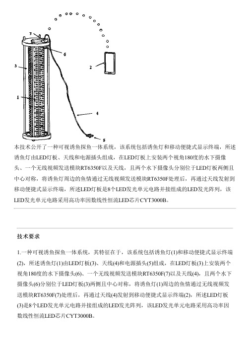
本技术公开了一种可视诱鱼探鱼一体系统,该系统包括诱鱼灯和移动便捷式显示终端,所述诱鱼灯由LED灯板、天线和电源插头组成,在LED灯板上安装两个视角180度的水下摄像头、一个无线视频发送模块RT6350F以及天线,且两个水下摄像头分别位于LED灯板两侧且中心对称,将诱鱼灯周边的鱼情通过无线视频发送模块RT6350F处理后,再通过天线发射到移动便捷式显示终端,所述LED灯板是8个LED发光单元电路并接组成的LED发光阵列,该LED发光单元电路采用高功率因数线性恒流LED芯片CYT3000B。
技术要求1.一种可视诱鱼探鱼一体系统,其特征在于,该系统包括诱鱼灯(1)和移动便捷式显示终端(2),所述诱鱼灯(1)由LED灯板(3)、天线(4)和电源插头(5)组成,在LED灯板(3)上安装两个视角180度的水下摄像头(6)、一个无线视频发送模块RT6350F(7)以及天线(4),且两个水下摄像头(6)分别位于LED灯板(3)两侧且中心对称,将诱鱼灯(1)周边的鱼情通过无线视频发送模块RT6350F(7)处理后,再通过天线(4)发射到移动便捷式显示终端(2),所述LED灯板(3)是8个LED发光单元电路并接组成的LED发光阵列,该LED发光单元电路采用高功率因数线性恒流LED芯片CYT3000B。
2.根据权利要求1所述的一种可视诱鱼探鱼一体系统,其特征在于:所述诱鱼灯(1)采用18片LED灯板(3)通过并联接法组成发光单元。
3.根据权利要求1所述的一种可视诱鱼探鱼一体系统,其特征在于:所述高功率因数线性恒流LED芯片CYT3000B的D1、D2、D3、D4为恒流输出端;RCS为输出电流值设置电阻;RD为功率自动调节设置电阻;RTH为温度自动调节设置电阻,在系统上电后,D1通过内部的高压MOS给芯片供电,当D1的电压超过10V之后芯片开始工作,CYT3000B根据输入电压变化而分段点亮不同的LED串数。
4.根据权利要求1所述的一种可视诱鱼探鱼一体系统,其特征在于:所述移动便捷式显示终端(2)为智能手机或平板电脑。
MCB-S3000(CNA)
SMCB-3000Ci 综合说明书(主控板)1章. MCB-3000SCi (主控板) 1. MCB-3000SCi Board 构成图2. Connector 说明1) CN1 (电源供应部)2) CN23) CN34) CN45) CN56) CN67) CN78) CN109) CN111)CN134)J15)CFO16)CFO37)CFO58)CFH19)CFH3(注)输出因素是MOSFET 继电器, 最大接点用量是100mA.19) J4 : 为组程序DSP集成电路片的Tool连接器.20)J3,J5,J6 : 为组程序CPLD集成电路片的Tool连接器.21)TB1 : PM马达编码器连接部22) TB2 (编码器连接部)1.Jumper Pin 说明1)JP1 : 未使用. 出厂时OPEN状态.2)JP2 : 只是DSP程序短路, 出厂时OPEN状态.3)JP3 & JP4 (选择编码器输入方法)4. DIP 开关说明1) D i p SW12) Dip SW2(注)2. ATT运行模式2 (ATT2) –使用ATT,AUP,ADOWN,ASTART,APASS,ACUT开关.5. LED 说明1)LD1: 变频器电容Charge LED,点灯的时侯,电场部分流高电压,请注意。
2)LD2: 数码电源状态表示LED,电源供应中点灯。
3)CTX: 在CRT通讯中,正在送信的时侯闪烁,没有送信资料的时候不亮.4)CRX: 在CRT通讯中,正在收信的时侯闪烁,没有收信资料或通讯错误的时候不亮.6. Test Pin 说明1)GND: 数码电源5V接地.2)CGND: IND, OPB通信电源接地.4章. OPB-100 Board (轿顶通讯板) 1. OPB-100 Board 构成图2. Connector 说明1) J11 (门机强制停止开关)2) J12 (消防运行开关输入)3) J13 (负载感应开关输入)4) J14 (SAFETY 开关输入)5) J15 (红外线光幕开关输入)6) J16 (继电器输出)(注) MOSFET 继电器输出, 最大接点用量是100mA.7) J17 (电源及通讯)8) J18 (控制输出)9) J19 (风扇及照明电源)10) J20 (风扇输出)11) J21 (照明输出)12) J22 (风扇及照明开关)13) J23 (继电器输出)14) J24 (DC24V 输出)16) J27 (输入)17) J28, J29 (OPB-2000SPA 连接)(注) J28和J29是一样的功能,与连接方向无关.18) J30, J31 (输入)(注) J30和J31是一样的功能,与连接方向无关.3. DIP 开关说明1) Dip SW1(注) 在17层以上的现场,如果有残障人功能的话,需要2张 OPB-100。
- 1、下载文档前请自行甄别文档内容的完整性,平台不提供额外的编辑、内容补充、找答案等附加服务。
- 2、"仅部分预览"的文档,不可在线预览部分如存在完整性等问题,可反馈申请退款(可完整预览的文档不适用该条件!)。
- 3、如文档侵犯您的权益,请联系客服反馈,我们会尽快为您处理(人工客服工作时间:9:00-18:30)。
扩展方案
图 3.CYT3000B 并联使用方案
宁波勤创节能科技有限公司
QQ :247859997 15967867939 苏先生
参考设计-应用电路图
宁波勤创节能科技有限公司
QQ :247859997 15967867939 苏先生
参考设计-7W BOM
元件位号 F1 VD1 DB1 R1 R2 R3 R4 IC LED 元件名称 保险丝 压敏电阻 整流桥 贴片电阻 贴片电阻 贴片电阻 贴片电阻 CYT3000B 18V 灯珠 规格型号 1A250V 贴片保险丝(可选) 7D471 插件压敏电阻(可选) MB10F 贴片整流桥 1206 18R 1% 1206 390K 5% 1206 150K 5%(根据温度曲线选择) 1206 1M 5% CYT3000B ESOP8 封装(底部带散热器) 18V 30mA 灯珠 SMD2835 封装 用量 1 1 1 1 1 1 1 1 13
宁波勤创节能科技有限公司
电气特性
符号 工作电流 参数描述 条件 最小值
QQ :247859997 15967867939 苏先生
典型值
最大值
单位
ICC
基准电压
静态工作电流
D1=30V
80
110
uA
VREF1 VREF2 VREF3 VREF4
过温保护
第一段基准电压 第二段基准电压 第三段基准电压 第四段基准电压
注 1:极限参数值是指超出该工作范围,芯片有可能损坏。推荐工作范围是指在该范围内, 器件功能正常, 但并不完全保证满足个别性能指标。 电气参数定义了器件在工作范围内并且 在保证特定性能指标的测试条件下的直流和交流电参数规范。对于未给定上下限值的参数, 该规范不予保证其精度,但其典型值合理反映了器件性能。注 2:温度升高最大功耗一定会 减小,这也是由 TJMAX, θJA,和环境温度 TA 所决定的。最大允许功耗为 PDMAX = (TJMAX TA)/ θJA 或是极限范围给出的数字中比较低的值。
T5/T8系列、LED日光灯管、LED球泡灯、LED筒灯、LED吸顶灯等各种LED照明产品
引脚定义
引脚图
引脚名称 D4 D3 D2 D1 CS RTH GND VD 引脚序号 1 2 3 4 5 6 7 8 说明 恒流输出端口 4 恒流输出端口 3 恒流输出端口 2 恒流输出端口 1 输出电流值设置端 温度自动调节功能设置端 芯片地 功率自动调节功能设置端
宁波勤创节能科技有限公司
CYT3000B 规格书
产品说明
QQ :247859997 15967867939 苏先生
CYT3000B是一款恒功率高功率因数线性恒流高压LED驱动芯片,应用于LED 照明领域。该芯片通过独特的恒流控制专利技术,实现恒流精度小于±5%,输出 电流可由外接电阻RCS调节。芯片具有高功率因数和低谐波失真。不随输入电压 变化。可以实现AC180V至AC300V输入电压变化范围下,输入功率变化在5%以内。 系统结构简单,具有过温、过压等各种保护功能,内置750V高压恒流MOS,提高 产品的可靠性。方案无需变压器和电解电容。极少的外围元件,可节省电子元器 件所占的空间。方案设计简易、调试、安装方便。高转换效率(CYT3000B具有输 出电流随温度自动调节的功能)。当温度过高系统将降低输出电流,以达到降低 温度的效果,温度保护点可以通过引脚RTH端的外置电阻进行设置。 CYT3000B具有输入功率自动调节的功能,当输入电压过高时,将降低输出电 流,电流降低的幅度通过外置电阻RD设置,以此保证输入功率0%),高PF值(大 于0.95)。适合标准化、自动化、批量化生产。
D1=30V,Rcs=120Ω D1,D2=30V,Rcs=120Ω D1,D3=30V,Rcs=120Ω D1,D4=30V,Rcs=120Ω
650 720 800 900
mV mV mV mV
VRTH TREG
过温调节引脚电压 过温调节点 RTH 引脚悬空
1.0 140
V ℃
产品应用
CYT3000B 是一款高精度分四段线性恒流 LED 控制芯片,应用于各种 LED 照 明产品、驱动各种高压 LED 灯串。 1、 内部供电 在系统上电后,D1 通过内部的高压 MOS 给芯片供电,当 D1 的电压超过 10V 之后芯片开始工作。 2、 驱动机制 CYT3000B 根据输入电压变化而分段点亮不同的 LED 串(段)数,因此可以 在整个交流周期内,增加 LED 被点亮的时间,从而提高交流市电的利用率和保持 较宽的输入电压范围。利用专利的功率补尝技术,实现设计点 AC 输入电压变化, 功率保持相对恒定。温度保护点来自RTH电阻 160 140 120
温度保护点( ℃)
100 80 60 40 20 0 0 50 100 150 200 250 RTH电阻(K ohm)
5、 输入功率恒定补偿功能 当第四串 LED 完全点亮,随着输入 AC 电压继续升高,为了减小损耗,保持 输入功率相对恒定,CYT3000B 根据 D4 端的电压高低来改变 LED 串电流,改变的 幅度通过 RD 电阻调节。公式如下:
宁波勤创节能科技有限公司
典型示意电路图
QQ :247859997 15967867939 苏先生
CTY3000B典型示意电路图
极限参数
特性参数 750V 芯片高压接口 550V 芯片高压接口 芯片低压接口 功耗(注 2) PN 结到环境的热阻 工作温度 存储温度 ESD 耐压(人体模式) 符号 D1,D2 D3,D4 CS,RTH,RD PDMAX θJA TJ TSTG VESD 范围 750V 550V -0.3~6V 1.2W 60℃/W -40℃~+150℃ -55℃~+150℃ >2000V
VREF 4 0.9 1.6 K *VD 4 RD
宁波勤创节能科技有限公司
PCB 设计注意事项:
地线
QQ :247859997 15967867939 苏先生
电流采样电阻的地线尽可能短。地的面积要尽可能大,以减小热阻,增强散 热能力。103 高压贴片电容近量靠近 IC 引脚。 散热设计 CYT3000B IC 底部有散热金属, 在芯片内部已经连接到 GND 引脚。 在设计 PCB 时,对应 IC 底部需增加焊盘、并且连接到地,焊盘连接的铜皮面积尽可能大, 以提高产品的散热能力。
宁波勤创节能科技有限公司
3、 电流设置 CYT3000B 可以通过外部电阻精确设定 LED 电流。 LED 分段导通时,每段输出电流计算公式:
I LEDn Vref N Rcs
QQ :247859997 15967867939 苏先生
其中,N=1,2,3,4。分别为各段的基准。 4、 过温(压)保护功能 CYT3000B 具有过温(压)保护功能,在驱动 IC 过热时逐渐减小输出电流, 从而控制输出功率和温升,使产品温度保持在设定值,以提高系统的可靠性。 CYT3000B 的过温保护点可以通过 RTH 引脚接外部电阻调整,RTH 电压为 1.0V。电阻值越小,过热调节温度点越低。使用时根据以下曲线选取合适阻值, 如果将 RTH 引脚悬空,则过温保护点为 140℃。
宁波勤创节能科技有限公司
定购信息
定购型号 CYT3000B 封装 ESOP8 温度范围 -40℃到 105℃ 包装形式 编带 2500 颗/盘
QQ :247859997 15967867939 苏先生
打印 CYT3000B YYWW
封装形式
特性
无需变压器和电解电容 集成高压启动供电 输出电流可调,最大达80mA 片间电流偏差<±5% 功率因数>0.95 封装形式ESOP8 具有温度自动调节功能 具有功率自动调节功能 芯片应用系统无EMI问题 效率:>90% THD: <20%
宁波勤创节能科技有限公司
应用
QQ :247859997 15967867939 苏先生