陀螺仪说明书
Belimo SR24A-MP-5 通信式旋转陀螺仪电机说明书
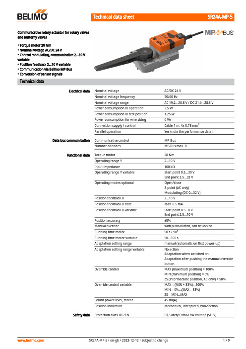
SR24A-MP-5Communicative rotary actuator for rotary valves and butterfly valves• Torque motor 20 Nm• Nominal voltage AC/DC 24 V• Control modulating, communicative 2...10 V variable• Position feedback 2...10 V variable • Communication via Belimo MP-Bus • Conversion of sensor signalsTechnical dataElectrical dataNominal voltageAC/DC 24 V Nominal voltage frequency 50/60 HzNominal voltage rangeAC 19.2...28.8 V / DC 21.6...28.8 V Power consumption in operation 3.5 W Power consumption in rest position 1.25 W Power consumption for wire sizing 6 VAConnection supply / control Cable 1 m, 4x 0.75 mm²Parallel operationYes (note the performance data)Data bus communicationCommunicative control MP-Bus Number of nodesMP-Bus max. 8Functional dataTorque motor 20 Nm Operating range Y 2...10 V Input impedance100 kΩOperating range Y variable Start point 0.5...30 V End point 2.5...32 V Operating modes optionalOpen/close3-point (AC only)Modulating (DC 0...32 V)Position feedback U 2...10 V Position feedback U note Max. 0.5 mA Position feedback U variable Start point 0.5...8 V End point 2.5...10 V Position accuracy ±5%Manual override with push-button, can be locked Running time motor 90 s / 90°Running time motor variable 90...350 sAdaptation setting range manual (automatic on first power-up)Adaptation setting range variableNo actionAdaptation when switched onAdaptation after pushing the manual override buttonOverride controlMAX (maximum position) = 100%MIN (minimum position) = 0%ZS (intermediate position, AC only) = 50%Override control variableMAX = (MIN + 33%)...100%MIN = 0%...(MAX – 33%)ZS = MIN...MAX Sound power level, motor 45 dB(A)Position indicationMechanical, integrated, two-section Safety dataProtection class IEC/ENIII, Safety Extra-Low Voltage (SELV)Safety dataPower source ULClass 2 Supply Degree of protection IEC/EN IP54Degree of protection NEMA/UL NEMA 2Enclosure UL Enclosure Type 2EMCCE according to 2014/30/EUCertification IEC/EN IEC/EN 60730-1 and IEC/EN 60730-2-14UL ApprovalcULus according to UL60730-1A, UL60730-2-14 and CAN/CSA E60730-1The UL marking on the actuator depends on the production site, the device is UL-compliant in any case Type of actionType 1Rated impulse voltage supply / control 0.8 kV Pollution degree 3Ambient humidity Max. 95% RH, non-condensing Ambient temperature -30...50°C [-22...122°F]Storage temperature -40...80°C [-40...176°F]Servicingmaintenance-free Mechanical dataConnection flange F05WeightWeight 1.0 kg•••••••Safety notesThis device has been designed for use in stationary heating, ventilation and air-conditioning systems and must not be used outside the specified field of application, especially in aircraft or in any other airborne means of transport.Outdoor application: only possible in case that no (sea) water, snow, ice, insolation or aggressive gases interfere directly with the device and that it is ensured that the ambient conditions remain within the thresholds according to the data sheet at any time.Only authorised specialists may carry out installation. All applicable legal or institutional installation regulations must be complied with during installation.The switch for changing the direction of rotation may only be operated by authorisedspecialists. The direction of rotation must not in particular be reversed in a frost protection circuit.The device may only be opened at the manufacturer's site. It does not contain any parts that can be replaced or repaired by the user.Cables must not be removed from the device.The device contains electrical and electronic components and must not be disposed of as household refuse. All locally valid regulations and requirements must be observed.Product featuresOperating modeConventional operation:The actuator is connected with a standard control signal of 0...10 V and drives to the position defined by the control signal. The measuring voltage U serves for the electrical display of the actuator position 0.5...100% and as control signal for other actuators.Operation on Bus:The actuator receives its digital control signal from the higher level controller via the MP-Bus and drives to the position defined. Connection U serves as communication interface and does not supply an analogue measuring voltage.Converter for sensors Connection option for a sensor (passive or active sensor or switching contact). The MPactuator serves as an analogue/digital converter for the transmission of the sensor signal viaMP-Bus to the higher level system.Parametrisable actuators The factory settings cover the most common applications. Single parameters can be modifiedwith the Belimo service tools MFT-P or ZTH EU.Simple direct mounting Simple direct mounting on the rotary valve or butterfly valve with mounting flange. Themounting orientation in relation to the fitting can be selected in 90° steps.Manual override Manual override with push-button possible (the gear train is disengaged for as long as thebutton is pressed or remains locked).Adjustable angle of rotation Adjustable angle of rotation with mechanical end stops.High functional reliability The actuator is overload protected, requires no limit switches and automatically stops whenthe end stop is reached.Home position The first time the supply voltage is switched on, i.e. at the time of commissioning, the actuatorcarries out an adaptation, which is when the operating range and position feedback adjustthemselves to the mechanical setting range.The actuator then moves into the position defined by the control signal.Factory setting: Y2 (counter-clockwise rotation).Adaptation and synchronisation An adaptation can be triggered manually by pressing the "Adaptation" button or with the PC-Tool. Both mechanical end stops are detected during the adaptation (entire setting range).Automatic synchronisation after pressing the manual override button is configured. Thesynchronisation is in the home position (0%).The actuator then moves into the position defined by the control signal.A range of settings can be adapted using the PC-Tool (see MFT-P documentation) AccessoriesGateways Description TypeGateway MP to BACnet MS/TP UK24BACGateway MP to Modbus RTU UK24MOD Electrical accessories Description TypeAuxiliary switch 1x SPDT add-on S1AAuxiliary switch 2x SPDT add-on S2AFeedback potentiometer 140 Ω add-on P140AFeedback potentiometer 1 kΩ add-on P1000AFeedback potentiometer 10 kΩ add-on P10000AMP-Bus power supply for MP actuators ZN230-24MPTools Description TypeService tool, with ZIP-USB function, for parametrisable andcommunicative Belimo actuators, VAV controller and HVAC performancedevicesZTH EUBelimo PC-Tool, Software for adjustments and diagnostics MFT-PAdapter for Service-Tool ZTH MFT-CConnecting cable 5 m, A: RJ11 6/4 ZTH EU, B: 6-pin for connection to service socket ZK1-GENConnecting cable 5 m, A: RJ11 6/4 ZTH EU, B: free wire end forconnection to MP/PP terminalZK2-GENSR24A-MP-5Wire colours:1 = black 2 = red 3 = white 5 = orangeElectrical installationSupply from isolating transformer.Parallel connection of other actuators possible. Observe the performance data.Direction of rotation switch is covered. Factory setting: Direction of rotation Y2.Wiring diagrams MP-BusAC/DC 24 V, modulatingFunctionsFunctions with basic values (conventional mode)Override control with AC 24 V with relay contactsOverride control with AC 24 V with rotary switch Control remotely 0...100% withpositioner SG..Functions with basic values (conventional mode)Minimum limit with positioner SG..Primary/secondary operation (position-dependent)Control with 4...20 mA via external resistorCaution:The operating range must be setto DC 2...10 V.The 500 Ohm resistor convertsthe 4...20 mA current signal to avoltage signal DC 2...10 V.Functional checkProcedure1. Connect 24 V to connections 1and 22. Disconnect connection 3:– with direction of rotation L:Actuator rotates to the left– with direction of rotation R:Actuator rotates to the right3. Short-circuit connections 2and 3:– Actuator runs in oppositedirection•••••Functions with specific parameters (Parametrisation necessary)Connection on the MP-Bus MP-Bus Network topologyMax. 8 MP-Bus nodes There are no restrictions for the network topology (star, ring, tree or mixed forms are permitted).Supply and communication in one and the same 3-wire cable • no shielding or twisting necessary• no terminating resistors requiredConnection of active sensorsConnection of external switching contactSupply AC/DC 24 VOutput signal 0...10 V (max.0...32 V)Resolution 30 mVSwitching current 16 mA @ 24VStart point of the operatingrange must be parametrised onthe MP actuator as ≥0.5 VConnection of passive sensors1) Depending on the type2) Resolution 1 OhmCompensation of the measuredvalue is recommendedSR24A-MP-5Functions with specific parameters (Parametrisation necessary)Override control and limiting with AC 24 V with relay contactsControl open/closeOverride control and limiting with AC 24 V with rotary switchCaution:The "Close" function is only guaranteed if the start point of the operating range is defined as min. 0.5 V.Control 3-point with AC 24 VPosition control: 90° = 100s Flow control: Vmax = 100sFunctionsSR24A-MP-5 Operating controls and indicators1Direction of rotation switchSwitch over:Direction of rotation changes2Push-button and LED display greenOff:No power supply or malfunctionOn:In operationPress button:Triggers angle of rotation adaptation, followed by standard mode3Push-button and LED display yellowOff:Standard modeOn:Adaptation or synchronisation process activeFlickering:MP-Bus communication activeFlashing:Request for addressing from MP clientPress button:Confirmation of the addressing4Manual override buttonPress button:Gear train disengages, motor stops, manual override possibleRelease button:Gear train engages, standard mode5Service plugFor connecting parametrisation and service toolsCheck power supply connection2 Off and3 On Possible wiring error in power supplyServiceTool connection The actuator can be parametrised by ZTH EU via the service socket.For an extended parametrisation the PC tool can be connected.Connection ZTH EU / PC-ToolSR24A-MP-5 DimensionsFurther documentation• Overview MP Cooperation Partners• Tool connections• Introduction to MP-Bus Technology• The complete product range for water applications• Data sheets for ball valves• Installation instructions for actuators and/or ball valves• General notes for project planning。
陀螺仪

【规格】
1. 外形尺寸:26mm*24mm*9mm
2. 重量:12g
3. 工作电压和电流:DC 4.5-6.5V,工作电流≈50mA,最大电流<100mA
4. 适用舵机:模拟舵机(频率 50Hz)、数码舵机(频率 333Hz),舵机中点 1520us
1
User Manual of Gyro G3
Doc Ver. HW-100A-G3-091228 Page 2 of 7
2
User Manual of Gyro G3
【各种工作模式下 LED 的状态】
在不同模式下,陀螺仪面板上最右侧的 LED #S 的状态不同。如下表所示(LED 序号请
参见第 2 页的图示)。
【免责声明】 模型运动本身具有一定的风险,该运动要求玩家具有一定的专业知识和技能。本产品在
设计时已经采取多重安全保护措施,但设备的工作环境和条件差别很大,无法完全预计。我 们强烈建议您尽可能为设备提供良好的安装和运行条件, 确保供电以及控制信号的稳定可 靠, 确认飞行场地的安全。 本公司不承担因使用陀螺仪而造成的直接及间接损失。本产品 一经拆封使用,视同您已认可以上全部条款。
警告:陀螺仪通电前,请务必将遥控器置为方向锁定模式,否则陀螺仪无法正常工作。 4. 一些老款或者简易的遥控器上可能没有陀螺仪感度值设置的选项,此时可以通过调整感
度通道行程量(ATV)控制陀螺仪的敏感度。 以下范例使用 Futaba FF6 遥控器,进入通道行程量(ATV)的功能项,分别设定
CH5(感度通道)的 ATV 为一般飞行模式(陀螺仪处于方向锁定模式,陀螺仪敏感度 72%,CH5 开关扳向前方)及 Idle 飞行模式(陀螺仪处于普通模式,陀螺仪敏感度 54%, CH5 开关扳向后方)。使用 CH5 开关切换陀螺仪的敏感度。 注意: 使用 CH5 开关切换陀螺仪的敏感度时,无法同时将一般飞行模式和 Idle 飞行模 式设置为方向锁定模式,CH5 开关必须是一侧为方向锁定模式,一侧为普通模式,而且 方向逆转(REVERSE)功能项中的 CH5 需设置为 NORM (即 NORMAL)。
索佳 GYRO1X 2X 3X 自动全站式陀螺仪 说明书
1!!!!!使 用 说 明 书2!!!!!!!!!!!!!!使 用 说 明 书相关使用说明书y GYRO1X/2X/3X随机配备下列使用说明书:1.《GYRO1X/2X/3X自动全站式陀螺仪使用说明书》介绍自动全站式陀螺仪的操作方法。
2.《SRX系列电子全站仪使用说明书》介绍SRX系列电子全站仪的基本功能及其操作方法。
符号和约定 本说明书使用下列符号和约定::表示操作前应阅读的注意事项和重要内容。
:表示参阅章节的名称。
:表示补充说明。
:表示特别术语或操作的说明。
[软键]等 :表示屏幕显示的功能软键。
{按键}等 :表示操作面板上的按键。
相关说明 y除特别说明外,说明书中的“SRX”均表示“SRX1X/2X/3X”。
y除特别说明外,说明书的“GYRO X”均表示“GYRO1X/2X /3X”。
41.安全操作须知 (1)2.注意事项 (5)3.激光安全信息 (7)4.仪器部件名称 (9)4.1全站式陀螺仪的特点 (9)4.2仪器部件名称 (10)4.3模式结构图 (12)5.基本操作 (13)5.1按键基本功能 (13)6.电池充电 (15)7.测前准备和结束测量 (17)7.1仪器连接 (17)7.2陀螺测量前准备工作 (19)7.3陀螺程序启动与退出 (21)7.4结束陀螺测量 (23)8.真北方向测定 (24)8.1方位角显示 (25)8.2真北方向测定 (26)9.仪器常数测定 (33)10.错误信息 (38)11.故障处理 (39)11.1更换保险丝 (40)512.仪器检查 (41)12.1悬挂带检查 (42)12.2检查模式 (42)13.标准配置 (45)14.技术指标 (47)15.规范 (49)16.附录:陀螺仪原理 (50)61.为确保安全操作,避免造成人身伤害或财产损失,本说明书使用“警告”或“注意”来提示应遵循的条款。
在阅读本说明书主要内容之前,请首先弄清这些提示的含义。
提示含义本符号用于需特别注意条款的提示,有关细节说明随符号给出。
陀螺仪的使用方法
陀螺仪,也被称为角速度传感器,是一种用于测量和控制物体在相对惯性空间中的角运动的惯检测性器件。
它的基本操作方法包括:
1. 放置和安装:将陀螺仪放置在稳定的平台上,按照指南进行正确的安装。
2. 连接电源:根据陀螺仪的型号和使用说明,将其连接到适当的电源。
3. 校准:初次使用或长时间未使用后,需要进行校准以确保测量结果的准确性。
4. 启动和停止测量:在准备好后,可以启动陀螺仪进行测量;在测量完成后,记得停止测量以保护设备。
5. 数据处理和分析:收集的数据需要经过处理和分析才能得到有用的信息。
正确操作和使用陀螺仪可以保证其测量结果的准确性和稳定性。
具体的操作步骤和注意事项应根据陀螺仪的型号和使用说明来确定。
此外,要注意的是,陀螺仪的使用并不复杂,但是需要一些基本的理解和维护知识。
Model 393B12 Seismic高敏度陀螺仪产品说明书

Model 393B12Seismic, high sensitivity, ceramic shear ICP® accel., 10 V/g, 0.15 to 1k Hz,Installation and Operating ManualFor assistance with the operation of this product,contact PCB Piezotronics, Inc.Toll-free: 800-828-884024-hour SensorLine: 716-684-0001Fax: 716-684-0987E-mail:************Web: The information contained in this document supersedes all similar information that may be found elsewhere in this manual.Total Customer Satisfaction – PCB Piezotronics guarantees Total Customer Satisfaction. If, at any time, for any reason, you are not completely satisfied with any PCB product, PCB will repair, replace, or exchange it at no charge. You may also choose to have your purchase price refunded in lieu of the repair, replacement, or exchange of the product. Service – Due to the sophisticated natureof the sensors and associated instrumentation provided by PCB Piezotronics, user servicing or repair is not recommended and, if attempted, may void the factory warranty. Routine maintenance, such as the cleaning of electrical connectors, housings, and mounting surfaces with solutions and techniques that will not harm the physical material of construction, is acceptable. Caution should be observed to insure that liquids are not permitted to migrate into devices that are not hermetically sealed. Such devices should only be wiped with a dampened cloth and never submerged or have liquids poured upon them.Repair – In the event that equipment becomes damaged or ceases to operate, arrangements should be made to return the equipment to PCB Piezotronics for repair. User servicing or repair is not recommended and, if attempted, may void the factory warranty.Calibration – Routine calibration of sensors and associated instrumentation is recommended as this helps build confidence in measurement accuracy and acquired data. Equipment calibration cycles are typically established by the users own quality regimen. When in doubt about a calibration cycle, a good “rule of thumb” is to recalibrate on an annual basis. It is also good practice to recalibrate after exposure to any severe temperature extreme, shock, load, or other environmental influence, or prior to any critical test.PCB Piezotronics maintains an ISO-9001 certified metrology laboratory and offers calibration services, which are accredited by A2LA to ISO/IEC 17025, with full traceablility to N.I.S.T. In addition to the normally supplied calibration, special testing is also available, such as: sensitivity at elevated or cryogenic temperatures, phase response, extended high or low frequency response, extended range, leak testing, hydrostatic pressure testing, and others. For information on standard recalibration services or special testing, contact your local PCB Piezotronics distributor, sales representative, or factory customer service representative. Returning Equipment – Following these procedures will insure that your returned materials are handled in the most expedient manner. Before returning any equipment to PCB Piezotronics, contact your local distributor, sales representative, or factory customer service representative to obtain a Return Warranty, Service, Repair, andReturn Policies and InstructionsMaterials Authorization (RMA) Number. This RMA number should be clearly marked on the outside of all package(s) and on the packing list(s) accompanying the shipment. A detailed account of the nature of the problem(s) being experienced with the equipment should also be included inside the package(s) containing any returned materials.A Purchase Order, included with the returned materials, will expedite the turn-around of serviced equipment. It is recommended to include authorizationon the Purchase Order for PCB to proceed with any repairs, as long as theydo not exceed 50% of the replacement cost of the returned item(s). PCB will provide a price quotation or replacement recommendation for any item whose repair costs would exceed 50% of replacement cost, or any item that is not economically feasible to repair. For routine calibration services, the Purchase Order should include authorization to proceed and return at current pricing, which can be obtained from a factory customer service representative.Warranty – All equipment and repair services provided by PCB Piezotronics, Inc. are covered by a limited warranty against defective material and workmanship for a period of one year from date of original purchase. Contact PCB for a complete statement of our warranty. Expendable items, such as batteries and mounting hardware, are not covered by warranty. Mechanical damage to equipment due to improper use is not covered by warranty. Electronic circuitry failure caused by the introduction of unregulated or improper excitation power or electrostatic discharge is not covered by warranty. Contact Information – International customers should direct all inquiries to their local distributor or sales office. A complete list of distributors and offices can be found at . Customers within the United States may contact their local sales representative ora factory customer service representative. A complete list of sales representatives can be found at . Toll-free telephone numbers for a factory customer service representative, in the division responsible for this product, can be found on the title page at the front of this manual. Our ship to address and general contact numbers are:PCB Piezotronics, Inc.3425 Walden Ave.Depew, NY 14043 USAToll-free: (800) 828-884024-hour SensorLine SM: (716) 684-0001 Website: E-mail:************DOCUMENT NUMBER: 21354 DOCUMENT REVISION: B ECN: 17900。
凌思 LINS-F500型光纤陀螺惯性测量单元 说明书

LINS-F500型光纤陀螺惯性测量单元规格说明书无锡凌思科技有限责任公司LINS-F500光纤惯组技术指标1简介光纤陀螺作为一种新型全固态陀螺,具有启动快、测量范围广和可靠性高等优点。
其中,LINS-F500型光纤陀螺惯组是针对中等精度应用背景的需求,采用三轴共用技术设计,成本低、性能稳定;结构上采用光路、电路一体封装,结构简单,安装方便,可应用与小型导弹、制导炸弹的导航制导、姿态测量与控制等系统中。
1.1 应用范围该说明书仅适用于LINS-F500型产品,包含了性能指标、技术条件、外形尺寸及安装使用。
其中,技术条件包括产品的环境范围、电气性能、物理特征。
1.2 主要参数1.2.1 光纤陀螺仪主要性能指标:LINS-F500主要性能指标1.2.2 力学测试 1.2.2.1 正弦扫描振动陀螺按振动方向通过工装固定在振动台上,陀螺仪进行3个方向的正弦扫描,分别对应于X 轴、Y 轴、Z 轴方向。
振动步骤;振动台加激磁,给陀螺仪加电,预热一定时间后(陀螺启动时间),测试陀螺仪输出值,约5min ;进行正弦振动。
振动条件:20Hz-2000Hz ,扫描时间5min ,幅值4.2g 。
振动过程中,记录陀螺仪输出。
随机振动振动频率:20Hz~2000Hz 振动时间:各轴分别为5min 振动方向:X 、Y 、Z 轴 振动谱图:见附图1附图1振动谱图 指标要求:光纤陀螺在20HZ ~2000Hz 范围正弦扫频扫描无谐振;随机振动:振中零偏值与前后零偏平均值的绝对值≤0.1º/h ,振前与振后零偏差的绝对值≤0.05 º/h。
1.2.2.2 机械冲击按表2的要求。
表2冲击试验条件功率谱密度 0.06g 2Hz冲击过程中,产品处于通电状态,完成机械冲击产品,应能正常工作,冲击前后零偏差的绝对值≤0.05 º/h。
2. 通讯协议注:1. 加速度值单位是g,角速度值单位是弧度/秒,姿态角度单位是弧度.2. 串口配置是1bit起始位,8bit数据,无校验位,1bit停止位,默认波特率1152003、接线定义4、产品外形尺寸LINS-F500 IMU外形尺寸图。
GA510尾锁陀螺仪说明书
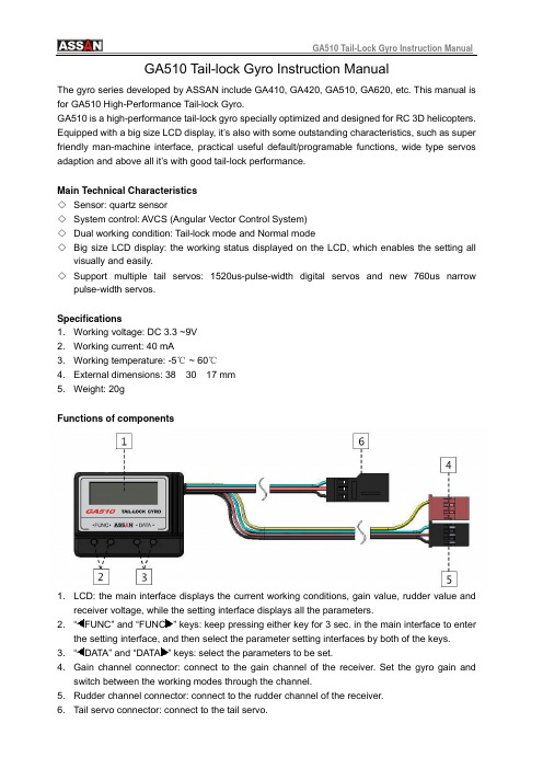
GA510 Tail-lock Gyro Instruction ManualThe gyro series developed by ASSAN include GA410, GA420, GA510, GA620, etc. This manual is for GA510 High-Performance Tail-lock Gyro.GA510 is a high-performance tail-lock gyro specially optimized and designed for RC 3D helicopters. Equipped with a big size LCD display, it’s also with some outstanding characteristics, such as super friendly man-machine interface, practical useful default/programable functions, wide type servos adaption and above all it’s with good tail-lock performance.Main Technical Characteristics◇ Sensor: quartz sensor◇ System control: AVCS (Angular Vector Control System) ◇ Dual working condition: Tail-lock mode and Normal mode◇ Big size LCD display: the working status displayed on the LCD, which enables the setting allvisually and easily. ◇ Support multiple tail servos: 1520us-pulse-width digital servos and new 760us narrowpulse-width servos.Specifications1.Working voltage: DC 3.3 ~9V 2. Working current: 40 mA3. Working temperature: -5℃ ~ 60℃4. External dimensions: 38× 30 × 17 mm 5. Weight: 20gFunctions of componentsdisplays the current working conditions, gain value, rudder value and2. 1.LCD: the main interface receiver voltage, while the setting interface displays all the parameters.“FUNC” and “FUNC ” keys: keep pressing either key for 3 sec. in the main interface to enter3. the setting interface, and then select the parameter setting interfaces by both of the keys. “DATA” and “DATA ” keys: select the parameters to be set.4. Gain channel connector: connect to the gain channel of the receiver. Set the gyro gain and5. of the receiver. switch between the working modes through the channel.Rudder channel connector: connect to the rudder channel 6. Tail servo connector: connect to the tail servo.Installationng GA510 Tail-lock Gyro, please stick the gyro to the stable place of the helicopter with isplay and setting st powered on first), GA510 will display thet move When installi the double-sided tape inside the packing box. The bottom of the gyro shall be perpendicular to the main axis of the helicopter (see the figure below). The G510 Tail-lock Gyro used on the RC electric helicopter shall be at least 10cm away from the motor. Do not install the gyro at the exhaust outlet or any places of heat to avoid the possible disturbance.D 1. Power onWhen the gyro’s powered on (the transmitter mu following interfaces in sequence. Pay attention that before the main interface appeared, don’the stickers, the gyro and the helicopter anyway.2. Error promptIf there is any failure during the power-on process, the following error prompt will appear:The rudder channel is not connected properly or transmitter power wasn’t turnedon. Please check the connection of the signal wire between the gyro and the rudder channel of the receiver or turn on transmitter power.The gain channel is not connected properly. Please check the connection of thesignal wire between the gyro and the gain channel in the receiver.Internal error in gyro. If the problem cannot be fixed after turn off the power andrestart, please return the gyro to the manufacturer for repair.3. Main interfaceGain valueRudder valueReceiver battery voltageWorking ModeTwo working mode as the follows:Tail-lock mode Normal mode4. FunctionPress “FUNC” or “FUNC” for 3 sec. to enter the setting interface, then selected by the two keys. GA510 gyro’s functions include:Gyro control directionsServo typesServo center trimTwo-direction servo limit adjustmentAdjustment of rudder stick response smoothnessStatic drift correction5. Setting1) Gyro control directionsThe gyro has two movement directions, namely NOR and REV. Lift the helicopter and turn the head of the helicopter left. If the sway of the tail servo is in the same direction when turning right the rudder controller on the transmitter, the control direction of the gyro is corrected set. If the direction is not correct, press “DATA” or “DATA” key to change the setting value of the control directions. The step above is most important. If the control direction of the gyro is wrong , the helicopter may have the danger of rotating at high speed when taking off, therefore please check it again whether the control direction of the gyro is in correctly set.2) Selection of servo typesThe typical marketed tail servos can be classified into 3 different types according to the frame rate / pulse width, see the table below. If you used is not included in the table, please select the type according to the applicable frame rate / pulse width provided by the manufacturer. Be careful that the incorrect selection may cause the damage or decrease the performance or life of the servo.1520us / 250Hz 1520us / 333Hz 760us / 333HzJR 810G Airtionics 94758 Futaba BLS251JR 2700G Airtionics 94761 Futaba S9251JR 8700G Futaba S3153 Futaba S9256Sky HDS-577 Futaba S3154 LogicTech 6100GSky HDS-877 Futaba S9253 MKS DS8910Futaba S9254Futaba S9257Futaba S9650JR 3400GJR 8900GHitec HS-5925MGHitec HS-6965HBLogicTech 2100GRobbe FS61BBSanwa ERG-WRX3) Servo center trimPress “DATA” or “DATA” key to adjust the center value of the servo between -100 and 100. It is recommended to adjust the rocker arm position of the servo at first. After the center position is basically appropriate, trim the center position with this function. Try to avoid the large-scale adjustment on the center of the servo.4) Two-direction servo limit adjustmentTurn the rudder stick full rudder to one direction, then press “DATA” or “DATA” to adjust the limit to make the servo reach the maximum movement limit of the tail pitch sliding sleeve in this direction, and ensure that no over limit occurs in the process. Set the other direction with the same method. The adjustable range of the two-direction limits is 30% - 160%.5) Adjustment of rudder stick response smoothnessPress “DATA” or “DATA” to adjust the response smoothness of the rudder stick within the range of 0% - 25%. This function adjusts the “hard” and “soft” feel in the response of the gyro to the rudder stick. The user may adjust the smoothness according to his own control feeling.6) Static drift correctionIn Tail-lock mode, if the tail is slowly drifting when the helicopter in hovering, make correction with this function. Adjust with the small setting value for several times to reach the satisfactory hovering static state.Have fun!!ASSAN ELECTRONIC CONTROL TECHNIC CO., LTD。
PmodGYRO2 高性能单轴陀螺仪说明书
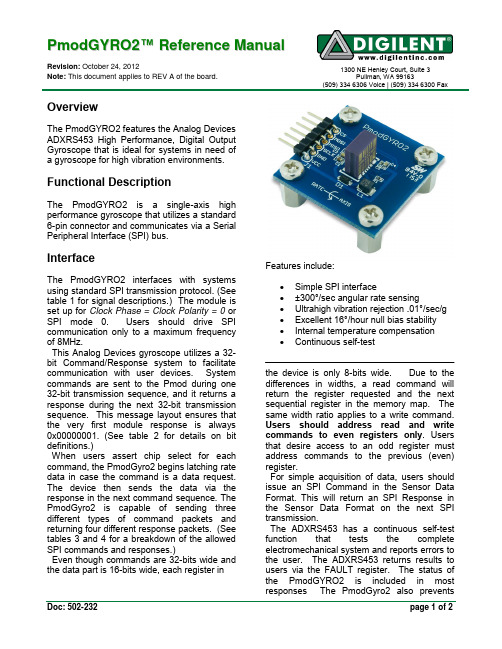
P m o d G Y R O 2™ R e f e r e n c e M a n u a lRevision: October 24, 2012Note: This document applies to REV A of the board.1300 NE Henley Court, Suite 3Pullman, WA 99163(509) 334 6306 Voice | (509) 334 6300 FaxDoc: 502-232page 1 of 2OverviewThe PmodGYRO2 features the Analog Devices ADXRS453 High Performance, Digital Output Gyroscope that is ideal for systems in need of a gyroscope for high vibration environments.Functional DescriptionThe PmodGYRO2 is a single-axis high performance gyroscope that utilizes a standard 6-pin connector and communicates via a Serial Peripheral Interface (SPI) bus.InterfaceThe PmodGYRO2 interfaces with systems using standard SPI transmission protocol. (See table 1 for signal descriptions.) The module is set up for Clock Phase = Clock Polarity = 0 or SPI mode 0. Users should drive SPI communication only to a maximum frequency of 8MHz.This Analog Devices gyroscope utilizes a 32-bit Command/Response system to facilitate communication with user devices. System commands are sent to the Pmod during one 32-bit transmission sequence, and it returns a response during the next 32-bit transmission sequence. This message layout ensures that the very first module response is always 0x00000001. (See table 2 for details on bit definitions.)When users assert chip select for each command, the PmodGyro2 begins latching rate data in case the command is a data request. The device then sends the data via the response in the next command sequence. The PmodGyro2 is capable of sending three different types of command packets and returning four different response packets. (Seetables 3 and 4 for a breakdown of the allowed SPI commands and responses.)Even though commands are 32-bits wide and the data part is 16-bits wide, each register inFeatures include:∙ Simple SPI interface∙ ±300°/sec angular rate sensing∙ Ultrahigh vibration rejection .01°/sec/g ∙ Excellent 16°/hour null bias stability ∙ Internal temperature compensation ∙ Continuous self-testthe device is only 8-bits wide. Due to the differences in widths, a read command will return the register requested and the next sequential register in the memory map. The same width ratio applies to a write command. Users should address read and write commands to even registers only . Users that desire access to an odd register must address commands to the previous (even) register.For simple acquisition of data, users should issue an SPI Command in the Sensor Data Format. This will return an SPI Response in the Sensor Data Format on the next SPI transmission.The ADXRS453 has a continuous self-test function that tests the complete electromechanical system and reports errors to the user. The ADXRS453 returns results to users via the FAULT register. The status of the PmodGYRO2 is included in most responses The PmodGyro2 also preventsPmodGYRO2 Reference Manual page 2 of 2Copyright Digilent, Inc. All rights reserved. Other product and company names mentioned may be trademarks of their respective owners.temporary spikes in data from causing a failing status response by filtering raw data from the self-test before sending a pass/fail status. The module stores both the raw data and the filtered data in the HICSTx and LOCSTx registers. Users may access this data should they be concerned about these energy spikes. The temperature sensor data is useful for temperature compensation of the rate data and is also directly available to the user. To get the temperature sensor data users must simply execute a read command of the TEMx registers from the device.Table 1: Interface Connector SignalDescriptionNote: For more information on the GYRO2 module interface, see the ADXRS453 datasheet available online from Analog Devices at .Table 2: SPI Bit DefinitionsTable 3: SPI CommandsTable 4: SPI Responses。
南方陀螺仪使用说明书

仪器常数测试方法同精度测试操作方法相似,只是在 4.5 条数据Байду номын сангаас处理上有所区别,按 4.1~4.4 进行寻北测试后,测试结果记为 αgi 则:
Ki= a gi a N …………………………………………
(4)
式中: αN—基准边方位角; Ki—第 i 次测量得到的仪器常数。 仪器常数K为:
南方陀螺仪使用说明书
———————————————————————————————— 作者: ———————————————————————————————— 日期:
ﻩ
ASG-15 陀螺全站仪使用说明书
目次
1概述
1.1 功能和用途 1.2 主要性能参数
2 仪器组成 3工作原理 4使用方法
4.1 三脚架架设 4.2 陀螺全站仪主机架设 4.3 纬度输入 4.4 测量程序 4.5 数据处理 4.6 仪器撤收
勿大角度倾斜或倒置),然后将其平稳置于三脚架上。 b.取出全站仪主机。将全站仪对照定位孔放置于陀螺仪主机上并
锁紧。 c.陀螺全站仪粗对北。取出包装箱内的磁罗盘,按照其使用说明
书规定的方法,确定当地大致北向;将陀螺寻北仪主机粗对北标记置 于大致北向(北向可以借助磁罗盘确定,其使用方法见磁罗盘使用说 明书);然后顺时针方向旋转锁紧三脚架上的三个对心手轮。
和矿山贯通测量等领域。
1.2 主要性能参数
仪器主要技术指标见表 1。
表 1 陀螺全站仪主要技术指标表
寻北精度
≤15 (1)
寻北时间
≤10min
工作方式
全自动
工作电源
24V DC
飞机爱好者A3 EVO 6 轴陀螺仪使用说明书
中文使用说明书版本:V1.0 2021/10感谢您购买和使用我们的产品。
A3 EVO是一款专门为遥控固定翼模型飞行设计的高性能、功能强大的6轴陀螺仪产品。
为了让您更好地了解和使用本产品和安全飞行,请认真阅读本说明书并按说明书的要求进行相关设置。
注意事项•遥控飞机模型不是玩具!螺旋桨高速旋转带来的潜在风险相当高,它们可能会导致严重的伤害,一切的使用要符合并遵守共同的安全规则和相关法规。
我们建议您在第一次使用我们的陀螺仪进行飞行时,寻求具有丰富飞行经验的玩家的指导和帮助;•A3 EVO在通电后需要进行精确的陀螺仪校准,所以,在接通飞机电源后,请保持飞机静止,等待蓝灯闪烁若干秒完成校准后,才能开始飞行,如果在这个阶段陀螺仪检测到有轻微的移动,蓝灯会一直保持常亮,直至飞机不再移动才重新开始校准过程,尽管如此,开机初始化阶段只需要保持静止即可,并不需要将飞机水平放置;•A3 EVO在通电后还需要进行摇杆中位校准,所以,通电前,先把发射机的所有摇杆放在中间位置,油门摇杆放在最低,打开发射机电源,然后再接通飞机电源,在初始化过程中不要移动任何摇杆直至初始化完成;•安装完成后请务必逐一检查副翼、升降、方向三个通道的陀螺仪修正方向是否正确!并且养成在每次起飞前都检查确认陀螺仪方向的习惯,错误的陀螺仪方向将会导致失控甚至坠机!•安装陀螺仪后,由于舵机的修正动作明显增加,将导致工作电流增大,请务必确保UBEC或电调的内置BEC能够提供足够的输出电流,否则可能造成电压不稳定,对飞行带来安全隐患。
为了获得更加稳定的电压,建议将配送的大电容插在陀螺仪或接收机的任意一个空闲的接口上。
使用一片附带的双面胶将陀螺仪牢固地安装在机身内部,安装时应尽量靠近飞机的重心位置,使陀螺仪外壳的三条边与飞机的三个旋转轴完全平行,并且保持陀螺仪与安装平面平行,尽量减小安装角度的误差,这样可以更好地发挥陀螺仪的性能。
A3 EVO可以水平或垂直安装,但无论是哪种安装方式,都要保证带按钮的一侧短边正对机头方向,即飞行的前进方向,排针指向后方,否则自动平衡模式和自动吊机模式将不能正常工作。
PowerBox iGyro 三轴陀螺仪产品说明书

99 | Author:COLIN STRAUS Photographs:COLIN STRAUSPOWERBOXIGYROColin Straus takes a look at the new and much talked about iGyro from PowerBoxIfirst heard of the development of this new three-axis gyrosystem early in 2012, and keenly awaited its release, as Ihave been using PowerBox products for many years nowwith great success, and expected the new iGyro to be just aseffective as the other products I have used.The iGyro is purpose designed for use in fixed wing aircraft,and offers independently adjustable gyro stabilisation on roll,pitch and yaw axis, to both make the model much steadier inbumpy conditions and to make the overall flight path smootherand more realistic.WHAT WILL IT DO FOR ME?One of the main features of the iGyro is that it has dual functionality, both normal and heading modes being incorporated. Normal mode is operative when the transmitter sticks are moved even slightly from the neutral position and results in any deviation from the model’s flight path being damped. So for example any effects caused by gusts of wind, turbulence etc. will be damped out and made much less severe.Heading mode takes over when the sticks are at neutral and will maintain the model’s last commanded attitude, for example if the model is in knife edge flight the elevator will be trimmed by the iGyro to counteract any pitching moment caused by the rudderdeflection.Further to this, the iGyro will automatically compensatewhen flaps or airbrakes etc. are deployed, there is no need to have any mixing of functions, and in fact any such mixes should be disabled. Available as an optional extra is a GPS sensor, which is designed to be used in conjunction with the iGyro; primarily to enable the gyro gainto be varied depending upon theflying speed of the model.Packaged in the now familiar PowerBox two-tone blue boxing the iGyro is a neat and compact unit in an anodised aluminium case, and is fitted with a nice clear OLED display. It has inputs for most modern radio systems, including Futaba S-Bus, Spektrum, Multiplex M-Link, Jeti and Graupner HoTT , and single or twin receivers can be used as required, the use of twin receivers offering increased safety.Remaining inputs are forthe optional GPS sensor and a Bus 2 socket, whilst outputs total five, two aileron, two elevator and one rudder, there being one final connection for the SensorSwitch used during programming, this can then be disconnected as it is not required once set-up is completed. Further components included are four double-ended input leads, two for input and two for output, a USB interface adapter for software updates as well as servo tape to securely mount the iGyro. The optional GPS sensor is contained within a neatly moulded case, and has a single lead to connect to the The standard iGyro package includes the unit itself, as well as SensorSwitch for programming, USB interface andleads, tape etcThe compact nature and high quality finish of the iGyro are evident Reverse of the unit has all connections very clearly marked Optional GPS sensor is small and is very neatly packaged in this moulded case100 |iGyro, the sensor again being secured in the model with servotape. The supplied instruction manual is in both English andGerman and as per usual with PowerBox manuals is both clearand informative.ON TESTTo test out the iGyro I decided to install it into my FeiBao F9FPanther, as although this model flies superbly and is supersmooth in most flight regimes, the one weakness it suffers fromis its vulnerability to crosswinds when landing. If there is any significant crosswind the Panther can be a real handful during the approach, with aileron and rudder controls being used constantly to keep the wings level all the way to touchdown, this possibly being due to the amount of dihedral and the large tip tanks.I had previously fitted a single axis gyro for the ailerons and this had helped, but was still not a complete cure, so having a three axis gyro with the features of the iGyro would hopefully eliminate this less than welcome flying characteristic.Usefully the iGyro is quite flexible with regard to how it is installed as it can function as a standalone unit or in conjunction with a PowerBox power supply system, and this can be either a conventional unit such as the PowerBox Competition or an SRS unit such as the PowerBox Cockpit SRS.Installation of the unit into the Panther was verystraightforward, as the unit is nice and compact, asis the GPS module, and there is plenty of room in thelarge fuselage of the model. As I use Futaba radio an R7008SB (S-Bus) receiver was installed alongside aPowerBox Cockpit SRS system, these components all being compatible, and enabling very simple inter-connection as they all use serial bus communication. A single lead is used from the receiver to the iGyro, whilst two leads run from the iGyro to the Cockpit, offering a degree of redundancy, as only one lead is actually required for full operation. Note that if the iGyro is being used on a standalone basis or with a conventional PowerBox power supply system that up to five leads would be required, for ailerons, elevator and Initial programming screen enables the various menus to be accessedGyro setting screen provides information on direction of gyro effect, as well as the amount of gain in both normal and heading modes Airspeed setting screen enables the maximum airspeed reached to be read and then reset before the next flightThe first of four screens of the input mapping menu, where the functions, gain controls and flight mode switch are selectedInstallation into the Panther test model was very straightforward, using the double-sided tape supplied101 | FEBRUARY 2013rudder, but using the Cockpit SRS enables serial bus communication and the use of only two leads. The GPS unit was installed alongside the iGyro, and a single lead connects the two, whilst the SensorSwitch was only plugged in during set-up.Initial set-up was carried out following thecomprehensive instructions, initialling selecting the radio system being used and then going on to set the output to digital output for operation with the Cockpit SRS. This mode means that servos cannot be connecteddirectly to the outputs from the iGyro, as the output is in a serial digital format that the SRS system utilises. The exact positioning and orientation of the iGyro itself is not critical, apart from the requirement that it be mounted at 90 degrees to the models centreline, then the software within the iGyro is used to confirm the orientation of the iGyro within the model, this being quite straightforward.Selecting the wing type comes next as there is a Delta option in the software, if selected this removes theneed to have delta mixing in the transmitter – in fact any delta mixing in the transmitter must be switched off or theheading mode of the iGyro will not function correctly.The next section is the channel assignment, this allows thefive output channels (2 x aileron, 2 x elevator and 1 x rudder)to be assigned to the required radio channels, then the normaland heading gain set-up channels can be assigned to specificcontrols on the transmitter, after which the channel to be usedfor flight modes is selected.The direction of gyro on each axis is now set, this is a criticalstep as having the gyro operate in the reverse direction to thatrequired would cause a fright at best and a lost model at worst,so the settings here should be double checked for safety.The airspeed settings menu enables the effect of the GPSsystem to be adjusted, this system has been developed sothat the gyro gain is automatically changed as the airspeedof the model varies so that the gyro gain is higher when themodel is flying at lower airspeeds and the control surfacesneed more deflection to be effective, the gain then reducing asthe airspeed increases, to avoid any oscillation of the model atincreased airspeed due to the gain being too high.Before I started the in-flight adjustment and setting of theiGyro I carried out a test flight of the Panther with the gyrofunctions disabled to ensure all trims were correctly set, as thisis required to allow the gyro to operate at its optimum, and notto have to fight an out of trim model.With this complete the iGyro was programmed as per theinstructions with a three position switch being used to select the required flight mode, FM 1 being gyro disabled, FM 2 gyro enabled with rudder operating in normal mode only and FM 3 having the rudder gyro functioning both on normal and heading mode.The first set-up flight was made with only the aileron gyro able to function, with the right and left hand sliders on the transmitter being set to adjust normal and heading mode gain respectively. Take-off was made with the flight mode switch set to position 1, so that the gyro was inoperative, once at a safe height and at a steady and fairly slow cruise speed the switch was moved to position 2 and the right slider carefully moved to increase the gain of the gyro until I started to see the wings rock from side to side, signifying that the gain was now too high, at which point I reduced the gain slightly until the wings remained level. This completed setting the normal mode for aileron, but to check the effect of the GPS setting on the gain relating to airspeed I then carried out a couple of full power level passes, watching to see if the wings oscillated at this higher airspeed, which would have required adjustment when back on the ground to the change in sensitivity of the GPS speed compensation. Luckily the model stayed completely stable during these runs, confirming that the GPS setting recommended in the manual was correct. PRODUCT REVIEWGeneral settings screen enables the iGyro orientation to be set, as well as enabling delta or V tail mixing to be selectedReceiver setting screen where the radio being used can be set, and the output changed between analogue and digital (standard or serial bus)After the flight test session the iGyro confirms the maximum speed of the Panther at245 kmh, or just over 150 mph!102FEBRUARY 2013 |。
MINI ONE 中文说明书

3
2、GYDIRECT-----修正方向選擇 注意:先確定舵桿打右時,尾旋翼的方向是正確的右舵。若相反,請由遙控器內部的 Servo Reverse 功能中的 Rudder 項目逆轉,直 到尾舵方向正確為止。
摇头方向
摇头方向
尾翼推进
尾翼推进
選擇項目
內容
NORM
MINI ONE 置于锁尾模式(AVCS,LED 常亮),將直昇機抬起,將機頭向左移動,尾舵應該向右修正,若尾舵向左修
● 把 MINI ONE 连接到接收器上,此时不要把舵机连接到 MINI ONE 上。
is ● 将感度通道分配到发射机上一个两点开关,便于正常模式(Normal)和锁尾(角度向量控制系统 ACVS)模式的切换。
● 确保发射机微调和辅助微调都置零,禁止主翼螺距和尾翼螺距混控。给 MINI ONE 接通电源,打开感度开关,检查发光二级管(LED)
MINI ONE
MEMS AVCS GYRO
istered 前言 MINI ONE 是一款高精度的模型直升飞机陀螺仪,它能带给你最高标准的操作性能。高质量、高性能传感器和控制器,使得 MINI ONE 具备了非常稳定的偏航率而不受外界变量的影响,例如直升机的旋翼旋转速度、十字盘载荷、飞行速度以及风等。这种特点是其作复杂的 g 皮鲁埃特旋转 3 维机动的必备条件。该陀螺仪具备非常优秀的定位能力,其精确性使你感觉非常可靠。 e MINI ONE 提供了两种操作模式:正常模式和锁尾模式。 R 规格和配件 n ● 传感器类型:MEMS U ● 工作电压:4~10 伏,电流﹤60mA ● 工作条件:-10~45 摄氏度 ● 外型尺寸:20.5mm×19.5mm×10mm ● 重 量: 10 克 ● 舵机兼容性:1520us-333Hz、1520us-250Hz、960us-333Hz 和 760us-500Hz 数字舵机; 1520us-71Hz 模拟舵机. ● 配件:泡绵双面胶、不锈钢钢片
70型光纤陀螺仪使用说明书
70型光纤陀螺仪使用说明书编辑整理:尊敬的读者朋友们:这里是精品文档编辑中心,本文档内容是由我和我的同事精心编辑整理后发布的,发布之前我们对文中内容进行仔细校对,但是难免会有疏漏的地方,但是任然希望(70型光纤陀螺仪使用说明书)的内容能够给您的工作和学习带来便利。
同时也真诚的希望收到您的建议和反馈,这将是我们进步的源泉,前进的动力。
本文可编辑可修改,如果觉得对您有帮助请收藏以便随时查阅,最后祝您生活愉快业绩进步,以下为70型光纤陀螺仪使用说明书的全部内容。
FOG—70型光纤陀螺仪使用维护说明书FOG-70型光纤陀螺仪使用维护说明书1.产品名称FOG-70型光纤陀螺仪。
2.基本工作原理简述光纤陀螺是一种敏感角速率的光纤传感器,其基本工作原理是利用Sagnac 效应:在一个环形干涉仪中,由光源发出的光波被分束器一分为二,两束光将分别沿顺、逆时针方向运动,并回到分束器处.当干涉仪以一定角速度相对于惯性参考系作旋转运动时,则顺逆时针光束存在相位差:式中:为光纤长度;为光纤环的半径;为光波长;为真空中的光速。
光纤环形干涉仪的优势是可以采用多匝光路来增强萨格奈克相移,此时上式中的光纤长度,是光纤线圈的匝数。
检测到萨格奈克相移即可解算出旋转角速率。
根据上述原理,光纤陀螺仪由光学表头和调制/解调电路两部分组成,前者包括光源、探测器、耦合器、Y 型多功能集成光路和光纤线圈,如图1所示。
3.产品结构及特点陀螺结构上采用了典型的光纤环圈为圆环形的结构设计方案,并从小型化一体化设计、结构稳定(抗冲击振动)、抗谐振、结构对称性、安装方便性以及热设计(温度特性)等方面统筹考虑,优化设计出了陀螺现有结构。
4.质量等级及执行标准GJB2426—20045。
产品用途FOG —70型光纤陀螺仪具有寿命长、抗冲击振动能力强、测量范围大、带宽高、瞬时启动、无加速度引起的漂移、精度覆盖面广等特点,可广泛应用于战术导弹、舰船、巡航导弹和军、民用飞机、无人机以及车辆Ω⋅=c RL S λπφ4L R λc NR Lπ2=N Ω和机器人的导航、制导、定位定向、稳定控制等领域。
CGY755陀螺仪说明书
CGY755陀螺仪说明书参数设置模式的进入:遥控器模式开关(FUTABA-CH5)切换到非锁尾模式(指示灯变绿色),然后方向舵满舵5秒钟便可进入设置模式(此时指示灯变成红色,同时尾舵回到中位)。
参数设置模式退出:在参数设置模式时,只要切换到锁尾模式就可以退出参数设置模式,同时自动保存最后一次设置的参数,指示灯闪烁1秒钟。
1、舵机类型设置:陀螺仪进入参数状态后的第一个参数项就是“舵机类型”。
需要改变该参数项的内容,请在指示灯变成红色时,立即让方向舵回中。
通过观察指示灯的闪烁次数来了解当前参数项的值。
闪烁1次表示“舵机类型”为:模拟舵机1520uS/70Hz;闪烁2次表示“舵机类型”为:数字舵机1520uS/280Hz;闪烁3次表示舵机类型为:数字舵机 760uS/560Hz;如果你需要改变“舵机类型”,只需打“半舵约0.3秒”一次,陀螺仪的“舵机类型”参数将会自动增加或减少一档,同时指示灯闪烁次数也随之增加或减少一次。
2:补偿方向设置:进入下一级参数项“补偿方向”,可打方向舵“满舵”约2秒钟后,陀螺仪指示灯变成绿色,说明陀螺仪已经进入“补偿方向”参数项,立即让方向舵回中。
A:此时可以通过观察指示灯的闪烁次数来了解当前参数项的值。
闪烁1次表示“补偿方向”为:正向;闪烁2次表示“补偿方向”为:反向;B:如果你需要改变“补偿方向”,只需打“半舵0.3秒”一次,陀螺仪的“补偿方向”参数将会自动增加或减少“1”,同时指示灯闪烁次数也随之增加或减少一次C:如果您需要“退出设置状态”,可直接将遥控器的感度开关切换到“锁尾模式”,此时,指示灯快速闪烁1秒钟后变成红色。
说明成功退回到正常工作状态的锁尾模式。
3:转向速度设置打方向“满舵”约2秒钟后,进入“转向速度”参数项后,指示灯变成蓝色,通过观察指示灯的闪烁次数来了解当前参数项的值。
闪烁1次表示“转向速度”为:最慢;闪烁10次表示“转向速度”为:最快;如果需要改变“转向速度”,只需打“半舵0.3 秒钟”一次,陀螺仪的“转向速度”参数将会自动增加或减少“1”,同时指示灯闪烁次数也随之增加或减少一次。
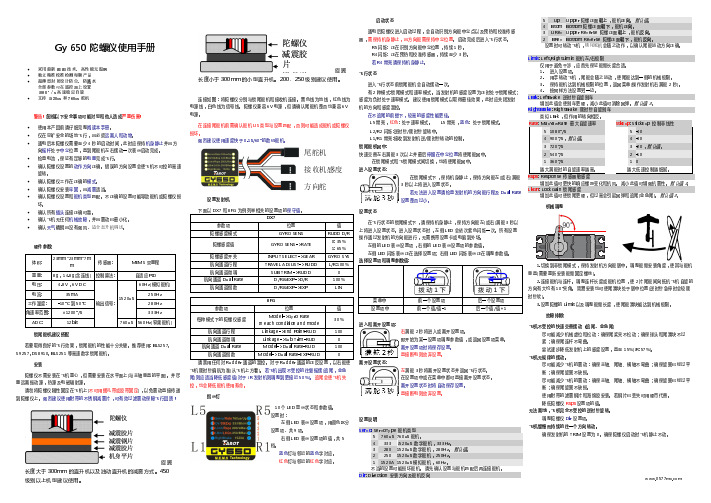
Gy 650 陀螺仪说明书
飞机不受控的快速交替摆动 (追尾、金鱼尾)
尽可能减少机械虚位和松动:确保尾桨夹不松动;确保球头和尾滑块不过 紧;确保尾连杆不弯曲。 尝试逐步降低发射机上的感度设置,直至 15%(JR:57%)。 飞机无规律的摆动。 尽可能减少飞机的震动:确保主轴、尾轴、横轴不弯曲;确保旋翼已经过平 衡;确保尾旋翼不缺损。 尽可能减少飞机的震动:确保主轴、尾轴、横轴不弯曲;确保旋翼已经过平 衡;确保尾旋翼不缺损。 使用附带的滤震钢片和海绵胶安装。若钢片已丢失可用硬币代替。 降低陀螺仪 Rsps 设置项的值。 无法离地,飞机完全不受控的逆时针旋转。 调整陀螺仪 Dir 设置项。 飞机缓慢而持续的往一个方向转动。 确保发射机的 TRIM 设置为 0。确保陀螺仪启动时飞机静止不动。
30%
航向通道行程
Linkage->End Point-RUD
100
航向通道微调
Linkage->Sub Trim-RUD
0
航向通道 Dual Rate
Model->Dual Rate-RUD
100
航向通道指数
Model->Dual Rate-EXP-RUD
0
请禁用任何对 Rudder 通道的混控。对于 Rudder 通道的正反设置,以右舵使
机械调整
1.切换到非锁尾模式,保持发射机方向舵居中。调整舵臂安装角度,使其与舵机 垂直(需要重新安装舵臂固定螺丝)。
2.连接舵机与连杆。调整连杆长度或舵机位置,使 2 片尾舵间向抵抗飞机自旋的 方向有大约有 10°夹角。简易安装也可使尾滑块处于居中位置(逆时针急停时会较顺 时针软)。
3.设置陀螺的 Limit 以及调整舵臂长度,使尾舵滑块能达到机械极限。
左侧的 LED 表示设置项,右侧的 LED 表示设置项的参数值。 左侧 LED 闪烁表示正在选择设置项; 右侧 LED 闪烁表示正在调整参数值。 选择设置项和调整参数值:
G3陀螺仪 说明书
G3 陀螺仪采用全数字化的参数设定方式,避免了因电位器机械磨损所造成的工作不稳 定现象。
【规格】
1. 外形尺寸:26mm*24mm*9mm
2. 重量:12g
3. 工作电压和电流:DC 4.5-6.5V,工作电流≈50mA,最大电流<100mA
4. 适用舵机:模拟舵机(频率 50Hz)、数码舵机(频率 333Hz),舵机中点 1520us
【免责声明】 模型运动本身具有一定的风险,该运动要求玩家具有一定的专业知识和技能。本产品在
设计时已经采取多重安全保护措施,但设备的工作环境和条件差别很大,无法完全预计。我 们强烈建议您尽可能为设备提供良好的安装和运行条件, 确保供电以及控制信号的稳定可 靠, 确认飞行场地的安全。 本公司不承担因使用陀螺仪而造成的直接及间接损失。本产品 一经拆封使用,视同您已认可以上全部条款。
振动陀螺仪安装方法说明书
振动陀螺仪安装方法说明书一、准备工作在开始安装振动陀螺仪之前,请确保您具备以下所需物品:1. 振动陀螺仪设备及其附件;2. 安装支架或架子;3. 所需的工具,如螺丝刀、扳手等。
二、安装步骤1. 确定安装位置在安装振动陀螺仪之前,先要确定其最佳安装位置。
一般来说,振动陀螺仪应安装在稳固的表面上,避免与其他设备存在干扰。
同时,还需要考虑到安装位置是否方便维护和观察读数。
2. 安装支架或架子将振动陀螺仪的支架或架子安装在所选定的位置上。
确保支架或架子稳固可靠,并能够承受振动陀螺仪的重量。
根据实际需要,可以选择固定型支架或可调节角度的架子。
3. 连接附件将陀螺仪设备连接好所需的附件,包括电源线、数据线等。
确保连接牢固,并且线路不会造成其他设备的绊倒或搭乱。
4. 安装振动陀螺仪将振动陀螺仪设备放置在支架或架子上,确保安装牢固。
如果有固定螺丝孔,使用相应的螺丝将振动陀螺仪固定在支架上。
如果是可调节角度的架子,根据需要转动角度和方向,确保振动陀螺仪的感应轴正确对准目标。
5. 调整陀螺仪姿态根据实际需要,调整振动陀螺仪的姿态。
使用各种可调节部件,如支架角度、装置高度等,确保陀螺仪装置与目标设备平行且保持水平。
必要时,可以使用水平仪或其他工具帮助校准。
6. 确保固定稳固在安装完毕后,确保振动陀螺仪设备牢固地固定在支架或架子上。
检查螺丝和连接件是否牢固,避免松动或摇晃。
三、安全注意事项1. 在安装振动陀螺仪时,务必断开电源,以防电击事故发生。
2. 安装过程中避免将脚或手指放置在支架或架子下方,以免造成意外伤害。
3. 在操纵陀螺仪设备时,注意避免强烈冲击和振动,以免影响其工作效果和寿命。
4. 如果发现振动陀螺仪设备存在故障或异常情况,请及时停止使用,并联系专业人员进行检修或维护。
请在按照以上步骤完成振动陀螺仪的安装后,再开启电源,并配置相关软件进行使用。
如有其他问题,请参考设备说明书或咨询技术支持人员。
祝您顺利完成安装,愉快地使用振动陀螺仪!。
HGG05型陀螺仪使用说明书

目次1 概述 (2)1.1 功能及用途 (2)1.2 组成 (2)1.3 主要技术指标及使用环境 (7)2 注意事项 (8)3 操作使用 (8)3.1 对使用人员的要求 (8)3.2 操作前准备 (8)3.3 通电及其检查程序 (9)3.4 调整 (9)3.5 操作程序和方法 (12)4 检测 (13)4.1 仪器常数的标定 (13)4.2 经纬仪(全站仪)检校 (13)4.3 激光对中检校 (13)4.4 仪器精度的测量 (14)5 维护与保养 (15)6 24V直流电池组的充电 (15)7 运输和储存 (16)7.1 运输 (16)7.2 储存 (16)8 标装与标配 (16)11概述1.1功能及用途HGG05型陀螺仪(上置经纬仪或全站仪)是一款全自动、全天候的精密定向仪器,可方便快速实现真北方位角的测量。
仪器操作方便、精度高,可广泛应用于矿山、隧道及井下的定向测量。
1.2组成全套仪器由陀螺仪主机、电控箱、电池、三脚架以及连接电缆、电源线和附件组成。
主机上方架设的经纬仪或全站仪标准配置为南方测绘DT-02L型电子经纬仪或南方测绘NTS960型全站仪。
仪器供电方式可选用220V交流或24V直流,采用24V直流供电时,使用配备的电池及相应的电源线与电控箱连接;采用220V交流供电时,使用相应的电源线直接1.主机2.三脚架3.电源线4.电控箱5.电池6.连接电缆图2 仪器外形图(图中上置为标准配置南方测绘DT-02L型电子经纬仪)1.2.1主机主机由陀螺仪和经纬仪(全站仪)组成,构成见图3。
经纬仪(全站仪)用于照准目标读数;脚螺旋用于架设仪器时调平经纬仪(全站仪)上的水泡;主机上的不锈钢标牌指北标记在仪器初始架设时朝北;底部激光对中器激光点架设时对准测站点;电缆插座用于与电缆线连接。
1.经纬仪(全站仪)2.陀螺仪3.电缆插座4.脚螺旋5.激光对中6.仪器标牌图3 陀螺仪主机1.2.2电控箱电控箱是陀螺仪控制、操作和参数设置的主体,主要由控制电路板、操作按键、液晶显示板等组成。
- 1、下载文档前请自行甄别文档内容的完整性,平台不提供额外的编辑、内容补充、找答案等附加服务。
- 2、"仅部分预览"的文档,不可在线预览部分如存在完整性等问题,可反馈申请退款(可完整预览的文档不适用该条件!)。
- 3、如文档侵犯您的权益,请联系客服反馈,我们会尽快为您处理(人工客服工作时间:9:00-18:30)。
采用了数字的陀螺仪和加速度传感器6轴传感器。这个飞控设置很简单,可调左右平衡增益、前后平衡增益,飞行方向增益这3个电位器。
4个通道输入(1:副翼通道:2:升降通道:3:方向通道:4:飞行方式选择通道)
飞行方式选择通道:
无GPS时三档开关选择:平衡模式、3D模式(可实现稳定的倒飞、吊机)、手控模式
尺寸很小,2.5CM * 4.5CM * 1CM 和一般接收机差不多
4: 支持外接爆闪灯,可以夜空中显示飞机位置。
有GPS时三档开关选择:平衡模式、定高定向模式(由平衡模式切至中间位置)、定高模式(由返航模式切至中间位置)、自动返航模式
摇杆打满对应锁角40度,摇杆松开飞机锁定平飞,而非单纯陀螺增稳。
在平衡模式时,松开控制杆,飞机自动水平飞行。不带姿态系统、仅带陀螺增稳功能的陀螺仪,(功能是保持当前姿态),摇杆松开,还继续保持当前姿态,就会炸机)
3D模式,可以实现各种姿态稳定飞行。
GPS模式下有4种飞行方式:
Байду номын сангаас
1:平衡飞行模式
2:定高定向模式(高度,飞行方向锁定,但目的高度和飞行方向均可以微调,此模式在FPV中非常方便)
3:定高模式(高度锁定,副翼控制参照平衡模式,目的高度可以可以微调)
4:自动返航模式(完全由GPS控制,返回“家”的位置)