浊环水系统功能规格书
浊环水2
钢铁连铸水系统浊环水处理优化方案2010-10-28 10:32作者:江苏明洋环保有限公司一、行业概况冶金行业连铸水系统浊环水除油一直是困扰冶金企业的老大难问题,总在寻求新的有效的处理办法。
含油污水处理难,主要是污水中含有的油份及铁皮、泥砂等杂质,形成具有较大粘性的“油泥”,油泥极易粘附在管道和用水设备上,使管道及用水设备(如喷嘴)堵塞,影响正常生产和产品质量,严重时使车间停产。
油泥粘附在过滤设备的滤料上堵塞滤料不易清除,使过滤设备不能正常运行。
水处理设备运行不正常,又使循环水质继续恶化,致使循环系统处于恶性循环状态,为维持正常生产,有些厂家将含油污水全部或部分外排,严重污染了水体,并浪费了宝贵的水资源。
为此,各生产厂家及设计科研部门均在研究、探索新的除油方法,以改善冶金行业浊环水车间浊环水水质。
在五、六十年代,各冶金行业浊环水一般采用二次沉淀的方法去除水中大部分铁皮,并以隔油方式去除一部分浮油,其处理效果不佳。
七十年代在武钢中引进了带式除油机,并在浊环水处理流程中采用了压力过滤器,长期运转证明,带式除油机虽有一定的除油效果,但只能去除部份浮油,并且要求水流必须经过带式除油机部位。
这一点对处理大水量工程很难办到。
压力过滤器滤料易被油泥堵塞,需经常更换滤料,管理困难。
以后又陆续出现管式除油机,但刮油不彻底,只能去除部分浮油,去除不了乳化油。
气浮法除油效果较好,但动力消耗大,设备复杂,水量大时难以实施。
二、同类行业成功工艺根据江苏明洋环保有限公司对钢铁连铸水系统浊环水系统的长期研究及开发。
结合钢铁连铸水系统浊环水系统中含油量、成份及水中悬浮物的特点。
随着国内冶金行业钢产量的饱和,各钢铁企业对产品的要求都向高端产品发展的同时,对水质要求将越来越高。
江苏明洋环保有限公司优化设计工艺为化学除油器+高速过滤器,将作为高附价值炼钢、连铸水系统的主流工艺。
处理效果:进口水中悬浮物在200mg/l,出水悬浮物含量为<10mg/l。
轧钢厂棒材水处理操作规程
申银特钢轧钢厂规程棒材水处理操作规程2017-6-15发布2017-6-15 实施批准:审核:编制:目录第一章.系统概述及生产工艺流程示意图 (2)第二章.设备及其性能参数 (4)第三章.设备操作 (6)第四章.系统操作 (7)第五章.各种故障及事故处理施 (8)第一章系统概述及生产工艺流程示意图1 系统概述本厂水处理工艺包括:净环水系统、浊环水系统、穿水系统。
主要服务于棒材热送轧钢的正常运行。
水处理主要的建筑及构筑物有:循环水泵房、一次沉淀池、平流池、浊环冷水池、浊环热水池、浊环冷却塔、净环水池、净环冷却塔。
1.1 生产供水系统生产供水系统是从厂区管网给轧钢厂各个储水设施进行补水的供水管路,主要用于加热炉软水站的生水补充(一类水)、净浊环水池的补充(一类水)。
1.2 循环供水系统循环水供水系统包括净环水系统、浊环水系统、穿水系统。
1.2.1 净环水系统净环水系统按照区域划分两部分:A线净环水系统和B线净环水系统。
两套净环水系统共用3台净环水泵,共用同一水池,共用一套净环水冷却塔。
A线净环水系统功能是分别供给A线加热炉软水系统、A线加热炉风机冷却系统、A线加热炉后炉梁和出入炉辊道冷却系统、A线轧机和飞剪电机冷却系统、A线液压系统、A线稀油润滑系统、A线冷床升降裙板拉杆等设备,进行设备的间接冷却降温。
B线净环水系统功能是分别供给B线加热炉软水系统、B线加热炉风机冷却系统、B线加热炉后炉梁和出入炉辊道冷却系统、B线轧机和飞剪电机冷却系统、B线液压系统、B线稀油润滑系统、B线冷床升降裙板拉杆等设备,进行设备的间接冷却降温。
图1.1 A、B线净环水系统流程示意图1.2.2 浊环水系统浊环水系统的功能是向轧钢车间提供浊环冷却水。
供水点有:各轧机轧辊、活套、导卫等。
浊环水系统按照区域划分两部分:A线浊环水系统和B线浊环水系统。
两套浊环水系统共用3台浊环水泵,共用一次沉淀池、平流池、浊环冷水池、浊环热水池,共用一套浊环水冷却塔。
炼钢厂百吨炉区连铸浊环水改造经验谈
炼钢厂百吨炉区连铸浊环水改造经验谈摘要本文介绍了宣钢炼钢厂百吨炉区连铸浊环水系统现状,针对水质不达标影响连铸坯质量问题而对浊环水系统整个工艺流程制定的技术改造方案,以及改造后达到的良好效果。
关键词浊环水;化学除油器;悬浮物1 项目必要性炼钢厂110炉区连铸浊环水系统,由综合泵站连铸浊环水系统冷、热两个泵组共六台水泵完成系统循环。
2007年4#、5#连铸机扩容造后,110t炉区二冷水循环量由原770t/h上升到1 170t/h,再加上渣粒化水400t/h,合计约1 600t/h,均需通过110t炉区的化学除油器处理后进行循环使用。
我厂原110t炉区化学除油间只有4台化学除油器,额定处理能力1 200t/h;因此扩容后所需处理水量已远远超出4台化学除油器的处理能力,致使二冷水的悬浮物在30mg/L,油10 mg/L以上,均不能达到《钢铁工业给排水设计手册》规定标准。
(二冷水悬浮物20~30mg/L、油5mg/L 以下的要求(-941))。
造成二冷喷嘴堵塞几率升高,铸坯冷却不均匀,不但易造成漏钢等生产事故,而且易产生铸坯疏松、缩孔、裂纹等缺陷。
2 项目方案本系统工艺流程:化学除油器出水→泵站热水池→三台热水泵→五台双旋过滤器→冷却塔→冷水池→冷水泵→泵站两级全自动反冲洗过滤器→连铸机单极全自动反冲洗过滤器→连铸机二冷用点→旋流井→化学除油器进水。
根据以上工艺确定具体改造方案如下:2.1对化学除油间的改造1)将化学除油间西南角的4间办公平房拆除,新建化学除油间(24×8×9m),增设2台处理水量:400t/h化学除油器(CYCW-400),共增加处理水量800t/h,与原有4台400t/h化学除油器相加,其中1台化学除油器处于清理检修状态,5台400t/h化学除油器运行,共处理水量2 000t/h。
新增2台化学除油器后,通过检修逐一对原4台化学除油器排污系统由单一排污升级改造四点排污,使其达到应有的处理能力。
RiOs Essential 5, 8, 16, 24水净化系统说明书
A reliable, user-friendly pure water solutionA reliable, user-friendly pure water solutionYour water purification needs Our solution: the RiOs™ Essential range of water purification systemsReliable, constant production of high-quality Type 3 pure water Complementary water purification techniques including pretreatment and high–performance reverse osmosis (RO) membranes enable reliable production of Type 3 pure water. Temperature compensation ensures dependable, constant flow rates.Full control over your water production facility Essential water quality information is shown on the system display, including key water quality parameters measured by the system’s monitoring equipment.RFID technology provides pack traceability.User-friendly operation Intuitive controls simplify RiOs™ Essential system use, providing just the information required.System alert and alarm icons are shown on a color-coded backlit LCD displayto clearly show message importance. Optional Millitrack® software provides data management, archiving and remote access capabilities.A robust, low-maintenance system RiOs™ Essential systems benefit from established RO technology and automatic RO self-maintenance functions. There is just one Progard® pretreatment pack to change on the system, and a new, ergonomic pack locking system lets users do this quickly and easily.Easy installation RiOs™ Essential systems have a small footprint, enabling convenient installation on or under the bench, or on a wall to make the best use of laboratory space.Low running costs The RO water recovery loop increases pretreat-ment pack lifetime, and also decreases water consumption by 50% or more compared to standard RO systems.Confidence in your water purification system supplier EMD Millipore is a partner you can count on. RiOs™ Essential systems are manufactured in an ISO®-registered manufacturing site, and Watercare Pact service plans offer a full range of support.2RiOs™ Essential systems10. Reject Water Recovery Loop 11. Capillary Tubing 16. Product Water17. ReservoirReliable, constant production of high-quality Type 3 pure waterRiOs™ Essential water purification systems are ideal for the production of laboratory-grade water, which is particularly suitable for use in glassware rinsing, hydroponics, water baths, and as feed water for humidifiers, autoclaves, glassware washers, washing ma-chines, and Milli-Q® ultrapure water systems.By filtration through a Reverse Osmosis (RO) membrane, RiOs™ Essential systems ensure the removal of all contaminants initially present in potable water. The semi-permeable RO membrane is protected from clogging by a Progard® pretreatment pack, which contains a combination of three purification media.The water produced is always of optimal quality; each time the system is restarted, water is rejected until its quality meets the required expectations.32 – Advanced reverse osmosisAdvanced reverse osmosis is a particularly effective technique for obtaining good water purity, removing 95-99% of inorganic ions and 99% of all dissolved organic substances (MW > 200 Dalton), in addition to microorganisms and particles.RiOs™ Essential systems incorporate two advanced features that provide major benefits for users:④ Reduced water waste is achieved by recycling part of the reject water to the ROmembrane feed water stream, which decreases water consumption by 50% or more compared to standard RO systems.④ Constant product flow rate is achieved through the use of a unique temperaturecontrol feature in the built-in booster pump. Standard reverse osmosis–based systems suffer from a decline in product flow rate as water temperature decreases. Unlike these o ther systems, RiOs™ Essential systems benefit from temperature compensation, which ensures a dependable and constant flow rate. As temperature decreases, RiOs™ Essential system pump pressure increases to maintain a steady production rate, ensuring that pure water is always available when you need it, and enabling the system to adapt to a wide range of feed water types.EMD Millipore’s robust RiOs™ Essential systems have been developed to ensure reliable, constant production of high-quality Type 3 pure water. These robust systems incorporate complementary water puri-fication techniques including pretreatment and high–performance reverse osmosis membranes.1 – Pretreatment protects the systemIn the RiOs™ Essential system water purification sequence, potable tap water is first treated with a Progard® pretreatment pack. This first pu-rification step protects against:④ Particles (1 µm filter)④ Free chlorine and colloids from the tap water (activated carbon)④ Hardness, via an anti-scaling agent that protects the reverse osmosis membraneThe RiOs™ Essential system step by stepFigure 1. Flow-through view of a RiOs™ Essential system RO membrane, which is inserted into a cartridge. Tangential flow limits the risk of fouling; the membrane removes 95-99% of inorganics and 99% of all dissolved organic substances with greater than 200 Dalton, such asmicroorganisms and particles.4Full control over your water production facilityEssential water quality information is shown on the system’s easy-to-read backlit LCD display, including the key water quality parameters that are measured by the system’s mon-itoring equipment (product water resistivity/conductivity compensated to 25 °C and tank level).To enable optimized control of water quality and self-maintenance functions, RiOs™ Essential systems check important relevant parameters:④ Feed water pressure, feed water quality, feed water temperature④ RO pressure, RO water quality and RO membrane efficiency (% rejection of ions), ROwater temperatureRFID technology provides further control by preventing insertion of an incorrect purification cartridge in the RiOs™ Essential system, and also by ensuring traceability of pack use and replacement.When your RiOs™ Essential system will not be used for a long time, the “Lab Closed” function lets you maintain water quality by periodic automatic flushing and rinsing.RiOs™ Essential systems have been designed for easy, effortless operation. Intuitive controls on the system cabinet simplify use, and provide essential details — you see just the information you need. When necessary, icons inform users of any actions that should be performed, such as routine maintenance reminders (i.e., changing the Progard® pack, sanitizing the system), or taking corrective measures in case of an alert or alarm.To ensure optimal system operation, icons and the backlit LCD screen change color to visually signal maintenance alerts or alarms. For example, fifteen days before the purification pack should be replaced, the Progard® icon will turn yellow. As the date for pack change approaches, the LCD screen will switch from its normal blue background color to yellow. For more important warnings, the screen will turn red to indicate an urgent action is required. When there has been no user in-teraction with the screen for 15 minutes, and there is no alert or alarm, the system’s “ECO” mode screen saver will be activated automatically.For even greater flexibility, optional Millitrack® software is available for system users who would like to benefit from enhanced data management control, remote access capabilities and long-term electronic archiving provided by an interactive web interface.Additional information on system operation and maintenance is provided by the Quick Reference Guide and User Manual stored on the water production unit.User-friendly operation5A complete range of RiOs™ Essential systems and specially designed storage reservoirs are available to meet the needs of laboratories requiring anywhere from 30 to 480 L of pure water per day. With their small footprint, RiOs™ Essential systems are designed to make the best use of laboratory space. Systems can be placed on or under the bench or wall-moun-ted, depending on your needs. Larger installations, based on the same principle, are also available for users with needs up to 8000 liters per day.Select from a range of high quality polyethylene re-servoirs (30-100 liters) to match your water usage. For storage of larger volumes of water, 200 L and 350 L SDS (Storage & Distribution System) reservoirs are also available.Easy installationRiOs™ Essential systems integrate established advanced RO technology and automatic RO self-maintenance functions. The systems are robust and require little maintenance, leaving you free to concentrate on your laboratory work. Clear instructions, alerts and alarms make it easy to keep your system in optimum condition.There is just one Progard® purification pack to change — and the system’s new ergonomic pack locking system makes this easier than ever to do. Just pull up on the locking handle to remove the exhausted pack, position the replacement pack in the cabinet, and push down on the handle to lock the new pack in place — it’s as simple as that! This is followed by an automatic 15-minute flush cycle, and your system is once again ready for use.Automatic self-maintenance functions (e.g., flush mode, rinsing mode, sanitization cycle) keep the system’s reverse osmosis mem-brane in top operating condition, and ensure optimal water quality. System sanitization is recommended approximately four times a year, and takes just a few minutes to perform.A robust, low-maintenance system6Budget-conscious users will also appreciate RiOs™ Essential systems for their low running costs:④ Only a single Progard® pretreatment pack is needed to remove particles, free chlorine and colloids from tap water.④ Compared to standard RO systems, the RiOs™ Essential system’s efficient RO-reject water recirculation loop decreases tap water consumption by 50% or more, and also doubles the lifetime of the Progard® pack, as the recovered water has already been pretreated.④ The entire pretreatment sequence, as well as the self-maintenance functions and cleaning cycles for the reverse osmosis membrane, ensure optimum final water quality. Consequently, the RO membrane lifetime is extended, which results in decreased running costs.Low running costsAs one of the top three R &D investors in the Life Science Tools industry and with more than 50 years of experience in water purifi-cation systems manufacturing, EMD Millipore is a partner you can count on.RiOs™ Essential systems are manufactured in an ISO® 9001 v. 2008 and ISO® 14001-v. 2004-registered manufacturing site,* and are certified for safety and electro-magnetic compatibility (CE, cUL, FCC).Additionally, to optimize the performance and lifetime of your water purification system, EMD Millipore offers a complete portfolio of Watercare Pact Service Plans ranging from a single annual checkup to a full system cover.Confidence in your water purification system supplierTap WaterDrainFigure 2 Advanced RO technology with high water recovery reduces water consumption by 50% or more. Some of the rejected water is recycled to the RO membrane feed downstream of the Progard® cartridge, making EMD Millipore RO systems best-in-class in terms of economical and environmental impacts.* Certificates are available upon request.7RiOs™ Essential system specifications* If the Fouling index is ≥ 12, additional pre-filtration is recommended.For more information, please visit our website:/labwaterEMD Millipore, the M mark ,Progard, Milli-Q and Millitrack are registered trademarks of Merck KGaA, Darmstadt, Germany. RiOs is trademark of Merck KGaA. ISO is a trademark of the International Organization for Standardization.Lit. No. PB4882ENUS© 2014 EMD Millipore Corporation, Billerica, MA, U.S.A. All rights reserved.。
转炉浊环水处理资料-经过多年改进-经验

运行控制: ⑴手动控制:根据运行状态进行手动排泥,设在排泥管道上的电动阀门由 机旁电控箱手动控制。运行情况可在浊环泵站的计算机画面上显示 。 ⑵自动控制:根据设定好的程序和时间依次运行,运行情况可在浊环泵站 的计算机画面上显示 。
斜板沉淀器平面示意图
3.带式压滤机
DYT—2000 型带式压滤机8台,处理泥量15立方米/ 小时。泥饼含水率30%左 右。采用聚酯或尼龙滤带。 主传动部分采用无级变频调速电机及双排套筒磙子链传动,每台压滤机配一套机 旁操作箱及变频调速控制柜。 正常状态下6—7台工作,一台备用。
炼钢浊环水处理系统简介
一.浊环水处理系统的作用
是将转炉除尘系统循环水中吸附的高浓度(约20000mg/L) 悬浮物通过一系列设备加以分离,分离后的水(悬浮物浓度按设 计应小于50mg/L)再输送到除尘系统循环利用。分离出的悬浮 物最后经压滤机制成泥饼(主要成分为氧化铁)送炼铁做原料。
二.浊环水处理系统的工艺流程
粗颗粒机剖面示意图
来水
出 水 送 至 斜 板
排 泥 装 置 排 泥
2.斜板沉淀器
是处理浊环水的主要设备,经过粗颗粒分离间初步处理后的转炉污水 经两条DN800的钢管自流至斜板沉淀器。经两条主流槽分配到各斜板 沉淀器,经沉淀器净化后的污水利用高差架空送至浊环泵站热水池。 其中1#---6# 送浊环泵站2#热水池,对应2#转炉。7#---12# 送 到3#热水池,对应3#转炉。 13#---18#送到1# 热水池,对应1# 转炉。沉淀器下部沉淀的泥浆由螺旋输泥机排出,用气力输送方式送 到粗颗粒分离间内的三个泥浆池中,再用渣浆泵送到压滤间经带式压 滤机处理。 主要设备: LS-48型斜板沉淀器18台,沉淀器单台设计水量130m3/h 。
轧钢厂棒材水处理操作规程精编版

轧钢厂棒材水处理操作规程精编版MQS system office room 【MQS16H-TTMS2A-MQSS8Q8-MQSH16898】申银特钢轧钢厂规程棒材水处理操作规程2017-6-15发布 2017-6-15 实施批准:审核:编制:目录第一章.系统概述及生产工艺流程示意图 (2)第二章.设备及其性能参数 (4)第三章.设备操作 (6)第四章.系统操作 (7)第五章.各种故障及事故处理施 (8)第一章系统概述及生产工艺流程示意图1 系统概述本厂水处理工艺包括:净环水系统、浊环水系统、穿水系统。
主要服务于棒材热送轧钢的正常运行。
水处理主要的建筑及构筑物有:循环水泵房、一次沉淀池、平流池、浊环冷水池、浊环热水池、浊环冷却塔、净环水池、净环冷却塔。
1.1 生产供水系统生产供水系统是从厂区管网给轧钢厂各个储水设施进行补水的供水管路,主要用于加热炉软水站的生水补充(一类水)、净浊环水池的补充(一类水)。
1.2 循环供水系统循环水供水系统包括净环水系统、浊环水系统、穿水系统。
1.2.1 净环水系统净环水系统按照区域划分两部分:A线净环水系统和B线净环水系统。
两套净环水系统共用3台净环水泵,共用同一水池,共用一套净环水冷却塔。
A线净环水系统功能是分别供给A线加热炉软水系统、A线加热炉风机冷却系统、A线加热炉后炉梁和出入炉辊道冷却系统、A线轧机和飞剪电机冷却系统、A线液压系统、A线稀油润滑系统、A线冷床升降裙板拉杆等设备,进行设备的间接冷却降温。
B线净环水系统功能是分别供给B线加热炉软水系统、B线加热炉风机冷却系统、B线加热炉后炉梁和出入炉辊道冷却系统、B线轧机和飞剪电机冷却系统、B线液压系统、B线稀油润滑系统、B线冷床升降裙板拉杆等设备,进行设备的间接冷却降温。
图 A 、B 线净环水系统流程示意图1.2.2 浊环水系统浊环水系统的功能是向轧钢车间提供浊环冷却水。
供水点有:各轧机轧辊、活套、导卫等。
浊环水系统按照区域划分两部分:A 线浊环水系统和B 线浊环水系统。
棒材厂-轧浊环水系统改进
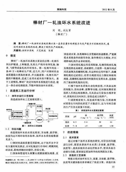
浊环 水系统 经 过 6个 月 的运 行 基 本 正 常 , 其 尤
是在 主线 满负 荷生 产 的时候 , 质 均 达到 了设 计 目 水
的和生产 要求 。 3 2 环 境 改善 .
一
2 化学 除 油器是 以投 加 化学 药 剂 , 混 合 反 应 ) 经 使水 中的油类 、 氧化 铁皮 等悬 浮物 通过 凝 聚 、 絮凝 作
动 清污 功能 , 需要 制定 更加 科学 的药 剂投加 方案 。
2 2 改造后 工艺 流程 .
2 泵体 和 管道 弯头 频 繁 出现磨 损腐 蚀 现 象 , ) 直
作者简介 : 刘 明(9 4一), ,0 8年 7月毕业于青岛理工 大学机 18 男 20
根 据主 线对 浊环 水压力 、 量 、 油量 、 流 含 悬浮 物 、
种模 式下 , 决定 了泵 的控 制是 就地 或是 远程 。
2 西 门 子 C U 模 板 故 障 诊 断 。该 系 统 使 用 ) P
O3 B 5组织 块 , 周期循 环 执行 , 保 C U 内保 存 的 状 确 P
态信 息得 到及 时准 确地 反馈 。使 用一 台上位 机与 多
个 P C同 时通 讯 , L 一个 项 目同 时监控 现 场所 有 P C L
改 进后 浊环 水水 质检测 情况 见表 2 。
表 2 改 进 后 浊 环 水 水 质 测 定 数 据
1通过 现场实 际考察 确定 , 一级提 水泵 由 ) 将
30 B—B 1 台 ( 用一 备 ) 换 为 40 B— 5 WF D 三 两 更 0 WF B 2两 台 ( 用一 备 ) 这样 减 少 了 一级 提 水 泵 的运 D 一 , 行 数量 , 日常 的点检 维护将 更方 便快 捷 , 泵供 水能 该
300S58A浊环泵安装使用说明书
300S58A浊环泵安装使用说明书成都宝林伦机械制造有限公司二○○五年三月十八日目录一、概述与结构说明 (1)二、300S58A浊环泵的装配 (3)三、泵的安装 (4)四、输送管 (5)五、起动、停止与运转 (5)六、可能发生故障及其解决方法 (7)七、泵外形及安装尺寸 (8)一、概述与结构说明1.300S58A型浊环泵用于钢铁厂高炉冷却水输送,温度约80℃,含有5%的炉渣颗粒。
2.水泵型号意义:300S58A300——吸水管口径S———单级双吸水平中开卧式泵58———泵的最大杨程A———叶轮经过一次切割3.300S58A型浊环泵主要技术规范杨程:50米流量:720米3/小时功率:轴功率:116kw配用电机:160kw转速:1450转/分效率:83%汽蚀余量:5m叶轮直径:410mm重量:900公斤4.结构说明300S58A型浊环泵为单级双吸水平中开卧式水泵。
泵的吸入管及吐出管均在泵轴中心线下方成水平方向,与轴线成垂直位置。
泵体泵盖的分开面在轴心线上,成水平方向,可以便于揭开检查水泵内全部零件,无需拆卸吸入、吐出管路及原动机。
因此检修极为方便。
从传动方向看出,泵为顺时针方向旋转。
泵用滚动轴承支承于两端的轴承座上,滚动轴承为SKF6312。
300S58A型浊环泵的主要零件是泵体①,泵盖②,叶轮③,轴④,轴承部件⑤,密封部件⑥。
泵体①,泵盖②,是CuCrMo合金铸铁制成,共同构成泵的工作室,吸入管及吐出管在它的下方与泵体铸成一体,在吸入管及吐出管的法兰盘上有安装真空表及压力表的管牙孔。
叶轮③是NiCrMo合成铸铁制成,液体从两面进入叶轮,由于叶轮形状是对称的,因此叶轮两侧所受的压力相等,泵在理论上是没有轴向推力的。
轴④为45优质碳素钢制成,经调质处理和超声波探伤检查。
叶轮装在轴的中间,用平键及轴套背帽固定,轴套一方面固定叶轮位置,另一方面保护轴并防止介质中的颗粒和填料对轴的磨损。
轴套材料为2Cr13不锈钢经调质处理。
炼钢转炉浊环水系统工程高速过滤器技术协议

炼钢转炉浊环水系统工程高速过滤器技术协议山东百科环境工程有限公司2017年12月技术协议甲方:乙方:双方经公平、友好协商,就炼钢转炉浊环水系统改造工程达成一致,协议如下:一、技术要求1、高速过滤器的处理对象主要是循环水中的机械杂质、胶体、微生物、有机物、油等,其处理的好坏直接影响循环水工艺的技术经济效果和长期安全运行。
过滤器工作状态为压力式,滤料采用双层滤料,石英砂及无烟煤。
2、主要技术参数3、供货范围过滤器 3台(不含滤料)平台爬梯 1套4、高速过滤器平台、爬梯要求4、1乙方需要提供3台过滤器的顶部检修平台,平台间连接通道和上平台的钢制爬梯。
4、2顶部检修平台为带表面喷涂处理的钢制格栅平台,支撑在过滤器本体上。
该平台布置在过滤器顶部,平面尺寸不小于2000×2000mm,平台荷载按照250kg/m2考虑。
4、3平台间连通走道宽度不小于1m,顶部平台及连通走道的两侧配有安全栏杆扶手及100mm高踢脚板。
4、4为方便检修,顶部平台一侧的栏杆为活动栏杆。
钢制爬梯用于从过滤器中间检修上至顶部检修平台。
5、乙方应事先进行现场踏勘,因3台过滤器的基础已经竣工,乙方应按甲方现有的设备基础及甲方提出的设备参数要求自行设计开发进行生产制造,半成品运至甲方施工现场进行焊接安装,乙方负责过滤器填料的装填,向甲方提供过滤器填料装填级配及装填高度,规格缺失的填料乙方负责补充。
5、1 乙方根据甲方主机要求,进行设计开发的配套件应充分满足和达到甲方所提出的各项技术性能、参数指标和质量要求。
5、2乙方开发设计的技术图样应送交甲方会签,经甲方会签确认后方可进行生产制造。
5、3 本协议签订后,经甲方会签确认的设计图样或其他技术文件作为本协议的附件与本协议一并生效,两者缺一,视为无效。
二、资料交付1、图纸资料应包括过滤器的总装图、管口方位图。
总装图应示意出过滤器的内部结构。
2、乙方应在合同签订后7天内将设备安装图等相关资料交付给甲方。
TSS浊度计技术资料
TSS浊度计(Turbidity Analyzer)产品描述TSS浊度计是为测量市政污水或工业废水处理过程中水的浊度而设计的在线分析仪表。
TSS浊度计由变送器和传感器组成。
传感器可以很方便地安装在池内或自然水体中。
TSS浊度计能自动补偿因污染而引起的干扰。
变送器和传感器之间的双向数字通讯可防止信号衰减,并允许传感器距离变送器之间的距离较远。
应用领域 水及污水处理进水口、出水口、中水处理等 造纸、电力、矿山水处理等工作原理TSS浊度计的工作原理如图1-1所示,传感器上发射器发送的红外光在传输过程中经过被测物的吸收、反射和散射后,有一部分透射光线能照射到180°方向的检测器上,有一部分散射光照射到90°方向的检测器上。
在180°和90°方向检测器上接收到的光线强度与被测污水的浊度有一定的关系,因此通过测量透射光和散射光的强度就可以计算出污水的浊度。
通过测量两个检测器上光的强度,可以实现自动补偿,有效消除干扰,补偿因污染产生的偏差,使仪器能在较恶劣的环境中工作。
图1 TSS浊度计的工作原理图性能特点 标准90度散射光测量技术,提供可靠测量结果; 自动补偿电压波动、器件老化、温度变化以及污泥颜色的变化; 超声波自清洗功能,基本免维护; 中文菜单和简便的按键操作; 具有气泡消除系统; 浸没式、流通式等多种安装方式,适合各种应用场合; 双通道输入,即插即用; 故障自诊断功能;仪表接线1.变送器安装尺寸 发射器检测器图2 变送器正视图 图3 变送器侧视图图4 变送器背板图2.变送器安装方式变送器背后有三个孔,尺寸如图4所示,其中上面的孔用于悬挂,下面两个孔用于加螺栓固定。
图5 遮阳罩图6 仪表保温箱3.传感器的安装图7 传感器尺寸浸没式安装方式是指把传感器通过安装支架浸入池中或罐中的安装方式。
图8 浊度计安装示意图(1)、首先在安装传感器的池壁合适位置打入四个M10钢制膨胀螺栓,将如图9所示的传感器池壁安装支架通过M10螺母和弹簧垫片固定在池壁的螺栓上,安装完成后如图9中右图所示。
浊环水系统功能规格书
路漫漫其修远兮,吾将上下而求索-百度文库芜湖新兴三山工业区高线水系统工程浊环水处理系统功能规格书河北新烨工程技术有限公司2011、12浊环水处理系统功能规格书本浊环水处理系统分为浊环水处理站和过滤间两部分,浊环水处理站处理两条高速线材及一条小棒生产线的浊环水,并预留处理能力为1500m³/h 稀土磁盘位置,浊环水处理能力7500m³/h,预留处理能力1500m³/h;过滤间主要处理两条高速线材需过滤的浊环水,浊环水最大过滤水量1120m³/h,预留场地给小棒生产线及扩产所需的过滤浊环水过滤。
1.工艺概述经旋流井处理后的浊环水用泵送入稀土磁盘,经稀土磁盘处理后的净化水自流入平流池再流至吸水井,浊环提升泵站设提升泵,部分水提升至高速过滤器净化后回联合泵站冷却塔,冷却塔出水自流至联合泵站循环水池,由联合泵站的供水泵循环使用;另一部分直接回联合泵站冷却塔,冷却塔出水自流至联合泵站循环水池,由联合泵站的供水泵循环使用。
稀土磁盘出渣接至磁力压榨机,压榨后得干渣和滤液,干渣排入渣池由抓斗装车外运;滤液排至滤液池后用潜污泵送回至旋流井。
2.浊环水处理站浊环水处理站分为渣池跨、稀土磁盘工作平台跨、浊环水提升泵站和药剂库及备件库。
浊环水处理站渣池跨设3个4.8X10X2m渣池和3个2.7X10X3m滤液池,滤液池顶设5台两辊磁力压榨脱水机,各滤液池内设1台潜污泵,渣池上设1台抓斗吊钩两用桥式起重机用于抓渣。
滤液池设有液位测量在联合泵站控制室显示,液位高于1.6m控制室内报警。
稀土磁盘工作平台跨设有3个10X16.5X5m平流池,平流池内设配水花墙、导流墙和3台圆盘除油机;平流池上4m工作平台2组SMDD-1500X2和1台SMDD-1500稀土磁盘,设3台轴流风机和1台检修用悬挂式电动单梁起重机。
浊环水提升泵站设30X12X5m吸水井,吸水井上设3台过滤浊环水提升泵、3台水冷浊环水提升泵、3台普通浊环水提升泵、3台轴流风机和1台检修用悬挂式电动单梁起重机,水泵均为2用1备;吸水井设有液位测量在联合泵站控制室显示,液位高于3.4m报警、液位低于0.3m报警、液位低于±0.00浊环水提升泵站内所有水泵停泵。
电厂循环排污水处理回用系统技术规格书
电厂循环排污水处理回用系统技术规格书1. 系统概述该循环排污水处理回用系统是为电厂排放生产废水进行处理并实现回用的设备。
系统采用先进的处理技术,能够高效地去除废水中的污染物,并经过处理后可被循环利用,降低水资源浪费。
2. 技术规格2.1 处理能力•日处理废水量:XXX立方米•处理效率:XX%•回用水质:符合XXXX标准2.2 处理工艺•膜分离技术:采用XXX型膜组件•氧化技术:采用XXX氧化剂•混凝沉淀技术:采用XXX混凝剂2.3 设备参数•主处理设备型号:XXX•设备材质:不锈钢•设备尺寸:根据现场实际情况设计3. 系统组成3.1 进水系统•进水泵:XXX型号•进水管道:材质为XXX•进水流量计:XXX型号3.2 处理系统•膜分离设备:XXX型号•氧化设备:XXX型号•混凝沉淀装置:XXX型号3.3 出水系统•出水管道:材质为XXX•出水流量计:XXX型号•出水泵:XXX型号4. 控制系统•主控制面板:XXX型号•PLC控制器:XXX型号•人机界面:触摸屏显示5. 运行参数要求•进水温度范围:X℃-X℃•PH值范围:X-X•操作压力范围:X-X MPa6. 安全保障•系统应设有过载保护功能•设备操作应符合相关安全操作规程•定期进行设备检查与维护7. 维护保养•每季度对设备进行一次全面检查•定期清洗和更换滤芯、膜组件等易损耗部件•系统异常时立即停机并进行故障排除以上为电厂循环排污水处理回用系统的技术规格书,以上规格可根据实际情况进行调整和优化。
MilliporeSigma RiOs 3, 5, 8 实验室级水净化系统说明书
RiOs™ 3, 5, 8Water Purification Systems Reliable and affordable pure water solutionsThe life science businessof Merck operates asMilliporeSigma in theU.S. and Canada.Reliable and affordable pure water solutionsReliable, affordable laboratory grade water Our RiOs™ systems produce reliable, affordable Type III pure water for a variety of laboratory applications, thanks to high performance reverse osmosis (RO) membranes.Pure water for general laboratory use RiOs™ system pure water is suitable for a variety of needs, including manual cleaning and rinsing, and buffer and reagent preparation.Pure water to feed ultrapure water purification systems or otherlab equipment Water from RiOs™ systems can also be used as feed water for ultrapure water systems (e.g., Synergy® systems), as well as feed to humidifiers, autoclaves, and glassware washers.Flow rates adapted to your daily usage Systems in the RiOs™ range provide 3, 5, or 8 liters of pure water per hour.A choice of adequate storage volumes RiOs™ systems come either with an integrated 6-liter reservoir (RiOs™ 3) or an external reservoir (30 L or 60 L).Compact design for the most efficient use of your lab space A small footprint makes it easy to install the RiOs™ water purification units wherever you want in your lab.Easily accessible information on system operation The user-friendly display provides system status at a glance; the concise Quick Reference Guide is a handy guide for daily operation.®Benefit from compact,user-friendly design Optimized lab spaceWith their small footprint and robust design, RiOs™ waterpurification units can be installed wherever you need pure water in your lab, on the benchtop, or on the wall.** R iOs™ 5 and RiOs™ 8 systems are designed for use with a 30 L or60 L external reservoir.Choose the pure water solution that’s right for you Reliable, affordable pure waterDesigned to produce reliable, affordable pure water, RiOs™ systems are a perfect solution for Type III laboratory-grade water needs. Select the RiOs™ system that best matches your daily water volume needs: the range includes models that produce 3,5 or 8 liters of pure water per hour. Pure water is stored conveniently either in an integrated 6-liter reservoir for the RiOs™ 3 system, or in external 30 L or60 L reservoirs for the RiOs™ 5 and RiOs™ 8 models.Feed water for ultrapure water systems and other lab equipmentRiOs™ systems provide an ideal source of pure waterfor use as feed to ultrapure water purification systems, such as our Synergy ®systems. A mere 80-centimeter(32-inch) space suffices to hold the two systems,and you’ll have access to both Type III and Type I (18.2 MΩ·cm) water on demand! When connected to an external reservoir, RiOs™ systems can also supply pure water to feed other laboratory equipment, including humidifiers, autoclaves, and glassware washers.Pure water for general, non-criticallab applications Type III water from RiOs™ systems is suitable for all yourmanual cleaning and rinsing needs, as well as for bufferand reagent preparation; and for use in water baths.Merck offersmore than waterEasy installationRiOs™ systems are designed for easy installation: just connect the system to a tap water supply, plug it in, and insert the SmartPak® RO cartridge. If your configuration includes a 30- or 60-liter reservoir, follow the simple setup procedures, and your system will be ready to use! Just openthe tank outlet valve to dispense pure water ― the integrated 6 L reservoir or external 30/60 L reservoirs store your RO water in optimal condition ready for use when you need it.Just the information you needThe intuitive color graphic display shows key system parameters at a glance, enabling easy water quality and maintenance warning monitoring. Additional information on system operation and maintenance is provided by the Quick Reference Guide and User Manual stored on the water production unit.User-friendly maintenanceThe single SmartPak® purification cartridge with integrated RO membrane protection simplifies maintenance to a quick pack change. You will receive an automatic notification on the RiOs™ system when it’s time to change the cartridge, which is easily done in a couple of minutes.Milli-Q® Services PlansTo optimize the performance and lifetime of your water purification system, we offer a complete portfolio of service plans, ranging from a single annual checkup to full system coverage. For more information, please check with your Merck appli-cations specialist or visit our website: /Milli-QServicesMerck KGaAFrankfurter Strasse 25064293 Darmstadt, Germany /labwater。
洁净水系统用户指南:Commander 篮滤器说明书

Commander™ Cartridge Filter Operating Procedures1620 Hawkins Ave., Sanford, NC 27330 • (919)774-415110951 West Los Angeles Ave., Moorpark, CA 93021 • (805) 523-24003.Provide sufficient space above the filter to remove the filter lid and cartridge for cleaning andservicing. This distance will vary with the model of filter you are using. See Table 1 for the required vertical clearance above the filter.6.THE FILTER BASE IS ABS MATERIAL. WHEN PVC PIPE IS BEING USED THE CORRECT ABSTO PVC SOLVENT PIPE CEMENT MUST BE USED. WE RECOMMEND WELD-ON #793 OR EQUIVALENT.7.An additional inlet port is provided in the base for easier installation. Select the desired inlet portand plug the other inlet port with 1½ in. plug provided, (item #13).a.If your filter has slip ports use item 13, 1½ in. ABS slip plug. Use ABS to ABS solvent, werecommend WELD-ON #771 or equivalent. A ½ in. plug (item #14) is also provided for use asa drain plug.b.If your filter has threaded ports use item 13, 1½ in. threaded plug. Use only teflon tape, 100%teflon paste, or Permatex #2 to seal the threads. Use of other materials could damage theequipment.8.The 25, and 50 sq. ft. models are equipped with Turbo-Flo by-pass valve. If by-pass is not desired,plug off with item #16 using WELD-ON #771 or equivalent.9.The maximum working pressure of this filter is 50 p.s.i. Never subject this filter to pressure inexcess of this amount, even when conducting hydrostatic pressure tests. Pressures above 50 p.s.i.can cause the lid to be blown off, which can result in severe injury, death or property damage.When performing hydrostatic pressure tests or when testing for external leaks of the com-pleted filtration and plumbing system, insure that the Maximum Pressure that the filtrationsystem will be subjected to DOES NOT EXCEED THE MAXIMUM WORKING PRESSURE OF ANY OF THE COMPONENTS CONTAINED WITHIN THE SYSTEM. In most cases, themaximum pressure will be stated on each component of the system.If doubt exists as to the pressure to which the system will be subjected, install an ASMEapproved automatic Pressure Relief or Pressure Regulator in the circulation system for thelowest working pressure of any of the components in the system.SECTION II.FILTER OPERATIONA.GENERAL I NFORMATION1.This filter operates under pressure. When assembled properly and operated without air in the water system, this filter will operate in a safe manner.2.The maximum working pressure of this filter is 50 p.s.i. Never subject this filter to pressure inexcess of this amount - even when conducting hydrostatic pressure tests. Pressures above 50p.s.i. can cause the lid to be blown off, which can result in severe injury, death or property damage.When performing hydrostatic pressure tests or when testing for external leaks of thecompleted filtration and plumbing system, insure that the Maximum Pressure that the filtration system will be subjected to DOES NOT EXCEED THE MAXIMUM WORKING PRESSURE OF ANY OF THE COMPONENTS CONTAINED WITHIN THE SYSTEM. In most cases, themaximum pressure will be stated on each component of the system.If doubt exists as to the pressure to which the system will be subjected, install an ASMEapproved automatic Pressure Relief or Pressure Regulator in the circulation system for thelowest working pressure of any of the components in the system.3.The pressure gauge is the primary indicator of how the filter is operating. Maintain your pressuregauge in good working order.4.Clean your filter when pressure reads between 8-10 p.s.i. higher than the original starting pressure.Your filter pressure reading will increase as it removes dirt from your pool. However, this buildup of pressure will vary due to different bathing loads, temperature, weather conditions, etc.a.MY ORIGINAL STARTING PRESSURE IS ___________ p.s.i. (pounds per square inch). I SHOULD CLEAN THE FILTER CARTRIDGES AT __________ p.s.i.NOTEWhenever the cartridge filter is being used for the first time on a new swimming pool, or when extra water clarity is desired, introduce into the system a one (1) pound coffee can (½ pound of diatomaceous earth) for every 100 square feet of filter area. Mix the diatomite with water and pour it into the skimmer after the pump is primed and the system is operating.B.FILTER L ID I NSTALLATION I NSTRUCTIONS.1.Ensure that the O-ring is in position in the lid then locate lid on rod, centering lid in cartridge opening.2.Secure the entire assembly by using the top knob to firmly seal the lid against the O-ring and the body.3.Before starting pump open the High Flow Manual Air Relief Valve on the filter lid.4.Stand clear of the filter tank, then start the pump.5.Close the High Flow Manual Air Relief Valve when a steady stream of water is flowing. Thisindicates that all air is bled from tank.C.SYSTEM R ESTART I NSTRUCTIONS1.Open the High Flow Air Relief Valve until it snaps into the full open position (this only requires a quarter turn counterclockwise ). Opening this valve rapidly releases air trapped in the filter.2.Stand clear of the filter tank, then start the pump.3.Close the High Flow Air Relief Valve after a steady stream of water appears.4.The system is not working properly if either of the following conditions occur.a.A solid stream of water does not appear within 30 seconds, after the pump's inlet basket fills with water.b.The pressure gauge indicates pressure before water outflow appears.If either condition exists, shut off the pump immediately , open valves in the water return line to relieve pressure, and clean the High Flow Manual Air Relief Valve, see Section F, Cleaning the High Flow Air Relief Valve. If the problem persists, call 1-800-831-7133 for assistance.D.CLEANING F ILTER M ANUALLY1.Turn the pump off, shut off any automatic controls to ensure that the system is not inadvertentlystarted during servicing.2.Open the filter High Flow Air Relief Valve (and, the waste drain valve, or plug, if your system hasone).3.Remove hair and lint strainer pot lid and clean basket. Replace basket and secure lid. Array4.Unscrew large center knob (item 1) and remove top lid assembly (item 4).5.Remove drain plug in base of the filter (item 11) to allow excess water and residue to drain from thetank.6.Remove cartridge or cartridges.ing a garden hose without a nozzle, direct water spray at cartridges to dislodge and wash awayaccumulated foreign matter. Flush each cartridge inside-out.NOTESpecial care must be taken when cleaning filter cartridges used in a swimming pool or spa using Baquacil as a sanitizer. Because of the way Baquacil works, the filter element must be cleanedmore thoroughly and more frequently than in a chlorine system, If extreme care is not taken tocompletely remove all residue from the filter media a buildup will occur. This buildup will signifi-cantly shorten the life of the filter element.Baquacil is a mild coagulant which combines bacterial cells as well as other small particlescontributed by the environment, bathers, etc. into particles large enough to be trapped by thefilter. In comparison with all other trapped contaminants in a typical pool or spa the amount ofbacterial cells that are deposited on the filter is minimal. The resulting deposit is a gray sticky film which can only be removed with Baqua Clean. If TSP or any TSP type cleaner is used prior tostripping the film, the cleaner and the fray film will combine to form a gum-like substance. Oncethis occurs, the substance cannot be removed from the media and the filter cartridge must bereplaced.8.Direct water spray to wash out the inside of the tank body. Water and debris will drain out throughthe open drain port.9.Place cartridge or cartridges into the tank and press firmly into filter base. Ensure that the internalair bleed assembly is in place and not damaged.10.Replace tank drain plug (item 11) in base of filter. Put filter lid (item 3) in place so that center rodprotrudes.11.Secure the entire assembly by using the top knob (item 1) to firmly seal the lid against the O-ringand the body.E.REPLACING F ILTER C ARTRIDGESFilter Cartridge life will vary with pool conditions such asbather load, wind, dust, etc. You can expect an averagecartridge life of 3 years under normal conditions.1.To replace cartridges follow steps in section D, CleaningFilter, eliminating step D.7NOTEAnytime the filter tank is opened and/or element assembly isremoved, be sure to generously coat the filter O-ring withsilicone lubricant before reassembling the unit. Do not usepetroleum base lubricants because they have a deterioratingeffect on rubber.F.CLEANING T HE H IGH F LOW M ANUAL A IR R ELIEF V ALVE1.Turn the pump off and shut off any automatic controls to ensure that the system is notinadvertently started during servicing.2.OPEN T HE H IGH F LOW M ANUAL A IR R ELIEF V ALVE U NTIL I T S NAPS I NTO T HE F ULLOPEN P OSITION, T HEN W AIT U NTIL A LL P RESSURE I S R ELIEVED.3.With the relief valve attached to the filter tank, pull out the locking tabs and remove the valve stemand cover assembly with a counterclockwise and lifting motion, see Figure 2.4.Clean debris from the valve stem and body. Verify that the filter tank's air passage is open byinserting a 5/16" drill bit through the valve body. Verify that the O-rings are in good condition,properly positioned, and lubricated with a silicone base lubricant.5.Reinstall the valve stem and cover assembly with a downward and clockwise motion until it snapsinto position.SECTION III. TROUBLE SHOOTINGA.Air entering your filter is dangerous and can cause the lid to blow off. Correct any conditions in yourfiltration system that allow air to enter the system.1.Some common ways to identify air entering the system:a.Low water level in pool or spa - skimmer is starving for water with pump running. Add waterto pool or spa.b.Air bubbles or low water level in pump hair and lint pot are caused by; low water level,clogged skimmer basket, split suction cleaner hose, leak in pump hair and lint pot lid, or leak inpump suction line.c.Air bubbles coming out of water return lines into pool or spa with pump running, see items 1.aand 1.b of this section.d.Air is discharged from the High Flow Manual Air Relief Valve on top of the filter when thevalve is opened with the pump running, see items 1.a and 1.b of this section, above.e.Before you assemble the lid, ensure that the internal air bleed assembly is in place and notclogged or damaged.B.Until the water initially put into the pool has been completely filtered, short filter cycles in betweencleanings are normal. In most cases pool owners are dismayed by the undesirable color and appearance of water in a newly filled pool. Plaster dust can be responsible for short filter cycles, requiring frequentcleaning.C.If pressure drops on gauge, check skimmer basket and pump basket first for debris. If the baskets areclean, shut off power to pump and turn off any automatic controls. Then turn motor shaft with your fingers. If it turns freely then the pump must be disassembled and the impeller checked to see if it is clogged. If it is not frozen or clogged then there is an obstruction in the line between the pool and the pump.D.The pressure gauge is an important part of the filter system. It is your primary indicator of how thesystem is operating. Maintain your pressure gauge in good working order. Check the operation of your pressure gauge in the following manner:1.The pressure gauge should go to zero (0) when the system is turned off and pressure is relieved.2.The pressure gauge should indicate pressure when the system is operating.3.The pressure gauge should be readable and not damaged in any way.4.Replace the pressure gauge if it is not meeting the requirements of items D.1 through D.2 of thissection, above.REV D. 5-1-01P/N 9975000011SECTION IV.REPLACEMENT PARTS.P/N 99750000REV D. 5-1-0112Pentair Pool Products1620 Hawkins Ave., Sanford NC 27330 • (919)774-415110951 West Los Angeles Ave., Moorpark, CA 93021 • (805) 523-2400SAVE THESE INSTRUCTIONS。
热轧车间浊环水的处理
钢铁企业热轧车间浊环水系统主要供给出炉辊道、轧机先后工作辊、四辊轧机、矫直机前辊、分段剪后辊道、矫直机矫直辊身冷却,高压水除磷,出炉辊道等冷却用水。
浊环水中含有较多的润滑油脂,粗、细氧化铁皮、泥砂等杂质,特殊是油与金属粉尘及泥砂等杂质粘合在一起,形成为了具有较大粘性的“油泥”,油泥很容易粘附在水处理设备及管道上,特殊是会使高速过滤器内的滤料阻塞、板结,给循环水带来了很大危害,严重影响生产正常运行。
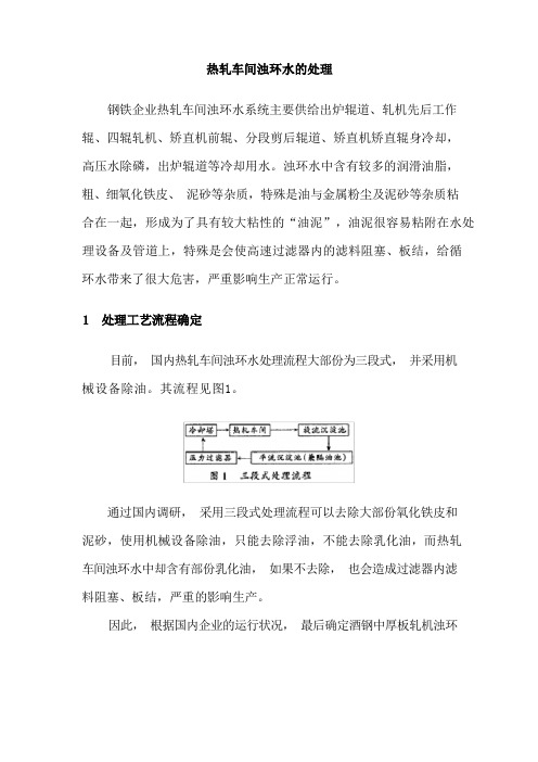
目前,国内热轧车间浊环水处理流程大部份为三段式,并采用机械设备除油。
其流程见图1。
通过国内调研,采用三段式处理流程可以去除大部份氧化铁皮和泥砂,使用机械设备除油,只能去除浮油,不能去除乳化油,而热轧车间浊环水中却含有部份乳化油,如果不去除,也会造成过滤器内滤料阻塞、板结,严重的影响生产。
因此,根据国内企业的运行状况,最后确定酒钢中厚板轧机浊环水处理采用二段式处理工艺流程加旁流化学除油设计方案,其流程见图 2。
该工程设计循环水量:轧线各设备为 1617m3/h,冲氧化铁皮为336m3/h,均通过铁皮沟进入旋流沉淀池,总回水量为 1948m3/h。
处理前 SS500 ~700mg/L、油≤15~20mg/L,处理后SS≤50mg/L,油 5~ 10mg/L。
该工艺的特点是流程简单、投资省、占地小、管理方便。
以自清洗过滤器和化学除油装置代替机械设备除油流程中的二次沉淀池和压力过滤器。
既能去除浮油,又能去除乳化油,同时也能去除悬浮物,达到除油泥双重目的。
磁混凝器设计采用高效能磁混凝技术,即污水经过永磁絮凝器磁化,使细小的氧化铁皮微粒聚合成团,大大增加颗粒沉淀范围和沉降速度,从而使一些难以沉降的细小颗粒得以沉降,进一步提高了沉淀效率。
这种永磁絮凝器有不用电、安全可靠、经久耐用、易于维修等优点。
自清洗过滤器目前国内热轧车间浊环水处理系统大部份采用高、中速过滤器,在实际运行中由于受到水中的油和悬浮物影响,使滤料阻塞和板结。
循环水处理系统
药剂
加药浓度(mg/L)
加药量(t/y)
价格(元/年)
单价(元/吨)
缓蚀阻垢剂
10
5.256
41522.4
7900
杀菌剂
氧化性杀菌剂
100
0.48
4320
9000
非氧化性杀菌剂
50
0.24
2760
11500
总计
48602.4
图1净环循环水系统
单价(元/吨)
缓蚀阻垢剂
10
1.4016
11072.64
7900
杀菌剂
氧化性杀菌剂
100
1.28
11520
9000
非氧化性杀菌剂
50
0.64
7360
11500
除油剂
2
7.884
78840
10000
总计
108792.64
九、空压机循环水量200m3/h,补水量10m3/h
药剂
加药浓度(mg/L)
加药量(t/y)
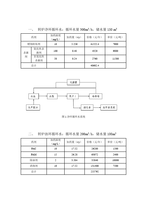
二、转炉浊环循环水:循环水量200m3/h,储水量100m3
药剂
加药浓度(mg/L)
加药量(t/y)
价格(元/年)
单价(元/吨)
PAC
10
17.52
26280
1500
PAM
15
26.28
63072
2400
除油剂
2
3.504
35040
10000
消泡剂
10
17.52
131400
7500
总计
255792
图2浊环循环水处理系统
PureValue-5EZ50逆氧化水系统安装与维护指南说明书
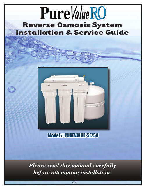
Reverse Osmosis System Installation & Service GuideModel # PUREVALUE-5EZ50Please read this manual carefullybefore attempting installation.IntroductionPlease read this entire service guide prior tobeginning installation.The PureValue reverse osmosis drinking water system has been designed for quick and simple installation and maintenance . By carefully reading this instruction manual and following the operational guidelines you will insure a successful installation and reliable operation. Routine maintenance is essential to the longevity and performance of the system. Filters should be changed every six to twelve months depending on the quality of the feed water supply.CONDITIONS FOR OPERATIONTFC - Thin Film CompositeLong Reach Drinking Faucet1/4” Bluetubing to faucet 1/4” Black tubing from flow restrictor to drain connector 1/4” Redtubing from feedStage 1: Sediment PrefilterStage 3: Carbon Block Stage 2: Carbon BlockStage 5: Carbon Postfilter Stage 4: TFC MembraneStorage Tank1/4" Yellow tubing to tankDrain ConnectorCold waterfeed supplySystem and Faucet DiagramsTDS Monitor (optional)1. Supply Feed VV-WWC-1 & WNV-42. 1/4" Male Connector CI010822W3. Filter Housing 1581254. Filter Housing 'O-Ring 1430265. 5 Micron PreFilter 10132316. Carbon Block 32-250-125-9757. Carbon Block 32-250-125-9758. 1/4" Nipple PN-4-K9. 1/4" Male Elbow CI480822W 10. Check Valve SCV-CI480821W 11. Bracket A-FM60W 12. Auto Shut Off Valve (ASO) FC-ASV4000JG 13. 2.5 Clips PPC212W 15. 1/4" Male Connector CI010822W16. In-Line GAC K2533-JJ 17. Double Clip PPC205W 18. Stem Adaptor PI051222S 19. Reducing Tee PI301208S 20. Ball Valve 707049021. Tank TKE-3200W 22. Air Gap Faucet N103H3PI 23. Drain Connector PDC60414M 24. Membrane 120469425. Flow Restrictor FC-DR300Q/226. TDS Monitor PURCHECK-127. Faucet Connecotor CI3208U7S Please Call Your Local Water Professional For Parts ReplacementStarting Your InstallationPreparationCheck the following list of components to ensure that all parts are packed with your system.1 - Storage Tank 1 - RO System 1 - Faucet1 - Installation KitDetermine the location for the installation of the RO system. Avoid locations where the system might come in contact with hot water pipes or other hazards.Determine the location for the faucet. Check to see that drilling the faucet hole will not damage pipes or wires running underneath the sink.Determine the location for the storage tank. A maximum distance from tank to faucet of 15 feet is possible. The system will produce a faster flow at the faucet with the shortest tubing run from tank to Mounting the Tank Ball ValveNon-Air Gap FaucetNote: Do not tamper with the air valve on the storage tank. It has been preset and screwed on with blue cap by the manufacturers.(1) Wrap the threads on the top of the water storage tank 3 times with plumbers (teflon) tape only. Make sure it is tight, but not over tight.(2) Connect the tank ball valve assembly to the top of the water storage tank.(3) Connect the tube from the RO module to the water storage tank.Fittings and TubingCompression fittings are used throughout the system. To insure a optimal seal, tubing should be cut with the end square. An angled cut or distortion of the tubing will not provide an efficient seal and may cause leaks. To Install a tube, push in the collet until it seats firmly. To remove a tube, push in the collet and pull out the tube.Ball Valve DiagramSource & Drain Water Saddle ValveShut Off the WaterLocate the water shut-off valve for the cold water feed line you choose to use for the supply. Accidentally hooking up the system to the hot supply line will permanently damage the membrane (See Conditions for operation). To assure you are using the cold water line, turn on both the hot and cold faucet. After the water is warm to the touch, feel the pipes under the sink. It will be easy to identify the hot and cold pipes.Close the cold water valve. Turn on the cold water faucet only to assure that the line is completely shut off and the line is drained.. If noshut off valve is located under the sink, turn offthe main supply at the entry to the house.Installing Supply Feed(A) Flex Line: Loosen nut and separate cold water riser tube from faucet shank. Gently bend riser tube so that slip joint fits onto faucet shank. Replace the existing cone washer with new washer provided in installation kit onto cold water riser tube. Reinstall riser tube onto slip joint adapter and tighten.(B) Solid Copper Riser Tube: Same procedure as flex tubing except you must cut a piece of the riser tube about 3/4” to 1” so the slip joint adapter can fit between faucet and riser tube (Teflon tape must be used on slip joint adapter to prevent leaks).Installing the Drain ClampSelect a location for the drain hole based on the design of the plumbing. Position the drain outlet saddle on the drain pipe. Allow adequate space for drilling. Tighten the bolts evenly on both sides. Avoid ing the opening in the drain outlet saddle as a guide, drill a 1/4” hole in the drain pipe. Clean debris from the saddle and threads.NOTE: Some states require the use of an air gap faucet. Check your local plumbing code to assure compliance. Locate the drain connection away from the garbage disposal to prevent potential contamination and system fouling.Supply Feed (Insert)Solid Copper LineFlex LineInstallation - Product Water FaucetDrilling the Faucet HoleThe product water faucet may be installed on any flat surface at least 2” in diameter. Check the underside of the location for interference.Porcelain/Enamel SinksA 3/8” variable speed drill is recommended for this procedure.A spring loaded Relton style drill set is strongly recommended to prevent chipping.The plastic sleeve supplied on the pilot drill is to be positioned on the drill bit against the drill chuck. This prevents the chuck from contacting the porcelain after the pilot hole has been completed.Avoid high motor RPM during the initial cutting of the porcelain as this can cause chipping.Using a carbide tipped drill bit, drill a pilot hole completely through the porcelain and the material underneath.Place the spring loaded porcelain saw into the drill chuck. Make sure the pilot guide is inserted tightly. Insert the pilot guide into the pilot hole. Push down gently on the drill motor to apply light pressure to the porcelain surface. Start the drill motor turning as slowly as possible.After the initial cut has started, motor speed may be gradually increased. The cut may require three to four minutes to complete. Going faster could result in excessive chipping. This saw is used to cut the porcelain only. Be sure a complete ring has been cut through the porcelain to the metal underneath. Place the finish hole saw into the drill chuck. Make sure the pilot guide is inserted tightly. Insert the pilot guide into the pilot hole. Begin cut using a slow speed and light pressure until the metal has been penetrated.Stainless Steel SinkMake a small indent to mark the desired drilling location using a center punch. Drill a pilot hole with a 1/8” metal drill bit. Enlarge the hole using a 3/8” metal drill bit.Tile Counter TopFollow the procedures outlined in the Porcelain/ Enamel Sinks section.Faucet InstallationOnce the hole has been drilled in the sink, the faucet may be located in the hole. Be sure the faucet body, faucet base, and the rubber faucet base washer are in place above the sink.Install the star lock washer and nut, then tighten firmly while aligned faucet in the desired direction.Additional Point of Use Connection NOTE: Icemakers typically use 1/4” tubing as the water feed line. Use a reducing union fitting to make this connectionTo connect an additional point of use (icemaker, extra faucet, etc.), place a ‘T’ connector in the 1/4” line between the faucet and the RO system.Drilling with the recommended Relton cutterActivation, Troubleshooting, MaintenanceActivating the System For the First Time Make sure all water supply/drain lines are secure and free from leakage.Slowly turn the saddle valve counterclockwise until fully open. Check stem seal for leakage. If necessary tighten stem nut lightly.Turn storage tank valve one quarter turn counterclockwise to open the valve (the handle should be in line with the tubing as it enters the connection).Open the product water faucet and let the water flow until all the air has been expelled from the system. This will take about an hour.Close the product water faucet. In 30 minutes, check the connections for leaks and correct if necessary.Maintenance- Imperative to follow the sequence as outlinedNote that filters are labeled for easy servicing.1) Open the RO faucet and let the tank drain completely. Leave the faucet open until the filter change is complete.2) Remove the pre-sediment cartridge.3) Remove the pre-carbon cartridge.4) Remove the membrane cartridge - The membrane may be reused indefinitely as long as the TDS level and othertroubleshooting guidelines are met.4) Remove the post-carbon cartridge.5) Install the new filters.6) Turn on the system and inspect for leaks.7) Drain the first tank of water after changing the filters before drinking. When the membrane is changed, drain thefirst two tanks of water before drinking.CONDITIONS FOR OPERATIONThe PureValue reverse osmosis system is warranted to be free from defects in materials and workmanship under normal use within the operating parameters listed below. For a period of twelve months from the date of purchase PureValue will repair or replace any part of the reverse osmosis system with the exception of the filters and battery.Conditions of WarrantyThe above warranty does not apply to any part of the PureValue reverse osmosis system that is damaged because of neglect, misuse, alteration, accident, misapplication, physical damage, fouling, and/or scaling of the membrane by minerals, bacterial attack, sediment or damage caused by fire, freezing, hot water, or an act of God.PureValue assumes no warranty liability in connection with this reverse osmosis system other than as specified herein. PureValue shall not be liable for consequential damages of any kind or nature due to the use of PureValue products.Warranty ServiceWarranty service will be provided by PureValue under the following conditions:1) Contact your local dealer who will obtain return authorization instructions.2) Ship the unit or part freight prepaid for warranty evaluation or service. Unit must be returned in the original carton or packaged to prevent possible damage. Systems or parts covered under thewarranty shall be repaired (or, at our option replaced) and returned without charge.PureValue Manual PureValue Limited Warranty。
《江河流域水污染自动监测和应急处理系统》软件需求分析规格说明书
《江河流域水污染自动监测和应急处理系统》软件需求分析规格说明书版本号:1.0作者:王淑升张敏芳赵华成日期: 2009-8-25文档修订抄送人:高级管理者、研发经理、客户经理、客户代表、项目组成员、SCCB(在项目实际应用时最好写明抄送人的姓名)目录1.概述.................................................................................. 错误!未定义书签。
1.1编写目的.......................................................................... 错误!未定义书签。
1.2背景.................................................................................. 错误!未定义书签。
1.3适用范围.......................................................................... 错误!未定义书签。
1.4术语定义.......................................................................... 错误!未定义书签。
2.系统说明.......................................................................... 错误!未定义书签。
3.整体系统划分.................................................................. 错误!未定义书签。
3.1子系统《黄河中下游水污染扩散计算系统》.............. 错误!未定义书签。
3.1.1仿真计算功能.................................................... 错误!未定义书签。
- 1、下载文档前请自行甄别文档内容的完整性,平台不提供额外的编辑、内容补充、找答案等附加服务。
- 2、"仅部分预览"的文档,不可在线预览部分如存在完整性等问题,可反馈申请退款(可完整预览的文档不适用该条件!)。
- 3、如文档侵犯您的权益,请联系客服反馈,我们会尽快为您处理(人工客服工作时间:9:00-18:30)。
芜湖新兴三山工业区高线水系统工程浊环水处理系统功能规格书
河北新烨工程技术有限公司
2011、12
浊环水处理系统功能规格书本浊环水处理系统分为浊环水处理站和过滤间两部分,浊环水处理站处理两条高速线材及一条小棒生产线的浊环水,并预留处理能力为1500m³/h 稀土磁盘位置,浊环水处理能力7500m³/h,预留处理能力1500m³/h;过滤间主要处理两条高速线材需过滤的浊环水,浊环水最大过滤水量1120m³/h,预留场地给小棒生产线及扩产所需的过滤浊环水过滤。
1.工艺概述
经旋流井处理后的浊环水用泵送入稀土磁盘,经稀土磁盘处理后的净化水自流入平流池再流至吸水井,浊环提升泵站设提升泵,部分水提升至高速过滤器净化后回联合泵站冷却塔,冷却塔出水自流至联合泵站循环水池,由联合泵站的供水泵循环使用;另一部分直接回联合泵站冷却塔,冷却塔出水自流至联合泵站循环水池,由联合泵站的供水泵循环使用。
稀土磁盘出渣接至磁力压榨机,压榨后得干渣和滤液,干渣排入渣池由抓斗装车外运;滤液排至滤液池后用潜污泵送回至旋流井。
2.浊环水处理站
浊环水处理站分为渣池跨、稀土磁盘工作平台跨、浊环水提升泵站和药剂库及备件库。
浊环水处理站渣池跨设3个4.8X10X2m渣池和3个2.7X10X3m滤液池,滤液池顶设5台两辊磁力压榨脱水机,各滤液池内设1台潜污泵,渣池上设1台抓斗吊钩两用桥式起重机用于抓渣。
滤液池设有液位测量在联合泵站控制室显示,液位高于1.6m控制室内报警。
稀土磁盘工作平台跨设有3个10X16.5X5m平流池,平流池内设配水花墙、导流墙和3台圆盘除油机;平流池上4m工作平台2组SMDD-1500X2和1
台SMDD-1500稀土磁盘,设3台轴流风机和1台检修用悬挂式电动单梁起重机。
浊环水提升泵站设30X12X5m吸水井,吸水井上设3台过滤浊环水提升泵、3台水冷浊环水提升泵、3台普通浊环水提升泵、3台轴流风机和1台检修用悬挂式电动单梁起重机,水泵均为2用1备;吸水井设有液位测量在联合泵站控制室显示,液位高于3.4m报警、液位低于0.3m报警、液位低于±0.00浊环水提升泵站内所有水泵停泵。
药剂库及备件库设加药装置。
提升泵控制形式为机旁控制和集中监控,就地控制优先。
水泵出口压力和出口总管流量、温度均在联合泵站控制室集中显示。
当水泵出口压力低于正常工作压力0.2MPa,报警并自动启动备用泵。
稀土磁盘控、磁力压榨机、圆盘除油机和加药装置制形式为机旁控制和集中监视。
潜污泵和轴流风机为机旁控制。
3.过滤间
过滤间内设6台GSL-3高速过滤器,单台过滤水量280m³/h,1台用于净环旁滤,5台用于浊环过滤(4用1反洗);设160 m³反洗水池,池顶设2台150WFB-BD无密封自吸泵,过滤间设3t检修天车一台,设4台T35-11 No.5轴流风机。
过滤器配套电动阀和自吸泵控制形式为机旁控制和集中监控,就地控制优先。
过滤器厂家配套PLC控制过滤器阀门进行反洗,5台运行的过滤器应依次连续进行反洗,反洗第一台过滤器前先开启反洗水供水泵、启泵后打开过滤器反洗水进水电动阀时间(约40秒)应根据现场调试确定,过滤器配套的
阀门开关时间及顺序由过滤器厂家自带PLC控制。
浊环过滤器反洗时应先打开备用过滤器的进水阀,使1台浊环过滤器反洗时仍有4台过滤器在正常运行,最后一台浊环过滤器反洗后作为备用过滤器待下次反洗时开启;净环旁滤过滤器反洗时应先停净环旁滤供水泵,停泵半小时后再启泵;所有过滤器反洗完后停反洗水供水泵。
检修天车和轴流风机为机旁控制。
反洗水池设有液位测量在联合泵站控制室显示,液位高于-0.5m报警、液位低于-2.5m报警、液位低于-3.0停泵。
控制室根据液位远程启泵,水泵出口压力、流量均在控制室显示;自吸泵出口压力低于正常工作压力0.15MPa,报警并自动启动备用泵。