MOS-3e-10 《现代操作系统》Andreww S.Tanenbaum配套课件ppt
mos管的分类及作用

mos管的分类及作用
MOS管(Metal-Oxide-Semiconductor Field-Effect Transistor)是一种重要的半导体器件,主要用于放大、开关和模拟电路等方面。
根据其结构和工作原理的不同,MOS管可以分为以下几类:
1.增强型MOS管(NMOS):其栅极(Gate)与漏极(Drain)相连,漏极与源极(Source)之间形成了一个P型半导体区域。
当栅极施加正电压时,P型区域中的自由电子(空穴)被吸引到N型区域中,形成了一个导电通道,使得源极和漏极之间的电流能够流过。
增强型MOS管主要用于开关和放大器等方面。
2.耗尽型MOS管(PMOS):其栅极与源极相连,源极与漏极之间形成了一个N型半导体区域。
当栅极施加负电压时,P型区域中的自由电子(空穴)被排斥出去,形成了一个电导率很低的区域,使得源极和漏极之间的电流不能够流通。
耗尽型MOS管主要用于开关和放大器等方面。
3.P通道MOS管(PMOS):其栅极与源极相连,漏极与N型半导体区域相连。
当栅极施加负电压时,P型区域中的自由电子被吸引到N型区域中,形成了一个导电通道,使得源极和漏极之间的电流能够流通。
P通道MOS管主要用于开关和放大器等方面。
4.N通道MOS管(NMOS):其栅极与源极相连,漏极与P型半导体区域相连。
当栅极施加正电压时,N型区域中的自由电子被吸引到P型区域中,形成了一个导电通道,使得源极和漏极之间的电流能够流通。
N通道MOS管主要用于开关和放大器等方面。
总的来说,MOS管具有体积小、功耗低、工作频率高等优点,在现代电子技术中得到广泛应用,如计算机、通信、工业控制等领域。
电动执行器操作手册
SENSORO物联网解决方案及应用案例

产品概述
α低功耗物联网通信芯片(α-SWC11A/B-S)
α Chip(SWC11A/B-S)是SENSORO设计的低功耗物联网 无线通信芯片,内嵌近场和远场数据通信协议,支持双 重感知网络。
灯井监控项目
试点项目概要
选取4个塔安装基站,覆盖望京核心地区试点 选取望京地区主干道灯井,验证方案功能完备,
信号传输稳定 物联网云端功能定制展现 实施与验证
灯井监控装置, 安装于井下
云端监控终端设备状态,动态优
化IoT-WAN,并基于不同应用场景 管理终端设备
SENSORO
端到端物联网解决方案
基站远距离传输 大规模传感网络数
据通信
数千级数量终端接
入
多种通信方式支持
携手北京铁塔大规模部署物联网基站,目标覆盖北京市五环内区域,为 SENSORO快速推广基于物联网的端到端解决方案提供强大支撑
产品概述
β低功耗物联网通信模块(β-MD11A-S)
β-MD11A-S是SENSORO设计的低功耗物联网通信模块, 内嵌近场和远场数据通信协议;支持双重感知网络。
一方面基于BLE的低功耗近距离无线通信技术,支持多 种近场通信协议,或自定义协议,打通物理世界到移动 互联网数据通路;另一方面,基于IoT-WAN低功耗网络, 提供远距离数据上下行通路,直接支撑云端远程监测和 控制。β-MD11A-S双重感知技术,连接物理世界、移动 互联网和互联网,实现物理世界和数字世界的融合。
SENSORO NETWORK
Connect the Physical and Digital World
科布姆马斯系统:高性能纤维复合电视杆系统说明书

Cobham Mast Systems Cobham Mast Systems is the world leader in high performance composite telescopic mastsThe most important thing we build is trustTELESCOPICMAST SYSTEMSThe lightweight telescopic masts are designed to meet the most demanding requirements of mobile communication systems SUPERIOR PERFORMANCESuperior performance,reliability and user-friendliness through theuse of advanced compositematerials, design andattention to detailANTENNAPOINTING DEVICESA wide rangeof different antennapointing devices areavailableVEHICLEMOUNTING KITSMounting kits areavailable for vehicles,shelters and containersattention to detail. The masts are designed to meet the most demanding requirements of transportable communications, intelligence, surveillance, reconnaissance and broadcast systems, and are employed whenever there is a need to optimize system performance. The masts are used extensively by various defence forces around the world and are also applicable to the police, fire fighting, rescue, and other emergency services. Combat-proven in the toughest conditions, Cobham Mast Systems’ products have earned their enviable reputation for rugged reliability and superior performance in arctic, tropical and desert environments.Cobham Mast Systems manufactures seven main product lines: TM-, TR-, EX-, EXL- and EXB-masts, telescopic lifting poles and tripods including accessories for deployment. Masts are available from vehicle mounted unguyed masts to 50 m stand alone field masts. Every detail is designed for reliability and quick and safe operation. Masts exceed the military’s requirements for maintainability and require very little service. Cobham Mast Systems’ telescopic masts have been used extensively around the world and have proven to be fully operational after long exposure to sand, dust, ice or snow.Quality and TestingCobham Mast Systems’ quality system fulfills the requirements of ISO 9001 and AQAP 2110 standards.The carbon and glass fiber composite masts have been proven to meet MIL-STD 810 F requirements to function in all extremes of environmental conditions. Masts are also tested against lightning strikes.Antenna Brackets . . . . . . . . . . . . . . . . . . . . . . . . . . . . . . . . . . . . . . . . .18Vehicle Mounting Kits . . . . . . . . . . . . . . . . . . . . . . . . . . . . . . . . . . . . .19WPU and Quality & Testing . . . . . . . . . . . . . . . . . . . . . . . . . . . . . . . .20Services and Mast Questionnaire . . . . . . . . . . . . . . . . . . . . . . . . . .22 Typical Mast Heights and Top Loads ArrayMAST SERIES HEIGHT TOP LOADEXB 6 - 14 m20 -110 kgEXL10 - 50 m50 - 120 kgEX 5 - 20 m20 - 50 kgTX 4 - 8 m10 - 25 kgTR 4 - 12 m 5 - 10 kgTM 4 - 8 m 2 - 5 kgTripods 2 - 5 m 2 - 100 kgMaximum top load depends on mast height and antenna size.3top maximum deflection requirements, EXB-masts utilize composite tube sections varying from pure glass fibre to pure carbon fibre.EXB-masts are extended and retracted utilizing hoisting belts driven by a winch. This is aneffective, well-proven technique which is more reliable under severe operating conditions (especially sand and dust). EXB-Masts have a double-belt system – one belt is used for mast extension, the second belt is used to provide positive retraction to assure proper operation under adverse conditions of wind and slope. EXB-masts are equipped with an automatic latch mechanism for controlling the order in which tube sections extend. The winch is operated by an electric Winch Power Unit(WPU) with remote control, with WPU versions available for either AC or DC power supplies. A manual hand crank is provided as a back-up for power failure.EXB-masts can be painted in customer specific colours.Typical EXB-MastsMAST TYPE EXB269/6-1.2EXB269/10-1.8EXB333/10-1.7EXB333/12-1.75Extended height (m) 6101012 Transportation length (m) 1.2 1.8 1.7 1.75 Max. vertical top load (kg) 554511050 Max. wind area A (m²) 0.20.20.60.3 Max. wind speed (m/s) 25253630 Sections7789 Mast weight (kg) 111120127150 Above listed masts are examples. Other lengths with different top load specifications are available at request.5composite material. Masts are delivered with full field deployment accessory kits and they can be supplemented with a wide range of mounting kits for vehicles and shelters.EXL-masts are deployed by two or threepersons and are elevated with a hand-cranked winch or by an optional electric winch motor unit. The entire mast is rotatable by 360°. In EXL-masts sections open one by one and an automatic mechanical locking mechanism allows guying each lower section separately during winching up. This allows safe handling of higher top loads especially under windy conditions.EXL-masts can be painted in customer specific colours.Typical EXL195-Masts MAST TYPEEXL195/ 24-3.9EXL195/ 30-5EXL195/ 34-5.6EXL195/ 50-7.6Extended height (m)24303450Transportation length (m) 3.9 5.0 5.67.6Max. vertical top load (kg) 507510050Max. wind area A (m²) 1.0 1.5 1.5 1.0Max. wind speed (m/s) 35353530Guy radius (m)16252045Guys and levels 4x44x54x54x7Sections10888Mast weight (kg)108125132160Accessories weight (kg)6485105120Above listed masts are examples. Other lengths with different top load specifications are available at request.Transportation length (m) 3.8 4.2 4.3 5.0Max vertical top load (kg) 60605550Max wind area A (m²) 1.5 1.5 1.00.8Max wind speed (m/s) 35353535Guy radius (m)12141618Guys and levels 4x34x44x44x5Sections7788Mast weight (kg)72808698Accessories weight (kg)52626773Above listed masts are examples. Other lengths with different top load specifications are available at request.7be supplemented with a wide selection ofmounting kits for vehicles and shelters.EX-masts can be deployed by one to threepersons and are elevated with a hand-crankedwinch or by an optional electric winch powerunit. The entire mast is rotatable by 360°.EX-masts can be painted in customerspecific colours.8Transportation length (m) 2.0 2.3 3.4 4.0Max. vertical top load (kg) 40403535Max. wind area A (m²) 1.2 1.0 1.20.9Max. wind speed (m/s) 35353535Guy radius (m)671012Guys and levels 4x24x24x34x3Sections6666Mast weight (kg)24273641Accessories weight (kg29294041Above listed masts are examples. Other lengths with different top load specifications are available at request.Typical EX141-Masts MAST TYPEEX141/ 10-2.4EX141/ 15-3EX141/ 18-4EX141/ 20-4.3Extended height (m)10151820Transportation length (m) 2.4 3.0 4.0 4.3Max. vertical top load (kg) 45454050Max. wind area A (m²) 1.5 1.5 1.20.75Max. wind speed (m/s) 35353535Guy radius (m)7101212Guys and levels 4x24x34x34x3Sections6566Mast weight (kg)25414845Accessories weight (kg31403945Above listed masts are examples. Other lengths with different top load specifications are available at request.9TR-MastsLightweight telescopic TR-masts are push-up masts for heights up to 12 meters and for5-10 kg top loads. Mast sections are pushed out and locked in place with mechanical latches one by one.TR-masts are made of glass fibre composite material. The masts can be supplemented with a wide range of mounting kits for vehicles and shelters.Lightweight telescopic TX-masts, a variant of TR-masts, are push-up masts for heights up to 7 meters and for a max. 25 kg top loads.TX-mast sections are pulled out horizontally to their full length and the mast is then lifted up in vertical position.TR- and TX-masts can be painted in customer specific colours.Mast weight (kg)9111213Accessories weight (kg)11111111Above listed masts are examples. Other lengths with different top load specifications are available at request.Typical TM-Masts MAST TYPE TM51/ 4-1.2TM51/ 6.3-1.8TM58/ 4.8-1.2TM58/ 7.6-1.8Extended height (m) 4 6.3 4.87.6Transportation length (m) 1.2 1.8 1.2 1.8Max. vertical top load (kg) 5355Max. wind area A (m²) 0.10.050.10.1Max. wind speed (m/s) 25252525Mast weight (kg)2.83.64.25.2Above listed masts are examples. Other lengths with different top load specifications are available at request.11Typical Telescopic Lifting PolesPOLE TYPE TLP61/10-2.75TLP61/ 15-4Extended height (m) 1015Transportation length (m) 2.754Max. vertical top load (kg) 33Pole weight (kg)9.512.5Above listed poles are examples. Other lengths withdifferent top load specifications are available at request. 121315Rotator-tilter is an antenna pointing device forpointing the antenna system both horizontally(azimuth) and vertically (elevation).Tilters and rotator-tilters are operated from theground level with maneuvring ropes. Antennascan be mounted directly on the tilter orrotator-tilter or on antenna specific brackets. 16available for antenna rotators and double rotators.Remote Control Unit (RCU)Rotator can be controlled with RCU. Operation voltage is 24 VDC.17181920212223Customers around the world put their trust in CobhamDesignedbyIdealMainosOy,Siltakatu20,80100Joensuu,FINLAND–Telephone:+358(0)207288291e-mail:********************IDEALMAINOS 01/10Whilst every effort is made to ensure the accuracy of the information contained in this brochure, no responsibility can be accepted for any errors or omissions. All photography is copyright and is used with thanks to the respective owners.For further information please contact:Cobham Mast Systems Muovilaaksontie 8FI-82110 Heinävaara FinlandT: +358 (0)13 737 7111F: +358 (0)13 737 7113**********************Mastsystem Int’l Oy trading as Cobham Mast Systems This paper contains 50% recycled fibres and is bleached in a totally chlorine free process. The virgin fibre content of this paper is elemental chlorine free and comes from managed forests./mastsystems。
欧圣 手持控制器 HBA 使用说明书

These operating instructions are valid only in connection with the data sheet of the rele-vant hand-held pendant station HBA and with the operating instructions of the relevant HBA handwheel!Correct useMachine installations in manual mode can be operated with hand-held pendant stations.Handwheels are used as part of an overall higher-level control system.Their use, installation and operation are permissible only in conformity with these operating instructions.Incorrect useHand-held pendant stations on their own must not be used as safety components for avoiding hazar-dous states in a machine installation.General functionHand-held pendant stations make it possible to operate a machine installation, for instance, in manual mode.Function of individual componentsThe hand-held pendant station may consist of the following components: HandwheelEMERGENCY-STOP device Enabling switches Selector switches PushbuttonsHBA handwheelThe electronic HBA handwheel is a universal pulse generator for manual shaft positioning.An output of 100 or 25 square-wave pulses per revolution is available. A second phase-shifted output allows the connected controller to detect the direction of movement.The pulses are evaluated in the controller.For details, please see the Electronic HBA handwheel operating instructions.EMERGENCY-STOP deviceThe EMERGENCY-STOP device is designed to be mani-pulation-proof in accordance with IEC 60947-5-1/EN ISO 13850.Enab ling switches, selector switches,pushbuttonsThese components are used to transfer additional information to the higher-level machine controller.AssemblyHand-held pendant stations are not used exclusively at a single site. The stations can be stored using a mounting magnet on the rear of the device or a holder.Electrical connectionAlways shield connecting leads.Ground the shield at the open end of the lead at a central grounding point, e.g. in the distribution board or in the control cabinet, over a large sur-face, with low resistance and with low inductance. In the case of leads with plug connectors, ensure that the connection type is EMC-compliant.Original connecting leads must not be shortened. G iven an extension or other modification to the connection cable, the operator must ensure that the valid EMC protection requirements are observed. Do not install connecting leads in the immediate vicinity of interference sources.Authorization according to:Operation with UL-class 2 power supply only.Connection leads of hand-held pendant stations in-stalled at the application site must be separated from all movable and permanently installed leads and non-insulated active parts of other installation parts which operate with a voltage of over 150 V, in such a way that a constant clearance of 50.8 mm is observed. This does not apply if the movable leads are equipped with suitable insulation materials which possess an identical voltage stability to the other relevant installation parts or higher.Service and inspectionEUCHNER handwheels require no maintenance.Handwheels may only be repaired by the manufac-turer.To clean the handwheels, only use solvent-free cle-aning agents and a soft cloth.Disclaimer of liabilityThe company is unable to accept liability in the following cases:if instructions are not followedif the safety instructions are not followedif the units are electrically connected by unautho-rised personnelif any external intervention occursDo not open hand-held pendant stations!Do not throw or drop the hand-held pendant stati-ons!LISTEDPOW. CONV. EQ.82HAEUCHNER GmbH + Co. KG Kohlhammerstra ße 16D-70771 Leinfelden-Echterdingen Tel. +49/711/75 97-0Fax +49/711/75 33 16www.euchner.de ***************S u b j e c t t o t e c h n i c a l m o d i f i c a t i o n s ; n o r e s p o n s i b i l i t y i s a c c e p t e d f o r t h e a c c u r a c y o f t h i s i n f o r m a t i o n .© E U C H N E R G m b H + C o . K G072850-05-02/12 (T r a n s l a t i o n o f t h e o r i g i n a l o p e r a t i n g i n s t r u c t i o n s )ColourGrey RAL 7040/Black RAL 9004Weight1.3 kg Operating temperature 0 °C ... +50 °C Storage temperature -20 °C ... +50 °CHumidity, max.80 %(condensation not permissible)Degree of protection to the frontIn accordance with EN60529 / IEC529IP 65In accordance with NEMA 250-12Resistance to vibrationVibrations (3 axes)DIN/IEC 68-2-6Shock (3 axes)DIN/IEC 68-2-27EMC protection requirements EN 61000-6-2in accordance with CEEN 61000-6-4Switching elements Max. 2 NC contactsUtilization categoryDC-13according to IEC 60947-5-1U e =24 V / I e= 3 A Resistive loadAC 30 V / 0.4 ADC 30 V / 0.1 A Switching voltage, max.30 V DC Switching current, max.0.1 A Switching capacity, max.1 VA see wiring diagramSwitching voltage, max.25 V Switching capacity, max.0,2 VAwww.euchner.deTechnical data, handwheelSee relevant operating instructions for HBA hand-wheel.AccessoriesSee EUCHNER catalogue for hand-held pendant stations or www.euchner.de.。
伯纳德电动执行器产品资料
rotork iq执行器,其主要的缺点有:1。
执行精度不高,只能达到1%左右。
2。
位反板容易损坏。
使位置反馈常常失灵。
3。
内部动力输出轴套采用的是铜质,容易磨损。
4。
伺放板容易损坏。
5。
其机械限位设计不好,用了两个螺帽固定,容易松动,导致机械限位跑,导致阀门出现关不下去的故障。
当然有优点,死区小,定位精度高,现在有不用接触器用可控硅控制电流通断的,但价钱较高,感觉性价比比不上西博斯FLASH 5。
电机也容易烧坏,老要换限位开关,老式执行器的接触器易坏我们厂送风机动叶调节用的是ROTORK,使用情况还可以,原来出现的问题是位置反馈机构的齿轮传动部分因为只用顶丝固定,时间长容易松动,造成反馈输出不变,还因此跳过机。
ROTORK执行器反馈和定位用的电位器不同,如果执行机构长期在一个位置运行,会发生反馈电位器磨损现象,需更换电位器。
引风机和一次风机用的是原装伯纳德执行器,在我们厂简直糟透了,经常发生执行器自己全开,原因一直找不找,为此我们已经换了十几块定位板了,每次换完板子可以稳定几个月,每块板子价格大概3000元,备品有好几台。
另外,反馈电位器也经常坏。
最近我们正在考虑换型,所以在调研AUMA和SIPOS。
AUMA我们厂用在磨煤机冷、热风调门上,环境温度较高,出现过好几次电机烧坏现象,交流接触器,电源板也容易出问题,调整起来还是比较方便的,但是内部板件太多,共有5块,价格也比较贵,最贵的板子定位板一块将近10000元,我觉得AUMA的好处是机械机构比较好,可以说免维护。
在环境不太好的地方最好使用分体安装,这样效果可能好些。
没有使用过的执行器就是SIPOS,希望能为我提供使用信息。
谢谢!ROTORK IQ在我厂应用中出现一倒厂用电既烧保险现象。
伯纳德性能较稳定,但出现过一次电位器不随执行器转动事件。
SIPOS的容易出现死机,重新送电恢复我厂用的最多的是天津七厂的伯纳德执行器,但是板子经常坏。
出现几次不明原因的全开。
MOS概述及应用
MOS概述及应用MOS(Metal-Oxide-Semiconductor)是一种常见的半导体器件制造技术,也是现代电子技术的基础之一、MOS技术是通过在半导体材料上沉积一层氧化物绝缘层,并在其上面构建金属-氧化物-半导体(Metal-Oxide-Semiconductor)结构的方式来制造电子器件。
MOS技术具有制造工艺简单、器件结构丰富、功耗低、体积小等优势,并在很多领域得到了广泛应用。
首先,MOSFET是最常见和最广泛使用的MOS器件之一、MOSFET是一种用于放大或开关电流的器件,常被用于构建电子电路中的放大器、开关等。
MOSFET通过调节栅极上的电压来控制其漏源电流,其结构简单、工艺容易控制和集成度高等特点,使其成为现代电子器件中最重要的构建基石之一其次,CMOS技术是另一种重要的MOS技术,其应用广泛。
CMOS是一种采用N型和P型的MOSFET相结合的技术,以达到功耗低、速度快、可靠性高等优势。
CMOS技术广泛应用于数字逻辑电路、微处理器、存储器等领域。
它的低功耗使得电子设备的待机时间更长,使得电池寿命更长,同时也减少了电子设备的发热问题。
此外,MOS技术还应用于DRAM等重要的存储器件中。
DRAM是一种动态随机存储器件,其结构和工作原理与MOSFET类似。
DRAM通过调节栅极上的电压,控制存储单元中的电荷状态,实现数据的读写操作。
DRAM具有高集成度、存储容量大等特点,成为了主流的计算机存储器件。
此外,MOS技术还应用于传感器、光电器件和液晶显示等领域。
例如,MOS技术可以用于制作微机械传感器,如加速度传感器、压力传感器等。
此外,MOS技术还可以制造光电器件,如光电晶体管、光电二极管等。
此外,液晶显示器中的背光源也经常采用MOS技术驱动。
总之,MOS技术是一种常见和重要的电子器件制造技术,应用领域广泛。
从集成电路到存储器,再到传感器和显示器等,MOS技术在现代电子技术中扮演着重要的角色。
现代操作系统Modern Opera System -3e-01

Figure 1-8. (a) A quad-core chip with a shared L2 cache. (b) A quad-core chip with separate L2 caches.
Memory (1)
Figure 1-9. A typical memory hierarchy. The numbers are very rough approximations.
Figure 1-5. A multiprogramming system with three jobs in memory.
ICs and Multiprogramming(cont.)
•Spooling( Simultaneous Peripheral Operation On Line) Input spooling is the technique of reading in jobs, for example, from cards,onto the disk, so that when the currently executing processes are finished,there will be work waiting for the CPU. Output spooling consists of first copying printable files to disk before printing them, rather than printing directly as the output is generated. •Timesharing A kind of OS •Typical OS UNIX Linux
Figure 1-3. (c) Operator carries input tape to 7094. (d) 7094 does computing. (e) Operator carries output tape to 1401. (f) 1401 prints output.
dmos说明

DOMS的全称是Double-diffused Metal Oxide Semiconductor.DMOS工艺:DMOS(双扩散MOS)晶体管是针对大电流、高电压而优化设计的。
为了提高击穿电压而将这类元件设计成长沟道结构。
将几个单元并联来实现大电流(低的导通电阻)和高能量密度。
DMOS工艺比逻辑工艺具有更厚的栅极氧化层,这样可以制造出更坚固的器件。
如果这些基本的工艺以逻辑方式组合起来,可以得到下列不同的组合工艺,根据它们的专有特性可以适用于特定的应用领域。
1 引言汽车电子技术发展迅猛,多种新型电子控制装置几乎全面进入整车各系统,极大地提高了汽车性能,有专家预测:今后十年内,汽车电子及其相关产品在整车的成本比例将从目前的平均20%上升到32%,其发展速度从10%提高到20%,耗电量不断增加,导致车内电力负载年增加100W以上,具有电能使用效率高、传输快捷、转换容易、控制灵活等一系列特性的车内电器日趋增多,采用电磁或电动执行器替代液压和气压传动执行器已成为一种趋势,一些带电的机械装置正加速转变为带机械的电子装置,各种线控系统的研发目标是取代液压与机械控制系统,极大地增添了汽车电气系统的负荷。
为解决这一发展瓶颈,唯一可行的办法是车内供电直流电压由14V转向42V电气系统,或14/42V双电压电气系统(按电器设备和电子装置消耗功率的大小分为两组,耗电功率较大的一组使用42V供电系统,而耗电较小的一组采用14V供电系统)提高交流发电机电压以增大其输出功率,供电容量将从目前的1.5kW左右提高到今后的5kW以上,电气化控制以及新的供电系统中,需要大量采用功率MOSFET(金属-氧化物-半导体场效应晶体管),进行功率变换、控制与驱动各种大功率的负载,同时,先进的功率MOS技术也促进新型汽车电控系统的发展与提高,据报道,一辆轿车中所使用的功率MOS器件至少有数十只,甚至上百只,在汽车电气系统的功率流向和分配管理诸方面发挥重要作用,使电能的应用处于最佳状态。
MOS管及简单CMOS逻辑门电路原理图
MOS管及简单CMOS逻辑门电路原理图现代单片机主要是采用CMOS工艺制成的。
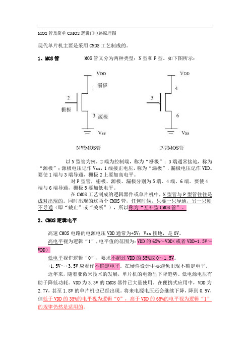
1、MOS管 MOS管又分为两种类型:N型和P型。
如下图所示:以N型管为例,2端为控制端,称为“栅极”;3端通常接地,称为“源极”;源极电压记作Vss,1端接正电压,称为“漏极”,漏极电压记作VDD。
要使1端与3端导通,栅极2上要加高电平。
对P型管,栅极、源极、漏极分别为5端、4端、6端。
要使4端与6端导通,栅极5要加低电平。
在CMOS工艺制成的逻辑器件或单片机中,N型管与P型管往往是成对出现的。
同时出现的这两个CMOS管,任何时候,只要一只导通,另一只则不导通(即“截止”或“关断”),所以称为“互补型CMOS管”。
2、CMOS逻辑电平高速CMOS电路的电源电压VDD通常为+5V;Vss接地,是0V。
高电平视为逻辑“1”,电平值的范围为:VDD的65%~VDD(或者VDD-1.5V~VDD)低电平视作逻辑“0”,要求不超过VDD的35%或0~1.5V。
+1.5V~+3.5V应看作不确定电平。
在硬件设计中要避免出现不确定电平。
近年来,随着亚微米技术的发展,单片机的电源呈下降趋势。
低电源电压有助于降低功耗。
VDD为3.3V的CMOS器件已大量使用。
在便携式应用中,VDD为2.7V,甚至1.8V的单片机也已经出现。
将来电源电压还会继续下降,降到0.9V,但低于VDD的35%的电平视为逻辑“0”,高于VDD的65%的电平视为逻辑“1”的规律仍然是适用的。
3、非门非门(反向器)是最简单的门电路,由一对CMOS管组成。
其工作原理如下:A端为高电平时,P型管截止,N型管导通,输出端C的电平与Vss保持一致,输出低电平;A端为低电平时,P型管导通,N型管截止,输出端C的电平与V DD一致,输出高电平。
4、与非门与非门工作原理:①、A、B输入均为低电平时,1、2管导通,3、4管截止,C端电压与V DD 一致,输出高电平。
②、A输入高电平,B输入低电平时,1、3管导通,2、4管截止,C端电位与1管的漏极保持一致,输出高电平。
Oelmann SME Tools User Manual

Oelmann SME Tools User Manual18.01.2018Release 0216CONTENTS.................................................................................................................... CONTENTS 2 ................................................................................................................... Introduction 3........................................................................................... Purpose and compatibility 3 Software files source 3................................................................................................................................................................................................ Installation of the software 3................................................................................................ Launching the software 4 .......................................................................................................... Software Settings 6.............................................................................. Operating modes of the software 6 Combined mode / dashboard 6 Inductive (IOS) Beacon Monitor mode 7 POCSAG Monitor mode 7 Bluetooth Monitor mode 8 Serial Monitor mode 8................................................................................................... Exit from the software 9................................................................................................... Uninstall the software 9IntroductionThis User Guide describes the purpose, installation, operation and settings of the Oelmann SME Tools software application.Purpose and compatibilityThe purpose of Oelmann SME Tools software is diagnostics, factory testing and operational verification of devices equipped with genuine Oelmann SM660 Series modules, in terms of the operation of devices with these modules and its functions. Android version of SME Tools is designed to work on Oelmann SME devices with Android OS versions 5…7.PC version of SME Tools software is designed to work on devices with OSX/Linux/Windows OS equipped with JVM 1.8 or later.Software files sourceInformation on the SME Tools software, the latest official release of of, application manual and training video are always on the web page:https:///support/sme/tools/Note: The SME Tools software version for PC is used in the manufacture of SME devices, requires the original Oelmann hardware technological tools, and it is available for Oelmann technological partners on request.Installation of the softwareThe sequence of steps for installing the software is listed below:1.On the link above you will receive the binary file "OE_SME_Tools_app.apk".2.Connect your SME device to the PC on which this file is located.3.According to the version of Android used, copy the app file to folder Download of SMEdevice.4.Disconnect the PC.5.Allow software installation from any device (Android Settings / Security).6.Run the file manager on SME device.7.Go to folder Download.8.Run the file "OE_SME_Tools_app.apk" for execution.9.For all questions during the installation, answer "yes".10. At the end of the installation, delete the file "OE_SME_Tools_app.apk" from Download folder on SME device.11. Disable the ability to install software from any device (Android Settings / Security).12. The installation is complete.Note: Steps 1-12 are required when installing the software using a computer. When installing the software directly from the device, steps 1-5 are not necessary.Launching the softwareIn accordance with your app launcher, select and run the software with the icon "Oelmann SME Tools”.When the software starts, it shows the start-up window with app information and version. By pressing the START button the software proceeds to the dashboard and starts working immediately.Pic.1 Android OS window with Oelmann SME Tools software iconPic.2 Oelmann SME Tools software start-up windowThe software polls the preconfigured port and, having found the response from the Oelmann SM660 module, requests a configuration code. The initial software configuration of the information channels is set according to the hardware information received from the SM660 module.Note: If proper native serial port and/or the SM660 module is not found or not installed, the software will continue to work, but communications with the SM660 module and the functions provided by the module will not work.Software SettingsThe program Settings relate to the software itself and it's operating modes.The basis of the operating mode of the software is direct communication and control of the Oelmann hardware module, or indirectly through the Oelmann Android system service. When working indirectly through the service, install the service first.The Settings window appears by clicking on the three vertical dots in the upper left corner of the software.In the dashboard mode the Settings available for all the modes, in individual modes only settings related to this mode available.Operating modes of the softwareRepresentation of operational information and interaction with the software can be done through a common dashboard, or individually according to the selected operational mode. Regardless of the mode, the software always works with all available module information channels.Combined mode / dashboardIn general, the software is used in the dashboard mode, in which are following control and indication areas available:1.The major data areas from all the active information channels as:-Inductive Beacon Monitor.-POCSAG Monitor.-Bluetooth Monitor.-Serial Monitor.2.The serial port activity monitoring area.3.The screen buttons/indicators of the additional SME Series hardware buttons.4.The software Settings menu button.5.The dashboard lock button.All information coming from the module is processed and displayed in the corresponding indicators in real time. The audio signals, being configured, also.To turn off the data processing of an unnecessary channel, you need to disable this channel activity with a switch on the button of this channel in the dashboard. When the channel activity is deactivated, then only the data coming from the module is not processed. The module itself and receiving information from it is not turned off.To turn on the data processing of a necessary channel, you need to enable this channel activity with a switch on the button of this channel in the dashboard.Note: Initial information of the channel availability values are set automatically when the software starts, by polling the and verification the module code.Inductive (IOS) Beacon Monitor modeThis mode is for the displaying the number of the current active induction beacon of types 1, 2 and 3, signaling about the number change and / or display of the last detected beacon number.POCSAG Monitor modeThis mode is designed to display the received POCSAG message, with the ability to view the details of the message, and with an operational log of received messages up to 3000. You can specify one or more RIC numbers to decode and display messages sent only to these RICs, just like it is in standard pagers. Maximum number of RICs is 64.If table of RICs is empty / does not have at least one RIC number, then the software detects and displays all messages sent through the paging system. This mode is called “Open Monitor" and it is used when debugging the device itself and / or the entire alarm system, and is not recommended for use in standard testing.Bluetooth Monitor modeThis mode is intended for displaying the message POCSAG received in conjunction with the Oelmann SME990 POCSAG remote receiver, with the possibility of viewing the details of the message and the log of the received messages up to 3000.Serial Monitor modeThis mode is intended for precise engineering work with data from the serial port connected to SM660 module. Operations in this mode require knowledge of the commands and messages of SM660 module, and the ways of interaction with it.It is not recommended to work in this mode without special reason and without knowledge about commands and procedures of data exchange with the SM660 module.Exit from the softwareFrom the main window / dashboard, go to "Settings" and select "Quit".At the choice of this menu item, the software deactivates and correctly terminates the work with the serial port and module, and will finish its work.Uninstall the softwareIn accordance with the rules of the operating system that you are using, uninstall the “Oelmann SME Tools” application.Note: all software settings and additional files saved during the operation of the software will also be deleted.© Oelmann Elektronik GmbH, 2017Friedrich−Baehre−Strasse 18 31832 Springe Germany phone +49 5041 64884−0 FAX +49 5041 64884−190https:// *************************** *****************************。
MOS-Ch12-e3 《现代操作系统》Andreww S.Tanenbaum配套课件ppt

Communication in Symbian OS
Figure 12-4. Communication in Symbian OS has block oriented structure.
Tanenbaum, Modern Operating Systems 3 e, (c) 2008 Prentice-Hall, Inc. All rights reserved. 0-13-6006639
Tanenbaum, Modern Operating Systems 3 e, (c) 2008 Prentice-Hall, Inc. All rights reserved. 0-13-6006639
Removable Media
Features common to removable media: 1. All devices must be inserted and
Tanenbaum, Modern Operating Systems 3 e, (c) 2008 Prentice-Hall, Inc. All rights reserved. 0-13-6006639
Security in Symbian OS (1)
Steps when an application requires signing: 1. The software developer must obtain a
The Protocol Implementation Layer
• CSY Modules • TSY Modules • PRT Modules • MTMs
Tanenbaum, Modern Operating Systems 3 e, (c) 2008 Prentice-Hall, Inc. All rights reserved. 0-13-6006639
Rosemount 无线 Permasense ET310C 腐蚀 变送器

产品说明书MS-00813-0106-4224, Rev AA2022 年 10 月Rosemount 无线 Permasense ET310C 腐蚀变送器™Rosemount ET310C 无线腐蚀传感器可直接测量最能看出资产完整性的壁厚。
变送器利用专利性信号处理技术加上先进的材料和温度补偿功能,测量金属上的腐蚀机制。
这些功能相结合,在现场条件下具备先进的测量可重复性和灵敏度。
■利用非侵入式且易于安装的耐腐蚀管理系统了解关键管道的运行情况■通过对腐蚀管道进行预测性维护,配合 Plantweb Insight™进行长期追踪并提供可行性警报,从而延长正常运行时间■艾默生在无线现场仪表和专家技术支持方面的成熟经验可提供保障艾默生无线解决方案IEC 62591 (Wireless HART ®) … 行业标准自组织、自适应网型路由1Web 工厂网络■艾默生在无线现场仪表和专家技术支持方面的成熟经验可提供保障。
■自组织、自修复网络可帮助特定设备管理多个通讯路径。
如果网络中出现阻塞,数据仍能继续流动,因为设备中已建立了其它路径。
可靠的无线架构■标准 IEEE 802.15.4 无线电■ 2.4 Ghz 工业、科学和医学(ISM )频段分为 15 个无线信道■时间同步通道跳变■直接序列扩频 (DSSS) 技术在复杂的无线环境中提供高可靠性艾默生无线■与所有现有主机系统无缝集成■透明、无缝地集成到 DeltaV ™ 和 Ovation ™ 中■网关通过 OPC 、Modbus ® TCP/IP 、Modbus RTU 以及 EtherNet/IP ™ 等行业标准协议与现有主机系统进行交互多层安全保障您的网络安全■确保传送的数据只能由无线网关接收。
■网络设备实现行业标准的加密、鉴权、验证、抗扰和密钥管理。
■第三方安全校验包括 Achilles 和 FIPS197,涵盖密码强度监控、用户登录、密码重置要求、自动锁定、密码失效要求。
MOORE INSUSTRIES SPA 现场编程电流 电压、热电阻 热电偶、HART报警设定器
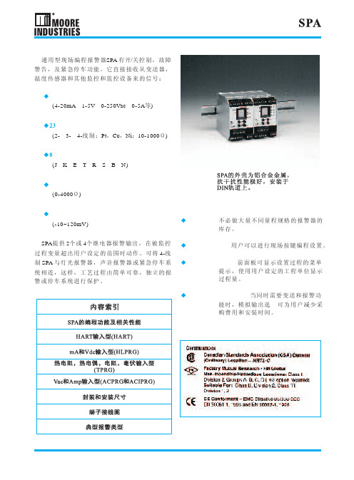
距1V)
-DPDT 双刀双掷继电器, 5A@250Vac, 50/60Hz, 非 感 性 负 载 (仅 限 式继电器, 0.5A@117Vac或 2A @28Vdc(仅 限 于 1 PGR和2PGR输 出 型)
选 型 格 式 : 型 号/输 入/输 出/电 源/选 项[封 装] 例 :SPA/HLPRG/4PRG/U/-AO[DIN] SPA/HLPRG/2PRG/U/-AO-DPDT[DIN]
型号
SPA
输入
HART 直接接收来自 带 HART 协 议 液位等变送器 的 HART 数 字 协议信号
输出
2PRG双继电器 继 电 器#1用 作HART设 备 故 障 报 警 ; 继 电 器 #2 用 量报警 4PRG四继电器 继 电 器# 1、#2同 上 ; 继 电 器#3、#4都 用 作 过 程 变量报警 各过程变量报警继电器可 独立组态: 高/低 报 警 方 式 ; 常 开 /常 闭 ; 故 障 安 全/非 故 障 安 全 ; 自 动 复 位/人 工 复 位 (继 电 器 缺 省 为 单 刀 双 掷 [SPDT],5A250Vac, 50/60Hz, 非 感 性 负 载) 注:故障安全状态是指 继电器在非报警状态下 励磁,而在报警状态或 掉电时非励磁 U
现场编程电流/电压、热电阻/热电偶、HART报警设定器 描 述 通 用 型 现 场 编 程 报 警 器SPA 有 开/关 控 制 , 故 障
警告,及紧急停车功能。它直接接收从变送器, 温度传感器和其他监控和监控设备来的信号: ◆ 电流和电压信号 (4-20mA,1-5V,0-250Vac,0-5A等) ◆23种热电阻 (2-,3-,4-线 制 ;Pt,Cu,Ni;10-1000Ω) ◆8种热电偶 (J,K,E,T,R,S,B,N) ◆ 电阻和变阻器 (0-4000Ω) ◆ 直接毫伏输入 (-10~120mV)
- 1、下载文档前请自行甄别文档内容的完整性,平台不提供额外的编辑、内容补充、找答案等附加服务。
- 2、"仅部分预览"的文档,不可在线预览部分如存在完整性等问题,可反馈申请退款(可完整预览的文档不适用该条件!)。
- 3、如文档侵犯您的权益,请联系客服反馈,我们会尽快为您处理(人工客服工作时间:9:00-18:30)。
Tanenbaum, Modern Operating Systems 3 e, (c) 2008 Prentice-Hall, Inc. All rights reserved. 0-13-6006639
Physical Memory Management (2)
Linux Utility Programs (2)
Figure 10-2. A few of the common Linux utility programs required by POSIX.
Tanenbaum, Modern Operating Systems 3 e, (c) 2008 Prentice-Hall, Inc. All rights reserved. 0-13-6006639
Figure 10-15. Linux main memory representation.
Tanenbaum, Modern Operating Systems 3 e, (c) 2008 Prentice-Hall, Inc. All rights reserved. 0-13-6006639
System call state • File descriptor table • Accounting • Kernel stack • Miscellaneous
Tanenbaum, Modern Operating Systems 3 e, (c) 2008 Prentice-Hall, Inc. All rights reserved. 0-13-6006639
Implementation of Processes and Threads
Categories of information in the process descriptor:
• Scheduling parameters • Memory image • Signals • Machine registers
Interfaces to Linux
Figure 10-1. The layers in a Linux system.
Tanenbaum, Modern Operating Systems 3 e, (c) 2008 Prentice-Hall, Inc. All rights reserved. 0-13-6006639
Process Management System Calls in Linux
Figure 10-6. Some system calls relating to processes.
Tanenbaum, Modern Operating Systems 3 e, (c) 2008 Prentice-Hall, Inc. All rights reserved. 0-13-6006639
Signals in Linux (1)
Figure 10-5. The signals required by POSIX.
Tanenbaum, Modern Operating Systems 3 e, (c) 2008 Prentice-Hall, Inc. All rights reserved. 0-13-6006639
A Simple Linux Shell
Figure 10-7. A highly simplified shell.
Tanenbaum, Modern Operating Systems 3 e, (c) 2008 Prentice-Hall, Inc. All rights reserved. 0-13-6006639
Processes in Linux
Figure 10-4. Process creation in Linux.
Tanenbaum, Modern Operating Systems 3 e, (c) 2008 Prentice-Hall, Inc. All rights reserved. 0-13-6006639
Networking (1)
Figure 10-19. The uses of sockets for networking.
Tanenbaum, Modern Operating Systems 3 e, (c) 2008 Prentice-Hall, Inc. All rights reserved. 0-13-6006639
Linux Utility Programs (1)
Categories of utility programs:
• File and directory manipulation commands. • Filters. • Program development tools, such as editors and
Kernel Structure
Figure 10-3. Structure of the Linux kernel
Tanenbaum, Modern Operating Systems 3 e, (c) 2008 Prentice-Hall, Inc. All rights reserved. 0-13-6006639
compilers. • Text processing. • System administration.
• Miscellaneous.
Tanenbaum, Modern Operating Systems 3 e, (c) 2008 Prentice-Hall, Inc. All rights reserved. 0-13-6006639
Networking (2)
Booting Linux
Figure 10-11. The sequence of processes used to boot some Linux systems.
Tanenbaum, Modern Operating Systems 3 e, (c) 2008 Prentice-Hall, Inc. All rights reserved. 0-13-6006639
Memory Management in Linux (2)
Figure 10-13. Two processes can share a mapped file.
Tanenbaum, Modern Operating Systems 3 e, (c) 2008 Prentice-Hall, Inc. All rights reserved. 0-13-6006639
Scheduling in Linux (2)
Figure 10-10. Illustration of Linux runqueue and priority arrays.
Tanenbaum, Modern Operating Systems 3 e, (c) 2008 Prentice-Hall, Inc. All rights reserved. 0-13-6006639
Scheduling in Linux (1)
Three classes of threads for scheduling purposes:
• Real-time FIFO. • Real-time round robin. • Timesharing.
Tanenbaum, Modern Operating Systems 3 e, (c) 2008 Prentice-Hall, Inc. All rights reserved. 0-13-6006639
The Clone System Call
Figure 10-9. Bits in the sharing_flags bitmap.
Tanenbaum, Modern Operating Systems 3 e, (c) 2008 Prentice-Hall, Inc. All rights reserved. 0-13-6006639
The Page Replacement Algorithm
Figure 10-18. Page states considered in the page frame replacement algorithm.
Tanenbaum, Modern Operating Systems 3 e, (c) 2008 Prentice-Hall, Inc. All rights reserved. 0-13-6006639
Memory Management System Calls in Linux
Figure 10-14. Some system calls relating to memory management.
Tanenbaum, Modern Operating Systems 3 e, (c) 2008 Prentice-Hall, Inc. All rights reserved. 0-13-6006639
Physical Memory Management (1)
Linux distinguishes between three memory zones:
• ZONE_DMA - pages that can be used for DMA operations.
• ZONE_NORMAL - normal, regularly mapped pages. • ZONE_HIGHMEM - pages with high-memory
Physical Memory Management (3)
Figure 10-16. Linux uses four-level page tables.
Tanenbaum, Modern Operating Systems 3 e, (c) 2008 Prentice-Hall, Inc. All rights reserved. 0-13-6006639
