美国博雷(BRAY)VCB F系列 2通3通法兰式球阀
博力谋球阀CCV

连接 Kvs[m3/h] DN[mm] 二通
螺纹连接
法兰连接 PN16
0.63 1.0 1.6 2.5 4.0 4.0 6.3 6.3 10.0 10.0 16.0 16.0 25.0 25.0 40.0 63 100 140 230 320
15
15
15
15
15
20
20
25
25
32
32
40
40
50
50
安装、水流方向和调试
52
安装注意事项
53
调试、维护和工程设计的注意事项
54
V9.0.10.2014 • 资料如有改动,恕不另行通知
2
产品概览
控制球阀和用于调节控制的角行程执行器
kv
控制球阀的流量特性
流量特性:等百分比
Y
额定压力: 三通, 4140kPa (DN15...25), 2760kPa (DN32...50) 二通, 2500kPa (DN15...50), 1600kPa (DN65...150)
热
性
-线
性
特
出
输
热
的
际
实
分
理想等百
比 阀 门特性
流量
阀门开度
100%
水系统控制的理想输出特性
100%
性 特 出
传统球阀 流 量 特 性
实际的 热 输
流量
阀门开度
100%
传统球阀流量特性
搏力谋赋予了球阀“控制”能力
100%
盘管 热 输
性
特
出
性
线
一
性
特
出
输
热
的
Bray92-93气动执行器
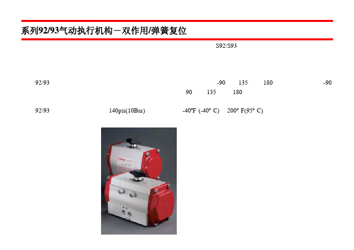
结合了独特的风格,简洁的设计和实用性,美国博雷控制公司提供新的 S92/S93 系列的高性能,优质的气动执行机 构来适应当今市场的需求。 先进的技术,精密的加工制造,经济实用,节省空间。而且,模块设计,可直接安装其他博雷配件,增加其效率和 经济性。 系列 92/93 气动执行机构是齿条齿轮,双活塞设计。分两种型号:双作用-90 度、135 度和 180 旋转度;弹簧复位-90 度旋转。两者能理想的驱动球阀、蝶阀或旋塞阀,并应用于 90 度,135 度和 180 度旋转。手轮和输出轴产生的偏 心负荷正好由低摩擦系数醇缩醛轴承来承受。 系列 92/93 的最高工作压力可达 140psi(10Bar);温度范围从-40ºF (-40º C)至 200º F(95º C)。如需更高或更低的工作 温度,请问博雷厂家或经销商咨询。
数量
说 明
1
外壳
2
活塞
1
齿轮
2
端盖
最大 12 弹簧组合
1
上轴承
1
下轴承
1
保持环
1
尼龙垫圈
2 醇缩醛轴承垫片
2
醇缩醛导环
2
行程限制螺母
2 可调行程限制螺丝
2 行程限制 O形环
1
醇缩醛衬套
1
行程限位
8
六角螺丝
8
垫圈
2
活塞 O形环
2
端盖 O形环
1
上轴 O形环
1
下轴 O形环
1
开度指示
1
开度指示器
标准材料 外壳:挤压铝,经氧化处理
注:不可超过以上最大调节范围
上图所示为系列 93 弹簧复位的组件 *系列 92 双作用不包 含弹簧组件
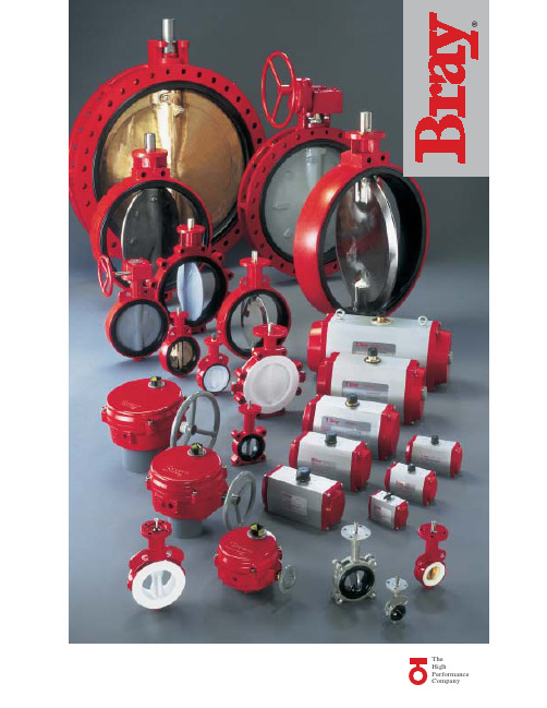
美国博雷(BRAY)蝶阀 执行机构 博雷阀门产品系列及配件
70系列电动执行机构亦可提供应 用于流量控制阀门的精确定位。这 一系列阀门的配置为可接收模拟输 入信号的电路板或串行通讯总线, 如DeviceNet。
手动执行器
S1手柄及齿盘
博雷提供两种手柄用于 开关和调节,一种用于1"12"(25mm-300mm)弹性阀 座阀门,另一种用于2-1/2" -8"(65mm-200mm)高压阀 门的大扭拒手柄。90°回转 手柄具有弹簧锁定功能和 指示阀板位置的方向指示 针。同时提供带螺栓的阀 板。对于弹性阀座齿盘有 10个位置是标准的。对于 高压阀齿盘有八个位置是 标准的。两种阀门都配有 限位开关以防阀门旋转过度。另外 提供非限位位置板,180°槽板,一 个记忆限位及一个2"方形螺帽。
博雷忠实服务于客户。我们的 员工训练有素,对博雷各类产品了 如指掌,给予客户一对一的服务。 此外,博雷还有经验丰富的经销商, 在世界范围内为我们的客户提供优 质服务。
根据博雷标准设计的产品系列 具有极高的兼容性、经济性,性能 优异,为现代工业的应用提供了优 质的选择。
弹性衬胶阀门 博雷提供的全系列弹性 衬胶蝶阀应用广泛,性能 可靠,经久耐用。 其 独 特 性 在 于 , 我 们 的 阀门能够与绝大多数法兰 标准兼容。因此,同一种阀门可 适应不同市场的需求。另一个特 性是我们的舌槽式阀座设计可以 完全阻隔流体渗入阀体和阀杆。 大多数标准阀体使用聚酯涂层确 保了良好的防腐性能并且阀门表 面不易受到磨损。博雷阀门在颈 部均有加长设计,与管线至少有 50mm的距离。阀门顶盘连接法兰 符合ISO5211标准,可直接连接手 柄或执行机构。阀门有对夹式、 支耳式和双法兰式,连接方式符 合ANSI125/150法兰标准。
Belimo B215HT186 双向特殊控制阀说明书

B215HT1862-way, Characterized Control Valve, StainlessSteel Ball and StemType overviewType DNB215HT18615 Technical dataFunctional data Valve size [mm]0.5" [15]Fluid high temperature hot water/low pressuresteam, up to 60% glycolFluid Temp Range (water)60...266°F [16...130°C]Fluid Temp Range (steam)250°F [120°C]Body Pressure Rating600 psiClose-off pressure ∆ps200 psiFlow characteristic equal percentagePipe connection Internal threadNPT (female)Servicing maintenance-freeMax Differential Pressure (Steam)15 psiFlow Pattern2-wayLeakage rate0%Controllable flow range75°Cv 1.86Maximum Inlet Pressure (Steam)15 psiMaterials Valve body Nickel-plated brass (DZR) P-CuZn35Pb2Stem stainless steelStem seal Vition O-ringSeat ETFECharacterized disc ETFEO-ring EPDM (lubricated)Ball stainless steelSuitable actuators Non Fail-Safe TRLRB(X)Spring TFRB(X)•Safety notesWARNING: This product can expose you to lead which is known to the State of California tocause cancer and reproductive harm. For more information go to B215HT186ApplicationProduct featuresThis valve is typically used in air handling units on heating or cooling coils, and fan coil unit heating or cooling coils. Some other common applications include unit ventilators, VAV box re-heat coils and bypass loops. This valve is suitable for use in a hydronic system with variable flow.This valve is designed to fit in compact areas where on/off, floating point and modulating control is required using 24 VAC.Flow/Mounting detailsDimensionsTypeDN Weight B215HT186150.61 lb [0.28 kg]TRAB C D E F 4.2" [106]3.3" [85]5.4" [137]4.9" [125]1.5" [39]1.5" [39]LRB, LRXAB C D E F H1H28.3" [211]3.3" [85]5.8" [147]5.3" [134]1.3" [33]1.3" [33]1.2" [30]0.6" [15]B215HT186DimensionsTFRB, TFRXA B C D E F7.3" [185] 3.3" [85] 5.8" [147] 5.3" [134] 1.5" [39] 1.5" [39]LRB24-3On/Off, Floating point, Non fail-safe, 24 VFootnotesTechnical dataElectrical dataNominal voltageAC/DC 24 V Nominal voltage frequency 50/60 HzNominal voltage rangeAC 19.2...28.8 V / DC 21.6...28.8 V Power consumption in operation 1.5 W Power consumption in rest position 0.2 W Transformer sizing 2.5 VAElectrical Connection 18 GA plenum cable, 3 ft [1 m], with 1/2" NPT conduit connectorOverload Protection electronic thoughout 0...90° rotation Electrical Protectionactuators are double insulated Functional dataDirection of motion motor selectable with switch 0/1Manual override external push button Angle of rotation 90°Angle of rotation note adjustable with mechanical stop Running Time (Motor)90 s / 90°Noise level, motor 35 dB(A)Position indicationMechanical, pluggable Safety dataPower source ULClass 2 Supply Degree of protection IEC/EN IP54Degree of protection NEMA/UL NEMA 2Enclosure UL Enclosure Type 2Agency Listing cULus acc. to UL60730-1A/-2-14, CAN/CSA E60730-1:02, CE acc. to 2014/30/EU Quality Standard ISO 9001UL 2043 CompliantSuitable for use in air plenums per Section 300.22(C) of the NEC and Section 602 of the IMCAmbient humidity Max. 95% RH, non-condensing Ambient temperature -22...122°F [-30...50°C]Storage temperature -40...176°F [-40...80°C]Servicingmaintenance-free Weight Weight1.3 lb [0.59 kg]MaterialsHousing material Galvanized steel and plastic housing†Rated Impulse Voltage 800V, Type action 1.B, Control Pollution Degree 3.LRB24-3AccessoriesElectrical accessories Description TypeBattery backup system, for non-spring return models NSV24 USBattery, 12 V, 1.2 Ah (two required)NSV-BATAuxiliary switch 1x SPDT add-on S1AAuxiliary switch 2x SPDT add-on S2AFeedback potentiometer 140 Ω add-on, grey P140A GRFeedback potentiometer 1 kΩ add-on, grey P1000A GRFeedback potentiometer 10 kΩ add-on, grey P10000A GRFeedback potentiometer 2.8 kΩ add-on, grey P2800A GRFeedback potentiometer 500 Ω add-on, grey P500A GRFeedback potentiometer 5 kΩ add-on, grey P5000A GR Electrical installationINSTALLATION NOTESProvide overload protection and disconnect as required.Actuators may be connected in parallel. Power consumption and input impedance must beobserved.Actuators may also be powered by DC 24 V.Actuators Hot wire must be connected to the control board common. Only connect common toneg. (-) leg of control circuits. Terminal models (-T) have no-feedback.Actuators with plenum cable do not have numbers; use color codes instead.Meets cULus requirements without the need of an electrical ground connection.Warning! Live electrical components!During installation, testing, servicing and troubleshooting of this product, it may be necessaryto work with live electrical components. Have a qualified licensed electrician or other individualwho has been properly trained in handling live electrical components perform these tasks.Failure to follow all electrical safety precautions when exposed to live electrical componentscould result in death or serious injury.Wiring diagramsOn/Off Floating PointFloating Point - Triac Sink。
球阀
20
20
M36×2
25
25
24
M42×2
30
25
24
M52×2
38
SKH 38S 32 31251
32
32
M52×2
38
阀总 i
重量
长 L mm SW1 kg
69 9 22 0.35
69 12 22 0.35
69 12 22 0.35
73 12 27 0.5
85 14 30 0.65
96 17 41 1.5
成铭液压
高压球阀选型指导
OSJ
订货号示意:
球阀类型
见球阀各自说明
连接方式
见球阀各自说明
公称通径
见球阀各自说明
阀体材料
1 9SMnPb28K型钢 2 C35锻钢 3 ST52-3锻钢 4 不锈钢316Ti 5 铸钢 6 铸造不锈钢 7 黄铜 8 C22.8锻钢和圆钢 9 特种材料
球阀材料概述及应用
球体和阀杆材料
目录 球阀
球阀选型 BKH/SKH 高压碳钢直通球阀 RKH 不锈钢高压直通球阀 IK2/IK3 小通径不锈钢仪表球阀 BK3/SK3 三通高压球阀 3KH/4KH 高压多路球阀 HRKH 超高压球阀 FSKH 带活法兰中高压球阀(德标法兰) BKHU 板式高压球阀 PV2/PV3 紧凑型 SAE 二通/三通板式球阀 BKH/SKH/RKH SAE 法兰式碳钢/不锈钢球阀 FCKH 大通径高压球阀 手柄 经济型低压铜球阀 KH 中低压不锈钢球阀 FKH 德标法兰式球阀 MD 不锈钢三通低压法兰式球阀 定位开关
5
1/8〞NPT -
BKH 1/4NPT 06 11251 6
6
衬里旋塞阀-X43F衬里旋塞阀
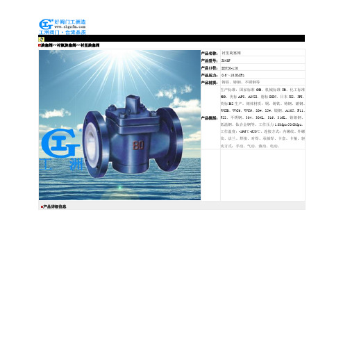
旋塞阀>>衬氟旋塞阀>>衬里旋塞阀产品详细信息球阀系列价格供用户或设计院工程项目做预算一、阀门的选型步骤1.明确阀门在设备或装置中的用途,确定阀门的工作条件:适用介质、工作压力、工作温度等等。
2.确定与阀门连接管道的公称通径和连接方式:法兰、螺纹、焊接等。
3.确定操作阀门的方式:手动、电动、电磁、气动或液动、电气联动或电液联动等。
4.根据管线输送的介质、工作压力、工作温度确定所选阀门的壳体和内件的材料:灰铸铁、可锻铸铁、球墨铸铁、碳素钢、合金钢、不锈耐酸钢、铜合金等。
5.确定阀门的型式:闸阀、截止阀、球阀、蝶阀、节流阀、安全阀、减压阀、蒸汽疏水阀、等。
6.确定阀门的参数:对于自动阀门,根据不同需要先确定允许流阻、排放能力、背压等,再确定管道的公称通径和阀座孔的直径。
7.确定所选用阀门的几何参数:结构长度、法兰连接形式及尺寸、开启和关闭后阀门高度方向的尺寸、连接的螺栓孔尺寸和数量、整个阀门外型尺寸等。
8.利用现有的资料:阀门产品目录、阀门产品样本等选型适当的阀门产品。
二、阀门的选型依据1.所选用阀门的用途、使用工况条件和操纵控制方式。
2.工作介质的性质:工作压力、工作温度、腐蚀性能,是否含有固体颗粒,介质是否有毒,是否是易燃、易爆介质,介质的黏度等等。
3.对阀门流体特性的要求:流阻、排放能力、流量特性、密封等级等等。
4.安装尺寸和外形尺寸要求:公称通径、与管道的连接方式和连接尺寸、外形尺寸或重量限制等。
⑤对阀门产品的可靠性、使用寿命和电动装置的防爆性能等的附加要求。
(在选定参数时应注意:如果阀门要用于控制目的,必须确定如下额外参数:操作方法、最大和最小流量要求、正常流动的压力降、关闭时的压力降、阀门的最大和最小进口压力。
)根据上述选型阀门的依据和步骤,合理、正确地选型阀门时还必须对各种类型阀门的内部结构进行详细了解,以便能对优先选用的阀门做出正确的抉择。
管道的最终控制是阀门。
汽车英语缩写大全

汽车英语缩写大全进口汽车维修技术缩略语词典*C Degrees Celsius摄氏度*F Degrees Fahrenheit 华氏度*D*Drive 驱动,驾驶,行驶,行车*N* Neutral Position 空档*P**PARK*Position P档,停车档*P* *PARK*Position P(驻车)档位置O2 Oxygen 氧气2WD Two—Wheel Drive 两轮驱动4WD Four-Wheel Drive四轮驱动4WS Four-Wheel Steering四轮转向AA A—post, A—pillar A柱A Amperes 安培, 电流A *Amper *Ammeter *Advance *安培*电流表*提前A.I。
R。
Air Injection Reactor 空气喷射反作用器A.M。
Above-Mentioned 上述的A/C Air Conditioning空调A/C A/C Amplifie 空调放大器A/C CLTCH。
A/C Clutch空调离合器A/CL Air Cleaner 空气滤清器A/CL-BM Air Cleaner Bimetal Sensor空气滤清器双金属传感器A/CL-CWM Air Cleaner Cold Weather Modulator 空气滤清器低温调节器A/CL—DV Air Cleaner Duct Valve Vacuum Motor 空气滤清器导管阀真空马达A/CL—TSOV Air Cleaner Temperature Sensor Override Valve空气滤清器温度传感器超压阀A/CL-VCD Air Cleaner Vacuum Control Delay 空气滤清器真空延迟控制A/CL-VCV Air Cleaner Vacuum Control Valve 空气滤清器真空控制阀A/CL—VM Air Cleaner Vacuum Motor空气滤清器真空马达A/F Air-Fuel Ratio空燃比A/T Automatic Transaxle Or Transmission 自动变速箱AA Automobile Association (UK)英国汽车协会AAA American Automobile Association美国汽车协会AAC Auxiliary Air Control辅助空气控制AAC Automatic Amplitude Control自动振幅控制AACV Auxiliary Air Control Valve辅助空气控制阀AAD Auxiliary Air Control Device 辅助空气装置AAE America Association of Engineers 美国工程师协会AAMVM American Association of Motor Vehicle Manufacturers美国汽车制造者协会AAP Auxiliary Accelerator Pump 辅助加速器泵AAP Auxiliary Accelerating Pump辅助加速泵AAP Ambient Absolute Pressure外界绝对压力AAS Aspirator Air System吸气(真空)控制系统AAS Auto Adjust Suspension 自动调节悬挂AAS Air Adjust Screw空气调整螺丝AAS American Astronautical Society 美国宇宙航行学会AAS Air Adjust Screw空气调节螺钉AASHTO American Association of State Highways and Transportation Officials 美国各州公路及运输公务员协会AAV Anti Afterburn Valve 防止后燃阀AB Air Bleed 空气泄放ABA Air Bleed Actuator空气排放执行器(电磁阀)ABCV Air Bleed Control Valve空气泄放控制阀ABDC After Bottom Dead Center在下止点后ABG Alcohol Blended Gasoline掺酒精的汽油ABN Airborne Noise 空气传播的噪音ABP Air Brake Proportioing (valves) 空气制动比例分配(阀)ABRS Air Bag Restraint System 安全气囊ABS Altitude Barometric Switch 高度(海拔)气压开关ABS Anti—Lock Brake System 防锁刹车系统,防抱刹车系统,反锁定刹车系统ABS American Bureau of Standards 美国标准局Abs Absolute 绝对的ABS Visc Absolute Viscosity绝对粘度ABSV Air Bypass Solenoid Valve空气旁通电磁阀ABV *Anti Backfire Valve *Air Bypass Valve *防止逆火阀*空气旁通阀ABV Air Bypass Valve 空气旁通阀ABV Anti-Backfire Valve 防回火阀AC Air Condition 空调AC Alternating Current Generator 交流发电机AC *Alternating Current *After Contro *交流电*后段调整式AC AC Auxiliary Fan Relay空调辅助风扇继电器AC AC Compressor Safety Switch空调压缩机安全开关AC AC Condenser Blower Motor Relay空调冷凝器鼓风马达继电器AC AC Control Unit 空调电脑盒AC AC Diode空调二极管AC AC Evaporator Motor Relay空调蒸发马达继电器AC AC Evaporator Pump Line Fuse空调蒸发泵保险丝AC AC High Pressure Safety Switch空调高压安全开关AC AC Idle Boost Valve 空调怠速加压阀AC Alternating Current 交流电AC Ante Christum 公元前AC Accumulator 蓄电池,储压器AC Acid酸AC Analogue Computer模拟计算机AC Automatic Control 自动控制AC Air—Cooled 空冷AC Armored Car 装甲汽车AC Adaptive Control自适应调节AC Aerodynamic Center 空气动力中心AC Air Cooling 风冷,空气冷却,气冷AC Air Cycle 空气循环AC Automatic Clutch自动离合器ACC A/C Clutch Compressor 空调压缩机ACC Air Conditioning Clutch 空调离合器ACC Air Conditioning Clutch Switch空调离合器开关ACC Automatic Climate Control电脑恒温控制ACC *Accessary *Altitude Compensation Carb *附件*高度补偿化油器Accel Accelerator 油门,加速踏板,加速泵ACCS A/C Clutch Cycling Switch 空调离合器循环开关ACCS Air Conditoning Cycling Switch 空调循环开关Accum Accumulator 蓄压器ACCWM Air Cleaner Cold Weather Modulator 空气滤清器低温调节器Accy Accessory 附件ACD Auxiliary Control Device 辅助控制装置ACD Air Conditioning Demand 空调作用指令ACD Air Conditioning Demand Switch 空调需求开关ACDV Air Cleaner Diverter Valve 空气滤清器分流阀ACE Air Conditioning Equipment空气调节设备ACE Automatic Check Equipment 自动检测设备ACE Automatic Computing Equipment 自动计算装置ACE Air Conditioning Equipment 空调设备ACG Alternating Current Generator交流发电机ACG Automatic Control Gear自动控制变速ACID TEST CYC—LE Acceleration,Cruise, Idle,Deceleration Test Cycle加速.稳速。
MASCOT产品选型样本

201 支架 202 气缸 210 调节螺钉 211 执行机构推杆 213 行程刻度牌 225 活塞 227 弹簧扣 228 执行机构推杆垫片 229 弹簧 248 调节螺钉垫片 249 阀杆夹 253 支架衬套 256 固定环 271 活塞O形环 272 活塞推杆O形环 274 支架O形环 275 执行机构推杆O形环 348 执行机构推杆锁紧螺母
锻造
锻造车间的能力包括落锤锻造和自由锻造直径最大至1000mm的各种标准材料 和特殊材料,制造成阀盖、法兰、阀塞和阀座环。
配合
诸如大型加工中心和数控机床(CNC)等扩展 设备能够生产各种不同尺寸的阀组件。
涂装
可以满足各种不同的涂装要求,比如标准涂装、用于海上服务的厚涂层涂装,以及用 于高温场合的涂装要求。
MASCOT Industrial 15A Randor Street Campbellfield, Victoria 3061 Australia
Tel: +61 3 9357 6555 | Fax: +61 3 9357 6566 Email: sales@ | Web: 本手册仅供信息参考,我们会努力确保资料的准确性和所提供技术规格的精确度, 但手册内容不作为对 于产品本身的解释或担保。MASCOT Industrial保留对产品设计的更改或改进的权力,本手册中产品信息 和技术规格如有变更,恕不另行通知。MASCOT Industrial对产品的选型,使用和维护不予负责。产品的
高端技术 紧密关断
澳大利亚的制造能力
高可靠性 值得信赖
Page 2
源自澳大利亚的制造能力
MASCOT公司所具有的源自澳大利亚的制造能力包括针对困难工况,应用多种 材料和特殊设计,制造压力等级为ASME CL150至CL4500,尺寸范围由0.5” 至36”的球阀以及2.0”至48”的旋转阀(蝶阀、V形球阀、偏心旋塞阀)。 澳大利亚企业利用供应商合作关系来完成铸件的生产和阀组件的加工 这使加工车间的工作量更具弹性并且大大减少了生产交付周期。 与合作伙伴迄今二十年的合作使MASCOT公司在高品质和及时交付表现上取得 了有证明的良好记录。
贝利摩(Belimo)B210铝金属阀门数据表说明书

B210•ApplicationStainless Steel Ball and StemTechnical dataFunctional dataValve Size 0.5" [15]Fluidchilled or hot water, up to 60% glycol Fluid Temp Range (water)0...250°F [-18...120°C]Body Pressure Rating 600 psi Close-off pressure ∆ps 200 psiFlow characteristic equal percentage Servicing maintenance-free Flow Pattern 2-way Leakage rate0% for A – AB Controllable flow range 75°Cv1.2 Body pressure rating note 600 psiCv Flow RatingA-port: as stated in chart B-port: 70% of A – AB Cv MaterialsValve body Nickel-plated brass body Stem seal EPDM (lubricated)SeatPTFEPipe connection NPT female ends O-ring EPDM (lubricated)Ballstainless steel Suitable actuatorsNon-SpringTR LRB(X)NRSafety notesWARNING: This product can expose you to lead which is known to the State of California to cause cancer and reproductive harm. For more information go to Product featuresThis valve is typically used in air handling units on heating or cooling coils, and fan coil unit heating or cooling coils. Some other common applications include Unit Ventilators, VAV box re-heat coils and bypass loops. This valve is suitable for use in a hydronic system with variable flow.Flow/Mounting detailsB210 DimensionsDimensional drawingsLRB, LRXA B C D E F H1H29.4" [239] 2.4" [60] 5.2" [132] 4.6" [117] 1.3" [33] 1.3" [33] 1.2" [30] 1.1" [28]TRA B C D E F3.7" [95] 2.4" [60]4.8" [122] 4.2" [107] 1.3" [33] 1.3" [33]TFRB, TFRXA B C D E F6.6" [167] 2.4" [60] 4.9" [124] 4.3" [110] 1.5" [39] 1.5" [39]LFA B C D E F7.9" [200] 2.4" [60] 5.7" [146] 5.1" [129] 1.8" [46] 1.8" [46]ARB N4, ARX N4, NRB N4, NRX N4A B C D E F11.4" [289] 2.4" [60]7.7" [196]7.0" [179] 3.1" [80] 3.1" [80]A B C D E F7.9" [200] 2.4" [60] 5.7" [146] 5.1" [129] 1.8" [46] 1.8" [46]B210TFRB, TFRXA B C D E F6.6" [167] 2.4" [60] 4.9" [124] 4.3" [110] 1.5" [39] 1.5" [39]ARB N4, ARX N4, NRB N4, NRX N4A B C D E F11.4" [289] 2.4" [60]7.7" [196]7.0" [179] 3.1" [80] 3.1" [80]LRB24-3-S•••••On/Off, Floating Point, Non-Spring Return, 24 VTechnical dataElectrical dataNominal voltageAC/DC 24 V Nominal voltage frequency 50/60 Hz Power consumption in operation 1.5 W Power consumption in rest position 0.2 WTransformer sizing 2.5 VA (class 2 power source)Auxiliary switch1 x SPDT, 3 A resistive (0.5 A inductive) @ AC 250 V, adjustable 0...100%Switching capacity auxiliary switch 3 A resistive (0.5 A inductive) @ AC 250 V Electrical Connection 18 GA plenum cable, 3 ft [1 m], with 1/2" conduit connectorOverload Protectionelectronic thoughout 0...90° rotation Functional dataInput Impedance 600 ΩDirection of motion motor selectable with switch 0/1Manual override external push button Angle of rotation 90°Angle of rotation note adjustable with mechanical stop Running Time (Motor)90 s Noise level, motor 35 dB(A)Position indicationMechanically, pluggable Safety dataDegree of protection IEC/EN IP54Degree of protection NEMA/UL NEMA 2 UL Enclosure Type 2Agency ListingcULus acc. to UL60730-1A/-2-14, CAN/CSAE60730-1:02, CE acc. to 2014/30/EU and 2014/35/EU; Listed to UL 2043 - suitable for use in air plenums per Section 300.22(c) of the NEC and Section 602.2 of the IMC Quality Standard ISO 9001Ambient temperature -22...122°F [-30...50°C]Storage temperature -40...176°F [-40...80°C]Ambient humidity max. 95% r.H., non-condensing Servicingmaintenance-free WeightWeight1.4 lb [0.60 kg]Safety notesWeather shield - PC w/ foam seal 16x8-3/8x4" (LxWxD).Battery Back Up System for SY(7~10)-110120 to 24 VAC, 40 VA transformer.12VDC 1.2 AH battery (2 required).PC Tool computer programming interface, serial port.LRB24-3-S Electrical installationINSTALLATION NOTESProvide overload protection and disconnect as required.Actuators may be connected in parallel. Power consumption and input impedance must be observed.Actuators may also be powered by 24 VDC.Actuators Hot wire must be connected to the control board common. Only connect common to neg. (-) legof control circuits. Terminal models (-T) have no-feedback.Actuators with plenum cable do not have numbers; use color codes instead.One built-in auxiliary switch (1x SPDT), for end position indication, interlock control, fan startup, etc.Apply only AC line voltage or only UL-Class 2 voltage to the terminals of auxiliary switches. Mixed orcombined operation of line voltage/safety extra low voltage is not allowed.Meets cULus requirements without the need of an electrical ground connection.Warning! Live Electrical Components!During installation, testing, servicing and troubleshooting of this product, it may be necessary to workwith live electrical components. Have a qualified licensed electrician or other individual who has beenproperly trained in handling live electrical components perform these tasks. Failure to follow all electricalsafety precautions when exposed to live electrical components could result in death or serious injury.On/Off Floating PointFloating Point - Triac Source Floating Point - Triac SinkAuxiliary Switches。
美国卡麦隆管线球阀产品样本

C O O P E R C A M E R O N V A LV ES1FULLY WELDED BALL VALVESFULLY WELDED BALL VALVES Features and Benefits2, 3, 4 & 5In-line Sphere Launcher 6Accessories7HOW TO ORDER Standards, Specifications and Materials 8 & 9DIMENSION TABLES ASME/ANSI Class 150 through 2500 (PN 20 through PN 420)Full and Reduced Port Valves 10 through 22API PRESSURE CLASS 2000, 3000 & 5000 psiFull and Reduced Port Valves23, 24 & 25DIMENSION TABLES Actuator Mounting Information26, 27 & 28PIPING INFORMATION TABLE29TERMS AND CONDITIONS30 & 31TRADEMARK INFORMATION32TABLE OF CONTENTSTC145512/04 NP-5MP卡 麦 隆 全 焊 接 球 阀目 录全焊接球阀特点和优点管线清管球发送器附件如何购买卡麦隆球阀标准、规范和材料尺寸表全通径和缩径球阀全通径和缩径球阀尺寸表执行机构安装信息管子尺寸表商务条款和条件商标信息CO O P E R C A M E R O N V A LV E S2Engineered for heavy duty, maintenance free performance, the Cameron Fully Welded Ball Valve is commonly selected for a number of applications, including:One of the most trusted valves in the petroleum industry, itcombines the strength of forged components with a lightweight and compact spherical design.Cameron Fully Welded Ball Valves satisfy ASME/ANSI 150 through 2500 (PN 20 through PN 420) and API 2000 through10,000 standards. Made of forged steel to assure uniform fine grain structure and toughness, they may be specified in sizes from 2 in. to 56 in. (50 mm to 1400 mm).FEATURES AND BENEFITS•Gas transmission •NGL plants •Products pipeline •NGL pipeline •Measurements skids •Compressor stations •Dehydration systems •CO services 2•Gas separation systems •Offshore •Natural gas storage •Subsea•Dryer serviceTC145512/04 NP-5MFULLY WELDED BALL VALVES卡 麦 隆 全 焊 接 球 阀特 点 和 优 点石油工业中最值得信赖的阀门, 综合了轻型锻件的强度和紧凑式球形设计。
飞斯托检压式阀门VBNF-LBA产品简介说明书
Piloted check valve VBNFPiloted check valve VBNFCharacteristicsAtaglanceThe check valve VBNF-LBA is a valve with piloted non-return function and manual exhaust function.• Minimal height• High flow rate• Can be rotated horizontally through 360° when mounted• Actuation direction can be changed by converting the housingDiagrams Further information → vbnfThe diagrams shown in this document are also available online. These can be used to display precise values.DesignInline[L]L-shape[C]Universal actuation direction possible by converting the housing [1]:• Press thrust ring [2] into the housing for a positive fit• Insert hollow bolt [3] into the opening• Slide sealing ring OK [4] over the thread of the hollow boltNon-returnfunction[B]Piloted non-return functionThe piloted non-return function can be used for a brief intermediate stop. If thereis a control signal, the exhaust air can escape. If there is no control signal, thevalve blocks the exhaust air of the drive and the drive stops briefly.Additionalfunction2[A]Exhaust function, manualA pneumatic drive can be manually exhausted by actuating the integrated manualexhaust function.2d/catalogue/...– 2023/12Piloted check valve VBNFType code32023/12 – d/catalogue/...Piloted check valve VBNFDatasheetFunction4d/catalogue/...– 2023/1252023/12 – d /catalogue/...Piloted check valve VBNFDatasheetStandardnominalflowrateqnNinflowcontroldirectionat6→5 barasafunctionofspindlerotationsnStandardflowrateqninflowcontroldirectionat6→0 barasafunctionofspindlerotationsnMinimumpilotpressurep21asafunctionofoperatingpressurep1Piloted check valve VBNFDimensions6d/catalogue/...– 2023/12Piloted check valve VBNF Dimensions7 2023/12 – d/catalogue/...Piloted check valve VBNFDimensions8d/catalogue/...– 2023/12Piloted check valve VBNF Ordering dataOrderingdata(inline)9 2023/12 – d/catalogue/...Piloted check valve VBNFAccessories10d/catalogue/...– 2023/12。
霍尼韦尔(HONEYWELL)VBF2,VBF3系列阀门(英文)
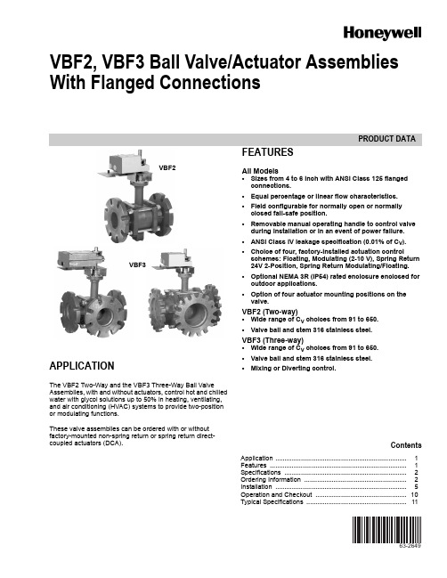
PRODUCT DATA63-2649VBF2, VBF3 Ball Valve/Actuator Assemblies With Flanged ConnectionsAPPLICATIONThe VBF2 Two-Way and the VBF3 Three-Way Ball Valve Assemblies, with and without actuators, control hot and chilled water with glycol solutions up to 50% in heating, ventilating, and air conditioning (HVAC) systems to provide two-position or modulating functions.These valve assemblies can be ordered with or without factory-mounted non-spring return or spring return direct-coupled actuators (DCA).FEATURESAll Models•Sizes from 4 to 6 inch with ANSI Class 125 flanged connections.•Equal percentage or linear flow characteristics.•Field configurable for normally open or normally closed fail-safe position.•Removable manual operating handle to control valve during installation or in an event of power failure.•ANSI Class IV leakage specification (0.01% of C V ). •Choice of four, factory-installed actuation controlschemes: Floating, Modulating (2-10 V), Spring Return 24V 2-Position, Spring Return Modulating/Floating.•Optional NEMA 3R (IP54) rated enclosure enclosed for outdoor applications.•Option of four actuator mounting positions on the valve.VBF2 (Two-way)•Wide range of C V choices from 91 to 650.•Valve ball and stem 316 stainless steel.VBF3 (Three-way)•Wide range of C V choices from 91 to 650.•Valve ball and stem 316 stainless steel.•Mixing or Diverting control.VBF2VBF3ContentsApplication ........................................................................1Features ...........................................................................1Specifications ...................................................................2Ordering Information ........................................................2Installation ........................................................................5Operation and Checkout ..................................................10Typical Specifications . (11)VBF2, VBF3 BALL VALVE/ACTUATOR ASSEMBLIES WITH FLANGED CONNECTIONS62-26492ORDERING INFORMATIONWhen purchasing replacement and modernization products from your TRADELINE® wholesaler or distributor, refer to the TRADELINE® Catalog or price sheets for complete ordering number.If you have additional questions, need further information, or would like to comment on our products or services, please write or phone:1.Your local Honeywell Automation and Control Products Sales Office (check white pages of your phone directory).2.Honeywell Customer Care1885 Douglas Drive NorthMinneapolis, Minnesota 55422-4386In Canada—Honeywell Limited/Honeywell Limitée, 35 Dynamic Drive, Toronto, Ontario M1V 4Z9.International Sales and Service Offices in all principal cities of the world. Manufacturing in Australia, Canada, Finland, France, Germany, Japan, Mexico, Netherlands, Spain, Taiwan, United Kingdom, U.S.A.SPECIFICATIONSModels: See Table 2.Dimensions: See Fig. 1 and 2.Body Style: Two-way ball valve, straight-through flow, full or reduced port using patented flow control insert.Three-way ball valve, A-AB-B flow, full or reduced port using laser-milled stainless steel control ball.Combination ANSI 125/PN16 flanged connections.Body Size: 4 to 6 inch.Flow Capacity: See Table 1.Body Pressure Rating (maximum):240 psi (1655 kPa) at 250°F (121°C).Controlled Medium: Water or Glycol solutions up to 50%. Not suitable for combustible gases.Fluid Temperature Range: -22 to +250°F (-30 to +121°C).Maximum Differential Pressure: See Table 3.Flow Characteristics:Two-way:Equal Percentage.Linear with full port.Three-way:Port A to AB: Equal Percentage.Port B to AB: Linear.Mounting: Bolt holes conform to ANSI B16.1.Materials:Body: Cast Iron ASTM A395, 60-40-18Ball and Stem: 316 Stainless Steel.Stem Seals: EPDM O-Rings.Ball Seals: Teflon ™ SealsApprovals/Standards:Valves: ANSI Class IV close-off/leakage.Actuators: Non-Spring Return, Floating or Modulating UL/cUL.UL873 Plenum Rating, File No. E4436; Guide No. XAPX.CESpring Return 2-Position, 24 Vac or Floating/Modulating UL/cULUL873 Plenum Rating, File No. E4436; Guide No. XAPX.CE C-TICK Accessories:7981-200 replacement mounting kit for Honeywell direct cou-pled actuators. See Fig. 8.® Registered Trademark of the General Electric Company ™ Registered Trademark of E I DuPont de NemoursTable 1. Flanged Valves C V Values.aFor three-way valves onlyPipe Size C V DesignatorS TU12345674 in.91118152197254327a5 in.1441852403094006 in.208268346441577650VBF2, VBF3 BALL VALVE/ACTUATOR ASSEMBLIES WITH FLANGED CONNECTIONS362-2649Table 2. Model Selection.Application NotesRequired TorqueBoth Honeywell non-spring return and spring return direct coupled actuators can be utilized with the VBF2 and VBF3 valves. See Table 3, which lists the close-off pressure rating for the valves with the different torque actuators. Larger torque actuators may be used, but there is no increase in close-off pressure rating.Table 3. Close-off Pressure RatingsFlow CharacteristicsVBF2 Two-Way Ball Valves have:•an equal percentage flow characteristic.VBF3 Three-Way Ball Valves have:•between ports A and AB: an equal percentage flow characteristic.•between ports B and AB: a linear flow characteristic.Valve Fitting Body / FlowSizeC VT / PTrimEnclosureActuatorVB = valve, ballF = Flanged2 = 2 way3 = 3 wayinch S.I. metric J 4DN100K 5DN125L6DN150S C V Designator: See Table 1.T U 12345671 = ANSI Valve constructionS = Stainless Steel0 = no enclosureR = NEMA 3R enclosureX = no actuator A = NSR, Floating B = NSR, ModulatingC = SR, 2-Position, 24 VacD = SR, Floating/ModulatingVBF2AB1SAValve Size Actuator Torque88 in.-lb (10 Nm)175 in.-lb (20 Nm)175 in.-lb (20 Nm) 2-position 300 in.-lb (34 Nm) Close Off Pressure Rating (psid)4 in.70*1301301305 in.70*1301301306 in.70*70** This is the factory-installed actuator rating.VBF2, VBF3 BALL VALVE/ACTUATOR ASSEMBLIES WITH FLANGED CONNECTIONS62-26494Fig. 1. VBF2 dimensions in inches (millimeters).Fig. 2. VBF3 dimensions in inches (millimeters).VBF2, VBF3 BALL VALVE/ACTUATOR ASSEMBLIES WITH FLANGED CONNECTIONS562-2649INSTALLATIONWhen Installing this Product...1.Read these instructions carefully. Failure to follow them could damage the product or cause a hazardous condi-tion.2.Check ratings given in instructions and on the product to ensure the product is suitable for your application.3.Installer must be a trained, experienced service technician.4.After installation is complete, check out product operation as provided in these instructions.PreparationForeign particles like dirt and metal chips can damage the ball seals.For trouble-free operation of the product, goodinstallation practice must include initial system flushing, and chemical water treatment. Clean the linesupstream of particles larger than 1/16 inch diameter (welding slag, pipe scale, sand and other suspended particulate). Use of a 50 micron (or finer) system side stream filter is suggested. Remove all filters before flushing.Do not use boiler additives, solder flux and wettedmaterials which are petroleum based or contain mineral oil, hydrocarbons, or ethylene glycol acetate.Compounds which can be used, with minimum 50% water dilution, are diethylene glycol, ethylene glycol, and propylene glycol (antifreeze solutions).If installing these valves in an addition to, or retrofitting an existing building, do not assume that the fluid in the existing piping meets these criteria.Valve Installation LocationSelect a location where the valve and actuator will beaccessible, once installed. Allow sufficient space for servicing the valve and actuator. Clearance for valve installation is dependent on actuator size and the valve pipe size. See Figures 1 and 2 for valve body dimensions. Refer to actuator literature for actuator dimensions.1.Clean the lines upstream of the valve to remove particleslarger than 1/16 inch diameter (welding slag, pipe scale and other contaminants). Upstream installation of a 20 mesh strainer is recommended.2.Air should be eliminated from the system so the valvesremain full of fluid during operation.3.Straight sections of piping upstream and downstream of the valves are not necessary for proper operation.Reducing bushings or flanges may be attached directly to valves. Standard adapters are adequate for installation of flow control valves.4.Proceed with installation once the system specifics(expansion/contraction of the system and its medium as well as operating pressures) are within tolerances.5.Do not lift the valve by holding the stem.Mounting Valve1.Before installing the valve, rotate the valve stem to make sure that the valve stem operates freely. Impaired stem operation can indicate that the stem was bent by rough handling. This condition can require replacing the valve.2.Protect the stem from damage due to bending or scratching.3.For horizontal piping, install the valve so the actuator is above the valve body. Install the valve in any position between vertical and horizontal. Do not install the valve with the stem below horizontal or upside down. For vertical piping, the actuator can be mounted in any orientation.4.Mount the valve between aligned pipes. Mounting the valve on pipes that are not aligned causes leakage at the valve-to-pipe connection.5.Iron valves are mechanically compatible with standard ANSI 150 lb flat-faced or raised-face steel flanges, or with 125 lb cast iron flanges.6.Release system pressure and drain the valve pipesection so the medium (water or glycol solution) does not leak out of the valve body during installation.7.Mount three-way valves as shown in Figure 5, according to whether they are to be used for mixing or diverting control.e a gasket material recommended for the medium to be handled (e.g., 1/16 inch thick ring type, filled asbestos gaskets). (Not supplied by Honeywell.)9.Use mounting bolts long enough so the nuts can use the full length of the nut threads. Use four (4) 5/8 inch bolts to connect 4 inch valves to mating flanges in pipework; use six (6) 5/8 inch bolts for 5 and 6 inch valves.Fig. 3. Boiler bypass for reset controlVBF2, VBF3 BALL VALVE/ACTUATOR ASSEMBLIES WITH FLANGED CONNECTIONS62-26496Fig. 4. Three-way mixing valve operation with coil bypass.Fig. 5. Three-way ball valve flow orientation (not to scale).Stem rotation:1.For two-way valves:a.Rotate stem clockwise to open.b.Rotate stem counter clockwise to close.2.For three-way valves:a.Rotate stem clockwise to increase A to AB flow.b.Rotate stem counter clockwise to increase B to ABflow.Fig. 6. Vertical Valve InstallationFig. 7. Acceptable valve angle from vertical(when installed in horizontal piping)VBF2, VBF3 BALL VALVE/ACTUATOR ASSEMBLIES WITH FLANGED CONNECTIONS762-2649Mounting ActuatorFor information on mounting, refer to the Product Data Sheet for the specific Honeywell actuator coupled to the valve. It is important to have the correct actuator available for the installation.CheckoutFor instructions for operating the valve actuator, see the specific actuator's Product Data Sheet. Operate the control system and check valve operation to determine that the valve stem positions the ball smoothly through its full stroke without binding.Ensure that the actuator selected provides the force to position the valve ball. For electric spring-return actuators, the actuator provides normally closed or normally open operation on electric power or pressure failure, depending on the valve/actuator combination selected.GeneralSpring return actuators return the valve to its normal position (open or closed, depending on the actuator and valveselected) in the event of a power failure. Non-spring return actuators hold the last commanded position.Service PartsSee Figure 8 for diagram of replacement parts. These parts are available in Replacement Kit 7981-200.Table 4. Parts list for Flanged ValvesFig. 8. Exploded view of flanged Ball ValveTwo-way 4 in. 5 in. 6 in.Seal 7981-9107981-9157981-912Seal O-ring 7981-9147981-9117981-916Flange O-ring 7978-657978-667978-68Bottom Stem 7981-7017981-7017981-701Three-way 4 in. 5 in. 6 in.Seal 7981-9117981-9127981-913Seal O-ring 7981-9157981-9167981-917Flange O-ring 7978-667978-677978-69Bottom Stem7981-7017981-7017981-701VBF2, VBF3 BALL VALVE/ACTUATOR ASSEMBLIES WITH FLANGED CONNECTIONS62-26498Mounting Plate AdjustmentThe Actuator Mounting Plate can be rotated to a different position for installation in confined spaces. This is accomplished as follows:1.Remove the four bolts and lock washers that hold themounting plate to the valve stem housing and set them aside.2.Rotate mounting plate around valve top to the desiredposition.NOTE:There are four positions possible (increments of90 degrees from each other) for the mounting plate position 3.Once the mounting plate is in the desired position, re-insert the bolts through the lock washers and into the four bolt holes in the valve stem housing.4.Tighten bolts to the valve body securing the mountingplate.See Fig. 9 for valve exploded view.Fig. 9. Mounting Plate Adjustment BoltsElectrical Installation1.If necessary, remove actuator wiring cover.2.Wire actuator using Figures 10 through 18 for the application required.3.Replace cover.The following wiring instructions are provided as aconvenience to the installing contractor. For more detailed information about these actuators, refer to the Product Data sheets for the corresponding Honeywell actuator as follows:Literature #Actuator Model and Literature Type 63-2632MN6110, MN7510 (Product Data)63-2588MN6134, MN7234 (Product Data)63-2607MS7510, MS7520, MS8110, MS8120(Product Data)WiringValves with Non-Spring Return Actuators (MN6110A, MN6134A, MN7234A, MN7510A)Fig. 10. Wiring for On/Off ControlFig. 11. Wiring for Floating ControlVBF2, VBF3 BALL VALVE/ACTUATOR ASSEMBLIES WITH FLANGED CONNECTIONS962-2649Fig. 12. Wiring for Modulating ControlValves with Spring Return Actuators (MS7510A, MS7520A, MS8110A, MS8120A)Fig. 13. Wiring for On/Off ControlFig. 14. Wiring for Floating Control (Floating mode setting)Fig. 15. Override to full open (Modulating mode setting)Fig. 16. Wiring for Proportioning Controllers(Modulating mode setting)VBF2, VBF3 BALL VALVE/ACTUATOR ASSEMBLIES WITH FLANGED CONNECTIONS62-264910Fig. 17. Override to full closed (Modulating mode setting)Fig. 18. Wiring for Proportioning controllers operatingmultiple actuators (Modulating mode setting)OPERATION AND CHECKOUTOnce both the mechanical and electrical installations are complete:1.Cycle the actuator to verify that the direction of rotationsuits the control sequence.2.If the rotation direction is incorrect:a.For 2-position control actuators: Remount actuatoron the bracket.b.For floating control actuators: Reverse two controlsignal wires (CW/CCW).c.For analog control actuators either:(1)Reposition reverse/direct acting switch, or (2)Remount actuator on the bracket.3.If the control scheme requires fail-safe operation, ensurethat, upon removal of power, the fail position coincides with the control sequence.4.If the fail safe position is incorrect, remove and reinstallthe actuator in the opposite orientation as follows:a.Loosen the shaft coupling bolt using a 10 mmwrench.b.Loosen all other mounting bolts connecting theactuator to the mounting bracket, and set aside.c.Remove the actuator from the valve shaft.d.Move the actuator coupling to the opposite side ofFig. 19. Mounting shaft coupling to actuator opposite side.(1)Remove the retainer clip from the shaft couplingand set it aside for later use.(2)Remove shaft coupling from one side of the actu-ator.(3)Replace the shaft coupling on the opposite sideof the actuator, aligning it based on the stroke labelling.(4)Replace the retainer clip on the shaft couplingusing the groove of the coupling.e.Reconnect the actuator to the valve mountingbracket by replacing the screws previously removed (step b)f.Tighten the shaft coupling bolt using a 10 mmwrench.For detailed actuator information, see Honeywell literature:•63 2632—MN6110, MN7510 Product Data •63-2588—MN6134, MN7234 Product Data•63-2607—MS7510, MS7520, MS8110, MS8120 Product DataVBF2, VBF3 BALL VALVE/ACTUATOR ASSEMBLIES WITH FLANGED CONNECTIONS1162-2649TYPICAL SPECIFICATIONSActuated Ball ValveValve housing shall consist of cast iron, rated at no less than240 psi at 250°F. Valve housing shall have ANSI Class 125flanges. Valve ball shall consist of stainless steel with parabolicports to make flow control equal percentage. Valve shall have ablow-out proof stem with two EPDM O-Rings. Valve shall haveEPDM O-Rings behind ball seals to allow for a minimum close-off pressure of 70 psi with 88 in.-lbs of torque for 4 and 5 inchvalves. Six inch valves shall require actuators with 140 in.-lbs of torque for flow rates under 700 gpm. Valve shall be availablewith a minimum of 5 unique C V values for each size. 3-WayValve: Bypass C V shall be 80% of Through C V .Valve Actuator Control valve actuator shall accept analog modulating floating (tri-state), or two-position signal as indicated in the control sequence. Actuators shall be by Honeywell. Actuator shall provide minimum torque required for full valve shutoff position. Wiring terminals shall be provided for installation to control signal and power wiring.ACCESSORIES Identification tags shall be available for all valves; tags shall be indelibly marked with C V , model number and location.VBF2, VBF3 BALL VALVE/ACTUATOR ASSEMBLIES WITH FLANGED CONNECTIONSAutomation and Control SolutionsHoneywell International Inc.Honeywell Limited-Honeywell Limitée1985 Douglas Drive North35 Dynamic DriveGolden Valley, MN 55422Toronto, Ontario M1V 4Z9® U.S. Registered Trademark Array© 2006 Honeywell International Inc.62-2649 C.H. 08-06。
美国博雷(BRAY)TRIAD(3片式球阀)

真空:29英寸汞柱
部件及材料
阀门尺寸: 3” 和 4” 阀门型号: • FP - 全径
压力/温 度
2400 2200 2000 1800 1600 1400 1200 1000
800 600 400 200
-50 0 100 200 300 400 500 600 700
7 6A 6B 9
2
序号 名称
•焊接口用 CF3M.
不锈钢 ASTM A351 Gr CF8M ASTM A351 Gr CF8M • ASTM A351 Gr CF8M TFM ASTM A479 Type316 石墨 TFM ASTM A193 B8 SS316 PEEK PEEK 50% SS316 + 50% PTFE 石墨 SS304 SS301 SS300 SS304 SS300 SS304 SS304 乙烯树脂 SS304
外部泄漏,现场装载石墨阀杆填料防
止阀杆泄漏。
阀体
阀体
阀盖
阀座
球体
阀座与球体 的接触
燃烧前
阀盖
球体
阀盖和球体 金属与金属 的接触
燃烧后
此 外 , 安 装 板 可 以 实 现 简 便 的 F l o w -Te k 介 质 储 存 单 位 的 现 场 安 装。该部件与双重阀体密封一起可应用于无排放繁重作业、起 重和半地温或高循环作业。
止推轴承
• 聚醚醚酮
石墨 阀体密封 TFM 阀体密封
防火安全:API 607-4 验证
F l o w -Te k 的 双 阀 体 密 封 , 阀 杆 及
石墨阀杆填料,金属球体和阀体构成
了具有在极端情况下极高的防火安全
性。在火灾情况下,过高的热量破坏
平衡阀的种类
平衡阀的种类一季度,国家电网公司经营区域电力供需总体基本平衡,发电利用小时数有所减少,累计平均利用小时为1188小时,比上年同期降低66小时。
其中,火电设备平均利用小时为1316小时,比上年同期降低75小时。
一季度,除四川、湖北等局部地区外,国家电网公司经营区域内电力供需形势较2006年同期明显缓和,电力供需总体基本平衡。
国家电网公司各级电网运行平稳,圆满完成了春节和两会期间的保电工作,没有发生重大及以上人身、电网和设备事故。
中国港口协会加大进口铁矿石港口价格自律力度近日,中国港口协会就进口铁矿石港口价格等问题召开会议。
来自全国主要沿海港口企业等26家单位的代表参加了此次会议。
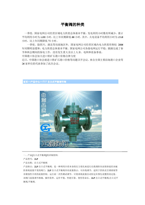
首页>>产品中心>>ZLF自立式平衡调节阀一、产品[自立式平衡阀]的详细资料:产品型号:ZLF产品名称:自立式平衡阀产品特点:ZLF自立式平衡阀,是一种利用介质本身的压力变化来进行自我调控从而保持流经该被控系统流量不变的阀门,ZLF自立式平衡阀具有流量指示,可在线调节,适用于供热及空调系统等非腐蚀性介质的流量控制。
运行前一次性测试调节,可使系统流量自动恒定在预先设置的设定值。
该阀门流量调节准确,操作简单,运作平稳,性能可靠,使用寿命长。
ZLF自立式平衡阀,自立式平衡阀,平衡阀。
二、ZLF自立式平衡阀参数:1.公称压力:1.6MPa2.公称通径:15~350mm3.适用介质:水、油等非腐蚀性液体4.适用温度:0~100℃5.法兰标准:GB/T 17241.6GB/T 91136.试验标准:GB/T 13927API5987.主要零部件材料三、自立式平衡阀材质参考:零件名称材料阀体、阀盖灰铸铁、球铁、铸钢阀杆不锈钢阀瓣铸铜膜片丁腈橡胶四、ZLF自立式平衡调节阀主要外形连接尺寸:D N 152025324565811251520250 300 350 备注L 11111151622152327529313543520 635 670DN15~25为螺纹连接H 1 7272811813813814317193208254289325 357 372H 2 770749114714715418921122726303367 430 495流量0.10.1~1.0.20.51~2~3~5~115~530~840~1100~30150~500200~700m 3/ h ~15 ~2~46 11525~350 0 80 0订货须知:一、①ZLF自立式平衡调节阀产品名称与型号②ZLF自立式平衡调节阀口径③ZLF自立式平衡调节阀是否带附件二、若已经由设计单位选定公司的ZLF自立式平衡调节阀型号,请按ZLF自立式平衡调节阀型号三、当使用的场合非常重要或环境比较复杂时,请您尽量提供设计图纸和详细参数,相关产品:ZZWPE自力式电控温度调节阀ZZYP自力式压力调节阀ZZWP型自力式温度调节阀首页>>产品中心>>KPF型平衡阀一、产品[平衡阀]的详细资料:产品型号:KPF-16型产品名称:平衡阀产品特点:本厂生产的KPF一16型平衡阀是一种具有特殊功能的阀门,具有良好的流量特性,能够合理的分配流量,实现流量定量,可以有效地解决供热(空调)系统中存在的室温冷热不匀问题。
美国飞托克FITOK二通球阀

美国飞托克FITOK二通球阀上海邱炳阀门有限公司描述:316 SS BF Series Ball Valve, 1/4 Female NPT,0.19" Orifice最大工作压力可达:690 bar (10000 psig)工作温度范围:-17°C 至232°C (0°F 至450°F)固定球可双向密封耳轴型球:防止球冲出阀座自动预紧密封二通球阀型号:BFSS-FNS4、BFSS-FL4、BFSS-ML6、BFHSS-FNS2、BFHSS-FL6、BFHSS-ML8球阀。
飞托克FITOK仪表针型阀上海邱炳阀门有限公司描述:316 SS NF Series Needle Valve,6000psig(414bar),1/8 Female NPT, 0.16" Orifice一体式锻造阀体两截式阀杆设计,上阀杆螺纹经特殊硬化处理,下阀杆表面经滚压硬化处理上阀杆螺纹的润滑脂与系统介质隔离非旋转的下阀杆以上下运动代替旋转升降,减少每个行程对填料的摩擦,减少阀座和阀头之间的摩擦可面板安装手柄采用两端螺钉锁紧,稳固耐用多种颜色手柄可供选择每只阀门在出厂前均以额定工作压力的氮气或水进行密封测试最大工作压力NF系列- 不锈钢:414 bar (6000 psig)合金C-276:414 bar 6000 psig)合金 400:345 bar (5000 psig)钛:241 bar (3500 psig)黄铜:207 bar (3000 psig)NFH系列- 不锈钢:689 bar (10000 psig)工作温度PTFE 填料:-54°C 至232°C (-65°F 至450°F)PEEK:-54°C 至260°C (-65°F 至500°F)石墨填料:-54°C 至649°C (-65°F 至1200°F)锻件针型阀;NFSS-FNS2-7、NFSS-FL4-7、NFSS-ML6-7、NFSS-NS6-7、NFSS-FR4-7、NFSS-FO4-7、NFSS-ML10-8、NFSS-TS6-8、NFSS-MTS12-8、NFSS-UMB14-8仪表针型阀飞托克FITOK棒料针型阀上海邱炳阀门有限公司描述:316 SS NB Series Needle Valve,6000psig(414bar),1/8 Female NPT, 0.16" Orifice最大工作压力NB系列—不锈钢:414 bar (6000 psig)合金C-276:414 bar (6000 psig)合金400:345 bar (5000 psig)钛:241 bar (3500 psig)黄铜:207 bar (3000 psig)NBH系列- 不锈钢:689 bar (10000 psig)◎工作温度PTFE 填料:-54°C 至232°C (-65°F 至450°F)PEEK:-54°C 至260°C (-65°F 至500°F)石墨填料: -54°C 至649°C (-65°F 至1200°F)FITOK棒料针型阀:NBSS-FNS2-7、NBSS-NS4-7、NBSS-FL4-7、NBSS-ML6-7、NBSS-FO4-7、NBSS-FR4-7、NBSS-FNS4-8、NBSS-MTS12-8、NBSS-TS6-8、NBSS-UMB14-8、NBSS-MTB14-8针型阀美国飞托克FITOK锻件针型阀上海邱炳阀门有限公司描述:316 SS NF Series Needle Valve,6000psig(414bar),1/8 Female NPT, 0.16" Orifice一体式锻造阀体两截式阀杆设计,上阀杆螺纹经特殊硬化处理,下阀杆表面经滚压硬化处理上阀杆螺纹的润滑脂与系统介质隔离非旋转的下阀杆以上下运动代替旋转升降,减少每个行程对填料的摩擦,减少阀座和阀头之间的摩擦可面板安装手柄采用两端螺钉锁紧,稳固耐用多种颜色手柄可供选择每只阀门在出厂前均以额定工作压力的氮气或水进行密封测试最大工作压力NF系列 - 不锈钢:414 bar (6000 psig)合金C-276:414 bar 6000 psig)合金 400: 345 bar (5000 psig)钛:241 bar (3500 psig)黄铜:207 bar (3000 psig)NFH系列 - 不锈钢:689 bar (10000 psig)工作温度PTFE 填料:-54°C 至 232°C (-65°F 至 450°F)PEEK: -54°C 至 260°C (-65°F 至 500°F)石墨填料:-54°C 至 649°C (-65°F 至 1200°F)锻件针型阀;NFSS-FNS2-7、NFSS-FL4-7、NFSS-ML6-7、NFSS-NS6-7、NFSS-FR4-7、NFSS-FO4-7、NFSS-ML10-8、NFSS-TS6-8、NFSS-MTS12-8、NFSS-UMB14-8针型阀美国飞托克FITOK非旋转阀杆针型阀上海邱炳阀门有限公司描述:316 SS ND Series Needle Valve,3000psig(207bar),12 mm FITOK Tube Fitting,0.25" Orifice一体式锻造阀体直通型和角型结构可选结构紧凑非旋转阀杆手柄具有防污功能每只阀门在出厂前均以最大额定工作压力的氮气进行密封测试最大工作压力:207 bar (3000 psig)工作温度:PCTFE 阀尖:-28 °C 至 93°C (-20°F 至 200°F)PEEK 阀尖:-28 °C 至 232°C (-20°F 至 450°F)FITOK非旋转阀杆针型阀型号:非旋转阀杆针型阀:NDSS-ML12-8、NDSS-NS2-5、NDSS-NS2-FL2-5、NDSS-FL2-5、NDSS-ML3-5、NDSS-FNS2-7针型阀美国飞托克FITOK泄放阀上海邱炳阀门有限公司FITOK泄放阀型号:RBSS-MS14、RBSS-RT8、RBSS-RT6、RBSS-RT4、RBSS-NS8、RBSS-NS6、RBSS-NS4、RBSS-NS2、RBSS-MS20泄放阀描述:316 SS RB Series Bleed Valve, M14x1.5 Male ISO结构紧凑,便于安装阀杆螺纹及阀头镀铬延长阀门的使用寿命最大工作压力:690 ba r (10000 psig)工作温度:-53°C 至 454°C (-65°F 至 850°F)多种端接316 不锈钢,碳钢或合金400材料每个阀门出厂前在 6000 psig 压力下用氮气进行密封性测试飞托克FITOK卡套阴螺纹弯头上海邱炳阀门有限公司描述:FITOK卡套阴螺纹弯头型号:SS-LF-ML6-NS2、SS-LF-ML8-NS2、SS-LF-ML10-NS4、SS-LF-ML12-NS8、SS-LF-ML16-NS6、SS-LF-ML12-NS6、SS-LF-ML10-NS6卡套阴螺纹弯头316 SS Tube Fitting, Female Elbow, 6 mm O.D. × 1/8 Female NPT尺寸范围从 1/16" 至2" 或 2 mm 至 50 mm。
管件中英文对照表

管件中英文对照表 The document was finally revised on 2021●弯头 elbow●异径弯头 reducing elbow●带支座弯头 base elbow●长半径弯头(标准倍弯曲半径)long radius elbow●三通 tee●异径三通 reducing tee●等径三通 straight tee●带侧向口的三通(右向或左向) side outlet tee(right hand or 1eft hand)●异径三通(分支口为异径) reducing tee (reducingon outlet)●异径三通(一个直通口为异径)reducing tee(reducing on one run)●带支座三通 base tee●异径三通(一个直通口及分支口为异径) reducing tee(reducing on one run and outlet)●异径三通(两个直通口为异径,双头式) reducing tee(reducing on both runs, bull head)●45°斜三通 45° lateral●45°斜三通(支管为异径) 45° lateral (reducing onbranch)●45°斜三通(一个直通口为异径) 45° lateral (reducingon one run)●45°斜三通(一个直通口及支管为异径) 45° lateral(reducing on one run and branch)●Y型三通(俗称裤衩)true “Y”●四通 cross●等径四通 straight cross●异径四通 reducing cross●异径四通(一个分支口为异径)reducing cross(reducing on one outlet)●异径四通(一个直通口及分支口为异径) reducingcross (reducing on one run and outlet)●异径四通(两个分支口为异径) reducing cross(reducing on both outlet)●异径四通(一个直通口及两个分支口为异径)reducing cross (reducing on one run and bothoutlet)●异径管 reducer●同心异径管 concentric reducer●偏心异径管 eccentric reducer●锻制异径管 reducing swage●螺纹支管台 threadolet●焊接支管台 weldolet●承插支管台 sockolet●弯头支管台 elbolet●斜接支管台 latrolet●镶入式支管嘴 sweepolet●短管支管台 nipolet●支管台,插入式支管台 boss●Threadolet●elbolet●weldolet;on weld●nipolet●sockolet●weldolet●latrolet●Sockolet●boss●管接头 coupling, full coupling ●半管接头 half coupling●异径管接头 reducing coupling●活接头 union●内外螺纹缩接(俗称补芯) bushing●管帽 cap (C)●堵头 plug●短节 nipple●异径短节 reducing nipple; swage nipple管道英文缩写A Anchor 固定ABS * Absolute 绝对的AISI *American Iron and Steel Institute美国钢铁学会ANSI * American National Standards Institute 美国国家标准学会API *American Petroleum Institute 美国石油学会APPROX *Approximate 大约,近似的ASB Asbestos 石棉ASME *American Society Of Mechanical Engineers 美国机械工程师协会ASSY * Assembly 装配,组装ASTM * American Society Of Testing Material 美国材料实验协会ATM * Atmosphere 大气压AWG * American Wire Gage 美国线规AWS * American Wel**** Society 美国焊接协会AWWA * American Water Works Association 美国水工协会B?BB Bolted Bonnet 栓柱连接的阀盖BB By Buyer 买方供货B-B Beveled End-Beveled End 两端为坡口端BC Bolt Circle 螺栓中心圆Bolted Cover(cap) 螺栓连接的阀兰盖(帽)BE Beveled End (for wel****) 坡口(焊接用)Bell End 承口BEP Both Ends Plain 两端平BET Both Ends Threaded 两端带螺纹BL Battery Limit 装置区边界BF Blind Flange 盲板法兰BLD Blind盲板BLDG *Buil**** 建筑物BM Bill Of Material 材料表BOP Bottom Of Pipe 管底B-P Beveled End —Plain End 坡口端.平端BV Butterfly valve 蝶阀BWG * Birmingham Wire Gage 伯明翰线规BW Butt Weld 对焊CC Cap 管帽C-C Center to Center 中至中C-E Center to End 中至端面C-F Center to Face 中至面CH-OP Chain Operated 链条操纵的Checkered Plate 花纹钢管*Cast Iron 铸铁CL *Class 英制压力等级,等级,种类CLEAR Clearance 间隙COD Continued on Drawing 接续图COL *Column 柱,塔CONC Concentric 同心的CONN Connection 连接,接口CONT *Continue 连续. Control Valve 控制阀CPLG Coupling 管接头,连轴节. Concentric Reducer 同心异径管. *Carbon Steel 碳钢. Cold Spring 冷紧Car Seal Close 在关闭状态下封住 Car Seal Open 在开启状态下封住CUST Customer 客CH Check Valve 止回阀DEG *Degree 度DF Drain funnel 排液漏斗DIA *Diameter 直径DIM *Dimension 尺寸DISCH *Discharge 出口,排出Diaphragm VELVE 隔膜阀DMF Double Male And Female 双重凹凸DN? Norminal Diameter公称直径DN Down 下DR Drain 排液DS Directional Stop 定向限为架DWG * Drawing 图EE *East 东EC External Coating 外面涂防腐层ECC Eccentric 偏心EFW Electric Fusion Welded 电容焊的EL(ELEV) *Elevation 标高;立面ELL Elbow 弯头EQIOP Equipment设备,装置EQUIV Equivalent 相当的. Eccentric Reducer 偏心异经管ERW Electric Resistance Welded 电阻焊的EW Eye Washer & Shower 洗眼器及淋浴器 Expansion Joint 膨胀节FFDN Foundation基础FF Flat Faced Or Full Faced 全平面;满平面F-F Face To Face 面至面FGW Fusion Gas Wel**** 气熔焊FIG *Figure 图FL Floor 楼面FLEX TUBE Flexible Tube 挠性管FLG Flange 法兰FLGD Flanged 法兰式的FLGF Flanged Face 法兰面FOB Flat On Bottom 底面平FOT Flat On Top 顶面平FP Fix Point 固定点FS Forged Steel 锻钢FTF Fitting To Fitting 管件直连FTG Fitting 管件FURND Furnished 提供的,装设的FW Field Weld 现场焊G Guide 导向GA * Gage 表,表压,规(线规)GALV *Galvanize 镀锌GL Ground Level 地面GLV Globe Valve 截止阀GEAR OP Gear Operated 齿轮传动的GMAW Gas Metal Arc Wel**** 金属极惰气体保护焊GSKT Gasket 垫片GTAW (Inert)Gas Tungsten Arc Wel**** 惰性气体保护钨极电弧焊GV Gate Valve 闸阀HH Hanger 吊架HC Hose Connection 软管接头Half Coupling 半节管接头HDR Header 总管HEX *Hexagon 六角形HF Hard Alloy Face on阀内件(阀心)为Valve Trim 硬质合金密封面HH Hand Hole 手孔HOR Horizontal 水平的* High Pressure 高压HS Hose Station 软管IID * Inside Diameter 内径IN * Inch 英寸INS Insulation 隔热INST Instrument仪表INV Invert (inside bottom of pipe) 管子内底IPS Iron Pipe size 铁管尺寸ISO Isometric Drawing 周测图(空视图) Inside Battery Limit 装置边界内恻ISNS Inside screw & Non-rising Stem 内螺纹非升杆ISRS Inside screw & Rising stem 内螺纹升杆JJT Joint 接头JS Jack Screw 顶开(起)螺栓LLC Locked Closed 在关闭状态下锁定LEP Large end plain 大端为平的LET Large end Threaded 大端带螺纹LG Long 长LGF Lens Gasket Face 透镜垫连接面. THD Left Hand Thread 左螺纹LIFT Lift Type 升降式LJ Lap Joint 搭接LJF Lap Joint Flange 松套法兰LO Locked Open 在开启状态下锁定. Low Pressure 低压LR Long Radius 长半径LRE Long Radius Elbow 长半径弯头LTG Large Tongue & Groove 大椎槽MMATL Material 材料MAX Maximum 最大MB Machine Bolt 机器螺栓(单头)MF Male and Female 凸和凹MFG Manufacture 制造MF * Manufacture 制造厂MH Manhole 人孔MI Malleable Iron 可锻铸铁MIN *Minimum 最小MJ Mechanical Joint 机械接头Match Line 连续线MSS * Manufacturers Standardization Society of the Valve and Fittings Industry, Inc.美国阀门和管件制造商标准化协会MTO Material take-off 材料统计MW Minimum Wall 最小壁厚. Mineral Wool 矿(物)棉NN * North 北NB Nominal Bore 公称孔径. Non-Bonnet 无阀盖NC Normally Closed 常闭NIP Nipple 短管NO Normally Open; 常开*Number号;数量NO INS No Insulation 不隔热NOM Nominal 公称的;额定的NOZ Nozzle 管口NPS Nominal Pipe Size 公称管径NPSH Net Positive Suction Head 净正吸入压头NPT *American National Taper 美国锥管螺纹Pipe ThreadNS Nominal Size 公称直径NV Needle Valve 针形阀OOD *Outside Diameter 外径OET One end Threaded 一端带螺纹OR Outside Radius 外半径ORF Orifice 孔板ORIENT Orientation 方位OS & Y Outside Screw and Yoke 外螺纹阀杆和阀轭OSNB Outside Screw Non-Bonnet 外螺纹无阀盖PP Plug 堵头PAP Piping Arrangement Plan管道布置平面图PB Pressure Seal Bonnet 压力密封的阀盖P-B Plain End –Bevel End 平端—坡口端PC Pressure Seal Cap 压力密封的阀帽Pitch Circle Diameter 节圆直径PE Plain End (not beveled) 平端(无坡口)PF Platform 平台PID Piping & Instrument Diagram管道及仪表流程图PN *Nominal Pressure 公称压力PN Plant North 工厂北向POS point of Support 支承点P-P Plain End—Plain End 两端为平端PREP Preparation 加工准备PSIA *Pounds Per Square Inch Absolute 磅/PSIG Pounds Per Square Inch Gage 磅/PT Point 点PTFE *Polytetrafluoroethylene 聚四氟乙烯 Part No. 件号PV Plug Valve 旋塞阀PVC *Poly Vinyl Chloride 聚氯乙烯QQTY *Quantity 数量RR * Radius 半径RED Reducer 异径管REF Reference 参考REINF Reinforce 加强REQD Required 需要;申请REV *Revision 修改RF Raised Face 凸面RG Ring Gasket 环形垫片Right Hand Thread 右螺旋RJ Ring Joint 环垫接头RO Restriction Orifice 限流孔板RPM * Revolutions Per Minute 转/分RPS * Revolutions Per Second 转/秒RS Resting Support 支承架,滑动架RTJ Ring Type Joint(见RJ)RV Relief Valve 安全泄液阀SS *South 南S Spring 弹簧(管架用)SAW (Automatic)Submerged Arc Wel**** 自动埋弧焊SB Stud Bolt 双头螺栓SB Screwed Bonnet 螺纹阀盖SC Sample Cooler 取样冷却器SCH * Schedule 管壁厚系列号SCRD Screwed 螺纹SEP Small end Plain 小端为平的SET Small end Threaded 小端带螺纹SF Semi-Finished 半光SG Sight Glass 视镜SH Surface Hard Facing 硬质密封面SK Sketch 草图SMAW Shielded Metal Arc Wel**** 有保护的金属电弧焊SMLS Seamless 无缝SN Swaged Nipple 异径短管SO Slip – On 滑套SOF Slip – On Flange 滑套法兰SPEC * Specification 规定,说明SPL Sound Pressure Lever 升压水准SQ * Square 方的,平方SR Shout Radius 短半径SRE Short Radius Elbow 短半径弯头SS *Stainless Steel 不锈钢ST Steam Trap蒸汽疏水阀STD *Standard 标准STG Small Tongue & Groove 小椎槽面STL *Steel 钢STM Steam 蒸汽Steam Tracing 蒸汽拌热SUCT Suction 吸入口SV Safety Valve 安全泄气阀SW Socket Weld 承插焊SWG Swage 锻造,模锻SWMG Swing Type 旋启式SYM Symmetrical 对称的TT Tee 三通TE Threaded End 螺纹端TEMP *Temperature温度TG Tongue & Groove 椎槽THD *Threaded 螺纹的THK *Thickness 厚度TL Tangent Line 切线TN True North 真实北向TOC Top of Concrete 混凝土北向TOP Top of pipe 管顶TOS Top of Support 支架顶面Top Top of Steel 钢结构顶面TY P Typical 典型的UUB Union Bonnet 带活接头的阀盖UC Union Cap 带活接头的阀帽UN Union 活接头VV Valve 阀VAC Vacuum 真空VAR Variable 可变的VERT Vertical 垂直的VOL *Volume 卷,册,容量,体积WW * West 西WB Weld Branch 焊接支管WC Weld Cap 焊接管帽WD Width 宽度WE Weld End 焊接端WL Wel**** Line 焊接线WN Wel**** Neck 对焊法兰(颈部)WNF Weld Neck Flange 对焊法兰WP Working Pressure 工作压力. Working Point 工作点WT Wall Thickness 壁厚Weight 重量XXH Extra Heavy 加强的,加厚的XXH Double Extra Heavy 双倍加强(厚)的XS Extra Strong 加强的XXS Double Extra Strong 双倍加强的YYP Yield Point 屈服点Fittingelbow异径弯头 reducing elbow带支座弯头 base elbowk半径弯头 long radius elbow短半径弯头 short radius elbow长半径180°弯头 long radius return短半径180°弯头 short radius return带侧向口的弯头(右向或左向) side outlet elbow (right hand or left hand)双支管弯头(形) double branch elbowtee异径三通 reducing tee等径三通 straight tee带侧向口的三通(右向或左向) side outlet tee (right hand or 1eft hand)异径三通(分支口为异径) reducing tee (reducing on outlet)异径三通(一个直通口为异径) reducing tee (reducing on one run)带支座三通 base tee异径三通(一个直通口及分支口为异径) reducing tee (reducing on one run and outlet)异径三通(两个直通口为异径,双头式) reducing tee (reducing on both runs, bull head)45°斜三通 45° lateral45°斜三通(支管为异径) 45° lateral (reducing on branch)45°斜三通(一个直通口为异径) 45° lateral (reducing on one run)45°斜三通(一个直通口及支管为异径) 45° lateral (reducing on one run and branch)Y型三通(俗称裤衩)true “Y”四通 cross等径四通 straight cross异径四通 reducing cross异径四通(一个分支口为异径 reducing cross (reducing on one outlet)异径四通(一个直通口及分支口为异径) reducing cross (reducing on one run and outlet)异径四通(两个分支口为异径) reducing cross (reducing on both outlet)异径四通(一个直通口及两个分支口为异径)reducing cross (reducing on one run and both outlet)异径管 reducer同心异径管 concentric reducer偏心异径管 eccentric reducer锻制异径管 reducing swage螺纹支管台 threadolet焊接支管台 weldolet承插支管台 sockolet弯头支管台 elbolet斜接支管台 latrolet镶入式支管嘴 sweepolet短管支管台 nipolet支管台,插入式支管台 boss管接头 coupling, full coupling半管接头 half coupling异径管接头 reducing coupling活接头 union内外螺纹缩接(俗称补芯) bushing管帽 cap (C)堵头 plug短节 nipple异径短节 reducing nipple; swage nipple 弯管 Bend预制弯管 fabricated pipe bend跨越弯管(^ 形) cross-over bend偏置弯管(~ 形) offset bend90°弯管 quarter bend环形弯管 cirele bend单侧偏置90°弯管(形) single offset quarter bendS形弯管“S” bend单侧偏置U形膨胀弯管(|形)single offset “U” bendU形弯管“U” bend双偏置U膨胀弯管double offset expansion “U” bend斜接弯管 mitre bend三节斜接弯管 3-piece mitre bend折皱弯管 corrugated bend圆度 roundnessFlange (FLG)整体管法兰 integral pipe flange法兰 steel pipe flange螺纹法兰 threaded flange滑套法兰(包括平焊法兰) slip-on flange (SO); slip-on welding flange承插焊法兰 socket welding flange松套法兰 lap joint flange (LJF)对焊法兰 welding neck flange (WNF)法兰盖 blind flange, blind孔板法兰 orifice flange异径法兰 reducing flange盘座式法兰pad type flange松套带颈法兰 loose hubbed flange焊接板式法兰welding plate flange对焊环 welding neck collar (与stub end相似)平焊环 welding-on collar突缘短节 stub end, lap翻边端 lapped pipe end松套板式法兰 loose plate flange压力级 pressure rating, pressure rating class压力—温度等级 pressure-temperature rating 法兰密封面,法兰面 flange facing突面 raised face (RF)凸面 male face (MF)凹面 female face (FMF)榫面 tongue face槽面 groove face环连接面 ring joint face全平面;满平面 flat face; full face (FF) 光滑突面 smooth raised face (SRF)法兰面加工 facing finish粗糙度 roughness光滑的 smooth齿形 serrated均方根 root mean square (RMS)算术平均粗糙高度 arithmetical average roughness height (AARH)配对法兰 companion-flange螺栓圆 bolt circle .)垫片 Gasket (GSKT)垫片的型式 type of gasket平垫片 flat gasket环形平垫片 flat ring gasket平金属垫片 flat metal gasket夹棉织物的橡胶 elastomer with cotton fabric insertion夹石棉织物的橡胶 elastomer with asbestos fabric insertion夹石棉织物及金属丝加强的橡胶 elastomer with asbestos fabric insertion and with wire reinforcement无石墨压缩白石棉垫片 non graphited compressed white asbestos gasket天然白橡胶垫片 natural white rubber gasket 压缩石棉垫片 compressed asbestos class gasket浸聚四氟乙烯的石棉垫片 PTFE impregnated asbestos gasket夹石棉的缠绕金属垫片 spiral-wound metal gasket with asbestos filler内环 inner ring外环,外定位环 outer ring波纹金属垫片 corrugated metal gasket波纹金属包嵌石棉垫片 corrugated metal gasket with asbestos inserted双夹套波纹金属包石棉垫片 corrugated metal double jacketed asbestos filled gasket双夹套垫片 double jacketed gasket金属包石棉平垫片 flat metal jacketed asbestos filled gasket整体金属齿形垫片 solid metal serrated gasket 槽形金属垫片 grooved metal gasket环形连接金属垫片 ring joint metal gasket 八角环形垫片 octagonal ring gasket椭圆环形垫片 oval ring gasket透镜式垫片 lens gasket非金属垫片 non-metallic gasketTOE是Threaded One End的缩写,意思是一端螺纹POE是Plain One End的缩写,意思是一端平口TBE是Threaded Both End的缩写,意思是两端螺纹PBE是Plain Both End的缩写,意思是两端平口TOE&POE就是一端平口,另一端螺纹连接TBE是两头都是螺纹连接PBE是两头都是平口(焊接)BBE 两端都是坡口。
二位三通电磁阀
二位三通电磁阀目录二位三通双动自保持球阀二位三通球阀-KHB3K、BK3二位三通球阀液压阀门>>液压球阀>>二位三通球阀产品名称:二位三通球阀产品型号:KHB3K 、BK3产品口径:DN4-50产品压力:1.0-50.0Mpa 产品材质:铸钢、不锈钢等产品概括:生产标准:国家标准GB 、机械标准JB 、化工标准HG 、美标API 、ANSI 、德标DIN 、日本JIS 、JPI 、英标BS 生产。
阀体材质:铜、铸铁、铸钢、碳钢、WCB 、WC6、WC9、20#、25#、锻钢、A105、F11、F22、不锈钢、304、304L 、316、316L 、铬钼钢、低温钢、钛合金钢等。
工作压力1.0Mpa-50.0Mpa 。
工作温度:-196℃-650℃。
连接方式:内螺纹、外螺纹、法兰、焊接、对焊、承插焊、卡套、卡箍。
驱动方式:手动、气动、液动、电动。
产品详细信息KHB3K(BK3)系列二位三通球阀图形符号型号说明①系列代号:KHB3K(BK3)系列二位三通球阀②连接代号:M**、G**、**LR、**SR、PT**、NPT**③阀体材料:1-钢、2-不锈钢④球体材料:1-钢、2-黄铜、3-不锈钢⑤工作温度:1、-25~+100℃2、-30~+170℃⑥其他密封:2-丁晴橡胶、4-氟橡胶⑦手柄形式:01-铝质直柄02-铝质曲柄03-铸锌直柄04-铸锌曲柄05-钢质直柄06-钢质曲柄09-不带手柄⑧设计序号:由生产商定⑨表面处理:空白-磷化、G-电镀黄锌外形尺寸尺寸表连接口略图:简略型号PN(bar)DN LW RA d1i L L1B H h1h2h3SW1SW2S KHB3K-M16×1.5500060611M16×1.5116940264513.5338092227.5 KHB3K-M22×1.5500080816M22×1.51276423249163610092733 KHB3K-M27×1.5500101020M27×1.51276423249163610092733 KHB3K-M30×1.5400161524M30×1.51384483861194511093237 KHB3K-M36×2315202030M36×215103604870255511124145.5 KHB3K-M42×2315252335M42×21811665577928.56411125054 KHB3K-M52×2315323240M52×220149847510137.58412146070 KHB3K-M60×2315403845M60×222174918511242.59512147084简略型号PN(bar)DN LW RA d1i L L1B H h1h2h3SW1SW2S KHB3K-G1/85000406/G1/8106940264513.5338092235 KHB3K-G1/45000606/G1/4146940264513.5338092235 KHB3K-G3/85001010/G3/81472423249163610092736 KHB3K-G1/25001312/G1/21683483549174010093040 KHB3K-G1/24001615/G1/21683483861194511093242KHB3K-G3/43152020/G3/41895604870255511124149 KHB3K-G1*******/G12111365577928.56411125056.5 KHB3K-G11/43153232/G11/422110847510137.58412146062.5 KHB3K-G11/23154038/G11/224130918511242.59512147061 KHB3K-G2*******/G22614010010513152.511212148062.5简略型号PN(bar)DN LW RA d1i L L1B H h1h2h3SW1SW2S KHB3K-NPT1/85000406/NPT1/8106940264513.5338092235 KHB3K-NPT1/45000606/NPT1/4146940264513.5338092235 KHB3K-NPT3/85001010/NPT3/81472423249163610092736 KHB3K-NPT1/25001312/NPT1/21683483549174010093040 KHB3K-NPT1/24001615/NPT1/21683483861194511093242 KHB3K-NPT3/43152020/NPT3/41895604870255511124149 KHB3K-NPT13152525/NPT12111365577928.56411125056.5 KHB3K-NPT11/43153232/NPT11/422110847510137.58412146062.5 KHB3K-NPT11/23154038/NPT11/224130918511242.59512147061 KHB3K-NPT23155048/NPT22614010010513152.511212148062.5简略型号PN(bar)DN LW RA d1i L L1B H h1h2h3SW1SW2S KHB3K-06LR500040406M12×1.5106740264513.5338092233.5 KHB3K-08LR500060608M14×1.5106740264513.5338092233.5 KHB3K-10LR500080810M16×1.51174423249163610092737 KHB3K-12LR500101012M18×1.51174423249163610092737 KHB3K-15LR500131215M22×1.51282483553174010093040 KHB3K-15LR500121215M22×1.51282483861194511093240 KHB3K-18LR500131218M26×1.51282483553174010093042 KHB3K-18LR400161518M26×1.51282483861194511093242 KHB3K-22LR315201922M30×214101604870255511124152 KHB3K-28LR315252428M36×21410865577928.56411125054 KHB3K-35LR315323035M45×216141847510137.58412146066 KHB3K-42LR315403642M52×216162918511242.59512147078简略型号PN(bar)DN LW RA d1i L L1B H h1h2h3SW1SW2S KHB3K-08SR500040508M16×1.5127340264513.5338092237 KHB3K-10SR500060610M18×1.5127340264513.5338092237 KHB3K-12SR500080812M20×1.51276423249163610092738 KHB3K-14SR500101014M22×1.51480423249163610092740 KHB3K-16SR500131216M24×1.51486483553174010093044 KHB3K-16SR50012</DIV二位三通双动自保持球阀一、产品概述:ZBF23QS-6~150型双动自保持球阀主要是由阀体和驱动机构组成,是一种二位三通自保持阀门,既可手动,又可电动。
美国博雷(BRAY)VCB F系列 2通3通法兰式球阀
C B
B
D
1/2 A
A
C
2 通尺寸
A
3 通尺寸(侧视图)
A
3 通尺寸(俯视图)
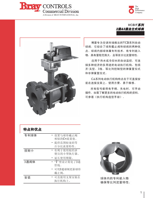
3通带球体嵌入物的阀门
连 in. 4 5 6 接 mm 100 125 150 孔数 8 孔直径 Φ19 A in. 12 14 16 mm 305 356 406 in. 9 10 11 B mm 229 254 279 in. 14 15 16 C mm 356 381 406 D* in. 18-1/2 20 20-1/2 mm 470 508 521 重 lb 75 90 105 量 kg 34 41 48
2
CONTROLS
R
Commercial Division
A Division of BRAY INTERNATIONAL, Inc.
The High Performance Company
2通带球体嵌入物球阀选型表
连 in. 2-1/2 接 mm 63 型号 # 1 VCB2723A_ VCB2724A_ VCB2725A_ VCB2826A_ VCB2827A_ VCB2828A_ VCB4091F2 VCB4152F2 VCB4254F2 VCB5185F2 VCB5240F2 VCB5400F2 VCB6348F2 VCB6441F2 VCB6650F2 流量系数 Cv 55 72 202 82 124 145 91 152 254 185 240 400 348 441 650 Kv 47 62 174 71 107 125 78 131 218 159 206 344 299 379 559 闭合时 P 2 值 PSI kPa
阀体压力 连接端口 温度范围 材 质 阀 体 球 体 阀 杆 球体嵌入物 阀杆密封 (2) 阀 座
Series BV3HL三件部分卫生漏流球阀指导书说明书

SPECIFICATIONSService:Compatible liquids and gases.Body:3-piece.Line Size:1/2˝ to 4˝.End Connections:Tri-Clamp (liner meets BS 4825, part 3).Pressure Limits:1000 psi (69 bar) WOG. Wetted Materials:Body, Ball, End Caps: CF8M stainless steel.Stem: 316 stainless steel. Stem Seal: Fluoroelastomer.Seats, Body Seal, Thrust Washer, Packing: PTFE.Temperature Limits:-40 to 450°F (-40 to 232°C) CWP . 297°F (147°C) steam maximum.Other Materials:304 stainless steel, vinyl.INSTALLATIONGeneral Information for On-Site Installation - The valve may be fitted in any position in the pipeline. For automated operation, W.E.Anderson does recommend that the valve and actuator be installed vertically in case of valve leakage, although this is not necessary for proper operation of the valve. To prevent damage to the seats and ball surface, the pipeline must be flushed so that it is free of dirt, burrs and welding residues before installing the valve.Installation of Clamp End Valves -Use the proper clamp and O-ring for pressure range of application. Place the O-ring into the O-ring groove on the clamp end. Slide the valve between the clamp fittings while making sure that the O-ring remains in place. Install the clamp over both valve ends and clamp fitting to insure alignment. Tighten both clamps on each valve end. Check proper operation of valve (manually or with the actuator).The Series BV3HL Three-Piece Sanitary Ball Valve provideseasy replacement of gaskets, seals, and seats without any special tools. The swing-out design of the valve allows for the center section of the valve body to be replaced while leaving the ends clamped in place if necessary.The BV3HL uses a cavity filled design, which means that the ball can remain completely enclosed by the pure TFE seats, eliminating the chance of product entrapment. Combined with an investment cast 316L stainless steel casting, this series of valve is ideal for food, beverage, semi-conductor, or pharmaceutical applications.Superior leak protection is accomplished by using a live-loaded packing system featuring belleville washers. An ISO 5211mounting pad is provided for easy automation.OPERATIONManual Operation - To open or close the valve, turn the handle 90° (1/4 turn). Valve in OPEN position: the handle is parallel (in line)with the valve or pipeline. Valve in CLOSED position: the handle is perpendicular (crossed) with the valve or pipeline.Automated Operation -Valves with actuators should be checked for stem alignment. Most applications are direct mount to the actuator, greatly reducing any sideload or increased torque.Make sure that all insert adapters are properly placed on the valve stem and fully engaged in the actuator.©Copyright 2010 Dwyer Instruments, Inc.Printed in U.S.A. 2/10FR# R2-443348-00 Rev. 1Disassembling and Cleaning the Valve -CAUTION: Ball valves can trap fluids in the ball cavity when it is in the closed position. If the valve has been used with hazardous media, it must be decontaminated before disassembly or handling.WARNING:All persons involved in the removal or disassembly of the valve should wear protective gear such as eye and face protection, gloves, etc.Relieve the line pressure. Place the valve in the half-open position and flush the line to remove any hazardous material(s) from the valve.Replacing the Thrust Washer, Packing, and Seats -A repair kit is available for all valves comprising: seats, body seal, stem seal, thrust washer, and stem packing.NOTE:The Series BV3HL Sanitary Ball Valve is designed with belleville washers for automatic wear compensation. If there are signs of leakage from the stem, it is time to replace the stem packing and thrust washer.Before replacing the thrust washer, seats, and packing, the pipeline must be depressurized. Maintenance, removal and replacement of seats and seals is simple even if the valve is installed in line. By removing three of the body bolts and loosening the fourth bolt, the valve body can be swung out of line (see illustration 1.1). Seats, seals, gaskets and balls can be replaced without disturbing the pipe alignment.Bolt Tightening Specifications -The body bolts on the valve must be tightened evenly. Tighten the bolts by hand, then use a wrench to tighten bolts in diagonal opposition. See chart 1.2 for bolt torque specifications.WARRANTYThe Series BV3HL Sanitary Ball Valve is warranted from defects in materials and workmanship for (1) year from the date of purchase.In the unlikely event the valve should fail, the unit can be returned to the factory for warranty repair if the warranty period has not expired. Contact our customer service department for an RGA number and to set up the return.CHART 1.2: Bolt TorquesValve Size1/4˝3/8˝1/2˝3/4˝1˝1-1/2˝2˝2-1/2˝3˝Body Bolt Torque (IN LBS)4444536289186230336487ILLUSTRATION 1.1: Swing-out Design。
Belimo F6250L 250mm 螺纹钢阀门 液体冷热水使用说明书
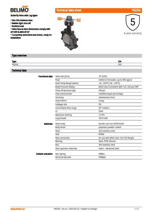
F6250LButterfly Valve with Lug types• Disc 304 stainless steel • Bubble tight shut-off • Resilient seat• Valve face-to-face dimensions comply with API 609 & MSS-SP-67• Completely assembled and tested, ready for installationType overviewType DN F6250L250Technical dataFunctional dataValve size [mm]10" [250]Fluidchilled or hot water, up to 60% glycol Fluid Temp Range (water)-22...250°F [-30...120°C]Body Pressure Rating ANSI Class Consistent with 125, 232 psi CWP Close-off pressure ∆ps 200 psiFlow characteristic modified equal percentage Servicing maintenance-free Flow Pattern 2-way Leakage rate0%Controllable flow range 90° rotation Cv5340 Maximum Velocity 12 FPS Lug threads7/8-9 UNCMaterialsValve body Ductile cast iron ASTM A536Body finish polyester powder coated Stem 420 stainless steel SeatEPDMPipe connection for use with ANSI class 125/150 flanges Bearing Steel, PTFE, Bronze Disc304 stainless steel Gear operator materialsGears - hardened steel Suitable actuatorsNon-Spring PRB(X)Electrical fail-safePKRB(X)F6250L Product featuresFlow/Mounting detailsDimensionsType DN WeightF6250L25061 lb [28 kg]Valve with PRB(X) ActuatorA B C D E F Number of Bolt Holes12.0" [304] 2.8" [70]26.4" [671]18.6" [473]7.8" [199]7.8" [199]12F6250LValve with PKR ActuatorA B C D E F Number of Bolt Holes12.0" [304] 2.8" [70]28.7" [730]20.9" [530]7.8" [199]7.8" [199]12On/Off, Floating point, Non fail-safe, 24...240 VTechnical dataElectrical data Nominal voltage AC 24...240 V / DC 24...125 VNominal voltage frequency50/60 HzRemark about nominal voltage range AC 19.2...264 V / DC 19.2...137.5 VPower consumption in operation20 WPower consumption in rest position7 WTransformer sizing with 24 V 20 VA / with 240 V 52 VAAuxiliary switch2x SPDT, 1 mA...3 A (0.5 A inductive), DC 5 V...AC250 V (II, reinforced insulation), 1x 10° / 1x0...90° (default setting 85°)Switching capacity auxiliary switch 1 mA...3 A (0.5 A inductive), DC 5 V...AC 250 V(II, reinforced insulation)Electrical Connection Terminal blocks, (PE) Ground-ScrewOverload Protection electronic thoughout 0...90° rotationFunctional data Direction of motion motor reversible with appManual override7 mm hex crank, suppliedAngle of rotation90°Running Time (Motor)35 s / 90°Noise level, motor68 dB(A)Position indication integral pointerSafety data Power source UL Class 2 SupplyDegree of protection IEC/EN IP66/67Degree of protection NEMA/UL NEMA 4XEnclosure UL Enclosure Type 4XAgency Listing cULus acc. to UL60730-1A/-2-14, CAN/CSAE60730-1:02, CE acc. to 2014/30/EU and2014/35/EUQuality Standard ISO 9001Ambient humidity Max. 100% RHAmbient temperature-22...122°F [-30...50°C]Storage temperature-40...176°F [-40...80°C]Servicing maintenance-freeWeight Weight13 lb [6.1 kg]Materials Housing material Die cast aluminium and plastic casingApplicationOperationProduct featuresPR Series valve actuators are designed with an integrated linkage and visual position indicators. For outdoor applications, the installed valve must be mounted with the actuator at or above horizontal. For indoor applications the actuator can be in any location including directly under the valve.The PR series actuator provides 90° of rotation and a visual indicator shows the position of the valve. The PR Series actuator uses a low power consumption brushless DC motor and is electronically protected against overload. A universal power supply is furnished to connect supply voltage in the range of AC 24...240 V and DC 24...125 V. Included is a smart heater with thermostat to eliminate condensation. Two auxiliary switches are provided; one set at 10° open and the other is field adjustable. Running time is field adjustable from 30...120 seconds by using the Near Field Communication (NFC) app and a smart phone.†Use 60°C/75°C copper wire size range 12...28 AWG, stranded or solid. Use flexible metal conduit. Push the listed conduit fitting device over the actuator’s cable to butt against the enclosure. Screw in conduit connector. Jacket the actuators input wiring with listed flexible conduit. Properly terminate the conduit in a suitable junction box. Rated impulse Voltage 4000 V. Type of action 1. Control pollution degree 3.AccessoriesMechanical accessoriesDescriptionType Hand crank for PR, PKR, PMZG-HND PRElectrical installationMeets cULus requirements without the need of an electrical ground connection.Universal Power Supply (UP) models can be supplied with 24 VAC up to 240 VAC, or 24 VDC upto 125 VDC.Disconnect power.Provide overload protection and disconnect as required.Two built-in auxiliary switches (2x SPDT), for end position indication, interlock control, fanstartup, etc.Actuators may be controlled in parallel. Current draw and input impedance must be observed.Warning! Live electrical components!During installation, testing, servicing and troubleshooting of this product, it may be necessary to work with live electrical components. Have a qualified licensed electrician or other individual who has been properly trained in handling live electrical components perform these tasks. Failure to follow all electrical safety precautions when exposed to live electrical components could result in death or serious injury.Wiring diagramsOn/OffWiring diagrams On/OffFloating PointAuxiliary SwitchesElectrical installation。
- 1、下载文档前请自行甄别文档内容的完整性,平台不提供额外的编辑、内容补充、找答案等附加服务。
- 2、"仅部分预览"的文档,不可在线预览部分如存在完整性等问题,可反馈申请退款(可完整预览的文档不适用该条件!)。
- 3、如文档侵犯您的权益,请联系客服反馈,我们会尽快为您处理(人工客服工作时间:9:00-18:30)。
5
125
70
482
6
150
3
表中为主管路的流量系数.旁通流量系数为主管路的 80%.
3
CONTROLS
R
Commercial Division
A Division of BRAY INTERNATIONAL, Inc.
The High Performance Company
2通带球体嵌入物的阀门
连 in. 2-1/2 3 4 5 6 接 mm 65 80 100 125 150 孔数 4 Φ19 8 孔直径 A in. 7 9 11 12-3/8 13-7/8 mm 178 227 279 315 353 in. 7 7-3/8 9 10 11 B mm 178 188 229 254 279 C* in. 12 12-3/8 18-13/16 19 19-7/8 重 mm 305 315 478 483 505 lb 22 26 65 75 90 量 kg 10 12 29 34 41
4
�
100
689
3
75
4
100
5
125
70
482
6
1
150
2-1/2 和 3" 阀门,尾号 "1" 代表黄铜, "2" 代表不锈钢. 关断压差 P 是基于以下最小扭矩: 2-1/2 和 3"阀门: 45 lb.-in. 4"阀门: 88lb.-in. 5"和 6"阀门: 140lb.-in.
2
3通带球体嵌入物球阀选型表
连 in. 4 接 mm 100 型号 # VCB34091F2 VCB34152F2 VCB34254F2 VCB35185F2 VCB35240F2 VCB35400F2 VCB36348F2 VCB36441F2 VCB36650F2 流量系数 3 Cv 91 152 254 185 240 400 348 441 650 Kv 78 131 218 159 206 344 299 379 559 闭合时P 2 值 PSI kPa
C B
B
D
1/2 A
A
C
2 通尺寸
A
3 通尺寸(侧视图)
A
3 通尺寸(俯视图)
3通带球体嵌入物的阀门
连 in. 4 5 6 接 mm 100 125 150 孔数 8 孔直径 Φ19 A in. 12 14 16 mm 305 356 406 in. 9 10 11 B mm 229 254 279 in. 14 15 16 C mm 356 381 406 D* in. 18-1/2 20 20-1/2 mm 470 508 521 重 lb 75 90 105 量 kg 34 41 48
CONTROLS
R
Commercial Division
A Division of BRAY INTERNATIONAL, Inc.
The High Performance Company
VCB/F 系列 2 通 &3 通法兰式球阀
博雷专为空调市场推出的VCB系列自动 球阀,它综合了球形截止阀和球阀的两种优 点.球阀内部球体属专利技术,有专利嵌入 物,具有量程范围大,及等百分比流量特性. 应用于热水或冷却水的自动温控,可连 接多种经济的多用途的电动执行机构,包括 开/关型.3线.等比列控制型的弹簧复位式 和非弹簧复位式. CA系列电动执行机构特点在于可直接安 装在连接支架上,使用方便,易于维修. 所有型号都带有手柄,失电时,可手动 操作.如需了解更多的电动执行机构的资料, 可参看《执行机构选型手册》.
2
CONTROLS
R
Commercial Division
A Division of BRAY INTERNATIONAL, Inc.
The High Performance Company
2通带球体嵌入物球阀选型表
连 in. 2-1/2 接 mm 63 型号 # 1 VCB2723A_ VCB2724A_ VCB2725A_ VCB2826A_ VCB2827A_ VCB2828A_ VCB4091F2 VCB4152F2 VCB4254F2 VCB5185F2 VCB5240F2 VCB5400F2 VCB6348F2 VCB6441F2 VCB6650F2 流量系数 Cv 55 72 202 82 124 145 91 152 254 185 240 400 348 441 650 Kv 47 62 174 71 107 125 78 131 218 159 206 344 299 379 559 闭合时 P 2 值 PSI kPa
CONTROLS
R
Commercial Division
A Division of BRAY INTERNATIONAL, Inc.
The High Performance Company
管线图(阀门流动方式):
2通 3 通 混和 3通换向
AB
A
返回
返回
B
盘管
盘管
AB A
阀门标志为A,B,AB,所 有3通阀门出厂时,设 定为逆时针方向指向 0°C,如 需 不 同 的 流 动 方向,请咨询当地的 博雷分公司.
补给
补给
B
3通混和: 介质从两个输入端 口 A, B进 入 , 从 一 个输出端口AB流出.
3通换向: 介质从一个输入端 口 AB进 入 , 从 两 个 输出端口A和B流出.
特 点
应 用 流程特性 阀座泄漏 行 程 闭合压力 热水和冷却水, 50%甘醇 等百分比例 符合 ANSI Class IV 标准 (<0.01% Cv值) 90° 参阅B- 3页图表 2-1/2 和 3 阀门 360 psi (25 bar) ANSI Class 125 法兰连接 -20°F to 240°F (-29°C to 116°C) 4-6阀门 240 psi (16 bar) ANSI Class 125 法兰连接 20°F to 250°F (-7°C to 121°C)
特点和优点
专利球体
设置与球形截止阀 相似的Cv流量值. 提供范围较宽的等 百分比流量特性. 有利于使用较经济 便宜的小型执行器. 延长使用期限. "T"型设计简化了3通 管线. 可用3通球阀更新球形 截止阀. 可直接用支架安装在 执行机构上.
扭矩小
3通阀体
安装
球体内的专利嵌入物 确保等比列流量特性. 1
*尺寸会根据执行机构变化.表中尺寸为 阀门配最大非弹OLS
R
Commercial Division
A Division of BRAY INTERNATIONAL, Inc. 13333 Westland East Blvd. Houston, Texas 77041 Toll Free: 888.412.BRAY(2729), FAX 281.894.9499 2003 Bray International. All rights reserved. VCBF091406 Bray is a registered trademark of Bray International, Inc.
阀体压力 连接端口 温度范围 材 质 阀 体 球 体 阀 杆 球体嵌入物 阀杆密封 (2) 阀 座
2-1/2 和 3 阀门 锻造黄铜 镀镍铜 (可提供不锈钢) 黄铜 (可提供不锈钢) 玻璃纤维填充聚合物 乙丙橡胶 O型圈 增强聚四氟乙烯
4-6 阀门 铸铁 不锈钢 不锈钢 非插入式激光切割不锈钢 乙丙橡胶 O型圈 增强聚四氟乙烯