电源供应器设备机操作说明书A0
电力供应器加热设备手册说明书
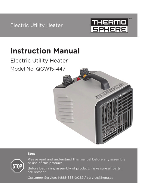
Instruction Manual Electric Utility Heater Model No. QGW15-447Table of ContentsSpecificationsImportant Safety Instructions Operating Instructions Important Safety Features Care and Maintenance Warranty 2 3 5 6 6 6SpecificationsModel Number : QGW15-447Voltage Rating : 120 V AC (60 Hz)BTU Output : 5,120 BTUsAmps : 12.5 AUnit Size : 5” (W) x 6.3” (D) x 5” (H) Unit Weight : 2.66 lbs.Important Safety InstructionsImportant InstructionsWhen using electrical appliances, basic precautions should always be followed to reduce the risk of fire, electric shock and injury to persons, including the following:1. Read all the instructions before using this heater/fan.2.This heater/fan is hot when in use. T o avoid burns, do not let bare skin touch hot surfaces. Use provided handle when moving this heater. Keep combustible materials, such as furniture, pillows, bedding, papers, clothes and curtains at least 3 feet (0.9 meters) from the front of the heater-fan and keep them away from the sides and rear.3. Do not leave heater operating while unattended. Use of extreme caution is necessary when any heater is used by or near children, invalids, disabled persons or pets.4.Do not operate the heater with a damaged power cord or after the heater malfunctions, has been dropped or damaged in any manner. Return heater to authorized service facility for examination, electrical or mechanical adjustment or repair.5. Do not use heater outdoors.6.Use your heater only in dry environments. This heater is not intended for use in a bath room, laundry area, or similar locations, or near sinks, washing machines, swimming pools or other sources of water. Never locate heater where it may fall into a bathtub or other water container. Do not use in damp environments such as flooded basements.7. Do not place the heater on a small, unlevel, uneven or any surface which might allow heater to tip or fall.8.For proper operation, heater should be placed on a smooth, non-combustible surface. Do not place on rugs, carpet, vinyl flooring or other plastic surfaces. Not for use outdoors or in wet areas.9. This heater is not designed as a primary heat source.10. Always plug heaters directly into a wall outlet/ receptacle. Never use with an extension cord orrelocatable power tap (outlet/power strip). Always unplug heater when not in use.11. Do not run power cord under carpeting. Do not cover cord with throw rugs, runners or similar coverings.13. Do not insert or allow foreign objects to enter any ventilation or exhaust opening as this may cause anelectric shock or fire or damage the heater.Intended use:applications. Use only with electrical wiring that is in good working order and that meets applicable codes and ordinances. This heater must be plugged in to a 120V AC, 15 Amp. (or larger) circuit. Do not plug any other appliance into the same circuit. If you have any questions whether your wiring is adequate, consult a qualified electrician. Risk of fire, overheating, malfunction, property damage, injury or even death may result if not adhered to.Use your heater-fan only with a working smoke detector located in the vicinity of this appliance.While using your heater/fan, you should follow the IMPORTANT INSTRUCTIONS listed below. As part of those instructions, we have used the word WARNING to indicate the level of hazard: WARNING indicates a hazard which, if not avoided, could result in injury or death.14. T o prevent a possible fire, do not block air intakes or exhaust in any manner. Do not use on softsurfaces like a bed, where openings may become blocked.15. A heater has hot and arcing or sparking parts inside. Do not use it in areas where gasoline, paint orflammable liquids are used or stored.16. Use this heater only as described in this manual. Any other use not recommended by themanufacturer may cause fire, electric shock or injury to persons or property.17.This appliance is not intended for use by persons (including children) with reduced physical, sensoryor mental capabilities, or lack of experience and knowledge, unless they have been given supervision or instruction concerning use of the appliance by a person responsible for their safely. Children should be supervised to ensure that they do not play with the appliance.1. Power Indicator Light2. Caution Indicator Light3. Power Control Dials4.Thermostat DialHeater Operation: Always operate the heater in the upright position following all instructions and recommendations listed in this manual.Heater Location: Place the heater in the area of the room that is coldest.Heater Connection: Plug heater directly into a functional 120 volt A.C., 60 Hz wall outlet. Be sure plug fits tightly in outlet. A loose connection may cause overheating and damage to the plug or heater.Operating InstructionsPower/Caution Lights: This heater is equipped with Power and Caution Lights. The power light will illuminate when the unit is plugged in. The Caution Light will illuminate when the unit overheats. When located in this manual.Turning Heater On:LOW (I) or HIGH (II) setting. Then rotate the thermostat control clockwise to the HIGH THERMOSTAT position as described below. (During the heaters initial use, you may experience a slight odour or smoke. This is minutes of use.)Power Control Dial: This heater has two heat settings: High ( II )and Low ( I ). Use the higher setting (1,500 watt) to raise the room temperature quickly. When the desired temperature is reached use the Setting Thermostat: After heater has been turned on and the room has reached the desired temperature, “click”). By leaving the thermostat at this setting it will automatically maintain this temperature. T o lower temperature, rotate the knob further counter-clockwise (towards the LOW position (-)). T o raise the temperature, rotate the thermostat knob clockwise (towards the HIGH position(+)).To Operate Fan Only:clockwise so the fan will run continuously.Turn the center dial to the OFF position before unplugging or plugging in the heater. Heatershould be unplugged when not in use.power control dials Low setting. It ispower control dials ( )The power indicator light, located near the control panel, lights whenever the heater or fan plugged in. The heater is equipped with an automatic overheat protection device located inside the body of the heater. If the heater grille is obstructed, or if the heater gets too hot for any reason, the automaticoverheat protection device will turn the heater o . T o reset the heater, simply turn power o and unplug the heater for 10 minutes until it cools down and you may plug in and restart the heater. Be sure that the heater is on a smooth level surface with no obstructions.Care and MaintenanceCleaning: Clean the outside surface with a clean damp cloth. Do not use harsh chemical or abrasive cleaners. DO NOT IMMERSE THE HEATER IN WATER. Allow heater to dry completely before use.WarrantyYour Thermosphere heater has warranty against defects in materials and workmanship for a period of one (1) year from the date of original purchase. Please keep your proof of purchase (receipt) for any warranty claims. Warranty does not cover wear and tear, and damages arisen from misuse or use not in accordance with the product instructions.Important Safety FeaturesRepair: DO NOT OPERATE THE HEATER WITHOUT THE GRILLE IN PLACE. DO NOT USE THE HEATER IF IT HAS MALFUNCTIONED OR BECOME DAMAGED IN ANY WAY .Storage: Keep original carton for storage of the heater. Coil and tie the power cord to avoid damage during storage.。
电源设备操作说明书
电源设备操作说明书【电源设备操作说明书】一、产品概述本操作说明书适用于电源设备,旨在帮助用户正确操作和使用该设备。
二、安全须知在操作和使用电源设备之前,请务必仔细阅读并遵守以下安全须知:1. 请将设备放置在通风良好的地方,避免长时间堆积灰尘和过热。
2. 在使用设备时,不要将其与其他电子设备放置在同一空间,以免干扰正常工作。
3. 请勿在潮湿的环境中使用设备,以避免触电和损坏设备。
4. 在清洁设备之前,请先将其断开电源。
5. 请勿随意拆卸设备,以免导致损坏或触电事故。
6. 当设备出现故障时,请立即断开电源,并交由专业人员检修。
三、设备参数请根据以下设备参数进行正确操作:1. 输入电压:220V2. 输出电压:5V-12V3. 额定功率:100W4. 工作温度:0℃-40℃5. 输出电流:最大5A四、操作步骤按照以下步骤正确操作电源设备:1. 将电源设备插入市电插座,并确保开关处于关闭状态。
2. 将待充电设备通过设备提供的输出端口连接到电源设备。
3. 打开电源设备的开关,此时设备将开始为待充电设备供电。
4. 待充电设备充电完成后,可以断开连接,并关闭电源设备的开关。
5. 如果需要清洁电源设备,请先断开电源并使用柔软的布进行清洁。
五、故障排除以下是一些常见故障及其解决方法:1. 电源设备无法开启:- 检查电源插座是否正常供电。
- 检查设备的电源开关是否已打开。
- 如有保险丝,请检查保险丝是否熔断。
2. 待充电设备无法正常充电:- 检查设备的输出端口是否清洁,并确保连接稳定。
- 检查设备的输出电压和电流是否符合待充电设备的需求。
3. 设备过热:- 确保设备周围的通风良好,避免长时间使用或堆积灰尘。
- 若设备过热严重,请立即断开电源并交由专业人员检修。
六、维护保养为了延长电源设备的使用寿命,请务必进行以下维护保养:1. 定期清洁设备的外部表面,可使用柔软的布轻轻擦拭。
2. 请勿使用液体或化学溶剂清洁设备。
3. 定期检查连接线是否损坏,若有问题请及时更换。
电源供应器设备机操作说明书

4.測試完畢后關閉電源電壓。
四、注意事項:
1.電源電壓110V/220V均可使用,切勿插錯電源以免燒壞儀器;
2.操作溫度:0~40℃,相對濕度不超過80%;
3.儀器與治具連接應注意插線接口相應位置;
4.切勿使用磨沙布或溶解劑清潔儀器,以免破壞儀器的外殼;
一﹑面板介紹及說明﹕
前面板
图一
后面板
图二
1.CV Indicator打开电源,在定电压操作模式时,灯会亮。
Indicator在定电流操作模式时,灯会亮。
3.Voltage输出电压调整旋钮。
4.Current输出电流调整旋钮。
5.“+”Output terminal正极输出端子(红色端子)。
5.儀器內部設定切勿亂調。
12“L”Terminal火线输入端。
13.“N”Terminal地线输入端。
14.GND Terminal接地与机壳地。
15.Cooling Fan排出热气以避免机气过热而损坏。
16.“FINE”微调電壓、電流旋鈕。
二、模式設定及操作模式說明:
1.设定限流值:
(1)首先确定电源装置所需要供给的最大安全电流值。
(2)從電源供應器正負極接出1條導線,使其電源供應器短路。則會顯示限流值。
(3)从零开始旋转粗调電流控制旋钮直到顯示屏顯示所需限流值。
(4)此时电流限制(过载保护)已设定完成,请勿再旋转电流控制旋钮。
(5)將短路的1條導線撥出即設定完成。
三、操作說明:
1.按下“POWER"鍵屏幕顯示電壓電流;
2.根據產品要求調節所需電壓、電流“VOLTAGE”、“CURRENT”及“FINE”微调對應電壓電流;
电源设备手册说明书

7Vacuum Contactors and StartersSize 4 Vacuum Contactor7.1NEMA, Special Purpose and Mining RatingProduct Description . . . . . . . . . . . . . . . . . . . . . . . . . . . . . . . . . . . . . . .V5-T7-2Application Description . . . . . . . . . . . . . . . . . . . . . . . . . . . . . . . . . . . .V5-T7-2Operation . . . . . . . . . . . . . . . . . . . . . . . . . . . . . . . . . . . . . . . . . . . . . . .V5-T7-2Features . . . . . . . . . . . . . . . . . . . . . . . . . . . . . . . . . . . . . . . . . . . . . . . .V5-T7-2Benefits . . . . . . . . . . . . . . . . . . . . . . . . . . . . . . . . . . . . . . . . . . . . . . . .V5-T7-2Standards and Certifications . . . . . . . . . . . . . . . . . . . . . . . . . . . . . . . .V5-T7-2Product Selection . . . . . . . . . . . . . . . . . . . . . . . . . . . . . . . . . . . . . . . . .V5-T7-3Accessories . . . . . . . . . . . . . . . . . . . . . . . . . . . . . . . . . . . . . . . . . . . . .V5-T7-4Replacement Parts . . . . . . . . . . . . . . . . . . . . . . . . . . . . . . . . . . . . . . .V5-T7-6Technical Data and Specifications . . . . . . . . . . . . . . . . . . . . . . . . . . . .V5-T7-7Wiring Diagrams . . . . . . . . . . . . . . . . . . . . . . . . . . . . . . . . . . . . . . . . .V5-T7-9Dimensions . . . . . . . . . . . . . . . . . . . . . . . . . . . . . . . . . . . . . . . . . . . . .V5-T7-1077.1Vacuum Contactors and StartersNEMA, Special Purpose and Mining RatingNEMA, Special Purpose and Mining RatingContentsDescription PageNEMA, Special Purpose and Mining RatingProduct Selection . . . . . . . . . . . . . . . . . . . . . . .V5-T7-3Accessories . . . . . . . . . . . . . . . . . . . . . . . . . . .V5-T7-4Replacement Parts . . . . . . . . . . . . . . . . . . . . . .V5-T7-6Technical Data and Specifications . . . . . . . . . .V5-T7-7Wiring Diagrams . . . . . . . . . . . . . . . . . . . . . . .V5-T7-9Dimensions . . . . . . . . . . . . . . . . . . . . . . . . . . .V5-T7-10Product DescriptionVacuum contactors andstarters were designed forstarting and controlling three-phase, 50/60 Hz, AC motors.Each contact is enclosed in avacuum bottle to reduce andcontain contact arcing. Thisdesign offers excellentperformance for plugging andjogging applications.Application DescriptionThe vacuum contactors andstarters are offered in threeclassifications. They areNEMA® rated devices up to600 Vac, Special Purposerated devices up to 1500 Vacand Mining rated devicesrated up to 1500 Vac. Eachdevice is tested to differentstandards to serve its market.Typical applications includefull voltage control of three-phase squirrel cage motors,primary control of low voltagewound rotor motors andcircuit switching for lowvoltage capacitors for powerfactor improvement.A vacuum contactor isaffected by atmosphericpressure on the bellows ofthe vacuum bottles. Up to analtitude of 6600 feet, thecontactor is designed totolerate normal variations inbarometric pressure. If thecontactor is to be operatedabove 6600 feet above sealevel, consult your Eatonrepresentative.OperationThe contact structure of thevacuum break contactor islocated inside sealed ceramictubes that have beenevacuated of air. Any arcoccurring across the contactsupon opening is automaticallyextinguished because ionizedair is not available to sustainit—the arc breaks when thecurrent passes through zero.The arc typically does notservice beyond the first halfcycle once the contacts beginto separate. The large arcchutes normally associatedwith contactors of this sizeare not required. The ceramictube with the moving andstationary contacts is calleda vacuum interrupter orbottle. There is one bottle foreach pole on the contactor.A metal bellows (like a small,circular accordion) within thebottle allows the movingcontact to be closed andpulled open from the outsidewithout leaking air into thebottle. Both the bellow andthe metal-to-ceramic seals ofthese state-of-the-art bottleshave been refined to thepoint where the possibilityof loss of vacuum has beenvirtually eliminated.Features●Rugged, compactand lightweight●Quiet operation●Electrical and mechanicalinterlocks available●Long service lifeBenefits●Easy maintenancewith front removablecoil and auxiliaries●Eliminate extra surgesuppressors with thestandard low chopinterrupters●Plan your preventativemaintenance schedule byutilizing the contact wearindicator, standard on allvacuum bottlesStandards andCertifications●NEMA Devices●UL® Listed File #E1491,Guide Number NLDX●CSA® Approved●Special Purpose Devices●IEC 947-4-1●UL Listed File #E1491,Guide Number NLDX●CSA Approved77.1Vacuum Contactors and StartersNEMA, Special Purpose and Mining RatingProduct SelectionWhen Ordering Specify●Catalog number●Heater pack if ordering a starter, order in quantities of three ●Any required accessoriesNEMA Rated Vacuum Contactors and StartersSpecial Purpose Vacuum Contactors and StartersNotes1 Coils are rated for 50/60 Hz applications.2 Starters use Type B overload relay. Refer to Heater Coil Selection table on Page V5-T7-6. Starters do not include heater packs.NEMA Size Ampere Rating Motor Voltage Maximum Horsepower Rating MagnetCoil Voltage 1ContactorNon-Reversing Catalog Number Contactor ReversingCatalog Number StarterNon-Reversing Catalog Number 24135200230380460575405075100100110/120V201K4CJ V211K4CJ V200M4CJC 220/240V201K4CK V211K4CK V200M4CK 440/480V201K4CU V211K4CU V200M4CU 527020023038046057575100150200200110/120V201K5CJZ1V211K5CJZ1V200M5CJC 220/240V201K5CKZ1V211K5CKZ1V200M5CK 440/480V201K5CUZ1V211K5CUZ1V200M5CU 6540200230380460575150200300400400110/120V201K6CJZ1V211K6CJZ1V200M6CJC 220/240V201K6CKZ1V211K6CKZ1V200M6CK 440/480V201K6CUZ1—V200M6CUAmpere Rating Motor Voltage Maximum Horsepower Rating MagnetCoil Voltage 1Contactor Non-Reversing Catalog Number Contactor ReversingCatalog Number StarterNon-Reversing Catalog Number 2Starter ReversingCatalog Number 2160200230380460575800100015005060100125150200250400110/120V201KRCJ V211KRCJ ——220/240V201KRCK V211KRCK ——380/415V201KRCH V211KRCH ——440/480V201KRCUV211KRCU——32020023038046057580010001500100125200250300450500900110/120V201KTCJZ1V211KTCJZ1V200MTCJC V210MTCJC 220/240V201KTCKZ1V211KTCKZ1V200MTCK V210MTCK 380/415V201KTCHZ1V211KTCHZ1V200MTCH V210MTCH 440/480V201KTCUZ1V211KTCUZ1V200MTCUV210MTCU540 2002303804605751000150015020030040050010001250110/120V201KVCJZ1V211KVCJZ1V200MVCJ V210MVCJ 220/240V201KVCKZ1V211KVCKZ1V200MVCK V210MVCK 380/415V201KVCHZ1—V200MVCH —440/480V201KVCUZ1—V200MVCU —6102002303804605758001000150020020030045050080010001600110/120V201KZCJZ1V211KZCJZ1——220/240V201KZCKZ1V211KZCKZ1——380/415V201KZCHZ1———440/480V201KZCUZ1———Size 4 Vacuum Contactor160 A Vacuum Contactor77.1Vacuum Contactors and StartersNEMA, Special Purpose and Mining RatingMining Rated Vacuum Contactors and StartersAccessoriesLug Sizes●Size 4—12–4/0●NEMA Size 5 and 6 and 320 A, 540 A and 610 A—supplied without line or load lugs.Lug Kits—Consist of Six LugsField Modification KitsAuxiliary Electrical ContactsSize 4—Three Type J auxiliarycontacts may be mounted onthe top of Size 4 contactors toprovide six auxiliary, isolated600 V, 10 A contacts for usein control circuits.Sizes 5–6—Two Type Jauxiliary contacts may bemounted on each side of Size5 and6 contactors to providefour auxiliary, isolated 600V,10 A contacts for use incontrol circuits.Auxiliary Electrical Contacts Horizontal MechanicalInterlockNotes1Coils are rated for 50/60 Hz applications.2Used with Size 4 only. CC is coil clearing.AmpereRatingMotorVoltageMaximumHorsepowerRatingMagnetCoil Voltage 1ContactorNon-ReversingCatalog Number16020023038046057580015005060100125150200400110/120VM160CJ220/240VM160CK440/480VM160CU3202002303804605758001500100125200250300450900110/120VM320CJZ1220/240VM320CKZ1440/480VM320CUZ161020023038046057580015001502003004005008001600110/120VM610CJZ1220/240VM610CKZ1440/480VM610CUZ1Size Description Catalog Number5 and 320 A1/0–500 kcmil C325KAL86, 540 A and 610 A1/0–500 kcmil double barrel C325KAL9610 A1/0–600 kcmil double barrel80-19825-2160 A Mining VacuumContactorContactArrangement Catalog Number1NO, 1NC J111NO, 1NC CC 2J1CV2NO J202NC J02Size Catalog Number4180C113G045180C113G165180C113G1777.1Vacuum Contactors and StartersNEMA, Special Purpose and Mining RatingAEGIS Powerline FiltersIdeal for applications that utilize 120 Vac or 240 Vac control voltage and have the likelihood of harmonics or noise being present on the control signal. These are stand-alone devices, not mounted to the contactor.AEGIS Powerline Filters Protect Against the Full Spectrum of T ransient DisturbancesAEGIS filters the entire sine wave and is effective against both frequently occurring low energy and occasional high energy transients. Highenergy transients can create immediate damage, while low energy transients causecoil failure over time.Catalog Numbering SystemAEGIS-HW (Hard Wire Application)230 V applies to 220 V and 240 V applications.AEGIS Powerline FiltersNotes1Model tested at 15 A UL/CSA = 16 A CE.2See AEGIS Powerline Filters in Volume 3—Power Distribution and Control Assemblies , CA08100004E, Tab 2.AGSHW CH XOptionsS =StandardC =Form C contact for remote monitorVoltage Code 120N 230LCurrent Capacity 03051015 120Catalog Number 2Catalog Number 2AGSHWCH120N03XC AGSHWCH230L03XC AGSHWCH120N03XS AGSHWCH230L03XS AGSHWCH120N05XC AGSHWCH230L05XC AGSHWCH120N05XSAGSHWCH230L05XS77.1Vacuum Contactors and StartersNEMA, Special Purpose and Mining RatingHeater CoilsHeater Coils for T ype B Overload Relay 1Replacement PartsVacuum Contactor—Replacement CoilsNotes1Motor full load current in amperes for use with three heaters only.2Three are required per overload relay.3125 Vdc can be directly applied to the Size 5 and 6 coil rated for 120 Vac/60 Hz (cannot be applied to Size 4).4250 Vdc can be directly applied to the Size 5 and 6 coil rated for 240 Vac/60 Hz (cannot be applied to Size 4).Open StarterHeaterCatalog Number 2Open StarterHeaterCatalog Number 2 Ambient CompensatedOverload RelayAmbient CompensatedOverload RelaySize 4 and 160 A Size 5 and 320 A with 300/5 Current T ransformers 12.8–14.1FH68107–117FH2314.2–15.5FH69118–129FH2415.6–17.1FH70130–141FH2517.2–18.9FH71142–155FH2619.0–20.8FH72156–170FH2720.9–22.9FH73171–187FH2823.0–25.2FH74188–205FH2925.3–27.8FH75206–224FH3027.9–30.6FH76225–244FH3130.7–33.5FH77245–263FH3233.6–37.5FH78264–292FH3337.6–41.5FH79293–318FH3441.6–46.3FH80319–350FH3546.4–50FH81Size 6 and 540 A with 600/5 Current T ransformers 51–55FH82236–259FH2456–61FH83260–283FH2562–66FH84284–310FH2667–73FH85311–340FH2774–78FH86341–374FH2879–84FH87375–411FH2985–92FH88412–448FH3093–101FH89449–489FH31102–110FH90490–527FH32111–122FH91528–585FH33123–129FH92586–600FH34130–133FH93—FH94Description Suffix Part NumberSize 4110/120 Vac, 50/60 Hz J9085A57G01220/240 Vac, 50/60 Hz K9085A57G02380/415 Vac, 50/60 Hz H ID89221G07440/480 Vac, 50/60 Hz U9085A57G03Size 5110/120 Vac, 50/60 Hz J7874A09G01 3220/240 Vac, 50/60 Hz K7874A09G04 4380/415 Vac, 50/60 Hz H7874A09G10440/480 Vac, 50/60 Hz U7874A09G05Size 6110/120 Vac, 50/60 Hz J7874A24G01 3220/240 Vac, 50/60 Hz K7874A24G02 4380/415 Vac, 50/60 Hz H7874A24G07440/480 Vac, 50/60 Hz U7874A24G0377.1Vacuum Contactors and StartersNEMA, Special Purpose and Mining RatingTechnical Data and SpecificationsNEMA, Special Purpose and Mining RatingNote1For transformers having inrush currents of not more than 20 times the rated full load current.Description NEMASpecial Purpose Size 4V201K4_Size 5V201K5_Size 6V201K6_160 A V201KR_320 A V201KT_540 A V201KV_610 A V201KZ_Poles3333333Maximum voltage rating 600 V 600 V 600 V 1500 V 1500 V 1500 V 1500 V Ampere rating 135 A 270 A 540 A 160 A 320 A 540 A 610 A Frequency, Hz50/6050/6050/6050/6050/6050/6050/60Maximum closing current 1600 A 3000 A 6000 A 1600 A 3000 A 6000 A 6000 A Maximum interrupting current 1600 A3000 A6000 A1600 A3000 A6000 A6000 AShort time current 1 second 2400 A rms 4500 A rms 9000 A rms 2400 A rms 4500 A rms 9000 A rms 9000 A rms 2 second 1600 A rms 3000 A rms 6000 A rms 1600 A rms 3000 A rms 6000 A rms 6000 A rms Dielectric strength2200 Vac 5375 Vac 5375 Vac 2200 Vac 5375 Vac 5375 Vac 5375 Vac Maximum allowable interrupting 1200/hr ——1200/hr ———Impulse voltage (1 x 40 ms)15 kV15 kV15 kV15 kV15 kV15 kV15 kVMaximum motor hp at:200 V 40 hp 75 hp 150 hp 50 hp 100 hp 150 hp 200 hp 230 V 50 hp 100 hp 200 hp 60 hp 125 hp 200 hp 200 hp 380 V 75 hp 150 hp 300 hp 100 hp 200 hp 300 hp 300 hp 460 V 100 hp 200 hp 400 hp 125 hp 250 hp 400 hp 450 hp 575 V 100 hp 200 hp 400 hp 150 hp 300 hp 500 hp 500 hp 800 V ———200 hp 450 hp —800 hp 1000 V ———250 hp 500 hp 1000 hp 1000 hp 1500 V———400 hp900 hp1250 hp1600 hpThree-phase capacitive switching (kVAR):230 V 0 kvar 80 kvar 160 kvar 50 kvar 80 kvar 160 kvar 176 kvar 460 V 80 kvar 160 kvar 320 kvar 100 kvar 160 kvar 320 kvar 356 kvar 600 V 100 kvar 200 kvar 400 kvar 125 kvar 200 kvar 400 kvar 400 kvar 1500 V———205 kvar500 kvar—1000 kvarTransformer switching (kVA) 1single-phase, two-pole:120 V 6.8 kVA 14 kVA 27 kVA 8 kVA 14 kVA 27 kVA 27 kVA 240 V 14 kVA 27 kVA 54 kVA 16 kVA 27 kVA 54 kVA 54 kVA 480 V 27 kVA 54 kVA 108 kVA 32 kVA 54 kVA 108 kVA 108 kVA 600 V34 kVA68 kVA135 kVA40 kVA68 kVA135 kVA135 kVAThree-phase, three-pole:240 V 23 kVA 47 kVA 94 kVA 27 kVA 47 kVA 94 kVA 94 kVA 480 V 47 kVA 94 kVA 188 kVA 55 kVA 94 kVA 188 kVA 188 kVA 600 V59 kVA117 kVA234 kVA70 kVA117 kVA234 kVA234 kVA77.1Vacuum Contactors and StartersNEMA, Special Purpose and Mining RatingElectrical Characteristics—NEMA and Special Purpose T ypesElectrical Characteristics Coil Data (AC Supply Rectified)DescriptionSize4 (160 A)5 (320 A)6 (540 A and 610 A)DC coil data—burden:(AC supply rectified)Open VA300 VA500 VA1450 VAClosed VA30 VA25 VA32 VAClosed watts 6 W20 W30 WPick-up volts70% of rated coil volts70% of rated coil volts70% of rated coil volts Drop-out volts50% of rated coil volts50% of rated coil volts50% of rated coil volts Pick-up time in Hz 1.5–2 Hz 1.5–2 Hz 1.5–2 HzDrop-out time in Hz6–6.15 Hz6–6.15 Hz6–6.15 HzMaximum voltage rating600 V600 V600 VMaximum closing current1600 A3000 A6000 AMaximum interrupting current1600 A3000 A6000 AShort time current:1 second2400 A rms4500 A rms9000 A rms2 second1600 A rms3000 A rms6000 A rmsBurden Size 4 (160 A)Size 5 (320 A)Size 6 (540 A and 610 A) Inrush VA3006001700Sealed VA302028Sealed watts62028Pick-up volts70% of rated coil volts70% of rated coil volts70% of rated coil volts Drop-out volts50% of rated coil volts50% of rated coil volts50% of rated coil volts Pick-up time in Hz 1.5–2 1.5–2 1.5–2Drop-out time in Hz6–7.56–6.156–6.1577.1Vacuum Contactors and StartersNEMA, Special Purpose and Mining RatingWiring DiagramsSize 4 ContactorSizes 5 and 6 StarterL63 Coil Aux. Contact77.1Vacuum Contactors and StartersNEMA, Special Purpose and Mining RatingDimensionsApproximate Dimensions in Inches (mm)Open Type Contactors and Starters—Size 4 and 160 ASize and 160 A Non-Reversing ContactorSize 4 and 160 A Reversing ContactorSize 4 Non-Reversing StarterRear View — Drilling Plan Front View Side View1.44 (36.6).1) Dia.Front View Shownwithout Cover Plateand OvertravelGauge..8)Rear View — Drilling Plan Front View Side Vew.1) Dia.Rear View — Drilling Plan Front View Side VewVolume 5—Motor Control and Protection CA08100006E—November V5-T7-117NEMA, Special Purpose and Mining RatingApproximate Dimensions in Inches (mm)Open Type Contactors and Starters—Size 4 and 160 A, continued Size 4 Reversing StarterOpen Type Contactors and Starters—Size 5 and 320 A Size 5 and 320 A Non-Reversing ContactorSize 5 and 320 A Reversing Contactor.14) Dia.Rear View — Drilling PlanFront ViewSide VewDrilling Plan — Rear View 7Are 3/8-16 T Line T 3/8-16 Line T 3 Places.9) Interlocks Contactor. (When Used)B – Coil T erminals7Approximate Dimensions in Inches (mm)Open Type Contactors and Starters—Size 5 and 320 A, continuedSize 5 and 320 Non-Reversing Starter320 Reversing Starter“A” Dim.A – Two Dual CircuitInterlocksLocatedon Both Sides ofStarter.(WhenUsed)B – Coil T erminalsLocated on BothSides of Starter.3 PlacesDia..9)SlotSlot7 (177.8)NormalT rippedType B RelayMax. Dim to ResetType A RelayMax. Dim to ResetType B RelayAutomatic Reset6.75(171.5)6.73(170.9)6.61(167.9)7 (177.8)Normalor T rippedV5-T7-12Volume 5—Motor Control and Protection CA08100006E—November Volume 5—Motor Control and Protection CA08100006E—November V5-T7-137NEMA, Special Purpose and Mining RatingApproximate Dimensions in Inches (mm)Open Type Contactors and Starters—Size 6, 540 A and 610 A Size 6, 540 A and 610 A Non-Reversing ContactorSize 6, 540 A and 610 A Reversing ContactorSlot LoadA—Two Dual Circuit InterlocksLocated on Both Sides of Contactor. (When Used)B—Coil T erminals Located onBoth Sides of Contactor.Rear View—Drilling PlanFront View Side VewFront View Side View7Approximate Dimensions in Inches (mm)Open Type Contactors and Starters—Size 6, 540 A and 610 A, continuedSize 6 and 540 A Non-Reversing Starter540 A Reversing StarterSlotRear View—Drilling PlanA—Two Dual CircuitInterlocks Located onBoth Sides of Starter.(When Used)B—Coil T erminals Locatedon Both Sides of Starter.Front ViewSide ViewFront ViewSide ViewV5-T7-14Volume 5—Motor Control and Protection CA08100006E—November 。
直流电源供应器操作规程
直流电源供应器操作规程直流电源供应器操作规程之相关制度和职责,一.用途介绍:这是一种由交流电转化为直流电的仪器设备,一般用来检测DC产品的电能供给。
二.说明:2.1电流(CURRENT.TRUERMS)5060HZ(赫兹),测试范围020A(安培)。
2.2电压(VOLTAGE.RMS)5060HZ(赫兹)...一.用途介绍:这是一种由交流电转化为直流电的仪器设备,一般用来检测DC 产品的电能供给。
二.说明:2.1 电流(CURRENT.TRUE RMS) 5060HZ(赫兹),测试范围020A(安培)。
2.2 电压(VOLTAGE.RMS)5060HZ(赫兹),测试范围020V(伏特)。
三.开机前检查和注意事项:3.1 电源线是否有破损,如有应立即更换。
3.2 电表的指针是否归零,FINE(微调)和COATSE(粗调)是否在最小位置。
3.3 检查插座电压是否与仪器所需电压相符合,以避免不相符闭电压造成本仪器设备烧毁,背面板上有供选择电压100V.240V可调节。
四.开机顺序:4.1 插上额定之电源电压。
4.2 将电源开关(POWER)切至"ON",此时面板前方右灯会亮绿灯。
五.关机顺序:5.1 将电源开关(POWER)切至"OFF",此时面板前方左前灯会亮红灯。
5.2 拔掉电源插头。
六.操作注意事项:6.1 面板前方之端子+、-极,依测试治具之+、-极接上。
6.2 此种仪器的保险丝为5A,更换时不宜过大或过小(保险丝过小容易烧毁,过大无法产生保护作用)。
七.维护与保养:7.1 仪器需定期检查,设备上不得放置任何物品,并不得碰撞及外力敲打。
7.2 操作时,当左边之灯亮起(红色),表示电流已超出仪器所设的电流值,此时仪器则依所设定之电流流出。
7.3 严禁用焊锡丝、铜丝、铁丝等其他金属物代替保险丝。
7.4 严禁超负载使用。
7.5 为了防止瞬间的电流过大,可加一个27000mF的电容。
DINergy 电源供应器手册说明书

DIN ergy™ By Micron Power Delivery Advanced power supplies built for the industrial environmentBrochure:PS-0916A- EnglishSupersedes: PS-0116C-EnglishWhy Choose Micron?Power Supplies and Converters: The DIN ergy™ product offering encompasses power supplies from 18 watt single phase through 960 watt three-phase in the most popular industrial output voltages (see the selection guide). The majority also operate as converters with 120 VDC input capability. Low profile, PCB and panel mount supplies and converters on special order. The DIN ergy™ product carries an average MTBF of 450,000 hours and is built to the same demanding design parameters that made our Impervi TRAN™ the preeminent 600 Volt class transformer in the marketplace for over 40 years.POWER SUPPLY QUICK SELECTORPOWER SUPPLY QUICK SELECTORMDP SERIES - SINGLE PHASE/TWO PHASEPlastic Case DIN Rail Power Supply Dimensions(MDP18, MDP30, MDP30-1CS) (MDP30-1C, MDP50, MDP50-1CS, MDP60, MDP70-1CS, MDP100-1C, MDP100-2C MDP-PDMA-C, DRU30-xx/MDPU30)MD SERIES – SINGLE PHASEMetal Case DIN Rail Power Supply DimensionsMD60-xx-1 – MD480-xx-1 Dimensions60W/MD - Outline 120W-240W Outline480W Outline156 [6.14]126 [4.96]130 [5.12]124 [4.88]105 [4.13]50 [1.97]105 [4.13]–124 [4.88]124 [4.88]–130 [5.12]65 [2.56]-87 [3.43]MD120-xxA-1C and MD240-xxA-1CS DimensionsMD240-xxA-1C DimensionsMICRON ALSO OFFERS THE ImperviTRAN™ LINE OF CONTROL TRANSFORMERS PLUS SINGLE, THREE PHASE LVGP AND BUCK-BOOST TRANSFORMERS PLUS SPECIALTYCHOKES AND INDUCTORSMD480-xxA-1C DimensionsMD SERIES – THREE PHASE MD120-xx-3C – MD960-xx-3C DimensionsMD120-xx-3C MD240-xx-3CMD480-xx-3CMD960-xx-3C DimensionsModel ComparisonBasic SpecificationsFor individual product detail, please refer to the four-page PDF technical document for each power supply listing (Wattage & Single/Two/Three Phase). Contact Micron Industries Corporation, +1 630 516 1222 or.∙All DIN ergy products are cUL Listed to UL508/60950-1 and CE Certified to EN 61000 specifications.∙Virtually all DIN ergy products qualify to UL 1604; Class 1, Division 2 requirements.∙Many DIN ergy products are classified to UL 1310; Class 2 – current limiting applications.∙All DIN ergy products, excepting UL 1310, are capable of at least 120% rated load.∙All DIN ergy products carry a 3-year warranty.Micron also offers engineered designs such as UPS Modules,Power supplies for battery backup,Encapsulated power supplies,Open frame power suppliesIndividual four-page technical PDF’s are available for all DIN ergy power suppliesPM SERIES ENCAPSULATEDDIN-Mount, Non-Metallic Power SuppliesPM-IP67A50 S24, PM-IP67A75 S24 and PM-IP67A100 S24 DimensionsCONNECTORS SOURCED SEPARATELY (Binder 820 Series) 7/8”Top ViewMICRON “CBA SERIES” LOW PROFILE POWER SUPPLIESExample: MDP60-24-1CBAPin assignment:1,2 - Negative output 3,4 + Positive output 5 L Input Terminal 6 N Neutral inputV out Voltage adjustment DC ON Operation LED DC LO V out low LEDSmall enclosure, big job?You need a power supply with full features, plus a low profile.Look to the “CBA Series” of low profile building automation style power supply that is also UL508 Listed, UL1310Recognized plus ISA 12.12.01 approved! Choices from 7.5 – 100.8 watts; 5, 12, 15 and 24 Vdc in five frame sizes.The full featured Micron “CBA Series” was designed for building au tomation but is fully functional in the industrial environment as well. Available five different frame sizes in wattages from 7.5 through 100.8 including a 91.2 watt/24Vdc Class 2 design.MDP60-24-1CBAFEATURES∙Agency approvals: UL 508 Listed, UL 1310 Class 2 Recognized and ISA12.12.01 (UL1604) Approved∙Series available from 7.5 watts @5Vdc through 100.8 watts @ 24Vdcwith DC output choices of 5V, 12V,15V and 24Vdc∙Low Profile Design Only 52MM off the rail∙Full feature designWide input: AC: 90/264; DC: 120/375Operational from -40° through +71°CMTBF of up to 970,000 hrs∙Cost efficient design and pricing BENEFITS∙Can be used for industrial control as well as building automation applications∙Serves a wide range of applications from logic control to building automation andindustrial control and includes a UL 1310Class 2, 24Vdc design at 91.2 watts∙55% more headroom than comparable Industrial power supplies. Solves lowclearance issues∙Both DC “OK” and DC “low” LEDs,adjustable output voltage andperformance normally reserved forindustrial power supplies∙Project problems solved within budgetWhat is a DC Power Supply:MICRON INDUSTRIES CORPORATIONSUITE 2001211 WEST 22ND STREETOAK BROOK, IL 60523 USA1.800.664.4660 WITHIN USA+1.630.516.1222+1.630.516.1820 FAX。
电源使用说明书
EDI直流稳流电源使用说明书Canpure TM使用前注意事项1本机器设备必须在安全使用条件下工作2欲使用本设备必须事先熟读并了解使用手册相关章节。
3严禁各种违反本手册之要求的错误操作。
4设备安装、操作、保养、维修等都应该经由专业人士来进行。
目录1 产品基本性能 (1)2 产品规格与匹配选型 (3)3 技术参数 (4)4 使用条件 (5)5 面板说明 (6)6 设备安装 (7)7 操作说明 (12)8 维护与注意事项 (13)9 故障判断 (14)10 设备成套性 (15)11 售后服务··········································151 产品基本性能CANPURE直流电源是一种专为EDI模块设计的高频开关电源,高频开关电源无论在功率因数、转换效率、功率密度、可靠性、供电质量、体积重量、价格竞争力等方面,已经全面优于传统的可控硅电源。
针对EDI对直流电源的特殊要求,CANPURE电源具备以下性能:恒流性能在EDI模块的脱盐过程中,要求电源在模块运行条件产生变化时,仍可向模块提供稳定的电流。
输出闭环控制以电流反馈为准,即采取恒流运行方式。
在电网参数和模块参数发生变化时,能自动跟踪其变化,保持电流恒定。
例如,当一台CA-350工作在200V时,由于某种原因使得模块电阻变大则电流欲减小,这时稳流回路使输出电压升高以保持输出电流不变。
但是对一台电源来说,输出电压是有限的,当输出电压升高到最高电压时,如果模块电阻再变大,由于已无升压空间,因而失去恒流功能。
电源设备安装操作说明说明书
F10 Series C retrofit kit for breakersm warningDO nOT aTTEMPT TO rEPLaCE THE BrEaKEr wHEn THE UniT iS inSErTED in THE MCC. POTEnTiaLLY DangErOUS VOLTagES MaY BE PrESEnT.m CaUTiOniF wOrK iS inVOLVED in COnnECTing THE BUCKET wiTH EXiSTing EQUiPMEnT, EnSUrE THaT inCOMing POwEr iS DiSCOnnECTED BEFOrE wOrK iS BEgUn. DiSCOnnECTing MEanS SHOULD BE LOCKED OUT anD/Or TaggED OUT OF SErViCE. wHErE iT iSnOT FEaSiBLE TO DE-EnErgiZE THE SYSTEM, THE FOLLOwing PrECaUTiOnS SHOULD BE TaKEn:a) PErSOnS wOrKing nEar EXPOSED ParTS THaT arE Or MaY BE EnErgiZED SHOULD BE inSTrUCTED anD SHOULD USE PraCTiCES (inCLUDing aPPrOPriaTED aPParEL, EQUiPMEnT, anD TOOLS) in aCCOrDanCE wiTH THE nESC.B) PErSOnS wOrKing On EXPOSED ParTS THaT arE Or MaY BE EnErgiZED SHOULD, in aDDiTiOn, BE QUaLiFiED PErSOnS wHO HaVE BEEn TrainED TO wOrK On EnErgiZED CirCUiTS.DisclaimerThis electrical control equipment is designed to be installed, operated, and maintained by adequately trained technicians. These instructions do not cover all details, variations, or combinations of the equipment, its storage, delivery, installation, check-out, safe operation, or maintenance. Care must be exercised to comply with local, state, and national regulations, as well as safety practices, for this class of equipment. The maximum short circuit capability of the equipment should not be exceeded by connection to a source with higher capability.Qualified personnelIndividuals who install, operate, or maintain motor control centers must be trained and authorizedto operate the equipment associated with the installation and maintenance of a motor control center, as well as the operation of the equipment that receives its power from controller units in the motor control center.Such individuals must be trained in the proper procedures with respect to disconnecting and locking OFF power to the motor control center, wearing protective clothing and equipment,and following established safety procedures as outlined in the National Electrical Safety Code (ANSI C2) and Electrical Equipment Maintenance (NFPA T 70B).P refaceThese instructions cover the replacement of the older vintage breakers with the new Series C T circuit breakers.The new Series C circuit breaker will provide the following UL T recognized interrupting rating in an F10 MCC.HMCP in the combination size 4–5 FVNR starters—65 k rms at 480 V, 60 Hz.HJD in the combination size 4–5 FVNR starters and feeders—65 k rms at 480 V, 60 Hz.Required toolsThe following tools will be required to perform the replacement:• Flathead screwdriver• 5/16-inch nut driver• #20 metal drill bit (0.161)2Instructional Leaflet IL031001ENEffective May 2014F10 Series C retrofit kit for breakerseaton Instructions for installing retrofit kits with new breakers and doorsStep 1Remove the existing breaker, operating mechanism, and top barrier plate.Because partial disassembly of the unit is necessary, the complete unit must be removed from the motor control center.1. Remove the unit from the motor control center.2. Remove top barrier from the unit.3. Remove the operator by taking out the mounting screws.4. Loosen the stab wire leads from the breaker. Mark the leads toensure reconnection will be correct.5. Remove the old breaker by removing the mounting screws.6. Remove the old breaker mounting brackets.Step 2Modifications of unit for new breaker. To install the new breaker, four holes must be drilled in the unit back. One drilling template has been provided to assist. See Figure 1for identification.Figure 1. Dri lli ng T emplatePlace template for HJD/HMCP 250 A 24–30 inches and 36 inches against the panel back per Figure 1. Mark and drill four holes per the template with 0.161 drill bit.Step 3Installing new breaker.For the following steps, refer to the remaining Figure 2 through Figure 6, as an illustrated guide.1. Mount brackets 79-12716-2 per Figure 2 on the holes drilledfrom the template. Use screws #70010CUC5V (4).Figure 2. Mounting Brackets and Hardware2. Before mounting breaker, tap the holes out using one screw#70010CUC5V perFigure 2.3. Place the insulation paper #56-4534 on the breaker mountingbrackets aligning the breaker holes with those in the mounting brackets. A piece of tape may be helpful to prevent it from moving per Figure 3.Figure 3. Insulation3Instructional Leaflet IL031001ENEffective May 2014F10 Series C retrofit kit for breakerseaton 4. Install lower breaker screws #11-5728 with lock washer#109A894H09 through the bracket #79-12438; do not tighten yet. Insert upper screws and washers same part numbers as above through bracket #79-12439; now tighten screws down. Refer to Figure 4.Figure 4. Breaker Mounting Brackets and Hardware5. Reconnect stab leads to the breaker. Make sure that leads are inthe correct location.m iMPOrTanTEnSUrE THE CaBLES arE TOrQUED aS SHOwn On THE FrOnTnaMEPLaTE OF THE nEw BrEaKEr.Figure 5. Insulation6. Place the insulation #56-4802-2 on the top of the breakerperFigure 5. Turn the breaker to the ON position, then place the operating mechanism #10-7176 on top of the breaker by guiding the bottom of the operator through the slot in the bracket per Figure 6.Figure 6. Operator and HardwareMake sure the mechanism catches the breaker toggle. Then put screw #839A681H03 in the top of the operator.7. If an external overload reset button is required, mark the doorand punch the required hole. Install the reset button.8. Before installing the unit, replace old door with the new doorprovided. This will require replacement of the old mounting hardware with new hardware that is also supplied.9. Mount the door, install the unit, and check for proper dooradjustment. Close the door, latch, and energize the unit.Figure 7. Completed Unit with DoorEaton1000 Eaton Boulevard Cleveland, OH 44122 United States © 2014 EatonAll Rights ReservedPrinted in USAPublication No. IL031001EN / Z15213 May 2014Eaton is a registered trademark.All other trademarks are propertyof their respective owners.F10 Series C retrofit kit for breakersInstructional Leaflet IL031001ENEffective May 2014The instructions for installation, testing, maintenance, orrepair herein are provided for the use of the product in general commercial applications and may not be appropriate for use in nuclear applications. Additional instructions may be availableupon specific request to replace, amend, or supplement these instructions to qualify them for use with the product in safety- related applications in a nuclear facility.The information, recommendations, descriptions, and safety notations in this document are based on Eaton’s experience and judgment with respect to retrofitting of power breakers. This instructional literatureis published solely for information purposes and should not be considered all-inclusive. If further information is required, you should consult an authorized Eaton sales representative.The sale of the product shown in this literature is subject to the terms and conditions outlined in appropriate Eaton selling policies or other contractual agreement between the parties. This literature is not intended to and does not enlarge or add to any such contract. The sole source governing the rights and remedies of any purchaser of this equipment is the contract between the purchaser and Eaton. NO WARRANTIES, EXPRESSED OR IMPLIED, INCLUDING WARRANTIES OF FITNESS FOR A PARTICULAR PURPOSE OR MERCHANTABILITY, OR WARRANTIES ARISING FROM COURSE OF DEALING OR USAGE OF TRADE, ARE MADE REGARDING THE INFORMATION, RECOMMENDATIONS, AND DESCRIPTIONS CONTAINED HEREIN.In no event will Eaton be responsible to the purchaser or user in contract, in tort (including negligence), strict liability or otherwise for any special, indirect, incidental or consequential damage or loss whatsoever, including but not limited to damage or loss of use of equipment, plant or power system, cost of capital, loss of power, additional expenses in the use of existing power facilities,or claims against the purchaser or user by its customers resulting from the use of the information, recommendations and description contained herein.。
电源设备使用说明书
电源设备使用说明书一、产品概述电源设备是一种用于为电子设备提供电力的装置。
本使用说明书旨在帮助用户正确、安全地使用电源设备,并保证设备的正常运行。
二、安全注意事项在操作电源设备之前,请务必注意以下安全事项:1. 请勿将电源设备暴露于高温、潮湿或多尘的环境中,以免影响设备性能或引发安全隐患。
2. 请确保电源设备与电源插座正常连接,避免插头松动或接触不良。
3. 不得将电源设备拆解、修理或改装,以免引发电击、火灾等危险。
4. 切勿将电源设备与水或其他液体接触,防止发生电击事故。
5. 在长时间不使用电源设备时,请将设备断电并拔下电源插头。
6. 如发现电源设备过热、冒烟等异常情况,请立即停止使用,并联系售后服务。
三、产品安装与连接1. 请确认电源设备与所需供电设备的电压和频率匹配,以免损坏设备或影响使用效果。
2. 在插拔电源插头时,请先将电源设备的电源开关关闭,再插入或拔出插头,确保操作安全。
3. 请确保电源线路连接牢固,避免连接松动或脱落导致电源中断。
四、产品使用方法1. 将电源设备的电源开关置于“ON”状态,确认设备已正常启动。
2. 当电源设备正常运行时,可将需要供电的设备连接至电源设备的输出接口上。
3. 如需断开供电,请先将所需供电设备断电,再将电源设备的电源开关置于“OFF”状态。
五、常见问题解决1. 电源设备无法正常启动:请检查电源设备是否连接电源插座并确保插头接触良好。
2. 电源设备工作时发出异常噪音:请停止使用设备并联系售后服务。
3. 电源设备过热:请立即停止使用设备,待设备冷却后再继续使用或联系售后服务。
4. 电源设备输出电压不稳定:请检查所需供电设备的额定电压是否与电源设备匹配。
六、保养与维护1. 请定期清洁电源设备的外表面,可使用干净柔软的布进行擦拭。
2. 禁止使用含有酸性或腐蚀性成分的清洁剂清洁电源设备。
3. 如需维修或保养电源设备,请联系售后服务并按照专业人员的指导进行操作。
本使用说明书列举的安全注意事项、使用方法以及常见问题解决方法仅供参考,如有其他问题或疑问,请及时联系售后服务。
电源供应器使用方法说明书
电源供应器使用方法说明书一、前言感谢您选择本产品,为了使您正确、高效地使用电源供应器,请仔细阅读本使用方法说明书,并在使用过程中按照说明进行操作。
同时,为了您的安全和电源供应器的正常工作,请确保已经仔细阅读并理解了本说明书中的相关内容。
二、产品概述电源供应器是一种用于转换电源输入(如交流电)为符合设备要求的电源输出(如直流电)的设备。
本产品具有以下特点:1. 高效转换:采用先进的变频技术,能够高效地将输入电源转换为输出电源。
2. 稳定输出:具备稳定的输出电流以及过流保护功能,确保设备的正常运行,并有效保护设备免受电源波动的影响。
3. 安全可靠:采用独特的过压、过温保护技术,确保设备在异常情况下安全停止工作,防止设备或用户遭受损害。
三、使用方法1. 安装(1)将电源供应器的输入端与电源插座连接,确保电源稳定并符合产品额定电压和电流要求。
(2)将电源供应器的输出端正确连接到设备的电源接口上。
确保极性正确,避免短路导致设备损坏。
(3)检查连接是否牢固,以确保电源供应器与设备之间的连接稳定可靠。
2. 使用(1)打开电源供应器开关,确保供电正常。
(2)根据设备的要求,调节电源供应器的输出电压和电流。
请注意,不得超过设备的额定电压和电流要求。
(3)当不需要使用设备时,应及时关闭电源供应器开关,并拔掉电源插头,确保断电安全。
3. 注意事项为了确保您的使用安全和电源供应器的正常工作,请遵守以下注意事项:(1)请在干燥、通风的环境中使用,避免水或其他液体进入电源供应器内部。
(2)请勿将电源供应器放置在高温、潮湿或有振动的环境中,以防损坏设备或导致电源供应器异常工作。
(3)请勿私自拆修电源供应器,否则会导致保修失效。
(4)若电源供应器遇到异常情况(如过热、冒烟等),请立即停止使用,并联系售后服务。
四、维护保养1. 周期性清洁:请定期清洁电源供应器的表面,使用干布进行擦拭,以保持设备的外观清洁。
2. 避免碰撞:请避免电源供应器受到强烈的碰撞或摔落,以防损坏设备或导致电源供应器异常工作。
电气设备使用手册

电使器用设手备册一、前言 -------------二、操作面板操作使用说明----------三、变频器故障排查及使用说明------------四、智能数显电动机保护器使用--------------注意:设备发生异常检修时须由熟悉当地有关法规和规定,并具备相应维修资格的人士承担。
警告:为避免出现事故,设备维修时须切断电源。
一、前言·欢迎您使用本设备控制系统电器设备!在使用和维修之前,请仔细阅读此使用说明书!本说明书提供了电器设备的使用、开启及维修机器所必需的信息。
·本电器控制设备严格遵循设计标准,确保该设备能一直处于安全、高质量的运行状态,提供高度的可靠性。
·使用中如有需要更改参数和设备发生异常状况时请仔细阅读完此使用说明书在做修改和维修。
·电器柜操作规程顺序:检查线路是否有错误,电源进线电压是否正常,如无异常合上主空气4P控制开关,此时面板的电压表将显示主回路电压,电流表以3倍的形式显示主电流(在设备没有运行的情况显示为0A),同时合上所有的主回路控制空气开关(3P的和2P的),在确认所有电器设备没异常情况的同时可以合上控制回路的1P空气开关,此时控制柜里的所有电器将带电处于待工作状态。
接下来则需要去操作文本(操作面板)来控制整套设备的电器装置。
二、操作面板操作使用说明操作面板在输入了程序与PLC通讯正常,同时供如24V 电源之后出现此主页面为正常:假如没有出现此界面或界面出现显示正在通讯请检查电源和PLC之间的通讯线是否松动,如果仍然没出现请考虑是否是文本已损坏,文本当真已损坏请联系安装商给予新文本和程序。
·单击文本▼进入控制画面一:☞ⓞ:表示‘0’号键是手动和自动的切换按钮。
(现在画面处于手动状态,你要把它切换到自动状态只需在按一次‘0’号键即可切换过去;在自动状态想要切换到手动状态时也是同样操作,但会停止自动状态时的所有运行情况。
)●显示手动状态时可以对任何一个电器设备进行启动和停止。
2023年直流电源供应器操作规程

2023年直流电源供应器操作规程第一章总则第一条为了规范和统一直流电源供应器的操作,保障电源供应的安全可靠,提高供电效率,依据相关法律、法规和技术标准,制定本规程。
第二条适用范围:本规程适用于所有直流电源供应器的操作。
第三条操作人员应遵守本规程,正确、安全地操作直流电源供应器,确保供电质量,防止事故发生。
第二章直流电源供应器的结构及工作原理第四条直流电源供应器是将交流电转换成直流电并提供给电子设备使用的装置。
第五条直流电源供应器主要由变压器、整流电路、滤波电路、稳压电路和保护电路等组成。
第六条直流电源供应器的工作原理是通过变压器将输入的交流电转换成所需的直流电,并经过整流、滤波、稳压等处理后输出给电子设备。
第三章直流电源供应器的操作要求第七条操作人员应经过相关的培训,具有一定的电气知识,熟悉直流电源供应器的结构与工作原理,掌握操作要求和方法。
第八条操作人员在操作直流电源供应器前,应检查设备的工作环境是否符合要求,设备是否正常运行,各项指示灯是否正常。
第九条操作人员应按照操作程序正确操作直流电源供应器,不得擅自更改设备参数和接线。
第十条操作人员在操作直流电源供应器时,应注意操作规范,如插拔电源线时要保持手干燥,操作时应确保设备和人员的安全。
第十一条操作人员应定期对直流电源供应器进行检查和维护,发现问题及时修复,确保设备的正常运行。
第四章直流电源供应器的事故处理第十二条在直流电源供应器工作过程中,如果出现异常情况,如电源无法正常输出、设备发生过热等,操作人员应立即停止使用,并及时报告相关人员。
第十三条操作人员在处理直流电源供应器事故时,应按照应急预案进行处理,保证人员的安全,并尽快恢复设备的正常工作。
第五章直流电源供应器的日常维护第十四条直流电源供应器的日常维护包括定期检查各项指示灯的工作状态、清洁设备的外观、检查电源线是否有损坏等。
第十五条定期检查应按照设备说明书的要求进行,如每半年检查一次,发现问题可由专业人员进行维修。
电源设备说明书.pdf_1704793888.2591698

Steps to size a Power Supply1. Determine the "Average" continuous current of the load and the typical inrush current.2. Select a power supply where the rated load is at/or below the current of the device and the Peak Current is less than the short-circuit rating of thepower supply.Notes:ReservePower will deliver up to 25% additional current continuously. PowerBoost will deliver 150% of rated current for up to 5 s.Example:Application: Single Phase 120V input, 24V output, 5A continuous current with 7.5A inrush currentSolution: 1606-XLS120E8Output CurrentOutputVoltageI RA TED: 5 AI SHORT CIRCUIT: >9 AI POWER BOOST: 7.5 ASelection InformationPower SuppliesHow to Select a Bulletin 1606 Power SupplyThe Bulletin 1606 line of Power Supplies is designed with "reserve power" thereby eliminating the need to oversize your power supply to start high inrush loads.Output Characteristic for XLS120E (5 A) Power Supply1Not all features apply to all power supplies; see individual power supply descriptions for specificsA more detailed list of performance specifications can be found at the Allen-Bradley web site/industrialcontrols/products/power_supplies/index.html8Quick Guide/ Special ApplicationsPower SuppliesSpecial ApplicationsQuick GuideBulletin 1606-(number from table) Power Supply Quick GuideExample: For a 24...28 Volt, 3-Phase, 120 Watt power supply, the Cat. No.would be 1606-XL120E-3. 1Cat. No. 1606-XLS240K does not have Hazardeous Location Rating.1606–XLS480E–3abcde8Catalog Number Explanation/Product SelectionNote:Special output signals are onlyavailable with the 960 W power supply.Catalog Number ExplanationProduct Selection1606-XLS Performance ⎯Single- and Three-Phase Single-PhaseImportant : The following cat. no. breakdown is for explanation purposes only. It is not a product configurator. Not all combinations of fields are valid product cat. nos. First, select the desired power supply using the Product Selection tables. Then, use this breakdown for verification and explanation only.♣Unit has internal (not accessible/replaceable) input fuse. Additional protection is not required if used on branch circuits ≤UL test levels.Product Selection8 Two-Phase♣Unit has internal (not accessible/replaceable) input fuse. Additional protection is not required if used on branch circuits ≤UL test levels.‡Single/parallel operation (inclined characteristic) selectable (jumper). Consult local codes and regulations for installation.1606-XLP Compact ⎯Single- and Two-PhaseSingle-PhaseBulletin 1606 Back-of-Panel BracketsInstead of snapping the power supply onto a DIN Rail, you can mount it to the back of the panel. This set consists of two steel bracketswhich replace the existing DIN Rail aluminum brackets at the back of the unit.Note:You need one set per unit.Specifications/Approximate Dimensions8Bulletin 1606-XLP11) = CE, 2) = UL 508 (cULus LISTED), 3) = UL 1950 (cURus), 4) = CSA C22.2, No. 60950, 5) Safety standards = IEC/EN 60950, EN 50178, 6) EMC standards =EN 55011 (Class B), EN 55022 (Class B), EN 61000-6-2, 7) EMC standards = EN 61000-3-2 (A14), EN 50081-1, 9) ABS/GL/RINA (Marine)♣MTBF determined by Siemens norm SN 29500 at full load current and 40 °C。
电源设备说明书
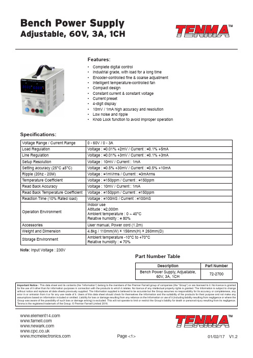
TMTM Page <1>V1.201/02/17Bench Power Supply Adjustable, 60V, 3A, 1CHFeatures:• Complete digital control• Industrial grade, with load for a long time• Encoder-controlled fine & coarse adjustment• Intelligent temperature-controlled fan• Compact design• Constant current & constant voltage• Current preset• 4-digit display• 10mV / 1mA high accuracy and resolution• Low noise and ripple• Knob Lock function to avoid improper operation Specifications:Voltage Range / Current Range0 - 60V / 0 - 3ALoad Regulation Voltage : ≤0.01% +2mV / Current : ≤0.1% +5mA Line Regulation Voltage : ≤0.01% +3mV / Current : ≤0.1% +3mA Setup Resolution Voltage : 10mV / Current : 1mASetting accuracy (25°C ±5°C)Voltage : ≤0.5% +30mV / Current : ≤0.5% +10mA Ripple (20hz - 20M)Voltage : ≤1mVrms / Current : ≤3mArms Temperature Coefficient Voltage : ≤150ppm / Current : ≤150ppmRead Back Accuracy Voltage : 10mV / Current : 1mARead Back Temperature Coefficient Voltage : ≤150ppm / Current : ≤150ppm Reaction Time (10% Rated load)Voltage : ≤100mS / Current : ≤100mSOperation Environment I ndoor useAltitude : ≤2,000mAmbient temperature : 0 ~ 40°C Relative humidity : ≤ 80%Accessories U ser manual, Power cord (1.2m)Weight and Dimension 4.8kg / 110mm(W) × 156mm(H) × 260mm(D)Storage Environment A mbient temperature -10°C to +70°CRelative humidity : ≤ 70%Part Number TableDescription Part NumberBench Power Supply, Adjustable,60V, 3A, 1CH72-2700Important Notice : This data sheet and its contents (the “Information”) belong to the members of the Premier Farnell group of companies (the “Group”) or are licensed to it. No licence is granted for the use of it other than for information purposes in connection with the products to which it relates. No licence of any intellectual property rights is granted. The Information is subject to changewithout notice and replaces all data sheets previously supplied. The Information supplied is believed to be accurate but the Group assumes no responsibility for its accuracy or completeness, any error in or omission from it or for any use made of it. Users of this data sheet should check for themselves the Information and the suitability of the products for their purpose and not make any assumptions based on information included or omitted. Liability for loss or damage resulting from any reliance on the Information or use of it (including liability resulting from negligence or where the Group was aware of the possibility of such loss or damage arising) is excluded. This will not operate to limit or restrict the Group’s liability for death or personal injury resulting from its negligence. Tenma is the registered trademark of the Group. © Premier Farnell Limited 2016.Note: Input Voltage : 230V。
电源供应器说明书
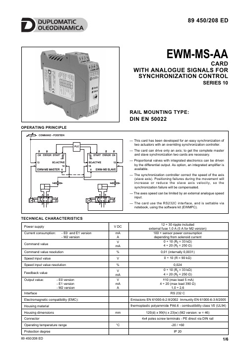
EWM-MS-AACARDWITH ANALOGUE SIGNALS FOR SYNCHRONIZATION CONTROLSERIES 10OPERATING PRINCIPLE89 450/208 EDRAIL MOUNTING TYPE:DIN EN 50022TECHNICAL CHARACTERISTICS1 - IDENTIFICATION CODEAnalog command value Analog feedback valueSeries No. (from 10 to 19 sizes and mounting dimensions remain unchanged)Digital card for closed loop systems DIN EN 50022 rail mounting Master and slave control E W M -MS -A A /10Output value:E0= voltage 0 ÷ ±10V (standard )E1= current 4 ÷ 20 mAM2= embedded power amplifier2.3 - Command valueThe card accepts analogue input. The command value must be 0 ÷ 10 V (R I = 33 kΩ) or 4 ÷ 20 mA. (R I = 250Ω)2.4 - Input feedback valuesThe card accepts analogue feedback input. The feedback value can be 0 ÷ 10 V (R I = 33 kΩ) or 4 ÷ 20 mA (R I = 250Ω). The sensor parameters are settable via software (see parameters table).2.5 - Command speed inputThe card accepts the command speed input with value 0 ÷ 10 V (R = 90 kΩ)2.6 - Output valuesThe card is designed for two type of output values, voltage ±10V (E0version) or current 4 ÷ 20 mA (E1 version); standard output value is E0 type. The embedded power stage is available on version M2 and it is adjustable via software, from 1 to 2,6 A.2.7 - Digital OutputTwo digital output are available, INPOS and READY, and their signals are displayed from the LEDS. As common potential 0V used (PIN 4) Low level <4 High Level >10.3 - LED FUNCTIONSThere are two LED on the card: GREEN and YELLOW.GREEN: Shows if the card is ready.ON - The card is suppliedOFF - No power supply or the ENABLE parameter is inactive FLASHING - Failure detected (internal or 4 ÷ 20 mA). Only if theparameter SENS is ON YELLOW: Is the signal of the control error monitoring. ON - No control errorOFF - Error detected, depending of a parameter error.The structure of the synchronisation controller was deduced from our positioning modules. The positioning function is controlled by the input PIN 13 (target position of the axis) and PIN 14 (actual position of the axis).With input PIN 6 (normally the sensor of the master axis) the actual position of the other axes is given to the module.SC MODE: With the SC active, the synchronisation controller is overriding the position control process. When the actual position of the master axis is given to the slave axis (sc = active), all slave axes will follow the master axis.In case of two axes, the position information can be linked crosswise from PIN 14 to PIN 6. The modes are master/master (both SC inputs are active), master/slave with selectable master function by deactivating of the SC input or independent positioning by deactivation of both SC inputs and separate command positions at PIN 13. The function of the STATUS output is - depending on SC input - in position signal (failure between PIN 13 and 14) or synchronisation error signal (failure between PIN 6 and PIN 14).For a reliable function of the synchronisation control the speed should be limited to app. 70/80% of maximum speed. The slave axis must be able to increase the speed against the master axis to compensate position failures.NOTE: By using positioning sensors with current input (4…20mA) PIN 6 of the slave and with PIN 14 of the master are connected parallel. DIL switches are removed; the right current input is set automatically.2 - FUNCTIONAL SPECIFICATIONS2.1 - Power supplyThis card is designed for 12 to 30 VDC (typical 24 V) of a power supply. This power supply must correspond to the actual EMC standards.All inductivities at the same power supply (relays, valves) must be provided with an over voltage protection (varistors, free-wheel diodes).It is recommended to use a regulated power supply (linear or switching mode) for the card supply and the sensors.NOTE: in the type M2 the value of the power supply voltage on the card must not be lower than the rated working voltage of the solenoid to be controlled.2.2 - Electrical protectionsAll inputs and outputs are protected against overvoltage and have filters.NOTE: one card per axis is needed. To synchronize 2 axes, 2 cards are needed.4 - ADJUSTMENTSOn the EWM card family, the adjustment setting is possible only via software. Connecting the card to the PC, the software automatically recognises the card model, and shows a table (see example below in the page) with all the available parameters, with their commands, the default setting, the measuring unit and an explanation of the command and its uses.The parameters changes depending on the card model, and they are fully described in the Overhaul manual.5 - INSTALLATIONThe card is designed for rail mounting type DIN EN 50022.The wiring connections are on the terminal strip located on the bottom of the electronic control unit. It is recommended to use cable sections of 0.75 mm2, up to 20 m length and of 1.00 mm2up to 40m length, for power supply and, for M2 version, for solenoid connections. For other connections it is recommended to use cables with a screened sheath connected to earth only on the card side.NOTE 1To observe EMC requirements it is important that the control unit electrical connection is in strict compliance with the wiring diagram.As a general rule, the valve and the electronic unit connection wires must be kept as far as possible from interference sources (e.g. power wires, electric motors, inverters and electrical switches).In environments that are critical from the electromagnetic interference point of view, a complete protection of the connection wires can be requested.7 - WIRING DIAGRAMPIN 1READY output.General operationality, ENABLE is active and there is no sensor error (by use of 4÷20 mA sensors). This output corresponds with the green LED.PIN 2STATUS output.Monitoring of the control error (INPOS). Depending on the INPOS command, the status output will bedeactivated, if the position difference is greater then the adjusted window. If SC-ACTIVE (pin 5) is on, this output is used to monitor the synchronization error.The output is only active if START = ON.PIN 5SC-ACTIVE:The synchronisation controller is activated. If this input is not activated, the system works as a normal positioning controller.PIN 7START input:The positioning controller is active; the external analogue command position is taken over as command value. If the input is switched off during movement, the command position is set to the actual position plus a defined emergency deceleration strokePIN 8ENABLE input:This digital input signal initializes the application. Theanalogue output is active and the READY signal indicates that all components are working correctly. Target position is set to actual position and the drive is closed loop controlled.PIN 6Actual (feedback) value (K) of the master axisrange 0÷100% corresponds to 0 ÷ 10V or 4 ÷20 mA PIN 9/10External command speed (V),range 0 ÷ 100 % corresponds to 0 ÷ 10 VPIN 13Command position (W),range 0 ÷ 100% corresponds to 0 ÷ 10V or 4 ÷ 20 mA PIN 14Actual (feedback) value (X),range 0 ÷ 100% corresponds to 0 ÷ 10V or 4 ÷ 20 mAPIN 15/16Differential output (U)± 100% corresponds to ± 10V differential voltage,optionally (E1 version) current output ±100%corresponds to 4 ÷ 20 mA (PIN 15 to PIN 12)DIGITAL INPUT AND OUTPUT ANALOGUE OUTPUT ANALOGUE INPUT 6 - SOFTWARE KIT EWMPC/10 (code 3898401001)The software kit comprising a USB cable (2.70 mt length) to connect the card to a PC or notebook and the software.During the identification all information are read out of the module and the table input will be automatically generated.Some functions like baud rate setting, remote control mode, saving of process data for later evaluation are used to speed up the installation procedure.The software is compliant with Microsoft XP ®operating systems.8 - CARD BLOCK DIAGRAM9 - AVAILABLE OUTPUT VALUE VERSIONS。
电力设备使用说明书
电力设备使用说明书1. 前言本电力设备使用说明书旨在提供全面的使用指导和操作规范,确保用户能够正确、安全地使用电力设备。
在使用本设备前,请认真阅读本说明书,并按照要求进行操作。
2. 设备概述2.1 设备名称:电力设备2.2 设备型号:[型号]2.3 主要组成部分:[主要组成部分]3. 设备安装3.1 环境准备:1) 确保安装场所符合相关安全规范;2) 检查电源电压是否符合设备要求。
3.2 安装步骤:1) 将设备放置在水平坚实的基础上;2) 按照设备连接图将各部件正确连接;3) 检查连接紧固情况,确保无松动现象。
4. 设备操作4.1 开机准备:1) 检查设备开关及电源线是否正常;2) 确保附近无易燃、易爆等物品。
4.2 开机步骤:1) 将设备接通电源;2) 检查电源指示灯,确保正常。
4.3 正常操作:1) 根据设备使用要求,选择相应的操作模式;2) 操作时需轻拿轻放,避免猛拉猛扯,以免损坏设备;3) 如遇异常情况,请及时停止使用并联系售后服务。
5. 设备维护5.1 日常维护:1) 定期清洁设备外壳及内部;2) 检查设备连接部件,如有松动应及时紧固。
5.2 预防性维护:1) 按照操作手册进行定期维护和保养;2) 定期更换易损件,确保设备正常运行。
5.3 故障处理:1) 如发生故障,请立即停止使用,并在危险被排除前不得重启设备;2) 如无法自行解决问题,请联系售后服务。
6. 注意事项6.1 安全事项:1) 在操作设备前,请确保已理解并掌握相关安全操作规程;2) 禁止未经授权人员进行设备操作。
6.2 电源要求:1) 请使用符合国家标准的电源;2) 请确保设备接地可靠。
6.3 防护措施:1) 使用设备时,请穿戴好必要的防护用品,确保人身安全;2) 长时间操作设备时,需注意防止眼睛疲劳。
7. 售后服务7.1 服务电话:[电话号码]7.2 售后保修期:根据实际情况而定,请咨询售后服务人员。
8. 结束语感谢阅读本电力设备使用说明书,请严格按照操作要求使用该设备,确保人身和财产安全。
电源设备说明书.pdf_1702137441.0057502

UK: +44 (0)1384 842211 France: +33 (0)1 4305 8680 Germany: +49 (0)6621 50570 Netherlands: +31 (0)24 372 3210•Current share on all outputs with ratingsof 10 A or greater•Remote sense on all outputs with ratingsgreater than 2 A•Overload protection on all outputs•Voltage adjustment on all outputs•Margining on all single output modules•Input-OK-signal and status indicator LED•Global DC OK signal and status indicator LED•Global and individual module inhibits/enable• 1 year warranty•Forced air cooling, field replaceable fan•Isolated 5 V bias voltage•Power factor correction•IEC EN61000-3-2 harmonic distortion compliance•CISPR 22, EN55022 Curve Bconducted / radiated EMI•European CE Mark requirements•Optional VME timing and system DC OK module•Low leakage option for medical applications•Immunity - EN61000 -4, -2, -3, -4 & -5 Level 3Operating temperature: -20°C to 50°C (start @ 0°C)(derate each output linearly to 50% at 70°C)(-20°C to 40°C max. with rear air option)Shock/Vibration: Mil-Hdbk 810EHumidity: 95% non-condensingStorage temperature: -40°C to +85°CT emperature coefficient: 0.02% per °CCooling:Internal DC fan (Field replaceable)(P/N 73-688-0001)•UL UL1950•CSA CSA22.2 No. 234 Level 5•IEC IEC950, Class 1•VDE EN60950,•BABT Compliance to EN 60950, BS 7002•CB Certificate and report •CE MarkMP8-3E-1L-1L-4NN-00..................................800 W total MP1-2Q-1D-1E-1L-1N-LLE-00......................1000 W totalMP6-3E-1E-4LL-0M ........................................600 W totalMP4-1E-1Q-1Q-LLE-00..................................400 W totalFrequency ..............................47-440 Hz Inrush current.........................40 A peak max.Efficiency................................70-80% typ. @ full case load Power factor ...........................0.99 typ. meets EN61000-3-2T urn-on time...........................AC on 1.5 sec typ.,Inhibit / Enable 150 ms typ.EMI filter standard..................CISPR 22EN55022 Level “B ”EMI filter (low leakage option)..CISPR 22EN55022 Level “A ”Leakage current standard......2.0 mA max. @ 240 VAC Leakage current (low leakage option)...............300 µA max. @ 240 VAC Radiated EMI .........................CISPR 22EN55022 Level “B ”Holdover storage....................20 ms minimum (independent of input VAC)AC OK....................................>5 ms early warning min. before outputs loose regulation Full cycle ride thru (50 Hz)Harmonic distortion ................Meets EN61000-3-2Isolation..................................Meets EN60950Global Inhibit/Enable..............TTL, Logic “1” and Logic “0”Input fuse (internal)................MP4: 10 A MP6: 15 A MP8: 20 A MP1: 20 A Warranty.................................1 year Power Derating Curve %Rated Total Case Load Normal Air Flow 30204060801003540455055606570TA – Ambient Temperature – °C50501Ripple.....................................RMS: 0.1% or 10 mV ,whichever is greaterPk-Pk: 1.0% or 50 mV ,whichever is greaterBandwidth limited to 20 MHzDynamic response .................<2% or 100 mV , with 25%load step.Recovery time ........................T o within 1% in <300 µsec.Overcurrent protection ...........Single, main of dual outputmodule 105-120% of ratedoutput current.Aux output of dual outputmodule 105-140% of ratedoutput current.T riple output module InternallyprotectedShort circuit protection ...........Protected for continuous shortcircuit. Recovery is automaticupon removal of shortOvervoltage protection...........Single output modules(measured at sense 2-5.5 V 122-134%connection)6-60 V 110-120%Dual output module2-6 V 122-134%8-28 V 110-120%T riple output module.No overvoltage protectionprovided. Recycle the AC inputvoltage to reset OVP circuitReverse voltageprotection ...............................100% of rated output currentThermal protection.................All outputs disabled wheninternal temp exceeds safeoperating range. >5 ms warning(AC OK signal) before shutdownRemote sense........................Up to 0.5 V total dropSingle wire parallel.................Current share to within 2% oftotal rated current 2DC OK....................................-2% to -8% of nominal for anymonitored output 2Minimum load.........................Not required on single or tripleoutput modules. 10% requiredon main of dual outputmodules 3HousekeepingBias voltage ............................******************whenever AC input is appliedModule inhibit.........................TTL, isolated, singles and dual(both outputs) onlySwitching frequency...............250 kHzOutput/Output isolation ..........>1 MegohmVME signal option board........POR signalNotes:1 Single output modules only.2 Single and main of dual output modules only.3 Contact factory for optional preload if required.MVP Series REV 25.10.00UK: +44 (0)1384 842211 France: +33 (0)1 4305 8680 Germany: +49 (0)6621 50570 Netherlands: +31 (0)24 372 321012345*For custom parallel configurations, contact Astec.Slot 1MP SINGLE OUTPUTSTotalOutput Size Model Number Power(Volts/Amps)(inches)360 W2 / 180 2.5 x 5 x 10MP4-3A-2A-30400 W5 / 80 2.5 x 5 x 10MP4-3E-00 - 429600 W2 / 275 2.5 x 8 x 11MP6-3A-3A-1A-90600 W5 / 120 2.5 x 5 x 11MP6-3E-00600 W48 / 12.5 2.5 x 5 x 11MP6-3W-00800 W5 / 160 2.5 x 7 x 10MP8-3E-2E-30 - 415800 W48 / 16.6 2.5 x 7 x 10MP8-3W-1W-301000 W 5 / 200 2.5 x 8 x 11MP1-3E-3E-30 - 404MULTIPLE OUTPUTSTotalOutput 1Output 2Output 3Output 4Output 5Output 6Size Model Number Power(Volts/Amps)(Volts/Amps)(Volts/Amps)(Volts/Amps)(Volts/Amps)(Volts/Amps)(inches)400 W5 / 60 3.3 / 3512 / 112 / 112 / 1— 2.5 x 5 x 10MP4-2E-1D-LLL-00400 W24 / 1512 / 17 5 / 35——— 2.5 x 5 x 10MP4-2Q-1L-1E-00400 W5 / 6012 / 1712 / 10 5 / 10—— 2.5 x 5 x 10MP4-2E-1L-4LE-00400 W5 / 3512 / 10 3.3 / 1012 / 112 / 1 5 / 2 2.5 x 5 x 10MP4-1E-4LD-LLE-00600 W3 / 60 5 / 6012 / 1012 / 4—— 2.5 x 5 x 11MP6-2C-2E-4LL-00600 W5 / 12012 / 1712 / 10 5 / 10—— 2.5 x 5 x 11MP6-3E-1L-4LE-00600 W12 / 30 5 / 35———— 2.5 x 5 x 11MP6-2L-1E-00800 W36 / 16.624 / 4 5 / 1012 / 1012 / 4— 2.5 x 7 x 10MP8-3U-4QE-4LL-00800 W5 / 120 3.3 / 3512 / 1712 / 1012 / 4— 2.5 x 7 x 10MP8-3E-1D-1L-4LL-00800 W15 / 20 5 / 3515 / 1424 / 8.515 / 8 5 / 10 2.5 x 7 x 10MP8-2N-1E-1N-1Q-4NE-00800 W2 / 180 5 / 60———— 2.5 x 7 x 10MP8-3A-2A-2E-301000 W 3.3 / 120 5 / 120———— 2.5 x 8 x 11MP1-3D-3E-00112233V11V21V11V21V312 VA 35A 60 A 120 A —10 A —— 2 A 2.2 VB 35 A 60 A 120 A —10 A —— 2 A 3 VC 35A 60 A 120 A —10 A —— 2 A 3.3 VD 35 A 60 A 120 A —10 A —— 2 A 5 VE 35A 60 A 120 A 10 A 10 A —— 2 A 5.2 VF 35 A 60 A 115 A —10 A —— 2 A 5.5 VG 34 A 58 A 109 A —10 A —— 2 A 6.0 VH 23 A 42 A 78 A —10 A —— 2 A 8.0 VI 20 A 36 A 68 A —— 1 A 1 A 1 A 10 VJ 18 A 32 A 60 A —— 1 A 1 A 1 A 11 VK 17 A 31 A 54.5 A —— 1 A 1 A 1 A 12VL 17A 30 A 50 A 10 A 4 A 1 A 1 A 1 A 14 VM 14 A 21 A 40.5 A 9 A 4 A 1 A 1 A 1 A 15 VN 14 A 20 A 39 A 8 A 4 A 1 A 1 A 1 A 18 VO 11 A 19 A 33.3 A ———0.5 A 0.5 A 20 VP 10.5 A 18 A 30 A ———0.5 A 0.5 A 24 VQ 8.5 A 15 A 23.5 A 4 A 2 A —0.5 A 0.5 A 28 VR 6.7 A 11 A 21.4 A 3 A 2 A —0.5 A 0.5 A 30 VS 6.5 A 11 A 20 A —————33 VT 6.2 A 10.9 A 18.2 A —————36 VU 5.8 A 10 A 16.6 A —————42 VV 4.2 A 7.5 A 12.5 A —————48 VW 4.0 A 7.5 A 12.5 A —————54 VX 3.7 A 6.0 A 11 A —————60 VY 3.5 A 6.0 A 10 A —————Non-stdZ 2.4V-2.7V3560120—10——23.6V-4.5V3560120—10——26.6V-9.2V203668104——18.8V-9.0V183260104——1Notes:1 T akes up one slot.2 T akes up two slots.3 T akes up three slots.MVP Series REV 25.10.00Notes:1T otal Loading not to exceed 36 W.2No Module Code required.2Triple Output Example 112 V @ 1 A 1;********;Module Code (always 4)Dual Output Example 112 V @ 10 A;5 V @ 10 A Single Output Example5 V @ 60 AJ1 CONTROL CONNECTORPin No.Function J1-1Input AC OK - “Emitter ”J1-2Input AC OK - “Collector ”J1-3Global DC OK - “Emitter ”J1-4Global DC OK - “Collector ”J1-5Spare J1-6Global Inhibit/Optional Enable Logic “0”J1-7Global Inhibit/Optional Enable Logic “1”J1-8Global Inhibit/Optional Enable Return J1-9SELV 5V Housekeeping J1-10SELV 5V Housekeeping Return CONTROL SIGNAL INFORMATION, J1 CONTROL CONNECTOR Pin No.Function 1+ Remote Sense single or dual o/p main 2Remote Margin / V . Program single o/p 3Margin High single o/p 4- Remote Sense / Margin Low single or dual o/p main 5Spare 6Module, Isolated Inhibit single or dual o/p 7Module Inhibit return single or dual o/p 8Current Share (SWP)single or dual o/p main 9+ Remote Sense V2dual o/p, single is spare 10- Remote Sense V2dual o/p, single is spareNotes:1T otal Loading not to exceed 144 W.2V1 output of 5V from dual is onlyavailable if output V2 is 6V or less.UK: +44 (0)1384 842211 France: +33 (0)1 4305 8680 Germany: +49 (0)6621 50570 Netherlands: +31 (0)24 372 32104 400 6 600N O T E S1.Input: Barrier type. Three No. 6-32 B.H. screws (0.375” centers). Max torque: 6 in-lbs. (0.67 N-m).2.Control connectors: (J1 and J2) 10 position housing, gold plated contacts. Mates with Molex 90142-0010 housing with 90119-2110 crimp contacts(Molex C - Grid III Series) or AMP Model number 87977-3 with 87309-8 pins.Connector kit includes mating connector and 10 pins, Astec part #70-841-004.3.Chassis material: aluminum with chemical film coating. (Conductive)4.All dimensions are in millimeters and inches and are typical.5.Customer mounting -3 sides M4, bottom also includes 8-32 mounting holes. Max. penetration is 0.150” (3.8mm). Max. torque: 5in-lbs.6.Output module connections: All single O/P modules are M4 x 8mm screws. Max. torque: 10in-lbs.Dual O/P module is M3 x 8mm screws. Max. torque: 5 in-lbs.T riple O/P module is .045” square pins on .156” centers. (Mates with Molex 09-50-8063 or equivalent.)+-+-+.0-.5254.0+.00-.0210.00 3.7.15TYP 19.05.750+.0-.563.5+.00-.022.503.5.14(TYP)M4 MTG HOLES 4 PL MOUNTING HOLES DIMENSIONS IDENTICAL ON BOTH SIDES 17.3 1.0.68 .04171.456.75038.101.50012.70.500MP4+.0-.5279.4+.00-.0211.00MP68 800MVP Series N O T E S1.Input: Barrier type. Three No. 6-32 B.H. screws (0.375” centers). Max torque: 6 in-lbs. (0.67 N-m).2.Control connectors: (J1 and J2) 10 position housing, gold plated contacts. Mates with Molex 90142-0010 housing with 90119-2110 crimp contacts (Molex C - Grid III Series) or AMP Model number 87977-3 with 87309-8 pins.Connector kit includes mating connector and 10 pins, Astec part #70-841-004.3.Chassis material: aluminum with chemical film coating. (Conductive)4.All dimensions are in millimeters and inches and are typical.5.Customer mounting -3 sides M4, bottom also includes 8-32 mounting holes. Max. penetration is 0.150” (3.8mm). Max. torque: 5in-lbs.6.Output module connections: All single O/P modules are M4 x 8mm screws. Max. torque: 10in-lbs.Dual O/P module is M3 x 8mm screws. Max. torque: 5 in-lbs.T riple O/P module is .045” square pins on .156 centers. (Mates with Molex 09-50-8063 or equivalent.)REV 25.10.00UK: +44 (0)1384 842211 France: +33 (0)1 4305 8680 Germany: +49 (0)6621 50570 Netherlands: +31 (0)24 372 32101 1000Weight: MP1 Case: 2.25kg. • 36 W T riple: 0.22kg. • 210 W Single: 0.27kg. • 360 W Single 0.45kg. • 600 W Single: 0.9kg.• 144 W Dual: 0.6kg.SINGLE OUTPUT MODULES1 slot, 210 watt2 slot, 360 watt3 slot, 600 wattN O T E S 1.Input: Barrier type. Three No. 6-32 B.H. screws (0.375” centers).Max torque: 6 in-lbs (0.67 N-m).2.Control connectors: (J1 and J2) 10 position housing, gold plated contacts. Mates with Molex 90142-0010 housing with 90119-2110crimp contacts (Molex C - Grid III Series) or AMP Model number 87977-3 with 87309-8 pins.Connector kit includes mating connector and 10 pins, Astec part #70-841-004.3.Chassis material: aluminum with chemical film coating. (Conductive)4.All dimensions are in millimeters and inches and are typical.5.Customer mounting -3 sides M4, bottom also includes 8-32mounting holes. Max. penetration is 0.150” (3.8mm). Max. torque:5in-lbs.6.Output module connections: All single O/P modules are M4 x 8mm screws. Max. torque: 10in-lbs.Dual O/P module is M3 x 8mm screws. Max. torque: 5 in-lbs.T riple O/P module is .045” square pins on .156 centers. (Mates with Molex 09-50-8063 or equivalent.)Rev 25.10.00MVP Series+V1-V2+V2-V3+V3-DUAL OUTPUTMODULE1 slot, 144 wattTRIPLE OUTPUT MODULE 1 slot, 36 watt。
- 1、下载文档前请自行甄别文档内容的完整性,平台不提供额外的编辑、内容补充、找答案等附加服务。
- 2、"仅部分预览"的文档,不可在线预览部分如存在完整性等问题,可反馈申请退款(可完整预览的文档不适用该条件!)。
- 3、如文档侵犯您的权益,请联系客服反馈,我们会尽快为您处理(人工客服工作时间:9:00-18:30)。
(6)解除电流限制开关。
2.定电压/定电流之交越(CROSSOVER)特性:
此系列直流电源供应器的工作特性为定电压/定电流自动交越型式。这可允许对负载变化的反应从定电流到定电压之连续转变。定电压和定电流之交点称之为交越点。
三、操作說明:
24.“S+” Terminal正极感应端子。
25.接地。
二、模式設定及操作模式說明:
1.设定限流值:
(1)首先确定电源装置所需要供给的最大安全电流值。
(2)按下电流限制开关。
(3)从零开始旋转粗调电压控制旋钮直到CC指示灯亮起。
(4)调整电流控制旋钮以取得所需的最大电流限制,从电流表读取电流有效值。
3.儀器與治具連接應注意插線接口相應位置;
4.切勿使用磨沙布或溶解劑清潔儀器,以免破壞儀器的外殼;
5.儀器內部設定切勿亂調。一﹑面板介紹及說Fra bibliotek﹕前面板
图一
后面板
图二
1.CV Indicator打开电源,在定电压操作模式时,灯会亮。
Indicator在定电流操作模式时,灯会亮。
3.Voltage输出电压调整旋钮。
4.Current输出电流调整旋钮。
5.“+” Output terminal正极输出端子(红色端子)。
17.“L” Terminal火线输入端。
18.“N” Terminal地线输入端。
19.GND Terminal接地与机壳地。
20.Cooling Fan排出热气以避免机气过热而损坏。
21.“S-” Terminal负极感应端子。
22.“-” Terminal负极输出端子。
23.“+” Terminal正极输出端子。
11.Current Limit Switch限电流值设定的开关。
12.OVP Switch按下此键,电压表会显示过电压保护设定值。
13.OVP Adjust过电压保护设定值的调整。
14.Output Switch输出电压控制键。
15.Output Indicator打开输出,灯会亮。
16.Caution High Voltage高压危险标志。
6.“GND” terminal接地与机壳地(绿色端子)。
7.“-” Output terminal负极输出端子(黑色端子)。
8.Voltmeter显示输出电压(数字式或模拟式电表)。
9.Ammeter显示输出电流(数字式或模拟式电表)。
10.Power Control电源开/关控制及过电压/过电流跳脱用开关。
1.按下“POWER"鍵屏幕顯示電壓電流;
2.根據產品要求調節所需電壓、電流“VOLTAGE”、“CURRENT”;
3.按“+”、“-”極對應連接好相應治具后即可進行測試;
4.測試完畢后關閉電源電壓。
四、注意事項:
1.電源電壓110V/220V均可使用,切勿插錯電源以免燒壞儀器;
2.操作溫度:0~40℃,相對濕度不超過80%;