J761出入口阀使用说明书
伺服阀使用说明书

伺服阀使用说明书伺服阀是DEH控制系统中电液转换的关键元件,它可将电调装置发出的控制指令,转变成相应的液压信号,并通过改变进入油动机油缸液流的方向、压力和流量,来达到驱动阀门、控制机组的目的。
1 结构特点伺服阀是一个由力矩马达、两级液压放大及机械反馈所组成的系统。
第一级液压放大是双喷嘴挡板系统;第二级放大是滑阀系统。
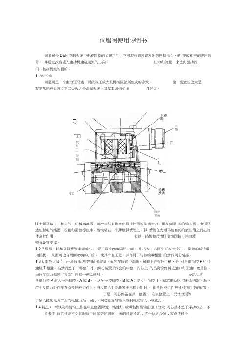
其基本结构如图1所示。
1.1 力矩马达:一种电气—机械转换器,可产生与电指令信号成比例的旋转运动,用在伺服阀的输入级。
力矩马达包括电气线圈、极靴和衔铁等组件。
衔铁装在一个薄壁弹簧管上,弹簧管在力矩马达和阀的液压段之间起流体密封作用。
衔铁、挡板和反馈杆刚性固接,并由薄壁弹簧管支撑。
1.2 先导级:挡板从弹簧管中间伸出,置于两个喷嘴端面之间,形成左、右两个可变节流孔。
衔铁的偏转带动挡板,从而可改变两侧喷嘴的开启,使其产生压差,并作用于与该喷嘴相通的滑阀阀芯端部。
1.3 功率放大级:由一滑阀系统控制输出流量。
阀芯在阀套中滑动,阀套上开有环行槽,分别与供油腔P和回油腔T相通。
当滑阀处于“零位”时,阀芯被置于阀套的中位;阀芯上的凸肩恰好将进油口和回油口遮盖住。
当阀芯受力偏离“零位”向任一侧运动时,导致油液从供油腔P流入一控制腔(A或B),从另一控制腔(B或A)流入回油腔T。
阀芯推动反馈杆端部的小球,产生反馈力矩作用在衔铁挡板组件上。
当反馈力矩逐渐等于电磁力矩时,衔铁挡板组件被移回到对中的位置。
于是,阀芯停留在某一位置。
在该位置上,反馈力矩等于输入控制电流产生的电磁力矩,因此,阀芯位置与输入控制电流的大小成正比。
1.4 特点:●衔铁及挡板均工作在中立位置附近,线性好●喷嘴挡板级输出驱动力大●阀芯基本处于浮动状态,不易卡住●阀的性能不受伺服阀中间参数的影响,阀的性能稳定,抗干扰能力强,零点漂移小2 工作原理:当力矩马达没有电信号输入时,衔铁位于极靴气隙中间,平衡永久磁铁的磁性力。
当有欲使调节阀动作的电气信号由伺服放大器输入时,力矩马达的线圈中有电流通过,产生一磁场,在磁场作用下,产生偏转力矩,使衔铁旋转,同时带动与之相连的挡板转动,此挡板伸到两个喷嘴中间。
小型单座阀门说明说明书
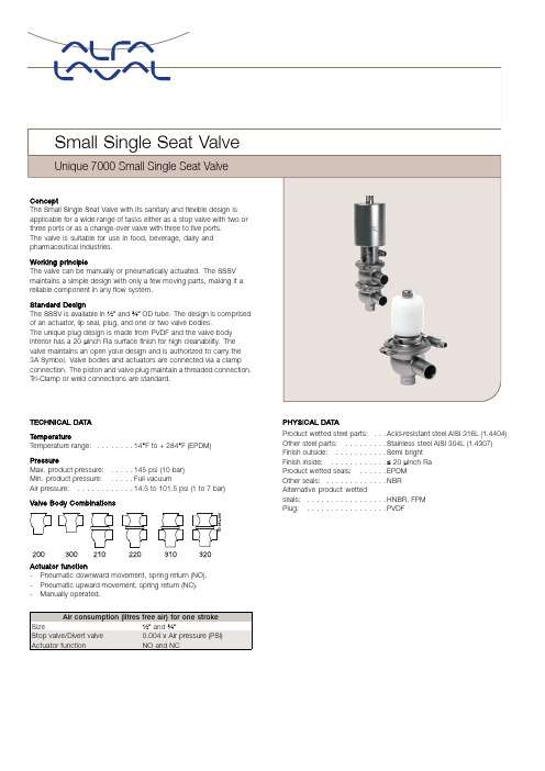
TECHNICAL DATATemperatureTemperature range:........14°F to+284°F(EPDM) PressureMax.product pressure:.....145psi(10bar)Min.product pressure:.....Full vacuumAir pressure:............14.5to101.5psi(1to7bar) Valve BodyCombinationsActuator function-Pneumatic downward movement,spring return(NO).-Pneumatic upward movement,spring return(NC).-Manually operated.Air consumption(litres free air)for one strokeSize½”and¾”Stop valve/Divert valve0.004x Air pressure(PSI)Actuator function NO and NCPHYSICAL DATAProduct wetted steel parts:...Acid-resistant steel AISI316L(1.4404)Other steel parts:.........Stainless steel AISI304L(1.4307)Finish outside:...........Semi brightFinish inside:............≤20µinch RaProduct wetted seals:......EPDMOther seals:.............NBRAlternative product wettedseals:.................HNBR,FPMPlug:.................PVDFOptionsA.3.1.B Certificate.B.Adapter for IndiTop,ThinkTop and ThinkTop Basic.C.Control and Indication:IndiTop,ThinkTop or ThinkTop Basic.D.Product wetted seals of HNBR or FPM.E.Surface finish external≤32µinch Ra.Dimensions(inch)Remote-controlledOD ODNominal Size½”¾“A1 6.78 6.74A27.067.17A37.888.24A48.168.67C 1.27 1.50OD0.500.75ID0.370.62t0.060.06E1 1.17 1.18E2 1.77 1.77F10.280.43F20.280.43H 2.24 2.24Weight(lbs)Stop valve 2.36 2.43 Weight(lbs)Change-over valve 3.00 3.11 (900-233)*Dimensions valid for both welding ends and clamp ends.Please note!Opening/closing time will be affected by the following:-The air supply(air pressure).-The length and dimensions of the air hoses.-Number of valves connected to the same air hose.-Use of single solenoid valve for serial connected airactuator functions.-Product pressure.Air Connections Compressed air:R1/8"(BSP),internalthread.Stop valve DivertManual stop valve ManualPressure drop/capacity diagramsvalveNote!For the diagrams the following applies:Medium:Water(68°F).Measurement:In accordance with VDI2173Pressure drop can also be calculated in CAS.Pressure drop can also be calculated with the following formula:Q=Kv x√∆pWhereQ=Flow(gallon/minute).Cv=gallon/minute at a pressure drop of1psi(see table above).∆p=Pressure drop in psi over the valve.WhereQ=Flow(gallon/minute).Cv=gallon/minute at a pressure drop of1psi(see table above).∆p=Pressure drop in psi over the valve.2.5"shut-off valve,where Cv=128(See table above).Q=Kv x√∆p160=128x√∆p(This is approx.the same pressure drop by reading the y-axis above)Pressure data for Small Single Seat Valveoooo 12345678A=Air P/Po=Product pressureTable1-Shut-off and change-over valves The table shows the approx.static pressure(p)in psi against which the valve can openValve size Actuator/Valve bodycombination and directionof pressureAirpressure(psi)PlugpositionDN/OD½”DN/OD¾”1NO Min.145Min.14529NO29-43.5NO43.5258NOMin.145Min.14529NC130.5-343.5NC Min.145Min.1454NC Min.145Min.145Table2-Stop and change-over valve.The table shows the approx.static pressure(p)in psi against which the valve can openValve size Actuator/Valve bodycombination and directionof pressureAirpressure(psi)PlugpositionDN/OD½”DN/OD¾”5NO Min.145Min.14529NO130.5-43.5NO Min.14587658NO-Min.145 729NC Min.145Min.1458NC Min.145Min.145ESE00368ENUS1505Alfa Laval reserves the right to change specifications without priornotification.ALFA LAVAL is a trademark registered and owned by Alfa LavalCorporate AB.©Alfa LavalHow to contact Alfa LavalContact details for all countriesare continually updated on our website. Please visit toaccess the information direct.。
进口调节阀中文版说明..

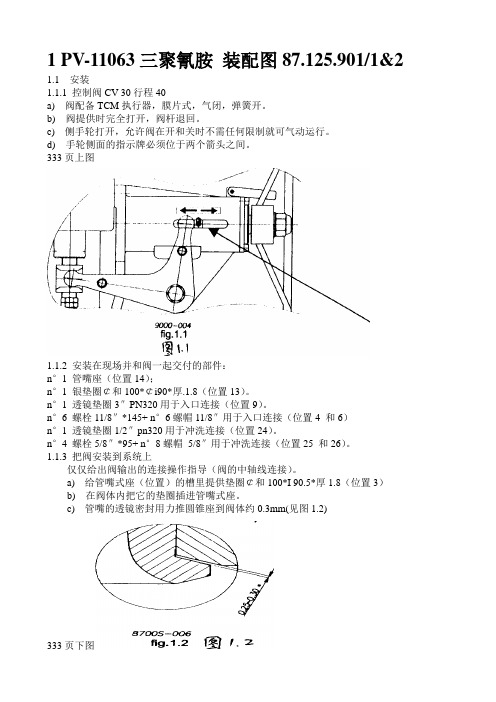
1 PV-11063三聚氰胺装配图87.125.901/1&2 1.1安装1.1.1 控制阀CV 30行程40a) 阀配备TCM执行器,膜片式,气闭,弹簧开。
b) 阀提供时完全打开,阀杆退回。
c) 侧手轮打开,允许阀在开和关时不需任何限制就可气动运行。
d) 手轮侧面的指示牌必须位于两个箭头之间。
333页上图1.1.2 安装在现场并和阀一起交付的部件:n°1 管嘴座(位置14);n°1 银垫圈¢和100*¢i90*厚.1.8(位置13)。
n°1 透镜垫圈3″PN320用于入口连接(位置9)。
n°6 螺栓11/8″*145+ n°6螺帽11/8″用于入口连接(位置4 和6)n°1 透镜垫圈1/2″pn320用于冲洗连接(位置24)。
n°4 螺栓5/8″*95+ n°8螺帽5/8″用于冲洗连接(位置25 和26)。
1.1.3 把阀安装到系统上仅仅给出阀输出的连接操作指导(阀的中轴线连接)。
a) 给管嘴式座(位置)的槽里提供垫圈¢和100*I 90.5*厚1.8(位置3)b) 在阀体内把它的垫圈插进管嘴式座。
c) 管嘴的透镜密封用力推圆锥座到阀体约0.3mm(见图1.2)333页下图d)用铁丝把阀出口和管口紧固,这样阀定位时管口不会退回;e)接阀相关的连接,并定位阀,注意不要小心擦伤阀体和管口之间的垫圈。
f)逐步地小心紧固对角相接的法兰螺帽。
g)阀内外之间的流体密封通过位于管口上的透镜垫圈来保证。
h)镀银垫圈(位置13)防止管口座和阀体之间的缝隙流体进入,这样在维护时拆卸方便。
i)1.1.4a) 把减压过滤器接到气源分配器上。
b) 减压过滤器最大压力必须不要超过8.96bar(130psi).c) 供气压力,也就是说过滤器出口压力,已调整到使阀可工作的压力。
它不能超过4.14bar(60psi).1.1.5 信号输入a) 选择的输入信号是4-20mA。
AZM 161SK_12 12RIT_024_B1 阀门拦锁说明书
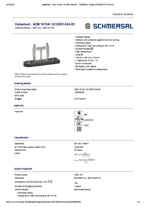
13.06.2016 05:48:44hDatasheet AZM 161SK12/12RIT024B1Solenoid interlock / AZM 161I / AZM 161IB1(Minor differences between the printed image and the original product may exist!)• Compact design• Interlock with protection against incorrect locking.• Individual coding• Coding level "High" according to ISO 14119• Doubleinsulated • High holding force • Long life• 130 mm x 90 mm x 30 mm • 1 Cable entry M 20 x 1.5• Screw connection• Emergency exit, lateral• Particularly suitable for sliding doorsOrdering detailsProduct type description AZM 161SK12/12RIT024B1Article number 103000236EAN code eCl@ss 27272603ApprovalApprovalBG USA/CAN CCCClassificationStandardsEN ISO 138491B 10d Normallyclosed contact (NC) 2.000.000Mission time 20 Y earsnoticeGlobal PropertiesProduct name AZM 161IStandardsEN 6094751, BGGSET19Compliance with the Directives (Y/N) Y es Number of actuating directions 3 pieceActive principle electromechanical Individual coding Coding level "High" according to ISO 14119Duty cycle Magnet 100 %Materials Material of the housings glassfibre reinforced thermoplastic, Plastic selfextinguishing, Material of the actuator Stainless steel Material of the contacts SilverHousing coating NoneWeight515 gMechanical dataDesign of electrical connection Screw connectionCable section Min. Cable section1 x 0,25 mm² Max. Cable section1 x 1.5 mm², flexibleMechanical life> 1.000.000 operationsnotice All indications about the cable section are including the conductorferrules.Emergency unlocking device (Y/N)Y esManual release (Y/N)NoEmergency release (Y/N)NoLatching force30 NPositive break force20 Npositive break travel10 mmClamping force F2000 NMax. Actuating speed2 m/sMinimum actuating radius150 mmActuating frequency max. 1000 / hAmbient conditionsAmbient temperature Min. environmental temperature−25 °C Max. environmental temperature+60 °CProtection class IP67 to IEC/EN 60529Electrical dataDesign of control element Normally open contact (NO), Opener (NC)Switching principle Creep circuit elementNumber of auxiliary contacts2 pieceNumber of safety contacts4 piecePower to unlock Y esPower to lock NoRated control voltage U s24 VAC/DCPower consumption max. 10 WRated impulse withstand voltage U imp4 kVRated insulation voltage U i250 VThermal test current I the6 AUtilisation category AC15: 230 V / 4 ADC13: 24 V / 2,5 AMax. fuse rating6 A gG Dfuse To DIN EN 602691ATEXExplosion protection categories for gases NoneExplosion protected category for dusts NoneMiscellaneous dataApplicationssliding safety guard,removable guard,hinged safety guardDimensionsDimensions of the sensor Width of sensor130 mm Height of sensor90 mm Length of sensor30 mmnoticeOn hinged guards, minimum actuating radius at 90° to the plane of the actuator 180 mmminimum actuating radius on hinged guards in line with the plane of the actuator 150 mmThe actuator is not available separately.The axis of the hinge should be 5 mm above the top edge of the safety switch and in the same plane Emergency exit• For cases of danger Actuation from within the hazardous areaIncluded in deliveryIncluded in delivery• Individually coded actuator• tamperproof screws• Slot sealing plugsDiagramNote Diagrampositive break NC contactactiveno activeNormallyopen contactNormallyclosed contactSwitch travel diagramNotes Switch travel diagramContact closedContact openSetting rangeBreak pointPositive opening sequence/ angleVS adjustable range of NO contactVÖ adjustable range of NC contactN after travelOrdering suffixThe applicable ordering suffix is added at the end of the part number of the safety switch. Order example: AZM 161SK12/12RIT024B11637...16370,3 µm goldplated contactsDocumentsOperating instructions and Declaration of conformity (en) 562 kB, 20.01.2016Code: mrl_azm161i_enOperating instructions and Declaration of conformity (jp) 767 kB, 12.04.2016Code: mrl_azm161i_jpOperating instructions and Declaration of conformity (nl) 511 kB, 15.08.2012Code: mrl_azm161i_nlOperating instructions and Declaration of conformity (da) 504 kB, 27.08.2012Code: mrl_azm161i_daOperating instructions and Declaration of conformity (de) 565 kB, 20.01.2016Code: mrl_azm161i_deOperating instructions and Declaration of conformity (pl) 589 kB, 06.04.2016Code: mrl_azm161i_plOperating instructions and Declaration of conformity (es) 444 kB, 09.03.2016Code: mrl_azm161i_esOperating instructions and Declaration of conformity (pt) 510 kB, 27.08.2012Code: mrl_azm161i_ptOperating instructions and Declaration of conformity (sv) 498 kB, 27.08.2012Code: mrl_azm161i_svOperating instructions and Declaration of conformity (cs) 586 kB, 19.04.2016Code: mrl_azm161i_csOperating instructions and Declaration of conformity (it) 562 kB, 19.04.2016Code: mrl_azm161i_itOperating instructions and Declaration of conformity (fr) 567 kB, 28.04.2016Code: mrl_azm161i_frEAC certification (ru) 809 kB, 05.10.2015Code: q_6040p17_ruImagesProduct photoDimensional drawing (miscellaneous)Dimensional drawing (miscellaneous)Actuating radiusActuating radiusK.A. Schmersal GmbH & Co. KG, Möddinghofe 30, D42279 WuppertalThe data and values have been checked throroughly. Technical modifications and errors excepted. Generiert am 13.06.2016 05:48:44h Kasbase 3.2.2.F.64I。
进口调节阀中文版说明
1 PV-11063三聚氰胺装配图87.125.901/1&2 1.1安装1.1.1 控制阀CV 30行程40a) 阀配备TCM执行器,膜片式,气闭,弹簧开。
b) 阀提供时完全打开,阀杆退回。
c) 侧手轮打开,允许阀在开和关时不需任何限制就可气动运行。
d) 手轮侧面的指示牌必须位于两个箭头之间。
333页上图1.1.2 安装在现场并和阀一起交付的部件:n°1 管嘴座(位置14);n°1 银垫圈¢和100*¢i90*厚.1.8(位置13)。
n°1 透镜垫圈3″PN320用于入口连接(位置9)。
n°6 螺栓11/8″*145+ n°6螺帽11/8″用于入口连接(位置4 和6)n°1 透镜垫圈1/2″pn320用于冲洗连接(位置24)。
n°4 螺栓5/8″*95+ n°8螺帽5/8″用于冲洗连接(位置25 和26)。
1.1.3 把阀安装到系统上仅仅给出阀输出的连接操作指导(阀的中轴线连接)。
a) 给管嘴式座(位置)的槽里提供垫圈¢和100*I 90.5*厚1.8(位置3)b) 在阀体内把它的垫圈插进管嘴式座。
c) 管嘴的透镜密封用力推圆锥座到阀体约0.3mm(见图1.2)333页下图d)用铁丝把阀出口和管口紧固,这样阀定位时管口不会退回;e)接阀相关的连接,并定位阀,注意不要小心擦伤阀体和管口之间的垫圈。
f)逐步地小心紧固对角相接的法兰螺帽。
g)阀内外之间的流体密封通过位于管口上的透镜垫圈来保证。
h)镀银垫圈(位置13)防止管口座和阀体之间的缝隙流体进入,这样在维护时拆卸方便。
i)注.如果拆开阀的出口连接,必须更换镀银垫圈(位置13)。
注意:为保证垫圈密封,有必要把阀安装到系统上,一致性紧固法兰螺帽,逐渐并对角紧固。
这样确保轴对正连接。
1.1.4a) 把减压过滤器接到气源分配器上。
b) 减压过滤器最大压力必须不要超过8.96bar(130psi).c) 供气压力,也就是说过滤器出口压力,已调整到使阀可工作的压力。
伺服阀使用说明书
伺服阀使用说明书伺服阀是DEH 控制系统中电液转换的关键元件,它可将电调装置发出的控制指令,转 变成相应的液压信号, 并通过改变进入油动机油缸液流的方向、压力和流量,来达到驱动阀门、控制机组的目的。
1结构特点伺服阀是一个由力矩马达、两级液压放大及机械反馈所组成的系统。
第一级液压放大是 双喷嘴挡板系统;第二级放大是滑阀系统。
其基本结构如图 1所示。
i.i 力矩马达:一种电气一机械转换器,可产生与电指令信号成比例的旋转运动,用在伺服 阀的输入级。
力矩马达包括电气线圈、极靴和衔铁等组件。
衔铁装在一个薄壁弹簧管上,弹 簧管在力矩马达和阀的液压段之间起流体密封作用。
衔铁、挡板和反馈杆刚性固接,并由薄壁弹簧管支撑。
1.2先导级:挡板从弹簧管中间伸出, 置于两个喷嘴端面之间, 形成左、右两个可变节流孔。
衔铁的偏转带动挡板, 从而可改变两侧喷嘴的开启, 使其产生压差,并作用于与该喷嘴相通 的滑阀阀芯端部。
1.3功率放大级:由一滑阀系统控制输出流量。
阀芯在阀套中滑动,阀套上开有环行槽,分 别与供油腔P 和回油腔T 相通。
当滑阀处于“零位”时,阀芯被置于阀套的中位;阀芯上 的凸肩恰好将进油口和回油口遮盖住。
当阀芯受力偏离“零位”向任一侧运动时, 导致油液 从供油腔P 流入一控制腔(A 或B ),从另一控制腔(B 或A )流入回油腔 T 。
阀芯推动反 馈杆端部的小球,产生反馈力矩作用在衔铁挡板组件上。
当反馈力矩逐渐等于电磁力矩时, 衔铁挡板组件被移回到对中的位置。
于是,阀芯停留在某一位置。
在该位置上,反馈力矩等 于输入控制电流产生的电磁力矩,因此,阀芯位置与输入控制电流的大小成正比。
1.4 特点: 衔铁及挡板均工作在中立位置附近 , 线性好 喷嘴挡板级输出驱动力大 阀芯基本处于浮动状态 , 不易卡住 阀的性能不受伺服阀中间参数的影响 , 阀的性能稳定 , 抗干扰能力强 , 零点漂移小 圃定节流口 F芯阀F駅肝—— 控轴畫的出逵电插2 工作原理:当力矩马达没有电信号输入时,衔铁位于极靴气隙中间,平衡永久磁铁的磁性力。
西门子、ABB、川仪、萨姆森、机械阀门阀门汇总说明

P2.4 SHUTOFF P2.5 RAMP⋀ P2.6 RAMP⋁
设定给定信号的最大值(预设为20mA) 选择调节特性曲线 设定阀门正反作用方式DIRECT正作用 ;reverse反作用 设定阀门开度阈值 降低开向速度 降低关向速度
4.ABB阀门定位器(参数菜单)
P6._MAN_ P6.0 MIN_VR ADJ手动 调整 P6.1 MAX_VR P6.2 ACTAUTOR P6.3 SPRNG_Y2 P6.4 ADJ_MODE P6.5 EXIT 手动设置阀门全关位置
手动设置阀门全开位置 选择执行器型式 设定执行器弹簧伸长时定位器返馈杆 旋转方向 选择自动调整所需检测的项目
退出到运行操作级
4.ABB阀门定位器(参数菜单)
P8._ANLG P8.0 MIN_RGE _OUT模拟 信号输出 阀位起始点电流值(默认为4mA)
P8.1 MAX_RGE P8.2 ACTION
4.ABB阀门定位器(参数菜单)
3.从第二组配置参数中选择阀门作用方式P2.3 按住MODE键 点击⇧键3次 显示器显示“P2.3 ACTION” 松开MODE键 4.更改阀门作用方式 点击⇧键选择“REVERSE” 5.切换至“P2.7 EXIT” 存储并退出(如软件版本是2.0 以上,则切换“P2.8 EXIT”) 按住MODE键 点击⇧键多次直至显示器显示“P2.7 EXIT” 松开MODE键 用⇧或⇩键选择 NV_SAVE 按住ENTER 键直到计数器倒计数结束后松开
4.ABB阀门定位器(操作界面及自整定)
4.ABB阀门定位器(执行机构)
4.ABB阀门定位器(按键说明)
1.切换至参数配置菜单 同时按住⇧和⇩键 点击ENTER键 等待3秒钟,计数器从3计数到0,松开⇧和⇩键 程序自动进入P1.0配置菜单
Parker P70 Series智能性能新效率模块式加载感应式阀门系列说明说明书

The P70 SeriesSmartperformanceNew efficiency for sequential applicationsModular Load Sensing ValvesSeries P70LSParker Hannifi n AB SE-501 78 BoråsTel.: +46 (0)33 700 52 00Fax: +46 (0)33 12 11 /euro_mcdBulletin HY17-8510-B1/UK 3 M 05/06 S&S© Copyright 2006Parker Hannifi n Corporation All rights reservedCommon features – P70 series:• Main pressure relief valve• Port relief valves with anti-cavitationfunction• Anti-cavitation valves • Application adapted spools • Pressure compensated spools • Load hold check valve• For single or multi-pump operationOptions vary for different valvesValve Pump fl ow Pressure Operation l/minbar Manual Pneumatic Hydraulic Electro-hydraulicP70CF 70 350 • • • •P70CP 90 350 • • • • P70LS90350••The ultimate cost/performance compromise!Open Centre technology taken to the limits!Lower running costs, longer service lifeThe unique P70LS solution with its built-in, intelligent load-sensing abilities will give you precise control, quick reactions and a higher overall system efficiency, resulting in lower noise and lower heat losses, and ultimately considerably lower fuel consumption and an extended service life. All this has been made possible through an ingenious adaptation of our existing mass market valve technology, reducing your time-to-market without compromising performance.Take the first step today!The new P70LS can also be a cost-reducing option to fully load sensing valves for less demanding functions in more complex systems. The P70LS technology is an ideal first step into the world of new functionality offered by Parker’s advanced load sensing technologies.TYPICAL APPLICATIONS: REFUSE VEHICLES • SKIP LOADERS • AGRICULTURAL MA CHINES • MEDIUM DUTY WHEEL LOADERS • PISTE MACHINES • FORK LIFTS • FORESTRY MACHINES • ETC.Often when designing mobile hydraulic systems, cost considerations override desired performance, functionality and ergonomics. A high-tech load sensing system would be better in many ways, but the budget just won’t stretch that far.That is when Parker’s new P70LS valve comes to the rescue. Based on a proven, economical, open centre thoroughbred technology, it enables many of the advantages of a load sensing system at a fraction of the cost.Load sensing advantages on a budgetWithout separate compensator, the P70LS achieves simultaneous function operation capabilities through our extensive spool design know-how for pilotoperated valves. The P70 in its load sensing version is a top-of-the-line complement to existing open centre based machines on the market.Copy spools– avoiding micro sinkingPressure com- pensated load signal drain for faster response• Higher productivity• Load-sensing at a fraction of the cost• Based on proven open centre technology• Reduces fuel costs significantly • Better manœuvring precision • Easy to install• M odular design – expandable and upgradeable•P erfect for sequential applications •A global product with global back-up •Simplified cirquit lay-out �������������������������������������Port relief valves with quick responseModular design – expandable and upgradableRobust mainrelief valveMachined land edges for higher precisionPressure compensatedspools for better ergonomics and smoother manœuvring。
六通阀中文说明书

Rheodyne 操作说明型号7725i ,9725i ,3725i-038,3725i ,和9125手动进样器1.0 描述型号7725i ,9725i ,3725i-038,3725i ,和9125 是样品通过阀前面的内嵌式针道被载入的六通阀。
型号7725i 和3725i-038是不锈钢的,9125是PEEK 制成的。
型号3725i-038和3725i 是接收1/8``量的准备阶段的进样器。
除了进行准备阶段的应用之外,准备阶段的进样器和它们相应的分析阶段的进样器是一样的。
带有“i ”的型号包含一个内嵌的侧向开关。
侧向开关的具体说明参照10.3。
图1说明了阀的流程图(型号9125不包含文中提到的MBB 阀)。
这些周期在阀的定子中循环。
深色槽是转子密封垫的连接部分。
流动通道体现了MBB 阀的设计。
MBB 阀的具体的剖面图如图2所示。
样品环在载入位置通过针道被装载。
转动手柄60度,阀从LOAD 档开到INJECT 档。
在INJECT 档,流动相和样品通过环到达柱的顶端。
MBB 阀从LOAD 档开到INJECT 档过程中,阀结构允许连续的流动。
流动相从转子密封槽和MBB 槽通道中连续的流动直到转动停止。
参见图1和图2。
位置1 (载入)图表1:带有MBB 阀的进样器型号9125 是不带有MBB 阀的相同设计。
图2 MBB 阀的轴剖面样品环泵柱针道排出 排出定子正面密封垫里的MBB 阀通道 MBB 孔连接MBB 阀通道和定子的前端位置2 (进样)样品环泵柱排出排出针道转子密封槽定子正面密封垫转子密封垫 定子正面转子泵型号7725i和型号9725i各有一个2微升内部进样环(P/N7755-015)。
内部样品环可在进样器内部安装,来代替标准定子的外部正面配件。
2.0 阀的装配装在单独包装里的阀的装配由下文列出。
型号7725i,型号9725i和型号9125配有标准的20微升样品环。
型号3725i-038和型号3725i 配有标准的10微升样品环。
液压阀使用手册1-18
OILGEAR公司塞伦产品系列10阀门使用手册前言相信读者会赞同使用手册在所售出的每个产品的连续性能上是最重要的考虑因素之一,且使用手册必须为现成可用的,无论产品为地方五金店的器件还是一个用于喷气火箭时代的复杂的机械装置。
通过胜任的现场及工厂代表的努力,OILGEAR公司在免费的基础上已经尽力为他的顾客提供快速的服务及应用工程支持。
在保持生产正常方面,此使用手册,通过给维护及操作人员提供书面帮助,来补充我们现场人员的工作。
使用手册中的内容是对用于OILGEAR公司塞伦产品系列阀门中的阀门装配原理进行一个简单的描述,对其特性及构造材质进行了总结,这些特性及构造材质使得这些阀门在其领域有独一无二性。
最重要的是,该手册也对阀门维护及必要纠正措施的常见原因进行了论述。
通过使用此手册,我们相信你将从维护的角度会了解到更多有关于我们的产品。
也因此我们希望此使用手册能在减少付费停产维修方面最终给你们提供帮助。
OILGEAR公司塞伦产品系列10阀门目录表概述阀门定义 (3)阀门机能 (3)阀门设计 (4)主要部件 (5)阀门操作 (7)阀门控制器 (7)特点及结构压力范围 (8)安装形式 (8)零件互换性 (8)结构材质 (9)安装及启动 (10)预防性维护 (11)注意的重点泄漏 (12)转换故障 (13)维护辅助 (14)所需工具 (14)移除及拆除 (14)装配安装 (16)推荐的螺栓转矩等级表 (18)概述阀门定义“什么是阀门”这个问题会在许多人的脑海中穿过。
阀门是一个装置,总体上分为三类:1.流量控制阀2.压力控制阀3.方向控制阀OILGEAR公司塞伦产品系列阀门为方向控制阀门,用于开启、停止、操控介质流量,如气体、油、水等。
方向控制阀根据以下来分类(a)通道或连接通路的数量(b)能驱动阀门的工作位置的数量(c)控制器的类型(d)介质流过阀门的方式。
阀门机能下面是最常见阀门机能的一个列表:双通阀实质上用为关闭阀,打开或关闭一个回路,因此也通常是二位阀,且能根据使用的控制器正常打开或正常关闭。
伺服阀使用说明书
伺服阀使用说明书伺服阀是DEH控制系统中电液转换的关键元件,它可将电调装置发出的控制指令,转变成相应的液压信号,并通过改变进入油动机油缸液流的方向、压力和流量,来达到驱动阀门、控制机组的目的。
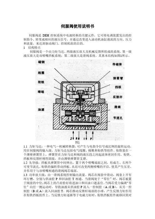
1 结构特点伺服阀是一个由力矩马达、两级液压放大及机械反馈所组成的系统。
第一级液压放大是双喷嘴挡板系统;第二级放大是滑阀系统。
其基本结构如图1所示。
图11.1 力矩马达:一种电气—机械转换器,可产生与电指令信号成比例的旋转运动,用在伺服阀的输入级。
力矩马达包括电气线圈、极靴和衔铁等组件。
衔铁装在一个薄壁弹簧管上,弹簧管在力矩马达和阀的液压段之间起流体密封作用。
衔铁、挡板和反馈杆刚性固接,并由薄壁弹簧管支撑。
1.2 先导级:挡板从弹簧管中间伸出,置于两个喷嘴端面之间,形成左、右两个可变节流孔。
衔铁的偏转带动挡板,从而可改变两侧喷嘴的开启,使其产生压差,并作用于与该喷嘴相通的滑阀阀芯端部。
1.3 功率放大级:由一滑阀系统控制输出流量。
阀芯在阀套中滑动,阀套上开有环行槽,分别与供油腔P和回油腔T相通。
当滑阀处于“零位”时,阀芯被置于阀套的中位;阀芯上的凸肩恰好将进油口和回油口遮盖住。
当阀芯受力偏离“零位”向任一侧运动时,导致油液从供油腔P流入一控制腔(A或B),从另一控制腔(B或A)流入回油腔T。
阀芯推动反馈杆端部的小球,产生反馈力矩作用在衔铁挡板组件上。
当反馈力矩逐渐等于电磁力矩时,衔铁挡板组件被移回到对中的位置。
于是,阀芯停留在某一位置。
在该位置上,反馈力矩等于输入控制电流产生的电磁力矩,因此,阀芯位置与输入控制电流的大小成正比。
1.4 特点:●衔铁及挡板均工作在中立位置附近,线性好●喷嘴挡板级输出驱动力大●阀芯基本处于浮动状态,不易卡住●阀的性能不受伺服阀中间参数的影响,阀的性能稳定,抗干扰能力强,零点漂移小2 工作原理:当力矩马达没有电信号输入时,衔铁位于极靴气隙中间,平衡永久磁铁的磁性力。
当有欲使调节阀动作的电气信号由伺服放大器输入时,力矩马达的线圈中有电流通过,产生一磁场,在磁场作用下,产生偏转力矩,使衔铁旋转,同时带动与之相连的挡板转动,此挡板伸到两个喷嘴中间。
MOOG伺服阀J761-原理……MOOG办事处

MOOG伺服阀J761-003原理……MOOG办事处美国穆格MOOGJ761-003,J761-003系列直动式伺服阀型号:D633,D634系列生产厂家:MOOG 产品说明:高性能直动式伺服阀,由线性力马达直接驱动阀芯运,阀内带有电子放大器对阀芯位置进行闭环控制。
直动式设计避免了先导级的泄漏损失,且动态响应与系统工作压力无关。
安装底面符合ISO4401标准。
频率响应:70HZ阶跃响应:15ms流量控制:3.8-100l/min(1-26gpm)最大工作压力:31.5Mpa该阀适应于金属压制设备,例如剪板机,折弯机,弯管机,木材压机.另外我司优势提供意大利atos阿托斯全系列!备有常规阀现货期待您的来电咨询!!!MOOG伺服阀J761-003原理……MOOG办事处MOOG伺服阀J761-003原理……MOOG办事处格公司(MOOG)是全球电液伺服元件及伺服系统设计及制造领域的领导者,由电液伺服阀的发明者William C. Moog于1951年创立。
产品广泛应用于飞机、卫星、航天飞机、火箭以及各种工业自动化设备。
在工业领域,注塑设备及吹塑设备的伺服控制是我们的重要研究领域之一。
MOOG 是最早进入全电动注塑行业的专业控制厂商之一,向合作伙伴提供DBS、DBM、DS2000 系列驱动器FASTACT 系列电机。
DS2000 驱动器和FAS T 交流伺服电机具有以下一些特点:驱动器可接受三相,50HZ,65到506V间的任意电压;可设定控制交流伺服电机或异步电机;电流环可根据伺服电机特点配置,并按DC BUS变化自动调节,同时提供 B.E.M.F 补偿以及相位自校正功能;速度环内集成了三种数字滤波器,动态性能良好,等等MOOG伺服阀原理J761-003&MOOG办事处MOOG伺服阀J761-003 现货供应!常用系列:D634系列,J761系列,G761系列, D791系列;D792系列,D661系列;D662系列;D663系列;D664系列;D665系列;D633系列等MOOG品牌最早起源于航空航天军事工业领域伺服阀及系统制造,主要经营伺服阀,伺服控制器,电动缸,伺服电机,伺服控制软件,行业应用领域广泛,涉及钢铁冶金,电力电站系统,注塑吹塑成型,材料试验,汽车测试仿真系统,航空测试仿真系统等,MOOG伺服阀J761-003/J761-004稳定可靠全部采用进口低飘移、高稳定度的运算放大器,使控制系统能长期、可靠、稳定地工作。
WE20梳型阀门规格及安装操作说明书
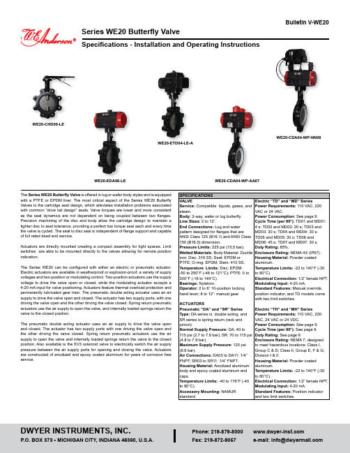
Series WE20 Butterfly ValveSpecifications - Installation and Operating InstructionsBulletin V-WE20The Series WE20 Butterfly Valve is offered in lug or wafer body styles and is equipped with a PTFE or EPDM liner. The most critical aspect of the Series WE20 Butterfly Valves is the cartridge seat design, which alleviates installation problems associated with common “dove tail design” seats. Valve torques are lower and more consistent as the seat dynamics are not dependent on being coupled between two flanges. Precision machining of the disc and body allow the cartridge design to maintain a tighter disc to seat tolerance, providing a perfect low torque seal each and every time the valve is cycled. The seat to disc seal is independent of flange support and capable of full rated dead end service.Actuators are directly mounted creating a compact assembly for tight spaces. Limit switches are able to be mounted directly to the valves allowing for remote position indication.The Series WE20 can be configured with either an electric or pneumatic actuator. Electric actuators are available in weatherproof or explosion-proof, a variety of supply voltages and two-position or modulating control. Two-position actuators use the supply voltage to drive the valve open or closed, while the modulating actuator accepts a 4-20 mA input for valve positioning. Actuators feature thermal overload protection and permanently lubricated gear train. The pneumatic double acting actuator uses an air supply to drive the valve open and closed. The actuator has two supply ports, with one driving the valve open and the other driving the valve closed. Spring return pneumatic actuators use the air supply to open the valve, and internally loaded springs return the valve to the closed position.The pneumatic double acting actuator uses an air supply to drive the valve open and closed. The actuator has two supply ports with one driving the valve open and the other driving the valve closed. Spring return pneumatic actuators use the air supply to open the valve and internally loaded springs return the valve to the closed position. Also available is the SV3 solenoid valve to electrically switch the air supply pressure between the air supply ports for opening and closing the valve. Actuators are constructed of anodized and epoxy coated aluminum for years of corrosion freeservice.WE20-EDA06-LEWE20-CDA04-WP-AA07VALVE DIMENSIONAL DRAWINGWAFER STYLE“WF”LUG STYLE“LT”AUTOMATED VALVE DRAWINGSWafer Valve withPneumatic ActuatorWafer Valve withElectric ActuatorWafer Valve withExplosion-Proof ActuatorLug Valve withPneumatic ActuatorLug Valve withElectric ActuatorLug Valve withExplosion-Proof ActuatorPNEUMATIC ACTUATORNote: For optimal operation, pneumatic actuators should be run with a supply of clean, lubricated air.Spring Return Actuator OperationAir to PORT 2 (the left hand port) causes the actuator to turn counterclockwise (CCW). Loss of air to PORT 2 causes air to exhaust and the actuator turns clockwise (CW). This is the FAIL CLOSE operation.Double Acting Actuators OperationAir to PORT 2 (the left hand port) causes the actuator to turn counterclockwise (CCW). Air to PORT 1 (the right hand port) causes the actuator to turn clockwise (CW).Pneumatic Actuator MaintenanceRoutine maintenance of pneumatic actuator:• Keep the air supply dry and clean• Keep the actuator surface clean and free from dust• Periodic checks should be done to make sure all fittings are tight • P neumatic actuators are supplied with lubrication to last the entire life span ofthe actuator under normal operating conditions. The outer surface of the pneumatic actuator should be clean to avoid friction or corrosion. All fittings and connections should be tight to prevent leaks during operation. Check the bolts mounting the valve to the actuator to make sure they have not come loose during shipping or installation. Make sure the valve and actuator are not rubbing or jamming against other components during operation. The actuator should be inspected annually to make sure all fittings and bolts are tight and nothing has come loose during operation.Disassembling Pneumatic ActuatorsBefore beginning disassembly, ensure that the air supply to the actuator has been disconnected, all accessories have beenremoved, and that the actuator has been disassembled from the valve.1. L oosen the end cap fasteners (23) with a wrench (size varies depending onactuator model). On the spring return actuator, alternate 3 to 5 turns on each fastener until the springs are completely decompressed. Use caution when removing the cap since the springs are under load until the fasteners are fully extended.2. R emove the pinion snap ring (13) with a lock ring tool. The indicator (12) maynow be removed.3. T urn the pinion shaft (2) counter clockwise until the pistons are at the full end oftravel. Disengage the pistons (15) from the pinion. (Note: Low pressure air--3 to 5 psi MAXIMUM--might be required to force the pistons completely from the body.) Note the position of the pistons before removing them from the actuator body. 4. R emove the pinion through the bottom of the actuator. The actuator is nowcompletely disassembled.Be sure the actuator surfaces are free of debris and scratches before reassembling.1. Apply a light film of grease to all O-rings and the pinion before replacing.2. P ut the pinion (2) back through the actuator with the flats of the pinion shaftrunning parallel with the body.3. W hen reassembling the actuator, make sure that the piston racks are square tothe actuator body and returned to their original orientation. (Note: The normal operation of all spring return pneumatic actuators is FAIL CLOSED. To change the orientation to FAIL OPEN, rotate the racks 180º to create a reverse operation.4. W hen replacing springs in a spring return actuator, ensure that the springs arereplaced in their identical position in the end cap from which they were removed. (Note: In some circumstances, you might want to change the standard 80 pound spring set to fit your application and available air pressure.5. Seal the end caps with a petroleum lubricant and bolt to actuator body.6. C heck the seal of the actuator by covering seal areas (pinion, end caps) withsoapy water and using low pressure air to the actuator to ensure that no bubbles are produced.Reassembling Pneumatic ActuatorsWhen working on the Actuator/Valve assembly, disconnect the air or power supply to the actuator. Spring return actuators/valves may change position if power fails or is removed. Never insert any object or body part into the valve body. Severe injury may occur.Pneumatic Actuators Bill of MaterialsELECTRIC ACTUATORSElectric Installation1. Operate valve manually and place in the open position.2. R emove any mechanical stops the valve might have. (DO NOT REMOVE ANYPARTS NECESSARY FOR THE PROPER OPERATION OF THE VALVE, SUCH AS THE PACKING GLAND, PACKING NUT, ETC.)3. E nsure that the actuator output shaft and valve stem are aligned properly. If theyare not, operate the valve manually until they are correct.4. Remove actuator cover.5. B ring power to the actuator. CAUTION: Make sure power is OFF at the mainbox.6. W ire the actuator per the diagram attached to the inside of the cover. Specialactuators (those with positioner boards, etc.) will have diagrams enclosed inside the cover.7. S ecurely tighten bolts used to mount the actuator to a mounting bracket ordirectly to the valve mounting pad if it is ISO5211 compliant.8. C ycle the unit several times and check the open and closed positions of thevalve. Cams are pre-adjusted at the factory; due to the variety of valve designs and types however, slight adjustments might be required.9. Replace cover and tighten screws.To Set The Open Position1. C ycle the valve to the open position by applying power to terminals. The top camand switch control this position. In the open position, the set screw in the top cam will be accessible.2. If the valve is not open completely:A. Slightly loosen the set screw on the top cam.B. R otate the cam clockwise (CW) by hand until the switch makes contact.Contact is made when a slight click can be heard. By making incremental CW movements of the top cam, the valve can be positioned precisely in the desired position.C. When the top cam is set, tighten the set screw securely.3. If the valve opens too far:A. A pply power to terminals. This will begin to rotate valve CW. When valve isfully open and in the exact position desired, remove power from actuator.B. Loosen the set screw in the top cam.C. R otate the top cam counterclockwise (CCW) until the switch arm drops offthe round portion of the cam onto the flat section. A slight click can be heard as the switch changes state.D. Continue applying power to terminals until valve is in the desired position.To Set The Closed Position1. A pply power to terminals to move the valve toward the closed position. Thebottom cam and switch control the closed position. In the closed position, the set screw in the bottom cam will be accessible.2. If the valve is not closed completely:A. Slightly loosen the set screw on the bottom cam.B. R otate the cam counterclockwise (CCW) by hand until the switch makescontact. Contact is made when a slight click can be heard. By making incremental CCW movements of the bottom cam, the valve can be positioned precisely in the desired position.C. When the top cam is set, tighten the set screw securely.3. If the valve closes too far:A. A pply power to terminals. This will begin to rotate valve CCW. When valve isfully closed and in the exact position desired, remove power from actuator.B. Loosen the set screw in the top cam.C. R otate the top cam clockwise (CW) until the switch arm drops off the roundportion of the cam onto the flat section. A slight click can be heard as the switch is no longer making contact with the round part of the cam.D. Continue applying power to terminals until valve is in the desired position.Electric Actuators Wiring Diagram: ACT-TH & ACT-MHWiring Diagrams forTH03-A to TH11-A: 110 VAC, TH03-B to TH11-B: 220 VAC, TH03-C to TH11-C: 24 VACHOTALVE ALVEWiring Diagrams for TH03-D to TH11-D: 24 VDCOPERATION:POWER TO 1 & 2 FOR CCW ROTATION POWER TO 3 & 4 FOR CW ROTATION TERMINALS 5 & 6 FOR FIELD LIGHT INDICATION CONNECTIONSW.#1 SW.#2SWITCH #1 OPEN SWITCH SWITCH #2 CLOSE SWITCHWiring Diagrams forMH03-A to MH11-A: 110 VAC, MH03-B to MH11-B: 220 VAC, MH03-C to MH11-C: 24 VACSW. 1, CLOSESW. 2, OPEN .SW. 3, CLOSE SW. 4, OPEN Wiring Diagrams forMH03-D to MH11-D: 24 VDCSW. 1, CLOSESW. 2, OPEN .SW. 3, CLOSE SW. 4, OPENElectric Actuators Wiring Diagram: ACT-TD & ACT-MDWiring Diagrams forTD02-A to TD07-A: 110 VAC, TD02-B to TD07-B: 220 VAC,TD02-C to TD07-C: 24 VACWiring Diagrams forTD02-D to TD07-D: 24 VDCWiring Diagrams forMD02-A to MD07-A: 110 VAC, MD02-B to MD07-B: 220 VAC,MD02-C to MD07-C: 24 VAC Note: To speed up installation of the control wires to the ACT-MDXX modulating actuator, it is recommended to remove the control module from the actuator. The control module can be removed by removing the two mounting screws on the left and right of the control module. Install the control wires to the correct terminal points and then reinstall the control module.Electric Actuator MaintenanceOnce the actuator has been properly installed, it requires no maintenance. The gear train has been lubricated and in most cases will never be opened.Duty Cycle Definition“Duty Cycle” means the starting frequency.Formula: Running Time ÷ (Running Time + Rest Time) x 100% = duty cycle–> Rest Time = Running Time x (1 - duty cycle) ÷ duty cycleFor example: The running time is 15 seconds30% duty cycle 15 x [(1 - 30%) / 30%] = 35 –> The rest time will be 35 seconds 75% duty cycle 15 x [(1 - 75%) / 75%] = 5 –> The rest time will be 5 seconds If the duty cycle is higher, the rest time will be shortened, which means the starting frequency will be higher.Thermal OverloadAll actuators are equipped with thermal overload protection to guard the motor against damage due to overheating.Mechanical OverloadAll actuators are designed to withstand stall conditions. It is not recommended to subject the unit to repeated stall conditions.Explosion-Proof Electric Actuators1. DO NOT under any circumstances remove the cover of theactuator while in a hazardous location. Removal of the cover while in a hazardous location could cause ignition of hazardous atmospheres.2. D O NOT under any circumstances use an explosion-proof electric actuator in ahazardous location that does not meet the specifications for which the actuator was designed.3. A lways verify that all electrical circuits are de-energized before opening theactuator.4. A lways mount and cycle test the actuator on the valve in a non-hazardouslocation.5. W hen removing the cover, care must be taken not to scratch, scar of deform theflame path of the cover and base of the actuator, since this will negate the NEMA rating of the enclosure.6. W hen replacing the cover, take care that the gasket is in place to assure properclearance after the cover is secured.7. A ll electrical connections must be in accordance with the specifications for whichthe unit is being used.8. S hould the unit ever require maintenance, remove from the hazardous locationbefore attempting to work on the unit. If the actuator is in a critical application, it is advisable to have a standby unit in stock.Electric Actuators Performance RatingMAINTENANCE/REPAIRUpon final installation of the Series WE, only routine maintenance is required. The Series WE is not field serviceable and should be returned if repair is needed. Field repair should not be attempted and may void warranty.WARRANTY/RETURNRefer to “Terms and Conditions of Sale” in our catalog and on our website. Contact customer service to receive a Return Goods Authorization number before shippingthe product back for repair. Be sure to include a brief description of the problem plus any additional application notes.11NOTES____________________________________________________________________________________________________________________________________________________________________________________________________________________________________________________________________________________ __________________________________________________________________________________________________________________________________________ __________________________________________________________________________________________________________________________________________ __________________________________________________________________________________________________________________________________________ __________________________________________________________________________________________________________________________________________ __________________________________________________________________________________________________________________________________________ __________________________________________________________________________________________________________________________________________ __________________________________________________________________________________________________________________________________________ __________________________________________________________________________________________________________________________________________ __________________________________________________________________________________________________________________________________________ __________________________________________________________________________________________________________________________________________ __________________________________________________________________________________________________________________________________________ __________________________________________________________________________________________________________________________________________ __________________________________________________________________________________________________________________________________________ __________________________________________________________________________________________________________________________________________ __________________________________________________________________________________________________________________________________________ __________________________________________________________________________________________________________________________________________ __________________________________________________________________________________________________________________________________________ __________________________________________________________________________________________________________________________________________ __________________________________________________________________________________________________________________________________________ __________________________________________________________________________________________________________________________________________ __________________________________________________________________________________________________________________________________________ __________________________________________________________________________________________________________________________________________ ____________________________________________________________________________________________________________________________________________________________________________________________________________________________________________________________________________________12©Copyright 2022 Dwyer Instruments, Inc.Printed in U.S.A. 7/22FR# 444279-00 Rev. 6。
761系列空气驱动座阀说明书
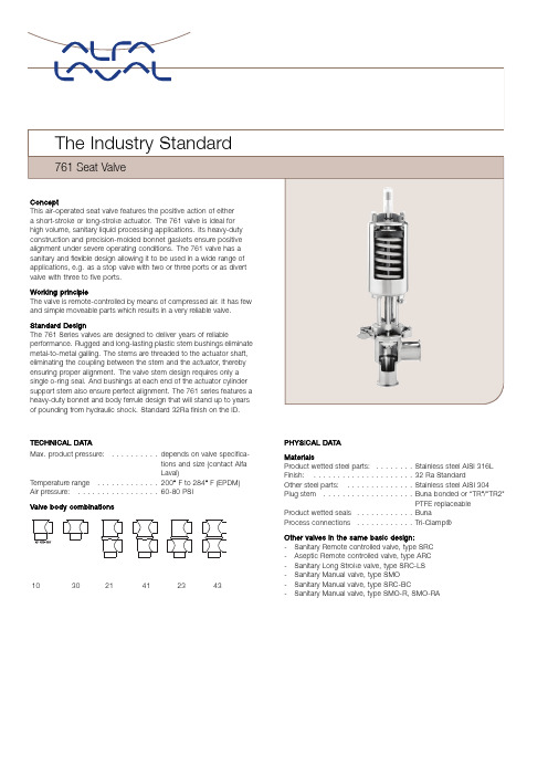
TECHNICAL DATAMax.product pressure:..........depends on valve specifica-tions and size(contact AlfaLaval)Temperature range.............200°F to284°F(EPDM) Air pressure:.................60-80PSIValve bodycombinations103021412343PHYSICAL DATAMaterialsProduct wetted steel parts:........Stainless steel AISI316L Finish:.....................32Ra StandardOther steel parts:..............Stainless steel AISI304 Plug stem...................Buna bonded or“TR”/"TR2"PTFE replaceableProduct wetted seals............BunaProcess connections............Tri-Clamp®Other valves in the same basic design:-Sanitary Remote controlled valve,type SRC-Aseptic Remote controlled valve,type ARC-Sanitary Long Stroke valve,type SRC-LS-Sanitary Manual valve,type SMO-Sanitary Manual valve,type SRC-BC-Sanitary Manual valve,type SMO-R,SMO-RAPressure drop/capacity diagrams761Short-Stroke Divert Valve761Short-Stroke Shut-Off ValveBody Styles21,23,41&43.Body Styles10&30.Flow Pattern:B to A(Solid Curve),B to C(Broken Curve).Flow Pattern:B to A(Solid Curve),A to B(Broken Curve)-Crossbodies In some cases,with low-viscosity liquids,the pressure drop in theOnly.long-stroke valve may actually be greater than the short-stroke valves.In some cases,with low-viscosity liquids,the pressure drop in thelong-stroke valve may actually be greater than the short-stroke valves.761Long-Stroke Divert Valve761Long-Stroke Shut-Off ValvesBody Styles10&30.Body Styles10&30.Flow Pattern:B to A(Solid Curve),B to C(Broken Curve).Flow Pattern:B to A(Solid Curve),A to B(Broken Curve)-CrossbodiesIn some cases,with low viscosity liquids,the pressure drop in theOnlylong-stroke valve may actually be greater than the short-stroke valves.In some cases,with low-viscosity liquids,the pressure drop in thelong-stroke valve may actually be greater than the short-stroke valves.ABCC 76110761-30761-27Reverse-Acting761-47Reverse-ActingBCCCA761-21761-23761-41761-43761Shut-Off and Divert ValvesA BShut-Off Valves Divert&Reverse-Acting*Shut-Off ValvesShort Long Short LongDivert ValvesReverse ActingShut-Off ValvesC Valve Size(Tube OD)inch mm inch mm inch mm inch mm inch mm inch mm inch mm 1-inch14.88378.00NA NA NA NA NA NA NA NA NA NA 2.5064.00 1½-inch17.13435.0021.09536.0020.73526.0024.69627.00 4.63117.007.38187.00 2.7570.00 2-inch17.63448.0021.56548.0021.19538.0025.16639.00 4.13105.007.63194.00 3.5089.00 2½-inch17.56446.0021.53547.0021.85555.0025.81656.00 4.50114.008.00203.00 3.5089.00 3-inch18.06459.0022.03560.0022.85580.0026.81681.00 5.00127.008.75222.00 3.7595.00 4-inch24.97634.0031.09790.0031.00787.0037.09942.00 6.00152.00NA NA 4.00102.00 *Reverse-acting NA in long stroke**For valves with control housings,add the following to dimension A:Short stroke sizes:1-3"(25.4-76.2mm),Add:19/16"(39.7mm)Long stroke sizes:1½-4"(38.1101.6mm),Add:3/4"(19.0mm)761Shut-Off and Divert Valves with Variable and Mid-Position“80S”ActuatorAShut-Off Valves Divert ValvesShort ShortB CValve Size(Tube OD)inch mm inch mm inch mm inch mm 1½-inch17.75451.0023.31592.00 4.62117.00 2.7570.00 2-inch18.25464.0023.56598.00 4.12105.00 3.5089.00 2½-inch18.19462.0023.94608.00 4.50114.00 3.5089.00 3-inch18.69475.0024.69627.00 5.00127.00 3.7595.00761-90“Y”Body Shut-Off ValvesA B CValve Size(Tube OD)inch mm inch mm inch mm 1½-inch20.63524.00 6.38162.0022.31567.002-inch22.38568.007.88200.0024.63625.002½-inch22.94583.009.25235.0025.44646.003-inch28.94735.0010.38264.0029.69754.004-inch32.13816.0012.63321.0032.88835.00*Column“C”represents dimension“A”with the addition of a control housing module.Reverse-Acting Divert Valves761-21MRALL(Left Hand Tangential)761-21MRARR(Right Hand Tangential)A B C D EValve Sizeinch mm inch mm inch mm inch mm inch mm 2-inch 4.72120.00 3.5089.000.5113.0013.69348.00 2½-inch 5.25133.00 6.03153.00 3.5089.000.8121.0013.94354.00 2½HP 5.25133.00 6.03153.00 3.5089.000.8121.0016.28414.00 3HP 5.75146.00 6.28159.00 3.7595.000.8121.0018.88479.00 4HP7.08180.009.30236.00 4.02102.000.4812.0022.00559.00 **For valves with control housings,add the following to dimension E:1½-3"(38-76mm),add19/16"(40mm)Actuator function-Pneumatic downward movement,spring return(NO)-Pneumatic upward movement,spring return(NC)-Pneumatic upward and downward movement(A/A),-Actuator for intermediate position of the valve plug as optionType10(Normally-Open)Shut-off valve holding pressures—70psi air pressure supplied to actuatorShort Stroke Actuator(Standard*)Long Stroke Actuator(Standard*)Type15 Size Elastomer“TR”Stroke Length Elastomer“TR”Stroke Length20PSI 1-inch105psi110psi0.75"NA NA NA50 1½-inch120psi110psi1"120psi110psi2"26 2-inch80psi70psi1"125psi120psi2"18 2½-inch35psi20psi1"60psi50psi2"10 3-inch20psi15psi1"45psi40psi2"7 4-inch35psi20psi2"40psi20psi4"NA*4½"diameter actuator is standard on the1"-3"valves.A6"diameter actuator is supplied with the4"valve.A4½"diameter actuator for the4" valve is available upon request.Type10(Normally-Open)Shut-off valve holding pressures—90psi air pressure supplied to actuatorShort Stroke Actuator(Standard*)Long Stroke Actuator(Standard*) Size Elastomer“TR”Stroke Length Elastomer“TR”Stroke Length 1-inch105psi105psi0.75"NA NA NA 1½-inch150psi150psi1"150psi150psi2"2-inch150psi150psi1"150psi150psi2"2½-inch90psi80psi1"120psi110psi2"3-inch70psi60psi1"80psi70psi2"4-inch80psi75psi2"100psi80psi4"*4½"diameter actuator is standard on the1"-3"valves.A6"diameter actuator is supplied with the4"valve.A4½"diameter actuator for the4" valve is available upon request.Type20(Normally-Closed)Shut-off valve holding pressures(Standard)**Short Stroke Actuator(Standard*)Long Stroke Actuator(Standard*)Type25ReverseActingSize Elastomer“TR”Stroke Length Elastomer“TR”Stroke Length psig 1-inch105psi110psi0.75"NA NA**NA 1½-inch140psi140psi1"140psi140psi2"40 2-inch90psi90psi1"90psi90psi2"25 2½-inch55psi55psi1"55psi55psi2"15 3-inch40psi40psi1"32psi25psi2"10 4-inch65psi65psi2"45psi40psi4"NA*4½"diameter actuator is standard on the1"-3"valves.A6"diameter actuator is supplied with the4"valve.The6"diameter actuator is available, as a heavy duty option,for the3"valve.**On a standard actuator it takes30psi to offset the spring force when fully extended and60psi to fully compress the spring.Type20(Normally-Closed)Optional“HP”high pressure actuator.(6"diameter actuator)Short Stroke Actuator(Standard*)Long Stroke Actuator(Standard*) Size Elastomer“TR”Stroke Length Elastomer“TR”Stroke Length 2½-inch110psi110psi1"115psi110psi2"3-inch95psi90psi1"100psi95psi2"Actuator Air Supply SpecificationsSee chart below for minimum air pressure requirements.Maximum air pressure is100psi(normal).Air volume required is identified by the length of the stroke.Valve Size Stroke(inch)Volume(cu.in.) 1-inch0.7511.101½-3-inch short stroke114.801½-3-inch long stroke229.504-inch short stroke HP250.004-inch long stroke HP495.00Type15diaphragm19.00 Lubricated air is not required.Filtered air and a pressure regulator valve are required.Additional Holding PressureAdditional air supply must be relieved when product pressure is not present.Failure to do so will result in pressure damage to the seat. When using additional air loading it should exceed the minimum required by no more that3to5psig.Example:A customer has an application for a3"valve that is required to hold70psi product pressure with an elastomer(Buna).The valve without an air assist will hold40psi.An additional holding force to overcome30psi(70psi-40psi)is needed.Since the ratio is5:10 (air-to-product pressure ratio)a15psi air assist is needed.Note:Since it takes60psi to fully stroke the valve without air assist,it will take75psi to open the example.(60psi+15psi)Valve SizeAir to ProductPressure RatioMaxRecommendedAir AssistMax.ProductHolding Pressure 1-inch01:10102001½-inch01:1052002-inch02:10101502½-inch03:10201003-inch05:10351004-inch HP04:1025100OptionsEquipment-Process connections,weld,bevel seat-Control and indication(Control Top or ThinkTop®)-High pressure actuator for2½"and3"size-High pressure actuator for2½"and3"size-Three Position Actuator(80)-20Ra or15Ra ID surface finish-Long stroke actuatorMaterial grades-Molded elastomers of EPDM,SFY,or PTFE-O-rings and seals of EPDM or SFY(Flouroelastomer)OrderingPlease state the following when ordering:-Size.-Connections-Valve body combination.-Actuator function,NC,NO or A/A-Options.ESE00511ENUS1505Alfa Laval reserves the right to change specifications without priornotification.ALFA LAVAL is a trademark registered and owned by Alfa LavalCorporate AB.©Alfa LavalHow to contact Alfa LavalContact details for all countriesare continually updated on our website. Please visit toaccess the information direct.。
四向单压入口式控制阀门说明书
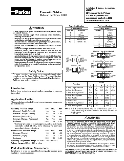
IntroductionFollow these instructions when installing, operating, or servicing the product.Application Limits:These products are intended for use in general purpose compressed air systems only.Operating Pressure Range: kPa PSIG bar Minimum* (Double Solenoid) 138 20 1.38 Minimum* (Single Solenoid) 241 35 2.41 Minimum (Remote Pilot) Vac Vac Vac Minimum (Manual / Mechanical) Vac Vac Vac Maximum 1034 150 10.34 * For lower pressure or vacuum operation, solenoid(s) may beexternally piloted (35 PSIG min.) following the conversion procedure in these instructions.External Pilot Pressure Range: kPa PSIG bar Minimum (Double) 138 20 1.38 Minimum (Single) 241 35 2.41 Maximum 1034 150 10.34 Operating Temperature Range: 0°C to 80°C (32°F to 175°F)Voltage Range: +10% to –15% of ratingPort Identification / Connections:Install valve in circuit per one of the following ANSI diagram (ports marked on valve or subbase):Port #Function1 2 4 3 54-Way, Single Pressure Inlet Cyl.Cyl. Exh. Exh.4-Way, Dual Pressure Exh. Cyl. Cyl. Inlet 1 Inlet 23-Way, Normally Closed Inlet Cyl. — Exh. —3-Way, Normally Open Exh. Cyl. — Inlet —3-Way, Diverter Out 1 Inlet — Out 2 —3-Way, Selector Inlet 1 Out — Inlet 2 —2-Way, Normally Closed Inlet Out — Plug —2-Way, Normally OpenPlugOut—Inlet—NOTE: All 2 & 3-Way functions may use 3-Waybodies (*24** ****).4-Way bodies may be field converted to 2 & 3-Way functions by plugging ports.Installation & Service Instructions V623BP52 Series Air Control Valves ISSUED: September, 2006 Supersedes: September, 2002Doc.# V-623P, ECN# 060870, Rev. 8Pneumatic DivisionRichland, Michigan 490833-Position, 4-Way, All Ports Blocked#12OperatorEnd#14Operator End3-Position, 4-Way, Pressure Center#12Operator End#14Operator End3-Position, 4-Way, Center Exhaust#12Operator End#14Operator End2-Position, 3-Way#10Operator End#12Operator End2-Position, 4-Way#12Operator End#14Operator EndWARNING To avoid unpredictable system behavior that can cause personal injuryand property damage:• Disconnect electrical supply (when necessary) before installation, servicing, or conversion.• Disconnect air supply and depressurize all air lines connected to this product before installation, servicing, or conversion.• Operate within the manufacturer’s specified pressure, temperature, and other conditions listed in these instructions.• Medium must be moisture-free if ambient temperature is below freezing.• Service according to procedures listed in these instructions.• Installation, service, and conversion of these products must be performed by knowledgeable personnel who understand how pneumatic products are to be applied.• After installation, servicing, or conversion, air and electrical supplies (when necessary) should be connected and the product tested for proper function and leakage. If audible leakage is present, or the product does not operate properly, do not put into use.• Warnings and specifications on the product should not be covered by paint, etc. If masking is not possible, contact your local representative for replacement labels.!WARNINGFAILURE OR IMPROPER SELECTION OR IMPROPER USE OF THEPRODUCTS AND/OR SYSTEMS DESCRIBED HEREIN OR RELATED ITEMS CAN CAUSE DEATH, PERSONAL INJURY AND PROPERTY DAMAGE.This document and other information from Parker Hannifin Corporation, its subsidiaries and authorized distributors provide product and/or system options for further investigation by users having technical expertise. It is important that you analyze all aspects of your application, including consequences of any failure and review the information concerning the product or systems in the current product catalog. Due to the variety of operating conditions and applications for these products or systems, the user, through its own analysis and testing, is solely responsible for making the final selection of the products and systems and assuring that all performance, safety and warning requirements of the application are met.The products described herein, including without limitation, product features, specifications, designs, availability and pricing, are subject to change by Parker Hannifin Corporation and its subsidiaries at any time without notice.EXTRA COPIES OF THESE INSTRUCTIONS ARE AVAILABLE FOR INCLUSION IN EQUIPMENT / MAINTENANCE MANUALS THAT UTILIZE THESE PRODUCTS. CONTACT YOUR LOCAL REPRESENTATIVE.!Safety GuideFor more complete information on recommended application guidelines, see the Safety Guide section of Pneumatic Division catalogs or you can download the Pneumatic Division Safety Guide at: /safetyPort Identification 3-Way Service Port No. Function 1 Inlet 2 Cylinder 3 Exhaust 10 Remote Pilot 12 Remote PilotPort Identification4-Way ServicePort No. Function 1 Inlet 2 Cylinder 3 Exhaust 4 Cylinder 5 Exhaust 12 Remote Pilot 14 Remote Pilot52 Series Air Control Valves V-623BPConversion Procedures:Normally Closed 3-Way to Normally Open1. Remove four phillips-head screws from each end section and detach.2. While holding body assembly by the bushings, slide the spool out of the body assembly. Reverse the spool end-for-end and replace it in body assembly.3. Reassemble end sections to opposite ends of body from which they were removed. Tighten screws 1.5 to 2.0 Nm (13 to 18 in-lbs).Internal to External PilotT o operate solenoid valves below their minimum operating pressure, on vacuum, or for dual pressure applications, the valve must be converted to external pilot as follows:1. Remove 1/8" pipe plug and rubber disc from solenoid end(s).2. Remove four phillips-head screws holding solenoid actuating end(s) to body.3. Replace the o-ring with the rubber disc on the exposed end of valve body (disc over thru hole).4. Reassemble solenoid end section(s) to body. Tighten screws 1.5 to 2.0 Nm (13 to 18 in-lbs).5. Attach external pilot supply line(s) (35 PSIG min.) where the 1/8" pipe plug(s) were removed.Service Kits:Valve Seal Kit(Contains all seals found in 3 & 4-Waybodies and all actuator styles) .................................52000 8050 (Fluorocarbon) .........................................................52000 8500Body Service Kit (Contains bushings, springs,retainers and shells for all body styles) ...................52001 8005CAUTION: Foot operated valves must be protected against inadvertent operation that can cause serious bodily injury. Use of a pedal guard is strongly recommended as it will reduce the likelihood of inadvertent operation. If this is not suitable in your application, utilize equivalent protection.Installation & Operating Instructions:Valve should be installed with reasonable accessibility for service whenever possible – repair service kits are available. Keep pipe or tubing lengths to a minimum with inside clean and free of dirt and chips. Pipe joint compound should be used sparingly and applied only to the male pipe, never to the female port. Do not use PTFE tape to seal pipe joints – pieces have a tendency to break off and lodge inside the unit, possibly causing malfunction.Air to the valve must be filtered to realize maximum component life.CAUTION: It is recommended that double solenoid and double remote air pilot operated valves be mounted so that the axis of the valve spool is in the horizontal plane. The valve may be rotated 360° around the axis for mounting convenience.Life Expectancy – Normal multi-million cycle life expectancy of these valves is based on the use of properly filtered air at room temperature.Lubrication – For maximum service life use clean, lubricated air. Valves are shipped pre-lubricated and can be operated without additional lubrication with reduced service life.Recommended Lubricant – Use F442 oil. This oil is specially formulated to provide peak performance and maximum service life from all air operated equipment. Otherwise, use a straight paraffin base mineral oil of viscosity 100-200 SSU @ 100°F and an aniline point greater than 200°F . CAUTION: DO NOT use synthetic, reconstituted, or oils with an alcohol content or detergent additive.CAUTION: This valve shall not be used to actuate a punch press. DO NOT use this valve on punch presses or press brakes. See OSHA 1910.217.Wiring Instructions:Solenoid operators are on the same end as depicted in the ANSI diagrams. Either wire may be “Hot”.NOTE: In addition to above instructions, follow all requirements for localand national electrical codes.Subbase Port Connections:1. Connect inlet air supply to Port 1.2. Connect mufflers (or plumb exhaust) to Ports 3 and 5.3. Connect cylinder Ports 2 and 4 to ends of cylinder or other device to be supplied with air.4. For pilot operated valves connect pilot signal air to Ports 12 and 14.!!!!。
低压铜 钢气气水阀门文档说明书
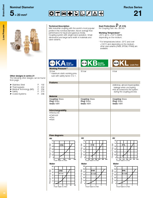
Please consider our security advices on the pages 12/13L o w P r e s s u r eB r a s s /S t e e lL o w P r e s s u r eB r a s s /S t e e lCouplings – with valveSeries 21KAConnectionA HEX mm HEX1 mm L mm L1 mm L2 mm D mmB mm G mm VersionPart NumberPanel Mountwith Plastic Hose Connection4 x 6 mm 141254718163M 10 x 1blank 21KAKS06MPX 4 x 6 mm 141254718163M 10 x 1nickel plated21KAKS06MPN 6 x 8 mm 171754718164M 12 x 1 blank 21KAKS08MPX 6 x 8 mm171754718164M 12 x 1nickel plated21KAKS08MPNPanel Mountfor Plastic Hose Connection for Front Panel Installation4 x 6 mm 222442716245M 20 x 1blank 21KAKE06MPX 4 x 6 mm 222442716245M 20 x 1nickel plated21KAKE06MPN 6 x 8 mm 222442716245M 20 x 1blank 21KAKE08MPX 6 x 8 mm222442716245M 20 x 1nickel plated21KAKE08MPNPanel Mount for Hose Barbfor Front Panel Installation4 mm 2224461716245M 20 x 1blank 21KATE04MPX 4 mm 2224461716245M 20 x 1nickel plated21KATE04MPN 6 mm 2224461716245M 20 x 1blank 21KATE06MPX 6 mm 2224461716245M 20 x 1nickel plated21KATE06MPN 8 mm 2224461716245M 20 x 1blank 21KATE08MPX 8 mm 2224461716245M 20 x 1nickel plated21KATE08MPN 9 mm2224461716245M 20 x 1blank 21KATE09MPX 9 mm 2224461716245M 20 x 1nickel plated21KATE09MPN 10 mm 2224461716245M 20 x 1blank 21KATE10MPX 10 mm 2224461716245M 20 x 1nickel plated21KATE10MPN Panel Mount with Hose Barb4 mm 1212601714164M 10 x 1blank 21KATS04MPX 4 mm 1212601714164M 10 x 1nickel plated21KATS04MPN 5 mm 1717601714164M 12 x 1 blank 21KATS05MPX 5 mm 1717601714164M 12 x 1 nickel plated21KATS05MPN 6 mm 1717601714164M 12 x 1 blank 21KATS06MPX 6 mm 1717601714164M 12 x 1 nickel plated21KATS06MPN 8 mm 1717601714164M 12 x 1 blank 21KATS08MPX 8 mm1717601714164M 12 x 1 nickel plated21KATS08MPN 9 mm 1719601714164M 14 x 1blank 21KATS09MPX 9 mm 1719601714164M 14 x 1nickel plated21KATS09MPN 10 mm 1719601714164M 14 x 1blank 21KATS10MPX 10 mm 1719601714164M 14 x 1nickel plated21KATS10MPN Plastic Hose Connection with Spring Guard4 x 6 mm 141257616M 10 x 1blank 21KAKK06MPX 4 x 6 mm 141257616M 10 x 1nickel plated21KAKK06MPN 6 x 8 mm 141307616M 10 x 1blank 21KAKK08MPX 6 x 8 mm141307616M 10 x 1nickel plated21KAKK08MPNL o w P r e s s u r eB r a s s /S t e e lPlease consider our security advices on the pages 12/13L o w P r e s s u r eB r a s s /S t e e lPlease consider our security advices on the pages 12/13L o w P r e s s u r eB r a s s /S t e e lCouplings – with valveSeries 21KBConnectionA HEX mm HEX1 mm L mm L1 mm L2 mm D mmB mm G mm VersionPart NumberPanel Mountwith Plastic Hose Connection4 x 6 mm 141454718164M 10 x 1blank 21KBKS06MPX 4 x 6 mm 141454718164M 10 x 1nickel plated21KBKS06MPN 6 x 8 mm 171754718164M 12 x 1blank 21KBKS08MPX 6 x 8 mm171754718164M 12 x 1nickel plated21KBKS08MPNPanel Mountfor Plastic Hose Connection for Front Panel Installation4 x 6 mm 222442716245M 20 x 1blank 21KBKE06MPX 4 x 6 mm 222442716245M 20 x 1nickel plated21KBKE06MPN 6 x 8 mm 222442716245M 20 x 1blank 21KBKE08MPX 6 x 8 mm222442716245M 20 x 1nickel plated21KBKE08MPNPanel Mount for Hose Barbfor Front Panel Installation4 mm 2224461716245M 20 x 1blank 21KBTE04MPX 4 mm 2224461716245M 20 x 1nickel plated21KBTE04MPN 6 mm 2224461716245M 20 x 1blank 21KBTE06MPX 6 mm 2224461716245M 20 x 1nickel plated21KBTE06MPN 9 mm2224461716245M 20 x 1blank 21KBTE09MPX 9 mm 2224461716245M 20 x 1nickel plated21KBTE09MPN 10 mm 2224461716245M 20 x 1blank 21KBTE10MPX 10 mm 2224461716245M 20 x 1nickel plated21KBTE10MPN Panel Mount with Hose Barb4 mm 1414601714164M 10 x 1blank 21KBTS04MPX 4 mm 1414601714164M 10 x 1nickel plated21KBTS04MPN 5 mm 1717601714164M 12 x 1blank 21KBTS05MPX 5 mm 1717601714164M 12 x 1nickel plated21KBTS05MPN 6 mm 1717601714164M 12 x 1blank 21KBTS06MPX 6 mm 1717601714164M 12 x 1nickel plated21KBTS06MPN 8 mm1717601714164M 12 x 1blank 21KBTS08MPX 8 mm 1717601714164M 12 x 1nickel plated21KBTS08MPN 9 mm 1719601714164M 12 x 1blank 21KBTS09MPX 9 mm 1719601714164M 12 x 1nickel plated21KBTS09MPN Plastic Hose Connection with Spring Guard4 x 6 mm 141257616M 10 x 1blank 21KBKK06MPX 4 x 6 mm 141257616M 10 x 1nickel plated21KBKK06MPN 6 x 8 mm 141307616M 10 x 1blank 21KBKK08MPX 6 x 8 mm141307616M 10 x 1nickel plated21KBKK08MPNL o w P r e s s u r eB r a s s /S t e e lPlease consider our security advices on the pages 12/13L o w P r e s s u r eB r a s s /S t e e lPlease consider our security advices on the pages 12/134041L o w P r e s s u r eB r a s s /S t e e lPlease consider our security advices on the pages 12/13Please consider our security advices on the pages 12/13L o w P r e s s u r e S t a i n l e s s S t e e l193194195L o w P r e s s u r eS t a i n l e s s S t e e lPlease consider our security advices on the pages 12/13196L o w P r e s s u r eS t a i n l e s s S t e e lCouplings – with valveSeries 21KBConnectionA HEX mm HEX1 mm L mm L1 mm L2 mmD mm B mmG mmVersionPart NumberMale ThreadG 1/81436716AISI 30321KBAW10RVX G 1/81436716AISI 316 L 21KBAW10EVX G 1/41738916AISI 30321KBAW13RVX G 1/41738916AISI 316 L 21KBAW13EVX G 3/81938916AISI 30321KBAW17RVX G 3/81938916AISI 316 L 21KBAW17EVX Female ThreadG 1/81436916AISI 30321KBIW10RVX G 1/81436916AISI 316 L 21KBIW10EVX G 1/41738716AISI 30321KBIW13RVX G 1/41738716AISI 316 L 21KBIW13EVX G 3/81938916AISI 30321KBIW17RVX G 3/81938916AISI 316 L 21KBIW17EVX Hose Barb4 mm 14461716AISI 30321KBTF04RVX 4 mm 14461716AISI 316 L 21KBTF04EVX5 mm 14461716AISI 30321KBTF05RVX6 mm 14461716AISI 30321KBTF06RVX 6 mm 14461716AISI 316 L 21KBTF06EVX 8 mm 14461716AISI 30321KBTF08RVX 8 mm 14461716AISI 316 L 21KBTF08EVX 9 mm14461716AISI 30321KBTF09RVX 9 mm 14461716AISI 316 L 21KBTF09EVX 10 mm 14461716AISI 30321KBTF10RVX 10 mm 14461716AISI 316 L 21KBTF10EVX 6 mm Parker14502016AISI 30321KBTP06RVXwith Plastic Hose Connection4 x 6 mm 14427616M 10 x 1AISI 30321KBKO06RVX 4 x 6 mm 14427616M 10 x 1AISI 316 L 21KBKO06EVX 6 x 8 mm 14427616M 12 x 1AISI 30321KBKO08RVX 6 x 8 mm14427616M 12 x 1AISI 316 L21KBKO08EVXPanel Mountwith Plastic Hose Connection4 x 6 mm 141454718164M 10 x 1AISI 30321KBKS06RVX 4 x 6 mm 141454718164M 10 x 1AISI 316 L 21KBKS06EVX 6 x 8 mm171454718164M 12 x 1AISI 30321KBKS08RVXPanel Mount with Hose Barb8 mm1717601714164M 12 x 1AISI 30321KBTS08RVX197L o w P r e s s u r eS t a i n l e s s S t e e lPlease consider our security advices on the pages 12/13198199L o w P r e s s u r eS t a i n l e s s S t e e lPlease consider our security advices on the pages 12/13。
五大类阀门使用说明书
D3/6/971J (X)蝶阀使用说明书标准文档标准文档D3/6/971J (X)对夹式蝶阀使用说明书该系列蝶阀为软密封对夹式,驱动装置通过阀轴带动阀板作0-90 ゜范围旋转,作起闭和调节动作。
1.压力级: 1.0MPa ,1.6 MPa;2.使用温度: -15 ℃---75 ℃;3.适用介质:水、蒸汽、天然气、食品、药品、油类。
一、结构特点:1、结构简单紧凑, 90 ゜范围内旋转起闭迅速、准确;2、操作扭矩小,省力轻巧;3、双向密封、泄漏量为零。
二、安装使用注意事项:1、该系列蝶阀可以安装在任意位置的管道上,客户根据自动控制系统的要求,结合驱动装置进行安装,安装位置应保证使用、维修方便;2、该系列蝶阀可双向使用无需考虑介质流向;3、存放应保持干燥,阀板处于微闭状态(约3 ~5 °;)4、安装前应清理阀门内腔,不允许有污物附着。
5、驱动装置具体安装、使用、贮存、保管等注意事项,按相关要求执行。
三、常见故障及排除方法:常见故障产生原因排除方法1 、管道内有杂物; 1 、清除杂物关闭不严2 、管道法兰选用错误,安装有错位 2 、选用蝶式专用法兰标准文档1 、驱动装置与阀轴之间的连接平键损坏;1 、更换连接平键;无法开起2 、阀轴与阀板连接锥销断裂或脱落2 、更换连接锥销标准文档Z41H闸阀使用说明书标准文档标准文档Z41H闸阀使用说明书Z41H 闸阀为阀板在阀杆的带动下,沿阀座密封面作升降运动而达到启闭的目的。
1 、压力级: 1.0MPa, 1.6MPa, 2.5 MPa, 4.0MPa,6.4 MPa,10 MPa;2 、使用温度: -29 ℃---425 ℃3、使用介质:水、蒸汽、油品等非腐蚀性介质。
一、结构特点1、阀体通道为全通径,流体阻力小。
2、介质可从闸阀二侧任意方向流过,不受介质流动方向的限制。
3、全开对密封面受冲蚀性较小,密封性能好。
二、维护保养1、运输途中的维护阀门在运输途中应注意要轻装轻卸,以防止法兰密封面磕碰损坏,应将密封面擦干净后再关闭。
- 1、下载文档前请自行甄别文档内容的完整性,平台不提供额外的编辑、内容补充、找答案等附加服务。
- 2、"仅部分预览"的文档,不可在线预览部分如存在完整性等问题,可反馈申请退款(可完整预览的文档不适用该条件!)。
- 3、如文档侵犯您的权益,请联系客服反馈,我们会尽快为您处理(人工客服工作时间:9:00-18:30)。
J761Y-200、250 H61Y -200、250 型高加配套入口阀、出口阀
使用说明书
杭州华惠阀门有限公司
杭州阀门厂、杭州电站阀门厂
一九九九年
目录
一、主要用途与性能
二、结构简述
三、主要技术特性
四、主要外型和连接尺寸
五、主要零件材料
六、使用与安装说明
该系列阀门严禁解体!
一、主要用途与性能
J761Y-200、250型(DN175,DN225,DN300)入口阀和H61Y -200、250 型(DN175,DN225,DN300)出口阀(止回阀)是分别装在5万、10万与20万机组高压加热器给水管道的入口与出口处,当高压加热器管系破裂,引起水位升高,达到报警水位时,快速启闭阀打开,使入口阀迅速关闭,同时也使止回阀迅速关闭,切断高压加热器给水,使高压加热器解列,锅炉给水则通过旁路进入省煤器,从而起到保护高压加热器的作用,使机组正常运行。
高压加热器给水保护系统简图参见图三。
二、结构简述
1、入口阀(见图一)入口阀阀体呈直通式,外置活塞式结构和手轮强制关闭系统。
给水从阀座上方一侧引入,从另一侧进入高压加热器,阀上方有两个旁路弯道与止回阀旁路弯道相连接。
阀门有上下两个密封面,高压加热器正常运行时,入口阀开启,阀瓣上浮,与上密封面接触,当高压加热器发生故障时,凝结水则通过快速启闭阀进入活塞上方,使阀瓣下落,关闭阀门。
给水通过两旁路管道直接进入锅炉省煤器,而不经过高压加热器,使高压加热器解列。
入口阀主要由阀体、支架、阀瓣、阀杆、活塞、手轮关闭装置等组成。
阀体有上下两个阀座,下阀座焊在阀体上,上阀座由阀盖通过内套压紧。
阀瓣上下两个密封面均采用硬质合金堆焊而成,阀杆表面经氮化处理,抗擦伤、耐腐蚀。
活塞缸为焊接件,缸体内表面经Ni 基合金镀层处理,有良好的防腐及耐磨性。
活塞由“ O“型环密封,支架起支撑活塞缸及连接阀体的作用。
手轮关闭系统中装有推力球轴承和钢球,使关闭时省力方便。
上部有一螺孔和一焊接法兰,前者为凝结水进口,后者为排除凝结水出口。
阀体下部进出口侧各有一个管接头来连接向高压加热器内注水的管道。
2、止回阀(见图二)止回阀与入口阀一样,阀体呈直通式,有三个进口,一个出口,上部有两个旁路进口与入口阀旁路管相连,下部一端与高压加热器出口相连,另一端为出口,该出口支管与锅炉给水管道相连。
止回阀主要由阀体、阀盖、支架、阀瓣、阀杆等组成。
阀体中镶焊阀座,阀座和阀瓣密封面采用硬质合金堆焊而成,阀杆表面经氮化处理,具有良好的抗擦伤性和耐腐蚀性。
手轮其作用是当高压加热器解列,给水旁路供给锅炉时下阀口应关闭,若阀瓣不下来时需转动手轮,使阀杆向下运动,顶下阀瓣把阀门关闭。
三、主要技术特性
四、主要外形及连接尺寸
五、主要零件材料
六、使用与安装说明
1、入口阀与止回阀必须垂直安装,阀门与管道焊好后,应清洗干净,清除焊渣与污物。
2、冷凝水通道应为不锈钢材质,在进口处装设过滤网或过滤器。
3、投入使用时,入口阀与止回阀的手轮均应将阀杆旋到最高位置。
4、启动运行的一般步骤如下:
1) 启动时,先操作两阀上的手轮,使阀杆升起,仅留1~2 个丝扣;
2) 开启活塞上下的放气、放水阀,此时缸内有一股来自节流孔板(孔径
一般为φ1.5mm左右)的细流通过。
3) 开启注水阀往管系中注水,当管系内的压力接近或达到给水压力
时,由于面积差而使作用在阀瓣上下的力不同,使阀瓣开启,与上阀座接触并密封,关闭给水通往旁路的通道。
4) 给水通过入口阀进入高加管系内,流经各台高加管系以后流向出口
阀进入省煤器。
5) 高加水侧投入后,关闭注水阀和活塞上的放气阀
6) 缓开抽汽阀投运汽侧,高压加热器投入正常运行。