微技术 Microtech
微机电系统技术及应用

微机电系统技术及应用微机电系统技术(Micro-Electro-Mechanical Systems,MEMS)是指一种集成微型机械、电子和计算机技术的系统,它利用微型加工技术将传感器、执行器和电子元器件等多种功能集成到一个芯片上,从而实现在微小空间内进行感测、信号处理和控制的复杂系统。
自20世纪80年代以来,MEMS技术在各个领域得到了广泛的应用,成为现代科技进步的重要方向之一。
一、MEMS技术的基本原理MEMS技术的实现基于微机械制造技术,即利用光刻、蚀刻、离子注入、薄膜沉积、微调工艺等多种微加工技术,在硅基底板上制造出微型机械和微型电子元器件,将它们集成在一起实现控制系统的复杂功能。
常见的MEMS元件包括传感器和执行器两类。
传感器一般是将物理量转换成电信号输出的元件,MEMS传感器主要有压力传感器、加速度传感器、角速度传感器、温度传感器、化学传感器等,它们的结构和工作原理各不相同。
以加速度传感器为例,它主要是通过微型悬臂等结构感受加速度的作用,在振动部件上加上感应电极,利用柔性连接器将机械运动转化成电信号输出。
执行器是将电信号转换成物理运动的设备,MEMS执行器主要有微型电机、微泵、微阀门和微喷头等。
以微型电机为例,它主要包括固定部件和旋转部件,其结构具有一定的复杂性。
电机的旋转部件通常采用转子-定子结构,采用MEMS技术可以制造出特殊形状的转子并将其悬挂在薄膜支撑结构上,转子与定子之间通过电容传感器实现控制,电容传感器输出的信号被用于控制电机的转速和方向。
二、MEMS技术的应用领域MEMS技术的应用范围非常广泛,包括空间、军事、医疗、汽车、电子信息等多个领域,在以下几个方面得到了广泛应用。
1.传感器MEMS传感器可以感测体积小、重量轻、功耗低、响应速度快、精度高等诸多优点,使之成为传感器领域的重要技术。
它广泛应用于汽车行业、工业自动化控制、医疗设备等领域,如安全气囊用于汽车碰撞检测、指纹识别传感器、手机加速度传感器等。
微芯片技术(Microchip Technology)无传感器场向控制(FOC)技术指南说明书
Microchip Technology Inc.User GuideSensor less Field Oriented Control with SAM E54Contents1. Introduction (2)1.1. SAME54 Microcontroller Card for ATBLDC24V Motor Control Starter Kit (2)1.2. ATBLDC24V-STK Features (3)1.3. Microchip ATSAME54 MOTOR MCU Board (4)1.3.1. MCU Card (4)1.3.2. Power Supply (4)1.3.3. Embedded Debugger (4)1.3.4. 67-pin MCU-DRIVER Board Interface (5)1.4. Motor Specification (6)2. Software Requirement (7)3. Getting Started with ATBLDC24V-STK (7)4. Firmware User Configuration (11)5. Software Implementation (12)6. References (14)7. Revision History (14)1.Introduction1.1.S AME54 Microcontroller Card for ATBLDC24V Motor Control Starter KitThe ATSAME54MOTOR is a MCU card for Atmel® Motor control low voltage starter kits. The hardware has the ARM® M4 core -based SAME54 MCU, with integrated on-board debug support. The MCU card can be directly used with the currently available ATSAMD21BLDC24V-STK®, a low voltage BLDC, PMSM motor control starter kit. The kit contains a driver board hardware with half-bridge power MOSFET drivers, current and voltage sensing circuit, Hall, and Encoder interface, fault protection circuits, etc. Supported by the Atmel studio integrated development platform, the kit provides easy access to the features of SAME54 MCU and explains how to integrate the device in a custom motor control application.Figure 1 Atmel low voltage motor control kit1.2.A TBLDC24V-STK FeaturesATBLDC24V-STK has the following features:• Pluggable MCU card interface• Debug support using on-board Atmel EDBG device• Three half-bridge MOSFET driver• Motor BEMF sensing• Motor individual phase current sensing• DC-bus voltage sensing• Hall sensor interface• Encoder s ensor interface• Over-current protection support• Over-voltage protection at 30VDC• 5V and 3.3V MCU card support• Selectable MCU supply voltage• Reverse power supply voltage protection• Atmel Xplained Pro compatible header interface• On board Temperature sensor• On board serial flash• LED fault indications• Atmel studio plug-and-use support using unique ID device1.3.M icrochip ATSAME54 MOTOR MCU Board1.3.1.MCU CardSAM E54 is a high-performance Flash microcontroller (MCU) based on the 32-bit ARM® Cortex®-M4 RISC (403 CoreMark at 120MHz) processor with floating point unit (FPU). The device operates at a maximum speed of 120 MHz, features up to 1024 Kbytes of Flash, up to 4 Kbytes of TCM (Tightly Coupled Memory)and up to 256 Kbytes of SRAM.The device is intended to work with external 12MHz oscillator. An external reset switch is connected to the MCU RESET pin.Figure 2 ATSAME54 MCU Card1.3.2.Power SupplyThe ATSAME54 MOTOR MCU card takes 3.3VDC supply from the 67-pin edge connector. Both the EDBG device and the Main MCU operate from 3.3VDC. The power supply selection jumper on the Driver board should be connected to 3V3 selection..1.3.3.Embedded DebuggerThe ATSAME54 MCU is interfaced to the EDBG debug device. The EDBG uses SWD interface for programming and debugging the main MCU. A debug header is also provided on the MCU board with ARM Cortex® debug pin out. An external debugger can be connected to this debug port.The DGI is a proprietary communication interface used by the Atmel Data Visualizer software to communicate with the development kits through the EDBG. ATSAME54 connected to the EDBG device, with DGI SPI interface and uses the Atmel ADP protocol.High Speed USB port of the EDBG is accessible at the driver board. EDBG USB enumerates as a composite device supporting debug, DGI SPI, and CDC interfaces.The USB port of the EDBG is connected to the Micro-USB connecter on the driver board.1.3.4.67-pin MCU-DRIVER Board InterfaceATSAME54 MCU card is connected to driver board through 67-pin interface as shown below.Figure 3 67 Pin MCU-Driver Board Interface1.4.M otor Specification2.Software RequirementTo run this demo below mentioned software should be installed on the PC.3.Getting Started with ATBLDC24V-STKThis chapter is a step-by-step guide to get started with the ATSAME54 for ATBLDC24V-STK.1.ATBLDC24V-STK kit contains a fully assembled chassis and 24VDC power adaptor.2.Make sure switch SW1 on driver board (ATBLDC24V) is set to USB/X5V.3.Make sure jumper (J26) on driver board (ATBLDC24V) is set to 3.3V.4.Connect the power adaptor to the “SUPPLY-IN connector”. Connect white color cable to + PIN.Figure 4 Kit with Power and USB Ports Connected5.Connect the Micro-USB cable to the “EDBG-USB connector” and PC USB port.6.Switch ON the power adaptor.7.The power LED indications on the MCU card are now ON.8. If MCU is pre-programmed then directly open "Data Visualizer". If it’s not, then program itthrough Atmel studio and run the program first and then open the data visualizer9.In the "Data Visualizer Connect Window" select the kit from the DGI control panel's drop downlist.Figure 5 Data Visualizer Connect Window10.Click "Connect".11.The Data Visualizer default window will pop up once the connection is made. All the fields shallshow default values as shown below.Figure 6 Data Visualizer Start Window12.Click on "START/STOP" button to turn the motor ON with default values.Figure 7 Data Visualizer Motor Start Window13.One can adjust the graph by selecting checkbox "Automatically fit Y" for better visualization.14.To change the parameter, enter the value in a input field and press "Enter". For example, tochange the motor speed, type in the desired speed within the Reference Speed (RPM) input box and press "Enter".Figure 8 Data Visualizer Change Parameter Online15.To stop the motor, click on the “Stop" button. It will ramp down and stop the motor.Figure 9 Data visualizer Stop motor window4.Firmware User ConfigurationAlgorithm can be fine-tuned for any motor by updating motor parameters in “userparams.h” file. Following are the configurations available for the user to modify the motor and algorithm parameters.5.Software ImplementationPWM event generation unit is configured to trigger AFEC module to start adc conversion. Once the trigger is received by AFEC module, two configured phase current measurements are simultaneously sampled and conversion takes place. Phase current result ready event will generate interrupt. Then DC bus voltage is measured inside interrupt. In addition, speed POT is measured if it is enabled.The FOC algorithm is executed inside ADC end of conversion interrupt handler. This interrupt is dedicated for fast controlling and it’s in sync with PWM. If any fast controlling tasks need to be added then this is the place. Apart from this, slow control loop is also available and its frequency can be configured by “SLOW_LOOP_TIME_SEC” in user configurations. Slow loop execution frequency should be in multiple of PWM frequency. Speed ramp and speed PI control loop is executed from slow control loop. If any additional tasks one has to execute at slower rate, then “SlowControlLoop()” function is a place holder.ADCEOCInterruptHandlerRead 2 phase currents Software trigger for DC bus and POTmeasurementClarke Transform Convert balanced three-phase quantities to balanced two-phase quadrature quantitiesPark TransformTwo-phase orthogonal stationary system to orthogonal rotating reference framePLL EstimatorBEMF based PLL observer to Estimate Motor Position and SpeedPI ControllersId(Flux), Iq (Torque) PI controllersInverse Park Transform Rotating reference frame to Orthogonal stationary reference frame Inverse Clarke Transform2 axis orthogonal frame to3 phase stationary frameSVPWMSpace vector modulation to update PWM duty cycleSTOP SlowControlLoopSpeedRamp()PI ControlSpeed PI controlSTOPFigure 10 Control loop flow chart6.ReferencesApp Note - /downloads/en/AppNotes/00002520B.pdfAtmel Studio 7 - /microsite/atmel-studio/Data Visualizer - https:///Products/Details/0b2891f4-167a-49fc-b3f0-b882c7a11f98 7.Revision History。
微系统技术介绍

2
1 What Is MICROSYSTEMS
微系统是以微电子技术、射频与无线电技术、光学(或光电子学) 技术、微机电系统(MEMS)等技术为核心,从系统工程的高度出 发,通过封封、互连等精细加工技术,在框架、基板等载体上制 造、装配、集成微小型化功能装置。
我们所讨论的微系统大量应用于信息工程领域,因此微系统也可 以称为信息工程微系统。
4、什么是微电子封装(Microelectronic Packaging)
5、微电子封装发展进程(Development)
6、微系统封装技术的地位和作用(Role)
7、微系统封装中的技术挑战(The Challenge)
4/13/2020
13
2 微系统相关技术基础
Microsystems Products And Related Technologies Relations
4/13/2020
7
1 What Is MICROSYSTEMS
微系统与集成电路制造的关系(Cont.)
• 因此,微系统的整个制造过程,即芯片加工、集成组装、封装测试等要 比集成电路制造过程复杂得多。
• 微系统技术的发展已经使许多高速信息处理、大容量存储、超低功耗的 电子产品成为现实,未来的微系统产品将覆盖人类生活的方方面面。
4/13/2020
8
1 What Is MICROSYSTEMS
Typical 微系统产品
Smart Watches
4/13/2020
9
1 What Is MICROSYSTEMS
Typical 微系统产品
Multimedia Personal
Communication Terminal
美国微技术MICROTECH

美国微技术MICROTECH概述本文章来源:主题名品网|高端名刀。
美国微技术MICROTECH是高级刀具技术的家园,成立于1994年,1998年和1999年Microtech被刀锋杂志评选为生产质量奖,2000年凭Lightfoot LCC获得年度合作奖。
除了标准产品,也接单为客户定制刀具。
使用了计算机控制的机床减少误差,手柄使用6061-T6铝合金材料并且经过阳极电镀,刀刃是采用美国产的154CM钢材。
Microtech在材料和工艺方面终身保用,提供表面修复和零件替换服务。
美国微技术Socom Selta Tanto品牌MICROTECH 美国微技术型号Socom Selta Tanto刀刃材质S35VN刀具全长22.9CM刃长9.8CM刃厚0.39CM刃宽 2.8CM硬度58-60HRC柄材6AL-4V 钛合金产地美国附件Maxpedition刀套美国微技术Socom Selta Tanto品牌MICROTECH 美国微技术型号Socom Selta Tanto刀刃材质大马士革刀具全长22.9CM刃长9.8CM刃厚0.39CM刃宽 2.8CM硬度60-62HRC柄材6AL-4V 钛合金产地美国附件Maxpedition刀套美国微技术Crosshair 101-1BL品牌MICROTECH 美国微技术型号101-1BL刀刃材质D-2刀具全长26.1CM刃长11.6CM刃厚0.54CM刃宽 4.3CM硬度59-61HRC柄材Tan polymer(硝聚合物)产地美国附件Kydex刀鞘美国微技术143-2TC品牌MICROTECH 美国微技术型号143-2TC刀刃材质S35VN刀具全长24.1CM刃长9.2CM刃厚0.3CM刃宽 2.0CM硬度58-60HRC柄材6061-T6铝合金产地美国附件尼龙刀套美国微技术144-2TC品牌MICROTECH 美国微技术型号144-2TC COMBAT TROODON T/E 刀刃材质S35-VN刀具全长24.3CM刃长9.6CM刃厚0.31CM刃宽 2.15CM硬度58-60HRC柄材6061-T6铝合金产地美国附件尼龙刀套美国微技术144-2GC品牌MICROTECH 美国微技术型号144-2GC COMBAT TROODON T/E 刀刃材质S35-VN刀具全长24.3CM刃长9.6CM刃厚0.31CM刃宽 2.15CM硬度58-60HRC柄材6061-T6铝合金产地美国附件尼龙刀套。
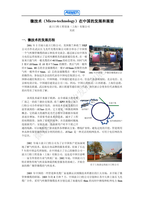
微技术(Micro-technology)在中国的发展和展望
北京联通五环线项目
回顾波立门特公司的成长经历,每一个足迹都有波立门特 人“与客户建立强大和长久的关系,以信任为基础,以服务为 保证,以不断创新为目标,用高质量的产品来满足我们的客户” 的宗旨烙印。我们的客户、我们的伙伴关系、我们的产品品质、 我们全球一体化的气吹技术和我们的服务使我们度过了通信工 程市场最低迷的几年。今天,波立门特公司已经成为了气吹敷 缆设备、气吹系统配套产品和专用工具的最大供应商,并且一 直保持其气吹设备和技术的领先者地位。
该项技术最早来源于欧洲,由全球最大的光缆
厂商之一的荷兰德拉克集团、荷兰 KPN 和瑞士波立
接入
门特公司合作研制开发的。该项技术也就是我们目
长途干线
前常谈到的—JETnet 技术。它主要是一种新的网络 光纤到户
概念,它的最大优越性是光纤芯数可以根据市场需
求逐步增加,不需要考虑未来的需求,减少了工程 的初期投资,加快了投资回报率,并具能随时随地
HDPE 硅芯管
商不是厂家,对厂家信誉的负责全在于个人的修养。厂家和代理
商之间的关系缺乏约束,因而许多代理商的行为全部取决于市场
的发展,今天他可能代理一家的产品,但明天也许由于市场问题
和受利润最大化的驱动,他可能会去代理其他厂家的产品甚至是
竞争对手的产品。现在有些客户询问其他厂家的气吹机是否也可
以升级为微管气吹机,我认为能否升级为微管气吹机,全在于厂 家是否在研发和升级他的产品,如果厂家要保证其产品一直处于
长度(M)
2. 1 家台湾光缆厂做了特种光纤在 1.6mm 的不锈钢钢管内的气吹试验。 3. 浙江大学 863 国家科研项目做过特殊条件下的微缆气吹试
验和报告以及海底气吹试验。
与此同时波立门特公司还和国内的 7 家光缆厂合作,将微 技术推广到了南通电信、杭州电力、福建移动、十堰电信、上 海电信、北京联通、中石化仪征-长岭的长途干线线、中石化北 京六环线等通信工程项目并且和 1 家台湾本土的光缆厂家合作 使气吹光纤束(EPFU)进入了台湾中华电信的电信大楼。在微 技术的推广过程中,波立门特公司还和北京、上海、广东、河 北、中石油、中石化、总参等通信部门的设计院进行过气吹微 管微缆的技术交流。并且和许多光缆厂、管道厂以及网络工程 公司一起为客户举办了 10 余次的气吹演示,为中石化 1000 公 里的长途干线提供了为期 4 天的微管微缆的施工技术培训。
什么是微米技术50字作文

什么是微米技术50字作文英文回答:Microtechnology, also known as micromachining or micromanufacturing, is a technology that involves the fabrication of structures and devices at the micron scale. It enables the production of miniaturized components and systems with high precision and accuracy.One example of microtechnology is the microelectromechanical systems (MEMS), which are tiny devices that combine mechanical and electrical components. MEMS can be found in various applications such as sensors, actuators, and microphones. For instance, the accelerometer in our smartphones that detects motion and orientation is a MEMS device.Another example is the microfluidic devices, which manipulate and control small amounts of fluids. These devices are used in medical diagnostics, drug deliverysystems, and lab-on-a-chip technologies. For example, microfluidic chips can be used to analyze blood samples for diseases or to perform DNA sequencing.Microtechnology has revolutionized many industries and has a wide range of applications. It has enabled the development of smaller and more efficient electronic devices, medical implants, and sensors. It has also opened up new possibilities in fields such as aerospace, automotive, and telecommunications.中文回答:微米技术,也被称为微加工或微制造,是一种在微米尺度上制造结构和设备的技术。
微芯片技术(Microchip Technology) VSC8504-01数据手册说明书

VSC8504-01 Datasheet Quad-Port 10/100/1000BASE-T PHY with SynchronousEthernet and QSGMII/SGMII MACMicrosemi HeadquartersOne Enterprise, Aliso Viejo,CA 92656 USAWithin the USA: +1 (800) 713-4113 Outside the USA: +1 (949) 380-6100 Sales: +1 (949) 380-6136Fax: +1 (949) 215-4996Email: *************************** ©2018 Microsemi, a wholly owned subsidiary of Microchip Technology Inc. All rights reserved. Microsemi and the Microsemi logo are registered trademarks of Microsemi Corporation. All other trademarks and service marks are the property of their respective owners. Microsemi makes no warranty, representation, or guarantee regarding the information contained herein or the suitability of its products and services for any particular purpose, nor does Microsemi assume any liability whatsoever arising out of the application or use of any product or circuit. The products sold hereunder and any other products sold by Microsemi have been subject to limited testing and should not be used in conjunction with mission-critical equipment or applications. Any performance specifications are believed to be reliable but are not verified, and Buyer must conduct and complete all performance and other testing of the products, alone and together with, or installed in, any end-products. Buyer shall not rely on any data and performance specifications or parameters provided by Microsemi. It is the Buyer’s responsibility to independently determine suitability of any products and to test and verify the same. The information provided by Microsemi hereunder is provided “as is, where is” and with all faults, and the entire risk associated with such information is entirely with the Buyer. Microsemi does not grant, explicitly or implicitly, to any party any patent rights, licenses, or any other IP rights, whether with regard to such information itself or anything described by such information. Information provided in this document is proprietary to Microsemi, and Microsemi reserves the right to make any changes to the information in this document or to any products and services at any time without notice.About MicrosemiMicrosemi, a wholly owned subsidiary of Microchip Technology Inc. (Nasdaq: MCHP), offers a comprehensive portfolio of semiconductor and system solutions for aerospace & defense, communications, data center and industrial markets. Products include high-performance and radiation-hardened analog mixed-signal integrated circuits, FPGAs, SoCs and ASICs; power management products; timing and synchronization devices and precise time solutions, setting the world's standard for time; voice processing devices; RF solutions; discrete components; enterprise storage and communication solutions, security technologies and scalable anti-tamper products; Ethernet solutions; Power-over-Ethernet ICs andmidspans; as well as custom design capabilities and services. Learn more at .Contents1Revision History . . . . . . . . . . . . . . . . . . . . . . . . . . . . . . . . . . . . . . . . . . . . . . . . . . . . .11.1Revision4.3 . . . . . . . . . . . . . . . . . . . . . . . . . . . . . . . . . . . . . . . . . . . . . . . . . . . . . . . . . . . . . . . . . . . . . . . 11.2Revision4.2 . . . . . . . . . . . . . . . . . . . . . . . . . . . . . . . . . . . . . . . . . . . . . . . . . . . . . . . . . . . . . . . . . . . . . . . 11.3Revision 4.1 . . . . . . . . . . . . . . . . . . . . . . . . . . . . . . . . . . . . . . . . . . . . . . . . . . . . . . . . . . . . . . . . . . . . . . . 11.4Revision 4.0 . . . . . . . . . . . . . . . . . . . . . . . . . . . . . . . . . . . . . . . . . . . . . . . . . . . . . . . . . . . . . . . . . . . . . . . 11.5Revision2.0 . . . . . . . . . . . . . . . . . . . . . . . . . . . . . . . . . . . . . . . . . . . . . . . . . . . . . . . . . . . . . . . . . . . . . . . 12Product Overview . . . . . . . . . . . . . . . . . . . . . . . . . . . . . . . . . . . . . . . . . . . . . . . . . . .22.1Key Features . . . . . . . . . . . . . . . . . . . . . . . . . . . . . . . . . . . . . . . . . . . . . . . . . . . . . . . . . . . . . . . . . . . . . . 32.1.1Low Power . . . . . . . . . . . . . . . . . . . . . . . . . . . . . . . . . . . . . . . . . . . . . . . . . . . . . . . . . . . . . . . . . 32.1.2Advanced Carrier Ethernet Support . . . . . . . . . . . . . . . . . . . . . . . . . . . . . . . . . . . . . . . . . . . . . 32.1.3Wide Range of Support . . . . . . . . . . . . . . . . . . . . . . . . . . . . . . . . . . . . . . . . . . . . . . . . . . . . . . . 32.1.4Flexibility . . . . . . . . . . . . . . . . . . . . . . . . . . . . . . . . . . . . . . . . . . . . . . . . . . . . . . . . . . . . . . . . . . 32.2Block Diagram . . . . . . . . . . . . . . . . . . . . . . . . . . . . . . . . . . . . . . . . . . . . . . . . . . . . . . . . . . . . . . . . . . . . . 43Functional Descriptions . . . . . . . . . . . . . . . . . . . . . . . . . . . . . . . . . . . . . . . . . . . . . . .53.1Operating Modes . . . . . . . . . . . . . . . . . . . . . . . . . . . . . . . . . . . . . . . . . . . . . . . . . . . . . . . . . . . . . . . . . . . 53.1.1QSGMII/SGMII MAC-to-1000BASE-X Link Partner . . . . . . . . . . . . . . . . . . . . . . . . . . . . . . . . . 53.1.2QSGMII/SGMII MAC-to-100BASE-FX Link Partner . . . . . . . . . . . . . . . . . . . . . . . . . . . . . . . . . 73.1.3QSGMII/SGMII MAC-to-AMS and 1000BASE-X Media SerDes . . . . . . . . . . . . . . . . . . . . . . . . 73.1.4QSGMII/SGMII MAC-to-AMS and 100BASE-FX Media SerDes . . . . . . . . . . . . . . . . . . . . . . . . 83.1.5QSGMII/SGMII MAC-to-AMS and Protocol Transfer Mode . . . . . . . . . . . . . . . . . . . . . . . . . . . . 93.1.6QSGMII/SGMII MAC-to-Cat5 Link Partner . . . . . . . . . . . . . . . . . . . . . . . . . . . . . . . . . . . . . . . 103.1.7QSGMII/SGMII MAC-to-Protocol Transfer Mode . . . . . . . . . . . . . . . . . . . . . . . . . . . . . . . . . . . 103.1.81000BASE-X MAC-to-Cat5 Link Partner . . . . . . . . . . . . . . . . . . . . . . . . . . . . . . . . . . . . . . . . . 113.2SerDes MAC Interface . . . . . . . . . . . . . . . . . . . . . . . . . . . . . . . . . . . . . . . . . . . . . . . . . . . . . . . . . . . . . . 113.2.1SerDes MAC . . . . . . . . . . . . . . . . . . . . . . . . . . . . . . . . . . . . . . . . . . . . . . . . . . . . . . . . . . . . . . 123.2.2SGMII MAC . . . . . . . . . . . . . . . . . . . . . . . . . . . . . . . . . . . . . . . . . . . . . . . . . . . . . . . . . . . . . . . 123.2.3QSGMII MAC . . . . . . . . . . . . . . . . . . . . . . . . . . . . . . . . . . . . . . . . . . . . . . . . . . . . . . . . . . . . . . 123.3SerDes Media Interface . . . . . . . . . . . . . . . . . . . . . . . . . . . . . . . . . . . . . . . . . . . . . . . . . . . . . . . . . . . . . 133.3.1QSGMII/SGMII to 1000BASE-X . . . . . . . . . . . . . . . . . . . . . . . . . . . . . . . . . . . . . . . . . . . . . . . 133.3.2QSGMII/SGMII to 100BASE-FX . . . . . . . . . . . . . . . . . . . . . . . . . . . . . . . . . . . . . . . . . . . . . . . 133.3.3QSGMII to SGMII Protocol Conversion . . . . . . . . . . . . . . . . . . . . . . . . . . . . . . . . . . . . . . . . . . 143.3.4Unidirectional Transport for Fiber Media . . . . . . . . . . . . . . . . . . . . . . . . . . . . . . . . . . . . . . . . . 143.4PHY Addressing and Port Mapping . . . . . . . . . . . . . . . . . . . . . . . . . . . . . . . . . . . . . . . . . . . . . . . . . . . . 143.4.1PHY Addressing . . . . . . . . . . . . . . . . . . . . . . . . . . . . . . . . . . . . . . . . . . . . . . . . . . . . . . . . . . . 143.4.2SerDes Port Mapping . . . . . . . . . . . . . . . . . . . . . . . . . . . . . . . . . . . . . . . . . . . . . . . . . . . . . . . 143.5Cat5 Twisted Pair Media Interface . . . . . . . . . . . . . . . . . . . . . . . . . . . . . . . . . . . . . . . . . . . . . . . . . . . . . 143.5.1Voltage Mode Line Driver . . . . . . . . . . . . . . . . . . . . . . . . . . . . . . . . . . . . . . . . . . . . . . . . . . . . 153.5.2Cat5 Autonegotiation and Parallel Detection . . . . . . . . . . . . . . . . . . . . . . . . . . . . . . . . . . . . . . 153.5.3Automatic Crossover and Polarity Detection . . . . . . . . . . . . . . . . . . . . . . . . . . . . . . . . . . . . . . 153.5.4Manual HP Auto-MDIX Setting . . . . . . . . . . . . . . . . . . . . . . . . . . . . . . . . . . . . . . . . . . . . . . . . 163.5.5Link Speed Downshift . . . . . . . . . . . . . . . . . . . . . . . . . . . . . . . . . . . . . . . . . . . . . . . . . . . . . . . 163.5.6Energy Efficient Ethernet . . . . . . . . . . . . . . . . . . . . . . . . . . . . . . . . . . . . . . . . . . . . . . . . . . . . . 163.5.7Ring Resiliency . . . . . . . . . . . . . . . . . . . . . . . . . . . . . . . . . . . . . . . . . . . . . . . . . . . . . . . . . . . . 173.6Automatic Media Sense Interface Mode . . . . . . . . . . . . . . . . . . . . . . . . . . . . . . . . . . . . . . . . . . . . . . . . 173.7Reference Clock . . . . . . . . . . . . . . . . . . . . . . . . . . . . . . . . . . . . . . . . . . . . . . . . . . . . . . . . . . . . . . . . . . 183.7.1Configuring the Reference Clock . . . . . . . . . . . . . . . . . . . . . . . . . . . . . . . . . . . . . . . . . . . . . . . 183.7.2Single-Ended REFCLK Input . . . . . . . . . . . . . . . . . . . . . . . . . . . . . . . . . . . . . . . . . . . . . . . . . . 183.7.3Differential REFCLK Input . . . . . . . . . . . . . . . . . . . . . . . . . . . . . . . . . . . . . . . . . . . . . . . . . . . . 193.8Ethernet Inline Powered Devices . . . . . . . . . . . . . . . . . . . . . . . . . . . . . . . . . . . . . . . . . . . . . . . . . . . . . . 193.9IEEE 802.3af PoE Support . . . . . . . . . . . . . . . . . . . . . . . . . . . . . . . . . . . . . . . . . . . . . . . . . . . . . . . . . . 213.10ActiPHY Power Management . . . . . . . . . . . . . . . . . . . . . . . . . . . . . . . . . . . . . . . . . . . . . . . . . . . . . . . . 213.10.1Low Power State . . . . . . . . . . . . . . . . . . . . . . . . . . . . . . . . . . . . . . . . . . . . . . . . . . . . . . . . . . . 223.10.2Link Partner Wake-Up State . . . . . . . . . . . . . . . . . . . . . . . . . . . . . . . . . . . . . . . . . . . . . . . . . . 223.10.3Normal Operating State . . . . . . . . . . . . . . . . . . . . . . . . . . . . . . . . . . . . . . . . . . . . . . . . . . . . . . 223.11Media Recovered Clock Outputs . . . . . . . . . . . . . . . . . . . . . . . . . . . . . . . . . . . . . . . . . . . . . . . . . . . . . . 223.11.1Clock Selection Settings . . . . . . . . . . . . . . . . . . . . . . . . . . . . . . . . . . . . . . . . . . . . . . . . . . . . . 223.11.2Clock Output Squelch . . . . . . . . . . . . . . . . . . . . . . . . . . . . . . . . . . . . . . . . . . . . . . . . . . . . . . . 233.12Serial Management Interface . . . . . . . . . . . . . . . . . . . . . . . . . . . . . . . . . . . . . . . . . . . . . . . . . . . . . . . . . 233.12.1SMI Frames . . . . . . . . . . . . . . . . . . . . . . . . . . . . . . . . . . . . . . . . . . . . . . . . . . . . . . . . . . . . . . . 233.12.2SMI Interrupt . . . . . . . . . . . . . . . . . . . . . . . . . . . . . . . . . . . . . . . . . . . . . . . . . . . . . . . . . . . . . . 243.13LED Interface . . . . . . . . . . . . . . . . . . . . . . . . . . . . . . . . . . . . . . . . . . . . . . . . . . . . . . . . . . . . . . . . . . . . . 253.13.1LED Modes . . . . . . . . . . . . . . . . . . . . . . . . . . . . . . . . . . . . . . . . . . . . . . . . . . . . . . . . . . . . . . . 253.13.2Extended LED Modes . . . . . . . . . . . . . . . . . . . . . . . . . . . . . . . . . . . . . . . . . . . . . . . . . . . . . . . 273.13.3LED Behavior . . . . . . . . . . . . . . . . . . . . . . . . . . . . . . . . . . . . . . . . . . . . . . . . . . . . . . . . . . . . . 273.13.4Basic Serial LED Mode . . . . . . . . . . . . . . . . . . . . . . . . . . . . . . . . . . . . . . . . . . . . . . . . . . . . . . 283.13.5Enhanced Serial LED Mode . . . . . . . . . . . . . . . . . . . . . . . . . . . . . . . . . . . . . . . . . . . . . . . . . . 283.13.6LED Port Swapping . . . . . . . . . . . . . . . . . . . . . . . . . . . . . . . . . . . . . . . . . . . . . . . . . . . . . . . . . 293.14Fast Link Failure Indication . . . . . . . . . . . . . . . . . . . . . . . . . . . . . . . . . . . . . . . . . . . . . . . . . . . . . . . . . . 293.15Integrated Two-Wire Serial Multiplexer . . . . . . . . . . . . . . . . . . . . . . . . . . . . . . . . . . . . . . . . . . . . . . . . . 293.15.1Read/Write Access Using the Two-Wire Serial MUX . . . . . . . . . . . . . . . . . . . . . . . . . . . . . . . 303.16GPIO Pins . . . . . . . . . . . . . . . . . . . . . . . . . . . . . . . . . . . . . . . . . . . . . . . . . . . . . . . . . . . . . . . . . . . . . . . 313.17Testing Features . . . . . . . . . . . . . . . . . . . . . . . . . . . . . . . . . . . . . . . . . . . . . . . . . . . . . . . . . . . . . . . . . . 313.17.1Ethernet Packet Generator . . . . . . . . . . . . . . . . . . . . . . . . . . . . . . . . . . . . . . . . . . . . . . . . . . . 313.17.2CRC Counters . . . . . . . . . . . . . . . . . . . . . . . . . . . . . . . . . . . . . . . . . . . . . . . . . . . . . . . . . . . . . 323.17.3Far-End Loopback . . . . . . . . . . . . . . . . . . . . . . . . . . . . . . . . . . . . . . . . . . . . . . . . . . . . . . . . . . 323.17.4Near-End Loopback . . . . . . . . . . . . . . . . . . . . . . . . . . . . . . . . . . . . . . . . . . . . . . . . . . . . . . . . . 323.17.5Connector Loopback . . . . . . . . . . . . . . . . . . . . . . . . . . . . . . . . . . . . . . . . . . . . . . . . . . . . . . . . 333.17.6SerDes Loopbacks . . . . . . . . . . . . . . . . . . . . . . . . . . . . . . . . . . . . . . . . . . . . . . . . . . . . . . . . . 333.17.7VeriPHY Cable Diagnostics . . . . . . . . . . . . . . . . . . . . . . . . . . . . . . . . . . . . . . . . . . . . . . . . . . . 373.17.8JTAG Boundary Scan . . . . . . . . . . . . . . . . . . . . . . . . . . . . . . . . . . . . . . . . . . . . . . . . . . . . . . . 373.17.9JTAG Instruction Codes . . . . . . . . . . . . . . . . . . . . . . . . . . . . . . . . . . . . . . . . . . . . . . . . . . . . . 383.17.10Boundary Scan Register Cell Order . . . . . . . . . . . . . . . . . . . . . . . . . . . . . . . . . . . . . . . . . . . . 403.18100BASE-FX Halt Code Transmission and Reception . . . . . . . . . . . . . . . . . . . . . . . . . . . . . . . . . . . . . 403.19Configuration . . . . . . . . . . . . . . . . . . . . . . . . . . . . . . . . . . . . . . . . . . . . . . . . . . . . . . . . . . . . . . . . . . . . . 413.19.1Initialization . . . . . . . . . . . . . . . . . . . . . . . . . . . . . . . . . . . . . . . . . . . . . . . . . . . . . . . . . . . . . . . 424Registers . . . . . . . . . . . . . . . . . . . . . . . . . . . . . . . . . . . . . . . . . . . . . . . . . . . . . . . . .434.1Register and Bit Conventions . . . . . . . . . . . . . . . . . . . . . . . . . . . . . . . . . . . . . . . . . . . . . . . . . . . . . . . . 434.2IEEE802.3 and Main Registers . . . . . . . . . . . . . . . . . . . . . . . . . . . . . . . . . . . . . . . . . . . . . . . . . . . . . . . 444.2.1Mode Control . . . . . . . . . . . . . . . . . . . . . . . . . . . . . . . . . . . . . . . . . . . . . . . . . . . . . . . . . . . . . . 454.2.2Mode Status . . . . . . . . . . . . . . . . . . . . . . . . . . . . . . . . . . . . . . . . . . . . . . . . . . . . . . . . . . . . . . 464.2.3Device Identification . . . . . . . . . . . . . . . . . . . . . . . . . . . . . . . . . . . . . . . . . . . . . . . . . . . . . . . . 474.2.4Autonegotiation Advertisement . . . . . . . . . . . . . . . . . . . . . . . . . . . . . . . . . . . . . . . . . . . . . . . . 474.2.5Link Partner Autonegotiation Capability . . . . . . . . . . . . . . . . . . . . . . . . . . . . . . . . . . . . . . . . . 484.2.6Autonegotiation Expansion . . . . . . . . . . . . . . . . . . . . . . . . . . . . . . . . . . . . . . . . . . . . . . . . . . . 484.2.7Transmit Autonegotiation Next Page . . . . . . . . . . . . . . . . . . . . . . . . . . . . . . . . . . . . . . . . . . . . 494.2.8Autonegotiation Link Partner Next Page Receive . . . . . . . . . . . . . . . . . . . . . . . . . . . . . . . . . . 494.2.91000BASE-T Control . . . . . . . . . . . . . . . . . . . . . . . . . . . . . . . . . . . . . . . . . . . . . . . . . . . . . . . . 494.2.101000BASE-T Status . . . . . . . . . . . . . . . . . . . . . . . . . . . . . . . . . . . . . . . . . . . . . . . . . . . . . . . . 504.2.11MMD Access Control Register . . . . . . . . . . . . . . . . . . . . . . . . . . . . . . . . . . . . . . . . . . . . . . . . 514.2.12MMD Address or Data Register . . . . . . . . . . . . . . . . . . . . . . . . . . . . . . . . . . . . . . . . . . . . . . . . 514.2.131000BASE-T Status Extension 1 . . . . . . . . . . . . . . . . . . . . . . . . . . . . . . . . . . . . . . . . . . . . . . . 514.2.14100BASE-TX/FX Status Extension . . . . . . . . . . . . . . . . . . . . . . . . . . . . . . . . . . . . . . . . . . . . . 514.2.151000BASE-T Status Extension 2 . . . . . . . . . . . . . . . . . . . . . . . . . . . . . . . . . . . . . . . . . . . . . . . 524.2.16Bypass Control . . . . . . . . . . . . . . . . . . . . . . . . . . . . . . . . . . . . . . . . . . . . . . . . . . . . . . . . . . . . 534.2.18Error Counter 2 . . . . . . . . . . . . . . . . . . . . . . . . . . . . . . . . . . . . . . . . . . . . . . . . . . . . . . . . . . . . 544.2.19Error Counter 3 . . . . . . . . . . . . . . . . . . . . . . . . . . . . . . . . . . . . . . . . . . . . . . . . . . . . . . . . . . . . 544.2.20Extended Control and Status . . . . . . . . . . . . . . . . . . . . . . . . . . . . . . . . . . . . . . . . . . . . . . . . . . 544.2.21Extended PHY Control Set 1 . . . . . . . . . . . . . . . . . . . . . . . . . . . . . . . . . . . . . . . . . . . . . . . . . . 554.2.22Extended PHY Control Set 2 . . . . . . . . . . . . . . . . . . . . . . . . . . . . . . . . . . . . . . . . . . . . . . . . . . 564.2.23Interrupt Mask . . . . . . . . . . . . . . . . . . . . . . . . . . . . . . . . . . . . . . . . . . . . . . . . . . . . . . . . . . . . . 574.2.24Interrupt Status . . . . . . . . . . . . . . . . . . . . . . . . . . . . . . . . . . . . . . . . . . . . . . . . . . . . . . . . . . . . 584.2.25Device Auxiliary Control and Status . . . . . . . . . . . . . . . . . . . . . . . . . . . . . . . . . . . . . . . . . . . . 584.2.26LED Mode Select . . . . . . . . . . . . . . . . . . . . . . . . . . . . . . . . . . . . . . . . . . . . . . . . . . . . . . . . . . . 594.2.27LED Behavior . . . . . . . . . . . . . . . . . . . . . . . . . . . . . . . . . . . . . . . . . . . . . . . . . . . . . . . . . . . . . 604.2.28Extended Page Access . . . . . . . . . . . . . . . . . . . . . . . . . . . . . . . . . . . . . . . . . . . . . . . . . . . . . . 61 4.3Extended Page 1 Registers . . . . . . . . . . . . . . . . . . . . . . . . . . . . . . . . . . . . . . . . . . . . . . . . . . . . . . . . . . 614.3.1SerDes Media Control . . . . . . . . . . . . . . . . . . . . . . . . . . . . . . . . . . . . . . . . . . . . . . . . . . . . . . . 624.3.2Cu Media CRC Good Counter . . . . . . . . . . . . . . . . . . . . . . . . . . . . . . . . . . . . . . . . . . . . . . . . . 624.3.3Extended Mode Control . . . . . . . . . . . . . . . . . . . . . . . . . . . . . . . . . . . . . . . . . . . . . . . . . . . . . . 634.3.4ActiPHY Control . . . . . . . . . . . . . . . . . . . . . . . . . . . . . . . . . . . . . . . . . . . . . . . . . . . . . . . . . . . . 634.3.5PoE and Miscellaneous Functionality . . . . . . . . . . . . . . . . . . . . . . . . . . . . . . . . . . . . . . . . . . . 654.3.6Ethernet Packet Generator Control 1 . . . . . . . . . . . . . . . . . . . . . . . . . . . . . . . . . . . . . . . . . . . 654.3.7Ethernet Packet Generator Control 2 . . . . . . . . . . . . . . . . . . . . . . . . . . . . . . . . . . . . . . . . . . . 66 4.4Extended Page 2 Registers . . . . . . . . . . . . . . . . . . . . . . . . . . . . . . . . . . . . . . . . . . . . . . . . . . . . . . . . . . 664.4.1Cu PMD Transmit Control . . . . . . . . . . . . . . . . . . . . . . . . . . . . . . . . . . . . . . . . . . . . . . . . . . . . 664.4.2EEE Control . . . . . . . . . . . . . . . . . . . . . . . . . . . . . . . . . . . . . . . . . . . . . . . . . . . . . . . . . . . . . . . 684.4.3Ring Resiliency Control . . . . . . . . . . . . . . . . . . . . . . . . . . . . . . . . . . . . . . . . . . . . . . . . . . . . . . 69 4.5Extended Page 3 Registers . . . . . . . . . . . . . . . . . . . . . . . . . . . . . . . . . . . . . . . . . . . . . . . . . . . . . . . . . . 704.5.1MAC SerDes PCS Control . . . . . . . . . . . . . . . . . . . . . . . . . . . . . . . . . . . . . . . . . . . . . . . . . . . . 704.5.2MAC SerDes PCS Status . . . . . . . . . . . . . . . . . . . . . . . . . . . . . . . . . . . . . . . . . . . . . . . . . . . . 714.5.3MAC SerDes Clause 37 Advertised Ability . . . . . . . . . . . . . . . . . . . . . . . . . . . . . . . . . . . . . . . 724.5.4MAC SerDes Clause 37 Link Partner Ability . . . . . . . . . . . . . . . . . . . . . . . . . . . . . . . . . . . . . . 724.5.5MAC SerDes Status . . . . . . . . . . . . . . . . . . . . . . . . . . . . . . . . . . . . . . . . . . . . . . . . . . . . . . . . 724.5.6Media SerDes Transmit Good Packet Counter . . . . . . . . . . . . . . . . . . . . . . . . . . . . . . . . . . . . 734.5.7Media SerDes Transmit CRC Error Counter . . . . . . . . . . . . . . . . . . . . . . . . . . . . . . . . . . . . . . 734.5.8Media SerDes PCS Control . . . . . . . . . . . . . . . . . . . . . . . . . . . . . . . . . . . . . . . . . . . . . . . . . . . 734.5.9Media SerDes PCS Status . . . . . . . . . . . . . . . . . . . . . . . . . . . . . . . . . . . . . . . . . . . . . . . . . . . 744.5.10Media SerDes Clause 37 Advertised Ability . . . . . . . . . . . . . . . . . . . . . . . . . . . . . . . . . . . . . . 744.5.11Media SerDes Clause 37 Link Partner Ability . . . . . . . . . . . . . . . . . . . . . . . . . . . . . . . . . . . . . 744.5.12Media SerDes Status . . . . . . . . . . . . . . . . . . . . . . . . . . . . . . . . . . . . . . . . . . . . . . . . . . . . . . . . 754.5.13Fiber Media CRC Good Counter . . . . . . . . . . . . . . . . . . . . . . . . . . . . . . . . . . . . . . . . . . . . . . . 754.5.14Fiber Media CRC Error Counter . . . . . . . . . . . . . . . . . . . . . . . . . . . . . . . . . . . . . . . . . . . . . . . 75 4.6General Purpose Registers . . . . . . . . . . . . . . . . . . . . . . . . . . . . . . . . . . . . . . . . . . . . . . . . . . . . . . . . . . 754.6.1Reserved General Purpose Address Space . . . . . . . . . . . . . . . . . . . . . . . . . . . . . . . . . . . . . . 764.6.2SIGDET/GPIO Control . . . . . . . . . . . . . . . . . . . . . . . . . . . . . . . . . . . . . . . . . . . . . . . . . . . . . . . 764.6.3GPIO Control 2 . . . . . . . . . . . . . . . . . . . . . . . . . . . . . . . . . . . . . . . . . . . . . . . . . . . . . . . . . . . . 774.6.4GPIO Input . . . . . . . . . . . . . . . . . . . . . . . . . . . . . . . . . . . . . . . . . . . . . . . . . . . . . . . . . . . . . . . . 784.6.5GPIO Output . . . . . . . . . . . . . . . . . . . . . . . . . . . . . . . . . . . . . . . . . . . . . . . . . . . . . . . . . . . . . . 794.6.6GPIO Pin Configuration . . . . . . . . . . . . . . . . . . . . . . . . . . . . . . . . . . . . . . . . . . . . . . . . . . . . . . 794.6.7Microprocessor Command . . . . . . . . . . . . . . . . . . . . . . . . . . . . . . . . . . . . . . . . . . . . . . . . . . . 804.6.8MAC Configuration and Fast Link . . . . . . . . . . . . . . . . . . . . . . . . . . . . . . . . . . . . . . . . . . . . . . 804.6.9Two-Wire Serial MUX Control 1 . . . . . . . . . . . . . . . . . . . . . . . . . . . . . . . . . . . . . . . . . . . . . . . 814.6.10Two-Wire Serial MUX Control 2 . . . . . . . . . . . . . . . . . . . . . . . . . . . . . . . . . . . . . . . . . . . . . . . 814.6.11Two-Wire Serial MUX Data Read/Write . . . . . . . . . . . . . . . . . . . . . . . . . . . . . . . . . . . . . . . . . . 824.6.12Recovered Clock 1 Control . . . . . . . . . . . . . . . . . . . . . . . . . . . . . . . . . . . . . . . . . . . . . . . . . . . 824.6.13Recovered Clock 2 Control . . . . . . . . . . . . . . . . . . . . . . . . . . . . . . . . . . . . . . . . . . . . . . . . . . . 834.6.14Enhanced LED Control . . . . . . . . . . . . . . . . . . . . . . . . . . . . . . . . . . . . . . . . . . . . . . . . . . . . . . 844.6.15Global Interrupt Status . . . . . . . . . . . . . . . . . . . . . . . . . . . . . . . . . . . . . . . . . . . . . . . . . . . . . . . 85 4.7Clause 45 Registers to Support Energy Efficient Ethernet and 802.3bf . . . . . . . . . . . . . . . . . . . . . . . . 864.7.1PCS Status 1 . . . . . . . . . . . . . . . . . . . . . . . . . . . . . . . . . . . . . . . . . . . . . . . . . . . . . . . . . . . . . . 864.7.2EEE Capability . . . . . . . . . . . . . . . . . . . . . . . . . . . . . . . . . . . . . . . . . . . . . . . . . . . . . . . . . . . . . 874.7.4EEE Advertisement . . . . . . . . . . . . . . . . . . . . . . . . . . . . . . . . . . . . . . . . . . . . . . . . . . . . . . . . . 874.7.5EEE Link Partner Advertisement . . . . . . . . . . . . . . . . . . . . . . . . . . . . . . . . . . . . . . . . . . . . . . . 875Electrical Specifications . . . . . . . . . . . . . . . . . . . . . . . . . . . . . . . . . . . . . . . . . . . . . .895.1DC Characteristics . . . . . . . . . . . . . . . . . . . . . . . . . . . . . . . . . . . . . . . . . . . . . . . . . . . . . . . . . . . . . . . . . 895.1.1VDD25 . . . . . . . . . . . . . . . . . . . . . . . . . . . . . . . . . . . . . . . . . . . . . . . . . . . . . . . . . . . . . . . . . . . 895.1.2LED and GPIO . . . . . . . . . . . . . . . . . . . . . . . . . . . . . . . . . . . . . . . . . . . . . . . . . . . . . . . . . . . . . 895.1.3Internal Pull-Up or Pull-Down Resistors . . . . . . . . . . . . . . . . . . . . . . . . . . . . . . . . . . . . . . . . . 895.1.4Reference Clock . . . . . . . . . . . . . . . . . . . . . . . . . . . . . . . . . . . . . . . . . . . . . . . . . . . . . . . . . . . 905.1.5SerDes Interface (SGMII) . . . . . . . . . . . . . . . . . . . . . . . . . . . . . . . . . . . . . . . . . . . . . . . . . . . . 905.1.6Enhanced SerDes Interface (QSGMII) . . . . . . . . . . . . . . . . . . . . . . . . . . . . . . . . . . . . . . . . . . 925.1.7Current Consumption . . . . . . . . . . . . . . . . . . . . . . . . . . . . . . . . . . . . . . . . . . . . . . . . . . . . . . . 935.1.8Thermal Diode . . . . . . . . . . . . . . . . . . . . . . . . . . . . . . . . . . . . . . . . . . . . . . . . . . . . . . . . . . . . . 945.2AC Characteristics . . . . . . . . . . . . . . . . . . . . . . . . . . . . . . . . . . . . . . . . . . . . . . . . . . . . . . . . . . . . . . . . . 945.2.1Reference Clock . . . . . . . . . . . . . . . . . . . . . . . . . . . . . . . . . . . . . . . . . . . . . . . . . . . . . . . . . . . 945.2.2Recovered Clock . . . . . . . . . . . . . . . . . . . . . . . . . . . . . . . . . . . . . . . . . . . . . . . . . . . . . . . . . . . 955.2.3SerDes Outputs . . . . . . . . . . . . . . . . . . . . . . . . . . . . . . . . . . . . . . . . . . . . . . . . . . . . . . . . . . . . 965.2.4SerDes Driver Jitter . . . . . . . . . . . . . . . . . . . . . . . . . . . . . . . . . . . . . . . . . . . . . . . . . . . . . . . . . 975.2.5SerDes Inputs . . . . . . . . . . . . . . . . . . . . . . . . . . . . . . . . . . . . . . . . . . . . . . . . . . . . . . . . . . . . . 975.2.6SerDes Receiver Jitter Tolerance . . . . . . . . . . . . . . . . . . . . . . . . . . . . . . . . . . . . . . . . . . . . . . 975.2.7Enhanced SerDes Interface . . . . . . . . . . . . . . . . . . . . . . . . . . . . . . . . . . . . . . . . . . . . . . . . . . 975.2.8Basic Serial LEDs . . . . . . . . . . . . . . . . . . . . . . . . . . . . . . . . . . . . . . . . . . . . . . . . . . . . . . . . . 1005.2.9Enhanced Serial LEDs . . . . . . . . . . . . . . . . . . . . . . . . . . . . . . . . . . . . . . . . . . . . . . . . . . . . . 1005.2.10JTAG Interface . . . . . . . . . . . . . . . . . . . . . . . . . . . . . . . . . . . . . . . . . . . . . . . . . . . . . . . . . . . 1015.2.11Serial Management Interface . . . . . . . . . . . . . . . . . . . . . . . . . . . . . . . . . . . . . . . . . . . . . . . . 1025.2.12Reset Timing . . . . . . . . . . . . . . . . . . . . . . . . . . . . . . . . . . . . . . . . . . . . . . . . . . . . . . . . . . . . . 1035.3Operating Conditions . . . . . . . . . . . . . . . . . . . . . . . . . . . . . . . . . . . . . . . . . . . . . . . . . . . . . . . . . . . . . . 1045.4Stress Ratings . . . . . . . . . . . . . . . . . . . . . . . . . . . . . . . . . . . . . . . . . . . . . . . . . . . . . . . . . . . . . . . . . . . 1046Pin Descriptions . . . . . . . . . . . . . . . . . . . . . . . . . . . . . . . . . . . . . . . . . . . . . . . . . . .1056.1Pin Identifications . . . . . . . . . . . . . . . . . . . . . . . . . . . . . . . . . . . . . . . . . . . . . . . . . . . . . . . . . . . . . . . . . 1056.2Pin Diagram . . . . . . . . . . . . . . . . . . . . . . . . . . . . . . . . . . . . . . . . . . . . . . . . . . . . . . . . . . . . . . . . . . . . . 1056.3Pins by Function . . . . . . . . . . . . . . . . . . . . . . . . . . . . . . . . . . . . . . . . . . . . . . . . . . . . . . . . . . . . . . . . . 1076.3.1GPIO and SIGDET . . . . . . . . . . . . . . . . . . . . . . . . . . . . . . . . . . . . . . . . . . . . . . . . . . . . . . . . 1086.3.2JTAG . . . . . . . . . . . . . . . . . . . . . . . . . . . . . . . . . . . . . . . . . . . . . . . . . . . . . . . . . . . . . . . . . . . 1086.3.3Miscellaneous . . . . . . . . . . . . . . . . . . . . . . . . . . . . . . . . . . . . . . . . . . . . . . . . . . . . . . . . . . . . 1086.3.4Power Supply . . . . . . . . . . . . . . . . . . . . . . . . . . . . . . . . . . . . . . . . . . . . . . . . . . . . . . . . . . . . 1096.3.5SGMII/SerDes/QSGMII MAC Interface . . . . . . . . . . . . . . . . . . . . . . . . . . . . . . . . . . . . . . . . . 1106.3.6SerDes Media Interface . . . . . . . . . . . . . . . . . . . . . . . . . . . . . . . . . . . . . . . . . . . . . . . . . . . . . 1116.3.7Serial Management Interface . . . . . . . . . . . . . . . . . . . . . . . . . . . . . . . . . . . . . . . . . . . . . . . . 1116.3.8Twisted Pair Interface . . . . . . . . . . . . . . . . . . . . . . . . . . . . . . . . . . . . . . . . . . . . . . . . . . . . . . 1126.4Pins by Number . . . . . . . . . . . . . . . . . . . . . . . . . . . . . . . . . . . . . . . . . . . . . . . . . . . . . . . . . . . . . . . . . . 1136.5Pins by Name . . . . . . . . . . . . . . . . . . . . . . . . . . . . . . . . . . . . . . . . . . . . . . . . . . . . . . . . . . . . . . . . . . . . 1167Package Information . . . . . . . . . . . . . . . . . . . . . . . . . . . . . . . . . . . . . . . . . . . . . . .1197.1Package Drawing . . . . . . . . . . . . . . . . . . . . . . . . . . . . . . . . . . . . . . . . . . . . . . . . . . . . . . . . . . . . . . . . . 1197.2Thermal Specifications . . . . . . . . . . . . . . . . . . . . . . . . . . . . . . . . . . . . . . . . . . . . . . . . . . . . . . . . . . . . . 1207.3Moisture Sensitivity . . . . . . . . . . . . . . . . . . . . . . . . . . . . . . . . . . . . . . . . . . . . . . . . . . . . . . . . . . . . . . . 1218Design Considerations . . . . . . . . . . . . . . . . . . . . . . . . . . . . . . . . . . . . . . . . . . . . .1228.1AMS and 100BASE-FX . . . . . . . . . . . . . . . . . . . . . . . . . . . . . . . . . . . . . . . . . . . . . . . . . . . . . . . . . . . . 1228.210BASE-T signal amplitude . . . . . . . . . . . . . . . . . . . . . . . . . . . . . . . . . . . . . . . . . . . . . . . . . . . . . . . . . 1228.3SNR degradation and link drops . . . . . . . . . . . . . . . . . . . . . . . . . . . . . . . . . . . . . . . . . . . . . . . . . . . . . 1228.4Clause 45 register 3.22 . . . . . . . . . . . . . . . . . . . . . . . . . . . . . . . . . . . . . . . . . . . . . . . . . . . . . . . . . . . . 122。
微芯片技术(Microchip Technology)PI控制器v4.2用户指南说明书

PI Controller v4.2 User GuideIntroduction (Ask a Question)Proportional Integral (PI) Controller is the widely used closed-loop controller for controlling a first order system. The basic functionality of a PI Controller is to make the feedback measurement track the reference input, which is done by controlling its output till the error between reference and feedback signals becomes zero.Summary (Ask a Question)Features (Ask a Question)PI Controller has the following key features:•Automatic anti-windup and initialization functions are includedImplementation of IP Core in Libero Design Suite (Ask a Question)IP core must be installed to the IP Catalog of the Libero® System-on-Chip (SoC) software. This is done automatically through the IP Catalog update function in the Libero SoC software, or the IP core can be manually downloadedfrom the catalog. Once the IP core is installed in the Libero SoC software IP Catalog, the core can be configured, generated, and instantiated within the SmartDesign tool for inclusion in the Libero project list.Device Utilization and Performance (Ask a Question)The following table lists the device utilization used for PI Controller.Table 1. PI Controller UtilizationImportant: 1.The data in this table is captured using typical synthesis and layout settings. CDR reference clocksource was set to Dedicated with other configurator values unchanged.2.Clock is constrained to 200 MHz while running the timing analysis to achieve the performancenumbers.Table of ContentsIntroduction (1)Summary (1)Features (1)Implementation of IP Core in Libero Design Suite (1)Device Utilization and Performance (1)1. Functional Description (4)1.1. Anti-Windup and Initialization (6)2. PI Controller Parameters and Interface Signals (7)2.1. Configuration of GUI Parameters (7)2.2. Input and Output Signals (7)3. Timing Diagrams (8)4. Testbench (9)4.1. Simulation (9)5. Revision History (12)Microchip FPGA Support (13)Microchip Information (13)The Microchip Website (13)Product Change Notification Service (13)Customer Support (13)Microchip Devices Code Protection Feature (13)Legal Notice (14)Trademarks (14)Quality Management System (15)Worldwide Sales and Service (16)1. Functional Description (Ask a Question)This section describes the implementation details of the PI Controller.The following figure shows the block diagram of PI Controller.Figure 1-1. System-Level Block Diagram of PI ControllerThe ref_input_i port connects to the reference input, while the act_input_i port connects to the actual input. Thekp_i and ki_i inputs represent the proportional and integral gains. ymax_i and ymin_i represent the minimum andmaximum outputs. The init_i input represents the initialization value (which is output if the PI Controller is disabled),and the pi_en_i input is used to enable the PI Controller operation. A pulse of one clock cycle width is used tostart the computation. The done_o output signal represents valid data on the output_y_o port. A single clock pulseappears at the done_o signal to represent the end of computation.The entire system is synchronized with the rising edge of clock and controlled by a finite state machine (FSM). The PI Controller block uses a multiply-accumulate-subtract (MAS) block to perform operations like multiplication, addition,and subtraction. There are two components that contribute to the output, the proportional term and the integral term as shown in the following figure. The proportional term is only dependent on the instantaneous value of the errorsignal whereas the integral term is dependent on the present and previous values of error.Figure 1-2. PI Controller in Continuous DomainPI Controller in continuous time domain can be expressed as:where,e(t) = reference(t) - feedback(t) is the error between Reference and feedbacky(t) = PI Controller outputTo implement the PI Controller in digital domain, it has to be discretized. The discretized form of PI Controller based on zero-order hold method is shown in the following figure.Figure 1-3. The Discretized Form of PI ControllerFigure 1-4. Equationwhere,P(n) = Proportional term outputI(n) = Integral term outputI(n-1) = Previous (buffered) value of Integral outputTs = Sampling time in discrete domain1.1 Anti-Windup and Initialization (Ask a Question)The PI Controller has maximum and minimum limits for its output so as to keep it within practical values. If a non-zero error signal persists for a long time, the Integral component of the controller keeps increasing and may reach avalue limited by its bit width. This phenomenon is called integrator windup and has to be avoided to have properdynamic response. The PI Controller IP has an automatic anti-windup function which limits integrator as soon as the PI Controller reaches saturation.In certain applications like motor control, it is important to initialize the PI Controller to a proper value before enabling it. Initializing the PI to a good value avoids jerky operation. The IP block has an enable input to enable or disable the PI Controller. When disabled, the output will be equal to the init input and when enabled, the output is PI computedvalue.PI Controller Parameters and Interface Signals 2. PI Controller Parameters and Interface Signals (Ask a Question)This section discusses the parameters in the PI Controller GUI configurator and I/O signals.2.1 Configuration of GUI Parameters (Ask a Question)The following table lists the description of the configuration parameters used in the hardware implementation of PIController. These are generic parameters that are customizable as per the requirement of the application.Table 2-1. Configuration Parameters2.2 Input and Output Signals (Ask a Question)The following table lists the input and output ports of PI Controller.Table 2-2. Inputs and Outputs of PI ControllerTiming Diagrams 3. Timing Diagrams (Ask a Question)This section discusses the PI Controller timing diagram.The following figure shows the timing diagram of PI Controller.Figure 3-1. PI Controller Timing Diagramsys_clk_istart_ikp_iki_iref_input_iact_input_iDone_ooutput_y_o4. Testbench (Ask a Question)A unified testbench is used to verify and test PI Controller called as user testbench. Testbench is provided to checkthe functionality of the PI Controller IP.4.1 Simulation (Ask a Question)The following steps describe how to simulate the core using the testbench:1.Open the Libero SoC application, click Catalog tab, expand Solutions-MotorControl, double click PIController, and then click OK. The documentation associated with the IP are listed under Documentation.Important: If you do not see the Catalog tab, navigate to View > Windows menu and clickCatalog to make it visible.Figure 4-1. PI Controller IP Core in Libero SoC Catalog2.On the Stimulus Hierarchy tab, select the testbench (pi_controller_tb.v), right click and then clickSimulate Pre-Synth Design > Open Interactively.Important: If you do not see the Stimulus Hierarchy tab, navigate to View > Windows menu andclick Stimulus Hierarchy to make it visible.Figure 4-2. Simulating Pre-Synthesis DesignModelSim opens with the testbench file, as shown in the following figure.Testbench Figure 4-3. ModelSim Simulation WindowImportant: If the simulation is interrupted due to the runtime limit specified in the .do file, use the run -all command to complete the simulation.Revision History 5. Revision History (Ask a Question)The revision history describes the changes that were implemented in the document. The changes are listed byrevision, starting with the most current publication.Table 5-1. Revision HistoryMicrochip FPGA Support (Ask a Question)Microchip FPGA products group backs its products with various support services, including Customer Service, Customer Technical Support Center, a website, and worldwide sales offices. Customers are suggested to visit Microchip online resources prior to contacting support as it is very likely that their queries have been already answered.Contact Technical Support Center through the website at /support. Mention the FPGA Device Part number, select appropriate case category, and upload design files while creating a technical support case.Contact Customer Service for non-technical product support, such as product pricing, product upgrades, update information, order status, and authorization.•From North America, call 800.262.1060•From the rest of the world, call 650.318.4460•Fax, from anywhere in the world, 650.318.8044Microchip Information (Ask a Question)The Microchip Website (Ask a Question)Microchip provides online support via our website at /. This website is used to make files and information easily available to customers. Some of the content available includes:•Product Support – Data sheets and errata, application notes and sample programs, design resources, user’s guides and hardware support documents, latest software releases and archived software•General Technical Support – Frequently Asked Questions (FAQs), technical support requests, online discussion groups, Microchip design partner program member listing•Business of Microchip – Product selector and ordering guides, latest Microchip press releases, listing of seminars and events, listings of Microchip sales offices, distributors and factory representativesProduct Change Notification Service (Ask a Question)Microchip’s product change notification service helps keep customers current on Microchip products. Subscribers will receive email notification whenever there are changes, updates, revisions or errata related to a specified product family or development tool of interest.To register, go to /pcn and follow the registration instructions.Customer Support (Ask a Question)Users of Microchip products can receive assistance through several channels:•Distributor or Representative•Local Sales Office•Embedded Solutions Engineer (ESE)•Technical SupportCustomers should contact their distributor, representative or ESE for support. Local sales offices are also available to help customers. A listing of sales offices and locations is included in this document.Technical support is available through the website at: /supportMicrochip Devices Code Protection Feature (Ask a Question)Note the following details of the code protection feature on Microchip products:•Microchip products meet the specifications contained in their particular Microchip Data Sheet.•Microchip believes that its family of products is secure when used in the intended manner, within operating specifications, and under normal conditions.•Microchip values and aggressively protects its intellectual property rights. Attempts to breach the code protection features of Microchip product is strictly prohibited and may violate the Digital Millennium Copyright Act.•Neither Microchip nor any other semiconductor manufacturer can guarantee the security of its code. Code protection does not mean that we are guaranteeing the product is “unbreakable”. Code protection is constantly evolving. Microchip is committed to continuously improving the code protection features of our products. Legal Notice (Ask a Question)This publication and the information herein may be used only with Microchip products, including to design, test,and integrate Microchip products with your application. Use of this information in any other manner violates these terms. Information regarding device applications is provided only for your convenience and may be supersededby updates. It is your responsibility to ensure that your application meets with your specifications. Contact yourlocal Microchip sales office for additional support or, obtain additional support at /en-us/support/ design-help/client-support-services.THIS INFORMATION IS PROVIDED BY MICROCHIP "AS IS". MICROCHIP MAKES NO REPRESENTATIONSOR WARRANTIES OF ANY KIND WHETHER EXPRESS OR IMPLIED, WRITTEN OR ORAL, STATUTORYOR OTHERWISE, RELATED TO THE INFORMATION INCLUDING BUT NOT LIMITED TO ANY IMPLIED WARRANTIES OF NON-INFRINGEMENT, MERCHANTABILITY, AND FITNESS FOR A PARTICULAR PURPOSE, OR WARRANTIES RELATED TO ITS CONDITION, QUALITY, OR PERFORMANCE.IN NO EVENT WILL MICROCHIP BE LIABLE FOR ANY INDIRECT, SPECIAL, PUNITIVE, INCIDENTAL, OR CONSEQUENTIAL LOSS, DAMAGE, COST, OR EXPENSE OF ANY KIND WHATSOEVER RELATED TO THE INFORMATION OR ITS USE, HOWEVER CAUSED, EVEN IF MICROCHIP HAS BEEN ADVISED OF THE POSSIBILITY OR THE DAMAGES ARE FORESEEABLE. TO THE FULLEST EXTENT ALLOWED BY LAW, MICROCHIP'S TOTAL LIABILITY ON ALL CLAIMS IN ANY WAY RELATED TO THE INFORMATION OR ITS USE WILL NOT EXCEED THE AMOUNT OF FEES, IF ANY, THAT YOU HAVE PAID DIRECTLY TO MICROCHIP FOR THE INFORMATION.Use of Microchip devices in life support and/or safety applications is entirely at the buyer's risk, and the buyer agrees to defend, indemnify and hold harmless Microchip from any and all damages, claims, suits, or expenses resulting from such use. No licenses are conveyed, implicitly or otherwise, under any Microchip intellectual property rights unless otherwise stated.Trademarks (Ask a Question)The Microchip name and logo, the Microchip logo, Adaptec, AVR, AVR logo, AVR Freaks, BesTime, BitCloud, CryptoMemory, CryptoRF, dsPIC, flexPWR, HELDO, IGLOO, JukeBlox, KeeLoq, Kleer, LANCheck, LinkMD, maXStylus, maXTouch, MediaLB, megaAVR, Microsemi, Microsemi logo, MOST, MOST logo, MPLAB, OptoLyzer, PIC, picoPower, PICSTART, PIC32 logo, PolarFire, Prochip Designer, QTouch, SAM-BA, SenGenuity, SpyNIC, SST, SST Logo, SuperFlash, Symmetricom, SyncServer, Tachyon, TimeSource, tinyAVR, UNI/O, Vectron, and XMEGA are registered trademarks of Microchip Technology Incorporated in the U.S.A. and other countries.AgileSwitch, APT, ClockWorks, The Embedded Control Solutions Company, EtherSynch, Flashtec, Hyper Speed Control, HyperLight Load, Libero, motorBench, mTouch, Powermite 3, Precision Edge, ProASIC, ProASIC Plus, ProASIC Plus logo, Quiet- Wire, SmartFusion, SyncWorld, Temux, TimeCesium, TimeHub, TimePictra, TimeProvider, TrueTime, and ZL are registered trademarks of Microchip Technology Incorporated in the U.S.A.Adjacent Key Suppression, AKS, Analog-for-the-Digital Age, Any Capacitor, AnyIn, AnyOut, Augmented Switching, BlueSky, BodyCom, Clockstudio, CodeGuard, CryptoAuthentication, CryptoAutomotive, CryptoCompanion, CryptoController, dsPICDEM, , Dynamic Average Matching, DAM, ECAN, Espresso T1S, EtherGREEN, GridTime, IdealBridge, In-Circuit Serial Programming, ICSP, INICnet, Intelligent Paralleling, IntelliMOS, Inter-Chip Connectivity, JitterBlocker, Knob-on-Display, KoD, maxCrypto, maxView, memBrain, Mindi, MiWi, MPASM, MPF, MPLAB Certified logo, MPLIB, MPLINK, MultiTRAK, NetDetach, Omniscient Code Generation, PICDEM, , PICkit, PICtail, PowerSmart, PureSilicon, QMatrix, REAL ICE, Ripple Blocker, RTAX, RTG4, SAM-ICE, Serial Quad I/O, simpleMAP, SimpliPHY, SmartBuffer, SmartHLS, SMART-I.S., storClad, SQI, SuperSwitcher, SuperSwitcher II, Switchtec, SynchroPHY, Total Endurance, Trusted Time, TSHARC, USBCheck, VariSense, VectorBlox, VeriPHY, ViewSpan, WiperLock, XpressConnect, and ZENA are trademarks of Microchip Technology Incorporated in the U.S.A. and other countries.SQTP is a service mark of Microchip Technology Incorporated in the U.S.A.The Adaptec logo, Frequency on Demand, Silicon Storage Technology, and Symmcom are registered trademarks of Microchip Technology Inc. in other countries.GestIC is a registered trademark of Microchip Technology Germany II GmbH & Co. KG, a subsidiary of Microchip Technology Inc., in other countries.All other trademarks mentioned herein are property of their respective companies.© 2023, Microchip Technology Incorporated and its subsidiaries. All Rights Reserved.ISBN: 978-1-6683-2116-4Quality Management System (Ask a Question)For information regarding Microchip’s Quality Management Systems, please visit /quality.Worldwide Sales and Service。
微电子技术的简介及其对生活的影响

微电子技术的简介及其对生活的影响1、什么是微电子技术?微电子技术是利用微细加工技术,基于固体物理、器件物理和电子学理论和方法,在半导体材料上实现微小型固体电子器件和集成电路的一门技术。
其核心是半导体集成电路及其相关技术。
微电子(Microelectronics)技术和集成电路(Intngrated Circuit,IC)是 20世纪的产物,是人类智慧的结晶和文明进步的体现。
信息社会的发展,使得作为信息社会食粮的集成电路得到迅速发展。
国民经济信息化、传统产业改造、国家信息安全、民用电子和军用电子等领域的强烈需求,使微电子技术继续呈现高的增长势头。
未来若干年,微电子技术仍然是发展最活跃和技术增长最快的高新科技领域之一。
其中硅电子技术仍然是微电子技术的主题,至少20年内是这样的。
微电子技术的发展开辟了新的科学领域,带动了一系列相关高新科技的发展。
微电子与机械工程结合使微机电系统(MEMS)得到迅速发展;与光学工程的结合促使了微光学和集成光学的发展;与生物工程结合正导致生物微电子技术的发展等等。
微电子期间的特征尺寸沿着微米、亚微米、深亚微米、超深亚微米到纳米的方向发展,正逐步进入微观(量子)态;IC系统已进入系统集成(SoC),汇聚传感、信息处理和驱动系统为一体的单个芯片降世发展方向。
SoC和单片的多功能化将是未来相当长的时期微电子发展的方向和热点。
化合物半导体随着通信的发展,其需求将进一步发展。
宽禁带半导体是未来新的技术生长点。
总之,微电子技术将不断进步和发展。
2、微电子对我国未来发展的主要影响微电子技术的发展改变了人类社会生产和生活方式,甚至影响着世界经济和政治格局,这在科学技术史上是空前的。
微电子技术已经广泛地应用于国民经济、国防建设、乃至家庭生活的各个方面。
近30年来,以微电子技术为支撑的微电子产业平均每年增长15%以上,近几年来的发展迅速更为迅速,并成为整个信息产业的基础。
集成电路已经广泛地应用到国民经济和社会的一切领域,成为影响世界各国经济发展和国家安全的重要因素。
中文MicroTech演示文稿

文弹件出,“点Pr击ocOeepdenwith Partition restore?”警告
弹窗出口S,el选ec择t sYoeusrce Partition from Image file窗口,
选等择待存gh有ostw进in程2k完80成3.,gh重o的启源电盘脑,。点击OK
设置步骤
设置BIOS密码 设置服务账户和客户账户 账户访问控制 pLAN程序自动运行 user账户自动登录 设置完成,重新启动系统。
触摸式操作屏(OITS)
一个输入装 置,无控制 功能,主要 用于显示每 台冷水机组 的信息和主 要参数设定。
机组控制器
用于每台冷水机 组的功能控制和 与所有其它控制 器通讯。当OITS 不工作它仍可进 行参数设定值输 入工作。它被安 装在与OITS相毗 的控制柜内。
压缩机控制器
用于每台压缩机控制,它在没有机组控制器 或操作界面时仍可运行。
限
点 击
允许栏 仅勾中 “读取及 运行 ” “列出 文件夹 目录” “读取” 三项
在列表 框中将 admin添 加进去
设置BIOS密码
开启操作屏,启动系统 按住DEL键进入BIOS设置界面Award BIOS CMOS
Setup Utility 用键盘将光标移动至Set Password项 按回车键设置密码****,输入两次 将光标移动至Save&Exit Setup项,按回车键 弹出窗口Save to CMOS and EXIT(Y/N)? 输入Y退出。
中文版本:机组的J11与压缩机的J11直 接相连;机组的J10连接到UCM的RJ45 pLAN 接 口 , UCM 通 过 RS232 通 讯 电 缆 连接到中文屏的COM1。
W33.0342101
Microtech 美国微技术 恐龙系列

MT美国微技术恐龙系列恐龙系列也是美国微技术(Microtech)公司的一个经典系列。
06年,对于MT公司来说也是个特殊的年份,久无成绩的MT终于交出一款新品恐龙(Troodon),这也是MT历经一年的时间精心设计制造出来的。
这款刀刀身和刀柄都很薄,非常有新意!一上市就遭到广大刀友的热烈追捧。
Troodon 是侏罗纪时期的一种恐龙,名曰:伤齿龙。
这种龙行动敏捷,性格凶猛。
微技术公司就是以它为设计灵感,创作出了这款自动刀。
伤齿龙——最有智慧和最强壮的恐龙之一,是能将哺乳动物进化减慢百万年的食肉动物!在脑容量与体型相比较下,具有恐龙中最大的脑袋。
这让MT恐龙系列的刀型也具有了智慧和勇士于一体的精神。
恐龙系列有恐龙、恐龙142-2 双锋带齿、大恐龙鹰嘴、恐龙半齿单刃121-20、恐龙142-1 双锋。
每一款都各具特色,又不失恐龙系列的特有智慧和勇士用一体的精神。
这把恐龙采用的是双峰半锯齿剑型设计。
刀刃材料用的是S30V这种粉末钢。
S30v也许是最早用于制刀的粉末钢了,用s30v粉末钢制刀能使刀刃的韧性、强度表现一样。
解决了刀具质地不一样的难题。
S30V的防腐性能也很好,几乎不会生锈。
是一种非常适合做短刀的钢材。
刀柄采用的是mt最常用的铝合金T6-6061,材料。
T6-6061这种非铁金属兼具了轻便、坚固的特点。
良好的防腐性能,抗氧化性能。
韧性高,制成刀柄后不会变形。
然后再用阳极表面处理这种方式处理一下刀柄,通过阳极氧化后提高了刀柄的耐磨性、抗腐性,同时也使其拥有了良好的绝热性、绝缘性。
这样的刀柄简直就可以称作完美。
双骨齿设计,更有利用锯开动物骨头,也提高了这把恐龙的杀伤力。
后面配备了一个玻璃敲击器,既美观也实用,高兴的话还能挂点小物件在上面。
恐龙142-2 双锋带齿,和上面的那把恐龙有极其相似的设计,不管是刀刃用材还是刀柄用材都和上面的那把恐龙一样,也是相同的剑型双锯齿设计。
唯一不同的是这把恐龙142-2的刀刃又加了一道工序。
micro tec 验收标准

micro tec 验收标准
对于Micro TEC(微电子技术)的验收标准,具体的要求和标准会根据具体的项目和应用而有所不同。
微电子技术是一个涉及到微观尺度的电子工艺和器件领域,常见的应用包括芯片制造、集成电路设计等。
一般而言,Micro TEC的验收标准可能包括以下方面:
1. 规格和要求:验证设备或产品是否符合规定的规格和要求,例如尺寸、结构、电性能等。
2. 工艺流程:对于微电子工艺,验证工艺流程是否正常,工艺步骤是否按照要求进行。
3. 器件特性:验证微电子器件的特性参数是否在设定范围内,例如电阻值、电容值、传输特性等。
4. 质量控制:检查生产过程中的质量控制措施是否到位,例如实验室条件、设备校准等。
5. 可靠性测试:对于微电子产品,可能需要进行可靠性测试,包括温度循环测试、湿热测试、电热老化等,以验证产品在各种环境下的稳定性和可靠性。
6. 器件标识和追溯:对于微电子器件,可能需要验证标识和追溯体系是否完善,以确保产品的追溯和溯源能力。
以上仅为一般性的参考,具体的验收标准需要根据具体项目和应用场景进行制定。
建议在进行Micro TEC验收时,参考所涉及的技术标准、行业规范以及产品设计要求,以确保满足项目的需求和要求。
300字关于微米技术的作文
300字关于微米技术的作文英文回答:Microtechnology is the technology of very small devices, typically ranging in size from micrometers to nanometers.It is used in a wide range of applications, including electronics, manufacturing, and medicine.One of the most important uses of microtechnology is in the creation of microchips. Microchips are small circuits that contain millions or even billions of transistors. They are used in a wide range of electronic devices, including computers, cell phones, and digital cameras.Microtechnology is also used in the manufacturing of small parts. For example, micromachining can be used to create precise cuts and holes in materials. This technology is used in the production of a variety of products,including watches, medical devices, and automotive parts.Microtechnology is also used in medicine. For example, microsensors can be used to measure blood pressure and blood sugar levels. Microrobots can be used to deliver drugs to specific parts of the body. And microfluidic devices can be used to create miniaturized versions of laboratory tests.Microtechnology is a rapidly growing field. As technology advances, microdevices will become even smaller and more powerful. This will lead to new and exciting applications for this technology.中文回答:微米技术是研究非常小的器件的技术,通常尺寸范围从微米到纳米。
微米技术的介绍

微米技术的介绍近年来,随着科技的迅猛发展,微米技术也在不断地得到应用和推广。
微米技术是一种利用微米尺度制造和加工技术的方法,可用于制造微型器件和系统,其应用领域涉及生物医学、电子信息、材料科学、机械制造等多个领域。
本文将介绍微米技术的概念、应用、发展和前景。
一、微米技术的概念微米技术,又称微纳制造技术,是一种通过微米尺度制造和加工技术来制造微型器件和系统的方法。
其主要特点是使用微米级别的加工工艺,制造出微米级别的器件和系统,这些器件和系统具有微型化、高精度、高性能、集成化等特点。
微米技术主要包括微电子技术、微机电系统技术、纳米技术等,是现代科技的重要组成部分。
二、微米技术的应用微米技术在生物医学、电子信息、材料科学、机械制造等领域都有广泛的应用。
以下是微米技术的一些应用领域:1.生物医学领域微米技术在生物医学领域的应用非常广泛,主要包括微流控芯片、微型生物反应器、微型生物芯片、微型药物递送系统等。
微流控芯片可以用于分离、检测和分析生物分子,微型生物反应器可以用于培养和研究生物细胞,微型生物芯片可以用于高通量筛选药物,微型药物递送系统可以用于精准治疗。
2.电子信息领域微米技术在电子信息领域的应用主要包括微电子器件、微型传感器、微型显示器、微型电池等。
微电子器件可以用于制造高速、高性能的集成电路,微型传感器可以用于检测环境参数,微型显示器可以用于制造高分辨率的显示器,微型电池可以用于制造微型电子设备。
3.材料科学领域微米技术在材料科学领域的应用主要包括纳米材料、微纳加工技术、微纳结构材料等。
纳米材料具有独特的物理、化学和生物学性质,可以用于制造高性能的材料,微纳加工技术可以用于制造微型结构和器件,微纳结构材料可以用于制造微型机械设备。
4.机械制造领域微米技术在机械制造领域的应用主要包括微纳加工技术、微型机械和机器人等。
微纳加工技术可以用于制造微型结构和器件,微型机械可以用于制造微型机械设备,机器人可以用于制造高精度、高灵活性的机器人。
微技术 Microtech
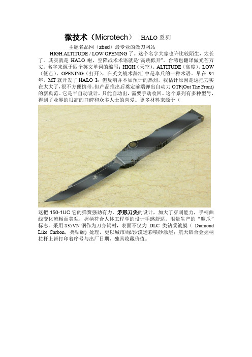
微技术(Microtech)HALO系列主题名品网(zbsd)最专业的做刀网站HIGH ALTITUDE / LOW OPENING了。
这个名字大家也许比较陌生,太长了。
其实就是HALO啦,空降战术术语就是“高跳低开”。
台湾也翻译做光芒万丈。
名字来源于四个英文单词的缩写:HIGH(天空)、ALTITUDE(高度)、LOW (低点)、OPENING(打开),在英文战术辞汇中是伞兵的一种术语。
早在94年,MT就开发了HALO I:但反响并不如预计的热烈,我估计原因是这把刀实在太大了,很不方便携带。
但产品推出后奠定前端弹出自动刀OTF(Out The Front)的新典范。
它是半自动设计,只能自动出,需要手动收回。
这个系列有多种型号,得到了业界的很高的口碑和众多人士的喜爱。
更多材料来源于(这把150-1UC它的弹簧强劲有力,矛形刀尖的设计,加大了穿刺能力,手柄曲线变化流畅而美观,握柄符合人体工程学的设计手感舒适。
限量生产的“鹰爪”标志。
采用S35VN钢作为刀身钢材,表面不仅为DLC 类钻碳镀膜(Diamond Like Carbon,类钻碳) 处理,更以城市/绿/沙漠迷彩喷砂涂层;航天铝合金握柄拉杆上皆打印着序号与出厂日期,独具收藏价值。
这款主题名品上的MICROTECH 美国微技术150-1GR刀刃采用S35-VN 钢材,S35VN 是相对于S30V提高了韧性的一种马氏体不锈钢。
相比S30V,其加工和打磨也更加容易。
由于其均质性和高质量,而比传统工艺生产的钢材具有更好的尺寸稳定性,热处理后几乎不变形。
韧性的提高可以使得刀刃的抗破损能力提高。
柄材是6061-T6航空铝,是一种很常用的高档刀具柄材。
几何刀尖,这种刀尖是目前最多才多艺的刀尖形式了! 最大的优点便是其刀尖强度非常的坚固,几乎不会断裂。
既能配合进行劈砍用,也能进行穿刺。
几何刀尖形成2个刀尖,前面的那个刀尖比较尖锐可以用来刺和刨。
后面的刀尖可以用来割。
microtech
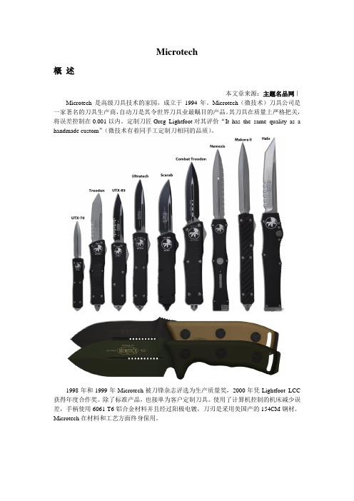
Microtech概述本文章来源:主题名品网|Microtech 是高级刀具技术的家园,成立于1994年。
Microtech(微技术)刀具公司是一家著名的刀具生产商,自动刀是其令世界刀具业最瞩目的产品。
其刀具在质量上严格把关,将误差控制在0.001以内。
定制刀匠Greg Lightfoot对其评价“It has the same quality as a handmade custom”(微技术有着同手工定制刀相同的品质)。
1998年和1999年Microtech被刀锋杂志评选为生产质量奖,2000年凭Lightfoot LCC 获得年度合作奖。
除了标准产品,也接单为客户定制刀具。
使用了计算机控制的机床减少误差,手柄使用6061-T6铝合金材料并且经过阳极电镀,刀刃是采用美国产的154CM钢材。
Microtech在材料和工艺方面终身保用。
中文名:微技术全名:Microtech knives地点:FL, 美国创办年份:1994创办人:Anthony Marfione知名产品:L.C.C. DA,V ector,HALO III,L-UDT,ULTRATECH,SOCOM曾获奖项:1998、1999年Blade 生产品质大奖历史Microtech(微技术)始建于1994年佛罗里达州的Vero Beach,于2005年迁移到宾夕法尼亚的布拉德福德,这里曾是世界第一只ziipo打火机的故乡。
自成立后,微技术推出了革命性的战术刀,并继续保持这种优秀的创新产品的传统,追求卓越的品质。
近些年,微技术不断扩张,壮大中着产品的影响力。
未来,微技术将继续成为这个世界上最好的刀具创新和研发的开拓者!虽然该公司生产许多类型的刀具,比如厨刀、鱼刀、箭头、蝴蝶刀等,但微技术最有名的还是它的战术自动刀。
这些刀有着精密的制造过程,利用强大的弹簧和衬垫,绝不劣质。
Microtech公司和许多著刀匠合作,包括Ernest Emerson、Bob Terzuola、Mick Strider、Walter Brend、Greg Lightfoot和Reese Weiland等。
中文MicroTechII培训-客户培训资料

第三章 机组控制柜
机组控制柜由机组控制器、通讯模块、隔离板组成。 机组控制柜由机组控制器、通讯模块、隔离板组成。
机组控制柜
机组控制器
机组控制器:如图所示, 机组控制器:如图所示,可以通过程序卡上传和下载不同 的程序版本,可以通过DIP拨码开关将其设置为机组控 的程序版本,可以通过 拨码开关将其设置为机组控 制器或压缩机控制器。当中文屏失效时, 制器或压缩机控制器。当中文屏失效时,可以对控制器 进行参数设置。机组控制器装在机组控制柜中。 进行参数设置。机组控制器装在机组控制柜中。
机组控制柜
通讯模块 UCM (Unit Communication module ) 功能是充任Carel pLAN总 功能是充任Carel pLAN总 线与外部计算设备之间 的通讯网关, 的通讯网关,连接在中 文屏和控制器之间进行 通讯协议的转换。 通讯协议的转换。 通讯模块上有4 LED指示 通讯模块上有4个LED指示 灯,结合中文屏上的通 讯页面可以诊断中文屏 和机组控制器的通讯状 况。
机组控制柜
隔离板 功能: 功能: 1.给机组控制器供电; 给机组控制器供电; 给机组控制器供电 2.通讯隔离,抗干扰。 通讯隔离, 通讯隔离 抗干扰。 注: 控制柜供电110V, 控制柜供电 , 控制器供电24V。 控制器供电 。
第四章 压缩机控制柜
用于每台压缩机控制, 用于每台压缩机控制,它在 没有机组控制器或操作界 面时仍可运行。 面时仍可运行。 该控制器安装在与压缩机 相邻的控制柜内。 相邻的控制柜内。
图为中文屏和机组控制柜外观
MicroTechⅡ微机控制 MicroTechⅡ微机控制
图为压缩机控制柜外观
第二章 中文显示屏
micro tec概念

micro tec概念
Micro Tec(微老虎)是一种设备或技术,它结合了微型和高
技术,用于解决各种问题或提供创新解决方案。
它通常指的是微型技术,包括微型机械、微电子、微传感器、微操作器和微加工等。
Micro Tec的概念涉及到在微尺度上制造材料、器件和系统,
以实现更高的效率、更小的尺寸和更低的成本。
它可以应用于多个领域,如医疗、通信、能源、制造业、军事和消费电子等。
微老虎的研发和应用在改善和创新传统行业方面具有重要意义。
例如,在医疗领域,微型技术可以用于制造更小、更精确的医疗设备,以实现无创手术和更精准的疾病诊断。
在通信领域,微型技术可以用于制造更小、更高效的电子设备和传感器,以实现更快速的数据传输和更稳定的网络连接。
总之,Micro Tec(微老虎)是一种融合了微型和高技术的概念,它通过利用微尺度上的优势,提供创新解决方案和改善传统行业。
什么是微米技术50字作文

什么是微米技术50字作文英文回答,Microtechnology, also known as micromachining or microfabrication, refers to the technology that deals with the fabrication of structures and devices with dimensions in the micrometer scale (one millionth of a meter). It involves the use of various techniques, such as lithography, etching, deposition, and bonding, to create intricate and precise structures on a microscopic level.Microtechnology has revolutionized many industries, including electronics, healthcare, and telecommunications. In electronics, it has enabled the miniaturization of electronic components, leading to the development of smaller and more powerful devices, such as smartphones and wearable gadgets. In healthcare, microtechnology has contributed to the advancement of medical devices, such as pacemakers and drug delivery systems, which are smaller, more efficient, and less invasive. In telecommunications,it has facilitated the development of microelectromechanical systems (MEMS), which are used invarious applications, including accelerometers, gyroscopes, and microphones.Microtechnology offers numerous advantages, such as increased functionality, improved performance, and reduced costs. By reducing the size of components and devices, it allows for more functionalities to be integrated into a smaller space. This leads to improved performance and efficiency. Additionally, the mass production capabilities of microtechnology enable economies of scale, resulting in lower production costs.中文回答,微米技术,也被称为微加工或微制造,指的是在微米尺度(一百万分之一米)上制造结构和器件的技术。
- 1、下载文档前请自行甄别文档内容的完整性,平台不提供额外的编辑、内容补充、找答案等附加服务。
- 2、"仅部分预览"的文档,不可在线预览部分如存在完整性等问题,可反馈申请退款(可完整预览的文档不适用该条件!)。
- 3、如文档侵犯您的权益,请联系客服反馈,我们会尽快为您处理(人工客服工作时间:9:00-18:30)。
微技术圣甲虫系列 109-7
主题名品网(zbsd)最专业的做刀网站
在美国,一个创建于1994年的高级刀具生产公司,在1998年和1999
年连续2年被刀锋杂志评选为生产质量奖, 2000年凭Lightfoot LCC获得年度合作奖。
每一把刀都使用了计算机控制的机床减少误差。
他就是Microtech knives 微技术公司。
Microtech公司自创始以来,一直坚持着一个简单的使命:以最大的可能生产最完美的刀。
Microtech的目标是在适应整个刀具界演变的增长和变化过程中实现和保持顶尖质量的刀,追求高质量是Microtech 的首要重点。
Microtech将不断推出新的创新产品,追求卓越,并继续保持世界上最好的开拓创新和创造性设计品牌。
Microtech现有圣甲虫系列,眼镜蛇G-10柄系列,狂飙系列,复仇女生系列,等经典点刀型。
其中著名的 SCARAB(圣甲虫)系列弹簧刀更以优越的设计与工艺,不但同时掳获众多收藏家的心,市面上也纷纷出现外型相仿的弹簧刀,说明了SCARAB(圣甲虫)系列弹簧刀的影响力已无庸置疑。
今天我们就来领一下略SCARAB(圣甲虫)的风采吧!
圣甲虫的确是一款非常优秀的直跳,强健有力,坚实可靠。
外形绝对够酷,内在美也从强劲的直跳中得以展现。
很多国外的雇佣军都选择甲虫作为副刀。
所以市场反响非常好,MT一口气推出了 scara(圣甲虫)单刃、双刃、tanto 3个系列至少二十个以上的甲虫品种,比如109-7 就是一款不错的直跳。
微技术(MICROTECH )109-7采用的是双刃剑型设计,让他比单刃更具有
杀伤力,因刀身为一直线,故可十分精准的刺向你所要伤害的目标,且无须修正刀尖角度。
剑型刀尖的优点是以中央突出之剑脊为中线,两侧对秤开锋。
它那薄、细的刀尖能以最少的力气刺入敌人肉体之,干净利落。
中间有条长长的血槽,使他刀身拥有了2个刀脊加强了刀的强度,在一定程度上也填补了剑型刀强度不足的特点。
S30V的刀身钢材表面以喷砂处理(Bead Blast),S30V 这种不锈钢被喻为现时非常好的造刀钢材,应该是最早应用于刀具的粉末不锈钢.。
钢材的每一部分都很平均使刀锋的韧性、强度表现同一。
喷砂处理后,刀刃显得更大气美观一点,也不易生锈。
握柄架构来自6061-T6铝合金材质。
6061-T6这种材料很轻便,有良好的抗腐蚀性、韧性高及加工后不变形、氧化效果极佳等优良特点。
使用6061-T6可以减轻刀重,方便携带。
阶梯式的开关钮设计使你戴手套时仍可灵活且扎实地使用。
刀柄后面附有一个玻璃敲击器,以备不时之需。
刀柄上有也口袋夹方便你野外休闲的时候携带在腰间。
不管什么时候、什么情况下这款微技术(MICROTECH )109-7都会有出众的表现。
主题名品。