Creepage-Clearance-TECTRAIN04(介绍高压产品爬电距离与电气间隙的计算方式)
北京科锐配电自动化股份有限公司中压开关柜说明书

10kV中压开关柜安装使用说明书北京科锐配电自动化股份有限公司安装使用前请先仔细阅读本说明书开关柜应安装在满足其运行条件的室内。
确保由专职电气人员进行安装、操作和维护。
必须保证现场电气设备的联接条件和工作规程的适用和安全性。
有关开关柜的一切操作,都要遵守说明书中的相应规定。
危险要特别注意说明书中标有这个危险标志的注意事项。
不要超出开关设备在正常工作条件下的技术参数里规定的负载。
说明书应放在所有与安装、操作和维护有关人员能方便地拿到的地方。
用户的专职人员应对所有影响工作安全的事项负责,并正确管理开关设备。
若对本说明书尚有疑问,我们将很高兴为您提供进一步的资讯。
版权所有,禁止将本说明书的全部或部分,以任何形式提供给第三者。
公司保留对提供的数据和图解的更改权力,需更改时,不另行通知。
一、产品概述:.............................................................................................................. 错误!未定义书签。
二、设备运行环境条件:............................................................................................ 错误!未定义书签。
(一)正常使用环境条件: .............................................................................. 错误!未定义书签。
(二)特殊使用环境条件: .............................................................................. 错误!未定义书签。
三、型号说明:.............................................................................................................. 错误!未定义书签。
高压电源说明书
电源可安装在电气柜中,或放置在操作台上。图 2.1 标明了标准电源的尺寸。
高压输出 接地柱
大连泰思曼科技有限公司
319.00 mm
3.1 操作步骤
第 3 章 操作指南
注意
本装置产生可以致命的高压,高压电源的 良好接地是最基本的要求。
A)检查电源上的标牌,确认电源的额定值和你所 要求的一致,泰曼高压电源 TP3072 输入为交流 220V。
经开启,为了您的人身安全请小心操作。缓慢 顺时针旋转电压、频率和脉宽调整电位器,此 时输出电压、频率和脉宽会逐渐升高。输出的 电压值、频率值和脉宽值的对应关系见表 3.1。 注意:在电源使用过程中,建议用户将电压调整电 位器、频率调整电位器和脉宽调整电位器的码盘数 调至“500”的位置,这样电源工作起来会更稳定。 H)用示波器连接电源后面板上的“放电电流信号 测试点”和地“GND”,可以测试出电源放电时, 输出的电流信号的电压是多少。泰思曼的技术 工程师在实验时,测试到输出电流信号的电压 为 4V。 I)关闭高压电源的电源开关或切断高压电源的 220V 电源输入线,可将高压电源彻底关闭。
高压输出和负载上依然有高压静电存在。
WARNING THE VOLTAGE MONITOR ON THE POWER SUPPLY FRONT PANEL DOES NOT READ THE OUTPUT VOLTAGE WHEN THE POWER IS TURNED OFF, EVEN IF A CHARGE STILL EXISTS ON
高压危险测试高压电源须由取得专业资格 的人员进行。
WARNING
HIGH VOLTAGE IS DANGEROUS. ONLY QUALIFIED PERSONNEL SHOULD PERFORM THESE TESTS.
美国Eaton公司SPD系列防电压峰值设备说明书

Eaton’s SPD SeriesFor integration into electrical distribution equipmentIntroductionEaton’s SPD Series surge protective devicesEaton’s SPD Series surge protective devices are the latest and most advanced UL T 14495th Edition certified surge protectors. Units are available integrated within Eaton electrical assemblies, including panel-boards, switchboards, motor control centers, switchgear and bus plugs. Application of SPD Series units throughout a facility will ensure that equipment is protected with the safest and most reliable surge protective devices available.SPD Series units are available in all common voltages and configurations, and also in a variety of surge current capacity ratings from 50 kA to 400 kA. Four feature package options are also available to choose from. ApplicationsThe increasing necessity forfacility-wide surge protectionThe ever-increasing use ofmicroprocessors and othersensitive electronic equipmenthas increased the necessity forfacility-wide surge protection.These sensitive electroniccomponents are used withinmany pieces of equipment,including computers,programmable logic controllers,and other commonly usedelectrical and electronicequipment. Surges can wreakhavoc on equipment, causingcatastrophic failures, processinterruptions and prematureaging leading to failure. Theapplication of surge protectivedevices (SPDs) can mitigateproblems with sensitiveelectronic equipment, keepingthe equipment and the relatedprocesses up and running reliablywithout disruption or damagedue to surge-related events.In addition to externallygenerated surge events, suchas lightning and grid switching,equipment is also susceptible todamage by internally generatedsurges. In fact, the majority ofsurges are generated internallyby commonly used items, suchas fluorescent lighting ballasts,light dimmers, photocopiers, faxmachines and variable frequencydrives. This further reinforces thenecessity for facility-wide surgeprotection applied at all stagesof the electrical distributionsystem, from the electricalservice entrance down to thesingle-phase loads.Standards and certifications• UL 1449 5th Editionrecognized component forthe United States and Canada,covered by UnderwritersLaboratories certificationand follow-up serviceFeatures• Uses thermally protectedmetal oxide varistor (MOV)technology• 20 kA nominal dischargecurrent (In) rating (maximumrating assigned by UL)• 50 kA to 400 kA surgecurrent capacity ratings• Four feature package options• 200 kA short-circuitcurrent rating (SCCR)• Available integrated withinthe following Eaton electricalassemblies: panelboards,switchboards, motorcontrol centers, switchgear,automatic transfer switchesand bus plugs• Can be used for UL 96Acompliance• Can be used for NFPA T 780compliance• Can be used for RoHScompliance• 10-year warranty(15 years with registration)The breadth of the SPDSeries’ features, options andconfigurations ensures that thecorrect unit is available for allelectrical applications, includingservice entrances, distributionswitchboards, panelboards andpoint-of-use applications.The SPD Series makes surge suppression safer than everThe SPD Series employs safety and design features that make surge protection safer than ever. Unlike many surge protective devices, the SPD Series contains no user-serviceable parts or items that require periodic maintenance, such as replaceable surge modules, replaceable fuses, surge counter memory backup batteries or wire lugs that require periodic retightening. Integrated versions of the unit are factory installed, meaning no potential contact with harmful voltages present within the unit is possible.The SPD Series has also taken safety to the next level by using thermally protected metal oxide varistors (MOVs) as its core surge suppression component. These thermally protected MOVs operate in a safe manner, even when subjected to abnormal conditions, suchas temporary overvoltages or high fault current conditions. When one of these conditions exists, the thermally protected MOVs are removed from the circuit quickly and safely before a potentially unsafe condition can occur, with absolutely no discharge of smoke or ionized gases. Usage of this technology eliminates any concerns of damage occurring to other components within the electrical assembly should failure of an integrated SPD occur. Usingthe latest in technology and surge protective device design, the SPD Series provides safe, reliable, worry-free surge protection.The integrated SPD performance advantage Installation conductor lengthis the single most important factor related to an SPD’s performance. Performance decreases as the connected conductor length increases. Integrating the SPD within the electrical assembly provides the best possible surge protection by keeping installation conductor lead lengths as short as possible. Integrating the SPD within an electrical assembly can decrease let-through voltages by hundreds of volts, providing you with the best possible surge protection for sensitive electronic loads.The SPD Series is available asan integrated device withinthe following Eaton electricalassemblies:• Panelboards• Switchboards• Motor control centers• Switchgear• Automatic transfer switches• Bus plugsEnhanced protectionstatus indicatorsThe Eaton SPD Series haselevated the features normallyfound within surge protectivedevices to the next level. Unlikemany surge protectors thatmay have only single-coloredindicators that simply indicatewhether power is applied to thesurge protective device, eachSPD Series unit includes dual- ortri-colored protection statuslight emitting diodes (LEDs)that indicate the true status ofthe protection. On three-phaseunits, if power is removed froma phase, the unit’s protectionstatus LEDs continue to indicatethe status of the protection onthat phase, not the status of thepower applied to the phase. Thisnew feature ensures that theuser is supplied with accurateinformation concerning thestatus of the protection theSPD is supplying on the phase,not the status of the powerapplied to the phase.All units that require a neutralwire connection also containan additional set of dual- ortri-colored LEDs that report thestatus of the protection in theneutral-ground (N-G) protectionmode. Like the phase protectionstatus LEDs, the N-G protectionstatus LEDs also report thetrue status of the protectionin the N-G mode.Although most SPDs on themarket contain N-G modeprotection, they do not monitorand indicate the status ofthe protection in that mode.Specifying the SPD Series’N-G protection mode statusindication feature will ensurethat users are suppliedwith complete and accurateinformation concerning thesurge protective device’sprotection status.20 kA nominal dischargecurrent rating (In)The entire SPD Series productoffering has a nominal dischargecurrent (In) of 20 kA, thehighest achievable rating forthis important parameter. Thisis a new rating for SPDs that isincluded as part of UL 1449 5thEdition testing and certification.This rating provides an indicationof the SPD’s design robustnessand ability to handle a numberof large-magnitude surgesover a short period of timeand remain operational withintested parameters.During Intesting, the SPD issubjected to 15 surges of acurrent magnitude chosen bythe SPD’s manufacturer. Validcurrent magnitude choices forthe test are 20 kA and 10 kA forType 1 SPDs. Valid choices forType 2 SPDs are 20 kA, 10 kA,5 kA and 3 kA. The 15 surgesare then applied at the valuechosen by the manufacturer.Prior to the start of Intesting,a preliminary voltage protectionrating (VPR) is measured. TheVPR is the measured let-throughvoltage of the unit when a6 kV, 3 kA surge is applied. Thisvalue is documented and savedas a reference. After all surgeshave been applied, the VPRis measured once again andcompared to the value that wasrecorded prior to the 15-surgesequence. In order to pass theIntest, the SPD must survive all15 surges, and the measuredpre- and post-VPR values mustbe within ±10% of each other.Choosing an SPD with an Inof 20 kA ensures that yourequipment is being protectedby a unit that will continue tomaintain a high level of surgeprotection performance, evenafter being subjected to multiplehigh-magnitude surges.Industry standards for lightningprotection systems requirethe installed SPDs to have anominal discharge current of20 kA. The 2008 Edition ofNational Fire Protection Agency(NFPA) Standard 780, titled“Standard for the Installation ofLightning Protection Systems,”states the requirement inSection 4.18.3.1.2. UL 2007Edition Standard 96A, titled“Installation Requirements forLightning Protection Systems,”states the requirement inSection 13.1. Choosing an SPDwith an Inof 20 kA will ensurethat compliance with thesestandards can be achieved.SPD Series unitSPD Series unit integratedwithin an Eaton panelboard.In this installation, the SPDSeries is mounted directlyto the panelboard’s busbars. This type of installationwill provide the bestpossible surge protection byminimizing the connectedlead length.The SPD Series is alsoavailable as an integrated unitinterfaced via a circuit breakerresident in the electricalassembly. This installationkeeps connected lead lengthsshort while providing a meansof disconnecting power to theunit quickly and easily.2EATON Surge protective devicesFeature package options The SPD Series provides users with the option of selecting between four feature packages. These feature packages are the basic, standard, standard with surge counter, and Power Xpert ® SPD. The proper feature package can be selected based on the requirements of the application or specification.Basic feature packageThe basic feature package is perfect for applications where basic, cost-effective, safe and reliable surge protection is required but budgets don’t allow for extra, additionalfeatures. Rather than sacrifice performance or safety due to cost, SPD Series units with the basic feature package provide you with high-performing surge protection without sacrificing safety or reliability. The basic feature package provides the same level of surge protection and safety provided by the standard, standard with surge counter, and Power Xpert SPD feature packages minus some of the features found in them. The package contains dual-colored protection status LEDs that report the true status of the protection in each phase/mode. All four-wire plus ground units also contain an additional set of dual-colored protection status LEDs that report the status of the protection in the N-G mode.Standard feature package The standard feature package includes all of the features found in the basic featurepackage, plus an audible alarm with silence button, EMI/RFI filtering, and a Form C relay contact that can be used for remote annunciation of the SPD’s status. The audible alarm activates, and the Form C relay contact changes state when any loss of protection is detected or a fault condition exists with the unit. Should such a condition occur, the audible alarm can be silenced by pressing thesilence button. The EMI/RFI filter provides up to 50 dB of noise attenuation over the range of 10 kHz through 100 MHz. Standard with surge counter feature packageThe standard with surge counter feature package includes all of the features found in the standard feature package plus a six-digit surge counter with a reset button. The surge counter indicates the ongoing count of the number of surges the unit has been exposed to and stores them in nonvolatile memory. Should power to the SPD Series unit be completely interrupted, the surge counter will recall and display the surge count prior to the interruption when power is restored. Unlike many surge protectors, the SPD Series’ surge counter memory feature does not require a backup battery that would requireperiodic replacement in order to achieve its memory functionality.Power Xpert SPD feature packageAll features of the standard with surge counter feature package including advanced monitoring and communication. Power Xpert SPD tracks and records surge events and protection status on your facility’s power system. Power Xpert SPD categorizes surge events on each phase as low, medium and high according to IEEE T standard C62.41.2 and stores them in an event log with time and date stamps. Power Xpert SPD uses Eaton’s Power Xpert architecture for secure Ethernet communications to a webpage, or over Modbus T TCP/IP orBACnet/IP for remote monitoring capabilities. Power Xpert SPD is plug and play compatible with Eaton’s PXG900 Gateway and Power Xpert Dashboard. For more details on Power Xpert SPD, refer to product aid PA158017EN.Side-by-side comparison of the SPD Series’ available feature packagesFeature package Standard with Power Xpert ANeutral-ground protection mode available in applicable voltage configurations only.3EATON Surge protective devicesEaton is a registered trademark.All other trademarks are property of their respective owners.Eaton1000 Eaton Boulevard Cleveland, OH 44122United States © 2023 EatonAll Rights Reserved Printed in USAPublication No. PA01005003E / Z27898September 2023SpecificationsSPD Series catalog number configuration for units integrated into electrical distribution equipmentIntegra tedinstruct ion manualSCAN MEIntegrated technical dataSCAN MEFollow us on social media to get the latest product and support information.。
CHEAPE科技国际有限公司 CR Li-ion 电池说明书
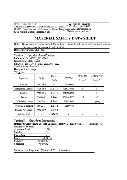
驰普科技国际有限公司CHEAPE TECHNOLOGY INTERNATIONAL LIMITED 801-802, Hisee International Commercial Center, Dongbin Road, Nanshan District, Shenzhen, ChinaTEL : (86) 755- 82581455 FAX : (86) 755-61624235 E-MAIL:**************Website: MATERIAL SAFETY DATA SHEETBoiling Point Specific Gravity (H2O=1)Section VII – First Aid MeasuresFirst Aid proceduresIf electrolyte leakage occurs and makes contact with skin, wash with plenty of water immediatelyIf electrolyte comes into contact with eyes, wash with copious amounts of water for fifteen (15) minutes, and contact a physician.If electrolyte vapors are inhaled, provide fresh air and seek medical attention if respiratory irritation develops. Ventilate the contaminated area.Section VIII - Fire and Explosion Hazard DataFlash Point (Method Used) Ignition Temp. Flammable Limits LEL UELN.A. N.A. N.A. N.A. N.A. Extinguishing MediaCarbon Dioxide, Dry Chemical or Foam extinguishersSpecial Fire Fighting ProceduresN.A.Unusual Fire and Explosion HazardsDo not dispose of battery in fire - may explode.Do not short-circuit battery - may cause burns.Section IX – Accidental Release or SpillageSteps to Be Taken in Case Material is Released or SpilledBatteries that are leakage should be handled with rubber gloves.Avoid direct contact with electrolyte.Wear protective clothing and a positive pressure Self-Contained Breathing Apparatus (SCBA). Section X – Handling and StorageSafe handling and storage adviceBatteries should be handled and stored carefully to avoid short circuits.Do not store in disorderly fashion, or allow metal objects to be mixed with stored batteries.Never disassemble a battery.Do not breathe cell vapors or touch internal material with bare hands.Keep batteries between -30 C and 35 C for prolong storage.Section XI – Exposure Controls / Person ProtectionOccupational Exposure Limits: LTEP STEPN.A. N.A.Respiratory Protection (Specify Type)N.A.Ventilation local exhausts SpecialN.A. N.A.Mechanical(General) OtherN.A N.AProtective glove . Eye protectionN.A. N.A.Other protective clothing or equipmentN.A.Work/Hygienic practiceN.A.ⅫSection Ecological informationN.ASection XIII: Transportation InformationLithium battery international transportation rules. Based on a United Nations recommendation, the regulation for lithium/lithium ion cells and batteries has been revised in the international Air Transport Association (IATA) dangerous goods regulations (54th Edition 2013). Each cell or battery pack meets the requirements of each test in the UN Manual of Tests and Criteria III, sub section 38.3. The Cells / Batteries are "Not Restricted" Cargo.1) Must comply with packing instruction PI965 section II of IATA DGR 54th Edition 2013.2) UN manual of Tests and Criteria, Part III, sub-section 38.32) Watt-hour rating not more than 2.7Wh。
Extech GRT300 4线地电试验仪用户手册说明书

Manual del usuario Telurómetro de 4 hilos Modelo GRT300IntroducciónAgradecemos su compra del telurómetro de 4 hilos de Extech. El probador de tierra Modelo GRT300 se ha diseñado y probado conforme a las especificaciones de seguridad de la Publicación IEC 348, para los Aparatos de Medición Electrónica EN 61010-1, EN 61326-1, EN 61557-1, EN 61557-5 y otras normas de seguridad. El uso y cuidado adecuado de este medidor le proveerá muchos años de servicio confiable.Notas de seguridad•Lea cuidadosamente la siguiente información de seguridad antes de operar o dar servicio al medidor.•Use el medidor sólo como se especifica en este manual. De otra manera, la protección suministrada por el medidor puede ser afectada.•Condiciones ambientales nominales :Uso interior y exterior.Instalación Categoría IV 300V.Grado de contaminación 2.Altitud hasta 2000m.Humedad relativa 80% máx.Temperatura ambiente 0-40°C.Observe la simbología eléctrica internacional enlistada a continuación:El detector está completamente protegido con doble aislante o aislamiento reforzado.¡Advertencia! Riesgo de choque eléctrico.¡Precaución! Consulte este manual antes de usar el detector.Terminal de (masa) tierra.El equipo cumple las directivas vigentes de la Unión Europea.ADVERTENCIAPara evitar choque eléctrico, no toque las terminales durante las pruebasNunca aplique voltaje mayor a 300V a través de las terminales P1 y P2.Características•Controlado por microprocesador con características de seguridad avanzadas •Pantalla LCD de dos líneas• Escalaautomática•Pruebas de resistencia de tierra con cuatro escalas: 0-2Ω/0-20Ω/0-200Ω/0-2kΩ•Escala de medición de voltaje de tierra de 0-300VCA•Prueba automática para punta C.•Prueba automática para punta P.•Prueba de 2 hilos•Prueba de 3 hilos•Prueba de 4 hilos• Apagadoautomático•Retención de datos•Norma de seguridad: EN 61010-1 CATIV 300V, EN 61326-1Descripción del medidor1. TerminalC12. TerminalP1(Conexión de cable de prueba verde) 3. TerminalP24. TerminalC2(Conexión de cable de prueba rojo)5. Pantalla6. RcLED7. RpLED8. Botón 2 hilos9. Botón 3 hilos10. Botón 4 hilos11. Botón VCA12. Botón de encendido13. Botón PRUEBA/PARO 5 6 7OperaciónPrueba de voltaje de batería1. Presione de nuevo el botón "ON/OFF", si en pantalla aparece "Batería débil", reemplace lasbaterías.Medición de voltaje de tierra1. Conecte los cables de prueba como se indica enseguida.(1) Electrodo de tierra (varilla) a prueba (2) Punta de prueba2. Presione el botón "ON/OFF" y espere para “Seleccionar Función” en la pantalla.3. Presione el botón "ACV" y luego el botón "TEST/STOP".4. El voltaje de tierra se presenta en pantalla.Nota: Cuando el voltaje de tierra es mayor a 10V, pueden ocurrir errores en la medición deresistencia de tierra. Asegure que el valor indicado es menor a 10V.Medición de resistencia de tierraNota: El resultado medido puede ser influenciado por acoplamiento inductivo o capacitivo si los cables de prueba están torcidos o adyacentes uno al otro. Al conectar las sondas, mantenga separados los cables.ConfiguraciónInserte la punta de Potencial y la punta de Corriente (si se requiere) tan profundo como sea posible en el suelo. La distancia entre puntas debe ser entre 5 a 10 metros (16 a 32 pies)123 (1) Electrodo de tierra (varilla) a prueba (2) punta de Potencial (3) punta de Corriente123 (1) Electrodo de tierra (varilla) a prueba (2) punta de Potencial (3) punta de Corriente12 (1) Electrodo de tierra (varilla) a prueba (2) punta de PotencialPruebas1. Conecte los cables de prueba para pruebas de 2, 3 ó 4 terminales.2. Presione el botón ON/OFF y espere que abra la pantalla "Seleccionar Función"3. Presione el botón de la configuración "2P", "3P" ó "4P".4. Presione el botón "TEST/STOP" para comenzar la prueba.5. El medidor pitará durante la prueba (aproximadamente 10) y luego la lectura aparece en lalínea inferior de la pantalla.Notas:Indicadores LED "Rc" y "Rp":Rc: Sin salida de Corriente de prueba. Verifique las conexiones.Rp: Si Rp está activo y la pantalla indica "> 2 kΩ", la resistencia de tierra es mayor a 2000Ω.Si, en modo "4P", la pantalla indica "Vp Error", ponga en corto C1 (negro) y P1 (verde). Consideraciones sobre mediciónLas pruebas con 2 terminales son apropiadas para realizar la mayoría de las pruebas en suelos normalmente conductivos. Sin embargo, las mediciones de 2 terminales incluyen cable de pruebas y resistencia de contacto en la medición y el resultado será una lectura ligeramente más alta que la resistencia de tierra verdadera. Cuando los resultados medidos son mayores a lo deseado o si la directiva de medición requiere técnicas multiterminales, cambie a la técnica de 3 ó 4 terminales según sea necesario.Mantenimiento1. Tapa posterior2. Batería3. FusibleReemplazo del fusible 1.Desconecte los cables de prueba del instrumento. 2.Retire los dos tornillos para quitar la tapa. 3.Retire y reemplace el fusible con uno nuevo de igual valor y tamaño 0.1A/250V, 5 x 20mm. 4.Reemplace y asegure la tapa posterior.Reemplazo de la bateríaCuando en pantalla aparezca "Batería débil", reemplace las baterías.1.Desconecte los cables de prueba del instrumento y quite la tapa posterior y las baterías. 2.La batería está bajo el probador. 3.Reemplace con ocho baterías AA de 1.5V para lámpara, tenga cuidado de observar la polaridad correcta. 4.Reinstale el porta-baterías y la tapa.Limpieza y almacenamientoADVERTENCIA: Para evitar choque eléctrico o daño el medidor, no deje que entre agua dentro del estuche.Limpie periódicamente la caja con un paño húmedo y detergente, pero no use abrasivos o solventes. 123EspecificacionesEscalas de medición Resistencia de tierra: 0-2Ω, 0-20Ω, 0-200Ω, 0-2kΩVoltaje de tierra: 0-300V CA (40 a 500Hz) Precisión Resistencia de tierra: ±(2% lect.+3 dígitos)Voltaje de tierra: ±(2% lect.+3 dígitos)Resolución de resistencia de tierra 0-2Ω: 0.01Ω0-20Ω: 0.1Ω0-200Ω: 1 Ω0-2kΩ: 0.01kΩFrecuencia de prueba 820HzCorriente de prueba 2mATemperatura y Humedad Operación: 0 a 50°C (32 a 122°F) 80%R.H.Almacenamiento: -10 a 60°C (14 a 140°F)أ80%R.H.Fuente de tensión 1.5V (AA) x 8Dimensiones 250(L) x 190(W) x 110(D) mm (9.84x7.5x4.33”)Peso Aprox. 1430g (batería incluida)Fusible ( 0.1 A/250V 5 x 20mmCopyright © 2011 Extech Instruments Corporation (Una Empresa FLIR) Reservados todos los derechos, incluyendo el derecho de reproducción total o parcial en cualquier medio.。
高压软起使用手册(奥博)-EN04

AMVS computerized softstarter withChineseDisplayfor MV AC motorUserManualNanjing Aubo Electric Co.LtdProduct Feature:AMVS is the computerized digital soft starter for MV AC motor , with Chinese display. Its system uses the advanced single chip microcomputer, PLC controller and color touch screen HMI and high voltage power electronic semiconductor devices and modern control technology to integrate a new type of product of solid state starter and running protection of MV AC motor. In addition to the excellent starting function, this product also has a perfect comprehensive protection function of the motor running, can ensure that the motor and mechanical transmission equipment running in a safe and reliable operation of the various circumstances. Compared with other types of medium voltage motor soft starter (such as water resistance type), the soft starter consumes less energy in the process of starting , therefore it has the obvious energy saving effect, and itcan be used in the occasion of frequent starting. At the same time, since the soft starter is made of solid state devices, it has the long-term use of free maintenance, and a small equipment size, easy to move and a better vibration resistance as clear advantages. Further more, it has the following unique features and obvious advantages, becoming the ideal replacement of other traditional medium voltage soft starter.1.Starting of initial voltage can be set according to the actualsituation and need flexibly, as low as to 15% of the supply voltage, and the highest could be 90%, make the motor have a larger starting torque and small starting current, reducing the equipment operation requirement for power grid capacity, saving the investment of equipment. Reduce the impact stress to the motor and to the mechanical transimission part itself, and can prolong the service life of motor and transmission machinery.2.When starting, the initial start voltage, the start time andstarting current limit and so on, are available on color LCD touch screen to be easily set up and be implemented, and soft stop deceleration time can be set freely according to the requirementsslowing down and stop condition of equipment and motor.3. variety of starting mode ( reduced voltage starting ,constantcurrent starting) control to meet the various startingperformance requirements of the device.4.Perfect motor running protection function, can ensure the safetyof the equipment operation, protection function are like:a. protection alarm for input supply voltage high.b. protection alarm for input supply voltage low.c. the input power phase loss alarm.d. motor overload alarm for inverse time over current protection .medium voltage motor imbalanced current alarmf. motor start excess time protection alarm.g. the bypass contactor fault alarm.h. residual current leakage alarm for the equipment.i. the main three-phase thyristor power device breakdown damagealarm and display.j. short circuit instantaneous tripping alarm (which can be classified as current transformer range 0.1- 2.5 times current).5.The soft starter shows motor three-phase working current and theresidual current leakage, and the voltage of power supply, anddisplays the total motor running time, which is not affected bypower outages, to facilitate the understanding of the equipmentrunning total time, easy to carry out regular maintenance.6.The running parameters of display are colored Chinese touch screenman-machine interface, easy parameters setting is veryintuitive.7.According to user requirements it can privide profibus dpcommunication interface, and remote monitor computer networkingcommunication at the next higher level and to realize the remotecontrol.(please notify when ordering for other communicationneed)Touch screen panel shows the various parameter setting.The function description:Running time (RUNtime) : 0-9999 hour (H); The count value is for all previousrun time accumulated, after 9999 hours fullvalue, it goes automaticallyback tozero.Every time after restart, the timingcounts again.Start Time: The unit is seconds; 0.1 99.9 seconds (S)Stop Time: The unit is seconds; 0.1 99.9 seconds (S)Overcurrent: The unit is A; it is generally set as about 1.2 times of rated current of motor nameplates.In the process of motorstarting, it doesn't work.When the soft starter goes into runstate, if the motor current is the same or more than the value,the controller will count the timing of inverse timeoverload .When it achieves the time set by overload time, thesoft starter will stop working and generate overload alarmsignal.overload time: 0.1-199.9 seconds (S); When the motor current exceed theset overload current value, such as thetime more than the set time,it producesoverload alarm. This time has theinverse time protection characteristics,that is, when the actual current exceedsthe set overload current value, the greaterthe current, the shorter the protectiontime.start voltage: range: 10-90%; When starting voltage is corresponding to 10% 90% of the power supply voltage , the user can adjustit according to actual situation of devices.Residual current: The unit of the value is A, which is the actual signal detected from the residual current transformer, witha range of 0.01-9.99 A.The value displayed is the actualresidual current detected by the residual currenttransformer, which cannot be modified. When the userreplaces the transformer with different type, he must adjustP4 potentiometer of the control board to calibrate it.Start current limit: The unit is A: the current value is the maximum current value in the process of starting a motor.In theprocess of starting, when the motor starting current reachesthe value, the starter will limit the increase of thestarting current, the starting time value being the biggestprotection time.If due to the reason of too heavy load, thestart can not be completed in the set starting time, thestarter will stop and generate "starting overtime" alarm.If the equipment is normal, this can be resolved byincreasing the current limit value or increasing thestarting time. Please pay attention to this! The largest setvalue shall not exceed two times of the "mutual inductancecurrent" set value! When the start mode is selected as“reduced voltage", the parameter value is invalid.Current leakage protection: The unit of the value is A, with a range of 0.01-9.99 A.The set values is the trigger value ofleakage current protection.When the value is set to 0.00A, the function is invalid.This value is the value detectedby the residual current transducer on the output side ofsoft starter. When the output cable or the medium voltagemotor has a bad insulation to the ground and causes leakagecurrent to ground, if the leakage current detected isgreater than the set value, and duration time is greaterthan the set leakage time, the soft starter will immediatelystop and produce a fault alarm on the display(leakageblocking protection alarm) .When it is used for the firsttime, the value can be set to a maximum first. At the firststarting of equipment, the user should observe the maximumleakage current (usually during start), and the averageleakage current during run. When it comes to stop, set theparameter to a value 20-30% greater than the actual leakagecurrent .Current leakage delay: The unit of the value is second, with a range of 0.1-9.99 second.The set values is the delayvalue of leakage current protection.When the value is setas 0.0 seconds, it is the instantaneous protection action .Due to all kinds of complicated conditions of transmissioncable and medium voltage motor, the leakage current isbigger during start and is smaller during run, so settingthe appropriate time delay of the protection willeffectively avoid mis-operation of the leakage protection,that is, when the leakage current is beyond the above item ,the user should notice this.The leakage time delay functionbecomes invalid once the motor goes into run mode normally.Once the leakage current exceeds the set leakage currentprotection value, the soft starter will immediately stopand produce an alarm on the display (leakage blockingprotection alarm).Over voltage protection: The unit is KV: this parameter is to protect the device from working with too high power supply voltage.Generally it can be set at + 20% to + 25% higher than ratedvoltage .When the supply voltage exceeds the set value, thesoft starter will produce fault alarm on thedisplay.(power supply over voltage alarm)Under voltage protection: The unit is KV: this parameter is to protect the device from working with too low power supply voltage.Generally it can be set at -35% lower than the ratedvoltage .When the supply voltage is below the set value,the soft starter will produce fault alarm on thedisplay.(power supply under voltage alarm)Transducer current: The unit is A: this parameters is the internal transducer data set by manufacturer, which is only to bemodified after the engineer input the password.start mode: Normal mode: in this mode, the motor starts from the "initial voltage", a set low voltage , according to a setstart time to improve output voltage linearly, until theend of start time.Low-frequency mode: especially suitable for the equipmentwith large mechanical friction and larger mechanicalinertia .In this case, the starter starts with 25 hz frequency,making the motor produce large starting torque with smallerstart current , significantly extending the service life ofequipment. (this function is applicable only for users withspecial heavy duty start requirement) To be notify beforeorder.low frequency voltage: The value is the set voltage value of low frequency running.The password for engineer modification : the password is 168.Pressing the reset button will reset the passwordtozero.Description for the fault alarm displayed on the screen in Chinese character :Motor overload alarm: The motor current has surpassed the overloadcurrent protection current value, and time is alsomore than the set overload time delay value .the input power phase loss alarm: There is a phase loss of three-phaseinput power of power controller. The input power shouldbe checked.motor current abnormal alarm: The motor three-phase winding has a phaseloss or three phase current is seriously imbalanced.Excess start time alarm: This is the alarm happening in the processof start, initially activated due to the reason"starting current limit" value is too small or "starttime" value is too short. This can be avoided byincreasing “starting current limit value" or"starting time" value. After normal operation, thealarm is caused by overweighted mechanical load, thereason of which should be find out before next start.Bypass switch fault alarm: When the equipment completes start goes intorun, if the bypass contactor is not closed, that isto say, L1 contact does not connect contact I9, in 5seconds the starter will stop and send the alarm.Alarm for motor residual current leakage: When the leakage current signalof residual current transducer connected with theanalog input port LH1 and LH2 is greater than the setleakage current protection value, the soft starterwill stop and generate this alarm.When a user firstinstalls and uses the equipment, he should carry onthe leakage current range adjustment and calibration.Over voltage of power supply alarm: When the supply voltage exceedsthe "over voltage protection” set value, the powersupply voltage is beyond the protection value.Power supply under voltage alarm: When the supply voltage is belowthe "under voltage protection " set value, the powersupply voltage is beneath the protection value.Power assembly damage alarm: Is there any damage or breaking down ofthyristor pack of phase A, B, C of the starter mainline, it will report an alarm.Attention! When the soft starter conducts the low voltage 380 v commissioning, "protection device" of the keypad should be set as forbidden; otherwise, it will produce a false alarm.Upon the stop caused by the above alarm, after finding out the reason and troubleshooting, pressing (reset) button on the keypad can clear the alarm.Medium voltage soft starter functions and requirements of external terminal serial number:一.Iinput and output for external connectionUPSL; UPSN: input for external 220 v power supply, by connecting the power supply, all controls within the soft starter work swell based on it.AC7; AC8: terminal of the coil control for the soft starter bypass medium voltage vacuum contactor (coil working voltage is AC220V) LH1,LH2: The secondary detecting coil input of the external residual current transducer.COM: input function control common pointI0.0: stop enabling terminal of soft starter; Normally closed contact, disconnecting its connection with COM, soft starter stops.IO.1: start enabling terminal of soft starter; Normally open contact, disconnecting its connection with COM, soft starter starts.I0.2: remote alarm reset terminal; When the port connects with COM , the soft starter stops immediately and goes into the initialization reset. This is used to remove an alarm and the external equipment interlocking protection.I0.3: alarm reset terminal; when this terminal connects with COM, the soft starter stops immediately stops immediately and goes into the initialization reset.. This is used to remove an alarm and the external equipment interlocking protection.I0.4: bypass operation.I0.5: terminal for cabinet door limit interlock ; when the terminal is connected with COM , the start button works; disconnecting htis point will cause the soft start cease to work. interlock protection used for starter panel door safety limitI0.6: external signal enabling terminal, used for both remote and local controlI0.7: control terminal for external interlock protection; Normally open contact, when the point is connected with COM , it can be used as external emergency stop and interlocking protection of the equipment .I1.0: The running signal sent by the main control board.I1.1: Soft starter ready signal sent by the main control board.I1.2: Alarm signal from the main control board.I1.3: input terminal for external remote start signal; when the point is connected with COM , the soft starter will start and run normally , when the point is disconnected with COM disconnect, soft starter stops immediately.I1.4: input terminal for external remote stop signal; when the point is connected with COM , the soft starter stops immediately.Two: Each output port:24 G: common point for output indicator controlQ0.0: vacuum circuit breaker closing indicator.Q0.1: vacuum circuit breaker breaking indicator.Q0.2: indicator for the operation of bypass contactor .When the soft starter switches to bypass this contact closes for bypass operation via vacuum contactor .Q0.3: SCR detection enabling. When there is any damage of SCR, this point sends out a fault signal and stops the motor .Q0.4: fault indicator.Q0.5: start indicator; for MV soft starter, in the process of starting, this point and 24 G have 24 v dc voltage output. When start is overand it runs with bypass operation, the indicator is off.Q0.6: fault reset enabling terminal, used to reset the fault signal of on the main board.Q0.7: main board run enabling terminal, used to control the start signal of the soft starter.Q1.0: indicator for remote control permission of the soft starterQ1.1: operation indicator light; When MV soft starter ends starting , bypass contactor is closed, the operation condition can be viewedby an external indicator.Low voltage commissioning wiring instructions; When you conduct low voltage commissioning for soft starter, you should connect thethree wiring terminal next to the upper incoming terminal onthe back of the starter with the terminal copper screw of main linerespectively. Namely the mentioned three terminals should beconnected respectively with the input A, B, C of the soft starter, and they are connected to 380 v power supply at the same time . Whenthe output of the soft starter R, S, T are connected to motor orresistive load bulb, you can carry out the the low voltage 380 vcommissioning.Attention ! (During the 380v low voltage commissioning, you must switch off the power supply breaker on the 220 v low voltage side of medium voltage transformer !This can prevent AC220V voltage from going to medium voltage power supply side through the medium voltage power transformer !Then connect a 220 v power supply to A21, B21 separately, at the same time, on the touch screen set the power assembly protectionfunction as invalid!Otherwise it will generate false alarm of device damage. )Three .adjustment instruction for the parameters of themain control board, as below:1. The adjustment of short-circuit tripping current; The main controlboard has the instantaneous trip protection function for the short circuit impact of the main line when the starter is working.The calibration adjustment method of the functionis as following;At the main control board current transformer input 1, 6 terminal, givea current signal, while 2 and 3, 4 and 5 are connected.Normally the short-circuit tripping current can be adjusted to 1.6 times that of the CT primary current. After conversion, the current at terminal 1, 6 is 8A, adjust the current to 8 A, then adjust the precision potentiometer P8, measuring the measurement holes DL0 on the right of IC4 , to get the voltage of 2.5 V or so, then adjust the P4 potentiometer, to make the relay next to socket DL1 and DL2 close, plus DL1 and DL2 close, the PLC controller will generate tripping alarm at this time.2. The calibration of residual current protection; Connect terminal2 of LH1-2 socket to the secondary terminal of residual current CT,put a current signal wire through the threading hole of CT, the current value is the residual current to be protected, adjust the precision potentiometer P10 to let the residual current on the touch screen display value being the tested value.3. Initial startup voltage adjustment; In general, this item need notadjustment, by setting the value of start voltage, it's possible to change the motor start voltage .If the start voltage has reached more than 70% , it meets the voltage value of start, at this time you can adjust the P5 potentiometer on the main control board, and measure the UY test hole on the left upper position of the potentiometer, make the voltage to be about 2-5 v. The higher the voltage, the higher voltage the motor start with.all aspects of the wiring diagram of AMVS MV Soft Starter ,please refer to the appended drawings: The requirement for the use of the product:Power supply: three-phase ac 2300-11000 vacThe range of the motor: three-phase medium voltage asynchronous motor. Start number: no more than 10 times per hour, start interval is greater than 6 minutes after the the previous start.Cooling method: natural air cooling or forced air cooling (depending on the size and working conditions).Installation method: fixed installation in the enclosure.Conditions of use: less than 2000 meters above sea level.When it is more than 2000 meters high, you should decrease the rated power and the number of frequent starting.Environment temperature in 25 to + 45 c, relative humidity is not more than 95% (20 c), no condensing.No corrosive gas, no conductive dust.Note:The user can choose corresponding MV Soft Starter according to motorcapacity . The soft starter of large size also can be sometimesused for small capacity motor.Selection of details:AMVS-080-V6-C12:AMVS---enterprise code080 currentV6 voltageC12 control voltageThe man-machine interface touch screen operation display of medium voltage soft starter:Touch screen operation instructions高压软起触摸屏画面共分为五个画面窗口,如下:1、medium voltage soft starter touch screen will be divided into fivescreen window, as follows:Run displayThis picture is mainly used as a display, including three phase current display, overload protection value, protection value for residual current, measured residual current, motor start current limit value, the circuit breaker closing status, preparing, remote/local state and the state of the motor start and run time.Among them the "alarm reset" is a button to click to reset the soft starter; Cabinet door limit can be choose as valid or invalid , i.e., being valid means when the cabinet door is open the soft starter is not allowed to start, if the cabinet door is open in the process of running the motor stops immediately , and it is not allowed to open considering the personal safety .Invalid refers to that when the cabinet door is open, the motor operation is out of control.Click the parameters setting to enter the parameter setup screen, click the alarm content observation to go into the alarm screen, click the control interlock observation to go into the picture of operation interlock.2、parameter settingThis picture is mainly to set some protection function of the soft starter, clickthe corresponding text box below to input value needed to be set.As below:alarm for power supply over voltage: over voltage protection for power supply. Click below text to input the preset value, the factory setting: 12alarm for power supply under voltage: under voltage protection for power supply. Click below text to input the preset value, the factory setting:7Soft start time: motor soft start time, unit Second, click below text to input the preset value, the factory: 10Soft stop time: motor soft stop time, unit Second, click below text to input the preset value, the factory setting:Initial start voltage: motor start voltage, normally set as 20% - 20%; click below the text to input the preset value, the factory setting: 30%overload current protection: 1.3 to 1.5 times of the rated motor currentOverload alarm delay: the factory setting : 0Maximum start current limit: generally as 3-4 times of the rated currentresidual current leakage protection: this function is set according to the ratio of transducer. For example, if the transducer ratio is 100/5, the residual current leakage should be set as 5: while the transducer ratio is 100/1, residual current leakage should be set as 1Click below text to input the preset value, the factory setting: 5The cuurent leakage alarm delay: the factory setting : 0short circuit tripping current: It's a second protection to prevent the motor current from exceeding overload current protection without protection , as a second protection. This function value is set to 3-4 times higher than that of overload protection value.Current transducer:100/5 Click below text to input the preset value, the factory setting: 100Kick start voltage: the factory setting: 0The permitted interval before next start : in order to prevent the loss of SCR withstand voltage and the reducing of the service life due to frequent start of soft starter .This function should be set more than 10 minutes before next start. The time is: preset value * 100 ms factory setting:6000Motor start mode:Click below text to input the preset value, the factory setting: soft startStart load setting: light duty/ heavy duty switchover Click below the text to input the preset value, the factory: light dutyMain circuit SCR detection: to detect the condition of SCR factory setting:detectionParameters change lock: Once this function is clicked, after it displays modification is allowed, it is allowed to modify the above functions; when modification is forbidden, it is possible to modify the function. the factory: modification forbidden3、Equipment alarm displayalarm for power supply voltage too high/ too low3 phase power phase loss alarmMotor current overload alarmabnormal motor current alarmmotor start timeout alarm (i.e., motor stalling)The bypass contactor fault alarmresidual current leakage alarmShort circuit trip alarmA phase SCR alarmB phase SCR alarmC phase SCR alarmThe main control board not readyalarm for cabinet door limit switch open4、operation interlock pictureThis picture is the observation of on/off state of control buttons on the cabinet door and of remote DCS control . Click on the view of PLC's contact to go into the PLC contact observation images, click back to go back to running picture.5、PLC contact observationThis picture is to observe the on/off state of PLC contact, click back to previous page to return to the run interlock picture, click back to initial picture to go to the run picture。
迈特明酷csf-04说明书
迈特明酷csf-04说明书迈特明酷CSF-04是一款高性能的立式冷却塔,广泛应用于工业生产中的冷却系统。
本说明书将详细介绍CSF-04的特性、安装要求、操作方法以及维护保养等相关内容。
一、产品特性:1. 高效冷却能力:CSF-04采用先进的冷却技术,能够有效地降低工业生产中的温度,确保设备高效、稳定的运行。
2. 多功能控制系统:CSF-04具有先进的多功能控制系统,可以根据实际需要进行自动或手动调节,以满足不同的操作要求。
3. 智能化设计:CSF-04采用智能化设计,具有智能故障检测和报警功能,可以及时发现和解决冷却系统中的故障问题,降低生产中的损失。
4. 节能环保:CSF-04采用节能环保的设计理念,能够最大程度地减少能源的消耗,降低碳排放,符合低碳经济的发展趋势。
5. 结构合理:CSF-04的结构合理,易于安装和维护,减少了工作人员的工作强度。
二、安装要求:1. 安装位置:CSF-04应安装在通风良好、无尘且无腐蚀性气体的场所,远离高温源和震源。
2. 安装基础:CSF-04安装需有坚固的基础支撑,以保证设备的稳定运行。
3. 电气连接:根据电气图纸进行正确接线,并进行绝缘保护措施,确保电气安全性。
4. 冷却水管路连接:根据水管路连接图纸,合理布置冷却水管路,确保水流畅通。
三、操作方法:1. 开机操作:操作前先检查电气设备的接线是否正确,然后打开电源开关,启动控制系统。
2. 运行调节:根据实际需要,可通过控制系统进行自动或手动调节,以满足不同的冷却要求。
3. 故障排除:如果发生故障,应按照故障检测指南进行排查,并进行相应的维修和更换。
四、维护保养:1. 清洁保养:定期对CSF-04进行清洁,包括冷却塔的表面、散热网和水箱等部分,以保证冷却效果和设备的寿命。
2. 防冻保护:在寒冷地区使用CSF-04时,要定期检查冷却水的温度,并根据气温调整冷却液的比例,防止冷却塔冻结。
3. 润滑维护:定期检查润滑部件的润滑情况,及时添加或更换润滑油,确保设备的正常运转。
Sensata Technologies GIGAFUSE高压电池快速断开设备说明书
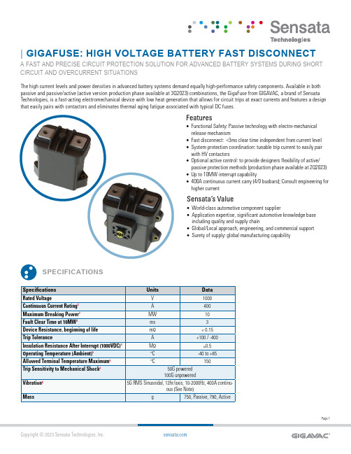
| GIGAFUSE: HIGH VOLTAGE BATTERY FAST DISCONNECTA FAST AND PRECISE CIRCUIT PROTECTION SOLUTION FOR ADVANCED BATTERY SYSTEMS DURING SHORT CIRCUIT AND OVERCURRENT SITUATIONSSPECIFICATIONSUnitsV A MW ms Device Resistance, beginning of life mΩThe high current levels and power densities in advanced battery systems demand equally high-performance safety components. Available in both passive and passive/active (active version production phase available at 3Q2023) combinations, the GigaFuse from GIGAVAC, a brand of Sensata Technologies, is a fast-acting electromechanical device with low heat generation that allows for circuit trips at exact currents and features a design that easily pairs with contactors and eliminates thermal aging fatigue associated with typical DC fuses.FeaturesSensata’s Value• F unctional Safety: Passive technology with electro-mechanical release mechanism • F ast disconnect: <3ms clear time independent from current level • S ystem protection coordination: tunable trip current to easily pair with HV contactors • O ptional active control: to provide designers flexibility of active/passive protection methods (production phase available at 2Q2023)• U p to 10MW interrupt capability • 400A continuous current carry (4/0 busbars); Consult engineering for higher current• W orld-class automotive component supplier • A pplication expertise, significant automotive knowledge base including quality and supply chain • G lobal/Local approach, engineering, and commercial support • S urety of supply: global manufacturing capabilityDIMENSIONSDimensions are in [inches] millimetersTolerance is +/- 0.5mm for all dimensions, unless stated otherwise.MountingM5 or No. 10 ScrewsTorque 1.7 - 4 Nm [15-35in-lb]Case MaterialThermoplastic Polyamide ResinPower ConnectionM8 x 1.25 FemaleTorque 12-18 Nm [106-159 in-lb]Pyro ConnectionTE 411-78033Qualified Acc. to LV 16 and USCARInitiator Resistance: ≥1.7Ω and ≤2.5ΩTriggering Pulse Current: ≥1.75A / 0.5ms≥1.2A / 2.0msDiagnostic Current: ≤100mANo Trigger Current: ≤0.4A or ≤5.0A / 4μsColor of connector retainer may vary due to supplyavailabilitySIDEMOUNTUPRIGHTORDERING OPTIONSMOMENTARY CURRENT CURVE80°C terminal temperature rise at specified curveExample: GFPA415BPassive/Active, 1500A Trip Current, Horizontal Mount OrientationPage 4Sensata Technologies, Inc. (“Sensata”) data sheets are solely intended to assist designers (“Buyers”) who are developing systems that incorporate Sensata products (also referred to herein as “components”). Buyer understands and agrees that Buyer remains responsible for using its independent analysis, valuation, and judgment in designing Buyer’s systems and products. Sensata data sheets have been created using standard laboratory conditions and engineering practices. Sensata has not conducted any testing other than that specifically described in the published documentation for a particular data sheet. Sensata may make corrections, enhancements, improvements, and other changes to its data sheets or components without notice.Buyers are authorized to use Sensata data sheets with the Sensata component(s) identified in each particular data sheet. HOWEVER, NO OTHER LICENSE, EXPRESS OR IMPLIED, BY ESTOPPEL OTHERWISE TO ANY OTHER SENSATA INTELLECTUAL PROPERTY RIGHT, AND NO LICENSE TO ANY THIRD PARTY TECHNOLOGY OR INTELLECTUAL PROPERTY RIGHT, IS GRANTED HEREIN. SENSATA DATA SHEETS ARE PROVIDED “AS IS”. SENSATA MAKES NO WARRANTIES OR REPRESENTATIONS WITH REGARD TO THE DATA SHEETS OR USE OF THE DATA SHEETS, EXPRESS, IMPLIED, OR STATUTORY, INCLUDING ACCURACY OR COMPLETENESS. SENSATA DISCLAIMS ANY WARRANTY OF TITLE AND ANY IMPLIED WARRANTIES OF MERCHANTABILITY, FITNESS FOR A PARTICULAR PURPOSE, QUIET ENJOYMENT, QUIET POSSESSION, AND NON-INFRINGEMENT OF ANY THIRD PARTY INTELLECTUAL PROPERTY RIGHTS WITH REGARD TO SENSATA DATA SHEETS OR USE THEREOF.All products are sold subject to Sensata’s terms and conditions of sale supplied at SENSATA ASSUMES NO LIABILITY FOR APPLICATIONS ASSISTANCE OR THE DESIGN OF BUYERS’ PRODUCTS. BUYER ACKNOWLEDGES AND AGREES THAT IT IS SOLELY RESPONSIBLE FOR COMPLIANCE WITH ALL LEGAL, REGULATORY, AND SAFETY-ELATED REQUIREMENTS CONCERNING ITS PRODUCTS, CONTACT USAmericas+1 (805) 684-8401 *******************GENERAL NOTES1.For customers who can accommodate a vented device, contact Sensata Technologies for more information.2. Current rating (both continuous and momentary) is dependent on bus bar size and customer specific application conditions. Consult with Sensata Technologies for specific details.3. Performance in application will vary based on customer environment and system isolation requirements. Validated at following conditions: 650 V, 15.5kA, 12 µH system inductance. Up to 850 V, 12kA, with 4 µH system inductance. For 1000V application above 3kA, contact Sensata engineering4. Clear time below 5kA can reach up to 4 ms max. IR after 8MW interrupt >1MΩ5. Insulation resistance is dependent on power level of max interrupt load and IR increases with reduced power levels or lower system inductance. IR after standalone short circuit may be below 0.5M at system inductance over 4uH. Performance when tested at system level will show improved IR post interrupt.6. Device can operate in higher ambient temperatures with derated current carry while below maximum terminal temperature.7. Measured on top of the bus bar at the bolted joint. Customer is responsible for ensuring this condition is met otherwise damage to device can occur.8. Sensata Technologies recommends orienting Z axis orthogonal to any mechanical shock pulses to ensure robust performance under load. Sensitivity is dependent on trip setting, consult with Sensata Technologies for more details. See photo for axis orientation.9. Performance depends on specific vibration profile and trip level, consult with Sensata Technologies for your specific requirements. 10. For Automotive Applications please request technical workshop with Sensata Technologies Application Engineering.WARNINGSRISK OF MATERIAL DAMAGE AND HOT ENCLOSURE• The product’s side panels may be hot, allow the product to cool before touching • Follow proper mounting instructions including torque values • Do not allow liquids or foreign objects to enter this productFailure to follow these instructions can result in serious injury, or equipment damage.HAZARD OF ELECTRIC SHOCK, EXPLOSION OR ARC FLASH• Disconnect all power before installing or working with this equipment • Verify all connections and replace all covers before turning on powerFailure to follow these instructions can result in death or serious injury.STRONG MAGNETS PRESENT• This device may present a risk to people with pacemakers if brought within 5 inches (125mm) of device• This device may present a risk to computer drives or other magnetic sensitive electronics or attract small metal tools within 4 inches (100mm) of the device.Failure to follow these instructions can result in death or serious injury.。
OneControl Touch Panel 产品说明书

Level-Up® With OneControl™ Touch PanelOWNER'S MANUALTable of ContentsSystem Information3 Safety Information3 Red/Green LED Indicator 4 Touch Pad Diagram - Auto Leveling Control4 Operation - Auto Leveling Control Touch Pad 5 Unhitching Instructions 5 Auto Level 5 Auto Level Sequence 5 Hitch Recognition - Reconnecting to Tow Vehicle 5 Touch Panel Diagram - MyRV OneControl Touch Panel6 Operation - MyRV OneControl Touch Panel7 Standard Mode and Menu 7 Basic Jack Operation 7 Unhitching Instructions 8 Auto Level 8 Auto Level Sequence 8 Hitch Recognition - Reconnecting to Tow Vehicle 8 Zero Point Calibration 9 To Set the Zero Point 9 Touch Pad Diagram - OneControl App From MyRV10 Operation - OneControl App11 Accessing the OneControl App 11 Standard Mode and Menu 12 Basic Jack Operation 12 Unhitching Instructions 13 Auto Level 13 Auto Level Sequence 13 Touch Pad Diagram - Linc Remote Control - Optional13 Configuring Linc Remote to Sync to MyRV One Control Touch Panel 14 Basic Jack Operation 15 Unhitching Instructions 15 Auto Level 15 Auto Level Sequence 15 Maintenance16 Fluid Recommendation 16 Preventative Maintenance 16 Manual Override 16 Troubleshooting18 Error Display In LCD Screen 18 Level-Up Towable OCTP Assembly19 Level-Up Towable OCTP Components20-26 Notes27System InformationThe LCI Level-Up® OneControl TM Touch Panel is an automatic leveling system control for fifth wheelapplications. It interfaces to the LCI Level-Up pump/jack system to level the trailer. The system utilizes one main control board and a separate waterproof remote level sensor to measure and manage level point, and can be operated from several user interface devices, including:Auto Leveling Control Touch Pad - Mounted outside the trailer within view of the hitch.MyRV® OneControl Touch Panel (OCTP) - Mounted on a wall inside the living space of the trailer.MyRV OneControl Leveling App - The app is available on iTunes® for iPhone® and iPad® and also on Google Play™ for Android™ users. iTunes®, iPhone® and iPad® are registered trademarks of Apple Inc. Google Play™ and Android™ are trademarks of Google Inc.Linc® Remote Control - Optional.The LCI Level-Up OneControl Touch Panel is for fifth wheel applications only.Safety InformationBe sure to park the trailer on solid, level ground. Ensure all jack landing locations are cleared of debris and obstructions and also free of depressions. People and pets should be clear of trailer while operating the leveling system. Ensure the battery of the trailer is fully charged or that the trailer is plugged into shore power prior to attempting to operate the system. Level-Up requires a minimum of 12.75V DC from the battery for proper operation. Be sure to keep hands and other body parts clear of fluid leaks. Hydraulic fluid leaks in the Lippert Leveling System may be under high pressure and can cause serious skin-penetrating injuries.Lippert Components Inc. recommends that a trained professional be employed to change the tires on the trailer. Ensure that the trailer is properly supported with jack stands, or other adequate devices, under the frame of the trailer prior to commencing any service or repair procedure. Any attempts to change the tires or perform other service while trailer is supported solely by the LCI Level-Up could result in death, serious injury,trailer or property damage.DescriptionRed/Green LED - Indicates the status of the system.Up Arrow - Extends front jacks (landing gear).To turn on the touch pad, press the Up and Down arrow buttonsFig. 1 ABCEFDOperation - Auto Leveling Control Touch PadUnhitching InstructionsNOTE: Prior to unhitching from the tow vehicle, ensure trailer is parked on a level surface and chock the tires of the trailer.1. To turn on the touch pad, press both "UP" and "DOWN" arrows (Fig. 1B and Fig. 1C) at the same time.The green indicator LED (Fig. 1A) will turn on.NOTE: The touch pad will remain on as long as the user is pressing buttons. It will time out after approximately 7 minutes without use.2. Press the "UP" arrow (Fig. 1B) to extend the front jacks and lift the front of trailer to take the weight ofthe trailer off of the hitch.3. Uncouple the trailer connection on the tow vehicle.4. Pull tow vehicle away and park at a safe distance.Auto LevelNOTE: Once the automatic leveling cycle has been started, it is important that there is no movement in the trailer until the trailer has completed the leveling process. Failure to remain still during the levelingcycle could have an effect on the performance of the leveling system.1. After unhitching from tow vehicle press "AUTO LEVEL" (Fig. 1D).NOTE: Pressing any button during an Auto Level sequence will abort the auto leveling cycle.Auto Level SequenceNOTE: Sequence may vary slightly based on the height of the trailer king pin prior to leveling.1. When the Auto Level sequence begins, the front of the trailer will seek a position near a level state,then the trailer will level from front to back.2. The left side jack(s) extend to ground (left mid and left rear).3. The right side jack(s) extend to ground (right mid and right rear).4. Jack pairs will extend as needed in order to level the trailer.NOTE: Step 4 may repeat several times if the controller deems necessary.NOTE: If the AUTO LEVEL sequence does not perform as described above, place the system in manual mode and test that the jacks operate correctly by pushing their coordinating buttons on theOneControl Touch Panel inside the trailer; e.g., "FRONT" button operates only the front jacks, etc.See Operation - MyRV OneControl Touch Panel in this manual.Hitch Recognition - Reconnecting to Tow Vehicle1. To turn on the touch pad, press both "UP" and "DOWN" arrows (Fig. 1B and Fig. 1C) at the same time.The green indicator LED (Fig. 1A) will turn on.2. Press "HITCH HEIGHT" (Fig. 1E). The rear jacks will retract.3. The front of the trailer will raise to the height where the auto level sequence was started.NOTE: If the front of the trailer was below level when the Auto Level process was initiated, the hitch recognition feature will retract the rear jacks but will not retract the front jacks to lower the trailerto the initial hitch height. This feature helps prevent injury and/or damage to anything underneaththe trailer.4. Connect tow vehicle and make sure trailer and hitch are connected and locked.5. Press "RETRACT ALL" System will immediately retract all jacks.AFGBCA BUnhitching InstructionsNOTE: Prior to unhitching from the tow vehicle, ensure trailer is parked on a level surface and chock the tires of the trailer.1. Push touch panel “ON/OFF” (Fig. 2K) to turn system on (See "Standard Mode and Menu" to reachstandard mode.)2. Push "EXTEND" (FIG. 2J), then "FRONT" button (Fig. 2) to extend front jacks and lift front of the trailer totake the weight of the trailer off of the hitch.3. Uncouple the trailer connection on the tow vehicle.4. Pull tow vehicle away and park at a safe distance.Auto LevelNOTE: Once the automatic leveling cycle has been started, it is important that there is no movement in the trailer until the trailer has completed the leveling process. Failure to remain still during the levelingcycle could have an effect on the performance of the leveling system.1. After unhitching from tow vehicle press "AUTO LEVEL" (Fig. 2L).NOTE: Pressing "ABORT" during an Auto Level sequence will abort the auto leveling cycle.Auto Level SequenceNOTE: Sequence may vary slightly based on the height of the trailer king pin prior to leveling.1. When the Auto Level sequence begins, the front of the trailer will seek a position near a level state,then the trailer will level from front to back.2. The left side jack(s) extend to ground (left mid and left rear).3. The right side jack(s) extend to ground (right mid and right rear).4. Jack pairs will extend as needed in order to level the trailer.NOTE: Step 4 may repeat several times if the controller deems necessary.NOTE: If the "AUTO LEVEL" sequence does not perform as described above, place the system in manual mode and test that the jacks operate correctly by pushing their coordinating buttons on the touchpanel; e.g., "FRONT" button operates only the front jacks, etc.Hitch Recognition - Reconnecting to Tow Vehicle1. Push touch panel “ON/OFF” (Fig. 2K) to turn system on (See "Standard Mode and Menu" to reachstandard mode.)2. Press "AUTO HITCH" (Fig. 2M). Rear jacks will retract.3. The front of the trailer will raise to the height where the auto level sequence was started.NOTE: If the front of the trailer was below level when the Auto Level process was initiated, the hitch recognition feature will retract the rear jacks but will not retract the front jacks to lower the trailer tothe initial hitch height. This feature helps prevent injury and/or damage to anything underneath thetrailer.4. Connect tow vehicle and make sure trailer and hitch are connected and locked.5. On the Standard Mode screen (Fig. 2) use the "UP" and "DOWN" arrows (Fig. 2B) to scroll to "AUTORETRACT" (Fig. 2F).6. Push “ENTER” (Fig. 2H). System will immediately retract all jacks.A AA ACD EH I J KFront JacksRear JacksFig. 11CEA B DCallout DescriptionA Retract - Retracts front jacks and rear jacks.B Extend - Extends front jacks and rear jacks.C Help - Provides contact information for LCI.D Front Arrow - Operates front jacks.E Left Arrow - Operates left rear jacks.F Right Arrow - Operates right rear jacks.G Rear Arrow - Operates rear jacks.H Auto Level- Initiates Auto Level sequence.IPower Button - Turns remote control on and off.Unhitching InstructionsNOTE: Prior to unhitching from the tow vehicle, ensure trailer is parked on a level surface and chock thetires of the trailer.1. Push "Extend" (Fig. 10I) and "FRONT" buttons (Fig. 10) to extend front jacks and lift front of trailer to take the weight of the trailer off of the hitch.2. Uncouple the trailer connection on the tow vehicle.3.Pull tow vehicle away and park at a safe distance.Auto LevelNOTE: Once the automatic leveling cycle has been started, it is important that there is no movement in thetrailer until the trailer has completed the leveling process. Failure to remain still during the leveling cycle could have an effect on the performance of the leveling system. 1.After unhitching from tow vehicle press "AUTO LEVEL" (Fig. 10J).NOTE: Pressing "ABORT" during an Auto Level sequence will abort the auto leveling cycle.Auto Level SequenceNOTE: Sequence may vary slightly based on the height of the trailer king pin prior to leveling. 1. When the Auto Level sequence begins, the front of the trailer will seek a position near a level state, then the trailer will level from front to back.2. The left side jack(s) extend to ground (left mid and left rear).3. The right side jack(s) extend to ground (right mid and right rear).4.Jack pairs will extend as needed in order to level the trailer.NOTE: Step 4 may repeat several times if the controller deems necessary.NOTE: If the AUTO LEVEL sequence does not perform as described above, place the system in manualmode and test that the jacks operate correctly by pushing their coordinating buttons on the touch panel in manual mode, e.g., "FRONT" button operates only the front jacks, etc.Touch Pad Diagram - Linc Remote Control - OptionalED G F ICA BHFig. 14AFig. 15ABA ANOTE: If the Auto Level sequence does not perform as described above, test that the jacks operatecorrectly by pushing their coordinating buttons on the Linc remote; e.g., "FRONT" button operates only the front jacks, etc. The jacks can also be tested in manual mode on the OneControl Touch Panel (Fig. 2). See Operation - MyRV OneControl Touch Panel.Maintenance Fluid RecommendationAutomatic transmission fluid (ATF) with Dexron ® III or Mercon ® V or a blend of both is recommended by Lippert Components, Inc. For a list of approved fluid specifications, see TI-188. To obtain this Technical Information sheet on-line, go to /support-lci4a3lcd. Then click on the Technical Information Sheets tab. Look for TI-188: Hydraulic Operation Fluid Recommendation within the listing.NOTE: In colder temperatures (less than 10 ° F) the jacks may extend and retract slowly due to the fluid'smolecular nature. For cold weather operation, fluid specially formulated for low temperatures may be desirable.Preventative Maintenance1.Check hydraulic fluid in reservoir every 12 months. If fluid is a clear, red color, do not change. If fluid is milky, pink and murky, and not clear red in color, drain reservoir and add new fluid. Hydraulic fluid in reservoir should be changed a minimum of every five years.NOTE: Check the fluid only when all the jacks are fully retracted.NOTE: When checking the hydraulic fluid level, fill to within 1/4" to 1/2" of fill spout.2. Inspect and clean all power unit electrical connections every 12 months. If corrosion is evident, use a small amount of lubricant to remove corrosion. Contacts must be cleaned with a non-residue cleaner prior to use. LCI recommends the use of an electrical contact cleaner spray.3.Remove dirt and road debris from jacks as needed.4.If jacks are down for extended periods, it is recommended to spray exposed jack rods with a drysilicone lubricant every three months for protection. If the trailer is located in a salty environment, it is recommended to spray the rods every four to six weeks.Manual OverrideThe LCI Level-Up Automatic Leveling System can be manually operated with an electric drill. In the event of electrical or system failure, this manual method of extending and retracting the jacks can be used. See the instructions below.NOTE: Unhook the power unit motor from the power source prior to attempting the manual overrideprocedure.The coach should be supported at both front and rear axles with jack stands before working underneath. Failure to do so may result in death, serious personal injury or severe product orproperty damage.ABAAADO NOT over-tighten override set screws, as this can damage the valves.DO NOT use an impact wrench to perform any of the override procedures, as this mayLCD Message What's Happening?What Should Be Done?"EXCESS ANGLE"Unsecured controller.Uneven or sloped site.Check and secure controller placement.Relocate the trailer."EXCESSIVE ANGLE"Controller not properly secured.Check and secure controller placement.Excessive angle reached during manual operation.Relocate the coach."BAD CALIBRATION"Sensor calibration values are out of range.Replace controller."FEATURE DISABLED"Hitch recognition requested but no hitch height set.Perform "AUTO LEVEL" sequence to establish hitch height.Zero point not set.Set zero point."LOW VOLTAGE"Bad connection or wiring. Discharged or bad battery.Check wiring - repair or replace. Test battery voltage under load - charge or replace."OUT OF STROKE"Unsecured controller.Uneven or sloped site.Check and secure controller placement.Relocate the trailer."EXTERNAL SENSOR"Bad connection or wiring.Replace or repair connection to rear remote sensor."JACK TIME OUT"System could not level in expected time.Check for obstructions, leaks, fluid level and voltage to power unit motor under load. "AUTO LEVEL FAILURE"Unsecured controller.Voltage drop.Check and secure controller placement.Test battery voltage under load - charge or replace."FUNCTION ABORTED"User has aborted an automatic leveling sequence.Restart the sequence.Troubleshooting Error Display In LCD ScreenFaults can only be cleared via the OneControl Touch Panel or OneControl Leveling App through MyRV. The only exception is when the Auto Leveling Control mini-touch pad (Fig. 1) was used to abort an auto-sequence. In this case the fault can be cleared by pressing any Auto Leveling Control button.CDFGHCurrentL RU Gen IYAEAFAGALAPAQAW ANAOBFBIBGDescriptionManifoldRestricted ManifoldRetract Valve BlockNotesThe contents of this manual are proprietary and copyright protected by Lippert Components, Inc. (“LCI”). LCI prohibits the copying or dissemination of portions of this manual unless prior written consent from an authorized LCI representative has been provided. Any unauthorized use shall void any applicable warranty. The information contained in this manual is subject to change without notice and at the sole discretion of LCI.Revised editions are available for free download from .Please recycle all obsolete materials.For all concerns or questions, please contactLippert Components, Inc.Ph: (574) 537-8900 | Web: | Email: ************************。
美国EATON公司保护设备系列微型断路器PLS4、PLZ4(MW)产品说明说明书
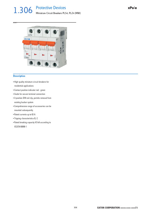
1.306Protective DevicesMiniature Circuit Breakers PLS4, PLZ4 (MW)• H igh-quality miniature circuit breakers for residential applications• Contact position indicator red - green • Guide for secure terminal connection • 3-position DIN rail clip, permits removal from existing busbar system• C omprehensive range of accessories can be mounted subsequently • Rated currents up to 63 A • Tripping characteristics B, C• R ated breaking capacity 4.5 kA according to IEC/EN 60898-1DescriptionSG360111.307Protective DevicesMiniature Circuit Breakers PLS4, PLZ4 (MW)Rated current I n (A)TypeDesignationArticle No.Units perpackage4.5 kA, Characteristic BSG284111PLS4-B124314112/1201.5PLS4-B1,524314212/1201.6PLS4-B1,624314312/1202PLS4-B224314412/1202.5PLS4-B2,524314512/1203PLS4-B324314612/1203.5PLS4-B3,524314712/1204PLS4-B424314812/1205PLS4-B524314912/1206PLS4-B624315012/1208PLS4-B824315112/12010PLS4-B1024315212/12012PLS4-B1224315312/12013PLS4-B1324315412/12015PLS4-B1524315512/12016PLS4-B1624315612/12020PLS4-B2024315712/12025PLS4-B2524315812/12032PLS4-B3224315912/12040PLS4-B4024316012/12050PLS4-B5024316112/12063PLS4-B6324316212/1201-poleSG207111PLZ4-B1/1N2431891/601.5PLZ4-B1,5/1N2431901/601.6PLZ4-B1,6/1N2431911/602PLZ4-B2/1N2431921/602.5PLZ4-B2,5/1N2431931/603PLZ4-B3/1N2431941/603.5PLZ4-B3,5/1N2431951/604PLZ4-B4/1N2431961/605PLZ4-B5/1N2431971/606PLZ4-B6/1N2431981/608PLZ4-B8/1N2431991/6010PLZ4-B10/1N2432001/6012PLZ4-B12/1N2432011/6013PLZ4-B13/1N2432021/6015PLZ4-B15/1N2432031/6016PLZ4-B16/1N2432041/6020PLZ4-B20/1N2432051/6025PLZ4-B25/1N2432061/6032PLZ4-B32/1N2432071/6040PLZ4-B40/1N2432081/6050PLZ4-B50/1N2432091/6063PLZ4-B63/1N2432101/601+N-pole 2MU1.308Protective DevicesMiniature Circuit Breakers PLS4, PLZ4 (MW)Rated current I n (A)TypeDesignationArticle No.Units perpackage SG229111PLS4-B1/22432371/601.5PLS4-B1,5/22432381/601.6PLS4-B1,6/22432391/602PLS4-B2/22432401/602.5PLS4-B2,5/22432411/603PLS4-B3/22432421/603.5PLS4-B3,5/22432431/604PLS4-B4/22432441/605PLS4-B5/22432451/606PLS4-B6/22432461/608PLS4-B8/22432471/6010PLS4-B10/22432481/6012PLS4-B12/22432491/6013PLS4-B13/22432501/6015PLS4-B15/22432511/6016PLS4-B16/22432521/6020PLS4-B20/22432531/6025PLS4-B25/22432541/6032PLS4-B32/22432551/6040PLS4-B40/22432561/6050PLS4-B50/22432571/6063PLS4-B63/22432581/602-poleSG314111PLS4-B1/32432851/401.5PLS4-B1,5/32432861/401.6PLS4-B1,6/32432871/402PLS4-B2/32432881/402.5PLS4-B2,5/32432891/403PLS4-B3/32432901/403.5PLS4-B3,5/32432911/404PLS4-B4/32432921/405PLS4-B5/32432931/406PLS4-B6/32432941/408PLS4-B8/32432951/4010PLS4-B10/32432961/4012PLS4-B12/32432971/4013PLS4-B13/32432981/4015PLS4-B15/32432991/4016PLS4-B16/32433001/4020PLS4-B20/32433011/4025PLS4-B25/32433021/4032PLS4-B32/32433031/4040PLS4-B40/32433041/4050PLS4-B50/32433051/4063PLS4-B63/32433061/403-pole1.309Protective DevicesMiniature Circuit Breakers PLS4, PLZ4 (MW)Rated current I n (A)TypeDesignationArticle No.Units perpackage SG352111PLS4-B1/3N2433331/301.5PLS4-B1,5/3N2433341/301.6PLS4-B1,6/3N2433351/302PLS4-B2/3N2433361/302.5PLS4-B2,5/3N2433371/303PLS4-B3/3N2433381/303.5PLS4-B3,5/3N2433391/304PLS4-B4/3N2433401/305PLS4-B5/3N2433411/306PLS4-B6/3N2433421/308PLS4-B8/3N2433431/3010PLS4-B10/3N2433441/3012PLS4-B12/3N2433451/3013PLS4-B13/3N2433461/3015PLS4-B15/3N2433471/3016PLS4-B16/3N2433481/3020PLS4-B20/3N2433491/3025PLS4-B25/3N2433501/3032PLS4-B32/3N2433511/3040PLS4-B40/3N2433521/3050PLS4-B50/3N2433531/3063PLS4-B63/3N2433541/303+N-poleSG371111PLS4-B1/42433811/301.5PLS4-B1,5/42433821/301.6PLS4-B1,6/42433831/302PLS4-B2/42433841/302.5PLS4-B2,5/42433851/303PLS4-B3/42433861/303.5PLS4-B3,5/42433871/304PLS4-B4/42433881/305PLS4-B5/42433891/306PLS4-B6/42433901/308PLS4-B8/42433911/3010PLS4-B10/42433921/3012PLS4-B12/42433931/3013PLS4-B13/42433941/3015PLS4-B15/42433951/3016PLS4-B16/42433961/3020PLS4-B20/42433971/3025PLS4-B25/42433981/3032PLS4-B32/42433991/3040PLS4-B40/42434001/3050PLS4-B50/42434011/3063PLS4-B63/42434021/304-pole1.310Protective DevicesMiniature Circuit Breakers PLS4, PLZ4 (MW)Rated current I n (A)TypeDesignationArticle No.Units perpackage4.5 kA, Characteristic CSG284110.16PLS4-C0.1624316312/1200.25PLS4-C0,2524316412/1200.5PLS4-C0,524316612/1200.75PLS4-C0,7524316512/1201PLS4-C124316712/1201.5PLS4-C1,524316812/1201.6PLS4-C1,624316912/1202PLS4-C224317012/1202.5PLS4-C2,524317112/1203PLS4-C324317212/1203.5PLS4-C3,524317312/1204PLS4-C424317412/1205PLS4-C524317512/1206PLS4-C624317612/1208PLS4-C824317712/12010PLS4-C1024317812/12012PLS4-C1224317912/12013PLS4-C1324318012/12015PLS4-C1524318112/12016PLS4-C1624318212/12020PLS4-C2024318312/12025PLS4-C2524318412/12032PLS4-C3224318512/12040PLS4-C4024318612/12050PLS4-C5024318712/12063PLS4-C6324318812/1201-poleSG207110.16PLZ4-C0.16/1N2432111/600.25PLZ4-C0,25/1N2432121/600.5PLZ4-C0,5/1N2432141/600.75PLZ4-C0,75/1N2432131/601PLZ4-C1/1N2432151/601.5PLZ4-C1,5/1N2432161/601.6PLZ4-C1,6/1N2432171/602PLZ4-C2/1N2432181/602.5PLZ4-C2,5/1N2432191/603PLZ4-C3/1N2432201/603.5PLZ4-C3,5/1N2432211/604PLZ4-C4/1N2432221/605PLZ4-C5/1N2432231/606PLZ4-C6/1N2432241/608PLZ4-C8/1N2432251/6010PLZ4-C10/1N2432261/6012PLZ4-C12/1N2432271/6013PLZ4-C13/1N2432281/6015PLZ4-C15/1N2432291/6016PLZ4-C16/1N2432301/6020PLZ4-C20/1N2432311/6025PLZ4-C25/1N2432321/6032PLZ4-C32/1N2432331/6040PLZ4-C40/1N2432341/6050PLZ4-C50/1N2432351/6063PLZ4-C63/1N2432361/601+N-pole 2MU1.311Protective DevicesMiniature Circuit Breakers PLS4, PLZ4 (MW)Rated current I n (A)TypeDesignationArticle No.Units perpackage SG229110.16PLS4-C0.16/22432591/600.25PLS4-C0,25/22432601/600.5PLS4-C0,5/22432621/600.75PLS4-C0,75/22432611/601PLS4-C1/22432631/601.5PLS4-C1,5/22432641/601.6PLS4-C1,6/22432651/602PLS4-C2/22432661/602.5PLS4-C2,5/22432671/603PLS4-C3/22432681/603.5PLS4-C3,5/22432691/604PLS4-C4/22432701/605PLS4-C5/22432711/606PLS4-C6/22432721/608PLS4-C8/22432731/6010PLS4-C10/22432741/6012PLS4-C12/22432751/6013PLS4-C13/22432761/6015PLS4-C15/22432771/6016PLS4-C16/22432781/6020PLS4-C20/22432791/6025PLS4-C25/22432801/6032PLS4-C32/22432811/6040PLS4-C40/22432821/6050PLS4-C50/22432831/6063PLS4-C63/22432841/602-poleSG314110.16PLS4-C0.16/32433071/400.25PLS4-C0,25/32433081/400.5PLS4-C0,5/32433101/400.75PLS4-C0,75/32433091/401PLS4-C1/32433111/401.5PLS4-C1,5/32433121/401.6PLS4-C1,6/32433131/402PLS4-C2/32433141/402.5PLS4-C2,5/32433151/403PLS4-C3/32433161/403.5PLS4-C3,5/32433171/404PLS4-C4/32433181/405PLS4-C5/32433191/406PLS4-C6/32433201/408PLS4-C8/32433211/4010PLS4-C10/32433221/4012PLS4-C12/32433231/4013PLS4-C13/32433241/4015PLS4-C15/32433251/4016PLS4-C16/32433261/4020PLS4-C20/32433271/4025PLS4-C25/32433281/4032PLS4-C32/32433291/4040PLS4-C40/32433301/4050PLS4-C50/32433311/4063PLS4-C63/32433321/403-pole1.312Protective DevicesMiniature Circuit Breakers PLS4, PLZ4 (MW)Rated current I n (A)TypeDesignationArticle No.Units perpackage SG352110.16PLS4-C0.16/3N2433551/300.25PLS4-C0,25/3N2433561/300.5PLS4-C0,5/3N2433581/300.75PLS4-C0,75/3N2433571/301PLS4-C1/3N2433591/301.5PLS4-C1,5/3N2433601/301.6PLS4-C1,6/3N2433611/302PLS4-C2/3N2433621/302.5PLS4-C2,5/3N2433631/303PLS4-C3/3N2433641/303.5PLS4-C3,5/3N2433651/304PLS4-C4/3N2433661/305PLS4-C5/3N2433671/306PLS4-C6/3N2433681/308PLS4-C8/3N2433691/3010PLS4-C10/3N2433701/3012PLS4-C12/3N2433711/3013PLS4-C13/3N2433721/3015PLS4-C15/3N2433731/3016PLS4-C16/3N2433741/3020PLS4-C20/3N2433751/3025PLS4-C25/3N2433761/3032PLS4-C32/3N2433771/3040PLS4-C40/3N2433781/3050PLS4-C50/3N2433791/3063PLS4-C63/3N2433801/303+N-poleSG371110.16PLS4-C0.16/42434031/300.25PLS4-C0,25/42434041/300.5PLS4-C0,5/42434061/300.75PLS4-C0,75/42434051/301PLS4-C1/42434071/301.5PLS4-C1,5/42434081/301.6PLS4-C1,6/42434091/302PLS4-C2/42434101/302.5PLS4-C2,5/42434111/303PLS4-C3/42434121/303.5PLS4-C3,5/42434131/304PLS4-C4/42434141/305PLS4-C5/42434151/306PLS4-C6/42434161/308PLS4-C8/42434171/3010PLS4-C10/42434181/3012PLS4-C12/42434191/3013PLS4-C13/42434201/3015PLS4-C15/42434211/3016PLS4-C16/42434221/3020PLS4-C20/42434231/3025PLS4-C25/42434241/3032PLS4-C32/42434251/3040PLS4-C40/42434261/3050PLS4-C50/42434271/3063PLS4-C63/42434281/304-pole1.313Protective DevicesMiniature Circuit Breakers PLS..., PLZ... - T echnical DataSpecifi cations | Miniature Circuit Breakers PLS..., PLZ...Description• High selectivity between MCB and back-up fuse due to low let-throughenergy• Compatible with standard busbar• T win-purpose terminal (lift/open-mouthed) above and below• B usbar positioning optionally above or below• M eets the requirements of insulation co-ordination, distance between con-tacts ≥ 4 mm, for secure isolation• S uitable for applications up to 48 V DC (use PLS6-DC for higher DC voltages)Accessories:Auxiliary switch for subsequent installation ZP-IHK286052ZP-WHK286053Tripping signal switch for subsequent installation ZP-NHK248437Remote control and automatic switching device Z-FW/LP248296Shunt trip release ZP-ASA/..248438, 248439Undervoltage release Z-USA/..248288-248291Compact enclosure KLV-TC-2276240KLV-TC-4276241Additional terminal 35 mm2Z-HA-EK/35263960Switching interlock Z-IS/SPE-1TE274418Technical DataPLS..., PLZ...ElectricalDesign according toIEC/EN 60898-1Current test marks as printed onto the deviceRated voltage U n AC: 230/400 VDC: 48 V (per pole, max. 2 poles)Rated frequency50/60 HzRated breaking capacity according to IEC/EN 60898-1I cnPLSM, PLZM10 kAPLS6, PLZ6 6 kAPLS4, PLZ4 4.5 kACharacteristic B, C, DBack-up fusePLSM, PLZM max. 125 A gLPLS6, PLZ6max. 100 A gLPLS4, PLZ4max. 80 A gLSelectivity class3Enduranceelectrical components≥ 10,000 switching operationsmechanical components≥ 20,000 switching operationsLine voltage connection at will (above/below)MechanicalFrame size45 mmDevice height80 mmDevice width17.5 mm per pole (1MU)26.3 mm: device 1P+N (1.5MU)Mounting quick fastening with 3 lock-in positions on DIN rail IEC/EN 60715Degree of protection IP20Upper and lower terminals open mouthed/lift terminalsTerminal protection fi nger and hand touch safe, DGUV VS3, EN 50274Terminal capacity1-25 mm2(1p+N, 1,5TE)1-25 mm2 / 1-16 mm2 (N)Terminal torque2-2.4 Nm(1p+N, 1,5TE)2-2.4 Nm / 1.2-1.5 Nm (N)Busbar thickness 0.8 - 2 mm (except N 0.5MU)Mounting independent of position1.314Protective DevicesMiniature Circuit Breakers PLS..., PLZ... - T echnical DataConnection diagrams1-pole 1+N-pole(1.5MU)1+N-pole(2MU)2-pole3-pole 3+N-pole4-poleDimensions (mm)3 3 1 7(33 1 33 1 7( 3Tripping Characteristics (IEC/EN 60898-1)1+N-pole (1.5MU)1+N-pole (2MU)Quick-acting (B), slow (C), very slow (D)Tripping characteristic B Tripping characteristic C Tripping characteristic D TRIPPING CURRENT TRIPPING CURRENT TRIPPING CURRENT1.315Protective DevicesMiniature Circuit Breakers PLS..., PLZ... - T echnical Data Effect of the Ambient Temperature on Thermal Tripping Behaviour Effect of Power FrequencyEffect of power frequency on the tripping behaviour I MA of the quick releaseLoad Capacity of Series Connected Miniature Circuit BreakersPower frequency f [Hz]162/35060100200300400I MA (f)/I MA (50 Hz) [%]91100101106115134141Adjusted rated current values according to the ambient temperatureNumber of devices (n) 1-pole1.325Protective DevicesMiniature Circuit Breakers PLS4 - T echnical Data Let-through Energy PLS4Let-through Energy PLS4, Characteristic B, 1-poleLet-through Energy PLS4, Characteristic C, 1-poleShort Circuit Selectivity PLS4 towards DII-DIV fuse linkIn case of short circuit, there is selectivity between the miniature circuit breakers PLS4 and the upstream fuses up to the specifi ed values of the selectivity limit current I s [kA] (i. e. in case of short-circuit currents I ks under I s only the MCB will trip, in case of short circuit currents above this value both protective devices will respond).*) basically in accordance with EN 60898-1 D.5.2.bShort circuit selectivity Characteristic B towards fuse link DII-DIV *)Short circuit selectivity Characteristic C towards fuse link DII-DIV*)PLS4DII-DIV gL/gG I n [A]10162025355063801001.0<0.51) 1.2 4.52) 4.52) 4.52) 4.52) 4.52) 4.52) 4.52)1.5<0.51) 1.0 4.52) 4.52) 4.52) 4.52) 4.52) 4.52) 4.52)2.0<0.51)<0.51)0.8 1.6 4.52) 4.52) 4.52) 4.52) 4.52)2.5<0.51)<0.51)0.8 1.5 4.52) 4.52) 4.52) 4.52) 4.52)3.0<0.51)<0.51)0.8 1.4 4.52) 4.52) 4.52) 4.52) 4.52)3.5<0.51)<0.51)0.7 1.3 4.52) 4.52) 4.52) 4.52) 4.52)4<0.51)<0.51)0.6 1.0 3.6 4.52) 4.52) 4.52) 4.52)1)1)2)2)2)PLS4DII-DIV gL/gG I n [A]10162025355063801000.75 1.0 4.52) 4.52) 4.52) 4.52) 4.52) 4.52) 4.52) 4.52)1.0<0.51) 1.2 4.52) 4.52) 4.52) 4.52) 4.52) 4.52) 4.52)1.5<0.51)<0.51) 1.0 2.2 4.52) 4.52) 4.52) 4.52) 4.52)2.0<0.51)<0.51)0.8 1.6 4.52) 4.52) 4.52) 4.52) 4.52)2.5<0.51)<0.51)0.8 1.4 4.52) 4.52) 4.52) 4.52) 4.52)3.0<0.51)<0.51)0.80.9 4.52) 4.52) 4.52) 4.52) 4.52)3.5<0.51)<0.51)0.60.9 2.2 4.52) 4.52) 4.52) 4.52)4<0.51)<0.51)0.60.8 1.8 3.6 4.52) 4.52) 4.52)1)1)2)2)2)1) Selectivity limit current I sunder 0.5 kA2) S electivity limit current I s = rated breaking capacity I cn of the MCBDarker areas: no selectivityProspective short-circuit current [A]L e t t h r o u g h e n e r g y I 2t [A 2 s e c ]Prospective short-circuit current [A]L e t t h r o u g h e n e r g y I 2t [A 2 s e c ]1.326Protective DevicesMiniature Circuit Breakers PLS4 - T echnical DataShort Circuit Selectivity PLS4 towards D01-D03 fuse linkIn case of short circuit, there is selectivity between the miniature circuit breakers PLS4 and the upstream fuses up to the specifi ed values of the selectivity limit current I s [kA] (i. e. in case of short-circuit currents I ks under I s only the MCB will trip, in case of short circuit currents above this value both protective devices will respond).*) basically in accordance with EN 60898-1 D.5.2.bShort circuit selectivity Characteristic B towards fuse link D01-D03*)Short circuit selectivity Characteristic C towards fuse link D01-D03*)PLS4D01-D03 gL/gG I n [A]10162025355063801001.0<0.51) 4.52) 4.52) 4.52) 4.52) 4.52) 4.52) 4.52) 4.52)1.5<0.51) 4.1 4.52) 4.52) 4.52) 4.52) 4.52) 4.52) 4.52)2.0<0.51)<0.51)0.6 1.0 4.52) 4.52) 4.52) 4.52) 4.52)2.5<0.51)<0.51)0.6 1.0 4.52) 4.52) 4.52) 4.52) 4.52)3.0<0.51)<0.51)0.5 1.0 4.52) 4.52) 4.52) 4.52) 4.52)3.5<0.51)<0.51)0.50.9 4.52) 4.52) 4.52) 4.52) 4.52)1)1)2)2)2)2)PLS4D01-D03 gL/gG I n [A]10162025355063801000.75<0.51) 4.52) 4.52) 4.52) 4.52) 4.52) 4.52) 4.52) 4.52)1.0<0.51) 4.52) 4.52) 4.52) 4.52) 4.52) 4.52) 4.52) 4.52)1.5<0.51)0.50.60.9 4.52) 4.52) 4.52) 4.52) 4.52)2.0<0.51)<0.51)0.50.7 4.52) 4.52) 4.52) 4.52) 4.52)2.5<0.51)<0.51)0.50.7 4.52) 4.52) 4.52) 4.52) 4.52)3.0<0.51)<0.51)<0.51)0.6 1.9 4.52) 4.52) 4.52) 4.52)3.5<0.51)<0.51)<0.51)0.6 1.8 4.52) 4.52) 4.52) 4.52)1)1)1)2)2)2)Short circuit selectivity Characteristic B towards fuse link NH-00*)Short circuit selectivity Characteristic C towards fuse link NH-00*)PLS4NH-00 gL/gG I n [A]1620253235405063801001251601.00.9 4.52) 4.52) 4.52) 4.52) 4.52) 4.52) 4.52) 4.52) 4.52) 4.52) 4.52)1.50.8 4.52) 4.52) 4.52) 4.52) 4.52) 4.52) 4.52) 4.52) 4.52) 4.52) 4.52)2.0<0.51)0.5 1.0 2.5 4.52) 4.52) 4.52) 4.52) 4.52) 4.52) 4.52) 4.52)2.5<0.51)0.5 1.0 2.3 4.52) 4.52) 4.52) 4.52) 4.52) 4.52) 4.52) 4.52)3.0<0.51)0.50.9 2.1 4.52) 4.52) 4.52) 4.52) 4.52) 4.52) 4.52) 4.52)3.5<0.51)0.50.9 1.8 4.52) 4.52) 4.52) 4.52) 4.52) 4.52) 4.52) 4.52)4<0.51)<0.51)0.8 1.3 2.3 4.3 4.52) 4.52) 4.52) 4.52) 4.52) 4.52)5<0.51)<0.51)0.7 1.1 1.6 2.2 3.6 4.52) 4.52) 4.52) 4.52) 4.52)6<0.51)<0.51)0.7 1.1 1.5 2.0 3.3 4.3 4.52) 4.52) 4.52) 4.52)1)<0.51)0.61.0 1.3 1.72.63.34.52) 4.52) 4.52) 4.52)PLS4NH-00 gL/gG I n [A]1620253235405063801001251600.75 4.52) 4.52) 4.52) 4.52) 4.52) 4.52) 4.52) 4.52) 4.52) 4.52) 4.52) 4.52)1.00.9 4.52) 4.52) 4.52) 4.52) 4.52) 4.52) 4.52) 4.52) 4.52) 4.52) 4.52)1.5<0.51)0.6 1.3 4.2 4.52) 4.52) 4.52) 4.52) 4.52) 4.52) 4.52) 4.52)2.0<0.51)0.6 1.0 2.5 4.52) 4.52) 4.52) 4.52) 4.52) 4.52) 4.52) 4.52)2.5<0.51)0.5 1.0 2.1 4.52) 4.52) 4.52) 4.52) 4.52) 4.52) 4.52) 4.52)3.0<0.51)<0.51)0.7 1.2 1.8 2.6 4.52) 4.52) 4.52) 4.52) 4.52) 4.52)3.5<0.51)<0.51)0.7 1.1 1.7 2.4 4.2 4.52) 4.52) 4.52) 4.52) 4.52)4<0.51)<0.51)0.7 1.0 1.5 2.1 3.6 4.52) 4.52) 4.52) 4.52) 4.52)5<0.51)<0.51)0.60.8 1.2 1.7 2.8 3.8 4.52) 4.52) 4.52) 4.52)6<0.51)<0.51)0.50.8 1.2 1.5 2.5 3.3 4.52) 4.52) 4.52) 4.52)1)<0.51)0.50.8 1.1 1.5 2.3 2.9 4.52) 4.52) 4.52) 4.52)。
EasySpeed 电容热抵 清洁铁GC1740 20 说明书

EasySpeedSteam boost up to 90 gNon-stick soleplateAnti-scaleGC1740/20Easy and effective4 steam settings for better ironing resultsEasySpeed iron makes you are your ironing easy and effective with lots of steamto remove tough creases, non-stick soleplate for easy gliding on all fabrics, CalcClean function for durable performance.Longer lifetimeCalc Clean slider for durable steam performanceEase of use220 ml water tank for longer ironing sessionsLarger soleplate to cover more in one go*Triple precision tip to reach the most tricky areasWider hole for easy water filling*Non-stick soleplate for easy and fast gliding on all fabricsEffective resultsIntegrated water spray evenly moistens the fabricSteam boost up to 90 g to remove tough creasesContinuous steam up to 25g/min for good crease removalPower up to 2000 W enabling constant high steam outputVariety of settings4 steam settings for better results on different fabricsHighlightsEasy water fillingWider hole for easy water filling*220 ml water tankLess refilling with the extra-large 220 ml water tank so you can iron more clothes in one go.Non-stick soleplateThe soleplate of your Philips iron is coated with a special non-stick layer for good gliding performance on all fabrics.Larger soleplateLarger soleplate to cover more in one go*Triple precision tipThe tip of this Philips iron is precise in 3 ways:it has a pointed tip, button groove and a sleek design of the nose. Triple Precision tip enables you to reach even into the most tricky areas,e.g. around the buttons or between the pleats.Continuous steam up to 25g/minContinuous steam up to 25g/min for good crease removal.Steam boost up to 90 gSteam boost up to 90 g to remove tough creasesIntegrated water sprayThe spray function produces a fine mist that evenly moistens the fabric, making it easier to iron out creases.Power up to 2000 WPower up to 2000 W enables constant high steam output.4 steam settings4 steam settings for better results on different fabricsCalc Clean sliderThis steam iron can be used with normal tap water and the calc clean slider makes it easy to remove any built-up scale out of your iron.To maintain the performance of your Philips steam iron, you should use this scale clean function once a month when using normal tap water.SpecificationsDesign and finishing Color: Light blueEasy to useSoleplate name: Non-stick SprayWater tank capacity: 220 ml Fast crease removalContinuous steam: 25 g/minPower: 2000 WSteam boost: 90 gVariable steam levelsGuarantee2 year worldwide guaranteePowerOn mode (ECO mode): .Scale managementDescaling and cleaning: Built-in Calc CleanSliderT echnical specificationsCord length: 1.9 mHeating time: 30 sec* Than predecessor range Comfort© 2019 Koninklijke Philips N.V.All Rights reserved.Specifications are subject to change without notice. Trademarks are the property of Koninklijke Philips N.V. or their respective owners.Issue date 2019‑09‑30 Version: 3.0.2。
Altech Corp. 产品介绍 - 金冠电气有限公司说明书

FERRULESINTRODUCTIONFerrules insure reliable electrical connections when terminating stranded flexible wire in terminal blocks, circuit breakers or other control devices.Using ferrules offers several advantages:ELIMINATE CROSS SHORTINGcaused by unraveled stray wire strands.IMPROVE TERMINAL CONNECTIONSand reduce resistance by providing a solid surfaceat the point of connection.REDUCE INSTALLATION TIMEby eliminating the need to dress loose wire strandsand facilitating wire insertion into the terminal clamp.PREVENT CONDUCTOR BREAKAGEdue to bending, wire stress or vibration.Recommended Installation ProcedureThe wire should be cut as squarely and evenly as possible, taking careto avoid angular cuts or damage to the conductor. The strip length ofthe insulation will depend on the barrel length of the ferrule and the out-side diameter of the wire.Ideally the wire insulation should be stripped to a length that allows theconductor end to reach flush to the tip of the ferrule, when inserted. Theend of the conductor should not extend more than .5mm past the tip ofthe ferrule.The wire can then be inserted into the ferrule. The wire should be pushedin so that the insulation edge is fully covered by the plastic collar. Theconductor should completely fill the metal tube and can extend up to.5mm past the tip.The finished installation should then be checked for any obvious flawsin processing. An occasional pull test should be preformed to checkthat the crimp tool is functioning properly.After the insulation is stripped, the strands of the conductor should bedressed by slightly twisting them to insure that any stray strands areconsolidated.The ferrule and wire should be crimped with an appropriately sizedratcheted crimper. The ferrule should be inserted into the crimper dieset and positioned so that only the metal tube is crimped. The crimpingtool should be cycled completely to insure proper application.Cutting and stripping the wire<.5 mmFERRULESHIGHLIGHTSble wire in terminal blocks,circuit breakers or other control devices. Insulated ferrules prevent conductor breakage due to bending,wire stress or vibration while facilitating wire inser-tion into the terminal clamp.Altech’s UL insulated fer-rules are color coded by conductor size for conven-ient identification.To ensure efficient ferrule crimping, always select the smallest ferrule diameter that fits the wire and use only professional crimping tools.In order meet the UL re-quirements only matching UL crimpers should be use.S 1S 2D 1D 2L 2L 1Standard PackagingFERRULESConductor AWG 24 22 20 18 18 1614 12 10 8 6 4 2 0 00 000 250 300 350 500 600 kcmil kcmil kcmil kcmil kcmil 95 120 150 185 240 300351 427 427 503 578 5788 6 4 210 16 25 3590 100 135 19020.222.530.342.7FEATURESFerrules insure reliableelectrical connections when terminating stranded flexi-ble wire in terminal blocks,circuit breakers or other control devices. Insulated ferrules prevent conductor breakage due to bending,wire stress or vibration while facilitating wire inser-tion into the terminal clamp.Altech’s UL insulated fer-rules are color coded by conductor size for conven-ient identification.To ensure efficient ferrule crimping, always select the smallest ferrule diameter that fits the wire and use only professional crimping tools.In order meet the UL re-quirements only matching UL crimpers should be use.Pull-Out Force Minimum Values for DINMinimum values of pull-out forces for FERRULES according to DIN EN 60947-1:2008, DIN EN 60999-1:2000 and DIN EN 60999-2:2004Pull-Out Force Minimum Values for UL486FCRIMPERS FOR UL FERRULESFERRULESCrimpit F 4Crimping tool for ferrules (according to DIN 46228 part 1 and 4) with or without plastic collars.Only one crimping profile for the entire cross-section range.Ferrules:0,5 – 4 mm 2(20 – 12 AWG)Twin Ferrules:2 x 0.5 – 2 x 2.5 mm 2(2 x 20 – 2 x 14 AWG)Cat. No.: Crimpit F 4Weight 448 gCrimpit F 6 AutoCrimping tool for ferrules (according to DIN 46228 part 1 and 4) with and without plastic collars. Feeding from front.Ferrules:0,5 – 6 mm 2(20 – 10 AWG)Twin Ferrules:2 x 0.5 – 2 x 2.5 mm 2(2 x 20 – 2 x 14 AWG)Cat. No.: Crimpit F 6 Auto Weight 426 gCrimpit F 6 GyraCrimping tool for ferrules (according to DIN 46228 part 1 and 4) with and without plastic collars.Rotatable crimp die for feeding from the front or the side.Ferrules:0,14 – 6 mm 2(26 – 10 AWG)Twin Ferrules:2 x 0.5 – 2 x 4 mm 2(2 x 20 – 2 x 12 AWG)Cat. No.: Crimpit F 6 Gyra Weight 428 gCrimpit F 6 ENCrimping tool for ferrules (according to DIN 46228 part 1 and 4) with and without plastic collars.Crimp conforms to EN 60947-1. Five crimping profiles for the rated conductor cross-sections.Registration in accordance with VG 95211 (Military designation VG 95236 T 14 A 0001).Ferrules:0.25 – 6 mm 2(24 – 10 AWG)Twin Ferrules:2 x 0.75 – 2 x 4 mm 2(2 x 18 – 2 x 12 AWG)Cat. No.: Crimpit F 6 EN Weight 423 gThese crimpers are specifically designed for use with ferrules and have been tested with our UL Recognized ferrules to insure proper termination. In order to meet the UL requires, the correct sized crimper from this range should be used.Crimpit F 6 LCrimping tool for ferrules (conforming to DIN 46228 part 1 and 2) with and without insulating col-lar. Five crimping profiles depending on the wire cross-sections.Ferrules:0.5 – 6 mm 2(20 – 10 AWG)Twin Ferrules:2 x 0.75 – 2 x 4 mm 2(2 x 18 – 2 x 12 AWG)Cat. No.: Crimpit F 6 L Weight 335 gCRIMPERS FOR UL FERRULESCrimpit F 16Crimping tool for ferrules (according to DIN 46228 part 1 and 4) with and without plastic collars.Crimp conforms to EN 60947-1. Three crimping profiles for the rated conductor cross-sections.Registration in accordance with VG 95211 (Military designation VG 95236 T 14 A 0002).Ferrules:6 – 16 mm 2(10 – 6 AWG)Cat. No.: Crimpit F 16Weight 418 gCrimpit F 16 LCrimping tool for ferrules (according to DIN 46228 part 1 and 4) with and without plastic collars.Crimp conforms to EN 60947-1. Three crimping profiles for the rated conductor cross-sections.Ferrules:6 – 16 mm 2(10 – 6 AWG)Cat. No.: Crimpit F 16 L Weight 380 gCrimpit F 25 LCrimping tool for ferrules (according to DIN 46228 part 1 and 4) as well as for twin ferrules.Ferrules:6 – 25 mm 2(10 – 4 AWG)Twin Ferrules:2 x 4 – 2 x 10 mm 2(2 x 12 – 2 x 8 AWG)Cat. No.: Crimpit F 25 L Weight 540 gSingle WireDual WireCrimpitCrimpit Crimpit Crimpit Crimpit Crimpit Crimpit Crimpit F4F6 Gyra F6 EN F6 AutoF6L F16/F16L F25LF50LAWG mm² AWG mm²26 0.14 24 0.25 22 0.34 20 0.5 18 0.75 2 x 22 2 x 0.34 18 1.0 2 x 20 2 x 0.5 16 1.5 2 x 18 2 x 0.75 14 2.5 2 x 16 2 x 1.5 12 4 2 x 14 2 x 2.5 10 6 2 x 12 2 x 4 8 10 2 x 8 2 x 6 6 16 4 25 2 x 62 x 102 35 1 50Crimper Selection GuideCrimpit F 50 LCrimping tool for ferrules (according to DIN 46228 part 1 and 4) as well as for twin ferrules.Ferrules:35 – 50 mm 2(2 – 1 AWG)Twin Ferrules:2 x 16 mm 2(2 x 6 AWG)Cat. No.: Crimpit F 50 L Weight 540 gCRIMPIT F MULTI AND CRIMPING MACHINESFERRULESCrimpit F MultiMulti-function tool. Stripping and cutting of wires. Crimping tool for insulated belt-strip ferrules according to DIN 40228.Cross-section:0.5 – 2.5 mm 2(20 – 14 AWG)Ferrules:0.5 x 2.5 mm 2(20 x 14 AWG)Cat. No.: Crimpit F Multi Weight 200 gCutter, Stripper and CrimperThis one tool will cut and strip the wires and uses belt feed ferrules for fast and easy installation.20 0.5 8 FII2008BFID2008B 10 x 50 18 0.75 8 FII1808WB FID1808GRB 10 x 50 18 1 8 FII1808YB FID1808RB 10 x 50 16 1.5 8 FII1608BFID1608B 10 x 50 142.58FID1408B10 x 50blue orange white yellow redwhite grey redblack Std.Pack Industry StandardcolorCat. No.colorCat. No.DIN StandardBarrel Length(mm)AWGmm 2AUTOMATED FERRULE CRIMPING MACHINESUL Recognized Insulated Belt Strip FerrulesFor technical and ordering information regardingFerrule Crimping Machines please contact Altech.FERRULES124Gray2402.0122012 3.2 5.4500/10012 4Gray2209.0182618 3.2 5.4100106Black2210.0122012 3.9 6.9100106Black2211.0182618 3.9 6.9100810Ivory2212.0122212 4.98.4100810Ivory2213.0182818 4.98.4100616Green2214.0122412 6.29.6100616Green2215.0182818 6.29.6100425Brown2267.01830187.712.0504 25Brown2272.02236227.712.050235Beige2276.01830188.713.550235Beige2390.02539258.713.550150Olive2500.020362010.916.0502/070Yellow2786.020372013.417.0253/095Red2787.025442515.419.054/0120Blue2788.027482717.622.425250MCM150Yellow2789.032583220.525.025* Different standard packs are available as shown. To order the desired standard pack, please use the quantity required as a suffix to the cat. no. Example for 100 standard pack: Cat. No. 2620.0/100CRIMPERSELECTORGUIDEpage 18FEATURESFerrules insure reliable electri-cal connections when terminat-ing stranded flexible wire in terminal blocks, circuit break-ers or other control devices. In-sulated ferrules prevent conductor breakage due to bending, wire stress or vibra-tion while facilitating wire inser-tion into the terminal clamp.Altech’s standard insulated fer-rules are color coded by con-ductor size for convenient identification.To ensure efficient ferrule crimping, always select the smallest ferrule diameter that fits the wire and use only pro-fessional crimping tools.• Sleeve: polypropylene• Tube: tin-plated copperFERRULESCRIMPERSELECTORGUIDEpage 18* Different standard packs are available as shown. To order the desired standard pack, please use the quantity required as a suffix to the cat. no. Example for 100 standard pack: Cat. No. 2863.0/100HIGHLIGHTSblocks, circuit breakers orother control devices.Insulated ferrules preventconductor breakage due tobending, wire stress or vi-bration while facilitatingwire insertion into the ter-minal clamp.Altech’s DIN standard fer-rules are in compliancewith DIN requirements,making them ideal for ex-port applications. Theyalso have a specified colorcode convention that dif-fers from the color codeused for Altech’s industrystandard ferrules.To ensure efficient ferrulecrimping, always select thesmallest ferrule diameterthat fits the wire and useonly professional crimpingtools.• Sleeve: polypropylene• Tube: tin plated copperFERRULESAB1-SAB2-SFerrule Ferrule Ferrule Qty. AWG mm 2 Cat. No. Color Type AB1-S Industry Standard AB1-S 2884.950 20 0.5 2201.0100 20 0.75 2202.0100 18 1 2399.0 Yellow 100 16 1.5 2204.0 Red 50 14 2.5 2206.0AB2-S Industry Standard AB2-S 2885.950 12 4 2208.020 10 6 2210.0 Black CRIMPER SELECTOR GUIDE page 18FEATURES Dual Wire InsulatedDual Wire Ferrules havelarger diameters and special shaped sleeves that accept two conductors of the same or different size. They provide an efficient connection of multiple wires in the same terminal clamp or simplify wire jumpering between ter-minal clamps. They are color coded with the same con-vention as the insulated DIN standard ferrules.To ensure efficient ferrule crimping always select the smallest ferrule diameter that fits the wire and use only professional crimping tools.• Sleeve: polypropylene • Tube: tin plated copperINSULATED FERRULES Assortment BoxHandy Assortment Boxes for convenient dispensing and storage of Industry and DIN Standard Insulated Ferrules.Types AB1-S and AB1-D are equipped with five different ferrule sizes. Types AB2-S and AB2-D are equipped with four different ferrule sizes. Contents of each box is listed.FERRULES* Different standard packs are available as shown. To order the desired standard pack, please use the quantity required as a suffix to the cat. no.Example for 100 standard pack: Cat. No. 2216.0/100CRIMPER SELECTOR GUIDE page 118, 119, 125 and 126HIGHLIGHTSterminal blocks, circuit breakers or other control devices.Uninsulated ferrules pre-vent wire strands from fraying and breaking and are extremely cost effec-tive. Their shorter lengths and uninsulated bodies offer advantages when making terminations in printed circuit board ter-minal blocks and in other terminal blocks withsmaller clamps or narrow widths.To ensure efficient ferrule crimping, always select the smallest ferrule diame-ter that fits the wire and use only professional crimping tools. (Please refer to the ordering pages and the Crimper Selector Guide on page 18.)• Tube: tin plated copperUNIVERSAL CRIMPERS FOR ORIGINAL FERRULESUniversal Ferrule Crimpers for Original FerrulesFront Conductor EntryOne die crimps a wide range of insulated and uninsulated ferrule sizes. Three Universal FerruleCrimpers are offered to crimp different ferrule and wire size ranges up to 16mm2(6 AWG).• Positive ratcheting with spring return• Trapezoidal crimp geometry• Comfort grip plastic handle• Hardened steel frame, matte blackFerrule CrimperSide Conductor EntryIndividual crimp cavities conform to industry standard insulatedand uninsulated ferrules from 25-50mm2(4-1 AWG).• Positive ratcheting with spring return• Emergency release• Trapezoidal crimp geometry• Comfort grip plastic handle• Hardened steel frame, matte blackUniversal Ferrule Crimper Universal Ferrule Crimper Universal Ferrule CrimperPart No. Wire/ Ferrule Std.AWG mm2 PackE110.000 26 - 10 0.14 - 6 1Replacement Spring Set:185140008 Handle Spring Set318001002 Rachet SpringPart No. Wire/ Ferrule Std.AWG mm2 PackE110.005 20 - 8 0.5 - 10 1Replacement Spring Set:185140008 Handle Spring Set318001002 Rachet SpringPart No. Wire/ Ferrule Std.AWG mm2 PackE110.010 8 - 6 10 - 16 1Replacement Spring Set:185140008 Handle Spring Set318001002 Rachet SpringFerrule Crimper Vise Mount Ferrule Crimper Ferrule CrimperPart No. Wire/ Ferrule Std.AWG mm2 PackE110.015 4 - 2 25 - 35 1Part No. Wire/ Ferrule Std.AWG mm2 PackE110.020 1 50 1Part No. Wire/ Ferrule Std.AWG mm2 Pack22.030 2/0-250 70 - 150 1MCMPNEUMATIC CRIMPING TOOL FOR ORIGINAL FERRULESFERRULES• Operates on 60 - 90 psi air supply • Crimp insulated and uninsulated ferrules• Trapezoidal crimp geometry • Flexible coil air hose with 1/4" NPT interchange• Metal tool body and base • Hardened steel crimp headWire/ Ferrule Size Tool Wt. Std.Tool AWG mm 2 Cat. No. g (lbs.) Pack Hand Held Crimper with Actuating Lever 24-14 0.25-2.5 22.014 430 (.95) 1 Crimp Insulated Ferrules and Uninsulated FerrulesHand Held Crimper with Actuating Lever 12-8 4-10 22.015 430 (.95) 1 Crimp Insulated Ferrules and Uninsulated FerrulesTable Top Crimper with Foot Switch and Storage Trays 24-14 0.25-2.5 22.016 1000 (2.20) 1 Crimp Insulated Ferrules and Uninsulated FerrulesTable Top Crimper with Foot Switch and Storage Trays 12-8 4-10 22.017 1000 (2.20) 1 Crimp Insulated Ferrules and Uninsulated FerrulesMagnetic Mounting Holder 22.018 --- 1for hand held pneumatic crimpersCounterbalance 22.019 --- 1for hand held pneumatic crimpersHIGHLIGHTSFEATURESAltech's pneumatic crimping tools speed the crimping process of insulated or unin-sulated ferrules for a wide range of wire sizes up to 8 AWG.Altech pneumatic crimpers are simple and easy to use. Just install the ferrule over the end of the stripped wire and insert it into ei-ther the front or side tool opening. Then touch the actuating lever or push the foot switch pedal to initiate the crimp cycle.Once the head closes it will automatically re-open after crimping. The resulting crimp fea-tures a compact trapezoidal cross section which is mechanically very strong and pro-vides a large surface to insure a highly effi-cient electrical contact.Crimp ferrules efficiently and economically.A unique dual crimping head provides con-venient front or side wire entry, allowing crimping from multiple positions. This fea-tures makes crimping in tight places simple.Choose either lever actuated, hand held units or hands-free foot switch operated table top models, in two basic tool sizes.Hand held models feature a flexible coil air-hose with 1/4" NPT interchange connector for quick hook-up with a standard push-to-connect coupler.The table top units also include a flexible coil air hose to the foot switch and a 1/4" NPT interchange located on the foot switch for one hand push-to-connect supply hook-up.They feature a sturdy metal base with inte-gral table clamp and dual storage trays for quick access to the ferrule supply. The air release port on the foot switch has been qui-eted with a sintered bronze air silencer. The foot switch has a metal frame and a tough fiberglass shroud. Its spring return pedal provides for short actuating cycles.Optional items for the hand held crimper in-clude a counterbalance for maximum con-trol and a magnetic holder for storage.Pneumatic Crimping Tool for Original FerrulesORIGINAL FERRULE AND WIRE SIZE BY CRIMPER TYPEKey:22.015E 110.015E 110.02022.016*22.01722.014*Wire Size AWG C r i m p er T y p e Ferrule Size mm 222.030CRIMPER STYLESVISE MOUNT FERRULE CRIMPEROriginal Ferrule and Wire Size by Crimper TypeE 110.000E 110.005E 110.010UNIVERSAL FERRULECRIMPERPNEUMATIC FERRULE CRIMPERUse this Selector Guide to determine ferrule and wire sizes which can be crimped. Refer to following pages for selection and ordering information of crimpers.1.Determine the wire size(s) to be used.2.To insure efficient ferrule crimping, always select the smallest ferrule diameter that fits the wire.3.Based on the ferrule size, choose the crimper type appropriate for use.4.Select the crimper style best suited for your application.Dual Wire FerrulesE110.000 crimper covers 2x20 to 2x12 AWG dual wire ferrules E110.010 crimper covers 2x10 to 2x8 AWG dual wire ferrules E110.015 crimper covers 2x6 AWG dual wire ferrules= Cavity Range* Insulated ferrule/wire size range is shown, uninsulated ferrule range is 16-14 AWG (1.5 - 2.5mm 2).26 0.1424 0.25 22 0.34 20 0.50 20 0.75 18 1 16 1 14 2.5 12 4 10 6 8 10 6 16 4 25 2 35 1 50 2/0 70 3/0 95 4/0 120 250MCM 150。
瑞典TERCO高电压和发电实训设备
差动继电器实训装置MV 1435
频率继电器实训装置MV 1437
继电器测试仪MV 1427
数字计时器MV 1918-1
单相变压器MV 1911
三相变压器MV 1915
油浸变压器MV 1919
电流变换器MV 1931
负荷电流变换器MV 1933
负荷电压互感器MV 1934
线路模型MV 1420
消弧线圈MV 2225
卡贝尔模型MV 1438
通用能量计MV 1932-1
变阻器
配电系统
软线
接线板MV 1429
单相调压变压器MV 1104
电源箱MV 1300
移动马达/发电机MV 1305
控制技术/机电一体化
主基板PLC模块AUT 302000
计算机编程软件AUT 310712
SC-09信号线AUT 310145
FX-10P-EPLC编程器AUT 310070
手动编程器电缆AUT 310160
仿真模块AUT 302001
流量模块AUT 302002气缸模块Fra bibliotekUT 302003
接线板模块AUT 302004
选球机AUT 302005
逻辑模块AUT 302006
主基板2000ELE 102000
机械装置
带有AUT 310 145 SC-09信号线的计算机编程软件
带有AUT 310160信号线的手动编程器
红绿灯模块
高级气体力学及控制技术
片盒模块
钻井模块
选择模块
装配模块
质量控制模块
现场总线/SCADA
附加控制设备
自动洗衣机模型
升降模型
美特斯SHT4系列机械中文说明书

美特斯SHT4系列机械中文说明书美特斯电液伺服万能材料试验机操作简介一、开机1、打开电脑主机和显示器2、打开控制器(后面左上角)3、点击显示器美特斯图标,启动试验机操作软件4、打开油箱电源5、启动油泵二、试验1、在输入用户参数界面选择要做的试验方案2、根据实际输入存盘名三.一、螺栓拉伸试验2、输入试样原始尺寸信息3、点击力值清零后夹紧上下夹口4、根据螺栓级别和尺寸,按GB、3098。
1标准第14页表11规定选择楔垫角度,放好试样。
5、转换加荷开关至加荷档6、在电脑显示器上点击开始“>”7、试验结束后取下试样,将转换开关转至快退三.二、螺母保载试验1、在用户参数界面选择试验方案(粗牙螺母保载试验)2、在“试验”菜单里点击“编辑试验方案”选择“粗牙螺母保载试验”3、再点击“控制方式”,在控制方式菜单中点“力速度”指令后,再点击下部“编辑”4、按GB、3098。
2标准第6页表6的规定更改“目标值”数据后,点击确定。
5、再点击“力保持”后,点击编辑,按GB、3098。
2标准第7页8。
1的规定更改保持量。
一般为15秒。
6、点击显示器最下面的“保存§退出”。
7、选择试样尺寸和规格8、在显示器上点击“力值清零”9、夹紧上下夹口10、放好试样,打到加荷档,点击开始。
11、试验结束后取下试样,将转换开关转至快退档。
三.三、板材、棒材拉伸试验1、输入试样原始尺寸2、在电脑显示器上点击力值清零3、将试样夹紧(夹持长度不低于夹具长度四分之三)4、将转换开关转至加荷档5、点击试样软件窗口开始“>”6、将试样拉断后取下试样,然后将转换开关转至快退档,油缸回位。
TESZ1110 S 双重隔离双层高压电源说明书

DataOrdering dataProduct type descriptionTESZ1110/S Article number (order number)101029152EAN (European Article Number)4030661449111eCl@ss number, Version 9.027-27-06-09CertificationsCertificates DGUVcULusCCC EACGeneral dataProduct nameTESZ StandardsIEC/EN 60947-5-1 BG-GS-ET-15 Enclosure material Plastic, glass-fibre reinforced thermoplastic, self-extinguishing Material of the contacts, electrical SilverMaterial of the hingeAluminium Gross weight 280 gGeneral data - Featuresmounting hingeYes Number of safety contacts 3TESZ1110/SDouble-insulatedThermoplastic enclosure111,5 mm x 92 mm x 36 mm 2 cable entries M 20 x 1.5Good resistance to oil and petroleum spiritSimple fitting, especially on 40mm profilesSafety appraisalStandards ISO 13849-1Mission Time20 Year(s)Safety appraisal - Safety outputsB10d Normally-closed contact2,000,000 Operations(NC)B10d Normally open contact (NO)1,000,000 OperationsMechanical dataMechanical life, minimum1,000,000 OperationsPositive break angle14 °Positive break force, minimum 1 NMechanical data - Connection techniqueTerminal Connector Screw connectionCable section, minimum0.5 mm²Cable section, maximum 1 mm²Note (Cable section)All indications about the cable section are including the conductor ferrules. Mechanical data - DimensionsLength x Width x Height Suitable for mounting to profile systems: 40 mmHeight of sensor92 mmLength of sensor36 mmWidth of sensor111.5 mmAmbient conditionsProtection class IP65Ambient temperature, minimum-25 °CAmbient temperature, maximum+65 °CAmbient conditions - Insulation valueRated impulse withstand voltage 2.5 kVElectrical dataThermal test current 2.5 AUtilisation category AC-15230 VACUtilisation category AC-15 2 AUtilisation category DC-1324 VDCUtilisation category DC-13 1 ASwitching element Opener (NC) Switching principle Creep circuit element Switching frequency120 /hNotesNote (General)The opening angle has been set to 4° in factory.The additional hinge including mounting accessories is also available separately, part number TES/SOrdering codeProduct type description:TESZ(1)(2)(3)(4)/(5)(6)/(7)(1)without Material of the hinge AluminiumX Material of the hinge Stainless steel(2)R mechanische Wiederanlaufsperre(3)10 1 NC contact102 1 NC contacts / 1 NO contact110 2 NC contact1102 2 NC contacts / 1 NO contacts1110 3 NC contact(4)without Screw connectionST1Connector bottom (M12, 8 pole)ST2Connector top (M12, 8 pole)(5)without with additional hingeS without additional hinge(6)30Suitable for mounting to profile systems 30 mm 35Suitable for mounting to profile systems 35 mmwithout Suitable for mounting to profile systems 40 mm45Suitable for mounting to profile systems 45 mm(7)without Switching angle NC contact at 4 degrees5°Switching angle NC contact at 5 degrees8°Switching angle NC contact at 8 degreesPicturesProduct picture (catalogue individual photo)ID: ktez-f06| 598,2 kB | .jpg | 352.778 x 314.678 mm - 1000 x 892Pixel - 72 dpi| 47,3 kB | .png | 74.083 x 65.969 mm - 210 x 187Pixel - 72 dpi| 70,6 kB | .jpg | 27.093 x 24.13 mm - 320 x 285 Pixel -300 dpiDimensional drawing basic componentID: 5tez-g03| 6,1 kB | .png | 74.083 x 61.031 mm - 210 x 173 Pixel- 72 dpi| 194,2 kB | .jpg | 352.778 x 291.042 mm - 1000 x 825Pixel - 72 dpi| 43,9 kB | .cdr || 43,4 kB | .jpg | 112.889 x 93.133 mm - 320 x 264Pixel - 72 dpiSwitch travel diagramID: ktes-s05| 16,8 kB | .jpg | 112.889 x 38.453 mm - 320 x 109Pixel - 72 dpi| 19,3 kB | .cdr || 1,7 kB | .png | 74.083 x 25.047 mm - 210 x 71 Pixel -72 dpiDiagramID: ktes-k05| 23,7 kB | .jpg | 112.889 x 48.683 mm - 320 x 138Pixel - 72 dpi| 18,4 kB | .cdr |K.A. Schmersal GmbH & Co. KG, Möddinghofe 3, D-42279 WuppertalThe details and data referred to have been carefully checked. Images may diverge from original. Further technical data can be found in the manual. Technical amendments and errors possible.Generated on 08.07.2020 17:25:59。
产品依次是医疗配件专用高压无感电阻HPC、日本KOA高精密电阻、指纹
产品依次是医疗配件专用高压无感电阻HPC、日本KOA高精密电阻、指纹传感器、日本KOA高压无感电阻HPC PCF、智能压力传感器TWS532、全磊压力传感器MPS3117、电子血压计专用压力传感器YME-2680、电子血压计专用压力传感器YME-3680、红外线温度传感器OTP-538U、红外线温度传感器OTP-537F2、红外温度传感器OTP-537F4、湿度传感器YH-23R、日本石冢热敏电阻103AT-2、空调专用热敏电阻103AT-11、食品温度计专用热敏电阻104GT-2、电子体温计专用热敏电阻503ET、超高精度热敏电阻103AP-2、湿度传感器YH-31R、LED照明电源驱动器、电子书主控芯片医疗配件专用高压无感电阻HPC我司销售的KOA公司高压无感电阻PCF和HPC系列,从1/2W到5W全系列产品供应,主要应用在医疗连接线和工业变频器等产品,我司能够作到单价优货期短,小批量产品急需是紧急调货,及时满足客户接到国际定单.日本KOA高精密电阻销售日本KOA公司全系列电阻产品:1.普通贴片插件电阻(RK73B,RK73H,CF,MF,MOS,MOSX等系列电阻)。
2.高精度精密贴片插件电阻(CW,MRS,RN,RN73,RN41,RM41,RNS,RW,SF)。
3.超低阻值电阻和高压电阻(低阻值系列:CSR,PSB,PSI,SL,STL,SN,SR,TF,TL,UR;高压系列RK,RK1/2G,RCR,GS,RK92,HPC,PSN/PV/PSO/PN,PW W,PAP,PVR45)。
4.手机用贴片保险丝和电感(保险丝:TF16SN,TF16AT,TF10AN,CCP,CCF;电感;KL,KQ,LFC3)。
5.压敏电阻、电位器(压敏电阻:NV73,NV73D;电位器:C4000,KVSF)。
6.NTC/PTC及温度传感器(NT73,PT73,SDT73,SDT101,SDT310)我公司是一家经营电子元件贸易和技术开发的现代化企业,公司拥有专业的技术、以及高素质的服务质量,在这电子科技发展日新月异的信息社会,能够及时为客户提供最高品质元件、最优惠的价格、最新技术支援及最优质的服务。
Eaton EHD2020Z04 系列完整型纤维壳电路保护器产品说明说明书
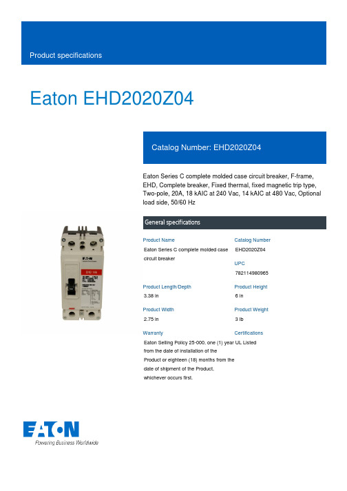
Eaton EHD2020Z04Eaton Series C complete molded case circuit breaker, F-frame, EHD, Complete breaker, Fixed thermal, fixed magnetic trip type, Two-pole, 20A, 18 kAIC at 240 Vac, 14 kAIC at 480 Vac, Optional load side, 50/60 HzGeneral specificationsEaton Series C complete molded case circuit breakerEHD2020Z047821149809653.38 in 6 in2.75 in 3 lb Eaton Selling Policy 25-000, one (1) year from the date of installation of the Product or eighteen (18) months from the date of shipment of the Product, whichever occurs first.UL Listed Product NameCatalog Number UPCProduct Length/Depth Product Height Product Width Product Weight WarrantyCertificationsSeries C18 kAIC at 240 Vac14 kAIC at 480 VacFEHD50/60 HzComplete breakerOptional load side20 AFixed thermal, fixed magnetic Two-pole UL listed 100%-rated molded case circuit breakersApplication of Tap Rules to Molded Case Breaker Terminals Application of Multi-Wire Terminals for Molded Case Circuit BreakersStrandAble terminals product aidCurrent limiting Series C molded case circuit breakers product aidMotor protection circuit breakers product aidPower metering and monitoring with Modbus RTU product aidCircuit breaker motor operators product aidMOEM MCCB Product Selection GuidePlug-in adapters for molded case circuit breakers product aidMulti-wire lugs product aidCounterfeit and Gray Market Awareness GuideBreaker service centersMolded case circuit breakers catalogEaton's Volume 4—Circuit ProtectionTime Current Curves for Series C® F-Frame Circuit BreakersInstallation Instructions for EHD, EDB, EDS, ED, EDH, EDC, FDB, FD, HFD, FDC, HFDDC Circuit Breakers and Molded Case SwitchesCircuit breakers explainedCircuit Breakers ExplainedSeries C G-Frame molded case circuit breakers time current curves MOEM MCCB product selection guideEaton Specification Sheet - EHD2020Z04Series C J-Frame molded case circuit breakers time current curves Series C F-Frame molded case circuit breakersSeriesInterrupt ratingFrameCircuit breaker type Frequency ratingCircuit breaker frame type TerminalsAmperage RatingTrip TypeNumber of poles Application notesBrochuresCatalogsDrawingsInstallation instructions MultimediaSpecifications and datasheetsEaton Corporation plc Eaton House30 Pembroke Road Dublin 4, Ireland © 2023 Eaton. All Rights Reserved. Eaton is a registered trademark.All other trademarks areproperty of their respectiveowners./socialmedia。
- 1、下载文档前请自行甄别文档内容的完整性,平台不提供额外的编辑、内容补充、找答案等附加服务。
- 2、"仅部分预览"的文档,不可在线预览部分如存在完整性等问题,可反馈申请退款(可完整预览的文档不适用该条件!)。
- 3、如文档侵犯您的权益,请联系客服反馈,我们会尽快为您处理(人工客服工作时间:9:00-18:30)。
Railway application Basic coordination part 1:
Basic requirements : Clearances and creepage distances for all electrical & electronic equipment
3/ Electron flow through material EN 50124 scope = 1/ + 2/ only Protection against electric shocks
18/01/2013 TECTRAIN Mai 2004 Erick Pauchet 2
Creepage & Clearance Links with usable standards
18/01/2013 TECTRAIN Mai 2004 Erick Pauchet 6
CREEPAGE & CLEARANCE Pollution Degree
Paragraph 2.5 - Table A4 :
PD1 Dust deposit no pollution non conductive well protected protected non conductive temporary conductivity low conductivity low conductivity Occasionally conductive with periodic cleaning Occasionally conductive coming from heavy pollution Humidity Dry no condensation
PD4B
Occasionally conductive Rain, snow, ice, fog TECTRAIN Mai 2004 Erick Pauchet coming from very heavy polluLEARANCE Comparative Tracking Index (Material characteristic)
Supplementary insulation : An independent insulation applied in addition to basic insulation in order to provide protection against electric shock in the event of failure of the basic insulation. Example : Fuse, ground connection … Double insulation = Basic insulation + Supplementary insulation Symbol =
Pollution Degree PD
Rated Voltage UNm Over voltage Category OV Rated Impulse Voltage UNi
Nominal Voltage UN
Comparative Tracking Index CTI
Distances Cp - Cr
=>for railway power distribution
Nominal Voltage Un Power supply According to EN 50163 dc (kV) dc (kV) Minimum values of the rated insulation Voltage Unm Rolling stock kV Fixed installation kV
Paragraph 2.6.1.3 :
Material group I II IIIa IIIb CTI 600<CTI 400<CTI<600 175<CTI<400 100<CTI<175 Class Class 1A4.5 Class 1A3.5 Class 1A2.5 Class 1A0
Over voltage Category (application)
Paragraph 6.3.1.1 :
OV1 : OV2 : OV3 : OV4 :
18/01/2013
circuits which are protected against external & internal over voltages and which only very low voltage can occur. The same as OV1, but with harsher over voltage condition and-or higher requirement concerning safety and reliability The same as OV4, but with less harsh over voltage condition and-or lower requirement concerning safety and reliability Circuits which are not protected against external or internal over voltages.
TECTRAIN Mai 2004 Erick Pauchet 8
CREEPAGE & CLEARANCE UNm : Rated voltage
Data supplied by customer or Correlation between Un and UNm
Table D1- Annex D :
18/01/2013
TECTRAIN Mai 2004 Erick Pauchet
5
CREEPAGE & CLEARANCE Insulation definition
Basic insulation : The insulation applied to live part to provide basic protection against electric shocks .
Application Voltage Voltage Voltage
Rated Voltage UNm Nominal Voltage UN
Battery supply kV
0.6 0.75 1.5 18/01/2013
0.72 0.9 1.8 TECTRAIN Mai 2004 Erick Pauchet
18/01/2013 TECTRAIN Mai 2004 Erick Pauchet 1
EN 50124 scope The 3 insulation failure modes
High Voltage
1/ Electron flow in air : Clearance
Ground
2/ Electron flow on material surface : Creepage
18/01/2013
TECTRAIN Mai 2004 Erick Pauchet
4
CREEPAGE & CLEARANCE Voltage definition
Nominal Voltage Un : A suitable approximate voltage value used to designate a given supply system
CE Field: Electrical Equipment (75 Vdc/1500 Vdc) measurement
CE Marking (Safety)
Application standard
Mains Standards
LVD 73/23 EN 61010
EN 50178
EN 50155
Others
Creepage & Clearance parameters
High Voltage
Clearance Creepage
Ground
APPLICATION Environment (Humidity) Safety level
Single or Double Insulation
PRODUCT Voltage Voltage Material Shape
•Creepage •Clearance
6.7
Creepage & clearance
5.2.16
Safety Requirements
EN 50124
Equivalent results (Unified standards)
18/01/2013 TECTRAIN Mai 2004 Erick Pauchet 3
0.72 0.9 1.8 9
CREEPAGE & CLEARANCE UNi Rated Impulse Voltage
Rated Voltage UNm
Paragraph 2.2 :
Method 1 : =>Table A2 or A1 Method 2 : => Refer standard
OV
PD2
Rare, short Temporary condensation
PD3 PD3A PD4
Frequent condensation damp, long time condensation Rain, snow, ice, fog
PD4A
Rain, snow, ice, fog
18/01/2013
Requested between end user and the system.
Reinforced insulation : A single insulation system applied to live parts, wich provides a degree of protection against electric shock equivalent to double protection.