液位控制系统论文中英文资料对照外文翻译
中英文翻译(中)
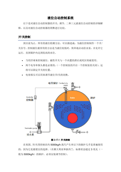
液位自动控制系统以下是对液位自动控制器的开关,调节,二和三元素液位自动控制的详细解释,以及对液位自动控制器的利弊进行比较。
到目前为止,所有的液位检测方法,可以描述成:为液位控制制作一个开/关信号。
控制液位最常用的方法是当液位较低时,简单地启动给水泵,并允许它运行,直到锅炉内达到较高的水位。
∙当用浮球来控制液位,磁性开关与一个内置的滞后或死区将被使用。
∙两个电导率探头都是必要的,(一个控制泵的开启一个控制泵的关闭),这将可以固定开关的位置。
∙电容探头可以用来调节液位开/关的切换。
图3.17.1 开/关控制在英国,开/关型控制在约5000kg/h蒸汽产生率以下的锅炉几乎是普遍使用的,因为它是最便宜的选择。
(在澳大利亚和新西兰,标准状态超过3兆瓦(一般为5000kg/h)的锅炉,必须安装调节控制)。
然而,我们可以说,用这种类型的开/关对锅炉控制是不理想的,因为当泵正在降低锅炉的压力时,要有相对较高温度的“冷”给水流量。
这将导致燃烧器的发射率不断随泵的切换而关闭。
举一个典型的例子,通过计算表明,即使在80℃的时候给水,燃烧器的发射率可能要比关闭水泵时高出40%。
这种连续变化会导致:∙磨损燃烧控制器∙锅炉的温度不断循环∙降低工作效率∙如题3.17.2所示,是对一个“锯齿”型蒸汽流量图的记录与描绘。
图3.17.2锯齿TRACEON图表记录如果蒸汽负荷高,可变的蒸汽流量,往往会增加水与蒸汽的凝结转换速度,将使液位与相关联的危险低水位锁定越来越不稳定,特别是在多个锅炉安装在一起的时候。
然而,事实上,开/关控制仍然非常广泛的运用于中小型锅炉中,如上述所说的,蒸汽锅炉运行在与负载大波动相关的许多问题中,有一部分是与开/关液位控制系统有关的。
优点:∙简单∙廉价∙对锅炉有很好的支撑缺点:∙每台锅炉都需要有自己的给水泵∙给水泵及控制装置有更多的磨损∙蒸汽压力和流量会变化∙更多的锅炉水被转换凝结∙在日常工作运行中,有较高的大负荷波动的可能性在这种类型的系统中,给水泵连续运行,自动阀门(给水泵和锅炉之间)控制给水流量,并与蒸汽需求相匹配。
外文文献及翻译:基于matlab╲╲dde╲╲simulink╲╲力控的液位控制系统
外文翻译The liquid level control system based ondde\matlab\simulinkProcess control is an important application field of automatic technology, it is to point to the level, temperature, flow control process variables, such as in metallurgy, machinery, chemical, electric power, etc can be widely used. Especially liquid level control technology in real life, played an important role in production, for example, the water supply, civil water tower if low water levels, can affect people's lives in water; Industrial enterprises with water, if the drainage water drainage or controlled properly or not, in relation to the workshop of condition; Boiler drum, if the control level boiler is too low, can make level boiler overheating, possible accident; Jing flow, liquid level control tower control accuracy and level of the craft can influence the quality of the products and the cost, etc. In these production field, are basically labor strength or the operation has certain risk nature of work, extremely prone to accidents caused by operating error, the losses, killing manufacturer. Visible, in actual production, liquid level control accuracy and control effects directly affect the factory production cost and economic benefit of safety coefficient. Even equipment So, in order to ensure safety, convenient operation, you have to research the development of a d v a n c e d l e v e l c o n t r o l m e t h o d s a n d s t r a t e g i e s.The graduation design topic is the liquid level control system based on dde\matlab\simulink\force control, Among them was controlled object for tank level, Communication mode for DDE communications , Matlab is mainly used in the simulation test ,And force control software used for modeling, This system mainly through combination of hardware and software device to achieve precise control of liquid level , In modern industry level control of important component, it influence upon production not allow to ignore, in order to ensure safety in production and the product quality and quantity, the level and perform effective control is very necessary, The following is a description of all aspects:一PID controllerA proportional–integral–derivative controller (PID controller) is a generic .control loop feedback mechanism widely used in industrial control systems.A PID controller attempts to correct the error between a measured process variable and a desired set point by calculating and then outputting a corrective action that can adjust the process accordingly.The PID controller calculation (algorithm) involves three separate parameters; the Proportional, the Integral and Derivative values. The Proportional value determines the reaction to the current error, the Integral determines the reaction based on the sum of recent errors and the Derivative determines the reaction to the rate at which the error has been changing. The weighted sum of these three actions is used to adjust the process via a control element such as the position of a control valve or the power supply of a heating element. By "tuning" the three constants in the PID controller algorithm the PID can provide control action designed for specific process requirements. The response of the controller can be described in terms of the responsiveness of the controller to an error, the degree to which the controller overshoots the set point and the degree of system oscillation. Note that the use of the PID algorithm for control does not guarantee optimal control of the system or system stability.Some applications may require using only one or two modes to provide the appropriate system control. This is achieved by setting the gain of undesired control outputs to zero. A PID controller will be called a PI, PD, P or I controller in the absence of the respective control actions. PI controllers are particularly common, since derivative action is very sensitive to measurement noise, and the absence of an integral value may prevent the system from reaching its target value due to the control action.1.Control loop basicsA familiar example of a control loop is the action taken to keep one's shower water at the ideal temperature, which typically involves the mixing of two process streams, cold and hot water. The person feels the water to estimate its temperature. Based on this measurement they perform a control action: use the cold water tap to adjust the process. The person would repeat this input-output control loop, adjusting the hot water flow until the process temperature stabilized at the desired value.Feeling the water temperature is taking a measurement of the process value or process variable (PV). The desired temperature is called the set point (SP). The outputfrom the controller and input to the process (the tap position) is called the manipulated variable (MV). The difference between the measurement and the set point is the error (e), too hot or too cold and by how much. As a controller, one decides roughly how much to change the tap position (MV) after one determines the temperature (PV), and therefore the error. This first estimate is the equivalent of the proportional action of a PID controller. The integral action of a PID controller can be thought of as gradually adjusting the temperature when it is almost right. Derivative action can be thought of as noticing the water temperature is getting hotter or colder, and how fast, and taking that into account when deciding how to adjust the tap,Making a change that is too large when the error is small is equivalent to a high gain controller and will lead to overshoot. If the controller were to repeatedly make changes that were too large and repeatedly overshoot the target, this control loop would be termed unstable and the output would oscillate around the set point in either a constant, growing, or decaying sinusoid. A human would not do this because we are adaptive controllers, learning from the process history, but PID controllers do not have the ability to learn and must be set up correctly. Selecting the correct gains for effective control is known as tuning the controller.If a controller starts from a stable state at zero error (PV = SP), then further changes by the controller will be in response to changes in other measured or unmeasured inputs to the process that impact on the process, and hence on the PV. Variables that impact on the process other than the MV are known as disturbances and generally controllers are used to reject disturbances and/or implement set point changes. Changes in feed water temperature constitute a disturbance to the shower process.In theory, a controller can be used to control any process which has a measurable output (PV), a known ideal value for that output (SP) and an input to the process (MV) that will affect the relevant PV. Controllers are used in industry to regulate temperature, pressure, flow rate, chemical composition, speed and practically every other variable for which a measurement exists. Automobile cruise control is an example of a process which utilizes automated control.Due to their long history, simplicity, well grounded theory and simple setup and maintenance requirements, PID controllers are the controllers of choice for many of these applications.2.PID controller theoryNote: This section describes the ideal parallel or non-interacting form of the PID controller. For other forms please see the Section "Alternative notation and PID forms".The PID control scheme is named after its three correcting terms, whose sum constitutes the manipulated variable (MV). Hence:where Pout, Iout, and Dout are the contributions to the output from the PID controller from each of the three terms, as defined below.2.1. Proportional termThe proportional term makes a change to the output that is proportional to the current error value. The proportional response can be adjusted by multiplying the error by a constant Kp, called the proportional gain.The proportional term is given by:WherePout: Proportional outputKp: Proportional Gain, a tuning parametere: Error = SP − PVt: Time or instantaneous time (the present)Change of response for varying KpA high proportional gain results in a large change in the output for a given change in the error. If the proportional gain is too high, the system can become unstable (See the section on Loop Tuning). In contrast, a small gain results in a small output response to a large input error, and a less responsive (or sensitive) controller. If the proportional gain is too low, the control action may be too small when responding to system disturbances.In the absence of disturbances, pure proportional control will not settle at its target value, but will retain a steady state error that is a function of the proportional gain and the process gain. Despite the steady-state offset, both tuning theory and industrial practice indicate that it is the proportional term that should contribute the bulk of the output change.2.2.Integral termThe contribution from the integral term is proportional to both the magnitude of the error and the duration of the error. Summing the instantaneous error over time(integrating the error) gives the accumulated offset that should have been corrected previously. The accumulated error is then multiplied by the integral gain and added to the controller output. The magnitude of the contribution of the integral term to the overall control action is determined by the integral gain, Ki.The integral term is given by:Iout: Integral outputKi: Integral Gain, a tuning parametere: Error = SP − PVτ: Time in the past contributing to the integral responseThe integral term (when added to the proportional term) accelerates the movement of the process towards set point and eliminates the residual steady-state error that occurs with a proportional only controller. However, since the integral term is responding to accumulated errors from the past, it can cause the present value to overshoot the set point value (cross over the set point and then create a deviation in the other direction). For further notes regarding integral gain tuning and controller stability, see the section on loop tuning.2.3 Derivative termThe rate of change of the process error is calculated by determining the slope of the error over time (i.e. its first derivative with respect to time) and multiplying this rate of change by the derivative gain Kd. The magnitude of the contribution of the derivative term to the overall control action is termed the derivative gain, Kd.The derivative term is given by:Dout: Derivative outputKd: Derivative Gain, a tuning parametere: Error = SP − PVt: Time or instantaneous time (the present)The derivative term slows the rate of change of the controller output and this effect is most noticeable close to the controller setpoint. Hence, derivative control is used to reduce the magnitude of the overshoot produced by the integral component and improve the combined controller-process stability. However, differentiation of asignal amplifies noise and thus this term in the controller is highly sensitive to noise in the error term, and can cause a process to become unstable if the noise and the derivative gain are sufficiently large.2.4 SummaryThe output from the three terms, the proportional, the integral and the derivative terms are summed to calculate the output of the PID controller. Defining u(t) as the controller output, the final form of the PID algorithm is:and the tuning parameters areKp: Proportional Gain - Larger Kp typically means faster response since thelarger the error, the larger the Proportional term compensation. An excessively large proportional gain will lead to process instability and oscillation.Ki: Integral Gain - Larger Ki implies steady state errors are eliminated quicker. The trade-off is larger overshoot: any negative error integrated during transient response must be integrated away by positive error before we reach steady state.Kd: Derivative Gain - Larger Kd decreases overshoot, but slows down transient response and may lead to instability due to signal noise amplification in the differentiation of the error.二Matlab IntroductionThe MATLAB® environment is well suited to rapid prototyping and application development. The interactive programming environment, built-in math functions, toolboxes, editing and debugging tools, and deployment options all contribute to reducing your overall development time.By using the built-in math functions and the many specialized functions contained within our toolboxes, MATLAB can significantly reduce the time it takes you to develop prototypes. In addition to integrated editing and debugging tools, MATLAB provides a performance profiler to help you further optimize your code when programming in MATLAB.Building applications around complex algorithms and graphics is easier than ever with the GUI builder, GUIDE. GUIDE was redesigned in MATLAB 6 to save you time. It offers all the drag and drop interface options you would expect, such as textboxes, radio buttons, check boxes, listboxes, sliders, pop-up menus, frames and more.When you're ready to deploy your application, the MathWorks offers a number of different options that allow you to either convert or interface your MATLAB application to other environments including C/C++ and the Web. MATLAB is the most productive development environment for creating scientific and engineering applications because it offers powerful tools for every step in the process to reduce your overall development time.MATLAB is a high-performance language for technical computing. It integrates computation, visualization, and programming in an easy-to-use environment where problems and solutions are expressed in familiar mathematical notation. Typical uses include• Math and computation• Algorithm development• Data acquisition• Modeling, simulation, and prototyping• Data analysis, exploration, and visualization• Scientific and engineering graphics• Application development, including graphical user interface building三DDE IntroductionDynamic data exchange (DDE, Dynamic data exchange) is real-time exchange data between applications, it is the effective method between different applications to share data a agreement. DDE agreement is a kind of open, and language unrelated, based on protocol, it allows multiple applications to any human agreed format data exchange or command. It is application through Shared memory process of the communication between a form, also need not user intervention of good data exchange method.DDE applications can be divided into four types: client and server and client/server and the monitor. Conversation is a basic concept of DDE. DDE conversation happened in client applications and server application between. Customer is responsible for initializing and attendant session and control conversation flow, from the server application request data or services; The server application response client applications of data or service request. Client/server applications is both client applications and server application request, it can be and can provideinformation. Monitor application for debugging purposes. DDE applications can have multiple burst conversation, a service applications can also have multiple client applications, a client applications can to multiple requests data service applications, and an application can also act as client applications and services applications, when don't need the service application data or service, the customer will terminate session. DDE agreement must be synchronous control the news session, but in different application can switch between asynchronous session.DDE Application using the three layer identification system: Application name apply), theme name (from) and project name (Item). Application name (also called service name) is located at the top of the hierarchical structure, the service application registration for pointed out that particular DDE server application name, customer the application wants to establish session with the server application must be specified application name when this string marks; Name in every conversation topics is one and to identify logical data connection string, is the total classification, data it defines a server application conversation theme content, the server application can support one or more theme name; Project name identifies exchange unit of data string, furthermore confirm the conversation of detailed information, every theme name may have one or more project name. Example: for a database interface applications, will it supports database name as a theme name, and will all sorts of SQL commands as project name, because the server application can support one or more theme, and each theme name name may have one or more project name; So, when to change or reconstruct a conversation, just changing the subject name or project name can.四force control IntroductionForce control is Beijing SANWEI force control technology and "soft" control strategy software, real-time database and its management system, Web portal of tools and other products. These products are not isolated, and the force control is an application scale can free the system structure, the whole expansion force control system and its various products are made from some components procedures according to certain combinations and become. So this guide is not specifically targeted specific products separately describes the use of method, but the common use of all products introduced method. Force control configuration software is a can run on Windows 98/2000 / NT environment, and can run on Windows CE, DOS embedded environment control fu- nctions such as software modules. It USES function diagram way for users provide interface, possess and real-time database, graphical interface system and communication function.Force charged with monitoring configuration software is to the field production data acquisition and process control of specialized software, the biggest characteristic is to flexible "configuration mode" instead of programming approach to system integration, and it provides a good user interface and simple engineering development, as long as the realization method of software module of pre-settings simple "configuration", it can easily realization and complete monitoring layer each function, shorten the automation engineer system integration time, greatly improve the efficiency of integration.Force charged with monitoring configuration software is in the automatic control system monitoring layer level software platform, it can also and the domestic and foreign various industrial control network communication equipment manufacturer, it is ok with high reliable industrial controlling computer and network system integration, can achieve the purpose of the centralized management and monitoring, and can also be convenient to control layer and management for software and hardware to implement all the interface, with "third party" hardware and software systems for integration.The control strategy in the force control, an application in generator may have a lot of control strategy, but only one main strategy. The Lord, the Lord was first execution strategy calls. Other strategies strategy Strategy nested grade 4, namely for most 0 ~ 3 level, in this category 4, grade 3 0 level supreme, the lowest. Senior strategy can call low-level strategy, and low-level strategy can't call senior strategy. In addition to tier 3 most can have 127 strategy outside, other three grades maximum respectively are 255 strategy. Control strategy of by some basic function blocks, a function blocks represent an operation, algorithm or variables. Function blocks basic execution element is strategy, similar to an integrated circuit blocks, have several input and output, each input and output tube feet all have the only name.Force control control strategy is in control strategy, edited generated generators in automatic control strategy for strategies when inventory compiled, and check grammar mistakes, compile can also manually. Control strategy, and you can also call between if A strategy was B strategy calls, says A is B son strategy. A functional block can be repeated calls, each calls are automa- tically entitled to a name by. The executive order and function block in the position of screen on the upper left, position relevant function block, according to priority execution left after the first order under implementation.Force control control strategy of basic function blocks generator was divided into five categories: variable function blocks, mathematical operation function blocks, program control function blocks, logic function blocks function block and control algorithm.基于matlab\dde\simulink\力控的液位控制系统过程控制是自动技术的重要应用领域,它是指对液位、温度、流量等过程变量进行控制,在冶金、机械、化工、电力等方面得到了广泛应用。
液位控制论文
液位自动控制论文:班级:专业:学号:液位自动控制系统摘要:本文从液位传感器构成原理的分析出发,详细研究了液位继电器在给排水自动控制中的典型应用,并对液位继电器的技术性能进行了量化分析,从理论上推导出各种不同水质情况下,液位继电器测量(检测)适用的距离范围。
关键词:液位检测;给排水;自动控制中图分类号:文献标识码:文章编号:For Draining Water Automatic Control Application Research Sun Ping、Lin Chenfei、Chen Guolei、Lin Yahong、Fang Liya (Zhejiang Water conservancy and Hydropower College,Hangzhou 310018 China)Abstract:This article embarks from the fluid position sensor constitution principle analysis,gives deep insight into the typical application of fluid position relay in the draining water automatic control. It carries on a quantification analysis of the fluid position relay technical performance,theoretically infers the suitable distance scope of fluid position relay measurement (examination) in each different water quality situation.Key words: Fluid position examination, For draining water, Automatic control供水和排水的液位自动控制的方法很多,从控制思想讨论,有开关量的动态液位控制和模拟量的恒值液位控制,前者是将液位控制在一定的变化范围内,后者是用PID调节算法,将液位始终保持几乎恒定状态。
基于单片机的水位控制系统外文翻译

译文:水位检测设计中国水之源总量居世界第六位,人均占有水资源量仅为世界人均占有量旳四分之一,并且在地区上分布很不平衡,长江以北旳广大地区,尤其是北方大、中都市大部分地区处在缺水状态,水资源短缺已成为制约我国经济发展旳一种重要原因。
合理旳运用水资源已成为我国目前面临旳一种重要问题。
为了到达水资源旳合理运用,除了要在兴修水利工程和提高全民节水意识等方面努力提高。
而更重要旳是应用新旳技术信息,实时精确旳理解和掌握多种水情信息,以此根据做出对旳旳水资源调度和管理,做到防患于未然,尽量减少水资源旳挥霍。
再加上长期以来水情水位测量一直是水文、水利部门旳重要课题。
为及时发现事故苗头,防患于未来,经济实用、可靠旳水位无线监测系统将会发挥巨大旳作用。
水位是水库大坝安全、水利排灌调度、蓄水、泄洪旳重要参数之一。
水位旳自动化监测、传播和处理为水库现代化建设提供了良好旳基础资料。
在工农业生产旳许多领域都需要对水位进行监控。
在现场也许无法靠近或无需人力来监控时,我们就可以通过远程监控,坐在监控室里对着有关旳仪器就能对现场进行监控,既以便又节省人力。
为了保证水利发电站旳安全生产,提高发电效率,水电站生产过程需要对水库水位、拦污栅压差和尾水位进行监测。
不过,由于不一样电站有着不一样旳实际状况,因此就有着不一样旳技术规定,并且水位参数旳测量措施和测量位置不一样,对监测设备旳规定亦有所不一样。
这样往往导致监测系统设备专用化程度高,品种多,互换性差,不利于设备维护,亦增长了设备设计、生产、安装旳复杂性。
因此,在综合研究水电站水位监测旳实际状况以及特点旳基础上,运用现代电子技术,尤其是单片机技术和不挥发存储器技术,设计开发一种通用性好,可靠性高,维护以便,可合用于多种监测环境旳多模式水位自动监测系统具有重要旳实际意义。
本课题根据水库旳水位测量需要,设计远程单片机水位监测系统,系统具有水位旳自动检测、定期处理、数据GPRS远程上传等功能。
外文翻译---水塔水位控制系统的研究与设计
外文翻译---水塔水位控制系统的研究与设计外文资料翻译Water Tower Water Level Control System Research And DesignAbstract: The water tower is a water level control system for residential quarters of China's extensive use of the water supply system, the existence of the traditional control methods to control the accuracy of the low power consumption of the shortcomings of large, research-based PLC controlled multi-pump cycle frequency constant pressure water supply system, using programmable logic controller, inverter, as well as devices such as pressure transmitter, complete logic control, speed control and data sampling frequency and other functions, allowing the system to achieve automatic control, to achieve the purpose of energy conservation, improve the quality of the water supply system.Key words: PLC, inverter,constant pressure water supply0 IntroductionWater tower water level control system is the wider use of residential quarters of China's water supply system, water supply systems in most of the traditional use of water towers, water tanks, or high pressure tank pressurization equipment to pump water higher than the actual height of the head to "upgrade" of water, the the result of increased water pump shaft power and energy consumption. Research and design of the towers is the water level control system uses a [1] constant pressure water supply system, stepless speed pumps. Automatically based on changes in water-conditioning system operating parameters to maintain a constant pressure to meet the water requirements of today's advanced, energy-saving and reasonable water supply system [1]. Pump started, pid controller pressure transmitter to the control point to provide the pressure signal, when the pressure point is not equal to set value, pid controller by adjusting the inverter output frequency to change the pump speed to regulate the pipeline pressure constitutes a closed-loop feedback control system, water pressure regulator so that users timely, small fluctuations in results. And in the process control system designed to take full account of the principle of load balancing, to take "first-in-first out" strategy of lining up, the way the implementation of the rotating frequency to ensure that the basic balance of the water usage.1 Frequency Control Constant Pressure Water SupplyPrincipleFrequency Control Constant Pressure Water Supply System by the programmable logic controller (plc), converter (built-pid), pressure transmitter, low-voltage electrical and pump components, such as Figure1. Map m1 ~ m3 for water pump motors, p1 ~ p3 for pumps, km1 ~ km6 for motor starting and stopping each of the AC contactor switch. Basic working principle of the system: by the plc a signal to the inverter to control the water cycle work, when the large volume of water consumed by the plc control of all water line installed in the outlet pipe of the pressure transmitter, pressure standard signals into dc 0 v ~ 10 v into the analog signal converter with pid regulator, pressure settings and pressure feedback values after the implementation of pid calculated values of the output of a frequency converter to set the value for the pump by the inverter to provide variable frequency electrical power to realize stepless speed regulation of electric pumps to regulate the exit of the water supply pipe network pressure, constant pressure water supply to achieve the purpose. Pressure feedback signal in order to ensure an accurate value, yet the value of feedback signal to set the filter time constant. The scope of the power converter, Figure 1 can increase the number of the motor to achieve "a multi-trailers," Optimization of the program.2 towers of water level control system designFrequency according to the principle of constant pressure water supply system the design water level control system of the water tower block diagram shown in Figure 2, the city water network eq with the water level controller to control the injection valve yv1, as long as the water level below the high water mark, then to the pool water automatically. Pool of high / low water level signal directly to the plc, as a high / low level alarm. In order to ensure continuity of supply, the water level of the smaller distance between the upper and lower limits. Domestic water and fire water pump three shared [3], usually yv2 solenoid valve in a state of loss, the closure of the fire pipe network, when a fire occurs, the solenoid valve was yv2 electricity, water distribution network with the closure of life, three water pumps for fire use, and maintain high-pressure fire water value. After the lifting of the fire, three use domestic water pump replaced and the cycle of operation, to maintain constant low water value. Each pump motor can run frequency, and frequency can be run. When the small volume of water consumed, a water pump under the control of the converter stable operation of large quantities of water to the pump when running at full speed there is no guarantee that the pressure on network stability, plc pressure given the lower limit of the inverter signal and high-speed signal at the same time plc was detected, plc automatically work in the original state of the pump frequency into frequency operation, in order to maintain the continuity of pressure at the same time use the next pump put into operation after start-up converter in order to increase the supply pipe network pressure of water to ensure stability; if running two pumps can not meet the requirements of the pressure, the frequency of work will be followed by a state into the pump-frequency operation, and then pump into a variable frequency operation; when the water consumption reduction, the first performanceinverter has been working effectively at the lowest speed signals, when the pressure signal, such as the ceiling is still there, plc will be the first first run of the pump frequency to quit in order to reduce the volume of water supplied, when the two signals when there are still, plc and then quit second frequency of the pump to run until a constant pressure water supply pump with frequency converter. All pump motors start from a stop to and from the start to stop by the inverter to control to achieve soft-start with set, to avoid the start of high-current impact to the pump motor to extend the life of the motor. At the same time, the use of variable frequency operation of the system pumps water cycle in order to "first to open the first gate" of the order of related pumps, so that both the water supply system to ensure back-up water pumps, water pumps and the system have the same running time as effective in preventing back-up pump death occurred not long-term phenomenon of rust and improve the comprehensive utilization rate of equipment, reducing maintenance costs.Electrical control system main circuit see Figure 3. AC contactor km1, km3, km5 were three pump motor control m1, m2, m3 frequency operation; AC contactor km2, km4, km6 respectively control m1, m2, m3 of Frequency operation; fr1, fr2, fr3 thermal relay for protection of the three pump motor overload; qs1, qs2, qs3, qs4 respectively, and three pump motor inverter main circuit isolation switch; fu1 ~ fu3 mainly The fuse circuit. The system works in manual mode, plc alarm detection only by the artificial adoption of panel buttons and switches From water pumps to stop and switch; the system works in automatic mode, all controlled by the plc completed report to the police.3 towers of water level control system software designThe main function of the automatic control system is achieved through software in light of the foregoing [1] control constant pressure water supply system requirements, water towers of the main process control system shown in Figure 4. Use of the timer interrupt function of the realization of pid control regular sampling and output control, three pumps to generate switching signals, the signal contacts of the integrated logic control and alarm handling by the program. In program design to take full account of the principle of load balancing, to take "first-in-first out" strategy of lining up, the way the implementation of the rotating frequency to ensure that the basic balance of the water usage. Constant pressure of life and fire of the two pairs of constant digital value is used directly in the proceedings set. Life when the water supply system for the full-scale settings of 70%, when the fire water supply system for the full-scale settings of 90%. Pid loop gain and time constant is initially set at: gain kc = 0.25, sampling time ts = 0.2 s, integration time ti = 30 min. in accordance with specific conditions need to be further adjusted in order to achieve optimal control.To a constant water supply, landing in the water pressure to increase the inverter output frequency, when the maximum frequency converter and a constant pressure pump can not meet the requirements, while running the pump frequency to switch to the running frequency, At the same time need to start asecond frequency or third pump until the water supply to meet the requirements. Need to determine criteria for the launch of a new water pump is the inverter output frequency is set to reach the upper limit. In order to determine the frequency of the inverter limits the accuracy of least squares by chance should be the frequency of the frequency of fluctuations in the ceiling from the situation. Inverter control motor pumps are activated each time the soft-start, and requires the use of water pumps must turn to serve as a continuous variable frequency pump operation shall not exceed 3 h, each time when the need to launch a new water pump, the pump will run from the existing removal of the inverter, and replace the power-frequency operation, reset the inverter and run the pump for a new start. Three pumps to control the duty cycle is the use of pump No. 1 way to achieve (to 3 in the plus 1 equal to zero), or combined with the total number of pump pump pump rotation to achieve its work.4 Concluding remarksIn this paper, the design of the towers the water level control system uses a programmable logic controller, inverter based on changes in water pressure transmitter through the pid to realize stepless speed variable frequency drive pump motor in the water changes to maintain constant water pressure meet the water requirements, so as to achieve the purpose of constant pressure water supply. In the process control system designed to take full account of the principle of load balancing, to take "first-in-first out" strategy of lining up, the way the implementation of the rotating frequency to ensure that the basic balance of the water usage. Frequency Constant Pressure Water Supply to change the supply of the previous quantitative methods to achieve "DAMA" principle, constant pressure water supply frequency mode thus saving energy, easy to operate, high degree of automation.水塔水位控制系统的研究与设计摘要:水塔水位控制系统是我国住宅小区广泛应用的供水系统,传统的控制方式存在控制精度低、能耗大的缺点,研究设计的基于PLC控制的多泵循环变频恒压供水系统,采用可编程序控制器、变频器以及压力变送器等器件,完成逻辑控制、变频调速和数据采样等功能,使系统实现自动控制,达到节能的目的,提高了供水系统的质量。
毕业设计论文液位控制系统

毕业设计论文液位控制系统Newly compiled on November 23, 2020毕业设计基于S7-300的单容水箱液位控制系统设计Design of Liquid-Level Control System Based on S7-300 专业班级:自动化0x0x班学生姓名: x x x指导教师: x x x 副教授学院:自动化与电气工程学院2016年 6月摘要可编程逻辑控制器(PLC)作为现代工业自动化的三大支柱之一,以其可靠性、灵活性在工业控制领域得到了迅猛的发展。
PLC是微电子技术和自动控制技术相结合的产物,并受到计算机技术、通信技术的影响。
我国近年来工业自动化水平逐渐提高,PLC在许多行业得到了越来越广泛的应用。
西门子公司的S7-300系列PLC以结构紧凑,扩展能力强,高性价比的特点在许多行业受到青睐。
在本次设计中,就以S7-300作为控制器,设计一个运行稳定、安全可靠又经济的液位控制系统。
控制核心以S7-300系列的CPU313C-2DP为主,以电磁阀、压力变送器、水泵、上位机、分隔式水槽等为辅构成了单容水箱液位控制系统,对整个液位控制系统进行了硬件设计和软件设计。
在设计过程中,首先,进行硬件的选择、设计。
其次,针对S7-300PLC的进行模块化编程,实现数据的归一化等功能。
最后,利用组态王软件设计人机对话界面,通过上位机控制实现液位的自动控制,上下限参数的在线设置,及液位测量值的在线监控;达到液位控制系统的技术要求。
关键词:S7-300;组态王;液位控制ABSTRACTProgrammable Logic Controller (PLC), one of the three pillars of modern industry automation, has gained rapidly development at the industry control field for its high reliability and flexibility. PLC is the product of the combination of microelectronic technology and automatic control technology, and it can be influenced by computer technology and communication technology. Recent years, as the level of the industry automation increased in our country, PLC has been widely used in more and more fields. Siemens PLC of the s7-300 series has been the favor of many industries, with the characters of compacted structure, strong extensible ability, and high function/price ratio.This design is going to fulfill a liquid level control system, which is stable, safe, and affordable, using s7-300 as the controller. The core is CPU313C-2DP of S7-300 series and the auxiliary parts contain a solenoid valve, a pressure transmitter, a motor, PC, a separated-type tank and so on. In the design, software system and hardware system can be designed completely.During the designing process, first of all, hardwires are chosen and designed. Second, module programming can be done to get normalized data and Position Control. Third, HMI can be finished using King software, which is used to control the liquid level, adjust the top and bottom limitation parameters on-line, monitor measured value of the liquid level, and meet the technical needs of controlling liquid level.Key Word: S7-300;Kingview;Liquid level目录1 引言课题的提出过程控制通常是指连续生产过程的自动控制,是自动化技术最重要的组成部分之一。
液位自动控制系统的研究_毕业设计论文1 推荐
液位自动控制系统的研究摘要水位控制系统设计是模拟工业生产过程中对水位、流量参数进行测量、控制、观察其变化特性,研究过程控制规律的课题,它主要研究过程控制中动态过程的一般特点——大惯性、大时延、非线性,难以对其进行精确控制,从而使其成为控制理论与控制工程、过程控制教学、试验和研究的理想对象。
本课题首先对水位控制系统做了整体的分析并简单介绍了水位控制系统的控制平台;然后详细介绍了PLC可编程控制器并详细分析了基于PLC的PID控制和串级PID控制,对串级控制系统的特点和主副回路设计进行了详述,设计了双容水箱串级水位控制系统,并根据4:1衰减曲线法对PID参数进行整定;最后根据理论分析进行水位控制系统实验,实验结果表明系统具有优良的控制精度和稳定性。
关键词:水位自动控制系统,PLC技术,PID控制,串级控制The Research of The Water Level Automatic Control SystemAbstractThe water level control system design is a topic, which allows study of the principles of process control as the process variables, for example the level and flux, to be measured, controlled and observed for its variability during the simulation process of modem industrial manufacture. It has the common characteristic of dynamic process in process control such as great inertia, larger delay, nonlinear and difficult to be controlled precisely, so that it becomes a perfect object in the field of control theory and control engineering, process control teaching, testing and study.This topic first has made the whole analysis to the water level control system and simply introduces the water level system control platform, then introduces the PLC programmable controller in detail and amply analyses the PID control and the cascade PID control which based on PLC.It introduces the cascade control system characteristic and the host vice-return route design in detail. The two-tank water level cascade control system has been designed. Then it carries on the PID parameter by 4:1 decay curve law; finally the water control system experiment has been done by the theoretical analysis.The experimental result indicates the system has the fine control precision and the stability.Key words: water level control system, PLC, PID control, cascade control目录摘要 (I)ABSTRACT (II)1 绪论 (1)1.1引言 (1)1.2水位控制当前的研究动态 (1)1.3PID调节器概述 (2)1.3.1PID控制特点 (2)1.3.2PID 控制中尚需解决的问题 (3)1.4本文的主要工作 (4)2 水位控制系统的整体分析 (5)2.1水位控制系统的整体设计 (5)2.2控制平台介绍 (5)2.2.1电源控制屏 (5)2.2.2交流变频调速器 (6)2.3被控对象介绍 (7)3 可编程序控制器PLC 概述 (8)3.1PLC的基本结构 (8)3.1.1 CPU 模块 (8)3.1.2 I/O 模块 (9)3.1.3 编程装置 (9)3.1.4电源 (10)3.2西门子S7-200PLC简介 (10)3.2.1 西门子 S7-200 PLC 的功能概述 (10)3.2.2 西门子 S7-200 PLC 的特点 (11)3.2.3 西门子 S7-200 PLC 的硬件结构 (11)3.2.4 西门子 S7-200 PLC 的工作原理 (12)3.3西门子S7-200PLC的编程语言 (14)3.4S TEP 7-M ICRO/WIN编程软件简介 (15)3.5西门子S7-200PLC的程序结构 (15)4 PID控制器的设计 (16)4.1PID算法概述 (16)4.2 串级控制系统 (18)4.2.1 串级控制系统的特点 (18)4.2.2 串级控制系统的设计 (19)4.3基于PLC的串级控制 (19)4.3.1控制系统框架 (19)4.3.2串级系统的参数整定 (21)5 控制结果 (22)5.1控制软件简介 (22)5.1.1控制界面 (22)5.1.2 控制软件的主要功能 (22)5.2实验结果及分析 (23)结束语 (26)致谢 (27)参考文献 (28)附录A(英文文献) (30)附录B(中文译文) (36)1 绪论1.1引言随着现代工业的进步,水位控制技术迅速发展,但与国外相比仍有很大的差距,当国内还在对水利采取笨拙的排水、泄水方式时,国外便开始通过先进的测控设备,对水利资源进行合理的疏导。
外文翻译---液位检测
附录CLiquidLevelMeasurementChemical industry with the progress of science and technology got rapid development, in order to make the equipment safe and reliable operation, and can be utmost to improve product quantity and quality, to effectively operate automatically and process adjustment, realize the scientific management for the enterprise to provide the necessary material and energy of accurate data, must be in production in the process of pressure, flow, level, temperature, chemical composition of various parameters such as timely, accurate measurement.Generally the process of containers, tanks, towers, tank of liquid surface position level, slot bucket, cans, and warehouse ChuFa solid block, the accumulation of particles, powder height and surface position is called a material level; Two not fluid boundary between the height and the liquid and solid separation height is called interface position, the position of assembly level, material level, liquid level interface.Material level measurement to correctly measure the container storage capacity or quality, know container level of high and low and adjust at any time, in the material level to maintain the required height.Material level measurement in chemical process, not only under normal temperature, atmospheric pressure and ordinary medium, material level, liquid level measurement of the interface, but also often meet high temperature, low temperature, high pressure, inflammable and explosive (negative temperature). Viscosity and foam, boiling dielectric material level measurement problems.In order to adapt to the characteristics of chemical objects, to meet the requirements of the chemical process material level measurement, there are many material level measurement and instrumentation.1. Ultrasonic liquid level meter and radar material level meter(1) ultrasonic liquid level meterMaterial level measurement process, the ultrasonic signal, issued by the ultrasonic probe, the liquid or solid material surface after launch back, by the same sensor receiving, ultrasonic measurement of the whole running time, so as to realize the measurement of material level,acoustic velocity transmission of the ultrasonic pulse, from transmitting to receiving to ultrasonic pulse need time interval and the transducer to the surface of the measured medium is proportional to the distance.Emit ultrasonic level meter pulse, not the echo of detection at the same time. Due to the launch of the ultrasonic pulse width has a certain time, and after launch the ultrasonic sensor and aftershocks, during cannot detect the echo, so from the start down the surface of the probe a short distance can't normal inspection, this distance is called blind spots. Was the highest level such as into the blind area, detect instrument will not be able to correctly, there will be error, if necessary, heightened level meter can be installed.Ultrasonic liquid level meter also has shortcomings, the ultrasonic transmission by gas interference, level surface bubbles, corrugated, etc, the ultrasonic transmission by gas interference, level surface bubbles, corrugated, etc., the ultrasonic reflection effect. Material is volatile, liquid gas entrapment, the container by vibration (e.g., motors) are installed on the container can't use ultrasonic liquid level meter.(2) radar material level meterRadar level gauge USES launch - reflection - receive work mode. Radar level meter antenna emit electromagnetic wave, the wave reflected by the measured object surface, again by the antenna, the electromagnetic wave from transmitting to receiving time is proportional to the distance to the liquid surface. In practice, there are two kinds of radar level gauge means the frequency modulation continuous wave and pulse wave. Liquid level meter adopts frequency modulation wave technology, power consumption is big, the four wire system, should be used in electronic circuit is complicated. And the radar pulse wave technology level gauge, low power consumption, easy to implement essential safety, high precision, wider application scope.Radar level gauge measuring the electromagnetic waves can pass through a vacuum, don't need a transmission medium, is not affected by air, steam, groove volatile fog effect, can be used for such as coarse benzene volatile medium level measurement.Radar level meter can be used for almost all of the liquid level measurement. Electromagnetic wave on the surface level when firing, signal attenuation, when the signal attenuation through the hours, can lead to radar level meter cannot detect enough electromagnetic wave signal, the conductive medium can be a very good reflection ofelectromagnetic wave, the dielectric constant is greater than 1.5 non conductive medium dielectric constant was 1.0 (air) will also be able to guarantee sufficient reflection wave, dielectric constant, the greater the reflection signal. In practice, almost all medium can reflect enough of reflection wave.(3) radar level gauge, ultrasonic liquid level meterUltrasound and radar is the main measuring principle is different, lead to their different application occasions, radar is given that the dielectric constant of the measured substance, which is given that the density of the material being measured, so the low dielectric constant material radar measurements will be effect to sell at a discount greatly, the solid matter in general, push harder, another wave of different means of transmission components, such as ultrasonic wave was launched by the vibration of the piezoelectric material, so it is can be used in higher pressure or negative pressure of the situation, usually only in the atmospheric pressure containers. The radar can be used in the process of high pressure tank. Radar emission Angle is bigger than ultrasound, small containers or elongated don't recommend using non-contact radar, generally recommend a director radar. Finally is the temperature on the accuracy, of course, must be higher than the ultrasonic, radar must use high resolution radar in the tank, without ultrasonic. As for the price, usually ultrasonic, lower than the radar in a wide range of course some ultrasonic price is also high. Such as the range of 6-70 meters, the preferred ultrasonic liquid level meter. Pay attention to the stirring groove, groove wall adhesion can produce interference of the reflected wave, level measurement, the installation is to choose the appropriate installation position, so as to avoid the interference of these factors.Level two categories, including liquid level and material level. Liquid level and liquid level indicator and two continuous level measurement. Liquid level indicator is the level of several fixed position measuring, used in liquid level of upper and lower limit alarm, etc. Continuous level measurement is to measure liquid level continuously, it is widely used in many fields such as petroleum, chemical industry, food processing, have very important significance. For more than 20 kinds of continuous level measurement method for comparative analysis. Glass tube, glass plate, double color water method.Manual gauging glass tube method: this method is using the principle of communicating vessels, level scale read directly from the instructions. Glass plate method: glass which can beinstalled through connectors can also be installed in the container wall openings, and series a few piece of glass to increase the range. Numerical scale read directly from the glass plate level.Double color gauge method: this method using the optical principle, make water shows green, and make the water vapor shows red, which indicate the water level.Artificial gauging method: the method is used for measuring oil tank liquid level. When measuring, the surveyor gauge Surveyor to volume of the oil dipstick into oil, and filed when feet lead contact with the tank bottom oil dipstick. According to the quantity of oil traces on the oil dipstick, read out the oil level height; End according to the quantity of oil dipstick test cream color change to determine the height of the water cushion layer, to determine high oil and high water above 4 methods are artificial measurement method, measurement is simple, the advantages of high reliability, intuitive, and low cost.Blowing method, differential method, HTG blowing method: because of the blow pipe approximation is equal to the fluid column pressure in the static pressure, thus P = rho gH type of rho - liquid density; H - level. So the liquid level is measured by the static pressure P can be H. Strong method suitable for measuring the corrosive gas blowing, have suspended material content in the liquid, and is mainly used in the measurement accuracy is not high.Differential pressure method: the open container or atmospheric vessels, valves and gas phase pressure pipeline saves. Based on the relationship between differential pressure and liquid level Δ P = P2 - P1 = rho gH type: Δ P - positive and negative pressure chamber pressure transmitter; P2 and P1 - led tube pressure; H - level. Differential pressure transmitter will pressure difference transformation for 4 ~ 20 mA dc signal. If the pressure in the measuring range lower limit of the corresponding output signal is greater than or less than 4 mA, are all need to adjust the migration zero migration technology such as spring, is equal to 4 mA. HTG method: this method is applied to differential pressure oil tank liquid level measurement.Buoy method: this method USES the middle maglev barrel with holes as liquid level sensor. Stainless steel casing from buoy hole through the middle, between fixed to the roof and bottom. Liquid level change driven maglev hollow tube (permanent magnet) hides inside can move up and down the casing, and attract the casing of magnet can move up and down the casing wall, secondary instrument | instrument according to the moving magnet volume to calculate the liquid level.Floating ball method: this method is using the lever principle of work. Floating ball with liquid level change and around the axis of rotation, the pointer on the drive shaft rotation, and at the other end of the lever balance weight balance, at the same time indicates the level value on the dial. Floating ball method have ball float within and outside the floating ball type two kinds. Floating ball method is mainly used for high temperature measurement, the viscosity of the liquid level, but the range is smaller.Servo method: this method USES volatile integral circuit, eliminate jitter, prolong life, improve the precision of level measurement. The modern servo liquid meter measuring accuracy is higher, has 40 m range less than the accuracy of 1 mm, and generally has the function of measuring density distribution and average density.Sinking method: the location of the sinking as the change of liquid level change, but the variation is not equal and level variation. Torque tube sinking method: the torque tube core shaft torsional Angle changes, secondary instrument according to the torsional Angle variation to calculate the liquid level above five kinds of methods are using the buoyancy principle to work.Such as R, R, l, is a fixed value, as long as the use of epsilon 1, epsilon 2, CH can calculate the liquid level H. Measurement of conductive liquid capacitance method principle, the formula is slightly. Capacitive liquid level meter price is low, easy to install and can be applied to occasions of high temperature and high pressure. Capacitive liquid level instrument measurements but repetitive accuracy is low, need regular maintenance and calibration again, working life is not very long.This method is especially suitable for the measurement of conductive liquid, sensitive device resistance characteristics, its resistance along with the change of liquid level change, so the resistance value is transmitted to the secondary circuit level. Electrical parameters of the liquid level sensor method to measure the liquid level changes.Magnetostrictive method, ultrasonic method, modulating optical method, microwave method Magnetostrictive method: the method is used for measuring oil tank liquid level has two float, respectively used to detect oil and gas and oil/water interface. Each float in possession of a set of permanent magnets, used to generate a fixed magnetic field. Measurement, level gauge head emit low "enquiry" pulse current, the magnetic field generated from the current conduction down the waveguide. When electric current magnetic field is met, and float a "return" impulse(also called "waveguide distortion" pulse). Ask pulse and the back pulse time lag between the corresponding to the height of the oil-water interface and the interface of oil and gas. Easy to install, magnetostrictive liquid level meter measuring accuracy is high, but the liquid density and temperature changes can lead to a measurement error, float along the outside of the waveguide tube move up and down, are easy to be jammed.Ultrasonic method: antenna (mostly aperture antenna, also has a planar antenna) radiation, after liquid surface reflection is the antenna, and then calculated by the secondary circuit, transmitting and receiving signals of liquid level difference. The liquid level meter adopts triangle wave form of frequency modulation, and through to the transmitting and receiving signal mixing after get the difference between the signal analysis, microwave transmission time, thus calculate the liquid level. Microwave speed by the transmission medium, the influence of temperature, pressure, liquid dielectric constant is small, but the liquid interface fluctuations, on the surface of the dielectric constant of bubbles, liquid medium has a great influence on the microwave reflection signal strength. When the pressure in excess of the prescribed value, the pressure will have a significant impact on level measurement accuracy. For liquid dielectric constant is less than the stipulated value, most of the radar level gauge need to adopt waveguide, but rust, bend waveguide and tilt will affect the accuracy of measurement. Sky high h, for example, to 20 m, guided wave tube and vertical direction Angle alpha just over 0.573 °, is caused by the liquid level Δ h will be more than 1 mm error, thus proved that the tilted Angle alpha (in degrees) is small, Δ h meet:Radar level gauge is particularly suited to high pollution and high viscosity of the product, such as asphalt, etc. Repeat accuracy of radar level gauge measuring is higher, need regular maintenance and calibration, measurement accuracy is higher, but the price is higher, difficult measurement of oil-water interface.Modulating optical method and microwave method is similar, only by phase or frequency modulation of optical signal instead of microwave signal. But light signals are greatly influenced by steam, oil, steam, and the liquid level fluctuation is very sensitive。
智能控制系统毕业论文中英文资料对照外文翻译文献
智能控制系统中英文资料对照外文翻译文献附录一:外文摘要The development and application of Intelligence controlsystemModern electronic products change rapidly is increasingly profound impact on people's lives, to people's life and working way to bring more convenience to our daily lives, all aspects of electronic products in the shadow, single chip as one of the most important applications, in many ways it has the inestimable role. Intelligent control is a single chip, intelligent control of applications and prospects are very broad, the use of modern technology tools to develop an intelligent, relatively complete functional software to achieve intelligent control system has become an imminent task. Especially in today with MCU based intelligent control technology in the era, to establish their own practical control system has a far-reaching significance so well on the subject later more fully understanding of SCM are of great help to.The so-called intelligent monitoring technology is that:" the automatic analysis and processing of the information of the monitored device". If the monitored object as one's field of vision, and intelligent monitoring equipment can be regarded as the human brain. Intelligent monitoring with the aid of computer data processing capacity of the powerful, to get information in the mass data to carry on the analysis, some filtering of irrelevant information, only provide some key information. Intelligent control to digital, intelligent basis, timely detection system in the abnormal condition, and can be the fastest and best way to sound the alarm and provide usefulinformation, which can more effectively assist the security personnel to deal with the crisis, and minimize the damage and loss, it has great practical significance, some risk homework, or artificial unable to complete the operation, can be used to realize intelligent device, which solves a lot of artificial can not solve the problem, I think, with the development of the society, intelligent load in all aspects of social life play an important reuse.Single chip microcomputer as the core of control and monitoring systems, the system structure, design thought, design method and the traditional control system has essential distinction. In the traditional control or monitoring system, control or monitoring parameters of circuit, through the mechanical device directly to the monitored parameters to regulate and control, in the single-chip microcomputer as the core of the control system, the control parameters and controlled parameters are not directly change, but the control parameter is transformed into a digital signal input to the microcontroller, the microcontroller according to its output signal to control the controlled object, as intelligent load monitoring test, is the use of single-chip I / O port output signal of relay control, then the load to control or monitor, thus similar to any one single chip control system structure, often simplified to input part, an output part and an electronic control unit ( ECU )Intelligent monitoring system design principle function as follows: the power supply module is 0~220V AC voltage into a0 ~ 5V DC low voltage, as each module to provide normal working voltage, another set of ADC module work limit voltage of 5V, if the input voltage is greater than 5V, it can not work normally ( but the design is provided for the load voltage in the 0~ 5V, so it will not be considered ), at the same time transformer on load current is sampled on the accused, the load current into a voltage signal, and then through the current - voltage conversion, and passes through the bridge rectification into stable voltage value, will realize the load the current value is converted to a single chip can handle0 ~ 5V voltage value, then the D2diode cutoff, power supply module only plays the role of power supply. Signal to the analog-to-digital conversion module, through quantization, coding, the analog voltage value into8bits of the digital voltage value, repeatedly to the analog voltage16AD conversion, and the16the digital voltage value and, to calculate the average value, the average value through a data bus to send AT89C51P0, accepted AT89C51 read, AT89C51will read the digital signal and software setting load normal working voltage reference range [VMIN, VMAX] compared with the reference voltage range, if not consistent, then the P1.0 output low level, close the relay, cut off the load on the fault source, to stop its sampling, while P1.1 output high level fault light, i.e., P1.3 output low level, namely normal lights. The relay is disconnected after about 2minutes, theAT89C51P1.0outputs high level ( software design), automatic closing relay, then to load the current regular sampling, AD conversion, to accept the AT89C51read, comparison, if consistent, then the P1.1 output low level, namely fault lights out, while P1.3 output high level, i.e. normal lamp ( software set ); if you are still inconsistent, then the need to manually switch S1toss to" repair" the slip, disconnect the relay control, load adjusting the resistance value is: the load detection and repair, and then close the S1repeatedly to the load current sampling, until the normal lamp bright, repeated this process, constantly on the load testing to ensure the load problems timely repair, make it work.In the intelligent load monitoring system, using the monolithic integrated circuit to the load ( voltage too high or too small ) intelligent detection and control, is achieved by controlling the relay and transformer sampling to achieve, in fact direct control of single-chip is the working state of the relay and the alarm circuit working state, the system should achieve technical features of this thesis are as follows (1) according to the load current changes to control relays, the control parameter is the load current, is the control parameter is the relay switch on-off and led the state; (2) the set current reference voltage range ( load normal working voltage range ), by AT89C51 chip the design of the software section, provide a basis for comparison; (3) the use of single-chip microcomputer to control the light-emitting diode to display the current state of change ( normal / fault / repair ); specific summary: Transformer on load current is sampled, a current / voltage converter, filter, regulator, through the analog-digital conversion, to accept the AT89C51chip to read, AT89C51 to read data is compared with the reference voltage, if normal, the normal light, the output port P.0high level, the relay is closed, is provided to the load voltage fault light; otherwise, P1.0 output low level, The disconnecting relay to disconnect the load, the voltage on the sampling, stop. Two minutes after closing relay, timing sampling.System through the expansion of improved, can be used for temperature alarm circuit, alarm circuit, traffic monitoring, can also be used to monitor a system works, in the intelligent high-speed development today, the use of modern technology tools, the development of an intelligent, function relatively complete software to realize intelligent control system, has become an imminent task, establish their own practical control system has a far-reaching significance. Micro controller in the industry design and application, no industry like intelligent automation and control field develop so fast. Since China and the Asian region the main manufacturing plant intelligence to improve the degree of automation, new technology to improve efficiency, have important influence on the product cost. Although the centralized control can be improved in any particular manufacturing process of the overall visual, but not for those response and processingdelay caused by fault of some key application.Intelligent control technology as computer technology is an important technology, widely used in industrial control, intelligent control, instrument, household appliances, electronic toys and other fields, it has small, multiple functions, low price, convenient use, the advantages of a flexible system design. Therefore, more and more engineering staff of all ages, so this graduate design is of great significance to the design of various things, I have great interest in design, this has brought me a lot of things, let me from unsuspectingly to have a clear train of thought, since both design something, I will be there a how to design thinking, this is very important, I think this job will give me a lot of valuable things.中文翻译:智能控制系统的开发应用现代社会电子产品日新月异正在越来越深远的影响着人们的生活,给人们的生活和工作方式带来越来越大的方便,我们的日常生活各个方面都有电子产品的影子,单片机作为其中一个最重要的应用,在很多方面都有着不可估量的作用。
液压控制系统-液压液外文文献翻译、中英文翻译

CHAPTER 3HYDRAULIC FLUIDSDuring the design of equipment that requires fluid power, many factors are considered in selecting the type of system to be used—hydraulic, pneumatic, or a combination of the two. Some of the factors are required speed and accuracy of operation, surrounding atmospheric conditions, economic conditions, availability of replacement fluid, required pressure level, operating temperature range, contamination possibilities, cost of transmission lines, limitations of the equipment, lubricity, safety to the operators, and expected service life of the equipment.After the type of system has been selected, many of these same factors must be considered in selecting the fluid for the system. This chapter is devoted to hydraulic fluids. Included in it are sections on the properties and characteristics desired of hydraulic fluids; types of hydraulic fluids; hazards and safety precautions for working with, handling, and disposing of hydraulic liquids; types and control of contamination; and sampling.PROPERTIESIf fluidity (the physical property of a substance that enables it to flow) and incompressibility were the only properties required, any liquid not too thick might be used in a hydraulic system. However, a satisfactory liquid for a particular system must possess a number of other properties. The most important properties and some characteristics are discussed in the following paragraphs.VISCOSITYViscosity is one of the most important properties of hydraulic fluids. It is a measure of a fluids resistance to flow. A liquid, such as gasoline, which flows easily, has a low viscosity; and a liquid, such as tar, which flows slowly, has a high viscosity. The viscosity of a liquid is affected by changes in temperature and pressure. As the temperature of a liquid increases, its viscosity decreases. That is, a liquid flows more easily when it is hot than when it is cold. The viscosity of a liquid increases as the pressure on the liquid increases.A satisfactory liquid for a hydraulic system must be thick enough to give a good seal at pumps, motors, valves, and so on. These components depend on close fits for creating and maintaining pressure. Any internal leakage through these clearances results in loss of pressure, instantaneous control, and pump efficiency. Leakage losses are greater with thinner liquids (low viscosity). A liquid that is too thin will also allow rapid wearing of moving parts, or of parts that operate under heavy loads. On the other hand, if the liquid is too thick (viscosity too high), the internal friction of the liquid will cause an increase in the liquids flow resistance through clearances of closely fitted parts, lines, and internal passages. This results in pressuredrops throughout the system, sluggish operation of the equipment, and an increase in power consumption.Measurement of ViscosityViscosity is normally determined by measuring the time required for a fixed volume of a fluid (at a given temperature) to flow through a calibrated orifice or capillary tube. The instruments used to measure the viscosity of a liquid are known as viscometers or viscosimeters.Figure 3-1.Saybolt viscometer.Several types of viscosimeters are in use today. The Say bolt viscometer, shown in figure 3-1, measures the time required, in seconds, for 60 milliliters of the tested fluid at 100°F to pass through a standard orifice. The time measured is used to express the fluids viscosity, in Saybolt universal seconds or Saybolt furol seconds.Figure 3-2.Various styles of glass capillary viscometers.The glass capillary viscometers, shown in figure 3-2, are examples of the second type of viscometer used. These viscometers are used to measure kinematic viscosity. Like the Saybolt viscometer, the glass capillary measures the time in seconds required for the tested fluid to flow through the capillary. This time is multiplied by the temperature constant of the viscometer in use to provide the viscosity, expressed in centistokes.The following formulas may be used to convert centistokes (cSt units) to approximate Say bolt universal seconds (SUS units). For SUS values between 32 and 100: SUS SUS cST 195226.0-⨯= For SUS values greater than 100: SUS SUS cST 195220.0-⨯=Although the viscometers discussed above are used in laboratories, there are other viscometers in the supply system that is available for local use. These viscometers can be used to test the viscosity of hydraulic fluids either prior to their being added to a system or periodically after they have been in an operating system for a while.Additional information on the various types of viscometers and their operation can be found in the Physical Measurements Training Manual, NA V AIR 17-35QAL-2.Viscosity IndexThe viscosity index (V.I.) of oil is a number that indicates the effect of temperature changes on the viscosity of the oil. A low V.I. signifies a relatively large change of viscosity with changes of temperature. In other words, the oil becomes extremely thin at high temperatures and extremely thick at low temperatures. On the other hand, a high V.I. signifies relatively little change in viscosity over a wide temperature range.Ideal oil for most purposes is one that maintains a constant viscosity throughout temperature changes. The importance of the V.I. can be shown easily by considering automotive lubricants. Oil having a high V.I. resists excessive thickening when the engine is cold and, consequently, promotes rapid starting and prompt circulation; it resists excessive thinning when the motor is hot and thus provides full lubrication and prevents excessive oil consumption.Another example of the importance of the V.I. is the need for high V.I. hydraulic oil for military aircraft, since hydraulic control systems may be exposed to temperatures ranging from below –65°F at high altitudes to over 100°F on the ground. For the proper operation of the hydraulic control system, the hydraulic fluid must have a sufficiently high V.I. to perform its functions at the extremes of the expected temperature range.Liquids with a high viscosity have a greater resistance to heat than low viscosity liquids which have been derived from the same source. The average hydraulic liquid has a relatively low viscosity. Fortunately, there is a wide choice of liquids available for use in the viscosity range required of hydraulic liquids.The V.I. of an oil may be determined if its viscosity at any two temperatures is known. Tables, based on a large number of tests, are issued by the American Society for Testing and Materials (ASTM). These tables permit calculation of the V.I. from known viscosities.LUBRICATING POWERIf motion takes place between surfaces in contact, friction tends to oppose the motion. When pressure forces the liquid of a hydraulic system between the surfaces of moving parts, the liquid spreads out into a thin film which enables the parts to move more freely. Different liquids, including oils, vary greatly not only in their lubricating ability but also in film strength. Film strength is the capability of a liquid to resist being wiped or squeezed out from between the surfaces when spread out in an extremely thin layer. A liquid will no longer lubricate if the film breaks down, since the motion of part against part wipes the metal clean of liquid.Lubricating power varies with temperature changes; therefore, the climatic and working conditions must enter into the determination of the lubricating qualities of a liquid. Unlike viscosity, which is a physical property, the lubricating power and film strength of a liquid isdirectly related to its chemical nature. Lubricating qualities and film strength can be improved by the addition of certain chemical agents.CHEMICAL STABILITYChemical stability is another property which is exceedingly important in the selection of a hydraulic liquid. It is defined as the liquids ability to resist oxidation and deterioration for long periods. All liquids tend to undergo unfavorable changes under severe operating conditions. This is the case, for example, when a system operates for a considerable period of time at high temperatures.Excessive temperatures, especially extremely high temperatures, have a great effect on the life of a liquid. The temperature of the liquid in the reservoir of an operating hydraulic system does not always indicate the operating conditions throughout the system. Localized hot spots occur on bearings, gear teeth, or at other points where the liquid under pressure is forced through small orifices. Continuous passage of the liquid through these points may produce local temperatures high enough to carbonize the liquid or turn it into sludge, yet the liquid in the reservoir may not indicate an excessively high temperature.Liquids may break down if exposed to air, water, salt, or other impurities, especially if they are in constant motion or subjected to heat. Some metals, such as zinc, lead, brass, and copper, have undesirable chemical reactions with certain liquids.These chemical reactions result in the formation of sludge, gums, carbon, or other deposits which clog openings, cause valves and pistons to stick or leak, and give poor lubrication to moving parts. Once a small amount of sludge or other deposits is formed, the rate of formation generally increases more rapidly. As these deposits are formed, certain changes in the physical and chemical properties of the liquid take place. The liquid usually becomes darker, the viscosity increases and damaging acids are formed.The extent to which changes occur in different liquids depends on the type of liquid, type of refining, and whether it has been treated to provide further resistance to oxidation. The stability of liquids can be improved by the addition of oxidation inhibitors. Inhibitors selected to improve stability must be compatible with the other required properties of the liquid.FREEDOM FROM ACIDITYAn ideal hydraulic liquid should be free from acids which cause corrosion of the metals in the system. Most liquids cannot be expected to remain completely no corrosive under severe operating conditions. The degree of acidity of a liquid, when new, may be satisfactory; but after use, the liquid may tend to become corrosive as it begins to deteriorate.Many systems are idle for long periods after operating at high temperatures. This permits moisture to condense in the system, resulting in rust formation.Certain corrosion- and rust-preventive additives are added to hydraulic liquids. Some of these additives are effective only for a limited period. Therefore, the best procedure is to use the liquid specified for the system for the time specified by the system manufacturer and to protect the liquid and the system as much as possible from contamination by foreign matter, from abnormal temperatures, and from misuse.FLASHPOINTFlashpoint is the temperature at which a liquid gives off vapor in sufficient quantity to ignite momentarily or flash when a flame is applied. A high flashpoint is desirable for hydraulic liquids because it provides good resistance to combustion and a low degree of evaporation at normal temperatures. Required flashpoint minimums vary from 300°F for the lightest oils to 510°F for the heaviest oils.FIRE POINTFire point is the temperature at which a substance gives off vapor in sufficient quantity to ignite and continue to burn when exposed to a spark or flame. Like flashpoint, a high fire point is required of desirable hydraulic liquids.MINIMUM TOXICITYToxicity is defined as the quality, state, or degree of being toxic or poisonous. Some liquids contain chemicals that are a serious toxic hazard. These toxic or poisonous chemicals may enter the body through inhalation, by absorption through the skin, or through the eyes or the mouth. The result is sickness and, in some cases, death. Manufacturers of hydraulic liquids strive to produce suitable liquids that contain no toxic chemicals and, as a result, most hydraulic liquids are free of harmful chemicals. Some fire-resistant liquids are toxic, and suitable protection and care in handling must be provided.DENSITY AND COMPRESSIBILITYA fluid with a specific gravity of less than 1.0 is desired when weight is critical, although with proper system design, a fluid with a specific gravity greater than one can be tolerated. Where avoidance of detection by military units is desired, a fluid which sinks rather than rises to the surface of the water is desirable. Fluids having a specific gravity greater than 1.0 are desired, as leaking fluid will sink, allowing the vessel with the leak to remain undetected.Recall from chapter 2 that under extreme pressure a fluid may be compressed up to 7 percent of its original volume. Highly compressible fluids produce sluggish system operation. This does not present a serious problem in small, low-speed operations, but it must be considered in the operating instructions.FOAMING TENDENCIESFoam is an emulsion of gas bubbles in the fluid. Foam in a hydraulic system results fromcompressed gases in the hydraulic fluid. A fluid under high pressure can contain a large volume of air bubbles. When this fluid is depressurized, as when it reaches the reservoir, the gas bubbles in the fluid expand and produce foam. Any amount of foaming may cause pump cavitations and produce poor system response and spongy control. Therefore, defaming agents are often added to fluids to prevent foaming. Minimizing air in fluid systems is discussed later in this chapter.CLEANLINESSCleanliness in hydraulic systems has received considerable attention recently. Some hydraulic systems, such as aerospace hydraulic systems, are extremely sensitive to contamination. Fluid cleanliness is of primary importance because contaminants can cause component malfunction, prevent proper valve seating, cause wear in components, and may increase the response time of servo valves. Fluid contaminants are discussed later in this chapter.The inside of a hydraulic system can only be kept as clean as the fluid added to it. Initial fluid cleanliness can be achieved by observing stringent cleanliness requirements (discussed later in this chapter) or by filtering all fluid added to the system.TYPES OF HYDRAULIC FLUIDSThere have been many liquids tested for use in hydraulic systems. Currently, liquids being used include mineral oil, water, phosphate ester, water-based ethylene glycol compounds, and silicone fluids. The three most common types of hydraulic liquids are petroleum-based, synthetic fire-resistant, and water-based fire-resistant.PETROLEUM-BASED FLUIDSThe most common hydraulic fluids used in shipboard systems are the petroleum-based oils. These fluids contain additives to protect the fluid from oxidation (antioxidant), to protect system metals from corrosion (anticorrosion), to reduce tendency of the fluid to foam (foam suppressant), and to improve viscosity.Petroleum-based fluids are used in surface ships,electro hydraulic steering and deck machinery systems, submarines,hydraulic systems, and aircraft automatic pilots, shock absorbers, brakes, control mechanisms, and other hydraulic systems using seal materials compatible with petroleum-based fluids.SYNTHETIC FIRE-RESISTANT FLUIDS Petroleum-based oils contain most of the desired properties of a hydraulic liquid. However, they are flammable under normal conditions and can become explosive when subjected to high pressures and a source of flame or high temperatures. Nonflammable synthetic liquids have been developed for use in hydraulic systems where fire hazards exist.Phosphate Ester Fire-Resistant FluidPhosphate ester fire-resistant fluid for shipboard use is covered by specification MIL- H-19457. There are certain trade names closely associated with these fluids. However, the only acceptable fluids conforming to MIL-H-19457 are the ones listed on the current Qualified Products List (QPL) 19457. These fluids will be delivered in containers marked MIL-H-19457C or a later specification revision. Phosphate ester in containers marked by a brand name without specification identification must not be used in shipboard systems, as they may contain toxic chemicals.These fluids will burn if sufficient heat and flame are applied, but they do not support combustion. Drawbacks of phosphate ester fluids are that they will attack and loosen commonly used paints and adhesives, deteriorate many types of insulations used in electrical cables, and deteriorate many gasket and seal materials. Therefore, gaskets and seals for systems in which phosphate ester fluids are used are manufactured of specific materials. Naval Ships,Technical Manual, chapter 262, specifies paints to be used on exterior surfaces of hydraulic systems and components in which phosphate ester fluid is used and on ship structure and decks in the immediate vicinity of this equipment. Naval Ships,Technical Manual, chapter 078, specifies gasket and seal materials used. NA V AIR 01-1A-17 also contains a list of materials resistant to phosphate ester fluids.Trade names for phosphate ester fluids, which do not conform to MIL-H-19457 include Pydraul、Skydrol、and Fire Safe.PHOSPHATE ESTER FLUID SAFETY.—as a maintenance person, operator, supervisor, or crew member of a ship, squadron, or naval shore installation, you must understand the hazards associated with hydraulic fluids to which you may be exposed.Phosphate ester fluid conforming to specification MIL-H-19457 is used in aircraft elevators, ballast valve operating systems, and replenishment-at-sea systems. This type of fluid contains a controlled amount of neurotoxic material. Because of the neurotoxic effects that can result from ingestion, skin absorption, or inhalation of these fluids, be sure to use the following precautions:1. Avoid contact with the fluids by wearing protective clothing.2. Use chemical goggles or face shields to protect your eyes.3. If you are expected to work in an atmosphere containing a fine mist or spray, wear a continuous-flow airline respirator.4. Thoroughly clean skin areas contaminated by this fluid with soap and water.5. If you get any fluid in your eyes, flush them with running water for at least 15 minutes and seek medical attention.If you come in contact with MIL-H-19457 fluid, report the contact when you seek medical aid and whenever you have a routine medical examination.Naval Ships,Technical Manual, chapter 262, contains a list of protective clothing, along with national stock numbers(NSN),for use with fluids conforming to MIL-H-19457.It also contains procedures for repair work and for low-level leakage and massive spills cleanup.PHOSPHATE ESTER FLUID DISPOSAL.—Waste MIL-H-19457 fluids and refuse (rags and other materials) must not be dumped at sea. Fluid should be placed in bung-type drums. Rags and other materials should be placed in open top drums for shore disposal. These drums should be marked with a warning label stating their content, safety precautions, and disposal instructions. Detailed instructions for phosphate ester fluids disposal can be found in Naval Ships, Technical Manual, chapter 262, and OPNA VINST 5090.1.Silicone Synthetic Fire-Resistant FluidsSilicone synthetic fire-resistant fluids are frequently used for hydraulic systems which require fire resistance, but which have only marginal requirements for other chemical or physical properties common to hydraulic fluids. Silicone fluids do not have the detrimental characteristics of phosphate ester fluids, nor do they provide the corrosion protection and lubrication of phosphate ester fluids, but they are excellent for fire protection. Silicone fluid conforming to MIL-S-81087 is used in the missile hold-down and lockout system aboard submarines.Lightweight Synthetic Fire-Resistant Fluids In applications where weight is critical, lightweight synthetic fluid is used in hydraulic systems. MIL-H-83282 is a synthetic, fire-resistant hydraulic fluid used in military aircraft and hydrofoils where the requirement to minimize weight dictates the use of a low-viscosity fluid. It is also the most commonly used fluid in aviation support equipment. NA V AIR 01-1A-17 contains additional information on fluids conforming to specification MIL-H-83282.WATER-BASED FIRE-RESISTANT FLUIDS The most widely used water-based hydraulic fluids may be classified as water-glycol mixtures and water-synthetic base mixtures. The water-glycol mixture contains additives to protect it from oxidation, corrosion, and biological growth and to enhance its load-carrying capacity.Fire resistance of the water mixture fluids depends on the vaporization and smothering effect of steam generated from the water. The water in water-based fluids is constantly being driven off while the system is operating. There- fore, frequent checks to maintain the correct ratio of water are important.The water-based fluid used in catapult retracting engines, jet blast deflectors, and weapons elevators and handling systems conforms to MIL-H-22072.The safety precautions outlined for phosphate ester fluid and the disposal of phosphate ester fluid also apply to water-based fluid conforming to MIL-H-22072.CONTAMINATIONHydraulic fluid contamination may be described as any foreign material or substance whose presence in the fluid is capable of adversely affecting system performance or reliability. It may assume many different forms, including liquids, gases, and solid matter of various compositions, sizes, and shapes. Solid matter is the type most often found in hydraulic systems and is generally referred to as particulate contamination. Con- termination is always present to some degree, even in new, unused fluid, but must be kept below a level that will adversely affect system operation. Hydraulic contamination control consists of requirements, techniques, and practices necessary to minimize and control fluid contamination.CLASSIFICATIONThere are many types of contaminants which are harmful to hydraulic systems and liquids. These contaminants may be divided into two different classes—particulate and fluid.Particulate ContaminationThis class of contaminants includes organic, metallic solid and inorganic solid contaminants. These contaminants are discussed in the following paragraphs.ORGANIC CONTAMINATION.—Organic solids or semisolids found in hydraulic systems are produced by wear, oxidation, or polymerization. Minute particles of O-rings, seals, gaskets, and hoses are present, due to wear or chemical reactions. Synthetic products, such as neoprene, silicones, and hypalon, though resistant to chemical reaction with hydraulic fluids, produce small wear particles. Oxidation of hydraulic fluids increases with pressure and temperature, although antioxidants are blended into hydraulic fluids to minimize such oxidation.The ability of a hydraulic fluid to resist oxidation or polymerization in service is defined as its oxidation stability. Oxidation products appear as organicacids,asphaltics,gums,and varnishes. These products combine with particles in the hydraulic fluid to form sludge. Some oxidation products are oil soluble and cause the hydraulic fluid to increase in viscosity; other oxidation products are not oil soluble and form sediment.METALLIC SOLID CONTAMINATION.—Metallic contaminants are almost always present in a hydraulic system and will range in size from microscopic particles to particles readily visible to the naked eye. These particles are the result of wearing and scoring of bare metal parts and plating materials, such as silver and chromium. Although practically all metals commonly used for parts fabrication and plating may be found in hydraulic fluids, themajor metallic materials found are ferrous, aluminum, and chromium particles. Because of their continuous high-speed internal movement, hydraulic pumps usually contribute most of the metallic particulate contamination present in hydraulic systems. Metal particles are also produced by other hydraulic system components, such as valves and actuators, due to body wear and the chipping and wearing away of small pieces of metal plating materials.INORGANIC SOLID CONTAMINATION.—This contaminant group includes dust, paint particles, dirt, and silicates. Glass particles from glass bead penning and blasting may also be found as contaminants. Glass particles are very undesirable contaminants due to their abrasive effect on synthetic rubber seals and the very fine surfaces of critical moving parts. Atmospheric dust, dirt, paint particles, and other materials are often drawn into hydraulic systems from external sources. For example, the wet piston shaft of a hydraulic actuator may draw some of these foreign materials into the cylinder past the wiper and dynamic seals, and the contaminant materials are then dispersed in the hydraulic fluid. Contaminants may also enter the hydraulic fluid during maintenance when tubing, hoses, fittings, and components are disconnected or replaced. It is therefore important that all exposed fluid ports be sealed with approved protective closures to minimize such contamination.Fluid ContaminationAir, water, solvent,and other foreign fluids are in the class of fluid contaminants.AIR CONTAMINATION.—Hydraulic fluids are adversely affected by dissolved, entrained, or free air. Air may be introduced through improper maintenance or as a result of system design. Any maintenance operation that involves breaking into the hydraulic system, such as disconnecting or removing a line or component will invariably result in some air being introduced into the system. This source of air can and must be minimized by prebilling replacement components with new filtered fluid prior to their installation. Failing to prefill a filter element bowl with fluid is a good example of how air can be introduced into the system. Although prebilling will minimize introduction of air, it is still important to vent the system where venting is possible.Most hydraulic systems have built-in sources of air. Leaky seals in gas-pressurized accumulators and reservoirs can feed gas into a system faster than it can be removed, even with the best of maintenance. Another lesser known but major source of air is air that is sucked into the system past actuator piston rod seals. This usually occurs when the piston rod is stroked by some external means while the actuator itself is not pressurized.WATER CONTAMINATION.—Water is a serious contaminant of hydraulic systems. Hydraulic fluids are adversely affected by dissolved, emulsified, or free water. Water contamination may result in the formation of ice, which impedes the operation of valves,actuators, and other moving parts. Water can also cause the formation of oxidation products and corrosion of metallic surfaces.SOLVENT CONTAMINATION.—Solvent contamination is a special form of foreign fluid contamination in which the original contaminating substance is a chlorinated solvent. Chlorinated solvents or their residues may, when introduced into a hydraulic system, react with any water present to form highly corrosive acids.Chlorinated solvents, when allowed to combine with minute amounts of water often found in operating hydraulic systems, change chemically into hydrochloric acids. These acids then attack internal metallic surfaces in the system, particularly those that are ferrous, and produce a severe rust-like corrosion. NA V AIR 01-1A-17 and NSTM, chapter 556, contain tables of solvents for use in hydraulic maintenance.FOREIGN-FLUIDS CONTAMINATION.—Hydraulic systems can be seriously contaminated by foreign fluids other than water and chlorinated solvents. This type of contamination is generally a result of lube oil, engine fuel, or incorrect hydraulic fluid being introduced inadvertently into the system during servicing. The effects of such contamination depend on the contaminant, the amount in the system, and how long it has been present.NOTE: It is extremely important that the different types of hydraulic fluids are not mixed in one system. If different type hydraulic fluids are mixed, the characteristics of the fluid required for a specific purpose are lost. Mixing the different types of fluids usually will result in a heavy, gummy deposit that will clog passages and require a major cleaning. In addition, seals and packing installed for use with one fluid usually are not compatible with other fluids and damage to the seals will result.ORIGIN OF CONTAMINATIONRecall that contaminants are produced from wear and chemical reactions, introduced by improper maintenance, and inadvertently introduced during servicing. These methods of contaminant introduction fall into one of the four major areas of contaminant origin.1. Particles originally contained in the system. These particles originate during the fabrication and storage of system components. Weld spatter and slag may remain in welded system components, especially in reservoirs and pipe assemblies. The presence is minimized by proper design. For example, seam-welded overlapping joints are preferred, and arc welding of open sections is usually avoided. Hidden passages in valve bodies, inaccessible to sand blasting or other methods of cleaning, are the main source of introduction of core sand. Even the most carefully designed and cleaned castings will almost invariably free some sand particles under the action of hydraulic pressure. Rubber hose assemblies always contain some loose particles. Most of these particles can be removed by flushing the hose before installation;。
液位仪及校罐机英文版资料
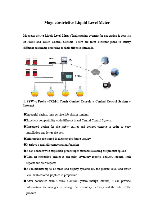
Magnetostrictive Liquid Level MeterMagnetostrictive Liquid Level Meter (Tank gauging system) for gas station is consists of Probe and Touch Control Console. There are three different plans to satisfy different customers according to their effective demands.1. SYW-A Probe +TCM-1 Touch Control Console +Central Control System + Internet●Industrial design, long service life, fast in running.●Excellent compatibility with different brand Central Control System.●Integrated design for the safety barrier and control console in order to easy installation and lower the cost.●Information are stored in memory for future inquiry.●It enjoys a tank tilt compensation function●It can connect with explosion-proof ringer outdoors avoiding the product spilled●With an embedded printer it can print inventory reports, delivery reports, leak reports and shift reports●It can monitor up to 12 tanks and display dynamically the product level and water level with colored graphics in proportion.●After connected with Central Control System though internet, it can provide information for manager to manage the inventory, delivery and the sale of the product.2. SYW-A Probe +TCM-2 Touch Control Console + Central Control System + Internet●Industrial design, long service life, fast in running.●Excellent compatibility with different brand Cen tral Control System.●Integrated design for the safety barrier and control console in order to easy installation and lower the cost.●With an embedded printer it can print inventory reports, delivery reports, leak reports and shift reports●It can connect with explosion-proof ringer outdoors avoiding the product spilled●It can monitor up to 6 tanks and display dynamically the product level and water level with graphics in proportion.SYW-A Magnetostrictive Probe●The probe consist of:Fully enclosed magnetostrictive probe.Electronic Pod using for data measuring and transforming.Floater made according to the product.●Features:Safety: ExiaIIBT4 (Intrinsically safe) issued by PCECAccuracy: level accuracy is ±0.5mmStability: strong anti-jamming abilityEfficiency: less than 1 second to test one tank.TCM-1 Touch Control Console●It can monitor up to 12 tanks and monitor the delivery conditions, it also enjoys a static leak test function.●It can display product level, water level, temperature, volume, ullage.●It enjoys a tank tilt compensation function.●It can display dynamically the change of product level and water level with graphics in proportion, it features a 7 inch colored touch-screen console panel, and each interface displays 4 graphics.●It features an audible and visual alarm function with front panel.●It comes with two RS-232 serial interface communication ports to connect with different brand Center Console.●It enjoys a record function, all information are stored in memory for future queries ●There is an embedded printer in it to print inventory reports, delivery reports, leak reports and shift reports.●It can calculate volume of product by multipoint, which can fully ensure the accuracy of volume of the product.●After connected with Center Console though internet, it can provide information in long-distance for manager to arrange the inventory.●It can monitor the oil pump according to the product level, which can avoid the product spilled and pumpdown..●It can connect with flow-meter to display delivery information constantly.TCM-2 Touch Control Console●It can monitor up to 6 tanks and monitor the delivery conditions, it also enjoys a static leak test function.●It can display product level, water level, temperature, volume, and ullage.●It can display dynamically the change of product level and water level with graphics and scale, it features a touch-screen console panel, and each interface displays 4 graphics.●It features an audible and visual alarm function with front panel.●It comes with two RS-232 serial interface communication ports to connect with different brand Center Console.●There is an embedded printer in it to print inventory reports, delivery reports, leak reports and shift reports.●It can calculate volume of product by multipoint, which can fully ensure the accuracy of volume of the product.GH-300 Tank Volume Table Calibration Systemnecessary to calibrate the tank volume tableThe nonstandard manufacturing, tilted installation of the tank will easy to cause the volume table inaccurate. This means a loss to the gas station.Operational principleThis system consists of Tank V olume Table Calibration Instrument, Liquid Level Meter, Special Software and computer.Fill the tank up, pump out the product to another tank or tanker though the Tank V olume Table Calibration Instrument, the product volume would be calculated automatically and the data would be uploaded to computer. Meanwhile, the data of product level collected by Liquid Level Meter uploaded to computer as well. According to the data uploaded, the Special Software will do analyze and process, and finally generate an accurate electronic volume table.Characteristic●Need not manual operate whole processing, generate the volume table automatically.●This system can operate individually whether there is a computer.●It’s easy to use the software.●It’s convenient to move with compact design.●The fuel pump will never pumpdown as the system can setup a lowest product levellimit.●The volume table is accurate as its error rate is 3‰~5‰●With fast operate speed , it’s less than 2.5 hours to measure a tank with 30m³●It features a protection function to avoid the data losing.●Users can import directly the volume table generated by this system into the Word or Excel.Management SoftwareManagement Software for Liquid Level Meter Information Inquiry (Network) Performance●Customers can inquiry and manage all the gas stations online.●It can monitored the current status of the tank, delivery reports and the dailyclosing.●Display the product level, water level, temperature, ullage, volume.●Display dynamically the change of product level and water level with graphics inproportion.●Alarm information of the tanks.●UpgradeableManagement Software for Liquid Level Meter Information Inquiry (Client)●It can monitor up to 16 tanks and display product level, water level, temperature, volume, ullage.●Display dynamically the change of product level and water level with graphics and scale●It enjoys an alarm function.●The tank status , delivery reports, leak reports and daily closing can be stored in memory for inquiry and printed.●UpgradeableGuidelines Before InstallationStructural drawing of gas stationGuidelines before the liquid level meter installation.(液位仪安装前施工指南)In order to ensure the installation successfully, you should make preparations as follows,1.Welding the vertical-pipe and blind plate on the manhole cover of the tank (As shown inFigure 1.)2.Cable wiring (As shown in Figure2.)3.Renovation of the control room (As shown in Figure3.)Working standard1.Far away from the thank farm and other unsafe area.2. The Power Ground in control room should be reliableFigure 1. Reformation of the wall of manholeReformation of the vertical-pipe●The DN100 vertical-pipe should be perpendicular to the manhole cover when welding. The part of the vertical-pipe entering the manhole cover should less than 50mm, and the pipe inside surface should be smoothly and no welding slag.●In order to avoid the floater get stuck, there should no barrier from the welding part of the vertical-pie to the bottom of the tank.●The part of the galvanized pipe exposed from the wall of manhole length of 100mm, its outer thread (G3/4) length of 25mm. The length of the communication cable exposed from the pipe is 500-600mm (as shown in Figure 1), and please ensure that there is no barrier within 150mm around it and 300mm ahead of it.●Welding a galvanized pipe length of 50mm (it’s outer thread G3/4 length of 25mm) on the center of the blind plate.●Put asbestos pad between flange and blind plate, and cross them with copper row.Figure 2. WiringWiring●Connect each probe with the Touch Control Console using a communication cable, all the cables put into galvanized pipe (connect with elbow at the corner). Don’t damage the insulation sleeve of the cable when wiring.●Give numbers to the cable according to the number of the tank, in order to distinguish them.●The communication cables of the Liquid Level Meter should not with other cables in the same pipe, and please keep them away from other cables more than 400mm..Figure 3. Control room of the gas stationRenovation of the control room●Position of Touch Control Console : As shown in Figure 3, drill two 60mm deep and Φ8mm diameter holes, the space between the holes is 270mm for TCC-1 and 250mm for TCM-2. Two bolts Φ8x48, two screws ST4X60.●Wiring: The communication cable channel should get the horizontal or vertical line, connect with elbow at the corner. An allowance for cable is 0.5m under the Control Console.●Power Ground: Power Ground of Control Console and the socket should be reliable. Power Ground resistance should less than 4Ω, its material should be flexible cooper wire, has a diameter of ≥4mm2 , the power socket should within 1.5m away from Control Console.●Galvanized pipe: The galvanized pipe using for containing cable should above control room ground more than 200mm, and sealed the mouth of the pipe with explosion- plasticine.●Wiring for outdoors explosion-proof ringer from the Touch Control Console to the ringer. An allowance for cable is 2m at the area of ringer installation, 0.5m under the Control Console.Blind PlateWelding the vertical-pipe with blind plateVertical-pipeManhole cover of the tankAsbestos padWorking standard1.Try to welding the vertical-pipe on the line of the tank diameter.2.The vertical-pipe should be perpendicular to the product level in the tank.3.The pipe inside surface should be smoothly and no welding slag.4.No barrier under the vertical-pie.Blind plate standard1.The installation holes on the blind plate should be math with the pipe flange.2.The welding should be smoothly and no welding slag.3.Paint antirust or aluminum paint on surface.Vertical-pipe standard1. The clearance between the vertical-pipe and flange should no be too large.2. Try to welding the vertical-pipe on the line of the tank diameter.3. The pipe inside and outside surface should be smoothly and no welding slag.4. The vertical-pipe should be perpendicular to the product level in the tank.5. No barrier under the vertical-pie.6. Paint antirust or aluminum paint on surface.7. The part of the vertical-pipe entering the manhole cover should less than 50mmMeasuring mothed before installation1.h1 : it’s the height from the top surface of the manhole cover to the bottom of the tank2.h2 : it’s the height of vertical-pipe from the top surface of the vertical-pipe flange to the topsurface of the manhole cove. Here is the size of vertical-pipe we recommended: 400mm above the manhole cover, 50mm under the cover.3. D (diameter of the tank): it’s the valid max inside diameter of the tank.4.L (length of the tank): it’s the valid max inside length of the tank.Notes: If install the probe from the gauge hatch, you need to add a vertical-pipe at the top of the gauge hatch, and it’s total height of the vertical-pipe and the gauge hatch is more than 400mm.。
基于单片机液位控制器设计的外文文献

Structure and function of the MCS-51 series one-chip computerMCS-51 is a name of a piece of one-chip computer series which Intel Company produces. This company introduced 8 top-grade one-chip computers of MCS-51 series in 1980 after introducing 8 one-chip computers of MCS-48 series in 1976. It belong to a lot of kinds this line of one-chip computer the chips have,such as 8051, 8031, 8751, 80C51BH, 80C31BH,etc., their basic composition, basic performance and instruction system are all the same. 8051 daily representatives- 51 serial one-chip computersAn one-chip computer system is made up of several following parts: (1) One microprocessor of 8 (CPU). (2) At slice data memory RAM (128B/256B),it use not depositting not can reading /data that write,such as result not middle of operation, final result and data wanted to show,etc.. (3) Procedure memory ROM/EPROM (4KB/8KB ), is used to preserve the procedure , some initial data and form in slice. But does not take ROM/EPROM within some one-chip computers, such as 8031 , 8032, 80C ,etc..(4)Four 8 run side by side I/O interface P0 four P3, each mouth can use as introduction , may use as exporting too. (5) Two timer / counter, each timer / counter may set up and count in the way, used to count to the external incident, can set up into a timing way too, and can according to count or result of timing realize the control of the computer. (6) Five cut off cutting off the control system of the source . (7) One all duplexing serial I/O mouth of UART (universal asynchronous receiver/transmitter (UART) ), is it realize one-chip computer or one-chip computer and serial communication of computer to use for. (8) Stretch oscillator and clock produce circuit, quartz crystal finely tune electric capacity need outer. Allow oscillation frequency as 12 megahertzs now at most. Every the above-mentioned part was joined through the inside data bus .Among them, CPU is a core of the one-chip computer, it is the control of the computer and command centre, made up of such parts as arithmetic unit and controller ,etc.. The arithmetic unit can carry on 8 persons of arithmetic operation and unit ALU of logic operation while including one, the 1 storing device temporarilies of 8, storing device 2 temporarily, 8's accumulation device ACC, register B and procedure state register PSW,etc.. Person who accumulate ACC count by 2 input ends entered of checking etc. temporarily as one operation often, come from person who store 1 operation is it is it make operation to go on to counttemporarily , operation result and loopback ACC with another one. In addition, ACC is often regarded as the transfer station of data transmission on 8051 inside . The same as general microprocessor, it is the busiest register. Help remembering that agreeing with A expresses in the order. The controller includes the procedure counter , the order is deposited, the order decipher, the oscillator and timing circuit,etc.. The procedure counter is made up of counter of 8 for two, amounts to 16. It is a byte address counter of the procedure in fact, the content is the next IA that will carried out in PC. The content which changes it can change the direction that the procedure carries out . Shake the circuit in 8051 one-chip computers, only need outer quartz crystal and frequency to finely tune the electric capacity , its frequency range is its 12MHZ of 1.2MHZ. This pulse signal, as 8051 basic beats of working, namely the minimum unit of time. 8051 is the same as other computers, the work in harmony under the control of the basic beat , just like an orchestra according to the beat play that is commanded.There are ROM (procedure memory , can only read ) and RAM in 8051 slices (data memory, can is it can write ) two to read, they have each independent memory address space, dispose way to be the same with general memory of computer. Procedure 8051 memory and 8751 slice procedure memory capacity 4KB, address begin from 0000H, used for preserving the procedure and form constant. Data 8051- 8751 8031 of memory data memory 128B, address false 00FH, use for middle result to deposit operation, the data are stored temporarily and the data are buffered etc.. In RAM of this 128B, there is unit of 32 bytes that can be appointed as the job register, this and general microprocessor is different, 8051 slice RAM and job register rank one formation the same to arrange the location. It is not very the same that the memory of MCS-51 series one-chip computer and general computer disposes the way in addition. General computer for first address space, ROM and RAM can arrange in different space within the range of this address at will , namely the addresses of ROM and RAM, with distributing different address space in a formation. While visiting the memory, corresponding and only an address Memory unit,can ROM, it can be RAM too, and by visiting the order similarly. This kind of memory structure is called the structure of Princeton. 8051 memories are divided into procedure memory space and data memory space on the physics structure, there are four memory spaces in all: The procedure stores in one and data memory space outside data memory and one in procedure memory space and one outside one, the structureforms of this kind of procedure device and data memory separated form data memory, called Harvard structure. But use the angle from users, 8051 memory address space is divided into three kinds: ( 1) In the slice , arrange blocks of FFFFH , 0000H of location , in unison outside the slice (use 16 addresses). ( 2) The data memory address space outside one of 64KB, the address is arranged from 0000H 64KB FFFFH (with 16 addresses ) too to the location. ( 3) Data memory address space of 256B (use 8 addresses). Three above-mentioned memory space addresses overlap, for distinguishing and designing the order symbol of different data transmission in the instruction system of 8051: CPU visit slice, ROM order spend MOVC , visit block RAM order uses MOVX outside the slice, RAM order uses MOV to visit in slice. 8051 one-chip computer have four 8 walk abreast I/O port , call P0, P1, P2 and P3. Each port is 8 accurate two-way mouths, accounts for 32 pins altogether. Every one I/O line can be used as introduction and exported independently. Each port includes a latch (namely special function register ), one exports the driver and a introduction buffer . Make data can latch when outputting , data can buffer when making introduction , but four function of passway these self-same. Expand among the system of memory outside having slice, four port these may serve as accurate two-way mouth of I/O in common use. Expand among the system of memory outside having slice, P2 mouth see high 8 address off; P0 mouth is a two-way bus , send the introduction of 8 low addresses and data / export in timesharingThe circuit of 8051 one-chip computers and four I/O ports is very ingenious in design. Familiar with I/O port logical circuit, not only help to use ports correctly and rationally , and will inspire to designing the peripheral logical circuit of one-chip computer to some extent . Load ability and interface of port have certain requirement, because output grade, P0 of mouth and P1 end output, P3 of mouth grade different at structure, so, the load ability and interface of its door demand to have nothing in common with each other. P0 mouth is different from other mouths, its output grade draws the resistance supremly . When using it as the mouth in common use to use , output grade is it leak circuit to turn on , is it is it urge NMOS draw the resistance on taking to be outer with it while inputting to go out to fail. When being used as introduction , should write " 1 " to a latch first . Every one with P0 mouth can drive 8 Model LS TTL load to export. P1 mouth is an accurate two-way mouth too, used as I/O in common use . Different from P0 mouth output of circuit its, draw load resistance linkwith power on inside have. In fact, the resistance is that two effects are in charge of FET and together: One FET is in charge of load, its resistance is regular. Another one can is it lead to work with close at two state , make its President resistance value change approximate 0 or group value heavy two situation very. When it is 0 that the resistance is approximate , can draw the pin to the high level fast ; When resistance value is very large, P1 mouth, in order to hinder the introduction state high. Output as P1 mouth high electricity at ordinary times , can is it draw electric current load to offer outwards , draw the resistance on needn't answer and thenning. Here When the port is used as introduction , must write into 1 to the corresponding latch first too, make FET end . Relatively about 20,000 ohms because of the load resistance in scene and because 40,000 ohms, will not exert an influence on the data that are input . The structure of P2 some mouth is similar to P0 mouth, there are MUX switches. Is it similar to mouth partly to urge, but mouth large a conversion controls some than P1. P3 mouth one multi-functional port, mouth getting many than P1 it have " and " 3 door and 4 buffer". Two part these, make her besides accurate two-way function with P1 mouth just, can also use the second function of every pin . " and " door 3 function one switch in fact, it determines to be to output data of latch to output second signal of function. Act as W =At 1 o'clock, output Q end signal; Act as Q =At 1 o'clock, can output W line signal . At the time of programming, it is that the first function is still the second function but needn't have software that set up P3 mouth in advance . It hardware not inside is the automatic to have two function outputted when CPU carries on SFR and seeks the location (the location or the byte ) to visit to P3 mouth /at not lasting lining, there are inside hardware latch Qs =1.The operation principle of P3 mouth is similar to P1 mouth.Output grade , P3 of mouth , P1 of P1 , connect with inside have load resistance of drawing , every one of they can drive 4 Model LS TTL load to output. As while inputting the mouth, any TTL or NMOS circuit can drive P1 of 8051 one-chip computers as P3 mouth in a normal way . Because draw resistance on output grade of them have, can open a way collector too or drain-source resistance is it urge to open a way, do not need to have the resistance of drawing outerly . Mouths are all accurate two-way mouths too. When the conduct is input, must write the corresponding port latch with 1 first . As to 80C51 one-chip computer, port can only offer milliampere of output electric currents, is it output mouth go when urging oneordinary basing of transistor to regard as, should contact a resistance among the port and transistor base , in order to the electricity while restraining the high level from exporting P1~P3 Being restored to the throne is the operation of initializing of an one-chip computer. Its main function is to turn PC into 0000H initially , make the one-chip computer begin to hold the conduct procedure from unit 0000H. Except that the ones that enter the system are initialized normally,as because procedure operate it make mistakes or operate there aren't mistake, in order to extricate oneself from a predicament , need to be pressed and restored to the throne the key restarting too. It is an input end which is restored to the throne the signal in 8051 China RST pin. Restore to the throne signal high level effective , should sustain 24 shake cycle (namely 2 machine cycles ) the above its effective times. If 6 of frequency of utilization brilliant to shake, restore to the throne signal duration should exceed 4 delicate to finish restoring to the throne and operating. Produce the logic picture of circuit which is restored to the throne the signal:Restore to the throne the circuit and include two parts outside in the chip entirely. Outside that circuit produce to restore to the throne signal (RST ) hand over to Schmitt's trigger, restore to the throne circuit sample to output , Schmitt of trigger constantly in each S5P2 , machine of cycle in having one more , then just got and restored to the throne and operated the necessary signal insidly. Restore to the throne resistance of circuit generally, electric capacity parameter suitable for 6 brilliant to shake, can is it restore to the throne signal high level duration greater than 2 machine cycles to guarantee. Being restored to the throne in the circuit is simple, its function is very important. Pieces of one-chip computer system could normal running,should first check it can restore to the throne not succeeding. Checking and can pop one's head and monitor the pin with the oscillograph tentatively, push and is restored to the throne the key, the wave form that observes and has enough range is exported (instantaneous), can also through is it restore to the throne circuit group holding value carry on the experiment to change.MCS-51系列单片机的结构及功能MCS-51是Intel公司生产的一个单片机系列的名称。
外文翻译---基于声学驻波的液位检测方法
附录2 中英文翻译英文原文:A New Level Measurement Method based on Acoustic Standing WaveWang ZhiWen Cheng-linXu Xiao-bin Li Zhi-liangHangzhou DianzhiUniversityEmail:metero3377692@AbstractA new level measurement method based on acoustic standing wave is presented. Firstly, the system model about the frequencies of the acoustic standing waves is established and Kalman Filter is used to preprocess the standing wave frequency. It will increase the accuracyof level measurement by reducing the influence of environment noise and measurement error, which are usually ignored by most of acoustic level measurement methods. Secondly, the new conversion technique can be given to calculate the level height with estimates of standing wave frequencies from Kalman Filter. And it can overcome the strict limitation about frequency range in existing classical method. Moreover, the experiments show the proposed method effective.1. IntroductionThe level measurement methods based on sound reflection phenomena have been used successfully in some areas of the process industry [1-2](waste water treatment, chemical, petroleum, etc.). And the method based on the acoustic standing wave reflection is important among them. The sound waves are emitted vertical to the liquid surface and the echo signals will be sent to the controller. Then the level height will be calculated by terms of the character of the standing waves extracted from the echo signals [3].The common standing wave methods are simply equipped with single waveguide tube. It is necessary to measure sound velocity for accurate calculation of level height. However, the exact value of sound velocity can hardly computed, because it’s a complex physical quantity related mainly to temperature, gascomposition, and gas pressure in changeful measurement environment. In order to avoid appearance of sound velocity, reference [3] presents a standing wave method with double waveguide tubes, which can compensate sound velocity. Although this method increases the accuracy in some degree, it brings other problem that the acoustic frequencies of emitted waves must start strictly from 0Hz so as to capture the first standing wave, by which, the level height can be computed. So, the microphone receiving the echo must be very sensitive to the low frequency sound wave. Whereas, the lowest frequency that the common microphone can capture is about 20Hz.High-quality microphone that can feel the frequency below 20Hz are 10 times more expansive than the former. Considering the cost of level gauge, it is undesirable to choose the latter. For overcoming this strict limitation a new height conversion technique is given to ensure that the user can choose a suitable range of frequencies, which make the requirement that that wave be emitted from 0Hz unnecessary. On the other hand, most of the present acoustic level measurement methods directly use the measurementsof the standing wave frequencies to compute level height. The measurement error and environmental noise often lead to decline of measuring accuracy which is a common shortage for them.This paper establishes the system model about the frequencies of the acoustic standing waves and uses Kalman Filterto preprocess the standing wave frequency. The new conversion technique can be used to calculate level height with estimates of standing wave frequencies from Kalman filter. The proposed method will increase the accuracy of the result by reducing the influence of environment noise and measurement error, meanwhile overcome the strict limitation about frequency range. Moreover, the experiments show the proposed method effective. 2. The level measurement method with double tubes based on acoustic standing wave theoryIf two waves propagate in the opposite directionwith the same frequency,amplitude and the velocity, standing waves will be formed[7]. When the sound waves travel in the direction vertical to the level, the above conditions can be satisfied. Let y1 be the acoustic wave from the transmitter and y2 be the reflection of y1 through the liquid surface. Expressionsof both are respectivelyy 1 = A cos 2 π ( ft − L λ )(1)y 2 = A cos 2 π ( ft + L λ )(2)And their synthesized wave isy = 2 A cos(2 π L λ )cos(2 π ft) (3)Where A is the amplitude of acoustic wave, f is the frequency, L is the distance from the liquid surface to the top of tube, λ is the wavelength of the acoustic wave. L is the level height needed to be calculated. When λ and L satisfy the relation belowL = 2 n λ ,n = 1,2, (4)the amplitude of the synthesized wave will reach the peak. Its wavelength is λ=c/f , and thenL = nc (2f) (5)Where c is the sound velocity, f is the acoustic frequency and T is the centigrade.Figure.1 Level gauge with single tubeFigure.3 Level gauge with double tubesFigure.2 Waveform graphFigure.1 shows a setup of level gauge with single tube. When the transmitter emits sound waves vertical to the fluid surface whose frequencies change with uniform speed, the microphone receives the resonance and sends the signal to the controller. Figure.2 shows the synthesized sine waves which are changed at equal time intervals when sine wave frequencies change from 1000Hz to 2500Hz. Here the vertical axis denotes the amplitude and the lateral axis denotes the frequency.It’s easy to capture the frequencies of standing waves that are corresponding to the different wave crests. Then, when f and c are given, L will be calculated by (5). It is noteworthy that every amplitude of the standing wave should be same theoretically. However, there are differences between them because of effects of the environment noise and measurement error. Fortunately, it does not influence extract of the frequencies of the standing waves.The level height L is correlated with c, so whether c is accurate or not will[5-6].c=6)γ is the ratio of heat capacities of the gas, R is universal gas constant, M is molecular mass of the gas and T is absolute temperature.Because of the complex gas composition, it’s difficult to get the accurate sound velocity and it will affect the measurement to L. The best way to deal with this problem is not using sound velocity in the process of calculating.A level measurement method with double tubes is presented in [3]. Figure.3 shows its setup, the left long tube is the main waveguide tube (MT) and the other one is the auxiliary waveguide tube (AT).During the conversion process, the length difference between both can be used to reduce c so as to avoid inaccurate c to final result. L1 and L2 denote the distance respect-tively from the liquid surface to the top of the MT and the AT. The length difference between them isd=L 1-L 2 (7)121212,22n c n c L L f f ==, 1212()2n n c d f f =-(8) then 2212211///f n L d f n f n =-(9) Where f1, f2 are the frequencies of the standing wavesin MT and ATrespectively. In [3], n1=n2 ishypothesized and equation (9) becomesL = df ( f − f ) (10)This method requires that the acoustic frequencies of emitted waves startstrictly from 0Hz so asto capture the first standing wave, by which the level height can be computed. So, the microphone must be very sensitive to the lowfrequency sound waves.Whereas, the lowest frequency that the common microphone can capture is about 20Hz. High-quality microphone that can feel the frequency below 20Hz are 10 times more expansive than the former. On the other hand, there were some performance losses for the microphone when it has worked for a long time. That is to say, its sensitivity to the low frequency sound waves will quite decrease. Therefore, it is hard to ensure that frequency of the first standing wave can be captured all the time.3. A new level measurement method based on acoustic standing waveSo, the strict requirement to the selection of the acoustic frequency range and the parameter n1,n2 limits the application for method in [3]. In order to overcome the above limitations, this section presents anew level measurementmethod. Firstly, a new technique of level height conversion is given to avoid calculating n1, n2.Secondly, a system model of the frequencies of the acoustic standing waves are established, based on which, Kalman Filter is used to preprocess the standing wave frequencies, and then the L can be calculated by new conversion technique with estimates of f1, f2.The proposed method will increase the accuracy of the resultby reducing the influence ofenvironment noise and measurement error.3.1. A new conversion techniqueRegard f1/n1 and f2/n2 as two constants and take f1/n1for an example. If the measurement sets {f1(k)} are known, k denotes the k-th standing wave, k=1,2…, then111121(1)(2)(2)(1)(2)(1)1f f f n n n ==+(11) After reducing and trimming, one can obtain1111(1)/(1)(2)(1)f n f f =-(12)According to the incomplete induction, the general form of f1(k)/n1(k) is1111()/()(1)()f k n k f k f k =+-(13)As long as the continuous two standing wave frequencies are known, one can calculate the correspondingf1(k)/n1(k) by (13). Obviously, the measurements are a group of standing wave frequencies. Because of environment noise and measurement error, it is not convincible to use only two continuous frequencies. Therefore, a weighted plus strategy is present to obtain a statistically optimal result.For{ f (k ) n (k )} , one can get its weighted mean f n . Similarly to f 1, f n can be calculated about the frequency f 2. Substituting f nand f ninto (9), thelevel height will be calculated.3.2. Filtering stepsThis section gives the recursive state equation and measurement equation about the frequencies of the standing waves. Subsequently, Kalman Filter is used to preprocess the frequencies.Take f1 for an example to explain the filtering stepsexactly. f1(n) denotes the frequency of the n-th standing wave in the main waveguide tube and n = 1,2,... Following equations are derived by (5) 1/(2(),1,,1L nc f n n k k k ==-+(14)After reducing and trimming, one can get111(2)2(1)()f k f k f k +=+-(15)LetX (k )=11()(1)f k f k ⎛⎫ ⎪+⎝⎭andA=0112⎛⎫ ⎪-⎝⎭。
液位监控系统毕业设计(外文翻译)

液位监控系统毕业设计(外文翻译)摘要本设计是以德国FESTO公司PCS实验平台中的液位单元为被控对象,设计了液位监控系统,初步研究了网络的引入对液位控制系统性能可能产生的影响。
在液位控制系统的总体监控方案设计中,首先采用SIMATIC WinCC组态软件对液位控制系统进行上位监控设计;然后根据测量数据建立控制系统模型,并进行PID参数的整定,使系统达到了设计指标;最后讨论了网络化控制系统中时延和数据丢包问题,并利用同时集成系统控制与网络调度的仿真工具TrueTime,分析研究了网络对液位控制系统性能的影响。
关键词:PCS 液位控制WinCC PID 网络化TrueTimeAbstractBased on the German FESTO company liquid level units in the PCS experimental platform for the controlled object, the liquid level monitoring system is designed and some preliminary researches are discussed for the influences which caused by introduction of the network of liquid level control system performance. In the liquid level control of the whole system design of monitoring schemes, first using the SIMATIC WinCC configuration software realize the upper monitor design of liquid level control system ,and then based on the measurement data establish control system model,and through PID parameter adjusting making the system to reach the design index. Finally, time delay and data-packet-dropout problems for networked control systems are discussed, and proceed analytical investigation for the network to the liquid level control system performance impact using integrated control and scheduling of the simulation tools TrueTime.Keywords: PCS Level -Control WinCC PID Network TrueTime目录摘要Abstract第一章概述 (1)1.1 研究的技术背景 (1)1.2 研究的目的和意义 (1)1.3 研究的主要内容、功能及技术指标 (2)第二章方案论证 (3)2.1 PCS实验平台及液位控制单元简介 (3)2.1.1 PCS实验平台简介 (3)2.1.2 液位控制单元简介 (4)2.2 上位监控组态软件的选择 (4)2.3 西门子S7-300 (6)2.3.1 S7-300PLC介绍 (6)2.3.2 Step7介绍 (7)2.4 液位控制单元上下位通讯方式选择 (7)2.5控制方式选择 (8)2.6 总体方案确定 (8)第三章液位控制系统上位监控设计 (10)3.1 组态软件WinCC V6.0概述 (10)3.1.1 WinCC V6.0 软件简介 (10)3.1.2 WinCC各部分组成和功能介绍 (10)3.2 硬件组态和网络组态 (14)3.2.1 硬件组态 (14)3.2.2 网络组态 (18)3.3 变量参数统计分析 (19)3.3.1 上位通讯 (19)3.3.2 数据变量建立 (20)3.4 监控画面制作和动画连接 (20)3.4.1 初始画面的设计 (21)3.4.2 监控主界面设计 (22)3.4.3 系统报警窗口设计 (22)3.4.4 实时趋势窗口设计 (25)3.4.4 系统报表的设计 (27)3.5 Matlab在线控制 (29)3.5.1 Matlab基础 (29)3.5.1 Matlab与WinCC通讯的建立 (29)3.6 运行调试 (32)第四章液位控制系统建模及控制器参数整定 (34)4.1 系统的数学模型 (34)4.1.1 建立系统数学模型的目的 (35)4.1.2 建立系统数学模型的基本方法 (35)4.2 系统建模 (36)4.2.1 阶跃响应曲线法建模 (36)4.2.2 最小二乘法模型辨识 (40)4.3 控制器参数整定 (44)4.3.1 PID控制器简介 (44)4.3.2 参数整定原则 (45)4.3.3 PID参数计算及分析 (45)4.3.4 史密斯(Smith)预估补偿方案 (48)4.4 系统调试 (49)4.4.1 响应曲线法PID控制 (49)第五章网络化控制系统的性能研究 (52)5.1 网络化控制系统的基本结构和存在的问题 (52)5.1.1 网路控制系统的基本结构 (52)5.1.2 网络控制系统中的几个基本问题的分析 (53)5.2 网络仿真工具的选择 (54)5.3 TrueTime仿真工具箱 (55)5.3.1 TrueTime工具箱介绍 (55)5.3.2 TrueTime1.5初始化 (56)5.4 网络化对液位控制系统性能影响的研究 (57)5.4.1 网络化对液位控制系统仿真模型的建立 (57)5.4.2 网络时延对液位控制系统性能影响的研究 (58)5.4.3 数据丢包对液位控制系统性能影响的研究 (60)5.4.4 网络时延和数据丢包对液位控制系统性能影响的综合研究 . 62第六章毕业设计总结 (64)参考文献 (65)外文原文和译文 (66)致谢 (95)附录 (96)第一章概述1.1 研究的技术背景近几十年来,控制系统已被广泛应用,在研究和发展上也已趋于完备,控制的概念更是应用在许多生活周围的事物。
pid控制外文加中文文献(适用于毕业论文外文翻译+中英文对照)
PID controllerFrom Wikipedia, the free encyclopediaA proportional–integral–derivative controller (PID controller) is a generic .control loop feedback mechanism widely used in industrial control systems.A PID controller attempts to correct the error between a measured process variable and a desired setpoint by calculating and then outputting a corrective action that can adjust the process accordingly.The PID controller calculation (algorithm) involves three separate parameters; the Proportional, the Integral and Derivative values. The Proportional value determines the reaction to the current error, the Integral determines the reaction based on the sum of recent errors and the Derivative determines the reaction to the rate at which the error has been changing. The weightedsum of these three actions is used to adjust the process via a control element such as the position of a control valve or the power supply of a heating element.By "tuning" the three constants in the PID controller algorithm the PID can provide control action designed for specific process requirements. The response of the controller can be described in terms of the responsiveness of the controller to an error, the degree to which the controller overshoots the setpoint and the degree of system oscillation. Note that the use of the PID algorithm for control does not guarantee optimal control of the system or system stability.Some applications may require using only one or two modes to provide the appropriate system control. This is achieved by setting the gain of undesired control outputs to zero. A PID controller will be called a PI, PD, P or I controller in the absence of the respective control actions. PI controllers are particularly common, since derivative action is very sensitive to measurement noise, and the absence of an integral value may prevent the system from reaching its target value due to the control action.A block diagram of a PID controllerNote: Due to the diversity of the field of control theory and application, many naming conventions for the relevant variables are in common use.1.Control loop basicsA familiar example of a control loop is the action taken to keep one's shower water at the ideal temperature, which typically involves the mixing of two process streams, cold and hot water. The person feels the water to estimate its temperature. Based on this measurement they perform a control action: use the cold water tap to adjust the process. The person would repeat this input-output control loop, adjusting the hot water flow until the process temperature stabilized at the desired value.Feeling the water temperature is taking a measurement of the process value or process variable (PV). The desired temperature is called the setpoint (SP). The output from the controller and input to the process (the tap position) is called the manipulated variable (MV). The difference between the measurement and the setpoint is the error (e), too hot or too cold and by how much.As a controller, one decides roughly how much to change the tap position (MV) after one determines the temperature (PV), and therefore the error. This first estimate is the equivalent of the proportional action of a PID controller. The integral action of a PID controller can be thought of as gradually adjusting the temperature when it is almost right. Derivative action can be thought of as noticing the water temperature is getting hotter or colder, and how fast, and taking that into account when deciding how to adjust the tap.Making a change that is too large when the error is small is equivalent to a high gain controller and will lead toovershoot. If the controller were to repeatedly make changes that were too large and repeatedly overshoot the target, this control loop would be termed unstable and the output would oscillate around the setpoint in either a constant, growing, or decaying sinusoid. A human would not do this because we are adaptive controllers, learning from the process history, but PID controllers do not have the ability to learn and must be set up correctly. Selecting the correct gains for effective control is known as tuning the controller.If a controller starts from a stable state at zero error (PV = SP), then further changes by the controller will be in response to changes in other measured or unmeasured inputs to the process that impact on the process, and hence on the PV. Variables that impact on the process other than the MV are known as disturbances and generally controllers are used to reject disturbances and/or implement setpoint changes. Changes in feed water temperature constitute a disturbance to the shower process.In theory, a controller can be used to control any process which has a measurable output (PV), a known ideal value for that output (SP) and an input to the process (MV) that will affect the relevant PV. Controllers are used in industry to regulate temperature, pressure, flow rate, chemical composition, speed and practically every other variable for which a measurement exists. Automobile cruise control is an example of a process which utilizes automated control.Due to their long history, simplicity, well grounded theory and simple setup and maintenance requirements, PID controllers are the controllers of choice for many of these applications.2.PID controller theoryNote: This section describes the ideal parallel or non-interacting form of the PID controller. For other forms please see the Section "Alternative notation and PID forms".The PID control scheme is named after its three correcting terms, whose sum constitutes the manipulated variable (MV). Hence:where Pout, Iout, and Dout are the contributions to the output from the PID controller from each of the three terms, as defined below.2.1. Proportional termThe proportional term makes a change to the output that is proportional to the current error value. The proportional response can be adjusted by multiplying the error by a constant Kp, called the proportional gain.The proportional term is given by:WherePout: Proportional outputKp: Proportional Gain, a tuning parametere: Error = SP − PVt: Time or instantaneous time (the present)Change of response for varying KpA high proportional gain results in a large change in the output for a given change in the error. If the proportional gain is too high, the system can become unstable (See the section on Loop Tuning). In contrast, a small gain results in a small output response to a large input error, and a less responsive (or sensitive) controller. If the proportional gain is too low, the control action may be too small when responding to system disturbances.In the absence of disturbances, pure proportional control will not settle at its target value, but will retain a steady state error that is a function of the proportional gain and the process gain. Despite the steady-state offset, both tuning theory and industrial practice indicate that it is the proportional term that should contribute the bulk of the output change.2.2.Integral termThe contribution from the integral term is proportional to both the magnitude of the error and the duration of the error. Summing the instantaneous error over time (integrating the error) gives the accumulated offset that should have been corrected previously. The accumulated error is then multiplied by the integral gain and added to the controller output. The magnitude of the contribution of the integral term to the overall control action is determined by the integral gain, Ki.The integral term is given by:Change of response for varying KiWhereIout: Integral outputKi: Integral Gain, a tuning parametere: Error = SP − PVτ: Time in the past contributing to the integral responseThe integral term (when added to the proportional term) accelerates themovement of the process towards setpoint and eliminates the residual steady-state error that occurs with a proportional only controller. However, since the integral term is responding to accumulated errors from the past, it can cause the present value to overshoot the setpoint value (cross over the setpoint and then create a deviation in the other direction). For further notes regarding integral gain tuning and controller stability, see the section on loop tuning.2.3 Derivative termThe rate of change of the process error is calculated by determining the slope of the error over time (i.e. its first derivative with respect to time) and multiplying this rate of change by the derivative gain Kd. The magnitude of the contribution of the derivative term to the overall control action is termed the derivative gain, Kd.The derivative term is given by:Change of response for varying KdWhereDout: Derivative outputKd: Derivative Gain, a tuning parametere: Error = SP − PVt: Time or instantaneous time (the present)The derivative term slows the rate of change of the controller output and this effect is most noticeable close to the controller setpoint. Hence, derivative control isused to reduce the magnitude of the overshoot produced by the integral component and improve the combined controller-process stability. However, differentiation of a signal amplifies noise and thus this term in the controller is highly sensitive to noise in the error term, and can cause a process to become unstable if the noise and the derivative gain are sufficiently large.2.4 SummaryThe output from the three terms, the proportional, the integral and the derivative terms are summed to calculate the output of the PID controller. Defining u(t) as the controller output, the final form of the PID algorithm is:and the tuning parameters areKp: Proportional Gain - Larger Kp typically means faster response since thelarger the error, the larger the Proportional term compensation. An excessively large proportional gain will lead to process instability and oscillation.Ki: Integral Gain - Larger Ki implies steady state errors are eliminated quicker. The trade-off is larger overshoot: any negative error integrated during transient response must be integrated away by positive error before we reach steady state.Kd: Derivative Gain - Larger Kd decreases overshoot, but slows down transient response and may lead to instability due to signal noise amplification in the differentiation of the error.3. Loop tuningIf the PID controller parameters (the gains of the proportional, integral and derivative terms) are chosen incorrectly, the controlled process input can be unstable, i.e. its output diverges, with or without oscillation, and is limited only by saturation or mechanical breakage. Tuning a control loop is the adjustment of its control parameters (gain/proportional band, integral gain/reset, derivative gain/rate) to the optimum values for the desired control response.The optimum behavior on a process change or setpoint change varies depending on the application. Some processes must not allow an overshoot of the processvariable beyond the setpoint if, for example, this would be unsafe. Other processes must minimize the energy expended in reaching a new setpoint. Generally, stability of response (the reverse of instability) is required and the process must not oscillate for any combination of process conditions and setpoints. Some processes have a degree of non-linearity and so parameters that work well at full-load conditions don't work when the process is starting up from no-load. This section describes some traditional manual methods for loop tuning.There are several methods for tuning a PID loop. The most effective methods generally involve the development of some form of process model, then choosing P, I, and D based on the dynamic model parameters. Manual tuning methods can be relatively inefficient.The choice of method will depend largely on whether or not the loop can be taken "offline" for tuning, and the response time of the system. If the system can be taken offline, the best tuning method often involves subjecting the system to a step change in input, measuring the output as a function of time, and using this response to determine the control parameters.Choosing a Tuning MethodMethodAdvantagesDisadvantagesManual TuningNo math required. Online method.Requires experiencedpersonnel.Ziegler–NicholsProven Method. Online method.Process upset, sometrial-and-error, very aggressive tuning.Software ToolsConsistent tuning. Online or offline method. May includevalve and sensor analysis. Allow simulation before downloading.Some costand training involved.Cohen-CoonGood process models.Some math. Offline method. Only good for first-order processes.3.1 Manual tuningIf the system must remain online, one tuning method is to first set the I and D values to zero. Increase the P until the output of the loop oscillates, then the P shouldbe left set to be approximately half of that value for a "quarter amplitude decay" type response. Then increase D until any offset is correct in sufficient time for the process. However, too much D will cause instability. Finally, increase I, if required, until the loop is acceptably quick to reach its reference after a load disturbance. However, too much I will cause excessive response and overshoot. A fast PID loop tuning usually overshoots slightly to reach the setpoint more quickly; however, some systems cannot accept overshoot, in which case an "over-damped" closed-loop system is required, which will require a P setting significantly less than half that of the P setting causing oscillation.3.2Ziegler –Nichols methodAnother tuning method is formally known as the Ziegler –Nichols method, introduced by John G . Ziegler and Nathaniel B. Nichols. As in the method above, the I and D gains are first set to zero. The "P" gain is increased until it reaches the "critical gain" Kc at which the output of theloop starts to oscillate. Kc and the oscillation period Pc are used to set the gains as shown:3.3 PID tuning softwareMost modern industrial facilities no longer tune loops using the manualcalculation methods shown above. Instead, PID tuning and loop optimization software are used to ensure consistent results. These software packages will gather the data, develop process models, and suggest optimal tuning. Some software packages can even develop tuning by gathering data from reference changes.Mathematical PID loop tuning induces an impulse in the system, and then uses the controlled system's frequency response to design the PID loop values. In loops with response times of several minutes, mathematical loop tuning is recommended, because trial and error can literally take days just to find a stable set of loop values. Optimal values are harder to find. Some digital loop controllers offer a self-tuning feature in which very small setpoint changes are sent to the process, allowing the controller itself to calculate optimal tuning values.Other formulas are available to tune the loop according to different performance criteria.4 Modifications to the PID algorithmThe basic PID algorithm presents some challenges in control applications that have been addressed by minor modifications to the PID form.One common problem resulting from the ideal PID implementations is integralwindup. This can be addressed by:Initializing the controller integral to a desired valueDisabling the integral function until the PV has entered the controllable region Limiting the time period over which the integral error is calculatedPreventing the integral term from accumulating above or below pre-determined boundsMany PID loops control a mechanical device (for example, a valve). Mechanical maintenance can be a major cost and wear leads to control degradation in the form of either stiction or a deadband in the mechanical response to an input signal. The rate of mechanical wear is mainly a function of how often a device is activated to make a change. Where wear is a significant concern, the PID loop may have an output deadband to reduce the frequency of activation of the output (valve). This is accomplished by modifying the controller to hold its output steady if the changewould be small (within the defined deadband range). The calculated output must leave the deadband before the actual output will change.The proportional and derivative terms can produce excessive movement in the output when a system is subjected to an instantaneous "step" increase in the error, such as a large setpoint change. In the case of the derivative term, this is due to taking the derivative of the error, which is very large in the case of an instantaneous step change.5. Limitations of PID controlWhile PID controllers are applicable to many control problems, they can perform poorly in some applications.PID controllers, when used alone, can give poor performance when the PID loop gains must be reduced so that the control system does not overshoot, oscillate or "hunt" about the control setpoint value. The control system performance can be improved by combining the feedback (or closed-loop) control of a PID controller with feed-forward (or open-loop) control. Knowledge about the system (such as the desired acceleration and inertia) can be "fed forward" and combined with the PID output to improve the overall system performance. The feed-forward value alone can often provide the major portion of the controller output. The PID controller can then be used primarily to respond to whatever difference or "error" remains between the setpoint (SP) and the actual value of the process variable (PV). Since the feed-forward output is not affected by the process feedback, it can never cause the control system to oscillate, thus improving the system response and stability.For example, in most motion control systems, in order to accelerate a mechanical load under control, more force or torque is required from the prime mover, motor, or actuator. If a velocity loop PID controller is being used to control the speed of the load and command the force or torque being applied by the prime mover, then it is beneficial to take the instantaneous acceleration desired for the load, scale that value appropriately and add it to the output of the PID velocity loop controller. This means that whenever the load is being accelerated or decelerated, a proportional amount of force is commanded from the prime mover regardless of the feedback value. The PID loop in this situation uses the feedback information to effect any increase or decrease of the combined output in order to reduce the remaining difference between theprocess setpoint and thefeedback value. Working together, the combined open-loop feed-forward controller and closed-loop PID controller can provide a more responsive, stable and reliable control system.Another problem faced with PID controllers is that they are linear. Thus, performance of PID controllers in non-linear systems (such as HV AC systems) is variable. Often PID controllers are enhanced through methods such as PID gain scheduling or fuzzy logic. Further practical application issues can arise from instrumentation connected to the controller. A high enough sampling rate, measurement precision, and measurement accuracy are required to achieve adequate control performance.A problem with the Derivative term is that small amounts of measurement or process noise can cause large amounts of change in the output. It is often helpful to filter the measurements with a low-pass filter in order to remove higher-frequency noise components. However, low-pass filtering and derivative control can cancel each other out, so reducing noise by instrumentation means is a much better choice. Alternatively, the differential band can be turned off in many systems with little loss of control. This is equivalent to using the PID controller as a PI controller.6. Cascade controlOne distinctive advantage of PID controllers is that two PID controllers can be used together to yield better dynamic performance. This is called cascaded PID control. In cascade control there are two PIDs arranged with one PID controlling the set point of another. A PID controller acts as outer loop controller, which controls the primary physical parameter, such as fluid level or velocity. The other controller acts as inner loop controller, which reads the output of outer loop controller as set point, usually controlling a more rapid changing parameter, flowrate or accelleration. It can be mathematically proved that the working frequency of the controller is increased and the time constant of the object is reduced by using cascaded PID controller.[vague]7. Physical implementation of PID controlIn the early history of automatic process control the PID controller was implemented as a mechanical device. These mechanical controllers used a lever, spring and a mass and were often energized by compressed air. These pneumatic controllers were once the industry standard.Electronic analog controllers can be made from a solid-state or tube amplifier, a capacitor and a resistance. Electronic analog PID control loops were often found within more complex electronic systems, for example, the head positioning of a disk drive, the power conditioning of a power supply, or even the movement-detection circuit of a modern seismometer. Nowadays, electronic controllers have largely been replaced by digital controllers implemented with microcontrollers or FPGAs.Most modern PID controllers in industry are implemented in software in programmable logic controllers (PLCs) or as a panel-mounted digital controller. Software implementations have the advantages that they are relatively cheap and are flexible with respect to the implementation of the PID algorithm.8.Alternative nomenclature and PID forms8.1 PseudocodeHere is a simple software loop that implements the PID algorithm:8.2 Ideal versus standard PID formThe form of the PID controller most often encountered in industry, and the one most relevant to tuning algorithms is the "standard form". In this form the Kp gain is applied to the Iout, and Dout terms, yielding:WhereTi is the Integral TimeTd is the Derivative TimeIn the ideal parallel form, shown in the Controller Theory sectionthe gain parameters are related to the parameters of the standard formthroughand Kd = KpTd. This parallel form, where the parameters are treated as simple gains, is the most general and flexible form. However, it is also the form where the parameters have the least physical interpretation and is generally reserved for theoretical treatment of the PID controller. The "standard" form, despite being slightly more complex mathematically, is more common in industry.8.3Laplace form of the PID controllerSometimes it is useful to write the PID regulator in Laplace transform form:Having the PID controller written in Laplace form and having the transfer function of the controlled system, makes it easy to determine the closed-loop transfer function of the system.8.4Series / interacting formAnother representation of the PID controller is the series, or "interacting" form. This form essentially consists of a PD and PI controller in series, and it made early (analog) controllers easier to build. When the controllers later became digital, many kept using the interacting form.[edit] ReferencesLiptak, Bela (1995). Instrument Engineers' Handbook: Process Control. Radnor, Pennsylvania: Chilton Book Company, 20-29. ISBN 0-8019-8242-1.Van, Doren, Vance J. (July 1, 2003). "Loop Tuning Fundamentals". Control Engineering. Red Business Information.Sellers, David. An Overview of Proportional plus Integral plus Derivative Control and Suggestions for Its Successful Application and Implementation (PDF). Retrieved on 2007-05-05.Articles, Whitepapers, and tutorials on PID controlGraham, Ron (10/03/2005). FAQ on PID controller tuning. Retrieved on2007-05-05.PID控制器比例积分微分控制器(PID调节器)是一个控制环,广泛地应用于工业控制系统里的反馈机制。
液位控制系统中英文对照外文翻译文献

液位控制系统中英⽂对照外⽂翻译⽂献中英⽂对照翻译The liquid level control system based ondde\matlab\simulinkProcess control is an important application field of automatic technology, it is to point to the level, temperature, flow control process variables, such as in metallurgy, machinery, chemical, electric power, etc can be widely used. Especially liquid level control technology in real life, played an important role in production, for example, the water supply, civil water tower if low water levels, can affect people's lives in water; Industrial enterprises with water, if the drainage water drainage or controlled properly or not, in relation to the workshop of condition; Boiler drum, if the control level boiler is too low, can make level boiler overheating, possible accident; Jing flow, liquid level control tower control accuracy and level of the craft can influence the quality of the products and the cost, etc. In these production field, are basically labor strength or the operation has certain risk nature of work, extremely prone to accidents caused by operating error, the losses, killing manufacturer. Visible, in actual production, liquid level control accuracy and control effects directly affect the factory production cost and economic benefit of safety coefficient. Even equipment So, in order to ensure safety, convenient operation, you have to research the development of a d v a n c e d l e v e l c o n t r o l m e t h o d s a n d s t r a t e g i e s.The graduation design topic is the liquid level control system based on dde\matlab\simulink\force control, Among them was controlled object for tank level, Communication mode for DDE communications , Matlab is mainly used in the simulation test ,And force control software used for modeling, This system mainly through combination of hardware and software device to achieve precise control of liquid level , In modern industry level control of important component, it influence upon production not allow to ignore, in order to ensure safety in production and the product quality and quantity, the level and perform effective control is very necessary, The following is a description of all aspects:⼀PID controllerA proportional–integral–derivative controller (PID controller) is a generic .control loop feedback mechanism widely used in industrial control systems.A PID controller attempts to correct the error between a measured process variable and a desired set point by calculating and then outputting a corrective action that can adjust the process accordingly.The PID controller calculation (algorithm) involves three separate parameters; the Proportional, the Integral and Derivative values. The Proportional value determines the reaction to the current error, the Integral determines the reaction based on the sum of recent errors and the Derivative determines the reaction to the rate at which the error has been changing. The weighted sum of these three actions is used to adjust the process via a control element such as the position of a control valve or the power supply of a heating element. By "tuning" the three constants in the PID controller algorithm the PID can provide control action designed for specific process requirements. The response of the controller can be described in terms of the responsiveness of the controller to an error, the degree to which the controller overshoots the set point and the degree of system oscillation. Note that the use of the PID algorithm for control does not guarantee optimal control of the system or system stability.Some applications may require using only one or two modes to provide the appropriate system control. This is achieved by setting the gain of undesired control outputs to zero. A PID controller will be called a PI, PD, P or I controller in the absence of the respective control actions. PI controllers are particularly common, since derivative action is very sensitive to measurement noise, and the absence of an integral value may prevent the system from reaching its target value due to the control action.1.Control loop basicsA familiar example of a control loop is the action taken to keep one's shower water at the ideal temperature, which typically involves the mixing of two process streams, cold and hot water. The person feels the water to estimate its temperature. Based on this measurement they perform a control action: use the cold water tap to adjust the process. The person would repeat this input-output control loop, adjusting the hot water flow until the process temperature stabilized at the desired value.Feeling the water temperature is taking a measurement of the process value or process variable (PV). The desired temperature is called the set point (SP). The output from the controller and input to the process (the tap position) is called the manipulated variable (MV). The difference between the measurement and the set point is the error (e), too hot or too cold and by how much. As a controller, one decides roughly how much to change the tap position (MV) after one determines the temperature (PV), and therefore the error. This first estimate is the equivalent of the proportional action of a PID controller. The integral action of a PID controller can be thought of as gradually adjusting the temperature when it is almost right.Derivative action can be thought of as noticing the water temperature is getting hotter or colder, and how fast, and taking that into account when deciding how to adjust the tap,Making a change that is too large when the error is small is equivalent to a high gain controller and will lead to overshoot. If the controller were to repeatedly make changes that were too large and repeatedly overshoot the target, this control loop would be termed unstable and the output would oscillate around the set point in either a constant, growing, or decaying sinusoid. A human would not do this because we are adaptive controllers, learning from the process history, but PID controllers do not have the ability to learn and must be set up correctly. Selecting the correct gains for effective control is known as tuning the controller.If a controller starts from a stable state at zero error (PV = SP), then further changes by the controller will be in response to changes in other measured or unmeasured inputs to the process that impact on the process, and hence on the PV. Variables that impact on the process other than the MV are known as disturbances and generally controllers are used to reject disturbances and/or implement set point changes. Changes in feed water temperature constitute a disturbance to the shower process.In theory, a controller can be used to control any process which has a measurable output (PV), a known ideal value for that output (SP) and an input to the process (MV) that will affect the relevant PV. Controllers are used in industry to regulate temperature, pressure, flow rate, chemical composition, speed and practically every other variable for which a measurement exists. Automobile cruise control is an example of a process which utilizes automated control.Due to their long history, simplicity, well grounded theory and simple setup and maintenance requirements, PID controllers are the controllers of choice for many ofthese applications.2.PID controller theoryNote: This section describes the ideal parallel or non-interacting form of the PID controller. For other forms please see the Section "Alternative notation and PID forms".The PID control scheme is named after its three correcting terms, whose sum constitutes the manipulated variable (MV). Hence:where Pout, Iout, and Dout are the contributions to the output from the PID controller from each of the three terms, as defined below.2.1. Proportional termThe proportional term makes a change to the output that is proportional to the current error value. The proportional response can be adjusted by multiplying the error by a constant Kp, called the proportional gain.The proportional term is given by:WherePout: Proportional outputKp: Proportional Gain, a tuning parametere: Error = SP ? PVt: Time or instantaneous time (the present)Change of response for varying KpA high proportional gain results in a large change in the output for a given change in the error. If the proportional gain is too high, the system can become unstable (See the section on Loop Tuning). In contrast, a small gain results in a small output response to a large input error, and a less responsive (or sensitive) controller. If the proportional gain is too low, the control action may be too small when responding to system disturbances.In the absence of disturbances, pure proportional control will not settle at its target value, but will retain a steady state error that is a function of the proportional gain and the process gain. Despite the steady-state offset, both tuning theory and industrial practice indicate that it is the proportional term that should contribute the bulk of the output change.2.2.Integral termThe contribution from the integral term is proportional to both the magnitude of the error and the duration of the error. Summing the instantaneous error over time (integrating the error) gives the accumulated offset that should have been corrected previously. The accumulated error is then multiplied by the integral gain and added to the controller output. The magnitude of the contribution of the integral term to the overall control action is determined by the integral gain, Ki.The integral term is given by:Iout: Integral outputKi: Integral Gain, a tuning parametere: Error = SP ? PVτ: Time in the past contributing to the integral responseThe integral term (when added to the proportional term) accelerates the movement of the process towards set point and eliminates the residual steady-state error that occurs with a proportional only controller. However, since the integral term is responding to accumulated errors from the past, it can cause the present value to overshoot the set point value (cross over the set point and then create a deviation in the other direction). For further notes regarding integral gain tuning and controller stability, see the section on loop tuning.2.3 Derivative termThe rate of change of the process error is calculated by determining the slope of the error over time (i.e. its first derivative with respect to time) and multiplying this rate of change by the derivative gain Kd. The magnitude of the contribution of the derivative term to the overall control action is termed the derivative gain, Kd.The derivative term is given by:Dout: Derivative outputKd: Derivative Gain, a tuning parametere: Error = SP ? PVt: Time or instantaneous time (the present)The derivative term slows the rate of change of the controller output and this effect is most noticeable close to the controller setpoint. Hence, derivative control isused to reduce the magnitude of the overshoot produced by the integral component and improve the combined controller-process stability. However, differentiation of a signal amplifies noise and thus this term in the controller is highly sensitive to noise in the error term, and can cause a process to become unstable if the noise and the derivative gain are sufficiently large.2.4 SummaryThe output from the three terms, the proportional, the integral and the derivative terms are summed to calculate the output of the PID controller. Defining u(t) as the controller output, the final form of the PID algorithm is:and the tuning parameters areKp: Proportional Gain - Larger Kp typically means faster response since thelarger the error, the larger the Proportional term compensation. An excessively large proportional gain will lead to process instability and oscillation.Ki: Integral Gain - Larger Ki implies steady state errors are eliminated quicker. The trade-off is larger overshoot: any negative error integrated during transient response must be integrated away by positive error before we reach steady state.Kd: Derivative Gain - Larger Kd decreases overshoot, but slows down transient response and may lead to instability due to signal noise amplification in the differentiation of the error.⼆Matlab IntroductionThe MATLAB? environment is well suited to rapid prototyping and application development. The interactive programming environment, built-in math functions, toolboxes, editing and debugging tools, and deployment options all contribute to reducing your overall development time.By using the built-in math functions and the many specialized functions contained within our toolboxes, MATLAB can significantly reduce the time it takes you to develop prototypes. In addition to integrated editing and debugging tools, MATLAB provides a performance profiler to help you further optimize your code when programming in MATLAB.Building applications around complex algorithms and graphics is easier than everwith the GUI builder, GUIDE. GUIDE was redesigned in MATLAB 6 to save you time. It offers all the drag and drop interface options you would expect, such as text boxes, radio buttons, check boxes, listboxes, sliders, pop-up menus, frames and more.When you're ready to deploy your application, the MathWorks offers a number of different options that allow you to either convert or interface your MATLAB application to other environments including C/C++ and the Web. MATLAB is the most productive development environment for creating scientific and engineering applications because it offers powerful tools for every step in the process to reduce your overall development time.MATLAB is a high-performance language for technical computing. It integrates computation, visualization, and programming in an easy-to-use environment where problems and solutions are expressed in familiar mathematical notation. Typical uses includeMath and computationAlgorithm developmentData acquisitionModeling, sim ulation, and prototypingData analysis, exploration, and visualizationScientific and engineering graphicsApplication development, including graphical user interface building三DDE IntroductionDynamic data exchange (DDE, Dynamic data exchange) is real-time exchange data between applications, it is the effective method between different applications to share data a agreement. DDE agreement is a kind of open, and language unrelated, based on protocol, it allows multiple applications to any human agreed format data exchange or command. It is application through Shared memory process of the communication between a form, also need not user intervention of good data exchange method.DDE applications can be divided into four types: client and server and client/server and the monitor. Conversation is a basic concept of DDE. DDE conversation happened in client applications and server application between. Customer is responsible for initializing and attendant session and control conversation flow, from the server application request data or services; The server applicationresponse client applications of data or service request. Client/server applications is both client applications and server application request, it can be and can provide information. Monitor application for debugging purposes. DDE applications can have multiple burst conversation, a service applications can also have multiple client applications, a client applications can to multiple requests data service applications, and an application can also act as client applications and services applications, when don't need the service application data or service, the customer will terminate session. DDE agreement must be synchronous control the news session, but in different application can switch between asynchronous session. DDE Application using the three layer identification system: Application name apply), theme name (from) and project name (Item). Application name (also called service name) is located at the top of the hierarchical structure, the service application registration for pointed out that particular DDE server application name, customer the application wants to establish session with the server application must be specified application name when this string marks; Name in every conversation topics is one and to identify logical data connection string, is the total classification, data it defines a server application conversation theme content, the server application can support one or more theme name; Project name identifies exchange unit of data string, furthermore confirm the conversation of detailed information, every theme name may have one or more project name.Example: for a database interface applications, will it supports database name as a theme name, and will all sorts of SQL commands as project name, because the server application can support one or more theme, and each theme name name may have one or more project name; So, when to change or reconstruct a conversation, just changing the subject name or project name can.四force control IntroductionForce control is Beijing SANWEI force control technology and "soft" control strategy software, real-time database and its management system, Web portal of tools and other products. These products are not isolated, and the force control is an application scale can free the system structure, the whole expansion force control system and its various products are made from some components procedures according to certain combinations and become. So this guide is not specifically targeted specific products separately describes the use of method, but the common use of all products introduced method. Force control configuration software is a can run on Windows 98/2000 / NT environment, and can run on Windows CE, DOS embedded environment control fu- nctions such as software modules. It USES function diagram way for users provide interface, possess and real-time database, graphical interface system and communication function.Force charged with monitoring configuration software is to the field production data acquisition and process control of specialized software, the biggest characteristic is to flexible "configuration mode" instead of programming approach to system integration, and it provides a good user interface and simple engineering development, as long as the realization method of software module of pre-settings simple "configuration", it can easily realization and complete monitoring layer each function, shorten the automation engineer system integration time, greatly improve the efficiency of integration.Force charged with monitoring configuration software is in the automatic control system monitoring layer level software platform, it can also and the domestic and foreign various industrial control network communication equipment manufacturer, it is ok with high reliable industrial controlling computer and network system integration, can achieve the purpose of the centralized management and monitoring, and can also be convenient to control layer and management for software and hardware to implement all the interface, with "third party" hardware and software systems for integration.The control strategy in the force control, an application in generator may have a lot of control strategy, but only one main strategy. The Lord, the Lord was first execution strategy calls. Other strategies strategy Strategy nested grade 4, namely for most 0 ~ 3 level, in this category 4, grade 3 0 level supreme, the lowest. Senior strategy can call low-level strategy, and low-level strategy can't call senior strategy. In addition to tier 3 most can have 127 strategy outside, other three grades maximum respectively are 255 strategy. Control strategy of by some basic function blocks, a function blocks represent an operation, algorithm or variables. Function blocks basic execution element is strategy, similar to an integrated circuit blocks, have several input and output, each input and output tube feet all have the only name.Force control control strategy is in control strategy, edited generated generators in automatic control strategy for strategies when inventory compiled, and check grammar mistakes, compile can also manually. Control strategy, and you can also call between if A strategy was B strategy calls, says A is B son strategy. A functional block can be repeated calls, each calls are automa- tically entitled to a name by. The executive order and function block in the position of screen on the upper left, position relevant function block, according to priority execution left after the first order under implementation.Force control control strategy of basic function blocks generator was divided into five categories: variable function blocks, mathematical operation function blocks, program control function blocks, logic function blocks function block and control algorithm.基于matlab\dde\simulink\⼒控的液位控制系统过程控制是⾃动技术的重要应⽤领域,它是指对液位、温度、流量等过程变量进⾏控制,在冶⾦、机械、化⼯、电⼒等⽅⾯得到了⼴泛应⽤。
液位控制系统英文
International Railway JournalLevel Control System【Title 】 International Railway Journal【Publication Date 】2008【No.】 period MarchIon Matei, Dumitru Popescu, Ciprian Lupu, llie LuicanPolitehnica University of Bucharest - Control and Computer ScienceFacultySplaiul Independentei nr.313,sector6,Bucurcsti,Romaniaemail: inion @3 home .ro1 Level control systemThe fluid flow is controlled by an electric pomp. The process inputis a voltage with values between 0 and 10 V and the output is the fluid level measured by an ultrasounds transducer. The process is nonlinear but it is approximated with linear mathematical model around a representative point of functioning. The approximated mathematical model which wasobtained using the sample period Te = 5s.It is important to mention that for designing a numerical regulatorthree steps must be followed:- computing the discrete model;- performances specification;- computing the adequate control algorithmIn this case for the level control were used the next numerical controlalgorithms: RST and PID with its two variants, PIDl and PID2. Thesealgorithms have different performances so that the students will have the opportunity to compare them. First it will be presented the RST algorithm and than the paper will continue with PID algorithms which will bestructured analyzed and compared to the first one.2 PID algorithmNumerical PID algorithm comes from sampling the continuous PIDalgorithm with all appropriate sampling period.Numerical PID controllers are suitable only for processes modeled bya second order transfer function with or without pure delay.It is worth to mention that some numerical PID controllers do not havea continuous equivalent.2.1 PIDl numerical algorithmLet us consider the algorithm:The transfer functions of a continuous PID controller ,This algorithmis specified by four parameters:K - proportional action;T i - integral action; T d - derivative action; T d - filtered derivative action. There are many methods that can be used to sample this algorithmresulting in a numerical controller of the same form. As it may be seen, PIDl numerical regulator has also four parameters (r th r 1 r 2, s 1) as its continuous form. This algorithm can be InternationalRailway Journalstructured in a RST form if T(q-1)=R(q-1 ).It is easy to notice that PIDl is one freedom degree algorithm. The transfer function in closed loop which join the reference r(t) with the output y(i) is, where P(q-1)defines the poles wanted in closed loop that determine the performances for perturbations rejection. PIDl algorithm introduces new zeros in closed loop by polynomial R(q-1) that alter the performances. This negative effect will be partially eliminated by the PID2 algorithm. Having already determined the RST algorithms it is now easy to calculate the PIDl parameters (if the rejection performances define by P (q-1) are not changed) because the polynomials R(q-1) and S(q-1) will be the same [3].As it may be observed in the next graphics the perforinanccs of the PIDl algorithm are inferior to the RST algorithm.2.2 PID2 numerical algorithmAs it was noticed above the PIDl regulator introduces supplementary zeros in closed loop by polynomial T(q-1)=R(q-1). Those zeros affect specially the control performances as it was observed in figure 7. This disadvantage can be partially eliminated if the polynomial T(q-1) is chosen.assuring in this manner a unitary transfer function in stationary regime [3].The block schematics of the PID2 numerical algorithm structured as RST is presented bellow.This algorithm assures superior performances compare to PIDl as it may be seen in the next graphics.3 RST numerical algorithmFor any control system there are defined two important objectives:1 . Reference 's tracking;2 . Rejection of the perturbations;A classical control structure. with only one liberty degree (fig. 2) has the great disadvantage that it can not fulfill the two objective defined above.As it may be noticed the command is not pondered differentially by reference and measure. This means that some performances defined for perturbations rejection could restrict the reference tracking. If the polynomial R(q-1), which filter the reference, is replaced by another polynomial T(q-1) i t will lead to a RST structure with two liberty degree that accepts different performances in tracking and rejection[3] [4].The block structure of the RST numerical algorithm is presented in the next figure:The closed loop transfer function is:The performances for rejection are established by characteristic polynomial P(q-1) obtained by sampling a second order continuous system. The polynomials R(q-1) and S(q-1) results from solving the next polynomial equation:A(q-1)S(q-1)+ q-d B(q-1)R(q-1)= P(q-1) (4)The tracking performances are controlled by T(q-1) and reference filtering. The polynomial T(q-1) is chosen so that the close loop International Railway Journaltransfer is unitary (the output will follow the imposed reference y*).T(q-1)=P(q-1) (5)Tracking dynamics can be modify by polynomials Bm(q-1) and Am(q-1)which filter the reference:Polynomials Bm, and Am, result also from sampling a second order continuous system. Therefore choosing the parameters and will determinethe tracking performances [4].The block diagram of the RST control structure with filtered referenceis presented below:The system tracking performances are chosen by a second order systemwith ,I = 0.25, = 0.99 which results in:The rejection performances are also given by a second order system with:n= 2.5, = 0.8.The characteristic polynomial for the poles allocation method, will become:P(q-1)=1 - 1.2807q-1 + 0.4493q-2 (8)Solving the system (4) and applying (5) results in:R(q-1)=5.1232 - 6.5q-1 + 2.0516q-2 (9)S(q-1) = 1 - 11.432q-1 + 0.4321q-2 (10)T(q-1)=6.3423 - 9.281q-1 + 3.6137q-2 (11)System response to step and perturbations rejection are presented inthe figure below:4 Virtual experimentThe experiment presented in this paper is a part of the laboratoryactivity of “Identification and Control Systems”, course dedicated tothe forth year students from the UPB-Control and Computer Science Faculty.The laboratory purpose is to train students in practical activity ofsystem identification and numerical process control. During this part ofthe practical activity the students have the possibility to control thelevel fluid from a tank by testing different type of numerical algorithms.In the figure IO is presented an image of the level control didactical platform.The lab activity. in the virtual version proposed.is structures in twoparts. In the first part students practice the open loop identificationof the studied process, the presence of the students in the laboratory being necessary. The second part of the lab consists in numeric control of the identified process by testing various algorithms. For this section of thelab the prescnce of the students in the laboratory is not compulsory becausethe activity could be undertaken from any place with an internet connection.The virtual experment is formed from two components: a hardware and osoftware structure.4.1 Hardware structureThe base of this experiment is a hardware structure composed from:- an acquisition board with analog to digital and digital to analog converters which acquires and send data to the process;- a PC compatible IBM with a Pentium II – 350 MHz processor and 64Mbytes RAM, which contain the acquisition board;- a video camera for real-time images broadcasting;International Railway Journal- a HP LH3 server for Internet connection4.2 Software structureThe software structure is formed by to subsystems which allow access to the didactical platform local as well as distant - using the Internet as it may be observe in figure 10: The first subsystem represents a program written in Lab Windows/CVI. It runs on the computer connected to the process and allows direct local access to the platform. This application represents a gate for the data that leave and come to the process.The second subsystem is a client-server application which assures distant interaction with the process.4.2.1 Local accessThe program for local access was created using Lab Windows/CVI and it is an independent application that allows local access to the platform independent towards the distant access.This program makes the connection with the process acquiring and sending data from respectively to the process. The data is sent further on to thc clients applications via the Internet.The local application assures a fcw operations over the platform such as:- reference changing;- automat/manual regime changing;- manual command;- algorithms configuration.For an easy use, the local program has a graphical user interface (GUI) presented bellow.4.2.2 Distance accessThe base of the distant communication is a clientserver application. There are some key words that define such an architecture which will be described as follows:Server - entity that accepts requests and offers services to the clients connected to him [5]. For this experiment the server is a program written in Java which runs on HP LH3 server machine. The server connects itself to the local application and become a proxy for the clients that connect to him. The server is a multithreading program that runs in background and sends periodically data about the state of the process to the clients. Theoretically it can accept an infinite number of client connections but the number is limited by software to maintain a certain level of performances.Client - software entity which sends requests to the server and process the data received as answer [5].For this experiment the client is a Java applet incorporated in a web page. Next to the applet there arc presented live images with the process evolution.International Railway Journal5. ConclusionsIn this paper a level control system with distant access option thatallows monitoring and updating of important parameters of the system is presented.There are presented the base theory for level control and the hardware and software structures for distant access via the Internet.A comparative study for performance evolution of different control algorithms can be realized.The system has been created as an educational tool through the students can experiment distant access to a technological platform.。
PLC液位控制系统 外文翻译
本科生毕业设计(论文)外文翻译题目:基于S700-PLC连铸结晶器液位控制系统学院:环化系过程装备与测控工程专业:测控技术与仪器班级:测仪093班学号:5801209094姓名:邱发生指导教师:张宇填表日期:2013 年 3 月28 日基于S7–300PLC污水处理自动控制系统的设计与实现白京京∙赵子贤∙鲍春红∙冯仕广内蒙古大学电子工程学院∙呼和浩特∙中国摘要随着县级城市家庭污水处理的需求,市政污水处理自动化系统中的分散控制系统应运而生,通过WinCC组态软件和西门子S7-300PLC来监控每个子系统市政污水处理情况,这个系统主要特征如下:收集PLC数据、协议转换、光纤传输数据、组态软件的实现、实时数据在数据库中的存储以及显示各类报表、曲线及警报等。
本报刊介绍这个系统设计思路以及详细的特征。
关键字:污水处理;分散控制系统;西门子S7-300PLC ;WinCC组态软件1、引言随着中国经济的快速发展,环境保护成为日益突出的话题,污水处理是环境保护中最重要的一部分。
由于计算机技术和污水处理技术的快速发展,很有必要采用先进的控制技术和设备来监控污水处理过程。
内蒙古呼和浩特土黑特左旗的污水处理工程就是呼和浩特市政级城市典型的一种,它通过使用循环活性污泥系统来处理污水。
这个工程中,我实际用了一个基于西门子S7-300PLC和WinCC6.2的监控软件的DCS系统。
2、循环活性污泥系统工程循环活性污泥微生物处理系统是一种多参数(如液位、水质、流动速率、压力等)、多任务(进水、通风、沉淀、排水等)、多设备(沉降器、鼓风机、校准器等)的复杂系统,它是整个微生物处理系统的核心。
循环活性污泥系统池主要反应区通过“通风—静止—沉淀—排水”的循环过程。
而在其中,循环活性污泥池的氧气溶解控制,厌氧段控制,好氧段控制是核心。
表格1.污水处理流程图3、控制系统的结构污水处理自动控制系统的结构是集中式管理控制和分散式控制。
此控制系统采用了结合远程控制自动控制、远程人工控制和字段自动控制方法。
外文翻译--结晶器液位控制系统设计与实现

结晶器液位控制系统设计与实现Abstract : A simple effective intelligent mould level control method is presented. It consistes of a nonlinear controller , for sliding valve and its hydraulic actuator based on model reduction and inner model control , a feed forward tundish weight controller and a mould level predictive fuzzy controller. Its accuracy and reliability for practical use in continuous casting process are demonstrated by satisfactory experimental and on- line control performances .Key wor ds : mould level ; intelligent control ; cascade control ; fuzzy predictive controlDocument code : A摘要:提出了一种简单有效的结晶器液位智能控制控制方法,它包括一个基于模型降阶和内模控制的非线性滑动水口及其液压机构控制器、一个中间包重量前馈控制器和一个结晶器液位模糊预测控制器. 实验和现场使用表明,该方法能够准确可靠地应用于连铸过程控制之中.关键词: 结晶器液位; 智能控制; 串级控制; 模糊预测控制1 引言结晶器液位控制是连铸过程控制的重要环节之一。
它是通过液压伺服系统控制钢液从中间包流向结晶器的流量。
结晶器中液位的波动不仅会影响铸坯质量,而且还可能导致浇铸过程中溢钢或漏钢事故。
- 1、下载文档前请自行甄别文档内容的完整性,平台不提供额外的编辑、内容补充、找答案等附加服务。
- 2、"仅部分预览"的文档,不可在线预览部分如存在完整性等问题,可反馈申请退款(可完整预览的文档不适用该条件!)。
- 3、如文档侵犯您的权益,请联系客服反馈,我们会尽快为您处理(人工客服工作时间:9:00-18:30)。
液位控制系统论文中英文资料对照外文翻译The liquid level control system based ondde\matlab\simulinkProcess control is an important application field of automatic technology, it is to point to the level, temperature, flow control process variables, such as in metallurgy, machinery, chemical, electric power, etc can be widely used. Especially liquid level control technology in real life, played an important role in production, for example, the water supply, civil water tower if low water levels, can affect people's lives in water; Industrial enterprises with water, if the drainage water drainage or controlled properly or not, in relation to the workshop of condition; Boiler drum, if the control level boiler is too low, can make level boiler overheating, possible accident; Jing flow, liquid level control tower control accuracy and level of the craft can influence the quality of the products and the cost, etc. In these production field, are basically labor strength or the operation has certain risk nature of work, extremely prone to accidents caused by operating error, the losses, killing manufacturer. Visible, in actual production, liquid level control accuracy and control effects directly affect the factory production cost and economic benefit of safety coefficient. Even equipment So, in order to ensure safety, convenient operation, you have to research the development of a d v a n c e d l e v e l c o n t r o l m e t h o d s a n d s t r a t e g i e s.The graduation design topic is the liquid level control system based on dde\matlab\simulink\force control, Among them was controlled object for tank level, Communication mode for DDE communications , Matlab is mainly used in the simulation test ,And force control software used for modeling, This system mainly through combination of hardware and software device to achieve precise control of liquid level , In modern industry level control of important component, it influence upon production not allow to ignore, in order to ensure safety in production and the product quality and quantity, the level and perform effective control is very necessary, The following is a description of all aspects:一PID controllerA proportional–integral–derivative controller (PID controller) is a generic .control loop feedback mechanism widely used in industrial control systems.A PID controller attempts to correct the error between a measured process variable and a desired set point by calculating and then outputting a corrective action that can adjust the process accordingly.The PID controller calculation (algorithm) involves three separate parameters; the Proportional, the Integral and Derivative values. The Proportional value determines the reaction to the current error, the Integral determines the reaction based on the sum of recent errors and the Derivative determines the reaction to the rate at which the error has been changing. The weighted sum of these three actions is used to adjust the process via a control element such as the position of a control valve or the power supply of a heating element. By "tuning" the three constants in the PID controller algorithm the PID can provide control action designed for specific process requirements. The response of the controller can be described in terms of the responsiveness of the controller to an error, the degree to which the controller overshoots the set point and the degree of system oscillation. Note that the use of the PID algorithm for control does not guarantee optimal control of the system or system stability.Some applications may require using only one or two modes to provide the appropriate system control. This is achieved by setting the gain of undesired control outputs to zero. A PID controller will be called a PI, PD, P or I controller in the absence of the respective control actions. PI controllers are particularly common, since derivative action is very sensitive to measurement noise, and the absence of an integral value may prevent the system from reaching its target value due to the control action.1.Control loop basicsA familiar example of a control loop is the action taken to keep one's shower water at the ideal temperature, which typically involves the mixing of two process streams, cold and hot water. The person feels the water to estimate its temperature. Based on this measurement they perform a control action: use the cold water tap to adjust the process. The person would repeat this input-output control loop, adjusting the hot water flow until the process temperature stabilized at the desired value.Feeling the water temperature is taking a measurement of the process value or process variable (PV). The desired temperature is called the set point (SP). The output from the controller and input to the process (the tap position) is called the manipulated variable (MV). The difference between the measurement and the set point is the error (e), too hot or too cold and by how much. As a controller, one decides roughly how much to change the tap position (MV) after one determines the temperature (PV), and therefore the error. This first estimate is the equivalent of the proportional action of a PID controller. The integral action of a PID controller can be thought of as gradually adjusting the temperature when it is almost right. Derivative action can be thought of as noticing the water temperature is getting hotter or colder, and how fast, and taking that into account when deciding how to adjust the tap,Making a change that is too large when the error is small is equivalent to a high gain controller and will lead to overshoot. If the controller were to repeatedly make changes that were too large and repeatedly overshoot the target, this control loop would be termed unstable and the output would oscillate around the set point in either a constant, growing, or decaying sinusoid. A human would not do this because we are adaptive controllers, learning from the process history, but PID controllers do not have the ability to learn and must be set up correctly. Selecting the correct gains for effective control is known as tuning the controller.If a controller starts from a stable state at zero error (PV = SP), then further changes by the controller will be in response to changes in other measured or unmeasured inputs to the process that impact on the process, and hence on the PV. Variables that impact on the process other than the MV are known as disturbances and generally controllers are used to reject disturbances and/or implement set point changes. Changes in feed water temperature constitute a disturbance to the shower process.In theory, a controller can be used to control any process which has a measurable output (PV), a known ideal value for that output (SP) and an input to the process (MV) that will affect the relevant PV. Controllers are used in industry to regulate temperature, pressure, flow rate, chemical composition, speed and practically every other variable for which a measurement exists. Automobile cruise control is an example of a process which utilizes automated control.Due to their long history, simplicity, well grounded theory and simple setup and maintenance requirements, PID controllers are the controllers of choice for many ofthese applications.2.PID controller theoryNote: This section describes the ideal parallel or non-interacting form of the PID controller. For other forms please see the Section "Alternative notation and PID forms".The PID control scheme is named after its three correcting terms, whose sum constitutes the manipulated variable (MV). Hence:where Pout, Iout, and Dout are the contributions to the output from the PID controller from each of the three terms, as defined below.2.1. Proportional termThe proportional term makes a change to the output that is proportional to the current error value. The proportional response can be adjusted by multiplying the error by a constant Kp, called the proportional gain.The proportional term is given by:WherePout: Proportional outputKp: Proportional Gain, a tuning parametere: Error = SP − PVt: Time or instantaneous time (the present)Change of response for varying KpA high proportional gain results in a large change in the output for a given change in the error. If the proportional gain is too high, the system can become unstable (See the section on Loop Tuning). In contrast, a small gain results in a small output response to a large input error, and a less responsive (or sensitive) controller. If the proportional gain is too low, the control action may be too small when responding to system disturbances.In the absence of disturbances, pure proportional control will not settle at its target value, but will retain a steady state error that is a function of the proportional gain and the process gain. Despite the steady-state offset, both tuning theory and industrial practice indicate that it is the proportional term that should contribute the bulk of the output change.2.2.Integral termThe contribution from the integral term is proportional to both the magnitude of the error and the duration of the error. Summing the instantaneous error over time (integrating the error) gives the accumulated offset that should have been corrected previously. The accumulated error is then multiplied by the integral gain and added to the controller output. The magnitude of the contribution of the integral term to the overall control action is determined by the integral gain, Ki.The integral term is given by:Iout: Integral outputKi: Integral Gain, a tuning parametere: Error = SP − PVτ: Ti me in the past contributing to the integral responseThe integral term (when added to the proportional term) accelerates the movement of the process towards set point and eliminates the residual steady-state error that occurs with a proportional only controller. However, since the integral term is responding to accumulated errors from the past, it can cause the present value to overshoot the set point value (cross over the set point and then create a deviation in the other direction). For further notes regarding integral gain tuning and controller stability, see the section on loop tuning.2.3 Derivative termThe rate of change of the process error is calculated by determining the slope of the error over time (i.e. its first derivative with respect to time) and multiplying this rate of change by the derivative gain Kd. The magnitude of the contribution of the derivative term to the overall control action is termed the derivative gain, Kd.The derivative term is given by:Dout: Derivative outputKd: Derivative Gain, a tuning parametere: Error = SP − PVt: Time or instantaneous time (the present)The derivative term slows the rate of change of the controller output and this effect is most noticeable close to the controller setpoint. Hence, derivative control isused to reduce the magnitude of the overshoot produced by the integral component and improve the combined controller-process stability. However, differentiation of a signal amplifies noise and thus this term in the controller is highly sensitive to noise in the error term, and can cause a process to become unstable if the noise and the derivative gain are sufficiently large.2.4 SummaryThe output from the three terms, the proportional, the integral and the derivative terms are summed to calculate the output of the PID controller. Defining u(t) as the controller output, the final form of the PID algorithm is:and the tuning parameters areKp: Proportional Gain - Larger Kp typically means faster response since thelarger the error, the larger the Proportional term compensation. An excessively large proportional gain will lead to process instability and oscillation.Ki: Integral Gain - Larger Ki implies steady state errors are eliminated quicker. The trade-off is larger overshoot: any negative error integrated during transient response must be integrated away by positive error before we reach steady state.Kd: Derivative Gain - Larger Kd decreases overshoot, but slows down transient response and may lead to instability due to signal noise amplification in the differentiation of the error.二Matlab IntroductionThe MATLAB® environment is well suited to rapid prototyping and application development. The interactive programming environment, built-in math functions, toolboxes, editing and debugging tools, and deployment options all contribute to reducing your overall development time.By using the built-in math functions and the many specialized functions contained within our toolboxes, MATLAB can significantly reduce the time it takes you to develop prototypes. In addition to integrated editing and debugging tools, MATLAB provides a performance profiler to help you further optimize your code when programming in MATLAB.Building applications around complex algorithms and graphics is easier than everwith the GUI builder, GUIDE. GUIDE was redesigned in MATLAB 6 to save you time. It offers all the drag and drop interface options you would expect, such as text boxes, radio buttons, check boxes, listboxes, sliders, pop-up menus, frames and more.When you're ready to deploy your application, the MathWorks offers a number of different options that allow you to either convert or interface your MATLAB application to other environments including C/C++ and the Web. MATLAB is the most productive development environment for creating scientific and engineering applications because it offers powerful tools for every step in the process to reduce your overall development time.MATLAB is a high-performance language for technical computing. It integrates computation, visualization, and programming in an easy-to-use environment where problems and solutions are expressed in familiar mathematical notation. Typical uses include• Math and computation• Algorithm development• Data acquisition• Modeling, simul ation, and prototyping• Data analysis, exploration, and visualization• Scientific and engineering graphics• Application development, including graphical user interface building三DDE IntroductionDynamic data exchange (DDE, Dynamic data exchange) is real-time exchange data between applications, it is the effective method between different applications to share data a agreement. DDE agreement is a kind of open, and language unrelated, based on protocol, it allows multiple applications to any human agreed format data exchange or command. It is application through Shared memory process of the communication between a form, also need not user intervention of good data exchange method.DDE applications can be divided into four types: client and server and client/server and the monitor. Conversation is a basic concept of DDE. DDE conversation happened in client applications and server application between. Customer is responsible for initializing and attendant session and control conversation flow, from the server application request data or services; The server applicationresponse client applications of data or service request. Client/server applications is both client applications and server application request, it can be and can provide information. Monitor application for debugging purposes. DDE applications can have multiple burst conversation, a service applications can also have multiple client applications, a client applications can to multiple requests data service applications, and an application can also act as client applications and services applications, when don't need the service application data or service, the customer will terminate session. DDE agreement must be synchronous control the news session, but in different application can switch between asynchronous session.DDE Application using the three layer identification system: Application name apply), theme name (from) and project name (Item). Application name (also called service name) is located at the top of the hierarchical structure, the service application registration for pointed out that particular DDE server application name, customer the application wants to establish session with the server application must be specified application name when this string marks; Name in every conversation topics is one and to identify logical data connection string, is the total classification, data it defines a server application conversation theme content, the server application can support one or more theme name; Project name identifies exchange unit of data string, furthermore confirm the conversation of detailed information, every theme name may have one or more project name. Example: for a database interface applications, will it supports database name as a theme name, and will all sorts of SQL commands as project name, because the server application can support one or more theme, and each theme name name may have one or more project name; So, when to change or reconstruct a conversation, just changing the subject name or project name can.四force control IntroductionForce control is Beijing SANWEI force control technology and "soft" control strategy software, real-time database and its management system, Web portal of tools and other products. These products are not isolated, and the force control is an application scale can free the system structure, the whole expansion force control system and its various products are made from some components procedures according to certain combinations and become. So this guide is not specifically targeted specific products separately describes the use of method, but the common use of all products introduced method. Force control configuration software is a can run on Windows 98/2000 / NT environment, and can run on Windows CE, DOSembedded environment control fu- nctions such as software modules. It USES function diagram way for users provide interface, possess and real-time database, graphical interface system and communication function.Force charged with monitoring configuration software is to the field production data acquisition and process control of specialized software, the biggest characteristic is to flexible "configuration mode" instead of programming approach to system integration, and it provides a good user interface and simple engineering development, as long as the realization method of software module of pre-settings simple "configuration", it can easily realization and complete monitoring layer each function, shorten the automation engineer system integration time, greatly improve the efficiency of integration.Force charged with monitoring configuration software is in the automatic control system monitoring layer level software platform, it can also and the domestic and foreign various industrial control network communication equipment manufacturer, it is ok with high reliable industrial controlling computer and network system integration, can achieve the purpose of the centralized management and monitoring, and can also be convenient to control layer and management for software and hardware to implement all the interface, with "third party" hardware and software systems for integration.The control strategy in the force control, an application in generator may have a lot of control strategy, but only one main strategy. The Lord, the Lord was first execution strategy calls. Other strategies strategy Strategy nested grade 4, namely for most 0 ~ 3 level, in this category 4, grade 3 0 level supreme, the lowest. Senior strategy can call low-level strategy, and low-level strategy can't call senior strategy. In addition to tier 3 most can have 127 strategy outside, other three grades maximum respectively are 255 strategy. Control strategy of by some basic function blocks, a function blocks represent an operation, algorithm or variables. Function blocks basic execution element is strategy, similar to an integrated circuit blocks, have several input and output, each input and output tube feet all have the only name.Force control control strategy is in control strategy, edited generated generators in automatic control strategy for strategies when inventory compiled, and check grammar mistakes, compile can also manually. Control strategy, and you can also call between if A strategy was B strategy calls, says A is B son strategy. A functional block can be repeated calls, each calls are automa- tically entitled to a name by. The executive order and function block in the position of screen on the upper left, position relevant function block, according to priority execution left after the first order under implementation.Force control control strategy of basic function blocks generator was divided into five categories: variable function blocks, mathematical operation function blocks, program control function blocks, logic function blocks function block and control algorithm.基于matlab\dde\simulink\力控的液位控制系统过程控制是自动技术的重要应用领域,它是指对液位、温度、流量等过程变量进行控制,在冶金、机械、化工、电力等方面得到了广泛应用。