ICM电液执行机构使用说明书
电液执行机构作业指导书

电液执行机构作业指导书编制:版号:审核:编制日期:年月日批准:生效日期:年月日电液执行机构作业指导书1 概述电液执行机构是专用于特殊阀门以及其它设备相配套的新型执行机构,接受4~20mADC 标准输入信号,通过伺服放大器、高精度位移传感器、伺服油缸及手动机构实现直线位移或角位移的控制。
它具有功能多、调节精度高、输出力(力矩)大,行程速度快,响应迅速,操作平稳、无滞后、无振荡、无噪音和工作可靠性高等优点。
电液执行机构为分离式结构,手动机构与伺服油缸组成的执行部分与电液控制系统分为两体,便于现场安装和维护。
电液执行机构为隔爆型防爆系统,防爆等级为dⅡBT4,防尘等级为P5,适用于催化裂化装置的单、双动滑阀、塞阀、蝶阀等特殊阀门。
2 技术参数2.1 动力电源:三相380V 50HZ 功率 7.5KW2.2 仪表电源:单相220V 50HZ 功率 0.15KW2.3 报警触点:自锁、综合报警各一对无源常开触点,触点容量DC24V 1A2.4 伺服油缸工作行程:250、400、550、700、850、10002.5 系统额定压力:14MPa2.6 正常运行推力:行程≤550 87000N 行程≥550 137000N2.7 最大推力:行程≤550 110000N 行程≥550 170000N2.8 自保运行速度:(全开全关)≥100mm/s2.9 全行程运行速度:≥60mm/s2.10 位置控制精度:行程≤550 1/600 行程≥550 1/3002.11 分辨率:1/6002.12 输入信号:4~20mA2.13 阀位输出信号:4~20mA2.14 工作液:N32低凝液压油,热带地区可用N46抗磨液压油2.15 液压油清洁度:NAS7级2.16 液压系统过滤精度:5μm2.17 工作油温正常值20~60℃2.18 系统压力低报警值:8MPa2.19 备用蓄压器压力低报警值:10MPa2.20 过滤器压力低报警值 0.45MPa2.21 油温高报警值:65℃2.22 液位低报警值:-10~20mm3 校验调整(图3-1-1 BDY9-B型电液控制柜操作面板布置示意图)图3-1-1 BDY9-B型电液控制柜操作面板布置示意图3.1 执行机构的运动方向调整3.1.1 将操作部位选择开关KB置“锁定”,打开YM1、YM2、YM3截止阀,关闭YM4截止阀。
ICM输入控制模块安装指南和用户手册说明书

FUNCTIONThe ICM Input Control Module is a high quality plug-in home automation controller that is capable of transmitting UPB (Universal Powerline Bus) digital commands over the existing power wiring. The ICM transmits preconfigured commands to turn on and off (or blink) other UPB devices whenever a contact closure is made or a low voltage is present on any of its two separate inputs. The ICM can be freely located anywhere a wall outlet exists throughout the home. Only limited additional wiring is required and no radio frequency signals are used for communication.FEATURES:•Senses on two separate contact closure inputs. •Senses dry-contact switch closures or low voltage inputs.•Command lights to flash when an alarm is tripped, a pressure mat is stood upon, a doorbell rings, etc. •Ability to remotely enable/disable the input sensing mechanism.INPUT SENSING MODESEach of the ICM’s two input channels can be configured for one of two different input sensing modes: contact closure or low voltage. The two jumpers under the Terminal Connector should be positioned to select the desired mode as shown in the table below:IMPORTANT SAFETY INSTRUCTIONSWhen using electrical products, basic safety precautions should always be followed, including the following:1.READ AND FOLLOW ALL SAFETY INSTRUCTIONS.2.Keep away from water. If the product comes in contactwith water or other liquid, turn off the circuit breaker and unplug the product immediately. 3.Never use products that have been dropped or damaged.4.Do not use this product outdoors.5.Do not use this product for other than its intended purpose.6.Do not cover this product with any material when in use.7.To avoid any risk of fire, burns, personal injury or electricshock, install this product out of the reach of small children.8.This product uses grounded plugs and sockets to reduce therisk of electric shock. These plugs and sockets fit only oneway. If they do not fit, consult an electrician.9.SAVE THESE INSTRUCTIONS.INSTALLATIONThe ICM is designed for indoor use. To install the ICM module: 1.Locate any free grounded wall outlet throughout thehome. Plug the ICM into the wall outlet (see illustration). 2.Optionally, the ICM can be secured to the wall outlet byscrewing the wall plate center screw through the ICM’smounting tab.3.Remove the supplied Terminal Block from the ICM’sTerminal Connector (see illustration).4.Connect two wires from the first Switch (or Sensor) to theTerminal Block. Terminate the two wires to blocks 1 and 2using the clamping screws provided.5.Connect two wires from the second Switch (or Sensor) tothe Terminal Block. Terminate the two wires to blocks 3and 4 using the clamping screws provided.6.Plug the Terminal Block into the Terminal Connector (seeillustration).CONFIGURATIONPCS has developed a Powerline Interface Module (PIM) and free software (UPStart) to help you configure all of your PulseWorx Lighting System devices. User’s Guide (available on the PulseWorx web site: ) explains how to configure your system using the UPStart Software. UPStart ConfigurationFollow the steps described below to configure your ICM: Step 1: Add the ICM to your UPB NetworkAdd the ICM to your UPB Network by selecting theDeviceÆAdd menu item in the UPStart Setup Software. UPStart will find your ICM and allow you to name it.Step 2: Start ICM ConfigurationDouble-click the ICM icon to begin configuration. Select the Transmit Components tab to begin configuring what to control.Step 3: Specify the Link(s) to ControlOn the Transmit Components tab, select one link to be controlled for each channel.Step 4: Specify the Sensing ModeOn the Transmit Components tab, press the Mode button and select a Sense Mode that you desire.Step 5: Specify a Suspend Link (optional)A sense channel can be configured to be enabled (active) or disabled (suspended) by a UPB Link command received by the ICM. To configure a sense channel to be controlled by a Link, select the Receive Components tab and specify the Link to control the sensing channel. The channel will be suspended when a DEACTIVATE (or GOTO 0%) command is received for the specified link and activated when an ACTIVATE or (GOTO > 0%) command is received.Step 6: Program the ICMOnce you have specified the desired configuration, press the Program Device button to program the information into the ICM.SETUP ModeWhen configuring a UPB system, it will be necessary to place the ICM into SETUP mode. To do this, press the Program Button (see illustration) five times rapidly. The Status LED will continuously blink Blue when the device is in SETUP mode. To exit SETUP mode, press the Program Button twice or wait five minutes for it to time out. OPERATIONOnce installed and configured your ICM will operate on the stored configuration settings without further user intervention. When the doorbell switch is pressed the doorbell should ring and the ICM should transmit the configured UPB command onto the powerline.Factory Default SettingsTo restore the following default settings place the ICM into SETUP mode and then press the Program Button ten times rapidly. The Status LED will blink red to indicate that factory defaults have been restored. Press the Program Button twice more to stop the blinking.Network ID:255Unit ID:11Network Password:1234Transmit Channel #1:Link #1 Activate/DeactivateTransmit Channel #2:Link #2 Activate/DeactivateSuspend Links: All UnusedTYPICAL USESThe ICM is perfect for interfacing off-the-shelf motion sensors, light sensors, occupancy sensors, pressure mats, RF remote controls, pushbuttons, etc. to the PulseWorx Lighting Control System to trigger actions such as:•Flash a light for the hearing impaired•Turn off a vacuum or appliance•Automatically turn on porch lights•Automatically turn on security camerasLIMITED WARRANTYSeller warrants this product, if used in accordance with all applicable instructions, to be free from original defects in materials and workmanship for a period of five years from the date of purchase. Refer to the warranty information on the PulseWorx website () for exact details.。
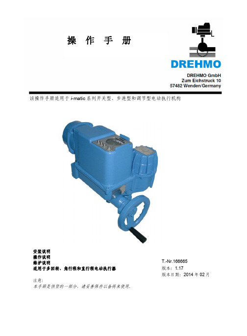
imatic电动执行器操作手册V1_17版
5
LEARN 模式......................................................................................................... 18
5.1 最重要的设定..................................................................................................................... 5.2 调整对比度........................................................................................................................ 5.3 如何设定语言..................................................................................................................... 5.4 LEARN 过程...................................................................................................................... 5.5 LEARN 菜单..................................................................................................................... 5.6 LEARN 过程最重要参数.................................................................................................... 5.7 LEARN 模式菜单结构和参数.............................................................................................
ICM2使用说明书

电动机在正常运行时,为了监视电机的运行状态及保护电机和线路的安全运行,需配 备: ● 电流表―测量电机的运行电流 ● 指示灯―监视电机的工作状态 ● 热继电器―防止电机长时间热过载运行 ● 其他…… 外部分列元件多,不但接线复杂,也浪费了安装空间
内部输出电源:24V,50mA,DC 起动完成后 OC 门导通(DC30V/100mA)
故障时
D11~D13 闭合 D12~D13 断开
共 18 页 第 6 页
ICM 软起动器说明书
输 D13
出
D14
D15
D16
模 拟 量 输 出
装置
电源
485A 485B Ma+ Ma-
L N FG
公共
触点容量 AC:10A/250V DC:10A/30V
电流上升到设定的限流值 l q ,然后保证输出电流在不 大于 lq 下,电压逐渐上升,电机加速,完成起动过程。 Lq 可在电机额定电流 le 的 0.5~4 倍间选择。
● 软停车(可选) 通过控制电压的下降时间,延长停车时间
以减轻停车过程中负载的移位或物体溢出。
四、 ICM 与传统降压起动器的比较
产品主要性 能
六、 基本接线图
共 18 页 第 5 页
ICM 软起动器说明书
QF
三相电源 380V/660V
R
U
S 操作键盘 V
T
W
电液执行机构巡检司机操作说明

电液执行机构巡检司机操作说明一、电液执行器结构及工作原理:电液翻板105、212、213主要结构由整体型电液推杆、外置式到位开关、安装架、溜槽翻板、控制箱组成。
工作原理是通过控制箱控制电机正、反转,驱动油泵向执行油缸前腔或后腔供油,在高压油的作用下,实现执行器推杆的伸出或缩回,同时通过连杆机构实现翻板的旋转,在行程限位开关的作用下实现前后两个位置。
101翻板由液压推杆、液压泵站、内置式行程开关、球型瓦座、安装架、溜槽翻板、控制箱组成。
工作原理是通过控制箱控制电机及换向阀,电机带动油泵将油箱中的油抽出加压后给换向阀,通过它控制执行机构拉杆的移动方向。
在现场可通过手动按钮和限位开关控制翻板位置,在调度室可通过上位机控制翻板位置。
204液动闸板由液压推杆、液压泵站、内置式行程开关、万向轴节、安装架、放煤闸板、控制箱组成。
工作原理是通过控制箱控制电机及换向阀,电机带动油泵将油箱中的油抽出加压后给换向阀,通过它控制执行机构拉杆的移动方向。
在现场可通过手动按钮和限位开关控制翻板位置,在调度室可通过上位机控制翻板位置。
二、操作规程:1、建立岗位司机日常维护制度,做好工作记录,便于日后检查维修。
岗位司机在进行操作前应详细阅读上一班设备运转记录本上记载的注意事项,在停机的情况下检查执行机构,确认无误后,方可进行试运转操作,并用眼、耳观察,如发现异常,应采取相应的处理措施。
2、加强集控系统与岗位司机间的联系,现场检查测试须在就地控制情况下进行,完好情况须及时向调度汇报。
3、集控操作最好参考位置反馈信号,采用宽范围跟踪,不能单纯找极限位置开关;特别是在双执行器同步操作时、振动较大时、垂直推动重物并要求液压自锁时,应尽量避免单纯跟踪极限位置开关。
因为此时的极限位置开关因受环境影响容易脱落,产生错误信号。
一旦出现不确定因素时应及时投入就地操作。
当出现过载和卡保护时,故障保护会动作,这时须将集控打到就地,由司机到现场去解决。
电液执行机构作业指导书
第一章电液执行机构作业指导书一、目的:帮助和指导班组有效处理电液执行机构故障,对存在的危险进行分析,并采取相应的安全措施进行规避,以确保作业安全和质量。
二、适用范围:各装置所使用的电液执行机构。
三、采用标准:以BDY9-BΙ型号为例。
四、工作原理:我厂所使用的电液执行机构大部分采用九江仪表厂生产的BDY9-BΙ型号。
当电气控制系统输入端接受4—20mA DC 输入信号,经I/V变换器隔离放大成0—10V DC主控信号,同时位移传感器测得现场实际阀位信号,经规格化处理转换成0—10V DC的反馈信号,二者在伺服放大器中比较得其差值经电压放大、功率放大后为±5V DC 的控制信号驱动射流管电液伺服阀,控制油缸的运动方向,通过机械连杆传动带动控制机构运动,直到主控信号和反馈信号之差值为零,这时伺服阀的控制电流也接近于零,伺服阀的阀芯处于中位,无液压油输出,油缸中的活塞停留在与输入信号相对应的位置上,实现输入信号和被控制设备的位移成线性关系,从而达到电液位置自动控制的目的。
图2-1.1 电液控制机构系统方框图五、作业步骤、危险分析、安全措施:接到工艺电话,首先立即赶赴主控室和现场,观察、询问故障现象,掌握第一手材料,然后通知车间相关技术人员和班长,到现场作JHA分析,并向工艺车间申请相关作业票,最后,待工艺监护人员和车间相关技术人员到现场时,才开始动手作业,其步骤如下:(表2-1.1)作业步骤危险分析安全措施1、要求工艺改液动或现场手摇控制。
没改液动或现场手摇控制,作业时会导致生产波动,甚至装置停工监督、指导、确认工艺改液动或现场手摇控制,注意勿要自己动手!输入信号4—20mA电气控制系统射流管阀伺服油缸控制设备位移传感器+-e2、根据故障现象,进行分析、判断、处理。
a、如果需要检查、更换电路板,必须先关掉仪表电源!带电检查、更换电路板,可能损坏电路板和母板在检查、更换电路板之前,务必确认先关掉仪表电源!b、如果需要检查、更换液压元件,必须先关掉油泵,并泄油压!并进行环保处理。
ICM2使用说明书

共 18 页 第 4 页
ICM 软起动器说明书
控制元件和控
16 位高性能单片计算机
继电器及普通电子元件
继电器
制方式
模糊控制
继电电子控制
继电控制
整机重量/体积
轻/小
较重/较大
重/大
外接电缆数量
6 根(3 进、3 出)
6 根或 9 根(130KW 以上为:3 进, 6 出)
KM D14
D15 D16
QF
ICM2软起动器
R S T U1 V1 W1 U V W
电动机
KM
旁路接触器
图 8-1-2 8-2 ICM 软起动器控制电路接线
ICM 系列电动机软起动器具有外部控制端子,为用户实现外部信号控制、远程控制及 系统控制提供方便。其中包括起动、停机、点动控制、故障输出(可作报警)、起动完成输出、 24V 直流电源输出、外配旁路接触器控制接口、4~20mA 直流输出等。如用户采用本机键 盘操作而不需远控或外部信号控制的情况下,这些端子无需接线(装置电源除外)。
二、 ICM 电动机软起动器工作原理
如图所示,电动机软起动器主要由电压检 测回路、电流检测回路、微处理器(CPU)、 存储器、可控硅(SCR)、触发回路、内置接触 器( JC )、显示器、操作键盘等部分组成。 其理论基础是数值分析、现代模糊控制理论 等。
电动机起动时,CPU 接受键盘输入命令, 检测电动机回路的可靠性,调用存储器予置 的数据, 控制SCR导通角, 以改变电动机输入电 压, 从而达到限制回路起动电流,保证电动机 平稳起动的目的。CPU 还通过内部检测回路, 判断电动机起动是否结束,当起动结束时,将 内置 JC 触点无流合上,电动机进入正常工作 状态。
电液联动执行机构操作流程

电液联动执行机构操作流程下载温馨提示:该文档是我店铺精心编制而成,希望大家下载以后,能够帮助大家解决实际的问题。
文档下载后可定制随意修改,请根据实际需要进行相应的调整和使用,谢谢!并且,本店铺为大家提供各种各样类型的实用资料,如教育随笔、日记赏析、句子摘抄、古诗大全、经典美文、话题作文、工作总结、词语解析、文案摘录、其他资料等等,如想了解不同资料格式和写法,敬请关注!Download tips: This document is carefully compiled by theeditor. I hope that after you download them,they can help yousolve practical problems. The document can be customized andmodified after downloading,please adjust and use it according toactual needs, thank you!In addition, our shop provides you with various types ofpractical materials,such as educational essays, diaryappreciation,sentence excerpts,ancient poems,classic articles,topic composition,work summary,word parsing,copy excerpts,other materials and so on,want to know different data formats andwriting methods,please pay attention!《电液联动执行机构操作流程》一、准备工作阶段1. 确定操作目的:明确电液联动执行机构的操作目的,例如开启或关闭阀门、调节流量等。
MLB MLD MLC ML系列执行器说明书

37.2
16.0
2X MOUNTING HOLES M5X0.8 7mm
A 15.5
13.8
SHAFT ONLY
6.7 6.0
5.2 DETAIL A
(1) EXTERNAL LINEAR GUIDE
45.5
(2) EXTERNAL LINEAR GUIDE
58.0
DOVETAILS
14.3
2.0
2X 60°
1.0
TYP
7.6
5.2
TYP
TYP
45°
TYP
21.9
DOVETAIL SLOTS
CARRIAGE ONLY
T-SLOTS 29.3
DOVETAIL SLOTS
NO DOVETAIL
31.4
39.3
39.3
WITH
DOVETAIL
AVAILABLE IN LEFT OR RIGHT SIDE MOUNT
0.06
0.13
Add for 100 mm of stroke Total Carriage Mass
0.15
0.34
Kg
lbf
0.020
0.044
Total Carriage Mass & Top Plate
0.059
Coefficient of Friction
0.19
Max. Speed
m/s 1.9 in/s
0.130
75 25.6 0.2 0.375
0.50 0.94 0.062
0.15 0.30
0.25 0
.0006
LOAD RANGE
80% CRITICAL SPEED
EI集成式电动执行器(ICM)

EI集成式电动执行器(ICM) 使用手册目录1. 注意事项2. 概要3. 特性4. 参数5. PCB 平面布置图6. LOCAL / REMOTE(现场/远程) 运行方法7. 故障查处1.注意事项1)务必确认所加电源是否与设备一致。
2)雨天有触电危险,勿进行接线操作。
3)所有接线操作务必确认电源断开后再进行。
4)要使用的电源为3相时,注意不要发生逆相及缺相。
5)为了提高本设备的性能,可能不经事先通报而变更。
2.概要1)集成式支持现场运行方式和在远程控制运行方式。
2)集成式单相与三相都支持,主电源为三相时,可以另外装PCM使用。
3)3相接线时,集成式装上8位MPU,检查逆相及缺相,可靠性高。
4)带有相保护功能,发生逆相及缺相时,防止电机逆向运行。
3.特性1)可以现场/远程,手动/自动远程控制。
2)电源及输入输出回路分离,保护回路。
3)选择点动/连续方式,用于脉冲及连续信号。
4)选择自动方式,可以使用比例调节功能(RPC:选项)。
4.参数1)主电源2)三相 : 380VAC~480VAC3)单相 : 110VAC / 220VAC4)内部使用电源5)控制: 24VDC, 5VDC6)加热器(选项): 220VAC7)功耗: 5VA8)使用温度: -20℃~60℃9)使用湿度 : 90% MAX10)方式: 现场 / 远程 (自动 / 手动)11)点动方式/连续方式(ICM Dip开关)5.PCB平面布置图1) ICM(Integral Control Unit)A.J2(MOTOR):单相时连接电机(3相时不用)。
B.J4(AC_IN):220VAC输入。
C.J5(AC_OUT):220VAC输出。
D.J6(EX_OUT):输出接点,输出控制信号,与PCM的“P (J4 : SIG IN)” 端子连接(只用于3相)。
E.J10(LM_SW):与关闭、打开、关闭扭矩及打开扭矩的限位开关连接。
F.J11(DC_POWER):与变压器的次级连接。
电动执行器操作手册
电液联动执行机构操作流程
电液联动执行机构操作流程Operating an electro-hydraulic actuator requires a thorough understanding of its mechanisms and proper procedures. As such, it is crucial to follow a strict set of guidelines to ensure the safety and efficiency of the operation. When using an electro-hydraulic actuator, it is imperative to first check that all connections are secure and that the system is free of any leaks. Once these preliminary checks have been completed, you can proceed with the operation, keeping in mind the importance of monitoring the pressure and flow rates throughout the process.使用电液联动执行机构需要对其机制和操作流程有深入的了解。
因此,遵循一套严格的指导原则以确保操作的安全性和效率至关重要。
在使用电液联动执行机构时,首先要检查所有连接是否牢固,系统是否没有任何泄漏。
一旦完成这些初步检查,您可以继续操作,牢记在整个过程中监测压力和流量的重要性。
One of the key steps in operating an electro-hydraulic actuator is to properly set the desired position or movement. This can be done through adjusting the control valves and fine-tuning the system toachieve the desired outcome. It is important to be patient and precise during this step, as any errors in positioning can lead to malfunctions or accidents. Additionally, it is crucial to follow the manufacturer's guidelines when setting the position to ensure the actuator functions correctly and efficiently.操作电液联动执行机构的关键步骤之一是正确设置所需的位置或运动。
电液执行机构讲义

电 液 执 行 机 构
LBHF电液执行机构部分 5) 伺服阀 BD系列电液伺服阀是美国PARKER 公司设计制造的一种抗污染型电液伺服阀, 专门适用于条件恶劣的工业场合。由力矩 马达、偏转板射流放大器和滑阀组成。其 前置级采用偏转板射流放大器,前置级最 小流通缝隙尺寸是其它型号司服阀前置级 最小流通缝隙的20倍,这就减少了在工作 中前置级因油液被污染而堵塞的可能性, 从而大大提高了BD阀的可靠性。BD阀的 输出级是油在中间位置时全部关闭的四凸 肩滑阀副组成,它的特点是滑阀阀套上开 有四组矩形孔,阀芯的工作边缘在工作时 准确地与阀套上的矩形孔边缘匹配,以便 提供与输入电信号成线性关系的流量。
LBHF电液执行机构部分
电 液 执 行 机 构
LBHF电液执行机构部分
电 液 执 行 机 构
电 液 执 行 机 构
LBHF电液执行机构部分 PS1 压力继电器,当泵出口压力低 于设定值时,提供PAL报警,常开 触点。 PDS1 压差发讯器,当滤油器进出 口压差超过极限值0.35MPa时,提供 滤油器差压高报警,常开触点。 PI1 压力表,指示泵出口压力。 PI2 压力表,指示辅助蓄能器A1的 压力。 A1 辅助蓄能器,吸收液压系统压 力脉动,补充系统工作油液,容量 16升。
电 液 执 行 机 构
电 液 执 行 机 构
LBHF电液执行机构部分 CV1、CV1' 单向元件,防止压力 油倒流至变量泵P1、P2。 CV2、CV2' 插入式单向阀,防止 压力油倒流回滤油器FT2、FT2 MV1、MV1' 插入式截止阀,双联 过滤器切换操作用,与CV2、 CV2'共同截止油路,需要更换FT2、 FT2'滤芯时使用。 FT2、FT2' 双联过滤器,一组操 作时另一组备用或同时使用,用 MV1、MV1'可实现切换操作。在 系统正常运行过程中,可实现不停 机滤芯更换。 RV1 溢流阀,限定系统最高压力, 超压时开启卸荷
执行机构工作原理及使用方法
特点:电路结构简单,但串联R2消耗能量降低放大功率;电感较大使电路对脉冲反应较慢,输出波形差。主要用于转速要求不高的小型步进电机控制。
3.电流检测型驱动
图2-28 电流检测驱动电路原理
恒流斩波驱动
(a)恒流斩波驱动电路 (b)电路波形图2-29恒流斩波驱动电路
4.细分驱动
设备难于小型化;液压源和液压油要求严格;易产生泄露而污染环境。
机电一体化系统对执行元件的基本要求
(1)惯量小,动力大。 (2)体积小,重量轻。 (3)安装方便、便于维修维护。 (4)易于实现自动化控制。 2.3 电动执行机构 常用电动执行机构 : DC/AC电动机、力矩电动机、步进(脉冲)电动机、变频调速电动机、开关电磁电动机以及其他电动机(直流或交流脉宽调速电动机、电磁伸缩元件)等。
1—换向极铁心;2—换向极绕组
图2-6 直流电机电刷装置
1—电刷;2—刷握;3—弹簧压板; 4—座圈;5—刷杆
电刷与换向器配合可以把转动的电枢绕组电路和外电路连接并把电枢绕组中的交流量转变成电刷端的直流量。电刷装置由电刷、刷握、刷杆、刷杆架、弹簧、铜辫构成,如图所示。电刷组的个数,一般等于主磁极的个数。
气压式
气体压力源压力5~7×Mpa;要求操作人员技术熟练。
气源方便、成本低;无泄露而污染环境;速度快、操作简便。
功率小、体积大、难于小型化;动作不平稳、远距离传输困难;噪音大;难于伺服。
液压式
液体压力源压力20~80×Mpa;要求操作人员技术熟练。
输出功率大,速度快、动作平稳,可实现定位伺服控制;易与计算机(CPU)连接。
2.2 执行元件的种类及性能
种类
特点
优点
缺点
电气式
电控液动执行机构说明书

一、概况:本单位对选煤厂原煤车间进行改造的是:204仓下14台放料直闸板和101大型分流翻板。
采用电控液动执行器(ZL96246578.X)、电控液动执行机构(ZL97218944.0)、电控液动执行装置(ZL00255460.X)等三项国家专利技术,设计采用如下所示的全内置式电控液动执行机构,并负责安装与调试工作。
通过对现场的多次实际观测,发现现场环境恶劣。
为达到选煤厂最终实现“减人增效”的目的,必须使用全内置式电控液动执行机构。
为满足现场要求,控制箱体由具有相应资质的唐山电器厂设计制造;液压油缸等由具有相应资质的唐山三通液压气动制造公司制造。
所谓全内置式电控液动执行机构,就是将反映被控对象所在位置的位移传感器和对运行终端位置进行控制的限位开关都放入执行机构内,这样反馈信号和限位开关受环境影响极小,维护量也小,还提高了纳入集控系统的可靠性。
由于使用远距离全程信号跟踪显示,这样在集控室就能知道设备运行情况,并且还能根据各种保护信号对设备运行状况进行判断,不用人工直接到现场就能对设备进行控制,并能知道设备运行状况。
二、控制101翻板用电控液动执行机构的设计与安装使用说明:1、设计说明:对于101设备,经过反复论证认为最好使用一台行程为1960mm的大型电控液动执行机构对该大翻板进行驱动,该设备正常工作时所需力量不到2吨,而在冬天等特殊场合,需驱动力较大,现场目前使用5吨电动绞车运转正常。
根据这些特点,所设计出的执行机构额定出力至少应在2吨以上,最大出力也应在5吨以上。
另外,由于101设备是倾斜安装的,加之翻板为弧线运动,这就是通常所说的二维空间运动,安装难度极大。
必须设计一个能转动灵活的支撑座,各连接件也必须转动灵活,同时要求承受能力必须大于10吨。
根据该设备实际情况,设计出支撑座采用能三维运动的球型轴瓦方式,它不仅能使执行机构转动灵活,还能缓解执行机构径向受力,连接件采用万向轴节。
图(一)为安装示意图:具体技术参数如下:执行机构行程: 1960mm 执行机构缸径:φ100mm(内径)拉杆直径:φ65mm 驱动电机型号:YDF231-4(0.75KW)电机额定电流: 2.6A 电机额定电压:~380V电机防护等级: IP44 齿轮泵型号:CBWS-E310齿轮泵额定压力:16MP 执行机构额定工作压力:约5MP执行器额定出力:23KN~40KN 执行器最大出力: 80KN左右执行器运行时间:40秒~76秒执行器工作介质:46号耐磨液压油2、使用说明:执行机构简易原理图和主要功能如下:1执行机构2齿轮泵3阀门电机4油箱5换向阀6信号板7出线嘴8油管9连接件10支架11传感器和行程开关其工作原理是:油泵将油箱中的油抽出加压后给换向阀,通过它控制执行机构拉杆的移动方向。
AIMI说明书

目 录一、概述 (1)二、主要技术参数 (2)三、型号规格 (3)四、执行机构外形及安装尺寸 (7)五、执行机构的接线 (15)六、开箱和产品的陈套性 (20)七、运输和贮存 (20)八、质量承诺 (20)一、概述AI、MI系列智能型电动执行机构是在引进产品ROTORK A、M系列电动执行机构的基础上,采用当今最先进的超大规模数字集成电路研制而成的新一代智能化、数字化、中/英文菜单显示、遥控操作的电动执行机构。
使用红外线遥控器可安全、快捷地对执行机构力矩值、限位以及其它所有控制、指示和保护功能进行设定。
本产品执行的标准代号及名称:Q/YXBM 233 -2004《ID系列智能型电动执行机构》。
1、AI、MI智能型电动执行机构的主要特点:经典的机械力矩传感器,性能稳定、工作可靠脉冲数字化的霍尔效应位移传感器精度等级高,适应性强采用超大规模的集成芯片,使执行机构具备了强大的功能提供中文、英文切换菜单。
菜单式操作,凸现了调试简单、操作方便的优点非侵入式设计——采用双密封结构、无贯通轴设计,无需打开电气端盖即可通过遥控器进行设定和调试,是防护等级IP68的绝对保证2、AI、MI智能型电动执行机构的功能:遥控器设定功能执行机构阀位指示显示功能行程限位保护功能力矩限位保护功能状态指示触点功能1)中途限位 4)执行器正在运行 7)远程控制 10)手轮操作中 13)行程中力矩跳断 2)执行器正在打开 5)就地停止 8)开阀联锁 11)开阀力矩跳断3)执行器正在关闭 6)就地控制 9)关阀联锁 12)关阀力矩跳断阀门报警功能控制系统报警指示1)过力矩报警功能 2)堵转报警功能 a 、关方向过力矩 a 、关方向堵转 b 、开方向过力矩 b 、开方向堵转 c 、全方向过力矩 c 、全方向堵转1)紧急事件(ESD)报警 2)断信号报警执行机构报警指示1)电机过热报警 3)内电源故障报警 5)内部系统故障报警 7)就地接线故障报警 2)电池电量过低报警 4)电源缺相报警 6)阀位信号掉失保护 瞬间反向保护功能就地控制电动/自保持选择功能触点方式选择功能外部联锁设置功能条件控制设置功能两线控制设置功能力矩旁路设置功能ESD超越保护功能中断设置功能附加指示触点功能3、AI、MI智能型电动执行机构的工作原理:AI、MI系列多转式智能型电动执行机构由三相异步电动机驱动,通过蜗轮蜗杆减速,带动空心输出轴转动输出转矩。
ICM A5 电压计测试器说明书

Instruction ManualICM A5Clamp MeterEN DE ES IT FRSafety InformationRead and understand this Instruction Manual completely before using this instrument. Failure to observe the warnings and cautions in this Instruction Manual may result in injury or death, or damage to the instrument and other equipment or property.If this instrument is used in a manner not specified in these instructions, the protec-tion provided by the instrument may be impaired.WARNING- Examine the instrument and probes and leads before use. Do not use the instru- ment if it is wet or damaged, or if yoususpect it is not operating correctly.- When using the instrument, test leads or probes, keep your fingers behind thefinger guards.- Remove the test lead from the instrument before opening the battery cover or instru- ment case.- Always use the correct terminals, switch position and range for measurements.- Verify the instrument is operating correctly by measuring a known voltage beforeuse. If in doubt, have the instrumentserviced.- Do not apply more than the rated voltage as marked on the instrument betweenterminals, or between any terminal andearth ground.- Use caution when measuring voltagesabove 30 Vac rms or 60 Vdc. Thesevoltages pose a shock hazard.- To avoid incorrect readings that can lead to electric shock, replace the battery assoon as low battery indicator appears in the display.- Disconnect the circuit power anddischarge all high-voltage capacitorsbefore making resistance, continuity, ordiode measurements.EN - 2EN - 3MaintenanceDo not attempt to repair this Instrument. It contains no user-serviceable parts. Repair or servicing should only be performed by qualified personnel. This instrument should be calibrated yearly, or more frequently if used in harsh conditions or if it is suspected of being inaccurate.For calibration and repair contact RS Components - the address is given at the end of these instructions.CleaningPeriodically wipe the case with a damp cloth and detergent. Do not use abrasives or solvents.EN - 4Auto Power OffThe instrument will automatically turn off approximately 10 minutes after the last operation.EN - 51. The VoltSense function will operateirrespective of the position of thefunction rotary switch, including theOFF position.2. Remove the test leads from theinstrument as they are not used for the VoltSense test.3. Press and hold the VoltSense button. The LCD display will go blank, a tone will sound and the red LED will illuminate momentarily to confirm the instrument is operational.EN - 6EN - 7ResistanceACAEN - 8Battery ReplacementWhen the low battery indicator "<" appears on the LCD, replace the batteries with the type given in the specifications.WARNING Disconnect the test leads from the circuit and the instrument before removing the battery cover.Refer to the following figure to replace the batteries:EN - 9Specifications1-1 General SpecificationsLCD display :31/2 digit large scale LCD readout.Display resolution : 2000 counts. Measuring rate : 1.5 times / sec. Overrange display :“OL” is displayed for “Ω” functions,The real value is shown for the “A” and “V” functions.Automatic power off time : Approximately 10 minutes after power on. Low battery indicator : <is displayed. Power requirement : 1.5V x 2 batteries Battery life : Approximately 250 hours with Alkaline batteries.1-2 Environmental ConditionsIndoor use only.Calibration : One year calibration cycle. Operating temperature :0°C to 30°C (32°F to 86°F) @ ≦80% RH 30°C to 40°C (86°F to104°F) @≦75% RH) 40°C to 50°C (104°F to 122°F) ≦45%RH Storage temperature : -20 to + 60°C(-4°F to 140°F) @ 0 to 80% RH with batteries removed from the instrument. Dimensions (W x H x D) :54mm x 193mm x 31mmWeight: 280g including battery. Accessories: Battery (installed), Carrying case and User manual.Measurement Category (Installation Category) :per IEC 61010-1:2001: CAT.Ⅲ1000V. CAT.Ⅳ 600V. Pollution Degree 2 Measurement Category l is for measure- ments performed on circuits not directly connected to mains. Examples include : Measurements on battery powered equip- ment and specially protected (internal) mains-derived circuits.EN - 10Measurement Category ll is for measure-ments on circuits directly connected to the low voltage installation. Examples include: Household appliances, portable tools and similar equipment.Measurement Category lll is for measure-ments performed in the building installation. Examples include measurements on distribution boards, junction boxes, socket- outlets and wiring and cables in the fixed installation.Measurement Category lV is for measure-ments performed at the source of thelow-voltage installation. Examples include measurements on primary overcurrent protection devices and electricity meters. Operating altitude : 2000m (6562 ft) Conductor Size : 16mm diameter. Pollution degree : 2EMC : EN 61326-1Shock vibration: Sinusoidal vibration per MIL-T-28800E (5 to 55 Hz, 3g maximum). Drop Protection : 1 metre drop onto hardwood or concrete floor.EN - 111-3 Electrical Specifications Accuracy is ±(% reading + number of digits) at 23°C (73.4°F) ± 5°C (± 9°F)< 80%RH.Temperature coefficient :Add 0.2 x (Specified accuracy) / °C (1.8°F), < 18°C > 28°C (< 64.4°F >82.4°F).DC / AC VoltsEN - 12* For 0.4V ~ 0.8VMax.Test Current : 1.5mAMax. Open Circuit Voltage : 3V Overload Protection : 600Vrms Continuity : Internal beeper activates if the resistance of the circuit under test is less than 50Ω. It will then turn off if the resistance is increased beyond 250Ω. Response time is approximately 0.25~1 sec.EN - 13Limited WarrantyThis instrument is warranted to the original purchaser against defects in material and workmanship for 3 year from the date of purchase. During this warranty period, RS Components will, at its option, replace or repair the defective unit, subject to verifica-tion of the defect or malfunction. This warranty does not cover disposable batteries, or damage from abuse, neglect, accident, unauthorized repair, alteration, contamination, or abnormal conditions of operation or handling.Any implied warranties arising out of the sale of this product, including but not lim-ited to implied warranties of merchantability and fitness for a particular purpose, are limited to the above. RS Components shall not be liable for loss of use of the instru-ment or other incidental or consequential damages, expenses, or economic loss, or for any claim or claims for such damage, expense or economic loss. Some states or countries laws vary, so the above limita-tions or exclusions may not apply to you. For full terms and conditions, refer to the current RS Catalogue.EN - 14EN - 15EN - 16AfricaRS Components SAP.O. Box 12182,Vorna Valley, 168620 Indianapolis Street,Kyalami Business Park, Kyalami, MidrandSouth AfricaAsiaRS Components Pte Ltd.31 Tech Park Crescent Singapore 638040ChinaRS Components Ltd.Suite 23 A-CEast Sea Business CentrePhase 2No. 618 Yan'an Eastern Road Shanghai, 200001ChinaEuropeRS Components Ltd.PO Box 99, Corby,Northants. NN17 9RSUnited KingdomJapanRS Components Ltd.West Tower (12th Floor), Yokohama Business Park,134 Godocho, Hodogaya, Yokohama, Kanagawa 240-0005 JapanU.S.AAllied Electronics7151 Jack Newell Blvd. S.Fort Worth, Texas 76118U.S.A.South AmericaRS Componentes LimitadaAv. Pdte. Eduardo Frei M. 6001-71 Centro Empresas El Cortijo Conchali, Santiago, Chile 。
- 1、下载文档前请自行甄别文档内容的完整性,平台不提供额外的编辑、内容补充、找答案等附加服务。
- 2、"仅部分预览"的文档,不可在线预览部分如存在完整性等问题,可反馈申请退款(可完整预览的文档不适用该条件!)。
- 3、如文档侵犯您的权益,请联系客服反馈,我们会尽快为您处理(人工客服工作时间:9:00-18:30)。
1
LBZN/ICM 电液执行机构使用说明书 V1.0
6.3. 查看报警信息..................................................................................................... 16 7. 用户登录 ....................................................................................................................... 19 8. 本地调节 ....................................................................................................................... 20 9. 泵序选择 ....................................................................................................................... 21 10. 泵启停 ........................................................................................................................... 21 11. 强制起泵 ....................................................................................................................... 22 12. 本地点动操作 ............................................................................................................... 22 13. 机械手动操作 ............................................................................................................... 23 14. 其它操作方法 ............................................................................................................... 24
第三部分 基本操作 .................................................................................................................... 14 6. 查看运行状态 ............................................................................................................... 15 6.1. 综合信息显示..................................................................................................... 15 6.2. 阀位显示页面和报警页面................................................................................. 16
LBZN/ICM 电液执行机构 使用说明书
用户:恩贾梅纳炼油厂 型号:LBZN/ICM
兰州石化公司机械厂 北京林克富华技术开发有限公司
2010 年 4 月
LBZN/ICM 电液执行机构使用说明书 V1.0
目
录
第一部分 产品描述 ...................................................................................................................... 1 1. 产品结构 ......................................................................................................................... 3 2. 技术规格 ......................................................................................................................... 5 2.1. 技术指标............................................................................................................... 5 2.2. 工作参数............................................................................................................... 5 3. 工作原理 ......................................................................................................................... 6 3.1. 压力控制功能....................................................................................................... 8 3.2. 阀位的调节控制................................................................................................... 9 3.3. 阀位的锁位........................................................................................................... 9 3.4. 阀位的点动控制................................................................................................... 9 3.5. 阀位的手动控制................................................................................................. 10 3.6. 自保逻辑............................................................................................................. 10
14.1. 系统卸压............................................................................................................. 24 14.2. 溢流压力设定..................................................................................................... 24 14.3. 高压油滤滤芯更换............................................................................................. 24 14.4. 蓄能器测压与充气............................................................................................. 25 14.5. 加注液压油......................................................................................................... 25 14.6. 更换 iSA 控制器 ................................................................................................ 26 第四部分 仪表调校 .................................................................................................................... 27 15. 信号校准 .......................................................................................... 28 16. 阀位校准 ....................................................................................................................... 29 17. 阀位回讯校准 ............................................................................................................... 30 18. 备用回讯的选择与校准 ............................................................................................... 31 19. 自保信号 ....................................................................................................................... 32 20. 自保位置与缓冲量 ....................................................................................................... 33 21. 跟踪丢失 ....................................................................................................................... 34 22. 泵模式 ........................................................................................................................... 35 23. PID 设置 ....................................................................................................................... 35 24. 报警通道设置 ............................................................................................................... 36 25. 锁位项目 ....................................................................................................................... 37 26. 偏差归零 ....................................................................................................................... 38
