德国沃纳worner脉动阻尼器说明书
脉冲阻尼器使用说明书

脉动阻尼器使用说明
一、概述
脉动阻尼器又名脉动缓冲器,是消除管路脉动的常用元件,是计量泵必须配备的附件。
脉动阻尼器能够平滑由柱塞泵、隔膜泵等容积泵引起的管路脉动和系统的水锤现象。
它由耐腐蚀的隔膜将气体与管路中的液体隔离,通过气室容积的变化平滑管路脉动。
二、主要功能
1.允许系统使用更小的管径,降低成本。
2.保护管路、弯头、接头不受压力波动的冲击。
3.减小除去水锤对系统的危害。
4.降低系统的能耗。
5.减小流速波动的峰值。
6.为计量泵创造良好的工作环境并改善泵的工作性能。
7.和背压阀等配合使用可以使管路的压力波动接近为零。
三、工作原理
根据玻意耳定律P1V1=P2V2,通过改过气体的体积来平滑管路脉动。
对于流速有正弦曲线特性的系统,波峰时,气室体积变小,脉动阻尼器吸收多余的流量的液体,波谷时,气室体积变大,释放存储的液体,从而达到平滑脉动的效果。
四、产品特点
1.可以预充气体,充气后平滑脉动的效果比空气室式脉动阻尼器的效果好。
2.气体不与管路液体接触;气体不会因溶解到液体里而损失。
3.设有限位装置,防止膜片过度变形。
五、脉动阻尼器的使用
1.使用时压力表指针应小幅摆动,摆动过大则说明预充气体压力偏小或者选型偏小,不。
德国威纳泵装置手册(Woerner pump unit manual)

Leaflet-No.0704.12.11 EN Replaces No.0704.09.11 ENPage 1 of 10Pump unit GMG-B Pump unit GMG-BUse:As pump unit in central lubrication systemsTechnical data:Admissibledelivery pressure:at max.250barNumber of pump elements:at max.2Delivery volume per stroke and elementwith pump element 04:0,04cm³with pump element 08:0,08cm³with pump element 16:0,16cm³Temperature range:-20...+60°C At low temperatures,grease pene-tration needs to be observed.Mounting position:verticallyMaterialCasing:Aluminium Pump element:Steel Reservoir:St /Polyamide transparent Gaskets:NBR (Perbunane)Medium:Oil and grease up to NLGI class 2(Mind conditions of use of both the reservoir and filling level monitoring device!)Drive (without control unit):Mains voltage:24VDC Current at max.:2,5A Speed(load-dependent):approx.30min System of protection:IP55for control unit Current:-1+++++for the delivery of oil,liquid grease orgrease1or 2pump outletsup to 20outlets with progressivedistributor flanged-onelectric control and monitoring with function stirring without deli-very higher IP on requestDepending on type of construction,the DC gear motor should only be used in pulse mode.For other modes of operation,three-phase current motors are of advantage (e.g.Pump unit GMA-C)Power pack (.):min.3,0A Voltage:24V ±10%DCEUGEN WOERNERGmbH & Co. KGPostfach 1661DE-97866 Wertheim Hafenstrasse 2DE-97877 Wertheim Tel.+49 (0) 9342 803-0Fax.+49 (0) 9342 803-202www.woerner.deinfo@woerner.de - S u b j e c t t o m o d i f i c a t i o n s -Leaflet-No.0704 ENPage 2 of 10Description:Drive:54Delivery function:32.11Function stirring without delivery:33The pump unit GMG-B is driven by a gear motor flanged to the pump casing from downside.When the eccentric shaft rotates,the dlivery piston of every pump element makes a suction and delivery stroke per rotation each,whilst delivering lubricant from the reservoir to the lubrication points...GMG-B ....Pump elements:suction stroke 2.2 2.1312.32.4delivery stroke 32.12.32.42.5 2.6R At ,the pressure spring moves the delivery piston against the eccentric shaft .Concurrently,the lubricant available in the reservoir is drawn through the suction hole into the metering chamber .At ,the eccentric shaft shifts the delivery piston .At the same time,the suction hole is closed up and the lubricant volume available in the metering chamber delivered through the check valve to the outlet .Marking the pumpe elements:Size:Delivery volume:Marking :040,04cm³white ring 080,08cm³without ring 160,16cm³black ringDepending on the case of operation (lubricant,lubricant requirement,etc.),the pump unit can be fitted with different pump elements,reservoirs,and monitoring elements In some modes of operation,improvement of lubricant quality and delivery behaviour requires the lubricant to be stirred additionally Such stirring is facilitated in the pump by means of a specifi-cally designed eccentric drive When the eccentric shaft rotates into the one direction of rotation,the pump ele-ments are operating while the stirring device supplies them with the lubricant As soon as the eccentric shaft starts to rotate into the other direction,the lubricant is stirred without any delivery operation by the pump elements taking place The integrated control unit allows operating and off-duty periods for both the delivery with and without stirring to be programmed independently from each other unit EUGEN WOERNER GmbH & Co. KGPostfach 1661DE-97866 Wertheim Tel.+49 (0) 9342 803-0Fax.+49 (0) 9342 803-202www.woerner.deHafenstrasse 2DE-97877 Wertheim info@woerner.de - Subject to modifications -Leaflet-No.0704 ENPage 3 of 10Technical data:Temperature range:0...+60°CSwitching voltage at max.:30VDC Switching current at max.:0,25A Switching power at max.:3,0W Contact function:Opener For inductive and capacitive loads protec-tive circuits (diode,RC-member,varistor)have to be provided for.Level control "F":min.level monitoring for oilThe level control "F"consists of a float that is lifted in the oil.If oil falls below minimum filling level,the contact opened.Note:The PUR float is suited for mineral oils only.In case of other media,their compatibility needs to be checked.Notes on operation:The pump unit must be operated with clean oil or grease from original packages only.During start-up,the pump has initially to be filled with gear oil up to stirring blade level.Thus,proper venting is ensured.The lines to the lubrication points must be clean andhave free throughput.They shall not be connected to the lub-rication points unless the lubricant comes out free of bubbles.All connectors of the delivery line have to be checked for leakage.To protect the pump unit and the lines connected from overload,protec-tive elements such as pressure control valves have to be integrated basically.Level control:Level control "C":min.level monitoring for liquid grease NLGI-class 000up to grease NLGI-class 2.Version without control:In case of empty reservoir and rotating pump drive shaft,the contact is switched.(approx.5seconds).When "stirring without delivery",signal evaluation has to be suppressed.The "Empty"signal is intermittent The switching mechanism may shift as for instance during reservoir filling.In case of external control,signal evaluation must therefore be delayed when the pump is switched onFilling connector "W"Closing nippleFilling connector:This part is located beneath the left-side pump element.Filling connector "A"1)Cone lubricator nipple DIN 71412 -AG1/4WFilling connector "C"1)Flat lubricator nipple DIN 3404 - M22Filling connector "G"Closing nippleG 1)not for oil suitablyAccessory for filling connector "G" and "W":Quick release coupling 954.002-09(p = 35 bar)max G 1/4Leaflet-No.0704 ENPage 4 of 10other reservoir versions available on requestCapacity[l]2Polyamide translucent PolypropylenePolypropylene4Reservoir "2"Reservoir 4P""MaterialLid Reservoir Polyamide translucent Reservoir "7"7Stainless steelStainless steelEUGEN WOERNER GmbH & Co. KGPostfach 1661DE-97866 Wertheim Tel.+49 (0) 9342 803-0Fax.+49 (0) 9342 803-202www.woerner.deHafenstrasse 2DE-97877 Wertheim info@woerner.de - Subject to modifications -Leaflet-No.0704 ENPage 5 of 10At the right-side pump element,progressive distributors of theVPB type can be flanged on directly.As much as 20lubrication points with different distribution volumes are possible.A selection of progressive distri-butors can be chosen by means of the GMG-B purchase-designation.By monitoring the movement of one distri-butor piston,the lubricant allocation to all outlets is monitored.Evaluation through the pump control unit requires selection of a progressive distributor fitted with the func-tion control In case of oil,metering accuracy depends on viscosity,flow resistance at the outlets,and delivery speed.Functionality:Function control:Technical data progressive distributor:The lubricant supplied by the pump element is delivered to the outlet progressively (i.e.progressing in the distributor).RK.Metering volume per cycleand outlet:0,20cm³Lubrication point connectors:4,6or 8other versions available on request (up to 20lubrication points)Operating pressure at max.:150barDelivery mediumOil-viscosity:as of approx.140cP(equals ISO VG46at 20°C)Grease up to:NLGI class 2MaterialOuter body:AluminiumInner parts:Steel Additional information on VPB-G:Leaflet-no.:0177on VPB-B:Leaflet-no.:0378Switching voltage:10...36VUCSwitching current at max.:25mA Switching power at max.:0,9VA Ambient temperature:0...60°C Material (casing):PA or 1.4305Function control RK:Distributor variants :(VPB-G)4outletswithout function checking device "P4"with function checking device RK "P5"6outletswithout function checking device "P0"with function checking device RK "P1"8outletswithout function checking device "P2"with function checking device RK "P3"Note on operation:Note:N The 0,16cm³delivery volume pump element is marked by means of a grey plastic pimple .Upon start-up,both pump element and progressive distributor need to be vented.The lubricant must come out free of bubbles from all outlets.At first,the connecting case should be vented at venting screw or at the built-in pressure control valve.Then,the progres-sive distributor should be vented.6Auxiliaries:Pressure control valve at the pro-gressive distributor:Opening pressure:Purchase-no.:70bar 110.566-65150bar110.564-65Customised setting:50...150bar110.568-65For delimitation of the maximum operating pressure,pressure control valves instead of the venting screw can be screwed in.76Flanged progressive distributor:6N7EUGEN WOERNERGmbH & Co. KGPostfach 1661DE-97866 Wertheim Tel.+49 (0) 9342 803-0Fax.+49 (0) 9342 803-202www.woerner.deHafenstrasse 2DE-97877 Wertheim info@woerner.de - S u b j e c t t o m o d i f i c a t i o n s -Leaflet-No.0704 ENPage 6 of 10The control unit serves to monitor and trigger the pump aggregate.It is capable of switching the pump on and off depending on time and load.Besides,the control unit can be used to monitor the filling level and functionality of the progressive distributor In case of failure,a corresponding message can be made accessible to a higher ranking system The control unit must be started via an external E1=Motor overloadedE2=Progressive distributor faulty E3=Level faultFault messages can be deleted by keeping the SAVE key depressed for a while.Fault Description:.."release".""Control variant "C":Control without distributor monitoringControl variant "C1":Control with distributor monitoring for pro-gressive distributor flanged onControl variant "C2":Control with distributor monitoring for ex-ternally mounted progressive distributor (with functional checking device "RS").For connecting cable see "Auxiliaries"page 7Control unitControl unit operation:1.Menu call-up:By long pressing the "MODE"key,the menu structure is called up.2.:""3.Changing of values:""""""""Navigation within the menus By keeping the Mode key depressed another time,the menu items P1…P11can be selected successively.The SELECT key can be used to change setting values and functions.In case of time data,short pressing of the SELECT key results in a shifting by +1,whereas any longer pressing will result in a shifting by +20.When the SAVE key is depressed for a while,the set values will be saved.Pres-sing the MODE key enables the next menu item to be accessed without any saving action.4.::"""".5.:""""Special Functions Specific lube delivery When the SELECT key is depressed in the operating mode ON for a while,pum-ping action will be carried out for 60seconds Test Mode By pressing the keys SAVE and MODE quickly in one go and in the order mentio-ned,a pump test mode will be invoked (the keys have to be kept depressed for 0,5seconds at least).In this mode,a pumping process will be actuated for 10seconds.Thereafter,the pump continues to stir for another 5seconds.6.Change of password starting from soft-ware version 2.52:1.Press Save +Select +Mode2.Keep keys depressedand switch voltage on 3.Enter current password(factory default: 1234)4.Save by pressing Save 5.Enter new password 6.Save by pressing Save 7.The program will change intonormal mode If the newly changed password gets lost,the control unit can be reset to the original parameters in the factory.This,however,will result in loosening all changes made.For that reason,all changes made to the parameters should always be recorded and archived.""""""""""EUGEN WOERNER GmbH & Co. KGPostfach 1661DE-97866 Wertheim Tel.+49 (0) 9342 803-0Fax.+49 (0) 9342 803-202www.woerner.deHafenstrasse 2DE-97877 Wertheim info@woerner.de - Subject to modifications -Leaflet-No.0704 ENPage 7 of 10Connection diagram for the control C version""Electric connection 8:Explanation:Equipotential bonding 9:Connection type:Connector socket5-pin (M12)Version with control unit:1-+24VDC2-+24VDC (external release)3-0V4-Alarm output Version without control unit:1-+24VDC (delivery function)2-+24VDC (stirring function)3-0V4-Level monitoringDelivery function:24V to Pin 1Stirring function:24V to Pin 1and 2Threaded hole:M41)1)1)Stirring function active when PIN2is actuated.1432Auxiliaries Cable jack for electric connection:913.404-65913.405-07Connecting cable for externally moun-ted progressive distributor:913.405-23913.405-06:Operating voltage:10...30VDCPurchase-numberCable length 10m:Cable length 15m:Purchase-numberCable length 0,6m:Cable length 2m:Connection type:-pinM12-M12Cable cross section:4x0,34mmSystem of protection:IP672(other cable lengths available on request)Power pack connection (optional)470.218-60Power pack for 86...264VAC connection,24VDC /3Aoutput:Plug on socket 4Technical data:Power consumption:1,7W24VDC Supply voltage:18V...30VDC Voltage at inputs:24VDC Response time of inputs:200ms Input resistance:4kR Temperature range:-20°C...+60°C Outlet alarm:200mA/24VDC /60W Data buffer:10yearsSupply voltage/target value:For pump operation, the voltage supply must be available. In case ofTime ON operation , it is additionally necessary to change PIN2 to +24 V.Otherwise, time will not elapse. In pulse operation, the machine pulses have to be applied to Pin 2.""+24 V0 VStandard cable, 4-pin,M12x1,5BN WHBU BKINPUT +24 V voltage supply release +24 V voltage supply+0 VOutput Alarm +24 Vto be provided by customerWOERNER*Synchronisationcontact with the machineProgressive distributorPlug forassembly RS ""LevelMotorGMG12341489EUGEN WOERNERGmbH & Co. KGPostfach 1661DE-97866 Wertheim Tel.+49 (0) 9342 803-0Fax.+49 (0) 9342 803-202www.woerner.deHafenstrasse 2DE-97877 Wertheim info@woerner.de - S u b j e c t t o m o d i f i c a t i o n s -Page 8 of 10Postfach 1661DE-97866 Wertheim Tel.+49 (0) 9342 803-0Fax.+49 (0) 9342 803-202www.woerner.deHafenstrasse 2DE-97877 Wertheim info@woerner.de - Subject to modifications -Leaflet-No.0704 ENPage 9 of 10Purchase-example:Pump unit GMG-B with reservoir 2l;withlevel monitoring "C";with filling connector "G";pump element with 0,08cm³delivery stroke on the left side and 0,16cm³delivery stroke on the right side;with elec-tric control unit incl.distributor monitoring C1and A ;and progressive distributor with 6outlets and monitoring""24VDC drive type "3"Purchase-designation:GMG-B.B /2/C /0/G /08/16/C1/3A /P1Pressure control valve at the pump element:72For operating pressure delimitation,pressure control valves can be connected to the pump element Auxiliary:(state purchase-no.,please)Should the function control of a mounted progressive distributor with separate pur-chase-designation be connected to the GMG-B pump control unit,the variant "P "for the pump and the function control "R0"for the progressive distributor have to be selected.When using variant "P ",progressive distri-butors of the types VPB-B or VPB-G with up to 20lubrication points can be mounted.For the versions,please see Data sheet VPB-B:No.0378Data sheet VPB-G:No.0177**1)2)Progressive distributors P...with functioncontrol can only be selected together with control unit C1.If the function control of a progressive distributor is not to be connected to the pump control unit,then GMG-B with variant "PX"has to be selected with the progressive distributor getting a separate purchase designation.With level monitoring "F",grease cannot be stirred.Flanged progressive distributor only at pump element 08or 16possible.3)782Pressure control valve Purchase-no.:with opening pressure:250bar752.502-90Customised setting 160...250bar752.502-67770bar 752.502-65150bar 752.502-62:50...160bar 752.502-66Screwing kit Purchase-no.:Ø10752.502-648for pipe:Ø6752.502-68Ø8752.502-63EUGEN WOERNERGmbH & Co. KGPostfach 1661DE-97866 Wertheim Tel.+49 (0) 9342 803-0Fax.+49 (0) 9342 803-202www.woerner.deHafenstrasse 2DE-97877 Wertheim info@woerner.de - S u b j e c t t o m o d i f i c a t i o n s -Leaflet-No.0704 ENPage 10 of 10Technical documents also valid for this product:B Operating instructions GMG-B0743Important information on this publicationReproduction,also in extracts,only permitted with the approval of the firm of EUGEN WOERNER GmbH &Co.KG.All the information in this publication has been examined for correctness with great care.Nevertheless,WOERNER cannot assume any liability for losses or damage resulting directly or indirectly from the application of the information contained in this publication.All products from WOERNER may only be used as intended and corresponding to the information in this publication.For products supplied with operating instructions,the additional directives and information contained in them are to be complied with.Materials deviating from those mentioned in this publication and the technical documents which further apply may only be poured into and processed in the appliances and systems manufactured and supplied by WOERNER by following agreement with and written approval by WOERNER.The safety and danger information stated in the safety data sheets of the substances used must be taken into account at all costs.Transportation of gases,liquefied gases,gases under pressure,vapours and liquids,the vapour pressure of which is more than 0,5bar above normal atmospheric pressure (1013mbar)at the maximum admissible temperature,of easy inflammable or explosive media as well as transportation of foodstuffs is forbidden.With Directive 2002/95/EC of January 27,2003,for the limitation of the use of certain hazardous substances in electrical and electronic devices (RoHS)material bans come into effect from July 2006for electrical and electronic devices newly placed on the market for lead,cadmium,hexavalent chromium,mercury and brominated flame retardants.In its controls and switching devices,WOERNER only uses materials which fulfil the criteria of EU Directive 2002/95/EC.To the extent that hexavalent chromium has been used as corrosion protection in the parts which we produce ourselves,it has already been replaced by other environmentally tolerable protective measures.The mechanical devices supplied by WOERNER are not affected by EU Directive 2002/95/EC as they are appliances added or installed on "large-scale stationary industrial tools"(cf.EU Directive 2002/96/EC,Annex IA).But as WOERNER is conscious of its responsibility towards the environment,we shall also use materials fulfilling the requirements of the Directive for devices not covered by EU Directive 2002/95/EC as soon as they are generally available and their use is technically possible.Information on EU Directive 2002/95/EC (RoHS)EUGEN WOERNER GmbH & Co. KGPostfach 1661DE-97866 Wertheim Tel.+49 (0) 9342 803-0Fax.+49 (0) 9342 803-202www.woerner.deHafenstrasse 2DE-97877 Wertheim info@woerner.de - Subject to modifications -。
脉动阻尼器
1、脉动阻尼器脉动阻尼器,脉动阻尼器是一种用于消除管道内液体压力脉动或者流量脉动的压力容器,可起到稳定流体压力和流量、消除管道振动、保护下游仪表和设备、增加泵容积效率等作用。
原理:脉动阻尼器的原理主要有两种。
1.气囊式:利用气囊中惰性压缩气体的收缩和膨胀来吸收液体的压力或者流量脉动,此类脉动阻尼器适用于脉动频率小于7Hz的应用,因为如果频率太高则膜片或气囊来不及响应,起不到消除脉动的效果;2.无移动部件式:利用固体介质直接拦截流体从而达到缓冲压力脉动或流量脉动的效果,此类脉动阻尼器适用于高频脉动的应用。
用途:消除管道振动;减小压力脉动;减小流量浮动;保护下游仪器和设备;装在泵的前端,增加泵的容积效率,提高输出功率。
2、背压阀背压阀的名词来源于Back Pressure Valve。
它代表的意思是说由于阀的功能而形成一定的压力,压力一般可以调节。
可用于控制空气、水、蒸汽、各种腐蚀性介质、泥浆、油品、液态金属和放射性介质等各种类型流体的流动。
启闭件是一个圆盘形的阀板,在阀体内绕其自身的轴线旋转,从而达到启闭或调节的目的。
在管道上主要起切断和节流作用。
最常用的系统有,流体计量投加系统、液压控制系统、化学反应条件、物态临界状态控制等。
基本可以分为调节和过流两部分。
原理:流体从背压阀进口进入,被膜片阻挡,于是流体对膜片产生向上的压力。
当压力足够大时,弹簧被压缩,流体顶起膜片形成通道,从背压阀出口流出;若流体压力不够,就会形成憋压,使进口压力上升直到达到额定压力,顶起膜片形成通路。
背压阀的额定压力可调节,一般通过调节弹簧上端的顶杆,从而调节弹簧的长度来实现。
功能:1. 出口管道上的单向阀用于防止液体回流,背压阀用于保持泵出口有一恒定压力。
2. 在要求不是很严格的系统中可作为安全阀使用。
3. 和脉动阻尼器配合使用减小水锤对系统的危害,减小流速波动的峰值,保护管路、弯头、接头不受压力波动的冲击。
4. 为计量泵创造良好的工作环境并改善泵的工作性能。
手动阻尼款说明书
手动阻尼款说明书
手动阻尼器是一种用于控制物体运动速度和防止突然停止的装置。
以下是关于手动阻尼器的说明书:
产品特性:
- 手动操作:用户可以通过手动控制装置来调整阻尼器的作用力。
- 阻尼力可调:用户可以根据需要调整阻尼器的作用力大小,
以适应不同的应用场景。
- 高效稳定:阻尼器可以有效地缓冲物体的运动速度,确保平
稳的停止。
- 耐用性强:阻尼器采用高品质的材料制造,具有较强的耐用
性和寿命。
使用方法:
1. 将手动阻尼器安装在需要控制运动速度的物体上。
确保阻尼器正确安装并紧固。
2. 通过手动旋钮或杠杆等控制装置,调整阻尼器的作用力。
向右旋转增加阻尼力,向左旋转减小阻尼力。
3. 在物体运动过程中,阻尼器会产生相应的阻尼力,控制物体的速度,直至停止。
4. 如需调整阻尼力大小,可以根据需要重新调整手动控制装置。
注意事项:
- 在安装和调整阻尼器时,请确保物体处于停止状态,并确保
安全。
- 阻尼器的作用力应根据物体的质量和所需速度进行调整。
- 如需更大的阻尼力,请小心操作,避免超过阻尼器的额定负荷。
- 如出现异常情况,请立即停止使用并联系售后服务。
以上是关于手动阻尼器的简要说明书,如需更详细的信息,请参考相关产品使用手册或咨询厂家。
DWYER INSTRUMENTS WE20自动阀门说明书
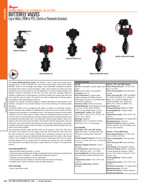
Series WE20 Butterfly Valves are offered in lug or wafer body styles and is equipped with a PTFE or EPDM liner. The most critical aspect of the Series WE20 Butterfly Valves is the cartridge seat design, which alleviates installation problems associated with common “dove tail design” seats. Valve torques are lower and more consistent as the seat dynamics are not dependent on being coupled between two disc and body allow the cartridge design to maintain a tighter disc to seat tolerance, providing a perfect low torque seal each and every time the valve is cycled. The seat to disc seal is independent of flange support and capable of full rated dead end service.Actuators are directly mounted creating a compact assembly for tight spaces. Limit switches are able to be mounted directly to the valves allowing for remote position with either an electric or pneumatic actuator. Electric actuators are available in weatherproof or explosion-proof, a variety of supply voltages and two-position or modulating control. Two-position actuators use the supply voltage to drive the valve open or closed, while the modulating actuator accepts a 4 to 20 mA input for valve positioning. Actuators feature thermal overload protection and permanently lubricated gear train. The pneumatic double acting actuator uses an air supply to drive the valve open and closed. The actuator has two supply ports, with one driving the valve open and the other driving the valve closed. Spring return pneumatic actuators use the air supply to open the valve, and internally loaded springs return the The pneumatic double acting actuator uses an air supply to drive the valve open and closed. The actuator has two supply ports with one driving the valve open and SPECIFICATIONSVALVE Service: Compatible liquids, gases, and steam.Body: 2-way, wafer or lug butterfly.Line Sizes:End Connections: Lug and wafer pattern designed for flanges that are ANSI Class 125 (B16.1) and ANSI Class 150 (B16.5) dimension.Pressure Limits: 225 psi (15.5 bar).Wetted Materials: Body Material: Ductile iron; Disc: 316 SS; Seat: EPDM or PTFE; O-ring: EPDM; Stem: 410 SS.Temperature Limits: Disc: EPDM: -50 to 250°F (-46 to 121°C); PTFE: 0 to 300°F (-18 to 149°C).Bearings: Nylatron.2 to 6˝ 10-position locking hand lever; 8 to 12˝: manual gear.Pneumatic “DA” and “SR” Series DA series is double acting and SR series is spring return (rack and Electric “TD” and “MD” SeriesPower Requirements:VAC or 24 VAC.Power Consumption: manual.Cycle Time (per 90°): 4 s; TD02 and MD02: 20 s; TD03 and MD03: 30 s; TD04 and MD04: 30 s; TD05 and MD05: 30 s; TD06 and MD06: 45 s; TD07 and MD07: 30 s.Duty Rating: Enclosure Rating: Housing Material: aluminum.Temperature Limits: to 60°C).Electrical Connection:Modulating Input: Standard Features: position indicator, and TD models come with two limit switches.Electric “TH and MH SeriesPower Requirements: WE20-CHD00-LEWE20-EDA06-LE WE20-CDA04-WP-AA07WE20-ETD04-LE-AWE20-CDA04-WP-NN08V I D E O O NL IN E415Valves,Butterfly, AutomatedVALVESBUTTERFLY VALVESLug or Wafer, EPDM or PTFE, Electric or Pneumatic ActuatorsSERIES WE20 | W.E. ANDERSON ™ BY DWYER®DWYER INSTRUMENTS, INC. | MODEL CHARTSize Cv (gal/min)Popular Hand Operated Model Price Popular Double ActingPneumatic Model Price PopularSpring Return Pneumatic Model Price NEMA 4X Two- Position Electric (110 VAC) Model Price NEMA 4XModulating Electric(110 VAC) Model Price 2˝2-1/2˝3˝4˝5˝6˝8˝10˝12˝13522030260010221579313653408250WE20-AHD00-WE WE20-BHD00-WE WE20-CHD00-WE WE20-DHD00-WE WE20-EHD00-WE WE20-FHD00-WE WE20-GHD00-WE WE20-HHD00-WE WE20-IHD00-WE $109.00b 123.00b 137.00b 183.00b 229.00b 287.00b 706.00b 972.00b 1419.00b WE20-ADA03-WE WE20-BDA03-WE WE20-CDA04-WE WE20-DDA05-WE WE20-EDA06-WE WE20-FDA07-WE WE20-GDA08-WE WE20-HDA09-WE WE20-IDA11-WE $252.00b 270.00b 309.00b 385.00b 485.00b 586.00b 1024.00b 1507.00b 2016.00bWE20-ASR04-WE WE20-BSR04-WE WE20-CSR06-WE WE20-DSR07-WE WE20-ESR08-WE WE20-FSR09-WE WE20-GSR10-WE WE20-HSR11-WE WE20-ISR11-WE$291.00b 309.00b 384.00b 474.00b 637.00b 943.00b 1465.00b 2351.00b 2447.00bWE20-ATD02-WE-A WE20-BTD02-WE-A WE20-CTD02-WE-A WE20-DTD03-WE-A WE20-ETD04-WE-A WE20-FTD04-WE-A WE20-GTD05-WE-A WE20-HTD06-WE-A WE20-ITD07-WE-A$623.00b 641.00b 660.00b 989.00b 1253.00b 1324.00b 1842.00b 2563.00b 2814.00b WE20-AMD02-WE-A WE20-BMD02-WE-A WE20-CMD02-WE-A WE20-DMD03-WE-A WE20-EMD04-WE-A WE20-FMD04-WE-A WE20-GMD05-WE-A WE20-HMD06-WE-A WE20-IMD07-WE-A$1130.00b 1152.00b 1167.00b 1593.00b 1858.00b 1930.00b 2510.00b 3260.00b 3382.00bb Items are subject to Schedule B discounts.MODEL CHART - HAND OPERATED & PNEUMATIC ACTUATOR Example WE20-BSR04-WE -A A 00WE20-BSR04-WE-AA00Price Series WE20Butterfly valve -Size and Actuator AHD00BHD00CHD00DHD00EHD00FHD00GHD00HHD00IHD00ADA03BDA03CDA04DDA05EDA06FDA07GDA08HDA09IDA11ASR04BSR04CSR06DSR07ESR08FSR09GSR10HSR11ISR112˝ hand operated 2-1/2˝ hand operated 3˝ hand operated 4˝ hand operated 5˝ hand operated 6˝ hand operated 8˝ hand operated 10˝ hand operated 12˝ hand operated 2˝ double acting 2-1/2˝ double acting 3˝ double acting 4˝ double acting 5˝ double acting 6˝ double acting 8˝ double acting 10˝ double acting 12˝ double acting 2˝ spring return 2-1/2˝ spring return 3˝ spring return 4˝ spring return 5˝ spring return 6˝ spring return 8˝ spring return 10˝ spring return 12˝ spring return $109.00b 123.00b137.00b 183.00b 229.00b 287.00b 706.00b 972.00b 1419.00b 252.00b 270.00b 309.00b 385.00b 485.00b 586.00b 1024.00b 1507.00b 2016.00b 291.00b 309.00b 384.00b 474.00b 637.00b 943.00b 1465.00b 2351.00b 2447.00bBody Type /Liner WE WP LE LP Wafer-EPDM Wafer-PTFE Lug-EPDM Lug-PTFE -+53.50b +8.60b+62.00bSolenoid N A No solenoid NEMA 4X NAMUR solenoid -+53.50b Solenoid Voltage N A B C D E No solenoid 120 VAC 220 VAC 24 VAC 24 VDC 12 VDC ------Positioner and Switches 000102030406070809None 42AD0 exp limit switch 45VD0 exp position transmitter 42AD0-B ATEX limit switch 42AD0-IE IECEX limit switch QV-210101 poly limit switch VPS and P1 prox switch 265ER-D5 positioner 285ER-D5 smart positioner -+245.00b +558.00b+343.00b +340.00b +153.00b +219.00b +679.00b +1592.00bOptions NO Fail open spring return actuator -b Items are subject to Schedule B discounts.MODEL CHART - ELECTRIC ACTUATORExample WE20-DMH05-WE -A WE20-DMH05-WE-A Price Series WE20Butterfly valve -Size and Actuator ATD02BTD02CTD02DTD03ETD04FTD04GTD05HTD06ITD07AMD02BMD02CMD02DMD03EMD04FMD04GMD05HMD06IMD07ATH03BTH03CTH05DTH05ETH06FTH08GTH09HTH10ITH11AMH03BMH03CMH05DMH05EMH06FMH08GMH09HMH10IMH112˝ NEMA 4X two-position 2-1/2˝ NEMA 4X two-position3˝ NEMA 4X two-position 4˝ NEMA 4X two-position 5˝ NEMA 4X two-position 6˝ NEMA 4X two-position 8˝ NEMA 4X two-position 10˝ NEMA 4X two-position 12˝ NEMA 4X two-position 2˝ NEMA 4X modulating 2-1/2˝ NEMA 4X modulating 3˝ NEMA 4X modulating 4˝ NEMA 4X modulating 5˝ NEMA 4X modulating 6˝ NEMA 4X modulating 8˝ NEMA 4X modulating 10˝ NEMA 4X modulating 12˝ NEMA 4X modulating 2˝ exp two-position 2-1/2˝ exp two-position 3˝ exp two-position 4˝ exp two-position 5˝ exp two-position 6˝ exp two-position 8˝ exp two-position 10˝ exp two-position 12˝ exp two-position 2˝ exp electric modulating 2-1/2˝ exp electric modulating 3˝ exp electric modulating 4˝ exp electric modulating 5˝ exp electric modulating 6˝ exp electric modulating 8˝ exp electric modulating 10˝ exp electric modulating 12˝ exp electric modulating$623.00b 641.00b 660.00b 989.00b 1253.00b 1324.00b 1842.00b 2563.00b 2814.00b 1130.00b 1152.00b 1167.00b 1593.00b 1858.00b 1930.00b 2510.00b 3260.00b 3382.00b 623.00b 641.00b 2635.00b 2696.00b 3031.00b 3328.00b 3843.00b 5914.00b 6575.00b 1130.00b 1152.00b 3912.00b 3974.00b 4308.00b 4330.00b 4865.00b 7025.00b 7901.00bMaterial/Liner WE WP LE LP Wafer-EPDM Wafer-PTFELug-EPDM Lug-PTFE-+53.50b +8.60b +62.00bActuator Voltage A B C D 110 VAC 220 VAC24 VAC 24 VDC--+75.00b +75.00bb Items are subject to Schedule B discounts.ACCESSORIES Model Description Price AFR4VB-01Air filter regulator 0 to 120 psi Volume booster $72.00b 182.00b b Items are subject to Schedule B discounts.。
沃纳道 V-Flow 通风器用户指南说明书
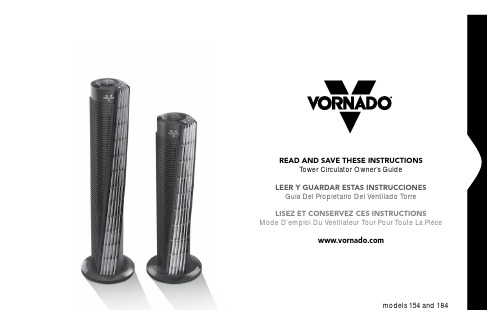
READ AND SAVE THESE INSTRUCTIONSTower Circulator Owner’s GuideLEER Y GUARDAR ESTAS INSTRUCCIONES Guía Del Propietario Del Ventilado Torre LISEZ ET CONSERVEZ CES INSTRUCTIONS Mode D’emploi Du Ventilateur Tour Pour Toute La PiéceDesigned, engineered and supported in Andover, Kansas.Pensado, diseñado y respaldado en Andover, Kansas. Conception, mise au point et soutien technique effectués à Andover, au KansaQuestions or comments?¿Prequntas o comentarios?Questions ou commentaires?***************************800.234.0604Español p. 13Français p. 23Important Instructions (4)Vornado V-Flow™ Circulation (6)Features and Benefits (7)Base Assembly Instructions (7)How To Use (8)Controls (9)Operating Tips (10)Cleaning and Storage (10)Troubleshooting (11)Warranty (12)Contentsthe glass center portion. Close the fuse access cover (D.) by sliding the cover back into the plug until it is completely closed, latches and is flush with the face of the plug. Risk of fire. Do not replace attachment plug. Contains a safety device (fuse, AFCI, LCDI) that should not be removed. Discard product if the attachment plug is damaged.This unit requires one (1) lithium coin cell battery (CR2032), 3 Volt(included). DO NOT DISPOSE OF BATTERIES IN FIRE. BATTERIES MAY EXPLODE OR LEAK.WARNING: Keep away from children. If swallowed call (800) 222-1222 or (202)625-3333, in Canada (416) 813-5900.NOTE: This equipment has been tested and found to comply with the limits for Class B digital device, pursuant to part 15 of the FCC Rules. These limits are designed to provide reasonable protectionagainst harmful interference in a residential installation. This equipment generates, uses and can radiate radio frequency energy and, if notinstalled and used in accordance with the instructions, may cause harmful interference to radio or television reception, which can be determined by turning the equipment off and on, the user is encouraged to try to correct the interference by one or more of the following measures:This appliance has a polarized plug. (One blade is wider than the other.) To reduce the risk of electrical shock, this plug is intended to fit in a polarized outlet only one way. If the plug does not fit fully in the outlet, reverse the plug. If it still does not fit, contact a qualified electrician. Do not attempt to defeat this safety feature.WARNING – To reduce the risk of fire or electrical shock, do not use this product with any solid state speed control device. To reduce the risk of fire or electric shock and injury to persons, do not use in a window. This product employs overload protection (fuse). A blown fuse indicates an overload or short-circuit situation. If the fuse blows, unplug the product from the outlet. Replace the fuse as per the user servicing instructions (follow product marking for proper fuse rating) and check the product. If the replacement fuse blows, a short-circuit may be present and the product should be discarded or returned to an authorized service facility for examination and/or repair.Do unplug your Tower Circulator before cleaning.Do clean your Vornado Tower Circulator regularly. Refer to theCLEANING instructions provided. Never clean the air circulator in any manner other than as instructed in this manual.Do Not use gasoline, thinners, solvents, ammonia or other chemicals for cleaning.Do Not immerse this product in water or allow water to drip into the motor housing.Do Not use near furnaces, fireplaces, stoves or other high-temperature heat sources.Do Not position this product too close to draperies because they may be drawn into the rear grill, cutting off airflow. Do Not use this product outdoors.Do Not use this product on wet surfaces.Do Not use this product in a bathtub or shower.Do Not use this product if it has a damaged cord or plug. Discard fan or return to an authorized service facility for examination and/or repair. Do Not carry this product by the cord, or use the cord as a handle. Do Not attempt to repair or replace parts.Do Not run cord under carpeting. Do Not cover cord with throw rugs, runners, or similar coverings. Do not route cord under furniture orappliances. Arrange cord away from traffic area and where it will not be tripped over.Do Not operate the Tower Circulator on an elevated surface, such as a shelf or desktop, use only while placed on the floor.Do use common sense when using this product and/or any electrical appliance.User Servicing InstructionsGrasp plug and remove from the receptacle or other outlet device. Do not unplug by pulling on cord. Open fuse cover (A.) by sliding access cover on top of attachment plug towards blades. Remove fuse (B.) carefully by gently prying out the ends of the fuse from the receptacle.Risk of fire. Replace fuse only with 2.5 Amp, 125 Volt fuse. ContactVornado customer service for replacement fuse. Phone: 1-800-234-0604, email:***************************Install replacement fuse (C.) by first placing the end of the fuse into the fuse receptacle which is opposite of the blades of the plug, then carefully push in the other end. Only push against the metal end of the fuse, notIMPORTANT INSTRUCTIONSREAD ALL INSTRUCTIONS BEFORE USING THIS TOWER.SAVE THESE INSTRUCTIONSA. B. C. D.IMPORTANT INSTRUCTIONSREAD ALL INSTRUCTIONS BEFORE USING THIS TOWER.Reorient or relocate the receiving antenna.Increase the separation between the equipment and the receiver.Connect the equipment into an outlet on a circuit different from that to which the receiver is connected.Consult the dealer or an experienced radio/TV technician for help.This device complies with part 15 of the FCC Rules. Operation is subject to the following two conditions: (1) This device may not cause harmful interference, and (2) his device must accept any interference received, including interference that may cause undesired operation.This Class B digital apparatus complies with Canadian ICES-003. Cet appareil numérique de la classe B est conforme à la norme NMB-003 du Canada.Typical Tower FanTypical tower fans oscillate due to limited range of air movement. You feel the airflow for onlyseconds at a time.Trust.It is said that trust isn’t given, but earned. For decades Vornado has been earning the trust of our customers by offering them only the best. Vornado provides the highest level of performance, coupled with the highest level of support available. Complete satisfaction with no exceptions – this is Vornado’s promise to you. If you are not satisfied for any reason, please contact us. Knowledgeablerepresentatives are available at 1-800-234-0604 from 7:00 AM to 6:00 PM CST. A wealth of additional support is also available online at . On behalf of myself and the entire staff at our Andover, Kansas headquarters – thank you for selecting Vornado.Sincerely,Randy Brillhart CEO, Vornado AirFind our complete product line at N O OSC I LL A T I O N NEE DE DWith V-Flow™ Circulation V-Flow™ Circulation is a wide span of constant airflow that allows a Vornado to provide truewhole room circulation.Benefitany circulation need will be met.illuminated.of common tower fans.summertime thermostat as low.Features and BenefitsBase Assembly InstructionsPositioning Your Circulator1. Position your Tower Circulator so the airstream has an unobstructed path from one side of the room to the other, or position the airstream to blow directly at you for direct cooling.2. Set to a medium speed and allow a few minutes for an airflow pattern to be established. (Different airflow patterns can be established by changing the location, and speed of the Tower Circulator.)3. Adjust the speed accordingly until a desired comfort level is achieved. You will quickly determine the precise amount ofcirculation required to maintain your personal comfort in a given room for the prevailing temperature and humidity conditions. Once you discover the added comfort of air circulation, you will use your Vornado Tower Circulator season after season.How To UsePower (A) The unit functions ON and OFF by pressing the POWER button. Lights on the unit’s control panel indicate the power is ON.Fan Speed (B) The fan speed can be adjusted by pressing the SPEED button. Press the button to switch between the unit’s speed settings. The turbo (highest) setting is for maximum air circulation. Lights on the unit’s control panel indicate the selected speed setting.Timer (C) The unit has an automatic timer to turn the unit OFF at intervals of 1, 2, 4 or 8 hours. To set the timer, turn the unit on and select desired speed. Press the timer button until the desired run time light is illuminated. The unit will continue to run until that amount of time has expired.Remote Control This unit comes with a remote control. The remote control functions are the same as the control panel on the unit. The remote requires a line-of-sight path to allow for the signal to be received by the unit. Position the unit so the receiver lens (located above the Vornado logo) is visible from the remote control. The remote control can be stored with the Tower Circulator using the magnetic bowl-shaped cradle located on the top of the product.Remote Control Battery The remote control comes with a 3 Volt lithium coin cell battery (CR2032). To install, remove the battery cover on the bottom of the remote control. Remove any plastic protection from the battery and place it in the remote with the + side facing out. Then reposition the cover onto the bottom of the remote. If your remote does not work, please try replacing with a new 3 Volt CR2032 battery.How to CleanYour Tower Circulator has no userserviceable parts. Do not disassemble the unit. This will void your warranty. If service is required, return your circulator to Vornado (see WARRANTY for instructions on page 12).The motor is permanently lubricated and requires no oiling.Because your Tower Circulator moves a substantial amount of air, it will need regular cleaning. To clean follow these simple instructions:1. Unplug the unit.Note: Do not use gasoline, thinners, solvents or other chemicals for cleaning .2. Use the brush attachment on your household vacuum cleaner to vacuum any accumulated dust off the Front Angled Outlet Grill and Side Inlet Grill. Wipe down the entire surface with a soft cloth.the unit from accumulating dust overtime.4. Store unit in a cool and dry location.Getting the Most From Your CirculatorThank you for your purchase. It’s important for you to know that this product functions very differently than typical tower fans you may have used in the past. Here are a few things to keep in mind:Expect Powerful CirculationYour Tower Circulator is designed to move considerably more air than a traditional tower fan. Consider the following as you adjust product settings.Operating TipsUltra-high volume airflow. Increased sound lev-els may be perceptible due to airflow volume and velocity.High volume airflow. Rapidly moves air across the room for efficient cooling. Increased sound levels may be perceptible due to airflow volume and velocity.Superior circulation power compared to tradi-tional tower fans on their high setting. May be preferred for day-to-day use.Near-silent operation while offering steady cir-culation.Turbo SettingHigh SettingMiddle Setting(s)Low SettingCleaning and StorageTroubleshootingTower Circulator • 5 Year Limited WarrantyVornado Air LLC (“Vornado”) warrants to the original consumer or purchaser this Vornado® Tower Circulator (“Product”) is free from defects in material or workmanshipfor a period of five (5) years from the date of purchase, depending on model. If any such defect is discovered within the warranty period, Vornado, at its discretion, will repair or replace the Product at no cost. Repairs not covered by the warranty or outside the warranty period will require a fee to cover the cost of materials, labor, handling and shipping.This warranty does not apply to defects resulting from abuse of the Product, modification, alteration, repair or service of the Product by anyone other than Vornado, mishandling, improper maintenance, commercial use of the Product, damages which occur in shipment or are attributed to acts of God.REPAIR OR REPLACEMENT AS PROVIDED UNDER THIS WARRANTY IS THE EXCLUSIVE REMEDY OF THE CONSUMER. VORNADO SHALL NOT BE LIABLE FOR ANY INCIDEN-TAL OR CONSEQUENTIAL DAMAGES FOR BREACH OF ANY EXPRESS OR IMPLIED WARRANTY ON THIS PRODUCT. EXCEPT TO THE EXTENT PROHIBITED BY APPLICABLE LAW, ANY IMPLIED WARRANTY OF MERCHANTABILITY OR FITNESS FOR A PARTICULAR PURPOSE ON THIS PRODUCT IS LIMITED IN DURATION TO THE DURATION OF THIS WARRANTY.Some states do not allow the exclusion or limitation of incidental or consequential dam-ages, or allow limitations on how long an implied warranty lasts, so the above limitations or exclusions may not apply to you. This warranty gives you specific legal rights, and you may have other rights that vary from state to state.For warranty or repair service, call 1-800-234-0604 or email *******************************************************(“RA”)form.Pleasehaveor include your Product’s model number and serial number, as well as your name, address,city, state, zip code and phone number when contacting Vornado for warranty service.After receiving the RA form, ship your Product to:Vornado Air LLCAttn: Warranty & Repair415 East 13th StreetAndover, KS 67002For your convenience, please have your model number and serial number when contact-ing Vornado with service inquiries. To assure proper handling, packages must be clearlymarked with the RA number. Packages not clearly marked with the RA number may berefused at the receiving dock.Please allow 1-2 weeks for repair and return of your Product after the Product is received.For your records: Staple or attach your original sales receipt to this Owner’s Guide. Pleasealso write your products’s serial number below (located on product specs decal).Serial No. ______________________________________Product registration available online at © 2014 Vornado Air LLC Andover, KS 67002Patents Pending. Specifications subject to change without notice.Vornado® is a trademark owned by Vornado Air LLC.Designed, engineered and supported in Andover, KS.Manufactured in China.*********************************************.234.0604Instrucciones Importantes (14)Circulacion V-Flow™ Vornado (16)Características y Beneficios (17)Instrucciones De Montaje Base (17)Cómo Usar (18)Controles (19)Consejos De Operación (20)Limpieza Y Almacenamiento (20)Resolución De Problemas (21)Garantía (22)ContenidoCL3-0354 R-Speak your mind /reviews Hable con franqueza /reviews Exprimez-vous! /reviewsVornado Air, LLC415 East 13th Street, Andover, Kansas 67002800.234.0604 │ 。
空气式脉动阻尼器安全操作及保养规程

空气式脉动阻尼器安全操作及保养规程前言空气式脉动阻尼器是一种常见的机械元件,广泛应用于工业设备、船舶、轨道交通等领域。
本文旨在介绍空气式脉动阻尼器的安全操作及保养规程,以确保使用过程中的安全性和可靠性。
空气式脉动阻尼器的基本原理空气式脉动阻尼器是一种通过空气阻力来实现阻尼的机械元件。
其主要部件为活塞、缸体和空气阀。
当活塞移动时,空气阀会自动打开或关闭,从而改变气体的流量和阻力大小,实现阻尼效果。
安全操作规程1. 使用前检查在使用空气式脉动阻尼器之前,应当对其进行检查,确保各部件的正常工作。
具体检查内容包括:•活塞的行程是否正常,是否有卡滞现象;•缸体的表面是否有裂纹或损伤;•空气阀是否通畅,是否有泄漏;•其他附件是否齐全、完好。
2. 安装应注意的事项安装空气式脉动阻尼器时,应注意以下事项:•所有连接均应紧固、可靠,避免松动或漏气;•安装位置应固定,不应有过大的振动或冲击;•接口处应涂抹油脂,以便拆卸时易于操作。
3. 操作过程中的注意事项在操作空气式脉动阻尼器时,应注意以下事项:•不得超过额定工作压力;•不得超过额定工作温度;•避免产生过大的振动或冲击;•不得将空气式脉动阻尼器用于不符合其规定范围的场合。
4. 停用时的处理停用空气式脉动阻尼器时,应按以下方式处理:•释放内部气压;•清洁表面污垢;•若长时间停用,应涂抹适量润滑油,并做好防潮、防锈措施。
保养规程为了保证空气式脉动阻尼器的正常运行,应按以下规程进行保养:1. 定期检查定期检查空气式脉动阻尼器的各部件,确保它们的正常工作。
具体检查内容包括:•活塞行程是否正常,是否有卡滞现象;•缸体表面是否有裂纹或损伤;•空气阀是否通畅,是否有泄漏;•润滑油是否充足。
2. 清理保养清理空气式脉动阻尼器的外部污垢,保持其表面干净。
需要注意:•不得使用含有腐蚀性物质的溶剂;•不得使用高压水枪清洗;•不得使用金属刷子或其他硬物擦拭。
3. 更换配件需要更换的配件包括气缸密封件、气阀等。
沃纳阻尼器安全操作及保养规程

沃纳阻尼器安全操作及保养规程沃纳阻尼器是一种常用的工业机械部件,常见于各种机器设备和运输工具中。
它能够起到减震、降噪和减少震动的作用,防止机器设备在工作时产生较大的波动和震动。
虽然沃纳阻尼器作为一种常见的零件,但如果在使用时不注意安全操作和保养,就会对设备和人员造成不可估量的损害。
因此,对沃纳阻尼器的安全操作及保养规程需要特别重视。
本文将详细介绍沃纳阻尼器的安全操作和保养规程,以便更好地使用沃纳阻尼器和保证设备和工作人员的安全。
沃纳阻尼器的安全操作规程1. 熟悉沃纳阻尼器的使用范围和性能在实际应用过程中,要首先熟悉沃纳阻尼器的使用范围和性能,以免在使用时超出其承受范围而导致设备损坏或人员伤亡。
同时,在购买沃纳阻尼器时,应选择适合实际使用环境和设备的型号和规格,不要随意更换或混用。
2. 正确认知沃纳阻尼器的安装方式沃纳阻尼器的安装方式很重要,正确的安装方式不仅可以提高工作效率,还能保证设备和人员的安全。
在安装时,需要遵循安装说明,正确选择安装位置和固定方式。
安装时应保证沃纳阻尼器与设备之间的间隔和支撑点的结构设计符合安装说明,并使用符合国家标准的螺栓、垫圈等连接件进行固定。
3. 在使用前进行检查和试运行为了确保沃纳阻尼器的正常运行和设备的安全,使用前需要进行检查和试运行。
检查沃纳阻尼器的固定、密封、润滑、弹簧是否完好,是否有异常磨损和松动等情况。
试运行时,应先开启设备,让沃纳阻尼器在低速状态下运转,检查有无异常震动和杂音,确保设备正常运转后才能进入正式工作。
4. 在使用时注意避免过载和超速运转沃纳阻尼器有其使用范围和承受负荷的极限,不同型号和规格的沃纳阻尼器承受能力也有所不同。
因此,在使用时不能超载或超速运行。
如果超出沃纳阻尼器的承受范围,就会导致阻尼器失效或损坏,进一步危及设备和人员的安全。
5. 在使用过程中及时检查和保养沃纳阻尼器沃纳阻尼器在使用过程中,可能会出现固定松动、密封不良、润滑不足等问题。
德国原装沃纳wonner阻尼器DBS150-EWDW
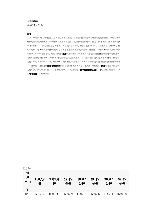
三角洲BS15高达15公斤应用停止一个或多个积累的托盘支架在规定的停止区域。
应用适用于输送冲击敏感或脆弱的部位。
利用自动装配和处理系统分离停止。
气动激活与无级可调阻尼。
坚固和经济分离站,阻尼。
的冲击力,因此由高达9 5%相比降低了,而无需阻尼分离停止。
可以使用以6米/分的输送速度36米/分。
权重可以从约250 g且高可衰减。
的DBS15分离停止使用电子传感器来检测止动板的上和下的位置。
分离站DBS15可以安装到博世力士乐TS1输送系统,无需转接板。
设计铝基本住房与硬阳极氧化涂层止动板材质为黄铜气动分离站,无级可调阻尼最优0.25公斤和15之间的阻尼在托盘架重量公斤托盘支架负载高达15公斤允许(传送带速度6米/分)的单作用分离停止DBS15可以转向双重作用,使得在启动所述挡板的被加速和分离站准备下一次分离。
过程更快范围/供应条件的所有零配件都提供安装,根据客户的要求。
微调阻尼力和阻尼的速度可以在设备顶部设置:+ =增加阻尼力- =降低阻尼力,技术数据操作压力[bar]处理的压缩空气4 - 8条气动连接 M5螺纹气源阻尼力:速度vѹ)6米/分钟9米/分钟12米/分钟18米/分钟24米/分钟30米/分钟36米/分钟块0,25-15公斤0,25-10公斤0,25-9公斤0,25-7公斤0,25-6公斤0,25-4公斤0,25-2公斤¹)此信息适用于0.07μ(三角洲EL20 0,1μ)托盘架和传送带之间的摩擦为标准沃纳停止。
所有重量资料中涉及的托盘保持件(托板带材料)的总重量,不向轴向力。
其他脉动阻尼器安全操作及保养规程
其他脉动阻尼器安全操作及保养规程脉动阻尼器是一种常用于工业机械传动系统中的零部件,以其简单、可靠、高效的特点得到广泛应用。
在正常运转过程中,我们需要注意脉动阻尼器的使用和保养,以确保其安全可靠地工作。
本文将介绍其他脉动阻尼器的安全操作和保养规程。
1. 使用前须知在使用其他脉动阻尼器前,需要进行以下几项确认:1.确认脉动阻尼器型号和规格是否与传动系统匹配;2.确认脉动阻尼器是否安装正确,螺栓是否固定;3.确认脉动阻尼器与传动系统的其他零部件是否依照规定安装,运行时是否存在摩擦、卡顿、振动等异常情况。
2. 安全操作规程2.1 启动和运行启动和运行其他脉动阻尼器时,需要注意以下几点安全操作规程:1.在开动机器前,按照相关操作规程检查脉动阻尼器的各项性能指标,确保其工作正常;2.启动机器后,逐步升高速度和负荷,防止脉动阻尼器因突然负荷而烧毁;3.在停机前,将脉动阻尼器恢复到低速状态,避免其过快停止,造成损伤。
2.2 检修和更换在进行脉动阻尼器的检修和更换时,需要注意以下安全操作规程:1.首先必须切断所有的电源或机械动力,防止危险的发生;2.在检修和更换过程中,必须按照相关操作规程及时记录脉动阻尼器的型号、规格、生产日期等信息,以便于后续的检查和维护;3.在更换时,需要选择同样品牌和型号的脉动阻尼器,严格按照相关规程更换,确保更换后的脉动阻尼器符合要求。
3. 保养规程定期保养脉动阻尼器对提高其使用寿命及工作效率是非常重要的。
在执行保养规程时,需要注意以下几点:1.每次使用结束后,应该定期对脉动阻尼器进行表面和内部的清洗及检查,清除杂物、污物等;2.定期进行润滑、检查螺栓是否松动;3.定期检查脉动阻尼器内部的元件是否磨损、损坏等,及时更换;4.按照严格的保养计划保养脉动阻尼器,增加其使用寿命及工作效率。
4. 安全注意事项在操作脉动阻尼器时,需要注意以下几点安全注意事项:1.不要过度负载脉动阻尼器,以免损坏;2.定期检查脉动阻尼器的性能指标,确保其正常工作;3.不要擅自更换型号、规格不符的脉动阻尼器,以免造成传动系统出现问题;4.在检修、更换时,必须切断所有的电源或机械动力。
脉动阻尼器说明书

一.原理脉动阻尼器的工作原理是遵循波义尔定律:即在恒定温度下一定量的气体的绝对压力与体积成反比。
脉动阻尼器内装有弹性隔膜。
隔膜将上部内腔中的压缩气体和下部外腔中的被输送流体隔开。
当计量泵进入排出行程,液体被压入管路,使得管路压力不断升高,当此压力超过脉动阻尼器的预充压力,隔膜被物料顶着向上运动,部分液体将会进入阻尼器。
直到隔膜两侧压力平衡。
当泵排出行程结束,管路压力下降,阻尼器内气体腔中的压力大于管路的压力,于是,隔膜被气体压回其原始的位置,并将物料压回管路中。
在泵的每个循环冲程中,计量泵与脉动阻尼器产生两个脉冲波,并进行叠加。
脉动阻尼器起到了“消峰填谷”作用,从而有效地缓和了被输送流体的脉动。
二.安装:在安装、操作、维护脉动阻尼器时,应采取合适的安全措施。
操作设备时,应使用适宜的工具、防护服和护目镜。
存在危险介质(如腐蚀物,有毒物,溶剂、酸、碱、可燃物等)时应采取合适的附加安全措施。
为了使脉动阻尼器最有效,应尽可能靠近泵出口。
靠近阻尼器设置一个截止阀可方便维修或更换隔膜,并缩短停机时间。
当管路压小于1.5bar时,需在脉动阻尼器下游安装背压阀,通过背压阀的调节,保持管路压力稳定。
在脉动阻尼器下游与背压阀之间,应加装隔膜压力表。
以便及时观察管路压力情况。
在装有脉动阻尼器的管路系统中,必须要装有安全阀。
三.充气在确定管路压力情况下,通过脉动阻尼器的充气阀,向阻尼器内充入氮气,气压控制在管路压力的70%左右。
(在工艺条件允许情况下,也可充入压缩空气) 四.维护脉动阻尼器在日常工作中,只需直观观察其是否正常工作,无需过量维护。
当然定期检查隔膜,有助于系统的稳定。
在检查或更换隔膜时,应先排尽阻尼器内的气体,并需采取适当的安全措施,以防输送液体飞溅伤人。
五.常见故障及措施脉动阻尼器不起作用---------脉动阻尼器没有充气或充气不足,重新充气。
脉动阻尼器充气过多,通过充气阀适当放气。
脉动阻尼器隔膜破损(漏气),更换隔膜。
威纳尔(Werner)公司产品安装说明书:钢铁和铝制侧箱与包裹箱(Pack Rat)抽屉单元

NOTICEWARNINGDANGERCAUTIONUse specific aluminum upfit components when installing WEATHER GUARD® products to aluminum truck beds. Follow additional instructions if mounting to an aluminum truck bed. There may be left over components depending on upfit.Any modification or unintended use of this product shall immediately void all manufacturers warranties. Manufacturer disclaims all liability for injuries to persons or property resulting from any modification to, or unintended use of this product.Danger of explosion. Do not use this product for storing or transporting flammables, explosives, hazardous materials, or hazardous waste, such as containers of gasoline, solvents, gun powder, dynamite, propane tanks, acetylene tanks and cutting torches. This product is only intended and safe for use in storing and transporting small tools, equipment and other similar materials. Any modifications made to, or unintended use of this product, could create a hazardous condition that can cause death, serious personal injury or property damage.Prior to drilling, so as not to cut or puncture fuel tanks, fuel lines, electric wires, etc., check under vehicle for locations. All floor mounting bolts near the gas tank area should be installed from the underside of the vehicle, to guard against the gas tank being punctured in the event of a collision. This would mean not using Blind Fastener in this area. Holes drilled in this area should be 3/8".To keep debris out of your eyes when checking the underside of the vehicle, or when drilling, always wear protective eyewear.Some of the larger drawers would best be handled by two people, so as not to cause injury to your person.(1) HandleALUMINUM BED UPFIT KIT PARTS LIST - 32-0244(4) Vinyl Tape(1)Zinc Rich Primer(28) 1/2" x 1"Plastic Washer(1) Rear Mounting BracketBLIND FASTENER INSTALLATIONPlace a drop of oil on black oxide bolt for lubrication before assembling.STEP 1STEP 2STEP 2ADrawer RemovalOpen the drawer until it reaches the internal stop brackets. Remove the stop brackets from each upper inside location. Put the brackets and bolts into the drawer for later installation. Install the drawer handle. Carefully pull the drawer completely out of the housing, setting it aside. Lift out the front rollers.Drawer Installation (preferred)Place the housing in position. Slide a mounting plate into each open end of the front and rear skids, but no farther than the leading edge of the slotted hole in the mounting plate. Mark through the hole for drilling. See Blind Fastener Installation Instructions and cautions before drilling. With Blind Fasteners installed, secure by placing the mounting plate as you had for marking.Note: Follow figure to the right as a guide.Drawer Installation (alternate)Place the housing into the position, and mark through the outer slotted holes of each skid. Remove the housing and read the Blind Fastener Installation Instructions and cautions before drilling each of the hole locations. With all Blind Fasteners installed, secure the housing. Reinstall thedrawer to the unit by reversing the removal steps shown.5/16-18 x 1-1/2"Hex Head Bolt5/16-18 x 1-1/2"Hex Head Bolt5/16" Lock Washer5/16" Lock Washer5/16" Flat Washer5/16" Flat Washer MOUNTING PLATE1/2" Hole1/2" Hole5/16-18 Blind Fastener5/16-18 Blind FastenerSTOP BRACKETS DRAWERHANDLE5/16-18 x 3/4" Truss Head Screw5/16-18 Whiz Lock NutFRONT ROLLERSHOUSING5/16-18 x 3/4" Hex Head BoltINSTALLATION INSTRUCTIONSNote: If your truck bed is constructed of aluminum, use zinc rich primer to coat drilled holes.STEP 3Stacking PACK RAT® Drawer UnitsRear Mount Bracket Installation (alternate)If space is critical and/or for some reason you cannot mount the rear in either the preferred method or use the mounting plates at the rear, you may use the rear mounting bracket. Locate the center line of the housing and place the bracket flush against the back and flush to the floor. If necessary, you may turn the bracket so the floor flange is under the rear overhang of the housing. Hole marking will be more difficult. Mark only the two floor holes for drilling. See Blind Fastener Installation Instructions and cautions before drilling. With Blind Fasteners installed, fasten the bracket to the floor. Mark and drill holes on the back of the housing for Blind Fastener installation. With Blind Fasteners installed, replace the housing and secure to the bracket.1/2" Hole1/2" Hole5/16-18 x 1-1/2"Hex Head Bolt5/16-18 x 1"Hex Head Bolt5/16" Lock Washer5/16" Lock Washer 5/16" Flat Washer5/16" Flat Washer5/16-18 Blind Fastener5/16-18 Blind Fastener1/2" Hole1/2" Hole5/16-18 x 1-1/2"Hex Head Bolt5/16-18 x 1"Hex Head Bolt5/16" Lock Washer CENTER LINE OF HOUSING5/16" Lock Washer5/16"Flat Washer5/16" Flat Washer5/16-18 Blind Fastener REAR MOUNTING BRACKETREAR MOUNTING BRACKETINSET• Do not install bolts in the rear of the upper housing at this time.• See Inset below for installation details. Do not use outer-most obround holes, fasteners would obstruct lower unit drawer travel. When stacking PACK RAT® units in an open vehicle, apply sealant (local purchase) to drilled holes in the drawer unit bodies.With the lower PACK RAT® unit properly bolted in place, mount the rear mounting bracket to the top rear edge of the unit as shown. The bracket will be mounted to the bottom first. Put the upper PACK RAT® unit in position on top of the lower and mark the back mounting holes for blind fastener installation. With the upper housing in proper bolting position (with drawer and rollers removed), mark through inner two obround holes in the front mounting skid for Blind Fastener installation. With front Blind Fasteners installed, fasten the upper housing to the lower.Note: STEP 2B。
系列在线脉动阻尼器安全操作及保养规程
系列在线脉动阻尼器安全操作及保养规程1. 前言本文档旨在为使用系列在线脉动阻尼器的操作人员提供详细的安全操作和保养规程。
在线脉动阻尼器在工业生产中起着重要的作用,但如果不正确操作或保养,可能会导致设备故障或人员伤害。
因此,了解并遵守本规程是非常重要的。
2. 设备简介•系列在线脉动阻尼器是一种用于减轻管道系统内液体脉动的装置。
•它通过嵌入式阻尼器减少压力变动,并提供更平稳的流体流动。
•该装置适用于各种工业领域,如化工、石油、食品加工等。
3. 安全操作规程3.1 使用前的检查在使用系列在线脉动阻尼器之前,必须进行以下检查:•确保阻尼器与管道系统连接紧密,无泄漏。
•检查阀门和管道系统的安全阀是否正常工作。
•确保阻尼器的压力等级和工作温度适用于所需应用。
3.2 正确操作步骤正确操作系列在线脉动阻尼器需要遵循以下步骤:1.开始操作前,确保操作人员已经接受了相关培训并具备操作技能。
2.打开进气阀门,允许流体进入阻尼器。
3.监控仪表上的压力变化,并确保设备在正常工作范围内。
4.如果压力超过设定范围,立即关闭进气阀门,并检查设备是否存在故障。
5.在停止使用阻尼器之前,先关闭进气阀门,并等待压力释放完全。
6.定期检查阻尼器的工作状态和性能。
3.3 注意事项在使用系列在线脉动阻尼器时,请注意以下事项:•阻尼器操作过程中,严禁将手或其他物体伸入设备内部。
•在阻尼器工作期间,禁止将过大的压力施加在阻尼器上。
•如果发现任何异常情况或故障,请立即停止使用,并寻求专业人员的帮助。
•在进行保养和检修时,请先关闭进气阀门,并确保压力已完全释放。
4. 保养规程4.1 定期检查为确保系列在线脉动阻尼器的正常运行,需要定期进行以下检查:•检查阻尼器的密封性能,确保没有泄漏。
•清洁阻尼器的内部和外部表面,以去除灰尘、污垢等。
•检查阻尼器的仪表和控制系统是否正常工作。
•检查阻尼器的管道连接是否紧固,无松动现象。
4.2 保养步骤系列在线脉动阻尼器的保养步骤如下:1.首先,关闭进气阀门,并确保压力已完全释放。
旺纳电动机械沿用手册说明书

For other service manuals visit our website at:/manuals-literature851-968 Rev. ARecord Conveyor Serial Number HereAquaGard ® LPGearmotor Mounting PackagesInstallation, Maintenance & Parts ManualSide 90°Bottom 90°Bottom Parallel ShaftDorner Mfg. Corp.2851-968 Rev. AAquaGard® LP Gearmotor Mounting PackagesWarnings - General SafetyA WARNINGThe safety alert symbol, black triangle with white exclamation, is used to alert you to potential personal injury hazards.Climbing, sitting, walking or riding on conveyor will cause severe injury.KEEP OFF CONVEYORS.DO NOT OPERATE CONVEYORS IN AN EXPLOSIVE ENVIRONMENT.A WARNINGSEVERE HAZARD!LOCK OUT POWER before removing guards or performing maintenance. Exposed moving parts can cause serious injury.A WARNINGGearmotors may be HOT.DO NOT TOUCH Gearmotors.A WARNINGExposed moving parts can cause severe injury.REPLACE ALL GUARDS BEFORE RUNNING CONVEYOR.A WARNINGDorner cannot control the physicalinstallation and application of conveyors. Taking protective measures is the responsibility of the user.When conveyors are used in conjunction with other equipment or as part of a multiple conveyor system, CHECK FOR POTENTIAL PINCH POINTS and other mechanical hazards before system start-up.851-968 Rev. A3Dorner Mfg. Corp.AquaGard® LP Gearmotor Mounting PackagesProduct DescriptionRefer to (Figure 1) for typical gearmotor assembly components.Figure 1SpecificationsGearmotor Mounting PackageFastener Torque SpecificationsDorner recommends FDA approved grease on all threaded stainless steel fasteners.1Mounting Plate 2Gearmotor 3Motor Control213Hex HeadSet ScrewHex Size Torque Hex Size Torque M3 x 0.5 5.5 mm 0.9 Nm (8 in lbs) 2 mm 0.2 Nm (1.7 in lbs)M4 x 0.77 mm 2.3 Nm (20 in lbs) 2 mm 0.7 Nm (6 in lbs)M5 x 0.88 mm 4.6 Nm (40 in lbs) 2.5 mm 1.5 Nm (13 in lbs)M6 x 1.010 mm 7.8 Nm (69 in lbs) 3 mm 2.5 Nm (22 in lbs)M8 x 1.2513 mm 19.0 Nm (169 in lbs) 4 mm 6.0 Nm (53 in lbs)M10 x 1.516 mm38.0 Nm (335 in lbs)5 mm12.0 Nm (106 in lbs)Dorner Mfg. Corp.4851-968 Rev. AAquaGard® LP Gearmotor Mounting PackagesInstallationDrive Package TypesIdentify your drive package type:•Side Drive Package•Bottom 90° Drive Package•Bottom Parallel Shaft Drive PackageSide Drive PackageFigure 2Typical Side Drive Package Components (Figure 3).Figure 3Bottom 90° Drive PackageFigure 51Side Mounting 2Coupling 3Gearmotor 4Screw (2x)5GuardNOTEGearmotor may be operated in positions 1 through 4 (Figure 4).851-968 Rev. A5Dorner Mfg. Corp.AquaGard® LP Gearmotor Mounting PackagesFigure 6Figure 7Figure 8Typical Bottom Parallel Shaft Drive Package Components(Figure 9).Figure 9NOTEGearmotor may be operated in positions 1 through 3 (Figure 7).861Cover 2Screw (2x)3Mounting PlateDorner Mfg. Corp.6851-968 Rev. AAquaGard® LP Gearmotor Mounting PackagesInstallationDrive Package Installation•Side Mount •Bottom 90° Mount•Bottom Parallel Shaft MountRequired Tools• 2.5 mm hex wrench •7 mm wrench •8 mm wrench •10 mm wrench •13 mm wrench •Straight edge •Torque wrenchInstall Side Mount Drive Package1.Install mounting bracket (Figure 10,item 1) onto drive end of conveyor with screw (Figure 10,item 2),making sure the stud (Figure 11,item 1) on the back of the mounting bracket seats into the notch in the tail plate (Figure 11,item 2).Figure 10Figure 112.Insert 3 jaw coupling (Figure 12,item 1) onto conveyor shaft. The end of the shaft should be flush with the end of the coupling. Secure with set screw (Figure 13,item 1).Figure 12Figure 13A WARNINGExposed moving parts can cause severe injury.LOCK OUT POWER before removing guards or performing maintenance.12A WARNINGDrive shaft keyway may be sharp.HANDLE WITH CARE.1211851-968 Rev. A7Dorner Mfg. Corp.AquaGard® LP Gearmotor Mounting PackagesInstallation3.Insert spider (Figure 14,item 1) into 3 jaw coupling. Figure 144.Attach angle guard (Figure 15,item 1) to mounting bracket (Figure 15,item 2) with screw (Figure 15,item 3).Figure 155.Install motor with 3 jaw coupling (Figure 16,item 1) onto shaft, making sure the couplings are engaged.Figure 166.Secure gearmotor (Figure 17,item 1) with four screws (Figure 17,item 2).Figure17Install Bottom Mount Drive Package12131A WARNINGSEVERE HAZARD!LOCK OUT POWER before removing guards or performing maintenance. Exposed moving parts can cause serious injury.A WARNINGPUNCTURE HAZARD!Handle drive shaft keyway with care. It may be sharp and could puncture the skin, causing serious injury.12Dorner Mfg. Corp.8851-968 Rev. AAquaGard® LP Gearmotor Mounting PackagesInstallation1.Install mounting plate (Figure 18,item 1) onto drive end of conveyor with two screws (Figure 19,item 1).Figure 18Figure 192.Install gearmotor:Figure20Figure 2111NOTEBottom 90° mount gearmotors should be oriented with the gear head up (Figure 20) for flat belt conveyors, and gear head down (Figure 21) for cleated belt conveyors.AquaGard® LP Gearmotor Mounting Packages Installation•For bottom 90 degree mount, install gearmotor (Figure22,item1) onto mounting plate (Figure22,item2) with four screws and washers (Figure23,item1).Figure22Figure23 •For bottom parallel shaft mount, install gearmotor (Figure24,item1) onto mounting plate (Figure24,item2) with four screws and washers (Figure25,item1).Figure24Figure253.Install timing belt or timing chain:1211A WARNINGDrive shaft keyway may be sharp.HANDLE WITH CARE.1211851-968 Rev. A9Dorner Mfg. Corp.Dorner Mfg. Corp.10851-968 Rev. AAquaGard® LP Gearmotor Mounting PackagesInstallationInstall Timing Belt1.Install timing belt (Figure 26,item 1) over drive sprocket (Figure 26,item 2) and driven sprocket(Figure 26,item 3). Install timing belt and sprockets on conveyor input shaft (Figure 26,item 4) and gearmotor output shaft (Figure 26,item 5). Do not tighten sprocket set screws.Figure 26Figure 27NOTEMake sure sprocket keys are installed on conveyor input shaft (Figure 43,item 4) and gearmotor output shaft (Figure 43,item 5).12345IMPORTANTUsing a straight edge (Figure 27,item 1), make sure drive sprocket (Figure 27,item 2) aligns with driven sprocket(Figure 27,item 3). Tighten drive and driven sprocket set screws.•If necessary, loosen two set screws to move drive sprocket in or out. Tighten set screws.•If necessary, loosen two set screws to move driven sprocket in or out. Tighten set screws.132Installation 2.Depending on conveyor belt travel (direction A or B ofFigure28), locate timing belt tensioner(Figure28,item1) as shown. Do not tighten tensionerscrew. Tension timing belt to obtain 3 mm (1/8")deflection for 4.3 N (1.0 lb) of force at timing belt mid-point (Figure28,item2). Tighten tensioner screw (Figure29,item1).Figure 28Figure29 3.Install cover (Figure30,item1) and tighten fourscrews (Figure30,item2).Figure301A B121NOTEDo not over-tighten screws(Figure30,item2).1 22InstallationInstall Timing Chain1.Install timing chain (Figure 31,item 1) over drive sprocket (Figure 31,item 2) and driven sprocket(Figure 31,item 3). Install timing chain and sprockets on conveyor input shaft (Figure 31,item 4) and gearmotor output shaft (Figure 31,item 5). Do not tighten sprocket set screws.Figure 31Figure 32Figure 33NOTEMake sure sprocket keys are installed on conveyor input shaft (Figure 31,item 4) and gearmotor output shaft (Figure 31,item 5).IMPORTANTUsing a straight edge (Figure 32,item 1), make sure drive sprocket (Figure 32,item 2) aligns with driven sprocket(Figure 32,item 3). Tighten drive and driven sprocket set screws (Figure 33,item 1).•If necessary, loosen two set screws to move drive sprocket in or out. Tighten set screws.•If necessary, loosen two set screws to move driven sprocket in or out. Tighten set screws.1234513211Installation2.Depending on conveyor belt travel (direction A or B of Figure 34), locate timing chain tensioner(Figure 34,item 1) as shown. Do not tighten tensioner screw.Figure 343.Install screw and washer (Figure 35,item 1), timing chain tensioner (Figure 35,item 2), and spacer (Figure 35,item 3) onto drive mounting bracket.Figure 354.Slide chain tensioner (Figure 36,item 1) to take up chain slack. Tighten chain tensioner screw (Figure 36,item 2).Figure 365.Install cover (Figure 37,item 1) and tighten four screws (Figure 37,item 2).Figure 37NOTEDo not overtension chain. Only tension chain until slack is removed.1A B123NOTEDo not over-tighten screws (Figure 37,item 2).11122Preventive Maintenance and AdjustmentRequired Tools• 2.5 mm hex wrench •7 mm wrench •8 mm wrench •10 mm wrench •13 mm wrench •Straight edge •Torque wrenchCheck List•Keep critical service parts on hand. Refer to “Service Parts” on page 23 for recommendations.•Replace any worn or damaged parts.Timing Belt or Chain ReplacementReplace timing belt or chain following instructions:• A − Timing Belt Replacement • B − Timing Chain ReplacementA − Timing Belt Replacement1.Loosen four screws (Figure 38,item 1) securing cover (Figure 38,item 2).Figure 382.Remove cover (Figure 38,item 1).3.Loosen tensioner (Figure 39,item 1).Figure 394.Remove timing belt (Figure 39,item 2).A WARNINGExposed moving parts can cause severe injury.LOCK OUT POWER before removing guards or performing maintenance.21112Preventive Maintenance and AdjustmentFigure40 Figure41 5.Replace components, as needed (Figure42).Figure 426.Install new timing belt (Figure43,item1) over drivesprocket (Figure43,item2) and driven sprocket(Figure43,item3). Install timing belt and sprockets on conveyor input shaft (Figure43,item4) and gearmotor output shaft (Figure43,item5). Do not tightensprocket set screws.Figure43NOTEIf timing belt does not slide over pulley flange, loosen two drive pulley set screws(Figure40,item1) and driven pulley set screws (Figure40,item2), and remove both pulleys with belt (Figure41). Make sure to retain sprocket keys.12NOTEMake sure sprocket keys are installed onconveyor input shaft (Figure43,item4) andgearmotor output shaft (Figure43,item5).12345Preventive Maintenance and AdjustmentFigure 44 7.Depending on conveyor belt travel (direction A or B ofFigure45), locate timing belt tensioner(Figure45,item1) as shown. Tension timing belt toobtain 3 mm (1/8") deflection for 4.3 N (1.0 lb) of force at timing belt mid-point (Figure45,item2). Tightentensioner screw (Figure46,item1).Figure 45Figure46IMPORTANTUsing a straight edge (Figure44,item1), make sure drive sprocket (Figure44,item2) aligns with driven sprocket(Figure44,item3). Tighten drive and driven sprocket set screws.•If necessary, loosen two set screws to move drive sprocket in or out. Tighten set screws.•If necessary, loosen two set screws to move driven sprocket in or out. Tighten set screws.13 21A B121Preventive Maintenance and Adjustment8.Install cover (Figure 47,item 1) and tighten four screws (Figure 47,item 2).Figure 47B − Timing Chain Replacement1.Loosen four screws (Figure 48,item 1) securing cover (Figure 48,item 2).Figure 482.Remove cover (Figure 49,item 1).Figure 493.Remove timing chain tensioner screw (Figure 50,item 1).Figure 50NOTEDo not over-tighten screws (Figure 47,item 2).122211211Preventive Maintenance and Adjustment4.Remove screw and washer (Figure51,item1), timingchain tensioner (Figure51,item2), and spacer(Figure51,item3) from drive mounting bracket.Figure515.Loosen four set screws (Figure52,item1).Figure52 6.Remove timing chain (Figure53,item1) along withdrive sprocket (Figure53,item2) and driven sprocket (Figure53,item3) from conveyor input shaft(Figure53,item4) and gearmotor output shaft(Figure53,item5). Make sure to retain sprocket keys.Figure537.Replace components, as needed (Figure54).Figure541231112345Preventive Maintenance and Adjustment8.Install new timing chain (Figure 55,item 1) over drive sprocket (Figure 55,item 2) and driven sprocket(Figure 55,item 3). Install timing chain and sprockets on conveyor input shaft (Figure 55,item 4) and gearmotor output shaft (Figure 55,item 5). Do not tighten sprocket set screws.Figure 55Figure 56NOTEMake sure sprocket keys are installed on conveyor input shaft (Figure 55,item 4) and gearmotor output shaft (Figure 55,item 5).12345IMPORTANTUsing a straight edge (Figure 56,item 1), make sure drive sprocket (Figure 56,item 2) aligns with driven sprocket(Figure 56,item 3). Tighten drive and driven sprocket set screws.•If necessary, loosen two set screws to move drive sprocket in or out. Tighten set screws.•If necessary, loosen two set screws to move driven sprocket in or out. Tighten set screws.132Preventive Maintenance and Adjustment 9.Depending on conveyor belt travel (direction A or B ofFigure57), locate timing chain tensioner(Figure57,item1) as shown. Do not tighten tensionerscrew.Figure 5710.Install screw and washer (Figure58,item1), timingchain tensioner (Figure58,item2), and spacer(Figure58,item3) onto drive mounting bracket.Figure58 11.Slide chain tensioner (Figure59,item1) to take upchain slack. Tighten chain tensioner screw(Figure59,item2).Figure5912.Install cover (Figure60,item1) and tighten fourscrews (Figure60,item2).Figure601A B123NOTEDo not overtension chain. Only tension chainuntil slack is removed.NOTEDo not over-tighten screws(Figure60,item2).11122851-968 Rev. A21Dorner Mfg. Corp.AquaGard® LP Gearmotor Mounting PackagesPreventive Maintenance and AdjustmentTiming Belt or Chain Tensioning1.Loosen four (4) screws (Figure 61,item 1) and remove cover (Figure 61,item 2).Figure 612.Loosen tensioner (Figure 62,item 1).Figure 623.Depending on direction of conveyor belt travel (A or B of Figure 63), position belt tensioner (Figure 63,item 1) as shown.Figure 63Figure 644.Tension belt or chain:a.Tension belt to obtain 3 mm (1/8") deflection for 4.3 N (1.0 lb) of force at belt mid-point(Figure 63,item 2). Tighten tensioner screw (Figure 64,item 1).A WARNINGExposed moving parts can cause severe injury.LOCK OUT POWER before removing guards or performing maintenance.NOTEFigure 61 through Figure 64 shown tensioning procedure for a timing belt.T ensioning a timing chain is similar except as noted.21111AB121Dorner Mfg. Corp.22851-968 Rev. AAquaGard® LP Gearmotor Mounting PackagesPreventive Maintenance and Adjustmentb.Slide chain tensioner (Figure 65,item 1) to take up chain slack. Tighten chain tensioner screw (Figure 65,item 2).Figure 655.Attach cover (Figure 66,item 1) with four (4) screws (Figure 66,item 2). Tighten screws.Figure 66NOTEDo not overtension chain (Figure 65,item 3). Only tension chain until slack is removed.NOTEDo not over-tighten screws (Figure 66,item 2).213122851-968 Rev. A23Dorner Mfg. Corp.AquaGard® LP Gearmotor Mounting PackagesService PartsSide Mount PackageNOTEFor replacement parts other than those shown in this section, contact an authorized Dorner distributor or Dorner directly. Recommended Critical Service Parts and Kits are identified by the Key Service Parts symbol . Dorner recommends keeping these parts on hand.7ItemPart Number Description1531121Side Mounting Bracket2531123Motor Shaft 3205561-00250Key4807-1143 3 Jaw Spider5807-5191 3 Jaw Coupling, 1.75 dia. x 12 mm 6807-5190 3 Jaw Coupling, 1.75 dia. x .75"7807-2710Retaining Ring 8205561-00125Key 9531164Angle Guard10960818MSSHex Head Cap Screw, M8-1.25 x 18 mmService parts can be obtained through your distributor or directly from Dorner Mfg. Corp. (800) 397-8664 or **************************Service Parts90° Bottom Mount Package99182227AquaGard® LP Gearmotor Mounting PackagesDorner Mfg. Corp.24851-968 Rev. AAquaGard® LP Gearmotor Mounting Packages Service PartsItemPart Number Description1531109Mounting Plate 2531127Motor Shaft3205561-00150Key4450028P Cover5450178MSS Slide Bar, T ensioner6450181MSS Cover Mounting Bracket7639971MSS Drop-In Tee Bar8807-1951Washer, M89807-2710Ring10807-968Flange Hex Screw, M5-0.80 x 10 mm 11826-318Key12911-201Washer, 1/4"13960510MSS Hex Head Cap Screw, M5-0.80 x 10 mm 14960516MSS Hex Head Cap Screw, M5-0.80 x 16 mm 15960635MSS Hex Head Cap Screw, M6-1.00 x 35 mm 16960816MSS Hex Head Cap Screw, M8-1.25 x 16 mm 17801-139Nylon Bearing for Timing Belt only 18802-123Bearing for Timing Belt only19911-201Washer, 1/4" for Timing Belt only 20450102Driven Pulley, 22 T ooth, 12 mm Bore forTiming Belt only450103Driven Pulley, 28 T ooth, 12 mm Bore forTiming Belt only450104Driven Pulley, 32 T ooth, 12 mm Bore forTiming Belt only21450392M Drive Pulley, 28 T ooth, 18 mm Bore forTiming Belt only450393M Drive Pulley, 32 T ooth, 18 mm Bore forTiming Belt only450394M Drive Pulley, 44 T ooth, 18 mm Bore forTiming Belt only450395M Drive Pulley, 48 T ooth, 18 mm Bore forTiming Belt only22814-104Timing Belt, 15 mm x 405 mm Long 814-065Timing Belt, 15 mm x 475 mm Long814-101Timing Belt, 15 mm x 500 mm Long814-108Timing Belt, 15 mm x 520 mm Long814-064Timing Belt, 15 mm x 535 mm Long 23450182SS Spacer for Timing Chain only 24456048Chain Tensioner for Timing Chain only25811-296Driven Sprocket, 10 T ooth, 12 mm Borefor Timing Chain only26811-302Drive Sprocket, 12 T ooth, 18 mm Borefor Timing Chain only811-304Drive Sprocket, 16 T ooth, 18 mm Borefor Timing Chain only811-305Drive Sprocket, 18 T ooth, 18 mm Borefor Timing Chain only811-306Drive Sprocket, 20 T ooth, 18 mm Borefor Timing Chain only27456050Timing Chain, 35 Pitch Length456052Timing Chain, 37 Pitch Length456053Timing Chain, 39 Pitch LengthService parts can be obtained through your distributor or directly from Dorner Mfg. Corp. (800) 397-8664 or**************************Timing Belt CombinationsDrive Pulley Teeth Driven Pulley Teeth Belt Length 2832475 mm3222405 mm3228475 mm3232475 mm4422500 mm4428500 mm4432520 mm4822500 mm4828535 mm4832535 mmTiming Chain CombinationsDrive SprocketTeethDriven SprocketTeethPitch Length 121035161037181039201039Item Part Number Description851-968 Rev. A25Dorner Mfg. Corp.Service PartsParallel Shaft Bottom Mount Package9141722AquaGard® LP Gearmotor Mounting PackagesDorner Mfg. Corp.26851-968 Rev. AAquaGard® LP Gearmotor Mounting Packages Service PartsItem Part NumberDescription1531129Mounting Plate2450028P Cover3450178MSS Slide Bar, T ensioner4450181MSS Cover Mounting Bracket5639971MSS Drop-In Tee Bar6807-968Flange Hex Screw, M5-0.80 x 10 mm 7911-120Spring Lock Washer8911-201Washer, 1/4"9960516MSS Hex Head Cap Screw, M5-0.80 x 16 mm 10960510MSS Hex Head Cap Screw, M5-0.80 x 10 mm 11960635MSS Hex Head Cap Screw, M6-1.00 x 35 mm 12960816MSS Hex Head Cap Screw, M8-1.25 x 16 mm 13801-139Nylon Bearing for Timing Belt only 14802-123Bearing for Timing Belt only15450101Driven Pulley, 19 T ooth, 12 mm Bore forTiming Belt only450102Driven Pulley, 22 T ooth, 12 mm Bore forTiming Belt only450104Driven Pulley, 32 T ooth, 12 mm Bore forTiming Belt only16450392M Drive Pulley, 28 T ooth, 18 mm Bore forTiming Belt only450393M Drive Pulley, 32 T ooth, 18 mm Bore forTiming Belt only450394M Drive Pulley, 44 T ooth, 18 mm Bore forTiming Belt only450395M Drive Pulley, 48 T ooth, 18 mm Bore forTiming Belt only17814-104Timing Belt, 15 mm x 405 mm Long 814-065Timing Belt, 15 mm x 475 mm Long814-101Timing Belt, 15 mm x 500 mm Long814-108Timing Belt, 15 mm x 520 mm Long814-064Timing Belt, 15 mm x 535 mm Long 18456048Chain Tensioner for Timing Chain only19450182SS Spacer for Timing Chain only20811-296Driven Sprocket, 10 T ooth, 12 mm Borefor Timing Chain only21811-302Drive Sprocket, 12 Tooth, 18 mm Borefor Timing Chain only811-304Drive Sprocket, 16 Tooth, 18 mm Borefor Timing Chain only811-305Drive Sprocket, 18 Tooth, 18 mm Borefor Timing Chain only811-306Drive Sprocket, 20 Tooth, 18 mm Borefor Timing Chain only22456050Timing Chain, 35 Pitch Length456052Timing Chain, 37 Pitch Length456053Timing Chain, 39 Pitch Length 23960890MSS Hex Head Cap Screw M8−1.25 x 90 mm Service parts can be obtained through your distributor or directly from Dorner Mfg. Corp. (800) 397-8664 or**************************Timing Belt CombinationsDrive Pulley Teeth Driven Pulley Teeth Belt Length 2832475 mm3218405 mm3222450 mm3232475 mm4419475 mm4422500 mm4432520 mm4819500 mm4822500 mm4832535 mmTiming Chain CombinationsDrive SprocketTeethDriven SprocketTeethPitch Length 121035161037181039201039851-968 Rev. A27Dorner Mfg. Corp.Dorner Mfg. Corp.28851-968 Rev. AAquaGard® LP Gearmotor Mounting PackagesService Parts90° GearmotorParallel Shaft GearmotorItemPart Number Description1826-1666Motor, 0.11 kW (0.16 Hp), 230/460 Volts, 58 RPM, 3 Phase826-1665Motor, 0.24 kW (0.33 Hp), 230/460 Volts, 172 RPM, 3 Phase826-1664Motor, 0.24 kW (0.33 Hp), 230/460 Volts, 344 RPM, 3 PhaseService parts can be obtained through your distributor or directly from Dorner Mfg. Corp. (800) 397-8664 or**************************1Item Part NumberDescription1826-319Motor, 0.09 kW (0.12 Hp), 115 Volts, 167 RPM, 60 Hz, 1 Phase826-320Motor, 0.09 kW (0.12 Hp), 115 Volts, 50 RPM, 60 Hz, 1 Phase826-321Motor, 0.09 kW (0.12 Hp), 230 Volts, 167 RPM, 60 Hz, 3 Phase826-322Motor, 0.09 kW (0.12 Hp), 230 Volts, 50 RPM, 60 Hz, 3 PhaseService parts can be obtained through your distributor or directly from Dorner Mfg. Corp. (800) 397-8664 or **************************1NotesAquaGard® LP Gearmotor Mounting Packages851-968 Rev. A29Dorner Mfg. Corp.851-968 Rev.Return PolicyReturns must have prior written factory authorization or they will not be accepted. Items that are returned to Dorner without authorization will not be credited nor returned to the original sender. When calling for authorization, please have the following information ready for the Dorner factory representative or your local distributor: and address of customer.2.Dorner part number(s) of item(s) being returned.3.Reason for return.4.Customer's original order number used when ordering the item(s).5.Dorner or distributor invoice number. Include part serial number if available.A representative will discuss action to be taken on the returned items and provide a Returned Materials Authorization (RMA) number for reference. RMA will automatically close 30 days after being issued. To get credit, items must be new and undamaged. There will be a return charge on all items returned for credit, where Dorner was not at fault. It is the customer’s responsibility to prevent damage during return shipping. Damaged or modified items will not be accepted. The customer is responsible for return freight.Returns will not be accepted after 60 days from original invoice date. The return charge covers inspection, cleaning, disassembly, disposal and reissuing of components to inventory. If a replacement is needed prior to evaluation of returned item, a purchase order must be issued. Credit (if any) is issued only after return and evaluation is complete.Dorner has representatives throughout the world. Contact Dorner for the name of your local representative. Our Customer Service T eam will gladly help with your questions on Dorner products.For a copy of Dorner's Warranty, contact Dorner, an authorized sales channel or visit our website: .For replacement parts, contact an authorized Dorner Service Center or the factory.Product TypeStandard ProductsEngineered to order partsProduct Line Conveyors Gearmotors & Mounting Packages Support Stands Accessories Spare Parts (non-belt)Spare Belts - Standard Flat Fabric Spare Belts - Cleated & Spec. FabricSpare Belts - Plastic Chain All equipmentand parts 1100 Series 30% return fee for all products except:50% return fee for conveyors with modular belt,cleated belt or speciality beltsAll Electrical items are assigned original manufacturers return policy.non-returnablecase-by-case2200 Series 3200 Series Pallet Systems FlexMove/SmartFlex GAL Series All Electrical 7100 Series 50% return fee for all products7200/7300 Series AquaGard 7350 Series Version 2GES Series AquaGard7350/7360 Series non-returnableAquaPruf Series。
Werner 自动收缩救援线 产品说明书

USER INSTRUCTIONSSELF RETRACTING LIFELINES WITH LEADING EDGE CAPABILITYComplies with the ANSI Z359.14 standard andIF YOU HAVE ANY QUESTIONS ABOUT THE PROPER USE OF THE EQUIPMENT, SEE YOUR SUPERVISOR, USER INSTRUCTIONS, OR CONTACT WERNER CO. FOR MORE INFORMATION. Werner Co. Fall Protection 724-588-200093 Werner Rd. 888-523-3371 toll freeGENERAL SAFETY INFORMATIONThese User Instructions are not to be removed except by the user of this equipment. Current User Instructions must always be available to the user.USE INSTRUCTIONS AND LIMITATIONSI MPORTANTBefore use, the user must read and understand these User Instructions. Keep these User Instructions for reference.P URPOSESelf-Retracting Lifelines with Leading Edge capabilities are designed to be used as part of a complete personal fall arrest system.U SE I NSTRUCTIONS1. Failure to follow all instructions and limitations on the use of SRL-LE may result in seriouspersonal injury or death.2. Before using a personal fall arrest system, employees must be trained in accordance with therequirements of OSHA 29 CFR 1910.30 and 1926.503 in the safe use of the system and its3. Personal fall arrest and rescue systems, including the SRL-LE, must be inspected prior to eachuse for wear, damage, and other deterioration. Defective components must be immediatelyremoved from service in accordance with the requirements of OSHA 29 CFR 1910.140 and1926.502.4. The complete fall arrest system must be planned (including all components, calculating fallclearance, and swing fall) before using.5. Users must have a rescue plan, and the means at hand to implement it, that provides forthe prompt rescue of the user in the event of a fall, or assures that the user is able to rescuethemselves. A fall over an edge may require special rescue measures.6. Store the SRL-LE in a cool, dry, clean environment, out of direct sunlight, when not in use.7. After a fall occurs on the system, immediately remove from service until a “competent person”can make the determination for reuse or disposal.U SE L IMITATIONS1. CAP ACITY: SRL-LE’s used in leading edge applications are designed for users with a capacity(including clothing, tools, etc.) up to 310 lb (141 kg) total working weight. The SRL-LE used in overhead applications has a capacity (including clothing, tools, etc.) up to 400 lb (181 kg) total working weight.2. MATERIALS: The lifeline of the SRL-LE is 7x19 3⁄16 inch galvanized steel wire rope.3. CORROSION: Do not leave SRL-LE’s in environments where corrosion of metal parts couldtake place as a result of vapors from organic materials. Use near seawater or other corrosive environments may require more frequent inspections to ensure corrosion damage is not affecting the performance of the product.4. CHEMICAL HAZARDS: Solutions containing acids, alkali, or other caustic chemicals, especiallyat elevated temperatures, may cause damage to the SRL-LE’s. When working with suchchemicals, frequent inspection of this equipment must be performed. Contact Werner Co. with any questions concerning the use of the SRL-LE around chemical hazards.5. EXTREME TEMPERATURE: SRL-LE’s are designed to be used in temperatures ranging from-40°F to +130°F (-40°C to +54°C). Protection should be provided for SRL-LE’s when used near welding, metal cutting or similar activities. Contact Werner Co. with any questions concerning high temperature environments.6. ELECTRICAL HAZARDS: Use extreme caution when working near high voltage power lines dueto the possibility of electric current fl owing through the SRL-LE or connecting components.7. HEALTH: Minors, pregnant women and anyone with a history of either back or neck problemsshould not use this equipment.8. RESCUE: In the event of a fall over the edge, special rescue measures may be required.9. TRAINING: Do not use SRL-LE’s without proper training from a “competent person” as defi ned byOSHA 29 CFR 1910.140(b) and 1926.32(f).10. REP AIRS: Only Werner Co., or persons or entities authorized in writing by Werner Co., maymake repairs or alterations to the equipment.ANCHORAGE REQUIREMENTSA NCHORAGESAll anchorages to which the SRL-LE attaches must meet the requirements of ANSI Z359.2 and OSHA 29 CFR 1910 and 1926.OSHA states:Anchorages used for attachment of personal fall arrest equipment shall be independent of any anchorage being used to support or suspend platforms and capable of supporting at least5,000 pounds (22.2 kN) per employee attached, or shall be designed, installed, and used as part of a complete personal fall arrest system which maintains a safety factor of at least two; and under the supervision of a qualifi ed person.C OMPATIBLE C ONNECTIONSI NCOMPATIBLE CANSI Z359.2 states that anchorages selected for fall arrest systems must have a strength capable of sustaining static loads, applied in all permitted directions by the system:A) no less than 5,000 pounds (22.2 kN) for non-certifi ed anchorages; or B) at least two times the maximum arresting force for certifi ed anchorages;C) according to ANSI Z359.6, Specifi cations and Design Requirements for Active FallProtection Systems.When more than one personal fall arrest system is attached to the anchorage, the strength in (A) or (B) must be multiplied by the number of personal fall arrest systems attached to the anchorage.CONNECTION REQUIREMENTS C OMPATIBILITY L IMITATIONSAll connecting subsystems must only be coupled to compatible connectors. OSHA 29 CFR 1910.140 and 1926.502 prohibit snap hooks from being engaged to certain objects unless two requirements are met: snap hook must be a locking type and must be “designed for” making such a connection. Under OSHA “designed for” means that the manufacturer of the snap hook specifi cally designed the snap hook to be used to connect to the equipment in question.The following connections must be avoided because they can result in rollout* when a non-locking snap hook is used:• Direct connection of a snap hook to horizontal lifeline.• Two (or more) snap hooks connected to one D-ring.• Two snap hooks connected to each other.• A snap hook connected back on its integral lanyard.• A snap hook connected to a webbing loop or webbing lanyard.•Improper dimensions of the D-ring, rebar, or other connection point in relation to the snap hook dimensions that would allow the snap hook keeper to be depressed by a turning motion of the snap hook.*Rollout: A process by which a snap hook or carabiner unintentionally disengages from anotherconnector or object to which it is coupled.NO!CLEARANCE REQUIREMENTSC LEARANCE R EQUIREMENT WITH O FFSET AND S ETBACK D ISTANCER410030LEFOR L EADING E DGE A PPLICATIONS FOR R410020LE ANDE XAMPLE: With the SRL-LE anchor set back 10 feet from the edge, the user can work up to 8 feet(2.4m) offset along the leading edge. The required clearance is 19.8 feet (6.0 m) from the working level to the nearest obstruction below.The required clearance includes; Free Fall and Swing Fall Distance, Harness Stretch, Deceleration Distance and Safety Factor.C LEARANCE R EQUIREMENT WITH O FFSET AND S ETBACK D ISTANCER410065LEFOR L EADING E DGE A PPLICATIONS FORE XAMPLE: With the SRL-LE anchor set back 10 feet from the edge, the user can work up to 8 feet(2.4m) offset along the leading edge. The required clearance is 20.3 feet (6.2 m) from the working level to the nearest obstruction below.The required clearance includes; Free Fall and Swing Fall Distance, Harness Stretch, Deceleration Distance and Safety Factor.O FFSET C LEARANCE R EQUIREMENTS FOR R410020LE AND R410030LEFOR NON LEADING EDGE APPLICATIONSE XAMPLE: With the R410020LE or R410030LE anchored 4 feet above the users D-ring and the user works 2 feet away (offset) from directly overhead (centerline), the required clearance is 6 feet (1.8 m) from the working level to the nearest obstruction below.The required clearance includes; Free Fall and Swing Fall Distance, Harness Stretch, Deceleration Distance and Safety Factor.D-ringHeightAboveD-ringBelowD-ring(0.3 m)(0 m)(0.3 m)(0.6 m)(0.9 m)(1.2 m)(1.5 m)(1.5 m)(1.2 m)(0.9 m)(0.6 m)3 ft(0.9 m)2 ft(0.6 m)1 ft(0.3 m)0 ft(0 m)-1 ft(-0.6 m)-2 ft(-0.6 m)-3 ft(-0.9 m)-4 ft(-1.2 m)-5 ft(-1.5 m)4 ft(1.2 m)5 ft(1.5 m)(0.3 m)0 ft(1.5 m)5 ft(1.5 m)4 ft(1.2 m)3 ft(0.9 m)2 ft3 ft(0.9 m)2 ft(0.6 m)1 ft(0.3 m)0 ft(0 m)-1 ft(-0.6 m)-2 ft(-0.6 m)-3 ft(-0.9 m)-4 ft(-1.2 m)-5 ft(-1.5 m)4 ft(1.2 m)5 ft(1.5 m)6)m5 ft(1.5 m)7f t(2.1m)9ft(2.7m)11ft(3.4m)13ft(4.m)15ft(4.6m)17ft(5.2m)19ft(5.8m)21f t(6.4m) 2ft(6.1m22ft(6.7m))18ft(5.5m)16ft(4.9m)14ft(4.3)m12ft(3.7)ft(3.m1ft(2.4m)8ft(1.8m)1 ft(0 m)1 ft(0.3 m)2 ft(0.6 m)3 ft(0.9 m)4 ft(1.2 m)5 ft5 m)5 f(1.5(0.6 m)O FFSET C LEARANCE R EQUIREMENTS FOR R410065LE FOR NON LEADING EDGE APPLICATIONS(0.3 m)(0 m)(0.3 m)(0.6 m)(0.9 m)(1.2 m)(1.5 m)(1.5 m)(1.2 m)(0.9 m)(0.6 m)3 ft (0.9 m)2 ft (0.6 m)1 ft (0.3 m)0 ft (0 m)-1 ft (-0.6 m)-2 ft (-0.6 m)-3 ft (-0.9 m)-4 ft (-1.2 m)-5 ft (-1.5 m)4 ft (1.2 m)5 ft (1.5 m) 1 ft (0.3 m)0 ft (0 m)1 ft (0.3 m)2 ft (0.6 m)3 ft (0.9 m)4 ft(1.2 m)5 ft (1.5 m) 5 ft (1.5 m)4 ft (1.2 m)3 ft (0.9 m)2 ft (0.6 m)3 ft (0.9 m)2 ft (0.6 m)1 ft (0.3 m)0 ft (0 m)-1 ft (-0.6 m)-2 ft (-0.6 m)-3 ft (-0.9 m)-4 ft (-1.2 m)-5 ft (-1.5 m)4 ft (1.2 m)5 ft (1.5 m)174116 ft (1.8 m)8 f t (2.4 m )10 f t(3.0m )12 ft (3.7 m)14 f t (4.3m)16f t (4.9m)18f t (5.5m )20f t(6.1m )22f t (6.7m)1 f 582 f t (6.4 1)m 9t (.m )7 f t (5 .2m )5 f t (4.6 1m )3f t (4.0 m )1 f t (3. m1)9 f t (2. m)7 f t(2. m)f t (7.0 m 325 m)5 f (1.5)D-ring HeightAbove D-ringBelow D-ringE XAMPLE : With the R410065LE anchored 4 feet above the users D-ring and the user works 2 feet away (offset) from directly overhead (centerline), the required clearance is 7 feet (2.1 m) from the working level to the nearest obstruction below.The required clearance includes; Free Fall and Swing Fall Distance, Harness Stretch, Deceleration Distance and Safety Factor.H ORIZONTAL S YSTEMSApplications where the SRL-LE is used horizontally or with a horizontal system, the SRL-LE and horizontal system components must be compatible. Both the horizontal and vertical distances are required for clearance calculations. Horizontal systems must be designed and installed under the supervision of a qualifi ed person.These units are suitable for use with horizontal lifelines.PERFORMANCEThe Werner Co. SRL-LE was successfully tested for horizontal use and falls over a steel edge without burrs, concrete and b-decking and as a result, these devises may be used in applications where a fall may occur over similar edges.L EADING E DGE U SE A PPLICATIONS FOR R410020LE AND R410030LEC LEARANCE C ALCULATIONSSRD-LE(1.8 m)(8 kN)(4 kN)(0.6 m)(5.1 m)(59 - 141 kg)OSHA 29 CFR 1910.140/1926.5026 ft (1.8 m)1800 lbs (8 kN)N/A2 ft (0.6 m)17 ft (5.1 m)310 lbs (141 kg)L EADING E DGE U SE A PPLICATIONS FOR R410065LEO VERHEAD U SE N ON L EADING E DGE A PPLICATIONS FOR R410020LE AND R410030LEVERHEAD SE ON EADING DGE PPLICATIONS FOR OPERATION B EFORE E ACH U SEThe user must read and understand these user instructions, as well as the user instructions for every component and subsystem of the personal fall arrest system.Users must have a rescue plan, and the means to implement it, that provides for the prompt rescue of employees in the event of a fall or assures that employees are able to rescue themselves.Check the operation by pulling smoothly on the lifeline, then pulling sharply on the lifeline to engage the locking mechanism.SRL-LE’s must be inspected prior to each use. See INSPECTION.C ONNECTIONAttach the housing connector of the SRL-LE to the anchorage or anchorage connector. The opposing end is connected to the dorsal D-ring of the full body harness.SRD-LE(1.8 m)(8 kN)(4 kN)(0.6 m)(5.4 m)(59 - 141 kg)OSHA 29 CFR 1910.140/1926.5026 ft (1.8 m)1800 lbs (8 kN)N/A2 ft (0.6 m)17.5 ft (5.4 m)310 lbs (141 kg)SRD Class A (610 mm)(0.6 m)(8 kN)(6 kN)(59 - 141 kg)OSHA 29 CFR 1910.140/1926.50242 in (1067 mm)2 ft (0.6 m)1800 lbs (8 kN)N/A400 lbs (181 kg)SRD Class B (812 mm)(0.6 m)(8 kN)(4 kN)(59 - 141 kg)OSHA 29 CFR 1910.140/1926.50242 in (1067 mm)2 ft (0.6 m)1800 lbs (8 kN)N/A400 lbs (181 kg)INSPECTIONF REQUENCYAll components of SRL-LE’s must be inspected prior to each use, and annually by an OSHA defi ned “competent person” other than the user. Local, state, governmental and jurisdictional agencies governing occupational safety may require the user to conduct more frequent or mandatory inspections.C RITERIAAll components of the SRL-LE must be inspected.All markings must be legible and attached to the product.Housing must be free from cracks, distortion or any other damage.White web visible outside the shock pack is the fall indicator that the SRL-LE has been subjected to the forces of arresting a fall.Reserve cable is wrapped in colored tape. Remove from service if colored tape has exited the unit. Check the operation of the unit by pulling smoothly on the lifeline, then pulling sharply on the lifeline to engage the locking mechanism. Unit must not slip when locked.Cable must be inspected for kinks, broken strands, corrosion, abrasion, or other signs of wear and/or damage. Swaged terminations must be secure with the thimble tight and no visible damage.All equipment must be free of corrosion, chemical attack, alteration, excessive heating or wear.All snap hooks and carabiners on product must be able to self-close and lock. All hardware must be free of cracks, sharp edges, deformation, corrosion, or any evidence of defect.All components of the fall arrest system must be inspected. See User Instructions supplied with each product.CLEANING, MAINTENANCE AND STORAGEC LEANINGCleaning and maintenance may be performed by the user. The SRL-LE may be wiped down with a mild detergent and clean water solution, and rinsed with a dampened clean cloth to remove detergent. The hardware can also be wiped down to remove grease or dirt with a clean dry cloth.M AINTENANCESRL-LE’s requiring maintenance must be tagged “unusable” and removed from service. Do not use any SRL-LE that requires maintenance. Cleaning and maintenance may be performed by the user.Snap hooks may require periodic lubrication. Do not apply oil, grease, or other contaminants on the webbing or cable. Use a dry lubricant that has proper resistance to temperature extremes, moisture, and corrosion. Do not over-lubricate.S TORAGESRL-LE’s should be stored in a cool, dry place out of direct sunlight when not in use. Do not store where damage from environmental factors such as heat, light, excessive moisture, oil, chemicals and their vapors, or other degrading elements may be present.Do not store damaged equipment or equipment in need of maintenance in the same area as product approved for use.Equipment that has been stored for an extended period must be inspected as defi ned in these User Instructions prior to use.Overhead Use Non Leading Edge ApplicaƟons11Werner Co. Fall Protection93 Werner Rd. Greenville, P A 16125724-588-2000 • 888-523-3371 toll free • 888-456-8458 fax PN115849-01 ©2018 Werner Co. Rev B 6/18。
- 1、下载文档前请自行甄别文档内容的完整性,平台不提供额外的编辑、内容补充、找答案等附加服务。
- 2、"仅部分预览"的文档,不可在线预览部分如存在完整性等问题,可反馈申请退款(可完整预览的文档不适用该条件!)。
- 3、如文档侵犯您的权益,请联系客服反馈,我们会尽快为您处理(人工客服工作时间:9:00-18:30)。
三角洲BSU270
高达270千克
应用
停止一个或一个以上托盘累计持有在限定停止区域。
应用适用于输送冲击敏感或脆弱的部位。
利用自动装配和处理系统分离停止。
气动激活与无级可调阻尼。
坚固和经济分离站,阻尼。
的冲击力,因此由高达95%相比降低了,而无需阻尼分离停止。
可以使用以6米/分的输送速度36米/分。
所述DBSU270分离停止使用一个接近开关,以检测所述制动板的上和下位置。
分离停止DBSU270可被安装到该博世TS2plus传递系统而不适配器板。
设计
铝基本住房与硬阳极氧化涂层
制成,阻止从硬化钢
气动分离站,无级可调阻尼
最优10公斤和270 kg的阻尼在托盘架重量
托盘架的负载可达270 kg允许(传送带速度6米/分钟)
单作用
时减压,该分离止动进入通过一个弹簧锁的位置,从而有助于显著处理的安全性。
双作用
时减压,分离止保持在位置最后移动到,从而增加了降低的力,使高负荷累积要分离和停止。
供货范围/条件
供应所有零配件安装,根据客户的要求。
微调
阻尼力和阻尼速度可以在装置的顶部设置:
+ =增加的阻尼力
- =降低阻尼力
技术参数工作压力[bar]
处理后的压缩空气4 - 8条
气动连接
G1 / 8线程送风。