AMP接插件
DJ系列接插件和AMP系列对照表

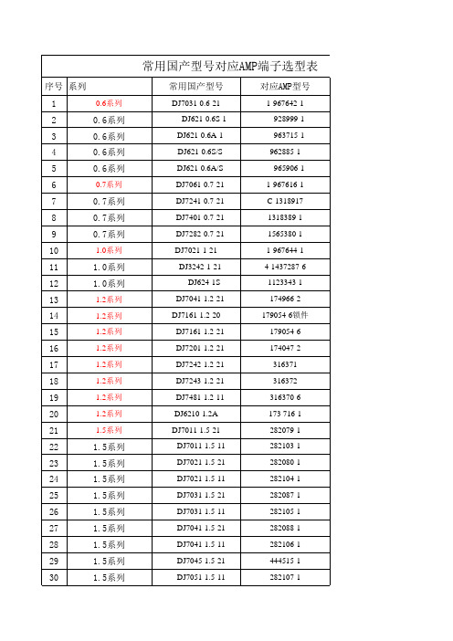
0.6系列DJ7031-0.6-21 1-967642-1(AMP安普号)DJ621-0.6S-1 928999-1(AMP安普号)DJ621-0.6A-1 963715-1(AMP安普号)DJ621-0.6S/S 962885-1(AMP安普号)DJ621-0.6A/S 965906-1(AMP安普号)0.7系列DJ7061-0.7-21 1-967616-1(AMP安普号)DJ7241-0.7-21 C-1318917(AMP安普号)DJ7401-0.7-21 1318389-1(AMP安普号)DJ7282-0.7-21 1565380-1(AMP安普号)1.0系列DJ7021-1-21 1-967644-1(AMP安普号)DJ3241-1-21 4-1437287-5(AMP安普号)DJ3242-1-21 4-1437287-6(AMP安普号)DJ7161-1-11 174053-2(AMP安普号)DJ624-1S 1123343-1(AMP安普号)1.2系列DJ7041-1.2-21 174966-2(AMP安普号)DJ7161-1.2-20 179054-6锁件(AMP安普号)DJ7161-1.2-21 179054-6(AMP安普号)DJ7201-1.2-21 174047-2(AMP安普号)DJ7242-1.2-21 316371(AMP安普号)DJ7243-1.2-21 316372(AMP安普号)DJ7481-1.2-11 316370-6(AMP安普号)DJ6210-1.2A 173 716-1(安普号) 173 681-1(AMP安普号)1.5系列DJ7011-1.5-21 282079-1(AMP安普号)DJ7011-1.5-11 282103-1(AMP安普号)DJ7021-1.5-21 282080-1(AMP安普号)DJ7021-1.5-11 282104-1(AMP安普号)DJ7031-1.5-21 282087-1(AMP安普号)DJ7031-1.5-11 282105-1(AMP安普号)DJ7041-1.5-21 282088-1(AMP安普号)DJ7041-1.5-11 282106-1(AMP安普号)DJ7045-1.5-21 444515-1(AMP安普号) 1717892-1(AMP安普号)DJ7051-1.5-21 282089-1(AMP安普号)DJ7051-1.5-11 282107-1(AMP安普号)DJ7061-1.5-21 282090-1(AMP安普号)DJ7061-1.5-11 282108-1(AMP安普号)DJ623-E1.5A 962 876-1(AMP安普号)DJ611-1.5×0.8A 282 109-1(AMP安普号)1.8系列DJ7022-1.8-11 348794-3(AMP安普号)DJ7042-1.8-21 174922-1(AMP安普号) 368501-1(AMP安普号)DJ7044-1.8-21 444046-1(AMP安普号)DJ7163-1.8-21 179631-1(AMP安普号)DJ7201-1.8-11 174936-1(AMP安普号)DJ7201-1.8-21 174952-1(AMP安普号) 368511-1(AMP安普号)DJ7023-1.8-21 348793-3(AMP安普号)DJ7063-1.8-21 174923-1(AMP安普号)DJ7033-1.8-21 174921-1(AMP安普号)DJY7201-1.8-11 175785-1(AMP)DJ614-G1.8A 173 645-1(AMP安普号)DJ624C-1.8A 282438-1(AMP安普号)DJ624C-1.8B 282 466-1(AMP安普号)DJ624B-1.8B 776 001-1(AMP安普号)DJ624-G1.8A 173 631-1(AMP安普号)DJ624-1.8A 282403-1(AMP安普号)2系列DJ7026-2-21 174352-2(AMP安普号)DJ7026-2-20 174353-7(AMP安普号)DJ7026-2-11 174354-2(AMP安普号)DJ7026-2-10 174355-7(AMP安普号)DJ7166-2-20 368049-1(AMP安普号)DJ7166-2-21 368047-1(AMP安普号)DJ3021-2-21 353377-7(AMP安普号)DJ3021-2-21-1 353378-2(AMP安普号)DJ7106-2-21 174655-2(AMP安普号)DJ623-2×0.6A 171 662-1(AMP安普号) 184030-3(AMP安普号)DJ613-2×0.6A 171 661-1(AMP安普号) 171631-1(AMP安普号)2.2系列DJ7063-2.2-20 936269-1(AMP安普号)DJ7063-2.2-21 936268-1(AMP安普号)DJ7163-2.2-10/20 936203-1(AMP安普号)DJ7163-2.2-11 936211-1(AMP安普号)DJ7163-2.2-21 936201-1(AMP安普号)DJ7163-2.2-11装配体936211-1(AMP安普号)DJ627-2.2X0.6A 368084-1(AMP安普号)DJ627-2.2X0.6S 368085-1(AMP安普号)2.8系列DJ613-2.8×0.8A 962880-2(AMP安普号)DJ616-2.8×0.8A 962883-2(AMP安普号)DJ616-2.8×0.8B 962884-2(AMP安普号)LC968H.1.1-4 962841-1(AMP安普号)DJ614-2.8*0.8A 142754-1(AMP安普号)3系列DJ7021-3-21 610207-5(AMP安普号)DJ7112-3-21 0-144521-4(AMP安普号)DJ7092-3-21 0-144520-2(AMP安普号)DJ7052-3-21 0-144518-1(AMP安普号)DJ7251-3-11 827535-1(AMP安普号)DJ6232-E3A 925590-1(AMP安普号)3.5系列DJ7023-3.5-21 282189-1(AMP安普号)DJ7024-3.5-11 357 972 762 929741-5(AMP安普号)DJ7031-3.5-21 443 906 233 828840-1(AMP安普号)DJ7031A-3.5-21 282246-1(AMP安普号)DJ7033-3.5-21 282191-1(AMP安普号)DJ7041K-3.5-21 144998-5(AMP安普号)DJ7043-3.5-21 282192-1(AMP安普号)DJ7551-3.5-21外壳282092-1(AMP安普号) 85214-1(AMP安普号) DJ7553-3.5-21外壳963534-1(AMP安普号) 1-85121-1(AMP安普号) DJ7082A-3.5-21 962189-1(AMP安普号)DJ623B-E3.5A-1 964284-2(AMP安普号)DJ623B-E3.5B-1 965999-2(AMP安普号)DJ611-3.5A 928 781-1(AMP安普号)DJ623-E3.5A/S 185 026-1(AMP安普号)DJ623-E3.5B/S 185 027-1(AMP安普号)DJ623-E3.5A/S镀金2-964 286-1(AMP安普号)DJ623C-E3.5S 0-0964280-2(AMP安普号)DJ623C-E3.5S/S 0-0964282-2(AMP安普号)DJ623C-E3.5C 0-0965999-2(AMP安普号)DJ623C-E3.5C/S 0-0964273-2(AMP安普号)4.0系列DJ7021-4-25 142680-4(AMP安普号)4.8系列DJ622-D4.8B 54-01 60430-7(AMP安普号)DJ615-4.8×0.8B 962904-2(AMP安普号)6系列DJ7023-6-21 MG610263(KET)DJ7012-6-11 174195-1(AMP安普号)DJ7012-6-21 172128-2(AMP安普号)DJ7022-6-11 172129-2(AMP安普号)DJ7022-6-21 172130-2(AMP安普号)DJ626-D6B 170 032-1(AMP安普号)6.3系列DJ7019-6.3-21 180984-1(AMP安普号)DJ7022-6.3-21 174198-1(AMP安普号)DJ7068-6.3-21 174204-1(AMP安普号)DJ624-D6.3B 927854-2(AMP安普号)DJ624-D6.3C 154 717-1(AMP安普号)DJ624- D6.3A 0-0927852-2(AMP安普号)DJ6218-E6.3A 964324-1(AMP安普号)DJ6218-E6.3B 969042-1(AMP安普号)DJ6218-E6.3C 964328-1(AMP安普号)DJ628-6.3B 963887-2(AMP安普号)DJ6210-6.3B 170454-1(AMP安普号)DJ6211-6.3B 171632-1(AMP安普号)DJ626-6.3B 170032-5(AMP安普号)DJ6232-E6.3A 927847-2(AMP安普号)DJ612-6.3B 0-0928962-3(AMP安普号)DJ627-D6.3(0.5~1.0平方线) 160861-1(AMP安普号) DJ628A-6.3B 963887-2(AMP安普号)DJ627-D6.3B 2-0180464-1(AMP安普号)DJ622-D6.3B 140760-4(AMP安普号)DJ621-A6.3A 160870-3(AMP安普号)DJ621-A6.3B 160824-6(AMP安普号)8系列DJ7022A-8-11 1544459-2(AMP安普号)DJ7022C-8-11 1544459-1(AMP安普号)DJ7022B-8-11 1544459-3(AMP安普号)9.5系列DJ221-2S 353376-3(AMP安普号)DJ221-1S 1437284-9(AMP安普号)复合系列DJ7811-1.2/3.5-21-1 368290-1(AMP安普号)DJ7811-1.2/3.5-21-3 368333-1(AMP安普号)DJ7811-1.2/3.5-21-4 368293-1(AMP安普号)DJ7811-1.2/3.5-21-5 368294-1(AMP安普号)DJ7811-1.2/3.5-21-6 368297-1(AMP安普号)DJ7161-1.8/2.8-11 967376-2(AMP安普号)DJ7161-2.3/6.3-21 368454-1(AMP安普号)DJ7181-2.3/6.3-21 368497-1(AMP安普号) DJ7201-2.3/6.3-21 368457-1(AMP安普号) 线卡系列JZ-XK-10 345484-1(AMP安普号) 密封堵系列MFD003-2 828905-1(AMP安普号)MFD006-4 828904-1(AMP安普号)MFD005-4 963293-1(AMP安普号)MFD001-8 963530-1(AMP安普号)杂件系列1393449-1 1-1393449-1(AMP安普号)JB214 284352-1(AMP)。
信捷伺服常见问题分析及解答
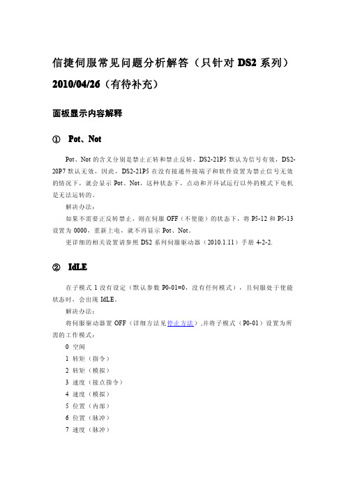
信捷伺服常见问题分析解答(只针对DS2系列)2010/04/26(有待补充)面板显示内容解释①Pot、NotPot、Not的含义分别是禁止正转和禁止反转,DS2-21P5默认为信号有效,DS2-20P7默认无效,因此,DS2-21P5在没有接通外接端子和软件设置为禁止信号无效的情况下,就会显示Pot、Not,这种状态下,点动和开环试运行以外的模式下电机是无法运转的。
解决办法:如果不需要正反转禁止,则在伺服OFF(不使能)的状态下,将P5-12和P5-13设置为0000,重新上电,就不再显示Pot、Not。
更详细的相关设置请参照DS2系列伺服驱动器(2010.1.11)手册4-2-2.②IdLE在子模式1没有设定(默认参数P0-01=0,没有任何模式),且伺服处于使能状态时,会出现IdLE。
解决办法:将伺服驱动器置OFF(详细方法见停止方法),并将子模式(P0-01)设置为所需的工作模式:0空闲1转矩(指令)2转矩(模拟)3速度(接点指令)4速度(模拟)5位置(内部)6位置(脉冲)7速度(脉冲)③bb、runbb表示伺服驱动器处于停止(未使能)状态,run表示伺服驱动器处于运行(使能)状态。
④EEEEx表示显示面板与数字处理器通讯不畅。
伺服使能与停止①伺服使能a,默认情况下(P5-10=0001),给伺服驱动器的第一个信号输入端一个导通信号,具体的接线方式为,电源的24V接到伺服驱动器的+24V,电源的0V通过开关接到SI1.b,如果需要上电使能,则将P5-10设置为0010,重新上电后有效。
②伺服停止a,将外部使能信号断开,并将外接IO端子拆除;b,将P5-10设置为0001,然后重新上电;c,以上两个步骤均无效的情况下,查看U-22,若第5个数码管的第一横亮,则说明CPU板的输入端子出现短路(需要返修)。
参数无法修改部分参数在伺服处于使能状态时,是不能进行更改的,恢复出厂也无效,如果需要修改,就要先将伺服驱动器置OFF。
AMP(安普)2011产品手册

序号产品型号编号单位产品描述AMP 六类非屏蔽1六类4对非屏蔽双绞电缆1427254-6箱蓝色,305米/箱,防火等级CM2六类4对非屏蔽双绞电缆9-1427200-6箱蓝色,305米/箱,防火等级CMR3六类4对非屏蔽双绞电缆219585-2箱白色,305米/箱,防火等级LSZH4六类4对非屏蔽信息模块8-1375055-x个1=浅杏黄色 -3=白色 -5=橙色 -7=红色 -8=黄色 -9=绿色 SL免工具5六类非屏蔽24口配线架1375014-2个高度1U,平面型,非屏蔽6六类非屏蔽48口配线架1375015-2个高度2U,平面型,非屏蔽7六类非屏24口蔽角型配线架1499600-2个高度1U,角型,非屏蔽8六类非屏蔽跳线(4FT)1859246-4条灰色,防火等级CM9六类非屏蔽跳线(7FT)1859246-7条灰色,防火等级CM10六类非屏蔽跳线(10FT)1859246-1-0条灰色,防火等级CMAMP 六类屏蔽1六类屏蔽双绞线1859204-6箱蓝色,305/轴,250MHZ,防火等级CM2六类屏蔽双绞线1427213-1箱白色,305/轴,250MHZ,防火等级LSZH3六A类屏蔽双绞线1859222-2箱白色,305/轴,250MHZ,防火等级CM4六A类屏蔽双绞线1859218-2箱白色,305/轴,250MHZ,防火等级LSZH5六A类屏蔽24口配线架1933319-2个高度1U,平面型,屏蔽6六A类屏蔽24口角型配线架1933321-2个高度1U,角型,屏蔽7屏蔽24口平面型配线空架1933307-1个高度1U,平面型,屏蔽8屏蔽24口角型配线空架1933309-1个高度1U,角型,屏蔽9六类屏蔽信息模块1479552-1个六类SL型屏蔽模块,从侧面90°进线10六类屏蔽信息模块8-1375188-1个六类SL型屏蔽模块,从后面180°进线11六A类屏蔽信息模块1711160-2个六类SL型屏蔽模块,从后部入线,带防尘盖12六A类屏蔽信息模块1711342-2个六类SL型屏蔽模块,从后部入线,不带防尘盖13六类屏蔽跳线(1米)1427226-5条灰色1859300,粉红色1859293,防火等级CM14六类屏蔽跳线(2米)1427226-6条灰色1859300,粉红色1859293,防火等级CM15六类屏蔽跳线(3米)1427226-7条灰色1859300,粉红色1859293,防火等级CM16六类屏蔽跳线(5米)1427226-8条灰色1859300,粉红色1859293,防火等级CMAMP超五类非屏蔽。
湖北三环轻卡创客国五车型介绍

一、创客物流项目 二、创客自卸项目
车身介绍 --外观造型
车身造型传承 T380 经典 设计,大气美观,顔值高
立式组合水晶大灯
最大外宽1995mm,内部
空间宽敞,乘坐舒适
直立化 A柱和侧围设计, 视野更开阔。配合导流罩 ,有效减少空气阻力,降 低燃油消耗。
1995mm
车身介绍 --框架式后视镜
2
T3车型 C16B14×2物 P003/P 流 004
3300
T3单排 空调、动转、 (1995) 万里扬 1061 80L(全 离合助力、断 4150mm ISF3.8 2.2 4.2T/4 1061 192(6局部 7.5R16 /T3排 6T50高 (10+7 钢)130 气刹、感载阀、 /3800m s5141 T .875 (8/11) 加强) 全钢 半 速 /11+9) 油箱 干燥器、排气 m底盘 (1995) 制动
上装优势介绍
前飞机梁采用槽钢扣焊, 行驶稳定性更强
160幅面槽钢内扣底座
后内四翻 翻转结构
上装优势介绍
举升方式: Φ110双顶(三节缸)、Φ160单顶两种选择
重要卖点提炼
高强钢货厢 结构 后悬减震设 计 标配夹胶玻璃, 更上档次 框架式后视镜 ,视野更开阔
接插件5557接口标准

接插件5557接口标准一、引言接插件是电子设备中常用的连接器件,用于在不同的电子设备之间传输数据和电信号。
接插件5557接口是一种常见的接口标准,广泛应用于各种电子设备中。
本文将对接插件5557接口标准进行详细介绍。
二、接插件5557接口标准概述接插件5557接口标准是一种采用全金属外壳的电子插头接口标准。
它具有以下特点:1.外壳材质:接插件5557接口标准采用全金属外壳,具有良好的电磁屏蔽性能和耐久性。
2.接口类型:接插件5557接口标准为插销接插方式,方便快捷。
3.电路特性:接插件5557接口标准支持多种电路连接方式,如并行连接和串行连接。
4.通信速率:接插件5557接口标准支持高速通信,可以实现高达1000Mbps的数据传输速率。
5.防护等级:接插件5557接口标准具有较高的防护等级,可以在恶劣环境下使用。
三、接插件5557接口标准详解1.外壳结构:接插件5557接口标准的外壳由两部分组成,包括插座外壳和插头外壳。
插座外壳一般安装在设备上,插头外壳则连接在电缆上,两者可以通过插销连接起来。
2.引脚定义:接插件5557接口标准共有6个引脚,分别为A、B、C、D、E、F。
各个引脚的功能如下:-引脚A:用于信号传输。
-引脚B:用于信号传输。
-引脚C:用于信号地线连接。
-引脚D:用于信号地线连接。
-引脚E:用于供电连接。
-引脚F:用于供电连接。
3.电路连接方式:接插件5557接口标准支持多种电路连接方式。
可以通过并行连接方式实现多个设备间的快速数据传输,也可以通过串行连接方式实现长距离数据传输。
4.通信速率:接插件5557接口标准支持高速通信,可以实现高达1000Mbps的数据传输速率。
这使得它在现代电子设备中广泛应用,特别适用于需要高速数据传输的场景。
5.防护等级:接插件5557接口标准具有较高的防护等级,可以在恶劣环境下使用。
它可以有效抵御各种外界干扰,确保数据传输的可靠性。
四、应用领域接插件5557接口标准广泛应用于各种电子设备中,包括计算机、网络设备、仪器仪表、通信设备等。
AMP连接器培训文档

AMP连接器培训文档一、AMP连接器的基础知识二、AMP连接器的寻找三、AMP连接器的销售一、AMP连接器的基础知识1、TYCO/AMPTYCO世界上最大的无源电子元器件供应商.在2005年的世界500强企业排行里面是在103位TYCO 99年收购美国AMP公司也是目前收购最大的一家企业。
其每年的销售额为三百多亿美金2、AMP连接器(接插件)优势AMP连接器在连接器行业是世界第一品牌。
其要紧产品是表达在汽车行业上,没有任何一家企业(Molex、JST、YAZAKI…)做的有AMP连接器这样全面,能够说设计到了每一个角落目前除了一些日系车与农用、工程、大巴会用的少一点,其它90%都用的是AMP连接器汽车工业产品现目前都是在美国生产、目前在苏州投资了5000万美金专门生产AMP汽车工业产品(东莞有2个生产基地、深圳2个、中山、佛山、顺德、各一个。
上海4个、苏州一个只做AMP汽车,投资5000万美金)AMP连接器的品质重点表达其载流量、稳固性、耐高温、密封性、抗震抗冲击性好3、AMP连接器涉及的行业1、汽车2、航空、航天与军事防御3、通讯设备4、工业与商用设备5、电力6、外部通信设备7、综合布线8、有连接的地方就有AMP连接器4、AMP连接器的结构连接器的基本结构件有①接触件;②绝缘体;③外壳(视品种而定);④附件2.绝缘体绝缘体也常称之基座(base)或者安装板(insert),它的作用是使接触件按所需要的位置与间距排列,并保证接触件之间与接触件与外壳之间的绝缘性能。
良好的绝缘电阻、耐电压性能与易加工性是选择绝缘材料加工成绝缘体的基本要求5、连接器的基本性能三大指标:①机械性能;②电气性能;③环境性能1.连接器的插拔力与机械寿命与接触件结构(正压力大小)接触部位镀层质量(滑动摩擦系数)与接触件排列尺寸精度(对准度)有关2.电气性能连接器的要紧电气性能包含接触电阻、绝缘电阻与抗电强度②绝缘电阻衡量电连接器接触件之间与接触件与外壳之间绝缘性能的指标,其数量级为数百兆欧至数千兆欧不等③抗电强度或者称耐电压、介质耐压,是表征连接器接触件之间或者接触件与外壳之间耐受额定试验电压的能力对射频同轴连接器而言,还有特性阻抗、插入损耗、反射系数、电压驻波比(VSWR)等电气指标。
AMP connector
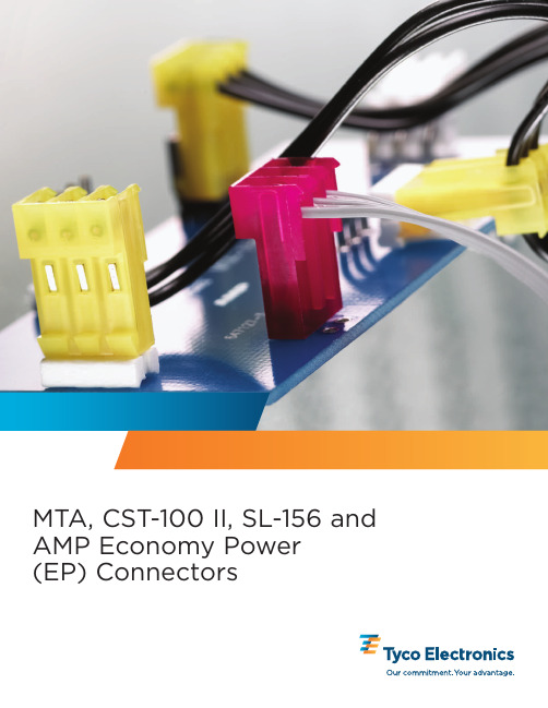
MTA,CST-100II,SL-156and AMP Economy Power(EP)Connectors2©1977,1978,1979,1980,1983,1986,1988,1992,1993,1994,1995,1999,2000,2001,2002,2003and2005byTyco Electronics Corporation.All International Rights Reserved.AMP,AMP-O-LECTRIC,AMP-O-MATIC,AMPOMATOR,CERTI-CRIMP,PRO-CRIMPER,MADISON CABLE andTYCO are trademarks.TEFLON is a trademark of E.I.DuPontDe Nemours and Company.Other products,logos,and companynames mentioned herein may betrademarks of their respective owners.Introduction and Table of Contents.................................................2,3Connector Selection Guide (3).050[1.27]Centerline ConnectorsMTA-50IDC Connectors and Headers............................................4-10Introduction and Wire-to-Board Mateability Guide (4)IDC Connector Kits(Feed-Thru and Closed End)Ribbon Cable.......................................................5,6Discrete Wire........................................................7,8Through-Hole Header AssembliesVertical and Right-Angle (9)Surface Mount Header AssembliesVertical and Right-Angle (10).100[2.54]Centerline ConnectorsMTA-100IDC Connectors and Headers..........................................11-31Introduction (11)Wire-to-Board Mateability Guide.........................................12,13Connectors—UL94V-2and UL94V-0Closed End with and without Polarizing Tab.............................14,15Feed-Thru with and without Polarizing Tab..............................14,15LED Closed End and Feed-Thru—UL94V-2.............................14,15Accessories.........................................................16,17Posted Connectors Mateability Guide....................................18,19MTA-100Posted Connectors(Wire-to-Wire)UL94V-2Closed End (20)Feed-Thru (20)Headers—UL94V-0Flat—Straight and Right-Angle Posts (21)Narrow Flat—Straight and Right-Angle Posts (22)Polarized—Straight and Right-Angle Posts (23)Friction Lock—Straight and Right-Angle Posts (24)Headers with Retention Peg—Straight Posts (25)High Profile Headers—Right-Angle Posts (26)Polarized—High Temperature,Straight and Right-Angle Posts (27)Friction Lock—High Temperature,Straight and Right-Angle Posts (28)Polarized—Surface Mount,Straight (29)Friction Lock—Surface Mount,Straight (29)Shrouded—Straight and Right-Angle Posts (30)CST-100II Crimp Contacts,Housings and Shrouded Headers.........................31,32.156[3.96]Centerline ConnectorsMTA-156IDC Connectors and Headers..........................................33-57Introduction (33)Wire-to-Board Mateability Guide.........................................34,35Connectors—UL94V-2and UL94V-0Closed End with Locking Ramp,with and without Polarizing Tabs...........36,37Closed End without Locking Ramp,with and without Polarizing Tabs.........36,37Feed-Thru with Locking Ramp,with and without Polarizing Tabs.............38,39Feed-Thru without Locking Ramp,with and without Polarizing Tabs...........38,39Accessories.........................................................40-42Posted Connectors Mateability Guide....................................43,44MTA-156Posted Connectors(Wire-to-Wire)—UL94V-2Closed End (45)Feed-Thru (45)MTA-156Headers—UL94V-0Flat—Straight Posts (46)Flat—Right-Angle Posts (47)Friction Lock—Straight Posts (48)Friction Lock—Right-Angle Posts (49)Polarized Lock—Straight Posts (50)Polarized Lock—Right-Angle Posts (51)Friction Lock—High Temperature,Straight Posts (52)Shrouded—Straight and Right-Angle Posts (53)MTA-156Quad Connectors—UL94V-0.........................................54,55Closed End with Locking Ramp (55)Feed-Thru with Locking Ramp (55)IDCMTA-50IDCMTA-100CrimpCST-100IIIDCMTA-156Catalog82056Dimensions are in inches and Dimensions are shown for USA:1-800-522-6752South America:55-11-2103-6000 Revised6-08millimeters unless otherwise reference purposes only.Canada:1-905-470-4425Hong Kong:852-2735-1628 specified.Values in brackets Specifications subject Mexico:52-55-1106-0800Japan:81-44-844-8013 are metric equivalents.to change. C.America:57-1-254-4444UK:44-208-420-83413MTA-156Card Edge .......................................................56,57Connectors —UL94V-0Closed End with and without Mounting Ears ................................56Feed-Thru with and without Mounting Ears .................................56Accessories ............................................................57SL-156Crimp Connectors and Headers .........................................58-62Wire-to-Board Mateability Guide ............................................58Wire-to-Board Crimp Contacts and Keying Plugs ...............................59Wire-to-Board Housings —UL94V-0.........................................60Housings with Through Board Latch —UL94V-2...............................61Housings and Contacts for Large Insulation Diameter (LID)Wire ..................62AMP Economy Power (EP)Connector System .......................................63-69.156[3.96]Centerline ConnectorsIntroduction ............................................................63Crimp Contacts .........................................................64Plug Housings,Low-Profile ................................................64Low-Profile Headers —Straight and Right-Angle Posts ..........................65Low-Profile Headers,High Temp.—Straight and Right-Angle Posts ...............66.200[5.08]Centerline ConnectorsPlug Housings and Straight and Right-Angle Post Headers ......................67.312[7.92]Centerline ConnectorsLow-Profile Headers —Straight Posts .......................................68Single Connectors1-Position Plug Housing and High-Profile Header —Straight Post .................69MTA Wire Selection and Ribbon Cable Preparation ......................................70IDC Ribbon Cable ...........................................................71-74MTA Wire Termination Flowchart ...................................................75MTA Application Tooling .......................................................76-79Part Number Index ...........................................................80-82Global Contacts (83)Need more information?Call T echnical Support at the numbers listed below.T echnical Support is staffed with specialists well versed in Tyco Electronics products.They can provide you with:I Technical support I CatalogsI Technical Documents I Product SamplesI Authorized Distributor LocationsCrimpSL-156CrimpAMP EP ConnectorsCatalog 82056Dimensions are in inches and Dimensions are shown for USA:1-800-522-6752South America:55-11-2103-6000Revised 6-08millimeters unless otherwise reference purposes only.Canada:1-905-470-4425Hong Kong:852-2735-1628specified.Values in brackets Specifications subject Mexico:52-55-1106-0800Japan:are metric equivalents.to change.C.America:57-1-254-4444UK:44-208-420-83414M T A -50.050[1.27]Component Recognized Underwriters Inc.to US and Standards,File No.E28476(Connectors and Headers)File No.E53793(Ribbon Cable)The MTA-50IDC Connector System is a wire-to-printed cir-cuit board system with con-tacts in a staggered,single row on .050[1.27]centerline.The design features wire feed-through capability for daisy-chain applications.Insulation displacement contacts are used to terminate a wide range of conductor sizes.Ribbon cable can also be ter-minated when the appropriate receptacle assembly and strain relief cover are used.Header assemblies for board mount applications include right-angle (horizontal)and vertical mount products.These are available inthrough-hole and surface mount configurations.Typical uses of the MTA-50IDC connectors would be in the Appliance,Commercial and Home Equipment and Security products industries.See thefollowing pages for related products:I Ribbon Cable (reels),.050[1.27]centerline (p.71)I Application T ooling (p.76)I Cable Assemblies (p.74)Performance DataVoltage Rating —30VAC Current Rating —1amp max.Low-Level Resistance —30milliohmsDielectric Withstanding Voltage —500VACInsulation Resistance —1,000megohmsOperating Temperature —–55°C to +105°C for connector only;cable rating may be lowerTechnical DocumentsApplication Specification —114-13072MTA-50Connectors Product Specifications —108-2113MTA-50Connectors 100-4703MADISON CABLE CableSpecification (28AWG,7/36Tinned copper,PVC insulation)100-6257MADISON CABLE CableSpecification (28AWG,7/36Tinned copper,TPO insulation)These matrixes have been prepared to assist you in defining the correct mating halves for the MTA-50header and connector kit combina-tion.Where a “Y”is indicated the combination is a valid mating pair.Note:T yco Electronics does NOT rec-ommend intermating connectors and headers with different contact plat-ings.C o n n e c t o r K i t sHeaders C o n n e c t o r K i t sMatrix for .000030[0.00076]Gold Plated Part NumbersC o n n e c t o r K i t sMatrix for .000015[0.00038]Gold Plated Part NumbersMatrix for Tin Plated Part Numbers HeadersHeadersMTA-50IDC Connector Kit /Header Mateability GuideCatalog 82056Dimensions are in inches and Dimensions are shown for USA:1-800-522-6752South America:55-11-2103-6000Revised 6-08millimeters unless otherwise reference purposes only.Canada:1-905-470-4425Hong Kong:852-2735-1628specified.Values in brackets Specifications subject Mexico:52-55-1106-0800Japan:are metric equivalents.to change.C.America:57-1-254-4444UK:44-208-420-83415MTA-50.050[1.27]Connector Kits —Ribbon CableFeed-Thru andClosed End ConnectorsMaterial and FinishHousing —UL 94V-2rated,thermo-plasticContacts —Phosphor bronze;.000100[0.00254]min.tin in wiretermination area,over.000050[0.00127]min.nickel;choice on mating end:.000100[0.00254]min.tin or .000030[0.00076]gold or .000015[0.00038]gold,over .000050[0.00127]min.nickelColor Coding by Wire Size for UL94V-0Connectors26AWG —Blue 28AWG —Green 30AWG —BrownFor Strain Relief Covers see page 6.For mating Headers see pages 9and 10.For Mateability Guide,see matrixes on page4..050[1.27].035[0.89]]Ref.Position 1.150[3.81]Notes:1.To determine connector overall length (dim.A),multiply .050x the number of circuits and add .082.Example:.050x 10circuitsequals 0.50+.082=.582[14.78].2.Strain relief covers shown on page 6are required and sold as part of the Connector Kit.3.Stranded UL Style 1061or equiv-alent wire is recommended.4.Unless otherwise stated all toler-ances (except plating)to be ±.005[±0.13].5.Consult Product Drawing for RoHS Compliant information.Note:Tin-plated connectors and headers in even position sizes from 2–12and 18are stocked parts;all other position sizes and products with gold-plated contacts are Make T o Order.Receptacle Assemblies —Ribbon CableCatalog 82056Dimensions are in inches and Dimensions are shown for USA:1-800-522-6752South America:55-11-2103-6000Revised 6-08millimeters unless otherwise reference purposes only.Canada:1-905-470-4425Hong Kong:852-2735-1628specified.Values in brackets Specifications subject Mexico:52-55-1106-0800Japan:are metric equivalents.to change.C.America:57-1-254-4444UK:44-208-420-83416M T A -50.050[1.27].090[2.29]4Plcs.AStrain ReliefCoversMaterial and FinishStrain Relief Cover —UL 94V-0rated,thermoplastic,blackClosed EndFeed-Thru and Closed EndDim.A No.of CircuitsDim.161718.2606.60.3107.87.3609.14Closed End[3.12AFeed-ThruFeed-ThruConnector Kits —Ribbon Cable (Continued)Catalog 82056Dimensions are in inches and Dimensions are shown for USA:1-800-522-6752South America:55-11-2103-6000Revised 6-08millimeters unless otherwise reference purposes only.Canada:1-905-470-4425Hong Kong:852-2735-1628specified.Values in brackets Specifications subject Mexico:52-55-1106-0800Japan:are metric equivalents.to change.C.America:57-1-254-4444UK:44-208-420-83417MTA-50.050[1.27]Connector Kits —Discrete WireFeed-Thru andClosed End ConnectorsMaterial and FinishHousing —UL 94V-2rated,thermo-plasticContacts —Phosphor bronze;.000100[0.00254]min.tin in wiretermination area,over.000050[0.00127]min.nickel;choice on mating end:.000100[0.00254]min.tin or .000030[0.00076]gold or .000015[0.00038]gold,over .000050[0.00127]min.nickelColor Coding by Wire Size for UL94V-0Connectors26AWG —Blue 28AWG —Green 30AWG —BrownFor Strain Relief Covers see page 8.For mating Headers see pages 9and 10.For Mateability Guide,see matrixes on page4..050[1.27].035[0.89]]Ref.Position 1.150[3.81].006 0.15]Notes:1.To determine connector overall length (dim.A),multiply .050x the number of circuits and add .082.Example:.050x 10circuitsequals 0.50+.082=.582[14.78].2.Strain relief covers shown on page 8are required and sold as partofthe Connector Kit.3.Stranded UL Style 1061or equiv-alent wire is recommended.4.Unless otherwise stated all toler-ances (except plating)to be ±.005[±0.13].5.Consult Product Drawing for RoHS Compliant information.Note:Tin-plated connectors and headers in even position sizes from 2–12and 18are stocked parts;all other position sizes and products with gold-plated contacts are Make T o Order.Receptacle Assemblies —Discrete WireCatalog 82056Dimensions are in inches and Dimensions are shown for USA:1-800-522-6752South America:55-11-2103-6000Revised 6-08millimeters unless otherwise reference purposes only.Canada:1-905-470-4425Hong Kong:852-2735-1628specified.Values in brackets Specifications subject Mexico:52-55-1106-0800Japan:are metric equivalents.to change.C.America:57-1-254-4444UK:44-208-420-83418M T A -50.050[1.27]Strain Relief CoversMaterial and FinishStrain Relief Cover —UL 94V-0rated,thermoplastic,blackClosed EndDim.A No.of CircuitsDim.161718.2606.60.3107.87.3609.14Feed-Thru and Closed EndFeed-Thru.090[2.29]4Plcs.AClosed End.123 [3.12AFeed-ThruConnector Kits —Discrete Wire (Continued)Catalog 82056Dimensions are in inches and Dimensions are shown for USA:1-800-522-6752South America:55-11-2103-6000Revised 6-08millimeters unless otherwise reference purposes only.Canada:1-905-470-4425Hong Kong:852-2735-1628specified.Values in brackets Specifications subject Mexico:52-55-1106-0800Japan:are metric equivalents.to change.C.America:57-1-254-4444UK:44-208-420-83419MTA-50.050[1.27]Right-AngleA.125[3.18].016 [0.41].050[1.27]Ref.Ref.Ref.Circuit #1.180 [4.57][5.59±0.08].035[0.89]Ref.VerticalMaterial and FinishHousing —UL 94V-0rated,thermo-plastic,blackContacts —Brass,.000100[0.00254]min.tin over.000050[0.00127]min.nickel on solder legs;choice on mating end:.000100[0.00254]min.tin or .000030[0.00076]gold or .000015[0.00038]gold,over .000050[0.00127]min.nickel#1ABase Part NumbersThrough-Hole Header No.of Part Nos.PostsStandard UL 94V-0,Tin Plated14451202–28Standard UL 94V-0.000030[0.00076]Gold Plated14451252–28Standard UL 94V-0.000015[0.00038]Gold Plated14451232–28Note:To determine header overalllength (dim.A),multiply .050x the number of circuits and add .150.Example:.050x 6circuits equals .300+.150=.450[11.43]..100[2.54].035[0.89].210[5.33].050[1.27].250*[6.35].031±.002[0.78±0.05Circuit #1Typ.Recommended Mounting Hole Size andPattern for .062[1.57]Thick PC BoardDim.shown,refer to Product Drawing for Dimensions and RoHS Compliant information.Base Part NumbersThrough-Hole Header Part Nos.Standard UL 94V-0,1445169Standard UL 94V-0.000030[0.00076]Gold 1445171Standard UL 94V-0.000015[0.00038]Gold 1445170For mating Connector Kits see pages 5through 8.For mateability options,see matrixes on page 4.Note:Tin-plated connectors and headers in even position sizes from 2–12and 18are stocked parts;all other position sizes and products with gold-plated contacts are Make T o Order.Through-Hole Header Assemblies Catalog 82056Dimensions are in inches and Dimensions are shown for USA:1-800-522-6752South America:55-11-2103-6000Revised 6-08millimeters unless otherwise reference purposes only.Canada:1-905-470-4425Hong Kong:852-2735-1628specified.Values in brackets Specifications subject Mexico:52-55-1106-0800Japan: are metric equivalents.to change.C.America:57-1-254-4444UK:44-208-420-834110M T A -50.050[1.27]Right-AngleVerticalMaterial and FinishHousing —UL 94V-0rated,thermo-plastic,blackContacts —Brass,.000100[0.00254]min.tin over.000050[0.00127]min.nickel on solder pads;choice on mating end:.000100[0.00254]min.tin or .000030[0.00076]gold or .000015[0.00038]gold,over .000050[0.00127]min.nickelBoardlock —Phosphor bronze,tin plated .000100[0.000254]min.over .000050[0.00127]min.nickel.035[0.89]Ref.Circuit #1A.249[6.32].003 0.08]Ref.For mating Connector Kits see pages 5through 8.For mateability options,see matrixes on page 4.Note:To determine header overalllength (dim.A),multiply .050x the number of circuits and add .150.Example:.050x 6circuits equals .300+.150=.450[11.43]..162[4.11]*6-circuit Dim.shown,refer to Product Drawing for actualPCB Dimensions and RoHS Compliant information..050[1.27]Circuit #1Typ..028 ±.001 [0.71 ±0.03].075±.001 [1.91±0.03] ].145±.003 [3.68±0.08].574*for use with .010[0.25] Thick StencilTyp.Base Part NumbersSurface Mount Header No.of Part Nos.PostsStandard UL 94V-0,Tin Plated14451722–28Standard UL 94V-0.000030[0.00076]Gold Plated14451742–28Standard UL 94V-0.000015[0.00038]Gold Plated14451732–28Base Part NumbersSurface Mount Header No.of Part Nos.PostsStandard UL 94V-0,Tin Plated14451212–28Standard UL 94V-0.000030[0.00076]Gold Plated14451262–28Standard UL 94V-0.000015[0.00038]Gold Plated14451242–28Note:All SMT product is pre-packaged in standard tape and reel format..162[4.11].574*[14.58][2.54].100[2.54]*6-circuit Dim.shown,refer to Product Drawing for actualPCB Dimensions and RoHS Compliant information..050[1.27]Circuit #1Typ..100[2.54]Typ.Typ.Typ..028±.001[0.71±0.03].065±.001 [1.65±0.03].070±[1.78±[3.68Recommended PC Board Layout for use with .010 [0.25] Thick StencilA.050[1.27].035[0.89]Ref.Ref.Circuit #1.270 [6.86][5.59±0.08]Ref.Note:Tin-plated connectors and headers in even position sizes from 2–12and 18are stocked parts;all other position sizes and products with gold-plated contacts are Make T o Order.Surface Mount Header AssembliesCatalog 82056Dimensions are in inches and Dimensions are shown for USA:1-800-522-6752South America:55-11-2103-6000Revised 6-08millimeters unless otherwise reference purposes only.Canada:1-905-470-4425Hong Kong:852-2735-1628specified.Values in brackets Specifications subject Mexico:52-55-1106-0800Japan:are metric equivalents.to change.C.America:57-1-254-4444UK:44-208-420-834111MTA-100.100[2.54]Technical DocumentsProduct Specification108-1050MTA-100Connectors Application Specifications 114-1019MTA-100Connectors 114-1031MTA-100Ribbon CableAssemblyMT A-100connectorsaccept discrete and ribbon cable wire sizes ranging from 22–28AWG [0.4–0.08mm 2]with maximum insulation outside diameter of .060[1.52]for terminat-ing single wire and .050[1.27]for mass termination of wires.Tin plated solid,fusedstranded,or stranded (7strands)wire with PVC insulation can be used on 22–28AWG [0.4–0.9mm 2]MTA-100connectors and 19stranded wire on22–24AWG [0.4–0.2mm 2]MTA-100connectors.OnlyPerformance Data*Voltage Rating —250vac Current Rating —5amp max.Low-Level Resistance —6m ⍀max.initialDielectric Withstanding Voltage —750vac/1min.Insulation Resistance —5000M ⍀min.initialOperating Temperature —Ϫ55ЊC to ϩ105ЊCNote:Refer to page 70for approved wire listings.one wire to be terminated into an IDC contact slot.The wire-to-post connector housing material is flame retardant thermoplastic,either UL94V-2or UL94V-0rated.A full line of .100[2.54]centerline headers com-pletes the system.Headers are available with straight or right-angle posts,in flat,polarized or friction lock styles.Headers are avail-able in 2through 28positions.Shrouded headers are available in 2through 14positions.*Refer to the Product Specification for additional electrical,mechanical and environmental performance tests and requirements.Catalog 82056Dimensions are in inches and Dimensions are shown for USA:1-800-522-6752South America:55-11-2103-6000Revised 6-08millimeters unless otherwise reference purposes only.Canada:1-905-470-4425Hong Kong:852-2735-1628specified.Values in brackets Specifications subject Mexico:52-55-1106-0800Japan:are metric equivalents.to change.C.America:57-1-254-4444UK:44-208-420-834112M T A -100.100[2.54]This matrix has been prepared to assist you,our customer,in defining the correct mating halves for the MT A-100header and connector combination.Where a “Y”is indicated the combination is a valid mating pair.Where an “N”is indicated the combination is not acceptable for mating.*Select contact plating to match header plating.HeadersC o n n e c t o r sMatrix for Tin Plated Part NumbersCatalog 82056Dimensions are in inches and Dimensions are shown for USA:1-800-522-6752South America:55-11-2103-6000Revised 6-08millimeters unless otherwise reference purposes only.Canada:1-905-470-4425Hong Kong:852-2735-1628specified.Values in brackets Specifications subject Mexico:52-55-1106-0800Japan:are metric equivalents.to change. C.America:57-1-254-4444UK:44-208-420-834113MTA-100.100[2.54]HeadersC o n n e c t o r sThis matrix has been prepared to assist you,our customer,in defining the correct mating halves for the MT A-100header and connector combination.Where a “Y”is indicated the combination is a valid mating pair.Where an “N”is indicated the combination is not acceptable for mating.Matrix for .000030[0.00076]Gold Plated Part NumbersHeadersC o n n e c t o r sMatrix for .000015[0.00038]Gold Plated Part Numbers*Select contact plating to match header plating.Catalog 82056Dimensions are in inches and Dimensions are shown for USA:1-800-522-6752South America:55-11-2103-6000Revised 6-08millimeters unless otherwise reference purposes only.Canada:1-905-470-4425Hong Kong:852-2735-1628specified.Values in brackets Specifications subject Mexico:52-55-1106-0800Japan:are metric equivalents.to change.C.America:57-1-254-4444UK:44-208-420-834114M T A -100.100[2.54]Material and FinishHousing —UL94V-2rated,nylon,see below for color;or UL94V-0rated,nylon,blackContacts —Phosphor bronze,post tin plated,.000030[0.00076]or .000015[0.00038]post gold-plated over nickelClosed End ConnectorsWithout Polarizing TabsWith Polarizing TabsWithout Polarizing TabsWith Polarizing TabsFeed-Thru ConnectorsColor Coding byWireSize for UL94V-2Connectors28AWG —Green 26AWG —Blue 24AWG —White 22AWG —RedAll wire sizes in UL94V-0—BlackFor mateability options,see matrix on pages 12and 13.For mating half visuals,see pages 20thru 30.Notes:1.Refer to pages 70-74for approved wire listing.2.For strain reliefs and dust covers,see page 16.3.For keying plugs,see page 17.4.Other circuit sizes are available upon request.Minimums may apply.5.Connector circuits can be molded closed for keying purposes.Minimums may apply.6.Where no part numbers appear in the chart,parts can be madeavailable upon request.Minimums may apply.7.T o determine connector overall length (dim.A),multiply .100x the number of circuits.Example:.100x 10circuits equals 1.000inch [25.4mm].Catalog 82056Dimensions are in inches and Dimensions are shown for USA:1-800-522-6752South America:55-11-2103-6000Revised 6-08millimeters unless otherwise reference purposes only.Canada:1-905-470-4425Hong Kong:852-2735-1628specified.Values in brackets Specifications subject Mexico:52-55-1106-0800Japan:are metric equivalents.to change.C.America:57-1-254-4444UK:44-208-420-834115MTA-100.100[2.54]Catalog 82056Dimensions are in inches and Dimensions are shown for USA:1-800-522-6752South America:55-11-2103-6000Revised 6-08millimeters unless otherwise reference purposes only.Canada:1-905-470-4425Hong Kong:852-2735-1628specified.Values in brackets Specifications subject Mexico:52-55-1106-0800Japan:are metric equivalents.to change.C.America:57-1-254-4444UK:44-208-420-834116M T A -100.100[2.54]CoversMaterial (RoHS Compliant)Strain Relief Cover —UL94V-2rated,nylon,whiteDust Covers —UL94V-0rated,polyester,whiteClosed End Strain Relief CoversClosed End Dust Coversmay or may not be present.Cover Ordering InformationThe “Base Part Numbers”Chart at right shows the base part number andnumber of circuits available for the described cover.Prefixes and suffixes are determined by the number of circuit positions in the cover.For example,the complete part number for a 10-position closed end strain relief cover would be:Base number 643075plusprefix-and-suffix1-—-0The correct ordering num-ber is1-643075-0Base Part Numbers6430752–286405502–286430772–286406423-28Cover LengthNo.of Dim.Prefix/Circuits A Suffix 2.200-25.083.300-37.624.400-410.165.500-512.76.600-615.247.700-717.788.800-820.329.900-922.8610 1.001--025.411 1.1001--127.9412 1.2001--230.4813 1.3001--333.0214 1.4001--435.56151.5001--538.116 1.6001--640.6417 1.7001--743.1818 1.8001--845.7219 1.9001--948.2620 2.0002--050.821 2.1002--153.34222.2002--255.88No.of Dim.Prefix/Circuits A Suffix No.of Dim.Prefix/Circuits A Suffix No.of Dim.Prefix/Circuits A Suffix 23 2.3002--358.4224 2.4002--460.9625 2.5002--563.526 2.6002--666.0427 2.7002--768.58282.8002--871.12Catalog 82056Dimensions are in inches and Dimensions are shown for USA:1-800-522-6752South America:55-11-2103-6000Revised 6-08millimeters unless otherwise reference purposes only.Canada:1-905-470-4425Hong Kong:852-2735-1628specified.Values in brackets Specifications subject Mexico:52-55-1106-0800Japan:are metric equivalents.to change.C.America:57-1-254-4444UK:44-208-420-834117MTA-100.100[2.54]Replacement IDC ContactsMaterial and FinishPhosphor bronze,post tin plated;.000030[0.00076]or .000015[0.00038]post gold plated over nickelNote:Tyco Electronics does not rec-ommend terminating an MT A contact more than one e replacement contacts when required for field repairs or wire changes.Crimp Snap-In ContactsMaterial and FinishPhosphor bronze,tin platedSpecial applications for crimp snap-in contacts are:1.Double wire per contact 2.Coax or shielded wire3.Mixed wire size in same connectorNote:Only one crimp snap-in contact per connector..125.038Sq.Ref..070.142[3.61]Keying Plug with Carrier Strip (10plugs per strip)Part No.641994-1Material (RoHS Compliant)UL94V-2rated,nylon,natural colorNote:Removal of contact is not necessary when using keying plug.Catalog 82056Dimensions are in inches and Dimensions are shown for USA:1-800-522-6752South America:55-11-2103-6000Revised 6-08millimeters unless otherwise reference purposes only.Canada:1-905-470-4425Hong Kong:852-2735-1628specified.Values in brackets Specifications subject Mexico:52-55-1106-0800Japan: are metric equivalents.to change.C.America:57-1-254-4444UK:44-208-420-8341。
接插件技术规范

编号:(由标准化人员填写)接插件技术规范发布日期:(由标准化人员填写)编写部门:电子工程室编写人:**修订次日期修订内容描述1 范围本标准规定了汽车电器件使用的接插件的技术要求及试验方法。
本标准适用于汽车用接插件。
2 规范性引用文件下列文件对于本文件的应用是必不可少的。
凡是注日期的引用文件,仅注日期的版本适用于本文件。
凡是不注日期的引用文件,其最新版本(包括所有的修改单)适用于本文件。
GB 252 轻柴油GB 484 车用汽油GB 11118.1 矿物油和合成烃型液压油GB/T 11121 汽油机油JT 225 汽车发动机冷却液安全使用技术条件QC/T 417.1-2001 车用电线束插接器第一部分定义、试验方法和一般性能要求QC/T 417.3-2001 单线片式插接件的尺寸和特殊要求QC/T 417.4-2001 多线片式插接件的尺寸和特殊要求QC/T 417.5-2001 用于单线和多线插接器的圆柱式插接件的尺寸和特殊要求DIN 40 046 第 11 部分通信工程电子元件和设备的气候环境和机械测试;测试 K:腐蚀性空气环境3 术语3.1电线附件电线和插头或插座之间持久的连接物,例如:压接、绝缘替代、焊接等。
3.2接插件插头和插座的统称。
3.3插头插入插座可完成电气连接的接插件(公端子),外形类似针状。
(见图1)3.4插座接受插头形成电子连接的插接件(母端子),外形类似钳状。
(见图2)3.5锁定插座具有自锁和人工解锁功能并吻合于插头上的孔或凹座的插座。
3.6锁销吻合于插头上的孔或凹座,继而锁定插头的插座凸出部分。
3.7二次锁紧插接器有两处锁止结构将其插头或插座锁定在护套内。
3.8插接器把一个或多个端子通过塑壳和辅件连接起来的组装品,完成电气连接的功能。
3.9可拆卸连接两个配合的接插件连接(见图3)。
3.10多线连接两个配合的插接器和多对插头和插座的连接(见图4)。
3.11不可拆卸连接(压接连接)可使用机器或手动钳在插头或插座与导线之间通过压接进行不可拆卸的无焊电气连接。
常用接插件型 图文自己总结
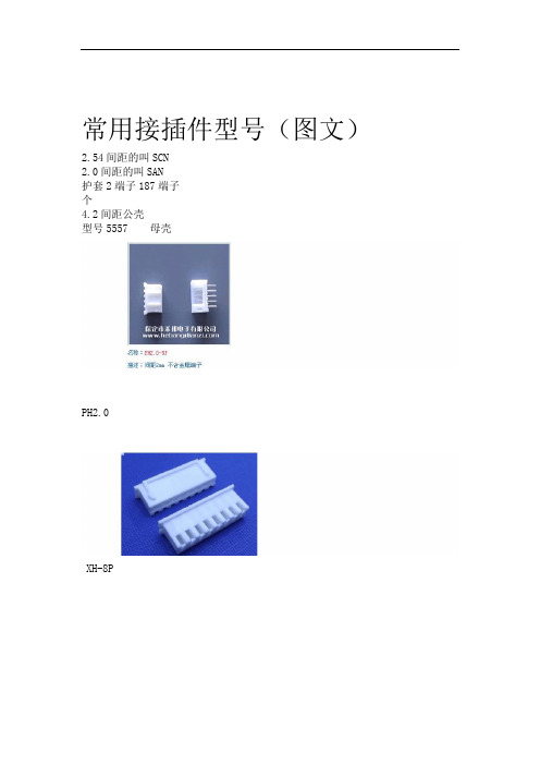
常用接插件型号(图文)2.54间距的叫SCN2.0间距的叫SAN护套2端子187端子个4.2间距公壳型号5557 母壳PH2.0XH-8PFD-14P 2.54间距CH3.96VH3.96ZH(1.5间距)EL特指4.5间距,SM指2.54间距DG1000-2P接插件LED显示屏/LED显示屏散件/P10半户外/16P排线压头 FC-16P接插件接插件 2.54间距 2*40P 双排针双排直针5.08-301-2P 接插件针座端子接插件 SM 脚距2.54 线1007公端子接插件 2.8插簧插片 2.8MM 铜XH-2.54-2P接插件1+1接插件VH3.96-2P接插件DC3-10P接插件接插件间距4.5MM 对插接插件接插件焊接式公头 DB25接插件 EL 2P 条形连接器CH3.96-5P接插件接插件 RS232串口 DB9母头 DB9孔全铜接插件标准6.3MM 插簧插片护套 0.5元/套冷压接线端子5.0MM 两位接插件2.54单排针,1*40P 排针接插件2.54MM接插件焊接式公头 DB37 蓝色PH2.0mm胶壳、针座、端子连接器、接插件系列XH2.54-3P接插件插件座间距2.54MMfc-16P接插件KF/DG1000-2p 接插件/接插座/接线端子脚间距10MM接插件杜邦线20CM1P-1P2P接插件(脚间距5.08mm)DC3-10P 接插件下载座JST对插接插件母壳 2P(10个MOG接插件 l连接器 2.0MM PH-2A针座(插座2.8端子型车用连接器接插件线缆连接器连接件对接 2线串口头接插件DR9针式板载式焊接式弯针插座(母头) RS232杜邦(间距2.0mm)双排胶壳,针座,端子连接器、接插件系列簧片+一套包括:头子+座子接插件接插件KF2510-6P 间距2.54适配器适配座转换座 PLCC44转DIP40 PLCC-44芯(贴片)接插件航空插头连接器 GX16-2T(2芯)接插件接插件测试插头插座十字插香蕉插 0.9元一对红色4.8接插件铜件两只脚焊板插片公端子接插件 6.3插簧插片 6.3MM 铜HT3.96-10P橙色,接插件DB25 公头/针二排25芯接插头接插件FC-8P 排线头接插件2.54间距一套6.3插簧接插件铜件直脚芯白色插座 2510-3接插件KF2510端子接插件端子 2.54MM冷压头簧片5557 连接件接插件 8孔连线器插座塑料连接件对插件DC3-20P接插件6.3-4 (6.3端子)型车用连接器接插件接线器 4线连接件XH2.54-2P接插件间距2.54MM 一套接插件XH2.54-10P 座子+线线长20CM接插件KF-4P 拔插式接线端子 KF2EDG 间距5.08MM 一套弯针SM-2P 对插锁紧接插件一套公壳+母壳+公簧片+母簧片USB A母连接头 A母插座 USB接插件XH2.54-5P接插件,连接器,针距2.54MM 端子座+插头+簧片一套PLCC 32贴片插座接插件连接器4.8直插/插簧/插片/对插件/单线连接器/单线接插件航空插头/GX16-2芯/一套/ 电缆连接器接插件【不锈钢】16型高品质航插航空插头航空插座接插件电连接器 8芯防水对接端子防水对插连接器汽车防水接插件密封防水对插端子1套大号皮套鳄鱼夹电子接插件接线夹连线夹香蕉插座香蕉插头香蕉接头接插件测试接头B101连接器2.8端子型/车用连接器/接插件/空中对接/摩托车 6PBNC插座铜镀金针BNC反接头 Q9头反接焊接方式摄像机视频接插件6.3多孔接插件电子连接件车用电器连接插头插座 3孔4+1接插件双皇冠接插件-MINI USB座贴片迷你 MINI-5P 铁LED显示屏/LED显示屏散件/P10半户外/16P排线压头 FC-16P接插件接插件杜邦线20CM8P-8P香蕉插头质量好连接头测试头接插件 DIY电子实验制作配件连接器接插件SCSI68PIN双母头连接线接插件6.3带护套接插件铜件连接器TJC3 2.54 XH-2AW(2位弯脚插座/90度)批发 P48-26芯大电流航空插头接头电缆接插件SM2.5-3P公母对接胶壳,端子,条形连接器,接插件,黑色,1套弯针XH2.54-2P接插件间距2.54MM 一套:插头+弯插座+端子 20MOG电源插头接插件电源座。
AMP产品规范 108-1699 (AMP - DUAC 排针)

AMP – DUAC*排针1.范围1.1.内容此规范包括AMP-DUAC*排针的性能, 测试及质量要求. 此2-24 pin垂直排针的设计是为了供应电源及用插座连接器上端子的母头半插入在有已极化的塑胶排针上 1.14mm 方形柱杆上, 以防止排针半插入处有不正确的插入.1.2.质量在生产线上测试时, 应采用AMP109系列规范中规定的程序. 所有的检测应在使用相应的检测计划及产品图纸下进行.1.3.质量测试结果对受检测的生产线顺利的质量测试已于98年1月完成. 测试文件号为CTL8221-000-004A. 文件已归档并保存在ARL中.2.适用文件下列文件是目前规定的此规范的一部分. 除非另有规定, 适用文件的最新版本. 当此规范的要求与产品图纸相冲突时, 以产品图纸为准. 当此规范的要求与参考文件相冲突时, 以此规范为准.2.1.AMP文件A.109-1: 测试规范总要求.B.109系列: 表1中含有的测试规范.C.公司公告401-76: 与AMP测试规范及军事或商业文件相互参考.D.114-6067 : 适用规范(仅缆线卷适用)E.501-434: 质量测试报告3.要求3.1.设计及构造产品设计及构造及物理尺寸应符合适用的产品图纸.3.2.材料A.端子: 镍打底镀黄铜, 锡铅或双倍的金/锡铅.B.塑胶主体: 热塑性塑胶, UL94V-0 或UL94V-2.3.3.额定值A.电压: 600vac.B.电流: 参照表3可取得适用的电流量..C.温度: -55度至105度3.4.性能及测试描述产品设计必须符合表1中规定的电气性能, 机械性能及环境性能要求. 除非另有规定, 所有的测试都必须在AMP规范109-1中规定的周围环境条件下进行.3.5.测试要求及程序概述及再测试的要求.表13.6.产品质量及测试及再测试的顺序.(b): 数字是指测试进行的顺序.(c ): 不要测量不连续性. 根据AMP规范109-151在18度的水平下通电以100%加载.(d): 预先将样品转10圈.表24.质量保証条款4.1.质量测试A.选样样品应按照适用的指示来准备, 且应从现有的样品中随机取样. 每个测试群组由5个以上的样品组成. 除非测试程序另有规定, 测试群组1和2的样品是AMP-DUAC 排针与相应的AMP-DUAC插槽连接器(如, 106527系列插座塑胶及106528或106529系列端子)配对的样品. 测试群组1应在缆线尺寸最大时结束. 测试群组1和2的样品应安装在料号为60-469228-1的印刷电路板上. 测试群组3的样品不须配对也不须安装在电路板上.B.测试顺序质量检验应由表2中规定的测试样品来核实.4.2.质量再检验测试如果产品的或生产过程的变化严重影响了产品形状, 产品的安装或功能, 应再进行质量测试以确保产品质量, 测试应按开发/产品, 质量及可靠的工程决定且由全部或部分的原有测试顺序组成.4.3.合格产品符合表1中的要求即为产品合格. 由于测试设备, 装置或操作员的失误导致失败不能算是产品质量不合格. 若发现产品不合格, 应采取正确措施再次送样进行产品质量再测试. 再次送样进行测试时应确保所采取的措施是正确的.4.4.质量一致检验适用的AMP质量检验规划会规定应用的产品合格的质量水平. 尺寸及功能要求应与适用的产品图纸及本规范一致.注意: 为决定连接器导通率及缆线量规显示的可接受电流承载量, 可用上表中的乘法因素乘上基准电即为在图3A中显示的最大环境操作温度下单个电路上的电流承载量.。
常用国产型号对应AMP端子选型表
59
2系列
60
2系列
61
2系列
62
2.2系列
DJ7051-1.5-21 DJ7061-1.5-21 DJ7061-1.5-11 DJ623-E1.5A
DJ611-1.5×0.8A DJ7022-1.8-11 DJ7042-1.8-21 DJ7163-1.8-21 DJ7201-1.8-21 DJ7063-1.8-21 DJ7033-1.8-21 DJY7201-1.8-11
DJ7044-1.8-21 DJ7023-1.8-21
DJ614-G1.8A DJ624C-1.8A
DJ624C-1.8B DJ624B-1.8B DJ624-G1.8A DJ624-1.8A DJ7026-2-21 DJ7026-2-20 DJ7026-2-11 DJ7026-2-10 DJ7166-2-20 DJ7166-2-21 DJ3021-2-21 DJ3021-2-21-1 DJ7106-2-21 DJ623-2×0.6A DJ613-2×0.6A DJ7063-2.2-20
316371 316372 316370-6 173 716-1 282079-1 282103-1 282080-1 282104-1 282087-1 282105-1 282088-1 282106-1 444515-1 282107-1
31
1.5系列
32
1.5系列
33
1.5系列
34
1.5系列
1-967642-1 928999-1 963715-1 962885-1 965906-1
1-967616-1 C-1318917 1318389-1 1565380-1 1-967644-1 4-1437287-6 1123343-1 174966-2 179054-6锁件 179054-6 174047-2
国产接插件护套和安普的对应匹配表
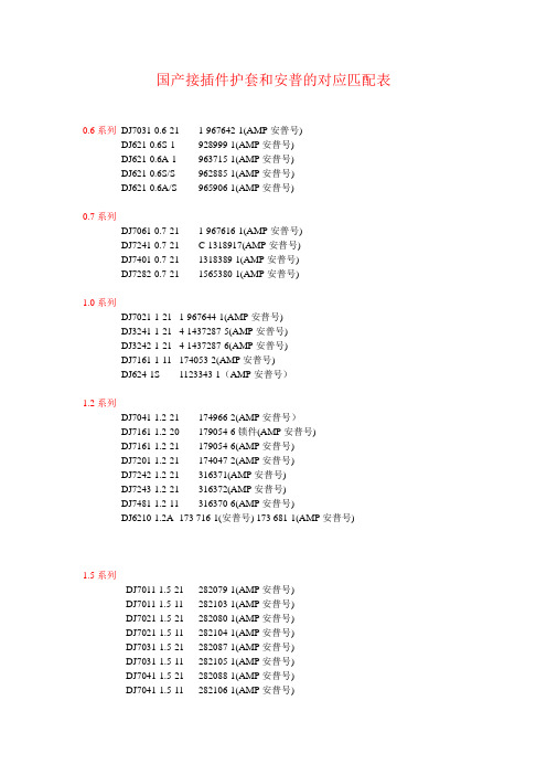
国产接插件护套和安普的对应匹配表0.6系列DJ7031-0.6-21 1-967642-1(AMP安普号)DJ621-0.6S-1 928999-1(AMP安普号)DJ621-0.6A-1 963715-1(AMP安普号)DJ621-0.6S/S 962885-1(AMP安普号)DJ621-0.6A/S 965906-1(AMP安普号)0.7系列DJ7061-0.7-21 1-967616-1(AMP安普号)DJ7241-0.7-21 C-1318917(AMP安普号)DJ7401-0.7-21 1318389-1(AMP安普号)DJ7282-0.7-21 1565380-1(AMP安普号)1.0系列DJ7021-1-21 1-967644-1(AMP安普号)DJ3241-1-21 4-1437287-5(AMP安普号)DJ3242-1-21 4-1437287-6(AMP安普号)DJ7161-1-11 174053-2(AMP安普号)DJ624-1S 1123343-1(AMP安普号)1.2系列DJ7041-1.2-21 174966-2(AMP安普号)DJ7161-1.2-20 179054-6锁件(AMP安普号)DJ7161-1.2-21 179054-6(AMP安普号)DJ7201-1.2-21 174047-2(AMP安普号)DJ7242-1.2-21 316371(AMP安普号)DJ7243-1.2-21 316372(AMP安普号)DJ7481-1.2-11 316370-6(AMP安普号)DJ6210-1.2A 173 716-1(安普号) 173 681-1(AMP安普号)1.5系列DJ7011-1.5-21 282079-1(AMP安普号)DJ7011-1.5-11 282103-1(AMP安普号)DJ7021-1.5-21 282080-1(AMP安普号)DJ7021-1.5-11 282104-1(AMP安普号)DJ7031-1.5-21 282087-1(AMP安普号)DJ7031-1.5-11 282105-1(AMP安普号)DJ7041-1.5-21 282088-1(AMP安普号)DJ7041-1.5-11 282106-1(AMP安普号)DJ7045-1.5-21 444515-1(AMP安普号) 1717892-1(AMP安普号)DJ7051-1.5-21 282089-1(AMP安普号)DJ7051-1.5-11 282107-1(AMP安普号)DJ7061-1.5-21 282090-1(AMP安普号)DJ7061-1.5-11 282108-1(AMP安普号)DJ623-E1.5A 962 876-1(AMP安普号)DJ611-1.5×0.8A 282 109-1(AMP安普号)1.8系列DJ7022-1.8-11 348794-3(AMP安普号)DJ7042-1.8-21 174922-1(AMP安普号) 368501-1(AMP安普号)DJ7044-1.8-21 444046-1(AMP安普号)DJ7163-1.8-21 179631-1(AMP安普号)DJ7201-1.8-11 174936-1(AMP安普号)DJ7201-1.8-21 174952-1(AMP安普号) 368511-1(AMP安普号)DJ7023-1.8-21 348793-3(AMP安普号)DJ7063-1.8-21 174923-1(AMP安普号)DJ7033-1.8-21 174921-1(AMP安普号)DJY7201-1.8-11 175785-1(AMP)DJ614-G1.8A 173 645-1(AMP安普号)DJ624C-1.8A 282438-1(AMP安普号)DJ624C-1.8B 282 466-1(AMP安普号)DJ624B-1.8B 776 001-1(AMP安普号)DJ624-G1.8A 173 631-1(AMP安普号)DJ624-1.8A 282403-1(AMP安普号)2系列DJ7026-2-21 174352-2(AMP安普号)DJ7026-2-20 174353-7(AMP安普号)DJ7026-2-11 174354-2(AMP安普号)DJ7026-2-10 174355-7(AMP安普号)DJ7166-2-20 368049-1(AMP安普号)DJ7166-2-21 368047-1(AMP安普号)DJ3021-2-21 353377-7(AMP安普号)DJ3021-2-21-1 353378-2(AMP安普号)DJ7106-2-21 174655-2(AMP安普号)DJ623-2×0.6A 171 662-1(AMP安普号) 184030-3(AMP安普号)DJ613-2×0.6A 171 661-1(AMP安普号) 171631-1(AMP安普号)2.2系列DJ7063-2.2-20 936269-1(AMP安普号)DJ7063-2.2-21 936268-1(AMP安普号)DJ7163-2.2-10/20 936203-1(AMP安普号)DJ7163-2.2-11 936211-1(AMP安普号)DJ7163-2.2-21 936201-1(AMP安普号)DJ7163-2.2-11装配体936211-1(AMP安普号)DJ627-2.2X0.6A 368084-1(AMP安普号)DJ627-2.2X0.6S 368085-1(AMP安普号)2.8系列DJ613-2.8×0.8A 962880-2(AMP安普号)DJ616-2.8×0.8A 962883-2(AMP安普号)DJ616-2.8×0.8B 962884-2(AMP安普号)LC968H.1.1-4 962841-1(AMP安普号)DJ614-2.8*0.8A 142754-1(AMP安普号)3系列DJ7021-3-21 610207-5(AMP安普号)DJ7112-3-21 0-144521-4(AMP安普号)DJ7092-3-21 0-144520-2(AMP安普号)DJ7052-3-21 0-144518-1(AMP安普号)DJ7251-3-11 827535-1(AMP安普号)DJ6232-E3A 925590-1(AMP安普号)3.5系列DJ7023-3.5-21 282189-1(AMP安普号)DJ7024-3.5-11 357 972 762 929741-5(AMP安普号)DJ7031-3.5-21 443 906 233 828840-1(AMP安普号)DJ7031A-3.5-21 282246-1(AMP安普号)DJ7033-3.5-21 282191-1(AMP安普号)DJ7041K-3.5-21 144998-5(AMP安普号)DJ7043-3.5-21 282192-1(AMP安普号)DJ7551-3.5-21外壳282092-1(AMP安普号) 85214-1(AMP安普号) DJ7553-3.5-21外壳963534-1(AMP安普号) 1-85121-1(AMP安普号) DJ7082A-3.5-21 962189-1(AMP安普号)DJ623B-E3.5A-1 964284-2(AMP安普号)DJ623B-E3.5B-1 965999-2(AMP安普号)DJ611-3.5A 928 781-1(AMP安普号)DJ623-E3.5A/S 185 026-1(AMP安普号)DJ623-E3.5B/S 185 027-1(AMP安普号)DJ623-E3.5A/S镀金2-964 286-1(AMP安普号)DJ623C-E3.5S 0-0964280-2(AMP安普号)DJ623C-E3.5S/S 0-0964282-2(AMP安普号)DJ623C-E3.5C 0-0965999-2(AMP安普号)DJ623C-E3.5C/S 0-0964273-2(AMP安普号)4.0系列DJ7021-4-25 142680-4(AMP安普号)4.8系列DJ622-D4.8B 54-01 60430-7(AMP安普号)DJ615-4.8×0.8B 962904-2(AMP安普号)6系列DJ7023-6-21 MG610263(KET)DJ7012-6-11 174195-1(AMP安普号)DJ7012-6-21 172128-2(AMP安普号)DJ7022-6-11 172129-2(AMP安普号)DJ7022-6-21 172130-2(AMP安普号)DJ626-D6B 170 032-1(AMP安普号)6.3系列DJ7019-6.3-21 180984-1(AMP安普号)DJ7022-6.3-21 174198-1(AMP安普号)DJ7068-6.3-21 174204-1(AMP安普号)DJ624-D6.3B 927854-2(AMP安普号)DJ624-D6.3C 154 717-1(AMP安普号)DJ624- D6.3A 0-0927852-2(AMP安普号)DJ6218-E6.3A 964324-1(AMP安普号)DJ6218-E6.3B 969042-1(AMP安普号)DJ6218-E6.3C 964328-1(AMP安普号)DJ628-6.3B 963887-2(AMP安普号)DJ6210-6.3B 170454-1(AMP安普号)DJ6211-6.3B 171632-1(AMP安普号)DJ626-6.3B 170032-5(AMP安普号)DJ6232-E6.3A 927847-2(AMP安普号)DJ612-6.3B 0-0928962-3(AMP安普号)DJ627-D6.3(0.5~1.0平方线) 160861-1(AMP安普号) DJ628A-6.3B 963887-2(AMP安普号)DJ627-D6.3B 2-0180464-1(AMP安普号)DJ622-D6.3B 140760-4(AMP安普号)DJ621-A6.3A 160870-3(AMP安普号)DJ621-A6.3B 160824-6(AMP安普号)8系列DJ7022A-8-11 1544459-2(AMP安普号)DJ7022C-8-11 1544459-1(AMP安普号)DJ7022B-8-11 1544459-3(AMP安普号)9.5系列DJ221-2S 353376-3(AMP安普号)DJ221-1S 1437284-9(AMP安普号)复合系列DJ7811-1.2/3.5-21-1 368290-1(AMP安普号)DJ7811-1.2/3.5-21-3 368333-1(AMP安普号)DJ7811-1.2/3.5-21-4 368293-1(AMP安普号)DJ7811-1.2/3.5-21-5 368294-1(AMP安普号) DJ7811-1.2/3.5-21-6 368297-1(AMP安普号) DJ7161-1.8/2.8-11 967376-2(AMP安普号) DJ7161-2.3/6.3-21 368454-1(AMP安普号) DJ7181-2.3/6.3-21 368497-1(AMP安普号) DJ7201-2.3/6.3-21 368457-1(AMP安普号) 线卡系列JZ-XK-10 345484-1(AMP安普号) 密封堵系列MFD003-2 828905-1(AMP安普号)MFD006-4 828904-1(AMP安普号)MFD005-4 963293-1(AMP安普号)MFD001-8 963530-1(AMP安普号)杂件系列1393449-1 1-1393449-1(AMP安普号)JB214 284352-1(AMP)。
AMP-NETCONNECT-光纤及六类综合布线系统解决方案
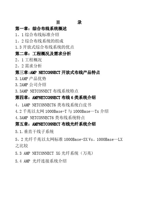
目录第一章:综合布线系统概述1。
1综合布线标准介绍1。
2综合布线系统的组成1.3开放式综合布线系统的优点第二章:工程概况及需求分析2。
1工程概况2。
2需求分析第三章:AMP NETCONNECT开放式布线产品特点3.1AMP产品优势3.2AMP公司介绍3.3AMP NETCONNECT布线系统特点第四章:AMPNETCONNECT布线6类系统介绍4。
1AMP NETCONNECT6类布线系统白皮书4.2千兆以太网1000Base-T与1000Base—Tx介绍4.3AMP NETCONNECT6类布线系统特点第五章:AMPNETCONNECT布线光纤系统介绍5.1.垂直干线子系统5。
2光纤千兆以太网标准1000Base-SX Vs。
1000Base—LX 之比较5.3 AMP NETCONNECT XG光纤系统(万兆)5.4 AMP 光纤连接系统介绍第六章:综合布线系统设计方案6.1设计原则6。
2总体结构论述6。
3各结构化子系统详述及方案说明设备定型6.4综合布线及设备报价第七章:管线设计方案7.1水平子系统管线设计7.2设备电源管线方式7。
3设备间弱电接地方式第八章:综合布线系统测试8。
1测试依据8.2测试设备8。
3测试参数第九章:系统维护与技术支持第一章:综合布线系统概述1.1综合营企业布线标准介绍综合布线系统最初产生于八十年代初期的美国,是随着通信技术和计算机连网技术的发展而发展起来的,八十年代末期综合布线技术在设计、产品、标准、测试等方面取得了突飞猛进的发展;欧美许多发达国家先后制定标准对其进行规范,其中被许多国家广泛采用的有美国电子工业协会/电信工业协会制定的TIA/EIA 568B标准和国际标准化组织制定IS0/IEC11801标准;这两个标准的制定对促进综合布线技术的普及和计算机网络技术的发展奠定了基础;我国对综合布线技术的推广应用也非常重视,并于1995年由中国工程建设标准化协会制定了国内第一部结合国情的综合布线标准:《建筑与建筑群综合布线系统工程设计规范》(CECS72:95);1997年该标准得到了进一步完善,其新标准《建筑与建筑群综合布线系统工程设计规范》(CECS72:97)对抗干扰、防噪音、防火、防毒等关键技术方面作出了新的规定;同时《建筑与建筑群综合布线系统工程施工及验收规范》(89:97)也相继出台,这对规范我国综合布线产业无疑将产生积极的影响。
信捷伺服常见问题分析解答(只针对DS2系列)
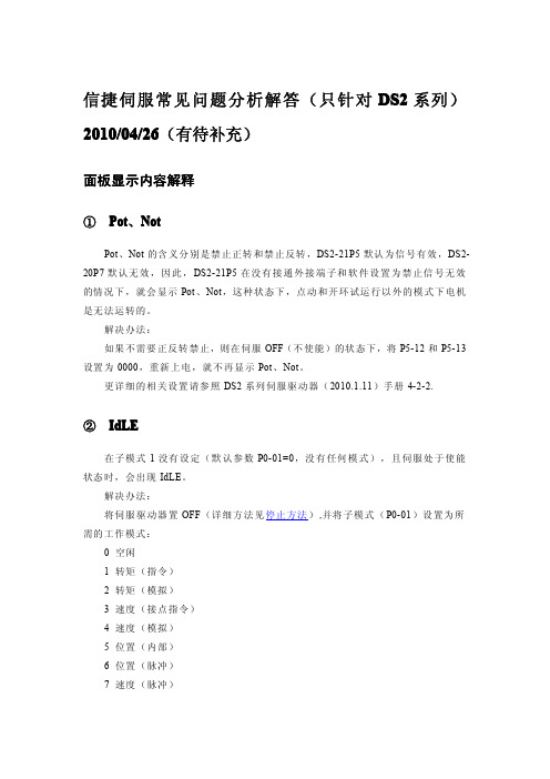
信捷伺服常见问题分析解答(只针对DS2系列)2010/04/26(有待补充)面板显示内容解释①Pot、NotPot、Not的含义分别是禁止正转和禁止反转,DS2-21P5默认为信号有效,DS2-20P7默认无效,因此,DS2-21P5在没有接通外接端子和软件设置为禁止信号无效的情况下,就会显示Pot、Not,这种状态下,点动和开环试运行以外的模式下电机是无法运转的。
解决办法:如果不需要正反转禁止,则在伺服OFF(不使能)的状态下,将P5-12和P5-13设置为0000,重新上电,就不再显示Pot、Not。
更详细的相关设置请参照DS2系列伺服驱动器(2010.1.11)手册4-2-2.②IdLE在子模式1没有设定(默认参数P0-01=0,没有任何模式),且伺服处于使能状态时,会出现IdLE。
解决办法:将伺服驱动器置OFF(详细方法见停止方法),并将子模式(P0-01)设置为所需的工作模式:0空闲1转矩(指令)2转矩(模拟)3速度(接点指令)4速度(模拟)5位置(内部)6位置(脉冲)7速度(脉冲)③bb、runbb表示伺服驱动器处于停止(未使能)状态,run表示伺服驱动器处于运行(使能)状态。
④EEEEx表示显示面板与数字处理器通讯不畅。
伺服使能与停止①伺服使能a,默认情况下(P5-10=0001),给伺服驱动器的第一个信号输入端一个导通信号,具体的接线方式为,电源的24V接到伺服驱动器的+24V,电源的0V通过开关接到SI1.b,如果需要上电使能,则将P5-10设置为0010,重新上电后有效。
②伺服停止a,将外部使能信号断开,并将外接IO端子拆除;b,将P5-10设置为0001,然后重新上电;c,以上两个步骤均无效的情况下,查看U-22,若第5个数码管的第一横亮,则说明CPU板的输入端子出现短路(需要返修)。
参数无法修改部分参数在伺服处于使能状态时,是不能进行更改的,恢复出厂也无效,如果需要修改,就要先将伺服驱动器置OFF。
