TestTools使用说明书
GM650TestTool使用说明
GM650TestTool V1.0 使用说明 V1.0深圳市有方科技有限公司 有无线,方精彩Let's enjoy the wireless life!GM650TestTool v1.0 使用说明 V1.0版权声明Copyright © 2008 Neoway Technology 深圳市有方科技有限公司保留所有权利。
是深圳市有方科技有限公司所有商标。
本手册中出现的其他商标,由商标所有者所有。
说明本指南的使用对象为系统工程师,开发工程师及测试工程师。
由于产品版本升级或其它原因,本手册内容会在不预先通知的情况下进行必要的更新。
除非另有约定,本手册中的所有陈述、信息和建议不构成任何明示或暗示的担保。
深圳市有方科技有限公司为客户提供全方位的技术支持,任何垂询请直接联系您的客户经理 或发送邮件至以下邮箱: Sales@ Support@ 公司网址:深圳市有方科技有限公司版权所有 第 2 页,共 7 页 GM650TestTool v1.0 使用说明 V1.0目1 2 3录 概述 ....................................................................5 功能使用说明 ............................................................5 常见问题及解决办法 ......................................................6 深圳市有方科技有限公司版权所有 第 3 页,共 7 页 GM650TestTool v1.0 使用说明 V1.0修版本号 V1.0 更改内容 初始版本 订记录生效年月 2012‐07 深圳市有方科技有限公司版权所有 第 4 页,共 7 页 GM650TestTool v1.0 使用说明 V1.01 概述 GM650TestTool 是专门为 GM650 模块开发的一款测试软件工具, 用于测试 GM650 模块 GPS 模组的性能。
TestSoftV1.1静载锚固试验机测控软件说明书

目录第1章安装和运行 (3)1.1 运行环境 (3)1.2 安装 (3)1.3 卸载 (4)第2章简介 (5)2.1 功能简介 (5)2.2 界面简介 (5)2.2.1 系统菜单 (6)2.2.2 工具栏 (15)2.2.3 示值显示栏 (16)2.2.4 试验参数 (17)2.2.5 试验过程 (18)2.2.6 多图曲线 (18)2.2.7 试验信息 (19)2.2.8 试验步骤 (20)2.2.9 结果处理 (21)2.2.10 速度显示栏 (22)2.2.11 状态栏 (23)第3章如何完成第一个试验 (24)3.1 启动软件 (24)3.2 新建试验 (24)3.3 填写试验前参数 (24)3.4 装夹试样 (24)3.5 运行试验 (24)3.6 观察试验 (25)3.7 结束试验 (25)3.8 卸下试样 (25)3.9 查询 (25)3.10 报告打印 (25)3.11 退出程序 (25)第4章试验 (26)4.1 试验前设置 (26)4.2 静载锚固试验 (26)4.2.1 打开试验软件,进入程序 (26)4.2.2 新建试验 (26)4.2.3 输入试验参数 (26)4.2.4 清零 (26)4.2.5 装夹试样 (26)4.2.6 运行 (27)4.2.7 试验结果 (27)4.2.8 试验后解释 (27)第5章分析试验 (28)5.1 查找试验记录 (28)5.2 观察试验分析曲线图 (29)5.2.1 加入移出曲线 (29)5.2.2 更改曲线坐标轴 (29)5.2.3 曲线缩放平移 (30)5.3 自定义报告 (30)5.4 试验前参数 (30)5.5 试验后参数 (30)5.6 参数点 (30)第6章校准及检定 (33)6.1 检定界面介绍 (33)6.1.1 检定点设定 (33)6.1.2 自定义检定方式 (34)6.1.3 显示检定结果 (34)6.1.4 更改标定参数 (35)6.2 力值检定 (37)6.2.1 检定步骤: (37)6.2.2 修正步骤: (38)第1章安装和运行1.1运行环境计算机硬件配置:打印机配置:支持各种打印机;计算机操作系统配置:中文,英文windows 98/2000/XP操作系统1.2安装1.双击打开光盘中setup.exe文件,程序就会自动开始安装;图1:软件初始界面2.在接下来的出现的窗口中,点击“下一步”,出现安装路径选择窗口;图2:安装确认界面3.在安装路径选择窗口设置路径,点击“下一步”。
西安诺瓦星云科技股份有限公司诺瓦异步交通程序测试工具用户手册说明书

司公限有份股技科云星瓦诺安西更新记录司科云星瓦诺安西 i目录更新记录 ............................................................................................................................... i 目录......................................................................................................................................i i 1 简介 (1)2 环境搭建 (2)2.1 准备硬件 (2)2.2 准备软件 ................................................................................................................................................ 2 2.3 连接控制卡 .. (2)2.4 获取IP 地址 (2)3 诺瓦交通标准协议测试 (4)3.1 设置连接参数 ......................................................................................................................................... 4 3.2 连接控制卡 ............................................................................................................................................ 6 3.2.1 控制卡为服务端模式 ............................................................................................................................ 6 3.2.2 控制卡为客户端模式 ............................................................................................................................ 7 3.3 测试通信协议 ......................................................................................................................................... 7 3.3.1 身份验证和通信安全校验 ..................................................................................................................... 7 3.3.2 屏体/电源控制相关 .............................................................................................................................. 7 3.3.3 亮度相关 ............................................................................................................................................. 8 3.3.4 告警相关 ............................................................................................................................................. 8 3.3.5 文件/播放相关 ..................................................................................................................................... 8 3.3.6 点检参数 .. (10)3.3.7 时间操作 ............................................................................................................................................10 3.3.8 其他操作 .. (10)4 三思交通标准协议测试 (12)4.1 设置连接参数 ........................................................................................................................................12 4.2 连接控制卡 . (14)4.3 测试通信协议 ........................................................................................................................................15 5 海信交通标准协议测试 (17)5.1 设置连接参数 ........................................................................................................................................17 5.2 连接控制卡 . (18)西安诺瓦星云科技股份有限公司5.3 测试通信协议 ........................................................................................................................................19 5.3.1 Base64编码图片预览 .........................................................................................................................19 5.3.2 终端设置 ............................................................................................................................................20 5.3.3 发送报文 .. (21)6 Q&A (22)6.1 如何通过其他方式连接控制卡 ................................................................................................................22 6.2 如何重启控制卡 ....................................................................................................................................23 6.3 如何切换界面语言 .................................................................................................................................24 6.4 如何生成RDS 配置文件 (25)西安诺瓦星云科技股份有限公司用户手册1 简介1简介JT100为诺瓦科技针对交通领域的LED 全彩显示屏推出的多媒体播放器。
测试设备说明手册(TESTO)说明书
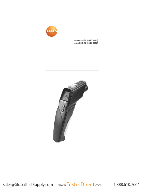
testo 830-T1 (0560 8311) testo 830-T2 (0560 8312)91. General Information Please read this document through carefully and familiarise yourself with the operation of the product before putting it to use.Keep this documentation to hand so that you can refer to it when necessary.2. Product Description3. Safety InformationContact measurement: Do not measure on or near live parts. Infrared measurement: Please adhere to the required safe distance when measuring on live parts.Operate the instrument properly and according to its intended purpose and within the parameters specified. Do not use force.Do not expose to electromagnetic radiation (e.g. microwaves,induction heating systems), static charge, heat or extreme fluctuations in temperature.Do not store together with solvents (e.g. acetone).Open the instrument only when this is expressly described in the documentation for maintenance purposes.Laser radiation! Do not look into laser beam. e n Accessories Name Item no.Water-tight immersion/penetration probe, -60 to +400°C/-76 to +752°F 0602 1293Quick-reaction surface probe, -60 to +300°C/-76 to +572°F 0602 0393Robust air probe, -60 to +400°C/-76 to +752°F 0602 1793Leather protection sleeve 0516 8302Emissivity adhesive tape ε=0.950554 0051Infrared sensor,laser Battery compartment DisplayOn/Off switch Contact measurement Measurement button:infrared measurement Infrared measurementProbe socket (testo 830-T2 only)10Ensure correct disposal:Dispose of defective rechargeable batteries and spentbatteries at the collection points provided.Send the instrument directly to us at the end of its life cycle.We will ensure that it is disposed of in an environmentallyfriendly manner.4. Intended Usetesto 830 is a compact infrared thermometer for the non-contact measurement of surface temperatures. Using testo830-T2, it is possible to carry out additional contact measurements byattaching probes.5. Technical DataFeature testo 830-T1testo 830-T2Parameter°C/°FInfrared measurement range-30 to +400°C/ -22 to +752°FInfrared resolution0.1°C/0.1°FInfrared accuracy±1.5°C/ 2.7°F or 1.5% of reading (+0.1 to +400°C/ +32 to +752°F)1;(at 23°C) +/- 1 digit±2°C/ 3.6°F or 2% of reading (-30 to 0°C/ -22 to +31.9°F)1Emissivity0.1 to 1.0 adjustableInfrared measurement rate0.5sTemp. sensor -Thermocouple Type K (attachable) Measurement range of temp sensor--50 to +500°C/ -58 to +932°F Resolution of temp. sensor-0.1°C/ 0.1°FAccuracy of temp. sensor-±0.5°C/0.9°F+0.5% of reading (±1 digit)at rated temperature 22°C/ 72°F Measuring rate of temp. sensor- 1.75sOptics (90% value)10:1212:12Laser type 1 x laser 2 x laserOperating temperature-20 to +50°C/ -4 to +122°FTransport /S torage temperature-40 to +70°C/ -40 to +158°FPower supply9V block batteryBattery life 20 h 15 hHousing ABSDimensions (LxHxB)190 x 75 x 38mm/ 7.5 x 3.0 x 1.5inCE guideline2004/108/EECWarranty 2 yearsLaserLaser type 1 x laser 2 x laserPower< 1 mWWavelength645 to 660 nmClass2Standard DIN NE 60825-1:2001-111the larger value applies2+ Opening diameter of the sensor (16mm/ 0.6in)6. Initial OperationInsert battery: See 9.1Changing the battery.117. Operation7.1 Connecting probe (testo 830-T2 only)Connect temperature probe to probe socket. Observe +/-!7.2 Switching on/offSwitch on instrument: Press measurement button.-lights up).The display light remains for 10 seconds every time a button is activated.pressed until display darkens.The device switches off automatically after 1 min (IR measure -ment view) or 10 mins (contact measurement view, only testo830-T2) without the button being pressed.7.3 Measuring/ measurement, this is done when the device is switched off orwhen you switch to the IR measurement view.-The instrument is switched on.Infrared measurement1Start measurement: Hold down measurement button.2Locate object to be measured using laser point.testo830-T1: laser marks the centre point of the measurement spot.testo830-T2: Laser marks the upper and lower end of themeasurement spot.-The current reading is shown (2 measurements per second)3End measurement: Release button.-HOLD lights up. The last measured value and min./max. value are saved until the next measurement.Restart measurement: Press measurement button.Contact measurement (testo 830-T2 only)-Temperature probe was connected before the measuring instrument was switched on.1-The instrument changes to the contact measurement mode (lights up). The current reading is shown.en122End the measurement: Press .-HOLD lights up. The last measured value and min./max. value are saved until the next measurement.Switch between min., max. and recorded value: Press .Restart measurement: Press .Back to infrared measurement view: Press measurementbutton.Setting the emissivity-Instrument is in the infrared measurement mode.If no button is pressed for 3 s in the emissivity mode, theinstrument switches to the infrared measurement mode.1Press for 3 s.2Set emissivity: Press or-The instrument switches to the infrared measurement mode.8. Settings-Instrument is switched off.If no button is activated in the setting mode for 3 s, theinstrument changes to the next mode.1Press for 3 s.-The device switches to settings mode.2Set lower alarm value (ALARM): Press or . Hold the button down to go forward quickly.3Set upper alarm value (ALARM): Press or . Hold the button down to go forward quickly.4Set alarm function on/oFF: Press or .5Select parameter (°C/ °F) : Press or .-The device returns to IR measurement view.The alarm function is only available for IR measurement. If theset alarm values are exceeded/not reached, a visual andacoustic alarm is output.9. Service and Maintenance9.1 Changing the batteryInstrument must be switched off!1Open battery compartment:Open up cover.2Remove used battery and insert newone. Observe +/-. The minus should bevisible once the battery is inserted.3Close battery compartment: Closecover.139.2 Clean instrument Do not use abrasive cleaning agents or solutions.Clean the housing with a damp cloth (soap water).Carefully clean the lens with water or cotton buds dipped in water or medical alcohol. 10. Questions and AnswersQueryPossible causes Possible solutionInfrared measurement mode: -Readings outside -- - -lights up.measurement range.Contact measurement mode: -Readings outside -If we have not answered your question, please contact your local distributor or Testo´s Customer Service.11. Information on infrared measurement 11.1 Measurement methodInfrared measurement is an optical measurementKeep lens clean.Do not measure with clouded lens.Keep measurement field (area between instrument and object being measured) free of interferences: no dust and dirtparticles, no moisture (rain, steam) or gases.Infrared measurement is a surface measurementIf there is dirt, dust, frost etc. on the surface, only the top layer will be measured, i.e. the dirt.In the case of shrinkwrapped foodstuffs, do not measure in air pockets.If values are critical, always subsequently measure using a contact thermometer. Particularly in the food sector, the core temperature should be measured with a penetration/immersion thermometer.Adaptation timeIf the ambient temperature changes (change of location, e.g.inside/outside measurement) the instrument needs an adaptation time of 15 minutes for infrared measurement.e n1411.2 EmissivityMaterials have different emissivities, i.e. they emit different levels of electromagnetic radiation. The emissivity of testo 830 is set in the factory to 0.95. This is the ideal value for measuring non-metals (paper, ceramics, plaster, wood, paints and varnishes),plastics and foodBright metals and metal oxides are only suited to a limited extent to infrared measurement on account of their low or nonuniform emissivity.Apply emissivity enhancing layers such as varnish or emission adhesive tape (Item no. 05540051) to the object being measured. If this is not possible, measure with the contact thermometer.Emissivity table of the most important materials(typical values)A specific spot is determined depending on the distance from the measuring instrument to the object being measured. Measurement optics (Ratio Distance : Measurement spot)500 mm1000 mm2000 mm5000 mmØ 516 mmØ 216 mmØ 116 mmØ 66 mmØ 16 mm testo 830-T1laser1512. Information on contactmeasurementObserve minimum penetration depth in immersion/penetration probes: 10 x probe diameterAvoid applications in corrosive acids or bases.Do not use spring-loaded surface probes on sharp edges.e n 500 mm 1000 mm2000 mm 5000 mm Ø 433 mm Ø 183 mmØ 100 mmØ 58 mm Ø 16 mm testo 830-T2laserlaser。
TestXpertII中文操作说明书

Zwick 软件操作说明一启动testXpertII程序二设置机器参数三设置测试参数——向导四 ZWICK万能材料试验机操作步骤(拉伸测试)五安全措施说明六修整七维护保养说明一、启动testXpertII程序1、打开计算机及控制箱上的电源2、双击图标3、单击“打开”将会出现如下图所示,显示所有程序4、双击所选程序5、单击“确定”,进入测试界面打开控制面板上的电源on二、设置机器参数1、单击“试验机”图标,将出现“标准仪器设置”框。
如图所示:上软限位(在程序控制下,横梁所能到达的最高位置,可根据实际情况设定)下软限位(在程序控制下,横梁所能到达的最低位置,可根据实际情况设定)当前工具间距/当前夹具间距(每次更换夹具时,都要将实测的夹具间距离值输入这里)载荷上限(设置载荷的上限位保护,一般为满负荷的120%)载荷下限(设置载荷的下限位保护,一般为满负荷的-120%)标准引伸计(当采用横梁做为位移测量时,选择横梁WN:******,当采用引伸计传感器做为位移测量时,请选择长量程引伸计WN:******)2、点击“扩展”如图所示:2.5N1S WN:170862 (机器编号)和试验机(机器)相连横梁 WN :170862(横梁编号)和横梁相连长量程引伸计(引伸计的名称)和标准引伸计相连当不使用长量程引伸计时,请将标准引伸计和横梁相连,如下图所示力传感器0.5KN(传感器的负荷)和标准传感器相连。
2、在“测试环境”中取一个名称,保存机器设置结果,不同的设置请保存为不同的“测试环境”名。
3、点击“确定”退出。
三、设置测试参数——Wizard(向导)用户所有的测试参数都在“向导”里设定和执行1、进入向导,单击“预测试”,进入如下文本框可根据需要设定文本框中的内容应注意:预载力一般为0.1---2N,预载测试速度一般为10mm/min,可根据实际情况设定。
在参数前口里打x 的为选择所需的测试参数,参数前口里没有打 x的未选。
mytest使用手册

mytest使用手册MyTest是一款强大的测试管理工具,旨在帮助开发人员和测试人员更好地组织、管理和执行测试用例。
以下是MyTest的使用手册,以便您更好地了解如何使用该工具。
一、概述MyTest是一个易于使用的测试管理工具,提供了全面的测试用例管理功能,包括测试用例的创建、编辑、运行、跟踪和报告等。
通过MyTest,您可以将测试用例与需求、缺陷和其他相关元素关联起来,以便更好地管理和跟踪测试进度。
二、安装与配置1. 下载并安装MyTest软件。
2. 打开MyTest并创建一个新的测试项目。
3. 根据需要配置项目设置,例如项目名称、描述和存储位置等。
4. 添加测试人员和相关权限。
三、创建测试用例1. 在MyTest中创建一个新的测试用例。
2. 输入测试用例的标题、描述和步骤等信息。
3. 根据需要添加预期结果和实际结果等字段。
4. 可以将测试用例与需求或缺陷关联起来,以便更好地跟踪和管理。
四、运行测试用例1. 在MyTest中创建一个新的测试计划或选择现有的测试计划。
2. 将所需的测试用例添加到测试计划中。
3. 执行测试计划并记录测试结果。
4. 可以将测试结果与缺陷关联起来,以便更好地跟踪和管理。
五、生成报告1. 在MyTest中选择要生成报告的测试计划或测试用例。
2. 选择报告类型和输出格式。
3. 生成报告并将其导出到所需的格式。
4. 可以将报告发送给相关人员或将其存储在指定位置。
六、常见问题与解决方案1. 无法创建新的测试用例或测试计划:请检查MyTest的权限设置,确保您具有足够的权限来创建新的测试用例或测试计划。
2. 无法将测试用例与需求或缺陷关联起来:请检查相关元素的ID是否正确,并确保您具有足够的权限来创建关联关系。
TestTool使用说明

TestTool使用说明打开程序会看到下面这样的主界面从界面可以看到现阶段软件有3个功能:1.未评分文件拷贝2.Vp测试统计3.未评分文件评测对用户选择的功能不同,界面右边会有不同的功能配置。
下面是对每个功能使用的详细过程。
一.VP测试统计该功能是对前台采集下来的数据进行VMOS评分统计,主要统计联通VMOS各个指标。
用户选择该功能后,右侧的“功能配置”会有下图所示选项:可以看到三个check按钮,分别是“统计一个大的根目录”,“过滤找不到的采样点”,“根据log文件进行统计”1.用户不选择任何check按钮,把“原始文件”中设置为样本avi文件,点击“统计目录”后的按钮会弹出下面对话框点击“添加”按钮,添加需要统计的目录。
该目录的目录结构必须是以以下结构存在:“../一侧测试中保存媒体文件文件夹/每个呼叫对应的文件夹/媒体文件”,我们需要添加的目录应该是”../ 一侧测试中保存媒体文件文件夹/”,可以点击“添加“按钮添加多个这样的目录(多次测试产生),注意,添加的这些目录中必须含有前台测试过程中产生的名为”ScoreFileRecord.ini “的文件,不然程序会提示错误,需要从新添加目录。
如果用户已经确定没有再需要添加的目录,点击“确定“按钮回到主界面;在主界面中点击”VP统计“按钮进行统计工作,在统计过程中程序会统计用户在之前设置的每个目录中的数据。
统计过程中,程序界面如下程序会提示“VP统计进行中“,当统计结束后会弹出提示用户选择保存统计结果的目录,当用户选择目录后,在指定的目录下会生成名为“stat_score.txt “的文件,其中记录了联通巡检VMOS的各个指标,如下图:到此,统计工作完成。
2.如果用户选择“统计一个大的根目录“check按钮,在设置样本文件后,用户只需要点击”统计目录“后的按钮,设置一个含有用户需要统计测试所有目录的大目录进行统计工作,注意目录结构必须是以以下结构存在:1 大目录2测试目录3测试呼叫目录3测试呼叫目录3…..2测试目录3测试呼叫目录3测试呼叫目录3…..2….设置完成以后,点击”VP统计”按钮,之后操作与上面相同。
Onvif Test Tool Version 测试工具及方法
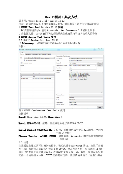
Onvif测试工具及方法版本号:Onvif Test Tool Version 12.12用途:测试网络设备(网络摄像机、NVR、解码器等)是否支持ONVIF验证1 ONVIF Test Tool Version 12.12安装1.PC安装环境要求:装有Microsoft .Net Framework 3.5或以上版本。
1.安装源文件:ONVIF官网下载或联系美佳威迪欧电子技术售后人员咨询2 ONVIF Device Test Tools 使用2.1 ONVIF Device Test Tool 12.121)Discovery - 搜索在线的支持Onvif 协议的网络设备如图1:图1 ONVIF Conformance Test Tools 使用上图说明:Brand: Megavideo (品牌:Megavideo )Model: MPV-073-3X (型号:美佳威迪欧电子的MPV-073-3X)Serial Number: 00d08907f23a ( 编号:美佳威迪欧电子的Mac地址,全球唯一的IP地址)Fimware Version:mv20121102NSA (固件版本:MegaVideo 的网络摄像机的固件版本)2.3 结论如果通过上述工具可以搜到该设备,说明此设备支持ONVIF协议。
如果厂家说明书或厂家销售人员说该厂设备支持ONVIF,但是搜索不到,可以通过IE或厂家自己的配置工具登陆该设备,看ONVIF支持是否开启,有些厂家的设备只能支持一个通讯接入协议,ONVIF支持是可选的,美佳威迪欧电子(香港)实业有限公司的网络摄像机、NVR由于采用世界顶级的核心处理芯片(美国安霸Ambarella Soc & SONY Xarina Soc),具有足够的主频冗余及强大的运算能力,可以同时进行多种运算、图像压缩处理,亦可同时支持威迪欧电子的私有协议及Onvif 标准协议。
斯泰格电子 EPD系列电子价签 使用手册说明书

Client confirmationClientReview Review dateIf the receipt specification is not signed within 15days,the consignee willagree.Prepared by Check ApprovedMODE:SETHB0213REPD Series Price Tag SpecificationRevision historyVersion Date Description Operator 002019.01.17First edition1.Product descriptionSETHB0213R electronic price tag product has the characteristics of real-time price change,information synchronization,time-of-day promotion,and can realize functions such as product positioning,product recommendation,picking,marketing and implantation,and increasing the product and the operator,customers,and brands Business interactivity.At the same time,it combines online platforms to implement product evaluation and mobile cashiering,which is widely used in various retail scenarios.(SETHB0213R front view)2.Product characteristics2.1Screen AreaDescription of display material:Dot-matrix electronic ink screen,providing black and white dual color or black white and red tricolor displayThe display angle is close to180degrees,and the display contrast isgreater than8:1Description of display content:Supports all normal display content of the"Price Tag Law"Rich display content,support text,picture,one-dimensional code,two-dimensional code display(two-dimensional code display content in the range of20mm *20mm greater than75characters)multi-language environment,display templates can be customized by customers.Display power-off maintenance time:more than6monthsDisplay afterimage:no afterimage after updating display,no afterimage after strong squeezeDisplay material stability:E-paper screen factory shipped3million pieces in the past year2.21D barcode areaPrice tag ID,18-digit barcode area for product binding and maintenance2.3LED light areaLED lights can display multiple colors for reminders of price tag status,such as out of stock,picking,inventory inspection,etc.2.4Power supplyPowered by Coin cell battery,The lifespan is5years with four price updates per day.2.5Communication ModeCommunication frequency:2.4GHzCommunication mode:full duplex/two-way communication mode Communication distance:more than20meters Communication bit error rate:less than one ten million2.6Communication rate18,000price updates per hour,communication success rate100%.2.7Product overall application standardsOperating temperature range:normal temperature screen0-30℃Storage temperature range:normal temperature screen0-40℃Product protection:a certain degree waterproof,moisture-proof and anti-collision functions.Color matching:Combined with the overall design of the store.A variety of installation methods:rail,suspension,swing table,hook type to meet thedisplay needs of different environmentsAnti-theft requirements:Reliable physical anti-theft solutions 3.Product specificationsItem Description Unit Product size65(H)×35(V)×13.6(D)mm Product weight31g Product appearance Silver grey--Display size 2.13Inch Screen Resolution212(H)×104(V)Pixel Viewing direction180°Display effect EPD dot matrix electronic paper black andwhite or black white and red--Lighting function Multicolor LED--Battery operating life5years(4price updates per day)--Battery specifications2×CR2450Battery capacity600mAh Battery replaceability Replaceable battery pack--Operating temperature0-30℃Stored temperature0-40℃Package160Pcs/carton Certificate CE,ROHS--Transmission frequency 2.4GHz Transfer speed18000PCS/hour 4.Product Design Drawing5.Reliability test5.1Free fall test5.1.1Test Conditions⏹Test height:1.60M⏹Ambient temperature:25±2°C⏹Ground:smooth concrete ground⏹Number of samples:32pcs⏹Inspection equipment:tape measure5.1.2Testing method⏹The tested product is not packaged,without accessories,and is in working state.⏹From a height of1.6M(if the LCM area exceeds60%of the product surface area,Drop height is50CM),initial velocity is0and free fall on smooth coagulation On the ground,each side fell3times,and the6sides totaled18times.Remove the sample for inspection after the test.5.1.3Test results⏹After testing,the basic functions and performance are normal,and the appearance and structure are normal.5.2High and low temperature test5.2.1Test Conditions⏹Test temperature:-24℃~+55℃⏹High temperature parameters:high temperature55±2℃humidity80%RH time:8hrs⏹Low temperature parameter:low temperature-24±3℃humidity80%RH time:8hrs⏹Number of samples:32PCS⏹Inspection equipment:high and low temperature experiment box5.2.1Testing Method⏹High temperature test:The test product is not packaged and in a working state;Put it into the test box at the normal position,and make the temperature reach+55±3℃After the temperature is stable,it will last for8hours.After the duration expires,the product will be inspected after testing⏹Low temperature testThe product under test is not packaged and in a working state;Put it into the test box at the normal position to make the temperature reach-24±2℃;After the temperature stabilizes,it lasts for8hours,and the duration expires,andthe inspection after the product test is performed.5.2.3Test Results⏹After testing,the basic functions and performance are normal,and the appearance and structure are normal.5.3Random vibration test5.3.1Test Conditions⏹Test temperature:ambienttemperature:25±2°C⏹High frequency range:20-500Hz,powerspectrum degree0.96M2/S3time:3hrs⏹Low frequency range:5-20Hz,powerspectrum degree0.96M2/S3time:3hrs⏹Number of samples:32PCS⏹Inspection equipment:Vibration meter5.3.2Testing method⏹The tested sample is not packed,is in a state of power,and is firmly fixed on the test bench;⏹Test parameters:frequency range5-20Hz,power spectrum0.96M2/S3;20-500Hz,power spectrum0.96M2/S3(at20Hz),other-3dB/℃T⏹Axial:three axes,duration,1hour,3hours in each direction,the end of duration, remove the prototype and check after testing.5.3.3Test Results⏹The structure is normal,and no loose orcracked parts are found.5.4Salt spray test5.4.1Test Conditions⏹Test temperature:ambient temperature:35±2°C⏹Test reagent:salt solution⏹Number of samples:32PCS⏹Inspection equipment:salt spray tester5.4.2Testing method⏹Salt solution is made of chemically pure sodium chloride and resistivity not less than 5000ohms*CM distilled water or deionized water.5parts by mass of sodium chloride and95parts by mass of water were thoroughly mixed to prepare a salt solution having a sodium chloride content of5±1%.⏹The pH value of the prepared salt solution after spraying at a temperature of35℃each time is6.5~7.2.It is permissible to adjust the pH value with diluted chemically pure hydrochloric acid or sodium hydroxide,and to detect the pH value,you can use a pH meter or a PH precision test paper.⏹In the effective space of the test,the clean collector at any position has a continuous spraying time of at least16H,an average of80CM2horizontal collection area(about 10CM in diameter)per hour,and a salt mist deposition amount of1-2ML.⏹The temperature in the effective space of the test is35°C,and the continuous spraying time of the test sample is at least48H.The test sample is restored to the normal test atmospheric conditions in the test box,and the appearance and functionare tested after the test sample reaches a stable temperature.5.4.3Test ResultsNormal function,normal appearance/structure 6.Power consumption test6.1Test tools1After the tag is powered on,the special test firmware will be swiped again within30s.(The measured data are the data of the second screen brush)2Multimeter:FLUKE18B+3Oscilloscope:Micsig To11024Resistance:8Ω5ENERGY EFM326Tag,button battery6.2Refreah screen pulse current test connection6.3Test Results6.3.1Sleep bottom currentSleep bottom current18uA6.3.2Freshing screen pulse Freshing screen pulse current21mA6.3.3Screen freshing average current and timeRefresh screen average current810uA refresh screen10s 6.3.4Scanning average current and scan timeScanning average current2.4mA Scan time88ms6.3.5Scan intervalScan interval15s7.RF test7.1Test toolsBluetooth tester,network analyzer7.2Test items7.2.1Transmit power⏹Package type:DH1⏹Modulation mode:PRBS9⏹Power type:average powerFrequency hopping mode:a.No frequency hopping:test channel0:fTX=2402MHz19:fTX=2441MHz39:fTX=2480MHzb.Frequency hopping:EU and US frequency hopping modes⏹Test limitMinimum–6dBmMaximum+4dBm7.2.2Modulation characteristics:frequency offset⏹Package type:DH1⏹Modulation mode:-00001111Mean frequency offsetΔf1avg-01010101Mean frequency offsetΔf2avg-01010101Maximum frequency offsetΔf2max⏹Frequency hopping mode:a.No frequency hopping:test channel0:fTX=2402MHz19:fTX=2441MHz39:fTX=2480MHzb.Frequency hopping:EU and US frequency hopping modes⏹Test limit:Δf1avg:min140kHzmax175kHzΔf2max:min115kHZΔf2avg/Δf1avg:Min0.87.2.3Initial carrier frequency tolerance⏹Package type:DH1⏹Modulation mode:PRBS9⏹Frequency hopping mode:a.No frequency hopping:test channel0:fTX=2402MHz19:fTX=2441MHz39:fTX=2480MHzb.Frequency hopping:EU and US frequency hopping modes⏹Test conditions:conventional test conditions and extreme test conditions⏹Test limit:Minimum Transmitting carrier frequency-75kHzMaximum Transmitting carrier frequency+75kHz7.2.4Sensitivity⏹Package type:DH1⏹Modulation mode:PRBS9⏹Hopping mode:No frequency hopping:test channel0:fTX=2402MHz39:fTX=2441MHz78:fTX=2480MHzFrequency hopping:EU and US frequency hopping modes⏹Test conditions:conventional test conditions and extreme test conditions⏹Test limit:Maximum0.1%7.2.5Sensitivity limit⏹Package type:DH1⏹Modulation mode:PRBS9⏹Frequency hopping mode:a.No frequency hopping:test channel0:fTX=2402MHz39:fTX=2441MHz78:fTX=2480MHzb.Frequency hopping:EU and US frequency hopping modes⏹Test conditions:conventional test conditions and extreme test conditions⏹Test limit:Max-70dBm8.Packaging8.1Use of tools and materialsNo.Material name Specifications Quantity Note 1Seal tape L×W×H=100×60×0.1mm2Foam partition L×W×H=365×333×4mm(SertagUniversal Box)3PCS/box3Tray L×W×H=355*265*23mm(electroniclabel)10PCS/plate4PE bag L×W×H=460×385×0.5mm(SertagUniversal Box)80PCS/bagNumber oftags inside5Pearl cotton(narrowsection)L×W×H=215*67*0.8(Under thenarrow section)mm40PCS/box6Pearl cotton(wide section)L×W×H=215*67*0.8(Widesection)mm40PCS/box7Packaging L×W×H=375*275*230mm(SertagUniversal Box)160PCS/boxNumber oflabel boxes8.2Flow chart8.2.1Products are placed inorder8.2.2Neatly placed layers (5layers ofproducts +1layer empty)8.2.3Put in PE bag and put 2bags ofdesiccant8.2.4Vacuum packaging machine vacuum,refer to [vacuum packaging operation guide]8.2.5Inner packaging label,confirm quantity date 8.2.6Put a layer of foam on the top and bottom of the outer box8.2.7Put two packages of products one after the other and fill the full case 8.2.8Tape"H"type packaging outer packing box8.2.9Adhesive packaging label,8.2.10Carton label descriptionconfirm quantity dateBusiness offerAccording topackaging SOPQuality stampDelivery date。
ABI检测工具使用和解读步骤说明书

Ankle-Brachial Index: A Diagnostic Tool for Peripheral Arterial DiseaseStep-by-step instructions on how to perform and interpret the ABIWhat is the ABI? The ankle-brachial index (ABI) is a simple, noninvasive tool used to screen for peripheral arterial disease (PAD), a vascular condition affecting more than 8 million adult Americans and associated with significant morbidity and mortality.[1] Despite its prevalence and cardiovascular risk implications, only 25% of PAD patients areundergoing treatment.[1] As only about 10% of patients with PAD present with classic claudication—40% of patients are asymptomatic—clinicians need to have a high level of suspicion for this disease in their adult patient population.[2] According to AHA/ACCguidelines, an ABI should be conducted on patients presenting with risk factors for PAD so that therapeutic interventions known to diminish theirincreased risk of myocardial infarction (MI), stroke,and death may be offered.[2] (Level of Evidence: B) Age >70 yr Age >50 yr if atherosclerosis risk - Smoking- Diabetes - Hypertension - Dyslipidemia - Hyperhomocysteinemia Sphygmomanometer with appropriately sized cuff(s) for both arm and ankle Handheld Doppler device with vascular probe Conductivity gel compatible with the Doppler device How to perform the ABI. Measurement of the ABI can be easily performed in a clinician’s office using a blood pressure (BP) cuff and handheld Doppler device with a vascular probe. Systolic BP is determined in both arms and both ankles. An ABI measurement can usually be performed in less than 10 minutes.Step 1: Measure the brachial systolic pressure in both arms[3,4]:Allow patient to rest for 5-10 minutes in the supine position.Place the BP cuff on patient’s upper arm with the lower edge approximately 1 inch above theantecubital fossa.Palpate for the brachial pulse and apply conductivity gel over the brachial artery. Place thetip of the probe into the gel at a 45-60-degree angle until clear arterial pulse sounds are heard. Inflate the cuff to the point that pulse sounds disappear, then go 20 mm Hg above that point.Slowly deflate at a rate of 2 mm Hg per sec and record the point where arterial pulse sounds resume. This is the brachial systolic pressure.Repeat this procedure in the other arm.The higher of the two brachial systolic pressure readings will be used to calculate the ABI.There should be a difference of less than 10 mm Hg between each brachial BP.Tools Needed for Measuring ABIRisk Factors for PADSelect the higher of the two ankle readings for each leg (PT or DP). These numbers will serve as the ankle systolic pressures in the ABI calculation.If either the PT or DP ankle pulse is absent, use the measurable reading to calculate the ABI. Step 3: To calculate the ABI, divide each ankle systolic pressure by the brachial systolic pressure. Divide the higher of the two systolic pressures for each leg by the higher of the two arm pressures to get the right and left ABI.For example, consider the results at the right. The ABI for this patient is calculated by using 130 (the higher of the two brachial pressures) as the denominator and 95 and 130 as the numerators for the right and left legs, respectively. The ABI for the right leg is 0.73 and for the left leg is 1.0.How to interpret the ABI.An abnormal ABI may be an independent predictor of mortality, as it reflects the burden of atherosclerosis.[5,6] Most will agree that a normal ABI is >0.9. An ABI <0.9 suggests significant narrowing of one or more blood vessels in the leg. The majority of patients with claudication have ABIs ranging from 0.3 to 0.9. Rest pain or severe occlusive disease typically occurs with an ABI <0.5. ABIs <0.2 are associated withischemic or gangrenous extremities. Conditions such as diabetes mellitus or end stage-renal disease can give falsely elevated ABIs (1.3-1.5). The ABI test approaches 95% accuracy in detecting PAD.[7] However, a normal ABI value does not absolutely rule out the possibility of PAD. Some patients with normal or near-normal ABI results may have symptoms suggesting PAD. If the resting ABI is normal, an exercise ABI should be conducted.ABI Key Normal : 1.0 - 1.1 Borderline : 0.91 - 0.99 Abnormal : <0.9 or >1.3Ask your patients about leg pain and measure ABI in all patients at risk for PAD.References1. American Heart Association. Statistical Fact Sheet—Miscellaneous, 2008 Update. Peripheral Arterial Disease—Statistics. /downloadable/heart/1198011637413FS26PAD08.REVdoc.pdf.2. Hirsch AT, et al. ACC/AHA 2005 Practice Guidelines for the Management of Patients With Peripheral Arterial Disease (Lower Extremity, Renal, Mesenteric, and Abdominal Aortic): Executive Summary. Circulation .2006;113:1474-1547.3. Perloff D, et al. Human blood pressure determination by sphygmomanometry. Circulation 1993;88;2460-70.4. Pickering TG, et al. AHA Scientific Statement. Recommendations for Blood Pressure Measurement in Humans and Experimental Animals Part 1: Blood Pressure Measurement in Humans. Circulation . 2005;111:697-716.5. Feringa HH, et al. The long-term prognostic value of the resting and postexercise ankle-brachial index. Arch Intern Med 2006;166:529-35.6. Wild SH, et al. Low ankle-brachial pressure index predicts increased risk of cardiovascular disease independent of the metabolic syndrome and conventional cardiovascular risk factors in the Edinburgh Artery Study. Diabetes Care 2006;29(3):637-42.7. Vascular Disease Foundation. PAD: Diagnosis: ABI. 2008. /diseaseinfo/pad/anklebrachial.php. Step 2: Measure the posterior tibial and dorsalis pedis systolic pressures in both legs:Place the BP cuff on the patient’s leg approximately 2 inches above the ankle’s medial malleolus.Locate the posterior tibial (PT) pulse, apply gel, and position the Doppler probe. Measure the systolic pressure following the same procedure described for the brachial artery.On the same leg, locate the dorsalis pedis (DP) pulse and measure systolic pressure.Repeat measurement of both the PT and DP systolic pressures on the other leg.。
tessy单元测试使用手册
tessy单元测试使用手册Tessy 是一款针对嵌入式软件进行单元和集成测试的工具,主要用于测试C/C 代码。
以下是Tessy 单元测试的基本使用手册:1. 安装Tessy请根据Tessy 的官方文档进行安装。
通常,您需要安装Tessy 服务器和Tessy 客户端。
安装过程中需要设置环境变量,以确保正确识别Tessy 相关文件。
2. 创建测试项目在Tessy 中,创建测试项目是通过对代码进行分析来完成的。
首先,使用Tessy 提供的代码分析工具(如ctags)分析代码,生成源代码列表。
然后,在Tessy 客户端中创建测试项目,并为代码中的每个函数分配唯一的ID。
3. 编写测试用例针对每个函数,编写相应的测试用例。
测试用例包括输入参数、预期输出和实际输出。
测试用例可以通过Tessy 客户端直接编写,也可以使用Te ssy 提供的模板生成。
4. 配置测试在Tessy 客户端中,为每个测试用例配置测试参数,如测试次数、测试间隔等。
此外,您还可以配置测试执行顺序、测试暂停条件等。
5. 执行测试在Tessy 客户端中,启动测试执行。
Tessy 会将测试用例自动发送到Tessy 服务器,并在服务器上执行。
测试过程中,Tessy 会记录测试结果、生成测试报告。
6. 分析测试报告查看测试报告,分析测试结果。
报告包括测试执行情况、代码覆盖率、异常信息等。
根据报告,您可以发现潜在的错误和问题,并对代码进行修改。
7. 迭代优化根据测试结果,修复代码中的问题,并重新执行测试。
在迭代过程中,不断优化代码,提高软件质量。
注意:Tessy 的具体使用方法可能因项目需求和配置而有所不同。
建议参考Tessy 官方文档和教程,以了解更多详细信息。
测试工具的使用说明
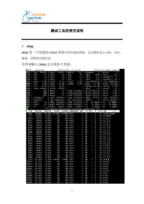
测试工具的使用说明1. atopatop是一个高级的Linux系统全屏性能监视器,会定期的显示CPU、内存、磁盘、网络的负载信息。
在终端输入./atop会出现如下界面:在界面中键入‘m’,就会显示每个进程的内存情况,如下图:在界面中键入‘s’, 就会显示与调度有关的进程信息,如下图:在界面中键入‘v’,就会显示每个进程的全部信息,如下图:在界面中键入‘c’,就会显示每个进程的命令行,如下图:2.bonnie++1.使用说明-d:在测试时会生成一些文件,并读或更改这些文件。
这个参数是设置测试文件放置的路径。
-s:单个测试文件的尺寸。
这个参数值必须大于等于2倍测试使用的内存。
测试时应该用大文件尺寸。
-m:测试的机器名称-r:测试需要用多少内存。
如果省略这个值,则会用全部的物理内存。
-x:循环几次-u:指定执行测试的OS用户。
当不是以root执行时,必须显式指定。
-g 测试文件的组,默认是执行bonnie++的当前用组。
-b 在每次写文件时调用fsync()函数,对于测试邮件服务器或者数据库服务器这种通常需要同步操作的情况比较适合,而不使用该参数则比较适合测试copy文件或者编译等操作的效率。
2.结果分析下面看一个测试结果,通过这个结果我们解释一下到底bonnie++在测试过程中都作了什么,而每一个输出的结果又表示了什么。
依次解读一下,从Writing with putc()开始到Delete files in random orde…结束,这是bonnie++作的12项测试,这12项测试依次对应12项结果,而这12项结果又被分为了5大类,分别是Sequential Output(写测试),Sequential Input(读测试),Random Seeks(读写测试),Sequential Create(顺序读写文件测试)和Random Create(随意读写文件测试)。
那么测试步骤和测试结果依次对应的顺序就是:Writing with putc() -> Sequential Output的Per ChrWriting intelligently -> Sequential Output的BlockRewriting -> Sequential Output的RewriteReading with getc() -> Sequential Input的Per ChrReading intelligently -> Sequential Input的Blockstart 'em -> Random SeeksCreate files in sequential order -> Sequential Create的Create Stat files in sequential order -> Sequential Create的ReadDelete files in sequential order -> Sequential Create的Delete Create files in random order -> Random Create的CreateStat files in random order -> Random Create的ReadDelete files in random order -> Random Create的Delete每个结果中又包括了2项数值,一个是K字节数或者文件数,另一个是%CP,就是执行这项测试时CPU的平均占用率。
ATE_Tool工具说明书SC15-003
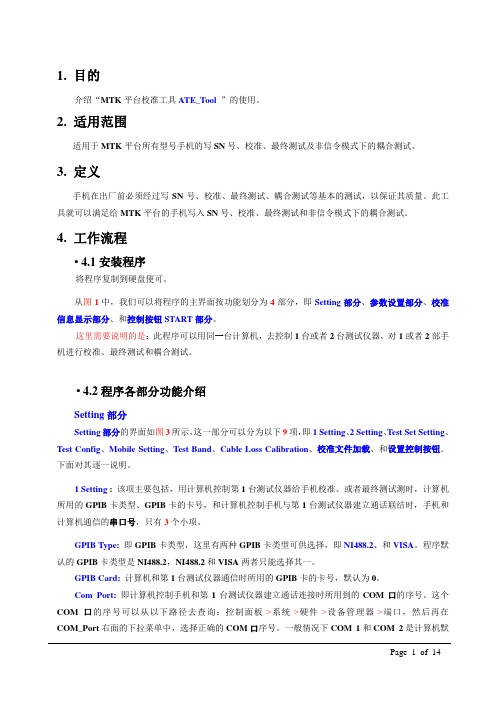
1. 目的介绍“MTK平台校准工具ATE_T ool ”的使用。
2. 适用范围适用于MTK平台所有型号手机的写SN号、校准、最终测试及非信令模式下的耦合测试。
3. 定义手机在出厂前必须经过写SN号、校准、最终测试、耦合测试等基本的测试,以保证其质量。
此工具就可以满足给MTK平台的手机写入SN号、校准、最终测试和非信令模式下的耦合测试。
4. 工作流程• 4.1安装程序将程序复制到硬盘便可。
从图1中,我们可以将程序的主界面按功能划分为4部分,即Setting部分、参数设置部分、校准信息显示部分、和控制按钮ST ART部分。
这里需要说明的是:此程序可以用同一台计算机,去控制1台或者2台测试仪器,对1或者2部手机进行校准、最终测试和耦合测试。
• 4.2程序各部分功能介绍Setting部分Setting部分的界面如图3所示,这一部分可以分为以下9项,即1 Setting、2 Setting、T est Set Setting、T est Config、Mobile Setting、T est Band、Cable Loss Calibration、校准文件加载、和设置控制按钮。
下面对其逐一说明。
1 Setting :该项主要包括,用计算机控制第1台测试仪器给手机校准、或者最终测试测时,计算机所用的GPIB卡类型、GPIB卡的卡号,和计算机控制手机与第1台测试仪器建立通话联结时,手机和计算机通信的串口号,只有3个小项。
GPIB T ype: 即GPIB卡类型,这里有两种GPIB卡类型可供选择,即NI488.2、和VISA。
程序默认的GPIB卡类型是NI488.2,NI488.2和VISA两者只能选择其一。
GPIB Card: 计算机和第1台测试仪器通信时所用的GPIB卡的卡号,默认为0。
Com Port: 即计算机控制手机和第1台测试仪器建立通话连接时所用到的COM口的序号。
这个COM口的序号可以从以下路径去查询:控制面板->系统->硬件->设备管理器->端口,然后再在COM_Port右面的下拉菜单中,选择正确的COM口序号。
testo 175 T2 - 使用说明书

Contents / General information8ContentsGeneral information ..................................... 8Safety guidelines ......................................... 9Overview ..................................................... 10Commissioning / Cleaning ........................... 11Technical data ............................................. 12What to do if... ............................................. 13Spare parts .................................................. 13Accessories . (13)General informationSymbols usedindicates notes that you must read - for your own safety, the safetyof others and to protect your meter from being damaged.indicates notes that inform you of special features.Accuracy when going to pressThe use of advanced technology and the high quality standard of our instruments are the result of continuous development. This may result in differences between thisoperating manual and your instrument. We cannot guarantee that there are absolutely no errors in this manual. We are sure you will understand that we cannot accept any legal claims resulting from the data, figures or descriptions.WarrantyThe designated instrument is covered by a warranty of 12 months from the date of purchase.The instrument warranty extends to manufacturing faults that are determined within the period of warranty. The warranty claim extends to restoring the instrument to readiness for use but not, however, to any further claim for damages. Improper handling or unauthorized opening of the instrument invalidates any warranty claim.To ascertain the warranty liability, return the instrument and proof of purchase together with the date of purchase freight paid or prepaid.Safety guidelines9Safety guidelinesRead these safety guidelines carefully before putting the instrument into operation!This instrument has been built and tested according to the IEC 1010 safety standards for electronic measuring instruments and has left our works in a condition complying with all the requirements of technical safety.The perfect functioning and operational safety of the instrument can only be ensured if the user observes the normal safety precautions as well as the specific safety guidelines stated in the present operating instruction.ATTENTION: MAGNETISM!Effects of the magnetic field have to be taken into account (e.g. with cardiac pacemakers, data carriers...).• Before connecting the plug-in power supply unit to the electricity supply networkit must be ensured that the operating voltage stated on the plug-in power supply unit corresponds to the mains voltage (statement of the supply voltage range).• The perfect functioning and operational safety of the instrument can only bemaintained under the climatic conditions specified in the "Technical data" section of these operating instructions.• When the instrument is moved from cold to warm surroundings, condensate mayoccur and interfere with the functioning of the instrument. In such a case, theuser should wait until the temperature of the instrument has adapted to the ambient temperature before using the instrument again.• Balancing, maintenance and repair work must only be carried out by a suitablyqualified technician authorized by us.• If there is reason to assume that the instrument can no longer be employed withouta risk, it must be set aside and appropriately marked to prevent further use.• The safety of the user may be endangered, e.g., if the instrument-shows visible damage,-no longer operates as specified,-has been stored over a longer period under unsuitable conditions,-has been subjected to difficult conditions during transport.• If in doubt, the instrument should as a rule be sent back to the manufacturer's -"Wissenschaftlich-Technische Werkstätten GmbH" - for repair and maintenance.Overview10OverviewThe IS 6 – Var Stirring System has been especially developed for the WTW OxiTop â.All commercial sample bottles up to max. 93 mm bottom diameter can be used.The stirring procedure is activated by a magnetic rotary field. This rotary field activates the permanently magnetic stirring rods.The electronic interval control of the rotary field allows• To place sample bottles on the stirring system at any time• Disturbed stirring procedures to restart independently while the measuringoperation is running.121Stirring power switch-over 2Line adaptor connectionFor BOD measurements with OxiTop âsystems the stirring power should be set to …Low Power“, as the higher power causes the temperature of the sample to rise.Commissioning / Cleaning11CommissioningUse the original line adaptor only.The mains voltage must correspond to the operating voltage stated on the line adaptor!–Place the stirring system into a thermostat cabinet or a thermostat box.–Plug the line adaptor into the mains socket.– Connect the line adaptor to the instrument (2).After a waiting time of approx. 3 s the inductive rotary field is automatically built upand thus the stirring rods are activated.To guarantee an optimal and secure stirring function, use only original WTW stirring rods, RST 600.– Place the prepared sample bottles on the center of the stirring places designed.– Observe stirring operation, if necessary correct bottle position.Operating noteVia the Stirring power switch-over (1) you can adjust the stirring power to meet the requirements of the sample.When working with increased stirring power (“High Power“), theelectronically controlled rotary field is operated with increased power. This causes an increased self-warming. If a perfect stirring operation ispossible with reduced stirring power, work with “Low Power“ preferably.Cleaning– Clean with a soft cloth and aqueous soap solution.Do not use solvents or detergents that contain solvents (e. g. alcohol, acetone) for cleaning.Technical data12Technical dataFunction principleMagnetic rotary fieldPower supply (Line adaptor)Euro version:USA version:Friwo FW6798/11.8369,Friwo Part. No. 1769278Input:230 VAC (+10%/-15%)/ 50/60 Hz / 24 VA Output:18 VAC / 1 A Friwo FW6798/11.8371,Friwo Part. No. 1769294Input:120 VAC (+10%/-15%)/ 50/60 Hz / 23 VA Output:18 VAC / 1 A Power consumption 24 VA max.Number of stirring places 6Diameter of vessel bottom max. 93 mmSpeed of stirring rods Program-controlled 180 ... 450 min -1Instrument securityProtection class: 3, IEC 1010Protection degree: IP30EMCEmissions:EN50081-1/FCC class A Immunity:EN50082-1EN50082-2, NamurClimate class 2, VDI/VDE 3540Ambient temperature Storage: - 25 °C ... + 65 °C Operation: + 5 °C ... + 40 °C Relative humidityYearly mean:< 75 %30 days/year:< 95 %Other days:< 85 %Test markCEDimensions (WxDxH)350 x 266 x 70 [mm]Weight (including line adaptor) 3.2 kgWhat to do if...13What to do if...ErrorCauseActionNo stirring function– Mains power missing – Line adaptor defective – Stirring system defective– Connect stirring system to power supply via line adaptor – Replace line adaptor– Send stirring system to servicedepartment Stirring function not sufficient– Stirring rods unsuitable– Vessel bottom weakens the magnetic field (vessel bottom is too thick, crooked, or deformed)– Use original WTW stirring rods– Use suitable vessel Centering of stirring rods faulty– Vessel is not placed centrically on the stirring system– Vessel bottom is too thick, crooked, or deformed– Magnetic field is too weak– Adjust vessel position– Use suitable vessel– Send stirring system to service departmentSpare partsModelOrder no.Stirring rods RST 600209 120Stirring rod removerREF 600209 130AccessoriesThe accessories that can be supplied are described in the WTW general catalog and in the price list.。
ONVIF测试方法及工具
设备是否支持ONVIF验证1 ONVIF Test Tool安装1.1PC安装环境要求:装有Microsoft .Net Framework 3.5或以上版本。
1.2安装源文件请见:ONVIF Conformance Test Tools.rar2 ONVIF Conformance Test Tools 使用2.1 ONVIF Conformance Test Tool 1.01)Setup如图1:图1 ONVIF Conformance Test Tools 使用说明:Test Device Information和Test Information内的数字可以任意添。
2)搜索进入Management栏,如图2所示:图2 ONVIF Conformance Test Tools 使用点击“Discover Devices”按钮搜索即可。
3)搜索结果查看如果可以搜到(有的厂家设备反应较慢,可以多搜几次看看),在“Discover Devices”按钮右侧就会列出搜索结果列表,如图3红色框内所示:图3 ONVIF Conformance Test Tools 使用点击列表中任意一个设备,右下角会显示其对应信息。
如图4红色框内所示:图4 ONVIF Conformance Test Tools 使用此时输入用户名和密码后(设备自身的用户名和密码,有的厂家设备不需要),点击“Check”按钮,一般情况下会跳出设备基本信息,如图5所示:图5 ONVIF Conformance Test Tools 使用如图5可以看到此设备一些基本信息。
如:Firmware version(固件版本)、Hardware ID(硬件ID)、Manufacturer(厂商)、Model(型号)、Serial Number(序列号)等。
2.2 ONVIF Conformance Test Tool 1.02.3.5ONVIF Test Tool version 1.02.3.5使用方法与1.0类似,只是界面有些改动,如下图6与图7所示:图6 ONVIF Conformance Test Tools 使用图7 ONVIF Conformance Test Tools 使用2.3 结论如果通过上述两个工具(或其一)可以搜到该设备,说明此设备支持ONVIF。
TestSoftV1.1软件说明书

目录第1章安装和运行 (3)1.1 运行环境 (3)1.2 安装 (3)1.3 卸载 (4)第2章简介 (5)2.1 功能简介 (5)2.2 界面简介 (5)2.2.1 系统菜单 (5)2.2.2 工具栏 (17)2.2.3 示值显示栏 (18)2.2.4 试验参数 (19)2.2.5 试验过程 (20)2.2.6 多图曲线 (20)2.2.7 试验信息 (21)2.2.8 试验步骤 (22)2.2.9 结果处理 (23)2.2.10 速度显示栏 (24)2.2.11 状态栏 (25)第3章如何完成第一个试验 (26)3.1 启动软件 (26)3.2 新建试验 (26)3.3 填写试验前参数 (26)3.4 装夹试样 (26)3.5 运行试验 (26)3.6 观察试验 (27)3.7 结束试验 (27)3.8 卸下试样 (27)3.9 查询 (27)3.10 报告打印 (27)3.11 退出程序 (27)第4章试验 (28)4.1 试验前设置 (28)4.2 拉伸试验 (28)4.2.1 打开试验软件,进入程序 (28)4.2.2 新建试验 (28)4.2.3 输入试验参数 (28)4.2.4 清零 (28)4.2.5 装夹试样 (28)4.2.6 装夹引伸计 (29)4.2.7 运行 (29)4.2.8 试验结果 (29)4.2.9 试验后解释 (30)4.3 抗压试验 (30)4.3.1 打开试验软件,进入程序 (30)4.3.2 新建试验 (30)4.3.3 输入试验参数 (31)4.3.4 摆放试样 (31)4.3.5 运行试验 (31)4.3.6 试验后结果 (31)第5章分析试验 (32)5.1 查找试验记录 (32)5.2 观察试验分析曲线图 (32)5.2.1 加入移出曲线 (33)5.2.2 更改曲线坐标轴 (33)5.2.3 曲线缩放平移 (33)5.3 自定义报告 (34)5.4 试验前参数 (34)5.5 试验后参数 (34)5.6 参数点 (35)5.6.1 修改参数 (35)5.6.2 重新计算 (38)5.6.3 清除特征 (38)第6章校准及检定 (39)6.1 检定界面介绍 (39)6.1.1 检定点设定 (39)6.1.2 自定义检定方式 (40)6.1.3 显示检定结果 (40)6.1.4 更改标定参数 (41)6.2 力值检定 (42)6.2.1 检定步骤: (42)6.2.2 修正步骤: (43)第1章安装和运行1.1运行环境计算机硬件配置:打印机配置:支持各种打印机;计算机操作系统配置:中文,英文windows 98/2000/XP操作系统1.2安装1.双击打开光盘中setup.exe文件,程序就会自动开始安装;图1:软件初始界面2.在接下来的出现的窗口中,点击“下一步”,出现安装路径选择窗口;图2:安装确认界面3.在安装路径选择窗口设置路径,点击“下一步”。
TestLodge测试管理工具教程说明书

About the T utorialTestLodge is a test management tool that is used to track and maintain records of all STLC phases from Test Plan to Report creation. This is a brief tutorial that introduces the readers to the basic features and usages of TestLodge.This tutorial will guide users on how to utilize TestLodge in reporting and maintaining the testing activities.AudienceThis tutorial has been prepared for beginners to help them understand how to use the TestLodge tool.PrerequisitesAs a reader of this tutorial, you should have a basic understanding of the testing life cycle. Copyright &DisclaimerCopyright 2018 by Tutorials Point (I) Pvt. Ltd.All the content and graphics published in this e-book are the property of Tutorials Point (I) Pvt. Ltd. The user of this e-book is prohibited to reuse, retain, copy, distribute or republish any contents or a part of contents of this e-book in any manner without written consent of the publisher.We strive to update the contents of our website and tutorials as timely and as precisely as possible, however, the contents may contain inaccuracies or errors. Tutorials Point (I) Pvt. Ltd. provides no guarantee regarding the accuracy, timeliness or completeness of our website or its contents including this tutorial. If you discover any errors on our website or in this tutorial,******************************************T able of ContentsAbout the Tutorial (i)Audience (i)Prerequisites (i)Copyright &Disclaimer (i)Table of Contents .......................................................................................................................................... i i1.TESTLODGE ─ INTRODUC TION (1)2.TESTLODGE ─ FEATURES (3)Core Features (3)3.TESTLODGE ─ FREE TRI AL ACCESS (5)Set Up for Free Trials (5)4.TESTLODGE ─ LOGIN (9)On Error (10)On Successful Login (11)5.TESTLODGE ─ DASHBOAR D (12)6.TESTLODGE – ADD USERS (14)7.TESTLODGE ─ ADD A PR OJECT (16)Create a Project (16)8.TESTLODGE ─ TEST PLA NS (19)Create a Test Plan (19)Edit a Test Plan (23)Move a Section (24)Delete a Section (24)9.TESTLODGE – COPY A TEST PLAN (26)10.TESTLODGE - REQUIREMENTS (29)Create a New Requirement (29)Edit a Requirement (32)Move a Requirement (33)Delete a Requirement (33)11.TEST LODGE ─ COPY REQUIRE MENTS (35)12.TESTLODGE ─ TEST SUI TES (39)Create a Test Suite (39)Create Test Cases (40)Edit a Test Case (42)Move a Test Case (43)Delete a Test Case (44)13.TESTLODGE ─ COPY TES T CASES (45)14.TESTLODGE ─ IMPORT T EST CASES (48)Import the File (48)15.TESTLODGE ─ ADD TEST RUN (53)16.TESTLODGE ─ EXECUTE A TEST RUN (59)Execute Test Runs (59)Re-Run Tests (62)17.TESTLODGE – TEST RUN SUMMARY (64)Individual Test Suite/Case Summary (66)18.TESTLODGE ─ REPORTS (70)Test Run Results (70)Common Case Results (72)User Workload (73)Traceability Matrix (74)19.TEST LODGE ─ EXPORT CONTE NTS (76)Export a Test Plan (76)Export Requirements (78)Export a Test Suite (79)Export Test Run Summary (79)20.TESTLODGE – ISSUE TRACKER INTEGRATION (81)Configuration (81)21.TESTLODGE ─ SEARCH (84)Search a Project (84)Search Test Plans (84)Search Test Suites (86)Search Test Runs (88)22.TESTLODGE ─ LOGOUT (89)1TestLodge is a cloud-based test case management tool used for Project Management and test management. It simplifies the testing process. It provides an easy way to organize, collaborate, and track the progress of tests.This tool is used to write and manage test plans as well test cases. It was developed by 6-member team. TestLodge CEO is Scott Sherwood.TestLodge is a cloud-based tool and supports all browsers especially Chrome, Firefox, IE, etc. It supports different Windows OS such as Windows XP, Windows Vista, Windows 7, etc. It can be integrated with many other tools – JIRA, Mantis, Bugzilla, FogBugz, Version One, GitHub, codebase, TFS, etc.License and Free TrialThis is a commercial tool and is available as a Trial version for limited time of 30 days for all accounts – Premium, Plus, Basic, and Personal. To utilize TestLodge services beyond 30 days, a license is required. TestLodge provides a free license for 30 days.Uses∙ Used in tracking all QA activities from the first phase of software testing lifecycle.∙ Useful in Project Management, Requirement Management, and Test Management.∙ Supports all test level activities performed by QA.∙Useful in performing QA tasks such as writing Test Cases, execution, reports, etc.TestLodge Specifications1.23TestLodge has a wide range of features to attract QAs and other stakeholders for test management.Core FeaturesFollowing are the core features of TestLodge. 2.45TestLodge provides 30-days free trials to email, access to unlimited users, with basic features. It has other plans as well with different advanced features and add-ins. Cost depends on different plans.Visit https:// and click Pricing & Sign Up. The user can view different available plans for trial.Set Up for Free T rialsFollowing are the steps to be followed to set up for free trials.Step 1: Visit https:// and click Pricing & Sign Up at the top right side corner of the screen.Step 2: Click “Sign Up” based on the choosen plan as shown in the following screenshot.3.6A basic form to create a TestLodge account pops up.Step 3: Enter the following details in the respective fields as shown in the following screenshots.∙First Name∙Last Name∙Email∙Create your TestLodge site addess: It should be unique and this URL will be used to access TestLodge application.∙Password: To authenticate access of this URL.∙Re-type password7Step 4: After entering all details, click “Create my account” as shown in the above screenshot. It will display a Thank you page of the New User as shown in the following screenshot.8Step 5: Enter the URL and after a few seconds, you will see the Login Page.The following screenshot displays the Login page where you can enter the details to visit the home page.9Following are the steps to login to TestLodge.∙Step 1: To login to TestLodge, go to your sample website selected while creating the free trial. It will open a login page.∙ Step 2: Enter your registered email address as username and enter the Password.∙Step 3: Click the Log In button.The following screenshot shows how to login into TestLodge using credentials.4.10On ErrorAn error may occur due to an incorrect combination of email id or password. You would get to see the following error page, as a result of an unsuccessful login or when the credentials are incorrect.If you forgot the password, then you can follow the steps given below to recover your password:∙Step 1: Click the “Forgot Your Password?” link below the Log In button.∙Step 2: Enter the Email Address.∙Step 3: Click the Send reset link.You can use the following page to recover the password, if you have forgotten it. You will get an email with the details of the username or a link to reset the password.11On Successful LoginOn successful login, the system dashboard will be displayed, if the account is associated with any project by admin or the user can create a sample project.The following screenshot displays the welcome page/dashboard of TestLodge on successful login.12End of ebook previewIf you liked what you saw…Buy it from our store @ https://。
Teledyne Test Tools T3AFG30 和 T3AFG60 功能 随机生成器说明书

Debug with Confidence30MHz–60MHzTeledyne Test Tools T3AFG30and T3AFG60range of function/arbitrary generators are a series ofdual-channel waveform generators with specificationsof up to60MHz maximum bandwidth,150M Sa/smaximum sampling rate and14-bit vertical resolution.The proprietary Arbitrary&Pulse techniques used in theT3AFG30/T3AFG60models helps to solve theweaknesses inherent in traditional DDS generators whengenerating arbitrary,square and pulse waveforms.Withthe above advantages the T3AFG30and T3AFG60generators can provide users with a variety of high fidelityand low jitter signals,which can meet the growingrequirements of a wide range of complex applications.Tools for Improved Debugging●●Deep Memory–16kpts/Ch.Generatecomplex arbitrary waveforms.Quickly set up modulated waveforms.●●Wide Range of Modulation Types–AM,DSB-AM,FM,PM,FSK,ASK,PWM,Sweep,Burst,and PSK.●●High Resolution–14bit resolution.Generatewaveforms with low noise,low spurioussignal content and high dynamic range.●●Bandwidth Models of30MHz and60MHz.Wide choice of bandwidths.Other modelsavailable up to500MHz.●●Built In Arbitrary Waveforms.Load and replay built in Arbitrary Waveforms.●●User Defined Waveforms.Store and recall user defined waveforms.Enquire about the T3AFG5and T3AFG10.●●Lower cost5MHz and10MHz single channel modelsare also available.Key SpecificationsOrderingInformationFunctionT3AFG30,T3AFG60Display Size4.3”Color TFTExcellent Performance●●Modelbandwidths from 30MHz to 60MHz●●All Models have 2Channels ●●16kpts/Channel memory Great Connectivity●●USBhostport for mass storage●●USB device port (USBTMC)●●LAN portThe rise/fall times can be set independentlyto a minimum of 16.8ns at any frequency and to a maximum of 22.4s.The T3AFG range of Function/Arbitrary Waveform Generators support a wide range of modulation types including AM,FM,PM,FSK,ASK,PSKandDSB-AM.Burstmode supports ‘N Cycle’and ‘Gated’modes with the Burst source being configured as ‘Internal’,‘External’or ‘Manual’.Output amplitude into a high impedance load can be as high 20Vpp at frequencies up to 10MHz,and 10Vpp for frequencies greater than 20MHz.Smart Capabilities●●Sweepoutput carrier can be Sine,Square,Rampand Arbitrary waveforms●●Burstoutput under internal or external signal control●●Waveforms types include DC●●FrequencyResolution 1µHz●●DSB-AM:Double Sideband AM modulation Function ●●HarmonicFunction generating up to 16harmonics●●Multi-LanguageUser InterfaceSweep mode supports ‘Linear’and ‘Log’sweep,with ‘Up’and ‘Down’direction,and Sweep source can be configured as ‘Internal’,‘External’or ‘Manual’.The counter functionality,accessed via the rear panel BNC,gives a DCor ACcoupled counter capability from 100mHz to 200MHz.The Teledyne Test Tools T3AFG30and T3AFG60,with its low jitter design,can generate waveforms with exceptional edge stability.With better jitter performance comes better edge stability,and higher confidence inyour circuit design.Sine wave output exhibits almost no spurious artefacts at 60MHz and 0dBm.Low JitterI/O Connectivity●●LAN and USB connection●●10MHz Reference Input/Output●●Aux Input/Output ●●External modulationinput ●●External burst/sweep trigger input●●External gate input●●TheAux Input/Output will output a trigger pulse when an internal source is used●●ExternalCounterinputFrequencySpecificationDC CharacteristicsModulation Characteristics–PWMSync OutputOrderinginformation©2018Teledyne Test Tools is a brand and trademark of Teledyne LeCroyInc.All rights reserved.Specifications,prices,availability and deliverysubject to change without notice.Product brand or brand names are trademarks or requested trademarks of their respective Company ProfileT eledyne LeCroyis a leading provider of oscilloscopes,protocol analyzers and related test and measurement solutions that enable companies across a wide range of industries to design and test electronic devices of all types.Since our founding in 1964,we have focused on creating products that improve productivity by helping engineers resolve design issues faster and more effectively.Oscilloscopes are tools used by designers and engineers to measure and analyze complex electronic signals in order to develop high-performancesystems and to validate electronic designs in order to improve time to market.The Teledyne Test Tools brand extends the Teledyne LeCroy product portfolio with a comprehensiverange of testequipment solutions.This new range of products delivers a broad range of quality test solutions that enable engineers to rapidly validate product and design and reduce time-to-market.Designers,engineers and educators rely on Teledyne Test Tools solutions to meet their most challenging needs for testing,education and electronics validation.Location and FacilitiesHeadquartered in Chestnut Ridge,New York,T eledyne Test Tools and Teledyne LeCroy has sales,service and development subsidiaries in the US and throughoutEurope and Asia.T eledyne T est T ools and T eledyne LeCroy products are employed across a wide variety of industries,including semiconductor,computer,consumer electronics,education,military/aerospace,automotive/industrial,and telecommunications.Teledyne LeCroy (US Headquarters)700Chestnut Ridge RoadChestnut Ridge,NY .USA10977-6499Phone:800-553-2769or 845-425-2000Fax Sales:845-578-5985Phone Support:1-800-553-2769Email Sales:*******************************Email Support:**************************Web Site:/Teledyne LeCroy(European Headquarters)T eledyne LeCroy GmbH Im Breitspiel 11cD-69126Heidelberg,Germany Phone:+49622182700Fax:+496221834655Phone Service:+496221827085Phone Support:+496221827028Email Sales:*******************************Email Service:*******************************Email Support:*********************************Web Site:/germanyDistributed by:。
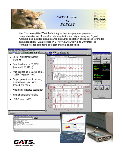
计算机辅助测试套件信号分析软件说明书
The Computer-Aided Test Suite™Signal Analysis program provides a comprehensive set of tools for data acquisition and signal analysis. Signal Analysis also includes signal source output for excitation of structures for modal data acquisition. Data storage in STAR™, MATLAB™, and Universal FileFormat provides extensive post test analysis capabilities.•Up to 4 simultaneous inputchannels•Sample rates up to 51,200Hz(bandwidth 20,000Hz)•Frames sizes up to 32,768 points(12,800 frequency lines)•Output generator with random,burst random, sine, userdefined, and chirp•Free run or triggered acquisition•Input channel auto-ranging•USB Connect to PCCATS AnalysisforBOBCATBOBCAT Signal Analysis Technical SpecificationsSpectral Dynamics, Inc. 2730 Orchard Parkway San Jose, CA 95134 TEL. 408.678.3500 FAX. 408.678.3580 In keeping with our commitment to continuous product improvement, the information herein is subject to change. Copyright 2008 Spectral Dynamics, Inc. All rights reserved. CATS and STAR logos are registered trademarks or Spectral Dynamics Inc. All other trademarks are properties of their respective owners.TSBOBCAT03/08InputInput channels 4: all simultaneously sampledInput dynamic range >92 dBMaximum input ±10VVoltage ranges 27 mV to 10V full scale, 3dB stepsOverload detection Full scale on all channels, analog and digital detection Voltage coupling AC or DCICP power 4mA (20V maximum into open circuit)Maximum rated input signal ±35 Volts peakSampling rate 51,200 samples per secondFrame size 512, 1024, 2048, 4096, 8192. 16384, 32768 Samples Frame duration 10ms to 256 secondsOutputOutput channels 1Output dynamic range >90 dBMaximum output amplitude ± 12V peakMaximum output current 16mAVoltage range attenuator Programmable 48-bitAttenuator range 0 to -160dBSampling rate 51,200 samples per secondDrive signalsRandom Broadband; up to 3 VrmsSine 1 to 10000Hz; up to 10 VpeakPseudo random Broadband; up to 3 VrmsSine chirp Fast sine sweepBurst random Windowed random burst with variable durationUser-defined User-defined shaped broadband outputAnalysisFrequency range (DC to) 50, 100, 200, 500, 1000, 2000, 5000, 10000 and20000 HzFrequency resolution 200, 400, 800, 1600, 3200, 6400 and 12800 lines FFT windows Uniform, Hanning, Blackman, Calibration,Force/impact, Hamming, Blackman-harris andCorrelationWindow Scaling Broadband or NarrowbandSpectra Weighting Flat (None), A , B ,C acoustic functions AveragingTypes Linear, exponential, peak hold (max)Number 1 to 32,768Overlap Processing None, 25%, 50%, 75%, Max.TriggeringModes Free run, automatic, manualSource Any Input channelThreshold ±mV, ± percent of full scaleSlope Rising/failingDelay Specified in ms or percent of framePre/Post-trigger duration Specified in msChannel SetupChannel type Measurement, Reference, Measurement, inactive Sensitivity 0.001 to 1,000,000 mV/EUICP power On/offCoupling AC or DCChannel label Up to 8 characters for each channelTransducer serial number Up to 10 characters for each channel; DB optional EU DefinitionsBase Engineering Units Label(EU), Conversion(EU/Transducer Units)EU Calculations and Support Integrated (Label and Scale Factor), Double Integrated(Label and Scale Factor), Differentiated (Label and Scale Factor), Double Differentiated (Label and Scale Factor)On-Line ControlsStart/Stop test Initiates or stops data acquisitionAuto-range Automatically set Input channel voltage ranges Manual Trigger Set trigger to Manual arm modeArm Trigger Initiate trigger threshold detectionOutput Turn output drive signal on/offOn-Line Status MonitorsAverage count Current number of frames averaged Channel Status RMS or peak levels for all active channels Message log Records all test operations, including operatorcommands, and reports on any error conditions On-Line AnalysisReal-time displays Any available function for all available channels maybe displayed simultaneously.Functions analyzed duringthe testTime Windowedandun-windowed; OrbitAuto spectra Linear, Magnitude Squared, PSDCrossspectra Magnitude, phase, real, ImaginaryTransfer functions Magnitude, phase, real, Imaginary, coherence; Bode Statisticalfunctions Probability density, auto correlation, cross correlation 1/n Octave 1/1, 1/3, 1/6, 1/12, 1/24Real-time/Stored data Simultaneous display and overlay of spectra or timehistories for real-time data and any stored data Modal Data AcquisitionModal DOF Data stored and recalled according to modal DOF label Auto increment Automatic incrementing of modal DOF duringacquisition. Acquisition can be linked to Modal ModelvisualizationDOF Table Set up multiple tables of DOF numbers and directionsfor efficient management of modal dataData storage format CATS binary format, STAR binary, and Universal FileFormatTransient AnalysisFrequency range (DC to)25Hz to 10kHz; dependent on pulse duration and over-sample ratio. 20KHz optionalFunctions Acceleration, Velocity, Displacement, SRS (Primary+,Primary-, Maxi-max)Frame size Automatic selection of 512 – 32,768 samples, inpowers of 2 stepsReference profile User-defined SRS referenceData StorageFormat Spectral Dynamics binary or Universal File Format Setup options Select from all available functions, new data file orappend data to filePlayback Automatic play of entire test data file, with adjustabledisplay update delay; manual selection; select by inputchannel number.Run message log Text file records all system status messages displayedduring test runExport Manager (Optional)File formats ASCII, STAR™, I-DEAS™, MATLAB™, UFF, ZMOD,ROM, SIR-1000, TH, TIM, TPD, TRD。
- 1、下载文档前请自行甄别文档内容的完整性,平台不提供额外的编辑、内容补充、找答案等附加服务。
- 2、"仅部分预览"的文档,不可在线预览部分如存在完整性等问题,可反馈申请退款(可完整预览的文档不适用该条件!)。
- 3、如文档侵犯您的权益,请联系客服反馈,我们会尽快为您处理(人工客服工作时间:9:00-18:30)。
TestToolsV5.0帮助文档光猫测试维护工具说明书mervyn2014-3-29目录一、TestToolsV5.0程序概述: (2)二、TestToolsV5.0程序的运行及配置步骤: (2)三、TestToolsV5.0功能模块介绍: (4)(一)TestToolsV5.0初始化配置: (4)(二)设备登陆信息配置: (5)(三)更新IP地址及重置IP地址功能: (6)(四)设备配置管理功能: (7)4.1查看Telecomadmin密码 (7)4.2查询地区码: (7)4.3查询设备软件版本 (8)4.4查询设备硬件版本 (8)4.5重置telecomadmin密码: (8)4.6修改超级用户名: (9)4.7修改地区码: (10)4.8初始化F460C220配置 (12)4.9软重置设备 (12)4.10打开Web配置及打开Web_shell_cmd配置 (12)(五)设备MAC地址管理 (12)5.1 清空MAC地址(请慎用) (12)5.2 MAC地址管理 (13)5.3 点亮及熄灭所有的灯 (13)(六)光猫设备端口管理 (14)6.1 Telnet端口管理 (14)6.2 批量尝试开启Telnet端口 (14)6.3自定义尝试批量开启Telnet端口 (15)6.4关闭Telnet23端口 (15)6.4关闭80端口 (15)(七)光猫文件配置 (15)7.1 添加、建立、删除web_shell_cmd.gch文件 (15)(八)测试数据核对 (16)8.1 ECC上传数据核对 (16)8.2 生成测试报表 (18)8.3 备份数据库 (19)(九)帮助 (20)9.1 技术支持 (20)9.2意见反馈 (21)9.3关于TestTools (21)四、程序使用声明 (22)一、TestToolsV5.0程序概述:TestTools V5.0程序的主要功能是集成了对光猫的测试所使用到的一些测试脚本功能,并加入了连通测试的功能,测试序列号比对及生成测试文档的功能,可以在测试的过程中查询某个串号是否已经上传到服务器等功能,方便测试工作的开展。
二、TestToolsV5.0程序的运行及配置步骤:TestTools V5.0是通过JDK程序进行编写,需要安装JRE6.0的程序运行环境,操作系统要求为:Windows XP SP3及以上,内存要求大于512MB。
程序运行的主界面如下:首先对程序的运行环境进行配置,需要搭建有jre的运行环境,程序才可以正常运行,下载安装jdk1.6.0_21或者JRE6,jdk1.6.0_21下载地址为:/xy3/jdk6.zip,下载解压进行安装,并且记住程序的安装目录,在安装文件夹中找到jdk文件的bin文件夹,然后在“我的电脑”→右键“属性”→“高级”→“环境变量”→“系统变量”中找到Path这个变量,将jdk的bin文件夹的路径添加到这个环境变量中,添加的方法:将鼠标定位到这个环境变量值的最前面,将bin路径复制粘贴进去,然后在后面加入一个英文状态下的“;”,添加的路径如:“C:\Java\jdk1.6.0_21\bin;”(不含双引号)。
然后点击确定退出配置。
即可完成系统的环境配置。
程序直接可以通过双击的方式进行运行,但是部分计算机无法运行的情况下,可以在TestToolsV5.0程序的目录下面添加一个批处理文件,在里面添加如下的内容:start javaw -jar TestTools(Version5.0).jar,保存后,直接双击这个批处理文件即可运行程序。
三、TestToolsV5.0功能模块介绍:(一)TestToolsV5.0初始化配置:TestToolsV5.0运行后,需要读取程序目录下面的ProgramConfigFile.ini文件进行程序的初始化配置。
配置如下图:其中Batch open Telnet port IP:是配置批量开启Telnet端口的IP段;Local connectivity test IP address:是配置本地IP地址测试的IP段;Remote connectivity test IP address:是配置远程IP地址测试的IP段;The localdatabase path:是配置本地数据库的路径;The local backup database path:是配置本地数据库备份的数据库的路径;Remote database path:是配置远程数据库的路径的配置。
用户可直接通过编辑程序目录下面的ProgramConfigFile.ini配置系统,配置完成后,再重新启动系统后,配置完成;或者通过系统下面的“数据库配置”来完成系统配置,修改完成后,点击修改完成系统的配置,如果发现程序无法正常运行,可通过该界面的初始化配置完成对程序的初始化设置即可。
读取SetPort.ini文件进行批量端口初始化配置,该文件路径为程序的安装目录,按一个端口一行进行配置,目前只提供直接修改文件进行配置。
(二)设备登陆信息配置:通过主界面左下角的“配置设备登陆信息”按钮,打开设备登录信息配置功能,默认登录信息为:IP地址:192.168.1.1,用户名:root,密码:Zte521,端口:23. 如图:在使用过程中,根据登陆设备的不同,按需要对该信息进行修改,修改完成后点击“保存设备登录信息”即可。
(三)更新IP地址及重置IP地址功能:这两个功能主要是通过手工配置了SetIPConfig.ini 文件,后更新到程序中使用的借口,点击后会根据文件的配置内容,更新测试连通性的IP地址。
(两个功能的区别:重置IP地址功能会将程序配置的IP地址初始化为:192.168.1.1,192.168.1.206)。
重置IP地址的提示如图:(四)设备配置管理功能:该功能会实现对设备的基础信息的查询及修改功能,主要承担的功能为:4.1查看Telecomadmin密码程序直接返回telecomadmin的密码,同时对密码做出比对,具体结果如下:如果密码不正确,会出现如下的提示:4.2查询地区码:程序直接返回设备的地区码,具体结果如下(224的地区码代表是广西,如果是其他代码,需要使用修改地区码进行修改):4.3查询设备软件版本程序直接返回设备的软件版本代码,具体结果如下:4.4查询设备硬件版本程序直接返回设备的硬件版本代码,具体结果如下:4.5重置telecomadmin密码:如果发现提示telecomadmin密码错误,或者是使用telecomadmin登陆网页,提示密码错误,就使用该功能进行密码的重置,将密码恢复到原始状态即可。
返回结果如下:有时候会出现如下提示:4.6修改超级用户名:根据平时的检测发现,部分用户在使用设备后,会将设备的超级用户名修改成其他的名称,这个使用就需要使用该功能进行修改,点击“修改超级用户名”后会提示输入需要修改的用户名,默认不输入的情况下,会将用户名改为“telecomadmin”,也可以根据自己的个性化需要修改成其他的用户名,但是修改成其他的用户名后,登陆网页的用户名也需要进行相应的调整,具体如下:直接点击“确定”按钮,弹出如下提示:点击“确定”返回的结果如下:4.7修改地区码:检测过程中,发现设备的地区码不是224或者为0(0代表是通用的地区码),就可以使用该功能进行地区码的修改,点击“修改地区码”命令后,会弹出需要输入的地区码代码,默认不输入的情况下会将地区码改写为224,(系统会先查询设备的地区码,如发现修改的地区码与设备中的地区码一致,会弹出警告,同时终止地区码修改的操作。
),操作如图:以上是地区码相同的情况下的提示,地区码不同的情况下如图:点击“确定”后,设备进入重新启动的过程中,重启完成后,设备的地区码即可完成修改。
4.8初始化F460C220配置该功能主要是针对旧款的F460C220的程序,主要使用的命令为:loaddefaultconfig,为设备进行重置。
同时使用该功能的时候,需要修改设备的登录信息方可使用。
4.9软重置设备该功能主要使用sendcms 1 DB Reset命令对设备进行重置。
4.10打开Web配置及打开Web_shell_cmd配置该功能主要是快捷打开http://192.168.1.1(该网址为光猫设备的Web配置路径!)及http://192.168.1.1/web_shell_cmd.gch(该网址必须是光猫中存在配置文件web_shell_cmd.gch才可以打开,打开这个配置后,直接可以不用登陆密码进入修改光猫的配置)。
(五)设备MAC地址管理5.1 清空MAC地址(请慎用)该功能主要是完成对可以进入Telnet的设备进行MAC 地址的情况,将MAC地址(256)进行复位(复位后的MAC 地址为:00:00:00:00:00:00),复位后,设备将无法ping 通192.168.1.1,必须通过串口进入设备进行重写。
(为避免用户进行误操作,在系统组界面设计了一个的选项,默认情况下是处于选中状态,如果需要使用该功能,必须将这个选项取消。
)5.2 MAC地址管理该功能可以完成对设备的MAC的查询及修改功能,提供逐个的MAC地址查询,将查询到的MAC地址进行显示,并提供MAC地址的修复功能,对某些MAC为空的设备,全部将5个MAC地址写入光猫。
(5个MAC地址以256这个光猫的MAC地址为参照值,如果256的MAC地址为空,那将无法修改。
)5.3 点亮及熄灭所有的灯该功能主要是提供给用户对设备的灯的检测手段,如果选中点亮的情况下,除了网口灯不亮,其他等必须全部亮,否则为故障设备。
(六)光猫设备端口管理6.1 Telnet端口管理主界面如上,该程序会批量通过对右侧的端口逐个尝试打开Telnet的端口配置,用户可以通过左侧的IP地址列表选择设备的IP地址,然后进行操作,直接点击左侧的IP,然后将IP转移到中间的输入框,点击执行即可。
IP地址段可以通过ProgramConfigFile.ini完成,端口可以通过SetPort.ini文件完成。
配置SetPort.ini文件完成后,通过界面上面的加载端口对文件进行重新加载,添加的端口号就会出现在端口列表。
必要情况下,可以通过初始化端口配置,恢复设备的初始端口配置。
6.2 批量尝试开启Telnet端口该功能与前面的功能重复,但是该功能仅提供对192.168.1.1的IP段的设备进行尝试开启。
6.3自定义尝试批量开启Telnet端口该功能与6.1的功能重复,但是该功能仅提供对固定的端口进行开启,增加功能是用户可以自定义IP地址。
6.4关闭Telnet23端口该功能是提供关闭设备的23号端口,关闭后,设备将无法通过Telnet功能进入设备进行配置。
