巨鲨显示器120202
VG2791R 系列 液晶显示器 用户指南说明书

ii版权所有© 2020 ASUSTeK COMPUTER INC.保留所有权利。
除了购买者出于备份目的而保留的文档外,未经 ASUSTeK COMPUTER INC.(以下简称“ASUS ”)明确书面许可,不得以任何形式或通过任何方式复制、传播、转录本手册的任何部分,包括其中介绍的产品和软件,也不得将其存储到检索系统中或翻译成任何语言。
(“ASUS ”)在下列情况下,不能享受产品保修或维修服务:(1) 未获得ASUS 书面授权,而修理、修改或改动产品;(2) 产品序列号损毁或缺失。
ASUS “按原样”提供本手册,不提供任何明示或隐含的担保,包括但不限于对于适销性或针对特定目的的适用性的隐含担保或条件。
无论在任何情况下,ASUS 及其董事成员、高级职员、员工或代理不对由于本手册或产品中存在任何缺陷或错误而导致的任何间接、特殊、偶然或必然损失(包括收益损失、业务损失、不能使用或数据丢失、业务中断等)承担任何责任,即使 ASUS 已被告知此类损失的可能性。
本手册中包含的规格和信息仅供一般性参考,可能会随时变更而不另行通知,因此不应构成 ASUS 的承诺。
ASUS 对本手册(包括其中介绍的产品和软件)中可能存在的任何错误不承担任何责任。
本手册中出现的产品名称和公司名称可能分别是或不是相应公司的注册商标或版权,仅用于标示或解释目的,无意侵犯其所有者的权益。
声明.........................................................................................................iii 保养和清洁. (iv)1.1欢迎使用! .....................................................................................1-11.2物品清单.........................................................................................1-11.3组装显示器 .....................................................................................1-21.4外形尺寸.........................................................................................1-21.5连接线缆.........................................................................................1-31.5.1 液晶显示器后部 ...............................................................1-31.6显示器简介 .....................................................................................1-41.6.1 使用控制按钮 .................................................................1-42.1卸下底座 ......................................................................................... 2-12.2 调整显示器 .....................................................................................2-23.1 OSD (屏幕显示)菜单...................................................................3-13.1.1 如何重新配置 ..................................................................3-13.1.2 OSD 功能介绍 .................................................................3-23.2规格 ..............................................................................................3-113.3故障排除(常见问题) .................................................................3-123.4 支持的时序列表 ............................................................................3-13iii联邦通信委员会声明本设备符合 FCC 规则第 15 部分的要求。
VS222HD4K 2x2 HDMI 矩阵开关-4K 快速切换和自动感知产品说明书

2x2 HDMI Matrix Switch - 4K with Fast Switching and Auto-SensingProduct ID: VS222HD4KSave time and hassle by automatically switching between your HDMI audio/video sources. This 2x2 HDMI® matrix switcher provides the ultimate viewing experience, with support for Ultra HD 4K. It lets you connect two HDMI sources to two HDMI displays, with exceptional 4K resolution, while switching seamlessly between your video sources.Impressive image quality with 4K supportThe matrix switch supports Ultra HD 4K picture quality on two monitors while switching between content from HDMI source devices - including Blu-ray™ players or DVD players, computer systems, video game consoles, digital cable or satellite boxes, and A/V receivers.4K support ensures a higher level of image clarity and visibility, delivering four times the resolution of 1080p - 8.29 million pixels versus 2.07 million pixels. It provides a more engaging visual experience for audiences in a wide range of venues including conference centers, boardrooms, educational facilities, and commercial settings. With its exceptional image quality, 4K resolution is also ideal for bringing your digital signage to life.Fast and versatile switching optionsEnjoy hassle-free operation with four different switching modes:•Matrix switching: lets you route either HDMI source (Input 1 or Input 2) to either monitor (Output 1 and/or Output 2) - and independently switch two displays between two video sources.•Fast auto-switching: ensures minimal time for switching between HDMI sources. The switch provides effortless operation with advanced auto-sensing - it detects the latest connected HDMI source andautomatically switches both outputs to that device. It also ensures no downtime in a digital signageapplication if a source signal is accidentally powered off or fails.•Priority switching: identifies the first port to have first priority for HDMI sources, which will be output on both displays.•Manual switching: enables you to manually select your HDMI source with front-panel buttons that are easy to use.An IR remote control is included in the box, enabling you to select your desired input source remotely. The RS-232 serial control interface ensures easy remote operation with serial control enabled devices.Hassle-free setup with plug-and-play installationThe matrix switch is easy to install. EDID emulation saves you time during setup by ensuring all of your display settings, such as native resolution and refresh rate, are communicated between your display and video source devices. The built-in EDID copy feature maximizes compatibility with your 4K display, to ensure a convenient plug-and-play installation and the sharpest image quality.The VS222HD4K is TAA compliant and backed by a 2-year warranty with free lifetime technical support.Certifications, Reports and Compatibility Applications•Run Ultra HD 4K multimedia presentations on two monitors inconference rooms, commercial settings or at trade shows•Switch between different video sources on your digital signage displays in hospitals, shopping centers, or schools•Connect and switch between two video sources and two displays on a test bench, for troubleshooting computers•Automatically switch between your Blu-ray player, set-top box, or gaming console in a home theatre environmentFeatures•Impressive image quality with support for Ultra HD 4K•Easy operation with automatic, priority and manual switching between HDMI sources•Access two HDMI source devices on two independent HDMI displays,with 2 x 2 matrix switching•IR remote control included•RS-232 serial control interface•EDID copy support ensures accurate display output•Backward compatible with high-definition 1080p•Mounting hardware includedWarranty 2 YearsHardware Audio YesAV Input HDMIAV Output HDMIIndustry Standards HDMI 1.4Ports2Performance Audio Specifications7.1 Surround soundMax Distance10 m / 33 ftMaximum Cable Length393.7 in [10000 mm]Maximum Digital Resolutions4K @ 30 HzSupported Resolutions3840x2160 (4K)2560x16001920x12001920x1080 (1080p)1280x720 (720p)Wide Screen Supported YesConnector(s)Connector A 2 - HDMI (19 pin) FemaleConnector B 2 - HDMI (19 pin) Female1 - RJ-11 FemaleIndicators LED Indicators 2 - Active port LED1 - Power LEDPower Input Voltage100 - 240 ACOutput Current 1.5Output Voltage12 DCPower Consumption (In Watts)18Power Source AC Adapter Included Environmental Humidity0% ~ 80%Operating Temperature0°C to 50°C (32°F to 122°F)Storage Temperature-20°C to 70°C (-4°F to 158°F)Color BlackPhysicalCharacteristicsProduct Height0.8 in [2 cm]Product Length 6.1 in [15.6 cm]Product Width 2.6 in [65 mm]Weight of Product10.4 oz [296 g]Package Height 2.6 in [65 mm]PackagingInformationPackage Length 6.1 in [15.6 cm]Package Width9.3 in [23.5 cm]Shipping (Package) Weight29.7 oz [841 g]What's in the Box Included in Package 1 - 2x2 HDMI matrix switch1 - remote control1 - universal power adapter (NA/EU/UK/AU)1 - RJ11 cable (1200mm)1 - RJ11 to DB-9 serial adapter1 - mounting kit1 - quick start guideProduct appearance and specifications are subject to change without notice.。
巨鲨显示器(带讲解文稿)

衰减极慢,图像显示结果长时间保持一致性 诊断结果更准确
Medical Display Expert 巨鲨 专业显示器
40.
CT、磁共振专用双屏
最新科技创新之举---在一台显示器上实现双屏的应用
CT、磁共振专用?
Medical Display Expert 巨鲨 专业显示器
3M/2M/1M彩色专业显示器
CT、磁共振专用双屏
9M彩色专业显示器
4M彩色专业显示器
Medical Display Expert 巨鲨 专业显示器
17.
临床浏览系列
—— 全面医疗显示解决方案
1M彩色专业显示器
1M单色专业显示器
2M彩色专业显示器
2M单色专业显示器
Medical Display Expert 巨鲨 专业显示器
Medical Display Expert 巨鲨 专业显示器
11.
Gray Scale Terminology
医用10bit以上灰阶
民用8bit灰阶
Medical Display Expert 巨鲨 专业显示器
为了作出准确的诊断,要求医用显示器实行10bit以上灰阶。
12.
DICOM 3.0
Ins-guard是一套亮度实时监测和自动反馈控制系统,自动保证液晶面上每个像素点的亮 度输出都符合DICOM/DIN6868-57标准,使用过程中不再需要繁琐的手工校正。
校正器相对亮度值测量技术(比一些厂商的亮度绝对值测量 技术更准确),亮度响应更精确、亮度调节更方便;
原厂设置
DICOM 700 DICOM 650 DICOM 600 DICOM 550 DICOM 500 DICOM 450 DICOM 400 DICOM 350
HP 2310e和2310ei LCD 显示器 说明书

用户指南©2010Hewlett-Packard Development Company,L.P.Microsoft、Windows 和 Windows Vista 是Microsoft Corporation 在美国和/或其他国家的商标或注册商标。
HP 产品和服务的所有保修限于这些产品与服务所附带的明确保修声明。
本文的任何条款都不应视作构成保修声明的附加条款。
HP 不对本文的技术性错误、编印错误或疏漏承担任何责任。
本文档包含的所有权信息受版权保护。
未经Hewlett-Packard Company 事先书面许可,不得将本文档的任何部分影印、复制或翻译成其他语言。
第一版(2010 年 4 月)文档部件号: 610261-AA1关于本指南本指南提供与安装显示器、安装驱动程序、使用屏幕显示菜单、故障排除和技术规范有关的信息。
警告!此格式的文字表示:如果不按照指示操作可能导致人身伤害,甚至死亡。
注意:此格式的文字表示:如果不按照指示操作可能致使设备损坏或信息丢失。
注:此格式的文字提供重要的附加信息。
ZHCN iiiiv 关于本指南ZHCN目录1 产品特性 (1)HP2310e/2310ei LCD 显示器 (1)2 安全和维护准则 (3)重要安全信息 (3)安全预防措施 (3)维护准则 (4)清洁显示器 (4)装运显示器 (4)3 安装显示器 (6)打开显示器包装 (6)装配显示器 (6)连接显示器电缆 (7)连接 DVI-D 视频电缆 (7)正在连接 DisplayPort 视频线 (8)连接 HDMI 电缆(仅适用于 2310e 型号) (8)连接电源线 (9)高带宽数字内容保护 (HDCP) (9)打开显示器 (9)选择视频输入接口 (10)调整显示器的倾斜角度 (10)调整扭转角度 (11)4 操作显示器 (12)CD 软件和实用程序 (12)安装驱动程序 (12)前面板控制按钮 (12)使用屏幕显示 (OSD) (13)识别显示器状况 (17)省电功能 (17)附录 A 故障排除 (18)解决常见问题 (18)从 获取支持 (19)准备致电技术支持 (19)查找额定值标签 (19)ZHCN v附录 B 技术规格 (20)HP LCD 显示器 (20)预设视频模式 (20)进入用户模式 (21)LCD 显示器质量和像素策略 (21)附录 C 机构规定注意事项 (23)(美国)联邦通信委员会注意事项 (23)修改 (23)电缆 (23)标有 FCC 徽标的产品的一致性声明(仅适用于美国) (23)适用于加拿大的注意事项 (24)Avis Canadien (24)欧盟规程通告 (24)德国人机工程学通告 (24)适用于日本的注意事项 (25)适用于韩国的注意事项 (25)电源线配件要求 (25)适用于日本的电源线要求 (25)产品环境注意事项 (25)ENERGY STAR® 资格 (25)日常处理废旧器件的注意事项(适用于欧盟) (26)化学物质 (26)HP 回收办法 (26)有害物质的限制 (RoHS) (26)土耳其 EEE 法规 (27)vi ZHCN1产品特性HP2310e/2310ei LCD 显示器图 1-1HP2310e/2310ei LCD 显示器HP2310e/2310ei LCD(液晶显示)显示器采用具备有源矩阵和下列特性的带白色 LED 背光薄膜晶体管 (TFT) 屏幕:●大尺寸屏幕●最大图像分辨率: 1920x1080@60 赫兹,且支持较低分辨率的全屏显示●DisplayPort 数字输入信号●提供单连接 DVI-D 到 DVI-D 电缆的 DVI 数字输入信号●高清晰度多媒体接口 (HDMI)(只适用于 2310e 型号) 信号输出●反应迅捷,玩核心游戏和图形制作时可获得更佳效果●视角宽广,无论是坐着、站着还是从显示器的两侧,均易于观看●动态对比度,提供更深的黑度和更亮的白度以实现出众的色差效果,令玩游戏和观看电影更具特色●倾斜度调整●扭转角度调整●即插即用功能(如果您的计算机系统支持此功能)●屏幕显示 (OSD) 可调,便于设置和优化屏幕(可选择英文、简体中文、繁体中文、法文、德文、意大利文、西班牙文、荷兰文、日文或巴西葡萄牙文)●节能装置,有助于减少能源消耗●“快速查看”设置显示ZHCN HP2310e/2310ei LCD 显示器1●DVI、HDMI 和 DisplayPort 输入具备高带宽数字内容保护 (HDCP)●软件和实用程序 CD,其中包含以下内容:◦驱动程序◦相关文档2第 1 章 产品特性ZHCN2安全和维护准则重要安全信息本显示器已附带电源线。
MOXA MD-200系列海洋显示器系列说明书

P/N: 1802002260012 *1802002260012*MD-200 SeriesQuick Installation GuideVersion 2.1, January 2021Technical Support Contact Information/support2021 Moxa Inc. All rights reserved.OverviewThe MD-200 marine display series is designed for durably reliable service as an ECDIS display component. The MD-200 series offers full range dimming and optional optical bonding, making it well-suited not only for ECDIS applications, but also for a variety of other bridge applications. The MD-200 series features both AC and DC power inputs, and can be conveniently installed on any bridge, without the need for extra hardware.Moxa’s marine displays are compliant with the most important industrial marine standards, including IEC 60945, DNV, and IACS-E10, giving strong assurance of their suitability for marine applications.The following lists the models in the MD-200 series:•MD-226X: 26-inch display with 16:10 aspect ratio.•MD-224X/MD-224Z: 24-inch display with 16:9 aspect ratio.•MD-219X/MD-219Z: 19-inch display with 5:4 aspect ratio. Package ChecklistBefore installing the MD-200 series, verify that the package contains the following items:•MD-200 series display•VGA cable•DVI-D cable•2-pin terminal block x 1•5-pin terminal block x 2•Quick installation guide (printed)•Warranty cardNOTE: Please notify your sales representative if any of the above items are missing or damaged.Hardware InstallationAppearanceMD-226/224MD-219SavvyTouch Display Control ButtonsThe following table describes the SavvyTouch display controls on the front surface of the MD-200 series. These intelligent controls will light up with a simple wave of your hand over the area of the screen where they are located.NameDisplayColorControl Function/Color LegendMenu/PowerGreen Display is powered on and functioningnormally. Touch the button to show theOSD settings menuRed No input signal detected. Display standby Off Power is down and the display is offBrightness White +: To increase brightness of panel -: To decrease brightness of panelInfoOffAC/DC power is functioning normallyDisplay modeWhiteSwitch between DAY/DUSK/NIGHTbrightness modesOff Panel brightness out of default rangeInstalling the MD-200 SeriesDesktopThe MD-200 series comes with optional brackets that allow you to installthe display on a horizontal surface, such as a desktop. Three round screws are required for each bracket. See the figure for detailed screw specifications and their torque values.Place your MD-200 series display on a clean, flat, well-ventilated desktop. To protect the computer from overheating, leave some ventilation space between the MD-200 series and other equipment.Do NOT place equipment or objects on the panel, as this might damage internal components.Panel MountingThe MD-200 series comes with 14 optional clamp mounts for installation on a wall (where space has been cut out to accommodate the rest of the hardware) or into computing stations where a flush mount is desired. The maximum thickness of the surface to which the computer can be clamped is 11 mm. For a secure mounting, all 14 clamps must be used.The clamp arms are fastened into slots on all four sides of the MD-200 series. Use the short M4 SUS screws to fasten the clamp arms to the MD-200 series mounting slots, as shown in the following magnified inset in the diagram. Next, use the clamps to fasten the MD-200 series to its mounting point; please note the torque value as shown in the figure.VESA MountingThe MD-200 series also comes with an optional VESA mounting kit. Six flat screws and four round screws are required to fasten the VESA mounting bracket. See the following figure for detailed screw specifications and torque values.An additional four screws (not included in the kit) are required to mount the display on a VESA rack. For this purpose, use M6 screws that are between 10 and 12 mm in length.Connector DescriptionExtending the DisplayThe MD-200 series comes with both standard VGA and DVI-D interfaces on the bottom panel. It automatically detects whether the input video source is from the VGA or DVI-D interface. Configuring the Display via the Serial PortThe MD-200 series has two serial ports. The RS-232 port uses a DB9 connector, and the RS-422/485 port uses a terminal block connector. Either serial port can be used to modify the display parameters using UART commands. For information on serial port configuration, see the MD-200 Series Hardware Manual.The pin assignments for the ports are shown in the following table: Pin RS-232 1 DCD 2 RxD 3 TxD 4 DTR 5 GND 6 DSR 7 RTS 8CTSRS-422/485 (Terminal Block) PinoutsPin RS-422 RS-485 (4-wire) RS-485 (2-wire)1 RxDB(+) RxDB(+) –2 RxDA(-) RxDA(-) –3 TxDB(+) TxDB(+) DataB(+)4 TxDA(-) TxDA(-) DataA(-) 5GNDGNDGNDPowering on/off the MD-200 SeriesTo power on the MD-200 series, connect the unit to an AC power source, a DC power source, or both. Touch the MENU button for 1 second to turn on the display. Touch the MENU button for 4 seconds to turn off the display.Grounding the MD-200 SeriesProper grounding and wire routing help to limit the effects of noise from electromagnetic interference (EMI). Run the ground connection from the ground screw to the grounding surface prior to connecting the power source.For detailed configuration of the MD-200 Series, refer to the MD-200 Series Hardware Manual.。
TELEMEVANIQUE Magelis XBT OT 说明书

Magelis XBT OT 用户手册35015239 00简体中文35015239 00感谢您购买施耐德OPTI XBT OT系列可编程人界面产品(以下简称为“OT 单元”)。
操作OT单元之前,请确保阅读本手册,以便熟悉OT单元的操作步骤和功能。
注意1.未经施耐德电气公司许可,禁止完全或部分复制本手册的内容。
2.本手册提供的信息如有变更,恕不另行通知。
3.如您发现任何遗漏或错误,恳请联系施耐德电气公司。
4.施耐德电气对用户使用该产品所引起的伤害、损失以及所引发的第三方责任,本公司概不承担,敬请谅解。
2007 Copyright Schneider Electric.版权所有。
本手册中使用的产品名称都是相关公司商标/注册商标。
箱单安全须知 (3)信息符号 (4)LCD面板的操作 (5)XBT OT系列的机型和功能 (6)装箱单 (7)UL/c-UL 认证 (8)CE 认证 (9)章 1概述1.1系统设计.........................................................................................................1-21.2附件.................................................................................................................1-6章 2部件名称及功能2.1XBT OT 2110/2210 系列.................................................................................2-22.2XBT OT 4320 系列..........................................................................................2-32.3XBT OT 5220/5320 系列.................................................................................2-5章 3规格3.1XBT OT 2110/2210 系列.................................................................................3-23.1.1 一般规格...............................................................................................................3-23.1.2 性能规格...............................................................................................................3-43.1.3 接口规格...............................................................................................................3-63.1.4 外形尺寸...............................................................................................................3-93.2XBT OT 4320 系列........................................................................................3-123.2.1 一般规格.............................................................................................................3-123.2.2 性能规格.............................................................................................................3-143.2.3 接口规格.............................................................................................................3-163.2.4 外形尺寸.............................................................................................................3-193.3XBT OT 5220/5320 系列...............................................................................3-223.3.1 一般规格.............................................................................................................3-223.3.2 性能规格.............................................................................................................3-243.3.3 接口规格.............................................................................................................3-263.3.4 外形尺寸.............................................................................................................3-291章 4安装与接线4.1安装.................................................................................................................4-24.2接线注意事项..................................................................................................4-74.2.1 连接电源线............................................................................................................4-74.2.2 连接电源..............................................................................................................4-124.2.3 接地.....................................................................................................................4-134.2.4 连接输入/输出信号线........................................................................................4-134.3插拔CF卡......................................................................................................4-144.3.1 插入CF卡..........................................................................................................4-154.3.2 拔出CF卡..........................................................................................................4-154.3.3 CF卡的使用.......................................................................................................4-154.4USB电缆夹具安装/拆卸...............................................................................4-164.4.1 XBT OT 2110/2210 系列....................................................................................4-174.4.2 XBT OT 4320 系列.............................................................................................4-184.4.3 XBT OT 5220/5320 系列....................................................................................4-19章 5维护5.1清洁显示器......................................................................................................5-25.2定期检查点......................................................................................................5-25.3更换安装衬垫..................................................................................................5-35.4更换背光灯......................................................................................................5-4 23安全须知请仔细阅读本说明手册,并且查看产品,以便在熟悉产品的情况下进行安装、操作及维护。
蔚蓝灯泡显示屏 Philips LED 80cm(31.5英寸) BDL3210Q 商品说明说明书

PhilipsLED Displayedge LEDHD ReadyBDL3210QEnjoy high performancewith this great value 31.5" signage displayDeliver startlingly clear images in a more eco-friendly way with the edge LED display. Highon performance and reliability, yet low on power consumption, it is ideal for projectswhere no compromise is accepted.Operational flexibility•Edge LED Backlight•USB Media Playback•Smart Control Software SuiteLower total cost of ownership•Power consumption below the industry averageOptimized for public viewing•WXGA,wide format 1366x768 resolution for sharper displaySustainable and safe•Complies with RoHS standards to care for the environment•3 year warrantyIssue date 2022-05-15Version: 15.3.112 NC: 8670 000 94246EAN: 87 12581 65762 8© 2022 Koninklijke Philips N.V.All Rights reserved.Specifications are subject to change without notice. Trademarks are the property of Koninklijke Philips N.V. or their respective SpecificationsLED Display80cm (31.5") edge LED, HD ReadyHighlightsEdge LED BacklightExperience an even dispersion of light with cutting edge LED technology. White LED's (light emitting diodes) are positioned around the rim of the panel to give a more even spread of light. This results in even lower power consumption, less heat to dissipate, and a true, uniform color range.Compliant with RoHS standardsPhilips designs and produces display products in compliance with strict Restriction of Hazardous Substances (RoHS) standards that restrict lead and other toxic substances that can harm the environment.WXGA 1366x768 resolutionWXGA,wide format 1366x768 resolution for sharper displayUSB PlaybackEnjoy your own media playback via the USB port. Simply plug in a USB drive, and create your own signage content to convey the marketing messages you want, when you want them. With a wide range of media formats supported, this powerful media player offers an excellent picture and true flexibility.Smart ControlControl and manage all of the signage displays on your network with this powerful software tool which allows you to change the settings of your display centrally via an RJ45 or RS232 connection. Smart Control allows you to set the video input, modify the color settings, set the display's ID when creating video walls and even diagnose each display's status, giving you all the power you need to manage your displays from one central location.3 year warrantyEnjoy peace of mind with our comprehensive 3 year warranty. With service centres around the globe, and our quick turnaround, you can be sure that in the most unlikely event of a display malfunctioning, we will find and fix the problem to your fullsatisfaction within the shortest period of time.Picture/Display•Diagonal screen size: 31.5 inch / 80 cm •Panel resolution: 1366 x 768p•Optimum resolution: 1366 x 768 @ 60 Hz •Brightness: 350 cd/m²•Contrast ratio (typical): 1200:1•Response time (typical): 8 ms •Aspect ratio: 16:9•Viewing angle (H / V): 178 / 178 degree •Pixel pitch: 0.17 x 0.51 mm •Display colors: 16.7 Million•Picture enhancement: 3/2 - 2/2 motion pull down, 3D Combfilter, Motion compens. deinterlacing, Progressive scan, 3D MA deinterlacing, Dynamic contrast enhancementSupported Display Resolution•Computer formats Resolution Refresh rate 640 x 480 60, 67, 72, 75Hz 800 x 600 56, 60, 72, 75Hz 1024 x 768 60Hz 1280 x 768 60Hz 1280 x 800 60Hz 1360 x 768 60Hz 1366 x 768 60Hz 1440 x 900 60Hz 1920 x 1080 60Hz •Video formats Resolution Refresh rate 480i 60Hz 480p 60Hz 576p 50Hz 576i 50Hz 720p 50, 60Hz 1080i 50, 60Hz 1080p 50, 60HzConnectivity•PC: VGA-in D-Sub 15HD, RS232 D-Sub9, 3.5 mm PC audio input x1•AV input: HDMI x2, Audio (L/R) x2, Composite RCA x2•Other connections: Component RCA x1•USB: USB 2.0 x 2•AV output: SPDIF Out, Composite RCA x1Convenience•Placement: Landscape•Screen saving functions: Pixel Shift, Low Brightness •Keyboard control: Hidden •Packaging: Reusable box•Network controllable: RS232Dimensions•Set dimensions (W x H x D): 745.2 x 462.7 x 56.8 mm•Bezel thickness: 22mm (45mm bottom)•VESA Mount: 200 x 100 mm •Set weight: 8.05 kg •Set weight (lb): 17.75 lbOperating conditions•Temperature range (operation): 0 - 40 °C•Relative humidity: 20-80 %•MTBF: 50,000 hour(s)Power•Consumption (On mode): 100W •Standby power consumption: <0.5WSound•Built-in speakers: 2 x 10W RMSAccessories•Included accessories: Remote Control, Batteries for remote control, AC Power Cord, VGA cable, User manual on CD-ROM, Quick start guide •Stand: BM03231 (Optional)Miscellaneous•Warranty: Global: 3 years•On-Screen Display Languages: English, French, German, Italian, Polish, Portuguese, Russian, Simplified Chinese, Spanish, Turkish•Regulatory approvals: CE, FCC, Class B, CCC, RoHS, UL/cUL, C-TickMultimedia Applications•Playback Formats: JPEG Still pictures, MP3, MPEG4, AAC LC, AC3, BMP Still pictures, GIF still pictures, M4A, MOV, PNG still pictures, RMVB (RealMedia var. bitrat), WMATechnical specifications•Backlight: Edge LED。
FLUKE Ti40 50 45 55 说明书

®Ti40, Ti45, Ti50, Ti55IR FlexCam Thermal Imager用户手册May 2006, Rev.1, 8/06 (Simplified Chinese)2006 Fluke Corporation, All rights reserved.All product names are trademarks of their respective companies.有限担保和有限责任Fluke 担保在正常使用和保养的情况下,其产品没有材料和工艺上的缺陷。
两年的担保期间由产品发货之日算起。
部件、产品修理和服务的担保期限为 90 天。
本担保仅限于Fluke 授权零售商的原购买人或最终用户,并且不适用于一次性电池、电缆接头、电缆绝缘转换接头或 Fluke 认为由于误用、改装、疏忽、污染及意外或异常操作或处理引起的任何产品损坏。
Fluke 担保软件能依照功能规格正常运行 90 天,并且软件是记录在无缺陷的媒介上。
Fluke 并不担保软件毫无错误或在运行中不会中断。
Fluke 授权的零售商应仅对最终用户就新的和未使用的产品提供本担保,但无权代表Fluke 公司提供额外或不同的担保。
只有通过 Fluke 授权的销售店购买的产品或者买方已经按适用的国际价格付款才能享受 Fluke 的担保支持。
在一国购买的产品需在他国修理时,Fluke 有权向买方要求负担重大修理/零件更换费用。
Fluke 的担保为有限责任,由 Fluke 决定是否退还购买金额、免费修理或更换在担保期间退还 Fluke 授权服务中心的故障产品。
如需要保修服务,请与您就近的 Fluke 授权服务中心联系,获得退还授权信息;然后将产品寄至服务中心,并附上产品问题描述,同时预付运费和保险费(目的地离岸价格)。
Fluke 不承担运送途中发生的损坏。
在保修之后,产品将被寄回给买方并提前支付运输费(目的地交货)。
BenQ 液晶显示器 说明书

将支撑底座的插口与支撑臂对准并与其保持平行,然 后将它们推压,直至锁定到位。
轻轻尝试将它们拉开以检查它们是否正确接合。
正视图 .................................................................................................................................... 6 后视图 .................................................................................................................................... 6 如何安装显示器硬件 ................................................................................................................... 7 如何分开支撑底座 ........................................................................................................... 11 充分利用 BenQ 显示器 .............................................................................................................. 12 如何在新电脑上安装显示器............................................................................................. 13 如何在现有的电脑上升级显示器 .................................................................................... 14 在 Windows Vista 系统上安装 .......................................................................................... 15 在 Windows XP 系统上安装.............................................................................................. 16 使用摄像头 (QEye)............................................................................................................. 17 拍摄静止图像或录制视频................................................................................................. 18 图像优化 ...................................................................................................................................... 21 如何调整显示器 .......................................................................................................................... 22 控制面板.............................................................................................................................. 22 热键模式.............................................................................................................................. 23 主菜单模式.......................................................................................................................... 24 故障排除 ...................................................................................................................................... 33 常见问题(FAQ).............................................................................................................. 33 是否需要更多帮助? ......................................................................................................... 34
大金鲨连线说明书
大金鲨连线说明书主机调整说明一、进入主机菜单方法:方法一:主机在运行的时候按一次《功能》键,主机屏幕最上面的一行显示“返回”,那么在主机和分机运行完这一圈,就可以进入主机菜单。
方法二:主机已经到了时间或者出现了故障,请先把主机电源关闭,然后一直按住《功能》键不放,把主机电源打开,就可以进入主机菜单。
二、主机查账方法:按住《功能》键不放进入主机菜单(参照进入主机菜单方法),然后按《移动》键,把箭头光标移到“查账”,按《确认》键,进入“查账”,按《移动》键,把箭头光标指到“主机”后,按《确认》键可以查主机的所有账目,按《确认》键可以翻页。
按《返回》键可以退出查账。
三、主机关键账目说明。
(主机的账目是所有分机加起来的整组机器的账目)总利润(总利润=总投币—总退币)总投币(总投币=上分+投币)总退币(总退币=下分+退币)上分(上分数据)下分(下分数据)投币(投币数据)退币(退币数据)四、主机报账方法:按住《功能》键不放进入主机菜单(参照进入主机菜单方法),然后按《移动》键,把箭头光标移到“报账”,按确认,进入报账。
第1页所有分机总的盈利(从上次归零算起),第2页当期所有分机实际利润(从上次打条码算起),第3页总的打了多少次条码,第4页机器的号码,第5页效验码,最后显示“请输入条码”,输入正确的条码后按《确认》键,就会显示报账成功。
五、主机时间挡机,延时方法:只要正确报账一次(请参照主机报账方法),输入正确的条码,就可以把时间重新延长5500分钟。
不管时间有没有到,任何时候都可以通过报账把时间延长到5500分钟。
六、主机归零方法:只要连续报账两次(请参照主机报账方法)就可以把主机归零。
下列几种情况主机必须归零:1:主机出现故障。
2:有新的分机要加入。
3:主机已经做到最高账目,显示08账目挡机。
4:主机的参数被调整过。
七、主机归零必须注意的事项:1:如果主机要归零,请把所有的分机全部打开,并且和主机正确连接。
巨鲨显示器

DICOM协议保证了 1. 图像的细腻性
- 展示更多的细节
2. 图像一致性 - 无论何时何地,图像显示一致性,保证诊断正确性
Medical Display Expert
巨鲨 专业显示器
28.
数字化诊断必须使用专业显示器!
分辨率 亮度 灰阶度 DICOM校正
Medical Display Expert
巨鲨 专业显示器
29.
巨鲨 全面医疗显示解决方案
JuSha Comprehensive Health Care Solutions
Medical Display Expert
巨鲨 专业显示器
30.
影像诊断系列
—— 全面医疗显示解决方案
5M/3M/2M/1M灰阶专业显示器
3M/2M/1M彩色专业显示器
常用民用显示器分辨率:1024x768, 1024x800, 1280x1024
Medical Display Expert
巨鲨 专业显示器
21.
Gray Scale Terminology 灰阶度
Medical Display Expert
巨鲨 专业显示器
22.
Luminance (brightness) 亮度
20.
Resolution 分辨率
1MP=1280x1024=1024x1280 2MP=1600x1200=1200x1600 3MP=2048x1536=1536x2048 4MP=2560x1600 5MP=2560x2048=2048x2560 9MP=3840x2400
C26=1920x1200 70寸=1920x1080
0
200
400
600
ICP DAS PCI-1202 1602 180x系列产品快速启动指南说明书

The package includes the following items:PEX-1202L/1202H, PCI-1202LU/1202HUPCI-1602U/1602FUPCI-1800LU/1800HU, PCI-1802LU/1802HUStep 1:Setup the Windows driver. The driver is located at: What’s in the shipping package?Installing Windows DriverThe PCI-1202/1602/180x series classic driver supports Windows 98/NT/2K and 32-bit XP/ 2003/ Vista/7/8. Recommended to install this driver for have been used PCI-1202/1602/180x series boards of regular user , please refer to :/pub/cd/iocard/pci/napdos/pci/pci-180x/manual/quicksta rt/classic/Step 2: Click the “Next>” button to start the installation.Step 3: Check your DAQ Card is or not on supported list, then click the“Next>” button.Step 4: Select the installed folder, the default path is C:\ICPDAS\UniDAQ ,confirm and click the “Next>” button.Step 5: Check your DAQ Card on list, then click the “Next>” button. Step 6: Click the “Next>” button on the Select Additional Tasks window. Step 7: Click the “Next>” button on the Download Information window. Step 8: Select “No, I will restart my computer later ” and then click the“Finish ” button.For detailed information about the driver installation, please refer to Chapter 2.1 “Getting the UniDAQ Driver DLL Installer package ” of the UniDAQ SDK user manual.Jumper Setting1236Please make sure JP1 jumper and SW1 is kept in default setting beforeStep 1: Shut down and power off your computer. Step 2: Remove the cover from the computer. Step 3: Select an unused PCI/PCI Express slot.Step 4: Carefully insert your I/O card into the PCI/PCI Express slot. Step 5: Replace the PC cover. Step 6: Power on the computer.After powering-on the computer, please finish the Plug&Play steps according to the prompted messages.Installing Hardware on PC(*) Default settingPin Assignments⏹ DIO Test Wiring:1. Use CA-2002 (optional) to connect the CON1 with CON2.⏹ Analog Input Test Wiring:2. Prepare for device:● DN-37 (optional) Wiring terminal board.● Provide a stable signal source. (For example, dry battery)3. Connect a DN-37 to the CON3.Self-Test4. Wire the signal source to channel 0, and then keep set the JP1 jumper to Single-Ended (page 3), and wire the signals as follows:5. Execute the UniDAQ Utility Program.Click this button to start test.3PEX-1202, PCI-1202/1602/180x successfully installed to PC. It 26. Get DIO function test result. Select the “Port 0”8The corresponding D/I becomes red for channel 0, 2, 4, 6 of D/O is ON.9Click “Digital Input ” item.7Select the “Port 0”.Check channel 0, 2, 4, 66 5Click “Digital Output” item.4PASS7. Get A/D function test result.⏹PEX-1202 and PCI-1202/1602/180x Series Card Product Page:/root/product/solutions/pc_based_io_board/pci/pci-1202.html /root/product/solutions/pc_based_io_board/pci/pci-1602.html /root/product/solutions/pc_based_io_board/pci/pci-1800.html⏹ DN-37, CA-3710 and CA-2002 page (optional):/products/DAQ/screw_terminal/dn_37.htm/products/Accessories/cable/cable_selection.htm ⏹Documentation and Software: CD:\NAPDOS\PCI\UniDAQ\/pub/cd/iocard/pci/napdos/pci/unidaq/Related InformationClick this button to start test.12Check analog input on Channel 0 textbox. The other channels value for floating number .13Confirm the configuration setting.11Click “Analog Input ” item. 10。
Dell S3220DGF 显示器用户指南说明书
Dell S3220DGF Dell Display Manager 用户指南型号:S3220DGF认证型号:S3220DGFc注:“注”表示可以帮助您更好使用显示器的重要信息。
注意:“注意”表示如果不按照说明进行操作,可能造成硬件损坏或数据丢失。
警告:“警告”表示可能会造成财产损失、人身伤害或死亡。
版权所有 © 2019 Dell Inc.或其子公司。
保留所有权利。
Dell、EMC以及其他商标是Dell Inc.或其子公司的商标。
其他商标可能是其各自所有者的商标。
2019 – 09Rev. A00目录概述 (4)使用快速设置对话框 (5)设置基本显示功能 (7)为应用程序指派预设模式 (9)利用简单排列整理窗口 (10)管理多个视频输入 (13)恢复应用程序位置 (14)将DDM附加到活动窗口(仅限Windows 10) (17)应用节能功能 (18)故障排除 (19)目录 | 34 | 概述概述Dell Display Manager 是一个Windows 应用程序,可管理一台或一组显示器。
在特定的Dell 型号上,可以通过它来手动调整所显示的图像、自动设置指派、能耗管理、图像旋转、以及其他一些功能。
安装后,每次系统启动时,Dell Display Manager 都会运行并在通知托盘中显示其图标。
将鼠标悬停在通知托盘图标上时,可以查看与系统相连的显示器的信息。
Dell S3220DGF - Standard2019/05/033:56 PM注:Dell Display Manager 使用DDC/CI 通道与显示器进行通讯。
请确保在如下所示的菜单中启用DDC/CI 。
S3220DGF使用快速设置对话框 | 5使用快速设置对话框单击Dell Display Manager 的通知托盘图标时,会打开Quick Settings (快速设置)对话框。
当有多个支持的Dell 型号连接到系统时,可以使用所提供的菜单来选择特定的目标显示器。
巨鲨型号
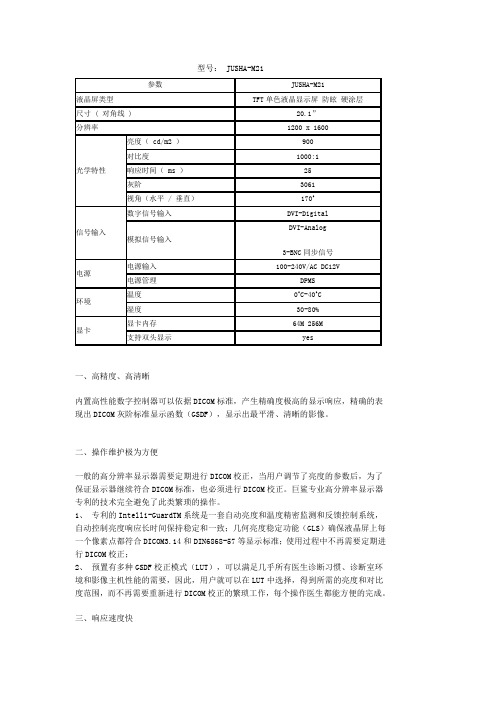
视频带宽增强技术(EVB)保证巨鲨专业高分辨率显示器拥有最快的响应速度,为25毫秒,是所有专业高分辨率显示器中最快的,EVB确保诊断医生读片时几乎不需要花费等待时间即可得到100%准确的影像显示,更能满足动态影像显示的需要。
四、蓝色背光系统(BLUEBASE)
巨鲨专业高分辨率显示器背光系统有蓝色背光(bluebase)和白色背光(clearbase)两种,用户可以根据自己的诊断习惯,选择不同背光的显示器。
五、超长的使用寿命
巨鲨专业高分辨率显示器背光系统寿命长达5万小时。
六、标配有防眩光保护屏
液晶屏是整个液晶显示器中最关键最贵重的部分,为避免医生诊断、观察、交流和教学时,液晶屏受到笔、手指等坚硬物接触而损伤或污染,每一台巨鲨高分辨率显示器出厂时都装配有防眩光的保护屏,即保证液晶屏不受损坏,又不会影响数字影像的显示效果。
七、独特的含金属外壳
外壳采用含金属的复合材料,保证巨鲨高分辨率显示器更加牢固耐用;加速显示器散热,延长显示器的寿命;抗干扰能力更强,有效地解决了与其它医疗仪器之间的相互干扰。
八、开放的接口
因为配有独特的输入接口,巨鲨2MP单色灰阶液晶显示器不仅可以提供精细的数字影像显示,还可以与各种影像主机的显示信号兼容,方便地替换各种主机原配的老化的CRT监示器。
联系人:史维
地址:江苏南京
电话:25-83305050
传真:25-83302899
E-Mail:shiwei19841228@
网址:。
马尔萨斯热显示柜产品说明书
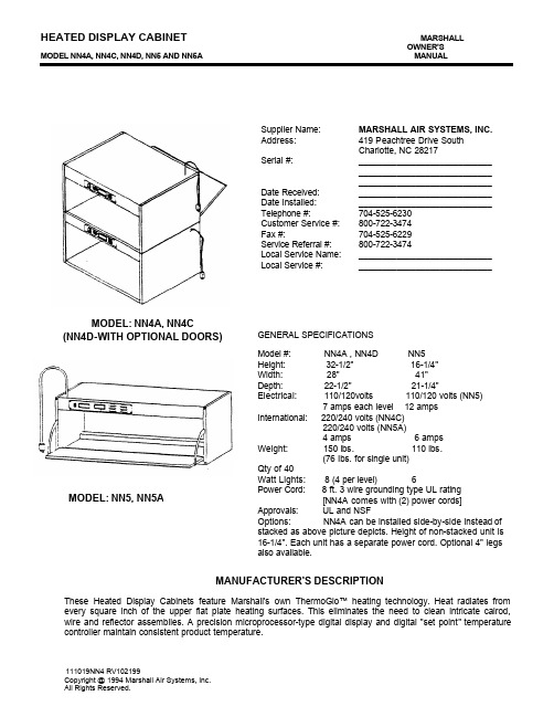
HEATED DISPLAY CABINET MARSHALLOWNER'S MODEL NN4A, NN4C, NN4D, NN5 AND NN5A MANUALSupplier Name: MARSHALL AIR SYSTEMS, INC. Address: 419 Peachtree Drive SouthCharlotte, NC 28217Serial #: ____________________________ ________________________________________________________ Date Received: ____________________________ Date Installed: ____________________________ Telephone #:704-525-6230 Customer Service #: 800-722-3474 Fax #:704-525-6229 Service Referral #: 800-722-3474Local Service Name: ____________________________ Local Service #: ____________________________MANUFACTURER'S DESCRIPTIONThese Heated Display Cabinets feature Marshall's own ThermoGlo™ heating technology. Heat radiates from every square inch of the upper flat plate heating surfaces. This eliminates the need to clean intricate calrod, wire and reflector assemblies. A precision microprocessor-type digital display and digital "set point" temperature controller maintain consistent product temperature.111019NN4 RV102199Copyright @ 1994 Marshall Air Systems, Inc. All Rights Reserved.MODEL: NN4A, NN4C (NN4D-WITH OPTIONAL DOORS)GENERAL SPECIFICATIONS Model #: NN4A , NN4D NN5 Height: 32-1/2" 16-1/4" Width: 28" 41" Depth: 22-1/2" 21-1/4"Electrical: 110/120volts 110/120 volts (NN5)7 amps each level 12 ampsInternational: 220/240 volts (NN4C)220/240 volts (NN5A)4 amps 6 ampsWeight: 150 lbs. 110 lbs.(76 Ibs. for single unit)Qty of 40Watt Lights: 8 (4 per level) 6Power Cord: 8 ft. 3 wire grounding type UL rating[NN4A comes with (2) power cords]Approvals: UL and NSFOptions: NN4A can be installed side-by-side instead of stacked as above picture depicts. Height of non-stacked unit is 16-1/4". Each unit has a separate power cord. Optional 4" legs also available.MODEL: NN5, NN5AMODEL NN4A, NN4C, NN4D, NN5 AND NN5AINSTALLATION1. Unpack unit and remove all protective paper or plastic covering from metal parts.2. Place cabinet on stable base. Make sure cooling air inlets, next to temperature controller, are notblocked.3. The unit should be caulked to the counter top as required by health department codes, or theoptional 4" legs (item 31 on page 4) should be ordered.4. Install 40 watt coated lights which were shipped loose.5. Plug unit into an AC 120V receptacle. The 220V International version of unit is furnished with cordonly.DAILY CHECKLIST AND CLEANING GUIDEOPENING CHECKLIST1. Turn on the power switch. The unit is ready to use after a 30 minute preheat period.2. The temperature controller on the unit is factory set for 450°F (232°C). With the control "ON", theactual temperature is displayed. The face plate of the control is either black or gray. The range ofset points available is from 400°F (204°C) to 450°F (232°C). The set point may be verified orchanged as follows:IF BLACK: depress the set button to view the set point. To change set point, use Up/Down arrowto select new set point while holding set button down.IF GRAY: depress the set button and RELEASE to view set point. To change set point, push "set"and, within three seconds, use Up/Down arrow to select new set point.CAUTION: PRESS ONLY WITH SOFT PART OF FINGER " DO NOT PUSH WITH SHARPOBJECT.3. In normal operation, the digital controller will display a value of approximately 480°F (248°C) highto 430°F (221°C) low.CLOSING CHECKLIST1. Turn off the unit and allow it to cool for 20 minutes.2. Pans and wire grates should be removed, washed in mild multi-purpose detergent, rinsed andsanitized.3. Clean unit and base with a damp cloth or non-abrasive cleaner.DO NOT IMMERSE UNIT IN WATER! DO NOT USE CAUSTIC CLEANING SOLUTIONS!4. Allow sufficient drying time before attempting to use.2MODEL NN4A, NN4C, NN4D, NN5 AND NN5APREVENTIVE MAINTENANCEFollow the daily schedule; there are no adjustments. The only user-replacement items are the light bulbs located under the top cover. If these fail, do the following:1. Unplug the unit.2. Remove the bulb(s) by carefully unscrewing them from their sockets.3. Replace the bulb(s) with a manufacturer's approved replacement part. (See parts list pages 4 & 5.)4. Check air flow through unit by feeling for air draw at slots on each side of temperature controller.TROUBLE SHOOTING CHARTIdentify problem in the left column and look for probable cause and solution in right hand column. Probable causes listed in the order they are most likely to happen. This sequence should be used to isolate the problem.Problem Probable Cause Solution1.No Light/No Heat Unplugged Circuit breaker istripped Plug in Reset breaker - call electrician if tripped twice Call Marshall Customer Service2.No Light/With Heat Light bulbs burned out Light switchdefective Unplug unit and replace bulbs Call Marshall Customer Service3.Temperature Controller Flashing999*Defective temperature controller orsensorCall Marshall Customer Service4.Temperature Controller DisplaysLess Than 400°F (204°C)*Loose sensor or defective heating unitassemblyCall Marshall Customer Service5.Low Product Temperature Set point too low Excessive air draft Reset to 450°F(232°C) Move unit orshield draft* NOTE: When replacing sensor, a special heat sink sealant will be present when removing failed sensor.Applying new sealant is not required; however, be sure to utilize existing sealant when mounting newsensor.3MODEL NN4A, NN4C, NN4D, NN5 AND NN5AITEM PART # DESCRIPTION ITEM PART # DESCRIPTION1110833Shelf Runner (2 Required)18502206Transformer 120V to 12V 2501484Screw #1 0 X.500"*501958Transformer 240V to 120V 3502064Sensor, RTD Temperature*502168Transformer 240V to 12V 4111194Sensor Guard (T'Glo 20" X 14")19114541Temperature Controller RTD 5111192Joining Tab (4 Required)20 *132499Temp Controller RTD (°C) 6502108Bushing 9/32" Dia.21500340Terminal Strip 3 Pole7501684Screw #10-24 X.750"22112925T'Glo 20" X 14"-120V8111024Swing Cover Plate111866T'Glo 20" X 14"-220V9502083Nylon Washer23501885Label: CAUTION HOT (not shown) 10111196Heat Deflector24502080Strain Relief11501864Switch Rocker25111380Door Assembly12501507Screw #10-24 X.500"26111387Door Guide Assembly (rightshown)13111195Faceplate Standoff111388Door Guide Assembly14110042Fan(left not shown)15501865Lamp Holder27111186Cord With Plug16502239Bulb Tuffskin 40 Watt28110904Cover-Side Panel Right 17110912Cover-side Panel-Left(no hole)29111187Cover-Side Panel Right(with hole)30110826Control Front Panel315002634"Leg(1)* These parts are for International (220V, 240V)units only.OPTIONAL:N/A 119844Side swing Doors (Pair)N/A 118771Mirror Mounting KitN/A 503413Kit, Temp. Control FaceplateDeg F REF: 1325744MODEL NN4A, NN4C, NN4D, NN5 AND NN5AITEM PART#DESCRIPTION ITEM PART # DESCRIPTION 1110903Shelf Runner (2 Required)17501507Screw #10-24 X.500" 2501484Screw #1 0 X.500"18502080Strain Relief3502108Bushing 9/32" Dia.19110042Fan4502064Sensor, RTD Temperature20110904Cover-Side Panel Right 5111310Sensor Guard (T'Glo 10" X 14")21500340Terminal Strip 3 Pole 6111547Door Assembly (Includes22502206Transformer 120V to 12V Handle, No Guides)*501958Transformer 240V to 120V 7501885Label: CAUTION HOT*502168Transformer 240V to 12V 8111310Sensor Guard (TGIo 20" X 14")23N/A Obsolete Part9502083Nylon Washer24111286T'Glo 20" X 14"-120V 10114541Temperature Controller RTD114433T'Glo 20" X 14"-220V 11501684Screw #10-24 X.750"25501865Lamp Holder12111024Swing Cover Plate26502239Bulb Tuffskin 40 Watt 13111387Door Guide Assembly (right shown)27110915T'Glo 10" X 14"-120V 14110895Control Front Panel 114434T'Glo 10" X 14"-220V 15114578Cord with Plug28 110912Cover-Side Panel-Left 16501864Switch Rocker29111388Door Guide Assembly(left shown)5* These parts are for International (220V, 240V) units only.OPTIONAL:N/A 120456Side swing Doors (Pair)N/A 118772Mirror Mounting KitN/A 503413Kit, Temp. Control FaceplateDeg F REF: 132574MODEL NN4A, NN4C, NN4D, NN5 AND NN5ALIMITED WARRANTYMARSHALL AIR SYSTEMS, INC., ("Marshall") warrants to the first purchaser ("Purchaser") all new equipment of its manufacture to be free of defects in material and factory workmanship for a period of one year from date of shipment provided that (i) the equipment is installed in the Continental United States, Canada or Hawaii and operated according to the Owner's Manual while located at the original address of installation, (ii) the warranty registration card has been completed and returned to the factory within fifteen (15) days after installation, and (iii) a post-installation start-up has been performed by an authorized service representative (portable equipment not applicable). Marshall's obligation under this warranty is limited to the repair or replacement at its option of any defective part. Under certain circumstances, Marshall will reimburse Purchaser for limited labor costs in replacing parts during a period of not more than ninety (90) days from date of shipment, provided that Labor Reimbursement instructions are followed and items i, ii, and iii above are completed. See special provision for portable equipment. It is understood that Marshall's obligation with respect to equipment located outside the Continental United States, Canada or Hawaii is limited to replacement parts only.Because Marshall does not and cannot control Purchaser's installation, use, and maintenance of equipment manufactured by Marshall, this warranty DOES NOT COVER:1. Any equipment calibration;2. Any component disassembled in the field;3. Damage due to improper cleaning and/or abuse, i.e. burner rotation, grease accumulation in electricalcomponents or plugs (hosing or "watering down" equipment will cause electrical failures not covered bywarranty);4. Blown fuses or bulbs, motor brushes, and Teflon components;5. Any replacement parts used on the equipment which are not purchased from Marshall;6. Accessory components not installed and/or manufactured by Marshall.Shipping damage must be reported to the carrier and is not covered under this warranty. Marshall will not be liable for damage as a result of improper installation, misuse, abuse, alteration of original design, incorrect voltage, unauthorized service, breakage of fragile items, or any other damage caused by an act out of Marshall's control.The effect of corrosion, fire, and normal wear on the equipment or component parts is not covered by this warranty. This warranty does not cover cooking performance, smoke capture or holding temperatures which is a function of food types, textures, temperatures, equipment line ups and other variables chosen by the Purchaser and over which Marshall has no control. This warranty does not apply to damage caused by accident or to damage caused by the negligence of Purchaser or the employees of Purchaser or to damage caused by lightning generated electrical current or any other Act of God whatsoever. This warranty does not apply to any equipment bearing a serial number which has been tampered with or altered. Marshall reserves the right to accept or reject any such claim in whole or in part. Marshall will not accept the return of any product without prior written approval from Marshall, and all such approved returns shall be made at Purchaser's sole expense.THIS WARRANTY IS IN LIEU OF ALL OTHER WARRANTIES, EXPRESS OR IMPLIED, INCLUDING THE IMPLIED WARRANTY OF MERCHANTABILITY AND THE IMPLIED WARRANTY OF FITNESS FOR A PARTICULAR PURPOSE, OR PATENT OR OTHER INTELLECTUAL PROPERTY RIGHT INFRINGEMENT, AND EXCEPT FOR THE EXPRESS WARRANTY CONTAINED HEREIN, THE EQUIPMENT IS SOLD "AS IS." REMEDIES UNDER THIS WARRANTY AND UNDER ANY WARRANTY THAT MAY SURVIVE THE DISCLAIMER OF WARRANTIES ARE LIMITED EXCLUSIVELY TO THOSE REMEDIES DESCRIBED ABOVE. NO OTHER REMEDY IS AVAILABLE UNDER THIS WARRANTY OR ANY OTHER WARRANTY. NEITHER THIS WARRANTY NOR ANY OTHER WARRANTY COVERS, AND MARSHALL WILL NOT BE RESPONSIBLE FOR, ANY INCIDENTAL OR CONSEQUENTIAL DAMAGES, INCLUDING BUT NOT LIMITED TO THE COST OF DISASSEMBLY AND SHIPMENT OF THE EQUIPMENT, PRODUCTION OR PRODUCT LOSSES, INJURY TO OTHER PROPERTY, OR LOST PROFITS RESULTING FROM THE USE OF OR INABILITY TO USE THE PRODUCTS OR FROM THE PRODUCTS BEING INCORPORATED IN OR BECOMING A COMPONENT OF ANY OTHER PRODUCT OR GOODS, OR OTHER LOSSES. WHERE, DUE TO OPERATION OF LAW, CONSEQUENTIAL AND INCIDENTAL DAMAGES CANNOT BE EXCLUDED, THEY ARE EXPRESSLY LIMITED IN AMOUNT TO THE PURCHASE PRICE OF THE EQUIPMENT.FOR INTERNATIONAL INSTALLATIONS " PLEASE CONTACT YOUR LOCAL MARSHALL AIR SYSTEMS RECOGNIZED DISTRIBUTOR.7MODEL NN4A, NN4C, NN4D, NN5 AND NN5AWARRANTY PROCEDURESRETURN GOODS AUTHORIZATION FOR PARTS - FACTORY DIRECTFor prompt warranty parts replacement and RGA processing, please call Marshall's Customer Service Department at 800-722-3474 or 704-525-6230 for assistance. In all cases, a Return Goods Authorization (RGA) number must be issued by Marshall Air Systems, Inc. Unauthorized returns will not be processed.Option #1: Purchaser to return part prepaid to Factory, Marshall to repair or replace at own expense if defective, and ship part back to Purchaser prepaid.Option #2: Marshall to furnish replacement part freight prepaid with or without requesting return of the defective part. WARRANTY LABOR REIMBURSEMENT AND/OR PARTS REPLACEMENT THROUGH RECOGNIZED SERVICE AGENCYTo be reimbursed for warranty labor costs, authorization must be given by Marshall Air Systems, Inc. Unauthorized work will not be reimbursed. Work must be performed by a Marshall Air Systems Recognized Service Agency within the service time allowance guidelines and must be submitted along with failed parts (if applicable) to Marshall Air Systems (freight prepaid) within 30 days of the work being performed. Travel is covered, but must not exceed 50 miles or 1 hour, whichever is greater. Call Marshall's Service Department at 800-722-3474 or 704-525-6230 with any questions. Service is to be performed by recognized service agencies during normal working hours. Owner to pay for all other charges including excessive travel or overtime charges. DIAGNOSTIC LABOR CHARGES ARE INCLUDED IN SERVICE TIME ALLOWANCE GUIDELINES. All portable equipment (under 90 pounds) shall be delivered by Purchaser, at his/her expense, to the nearest authorized service agency for in-shop repair or at Purchaser's discretion he/she will pay all travel time and mileage expenses for portable equipment.NON-WARRANTY RETURNS:All items returned for customer convenience are subject to a 20% restocking fee. In the event of an error by MarshallAir Systems, Inc., a Returned Goods Authorization will be issued for full credit.FOR INTERNATIONAL INSTALLATIONS - PLEASE CONTACT YOUR LOCAL MARSHALL AIR SYSTEMS RECOGNIZED DISTRIBUTOR.8。
巨鲨(JUSHA)显示器用户手册

何手动设置,只需将显示器连接至计算机即可设定最佳分辨率与刷新率。
显示器仅支持以下显示模式:
分辨率
刷新率
标准
备注
640 x 480 800 x 600
60Hz 60Hz
VGA VESA
C21、M11、M21 C21、M11、M21
1024 x 768
60Hz
VESA
C21、M11、M21
1280 x 1024
002
巨鲨专业高分辨液晶显示器用户手册
警告 如果设备开始冒烟并伴有焦糊味,或者发出奇怪的噪音,请立刻切断电源,然后与上 海巨鲨商贸有限公司联系以获得帮助。 使用有故障的设备可能导致起火、电击或设备损坏。 由合格的维修人员进行各种维修。 不要拆开机壳或者修改设备。不要试图自行维修此显示器。 拆开机壳或修改设备可能导致起火、电击或设备损坏。
2.1. 特征
- 适应VGA模拟输入(仅M11、M21、C21机型支持) - 适应BNC同步输入(仅M11、M21机型支持) - 适应DVI数字输入(TMDS) - 分辨率: 1M像素(1280点 x 1024线)/ 2M像素(1600点 x 1200线)
3M像素(2048点 x 1536线)/ 5M像素(2560点 x 2048线) - 高度可调整底座 - 亮度稳定控制电路 - 可以纵向/横向显示
请保留好原始包装。若需要再次发送本产品,请务必使用原始包装。货物运输时请
勿重压。
006
巨鲨专业高分辨液晶显示器用户手册
2.3. 控制与接口
JUSHA-C21、M11、M21、M31侧面
JUSHA-M51机型侧面
背面(JUSHA-C21)
(1) 自动调整按键(M31机型该键无作用) (2) 控制按键(向上) (3) 控制按键(向下) (4) 菜单/确认按键 (5) 退出按键 (6) 电源开关 (7) 电源指示灯
KONICA MINOLTA 显示器色彩分析仪 CA-210 说明书

安全标识符号在本使用手册中,以下标识用于避免可能因错误使用本仪器而导致的事故。
表示有关安全警告或注意的内容。
仔细阅读此内容,确保安全并正确使用。
表示有关火灾的安全防范内容。
仔细阅读此内容,确保安全并正确使用表示有关触电的安全防范内容。
仔细阅读此内容,确保安全并正确使用表示违禁操作。
切忌进行该项操作。
表示说明指令。
必须严格遵守该项指令。
表示说明指令。
从AC插座上拔出AC电源线。
表示违禁操作。
切勿拆卸本仪器。
表示说明指令。
按照指示连接接地端子。
SIP/SOP 连接•用于连接模拟及数字接口的附件设备必须经过鉴定,以达到国际电工委员会(IEC)制定的标准(即,数据处理设备的IEC 60950标准)。
•此外,所有配置都必须遵守IEC 61010-1系统标准。
任何人将附加设备连接至信号输入配件或者信号输出配件时,都要配置一个测量系统的电气设备,而且,鉴于该要求,需要对该系统符合系统标准(IEC 61010-1)的要求承担责任。
如果有疑问,请向技术服务部或者当地代表咨询。
关于本手册的注意事项•在没有得到柯尼卡美能达公司准许的情况下,严禁擅自复制或再版本手册的部分或全部内容。
•本手册的内容若有变动,恕不另行通知。
•我们在撰写本手册时已尽量确保其内容的准确性。
但是若有疑问或发现任何问题,请联系柯尼卡美能达公司的授权维修机构。
•对于因使用本仪器所造成的后果,柯尼卡美能达公司不承担任何责任。
安全防范措施为了确保正确使用该仪器,请仔细阅读并严格遵守以下要点。
阅读手册之后,请妥善保存,以备出现问题时参考。
前言感谢您购买显示器色彩分析仪CA-210。
该装置设计的目的是利用通用测量探头测量各种类型的彩色显示器的色彩以及亮度,或者利用液晶闪烁测量探头测量彩色液晶显示屏的色彩、亮度和闪烁情况。
在使用本装置前,请认真阅读本手册。
使用注意事项●本装置仅为室内使用设计,切勿在室外使用。
●由于本装置是由精密的电子元件制作而成,切勿拆卸。
pro-face sp5000系列 硬件手册说明书

目录
SP5000-MM01-CS-PDF_O
安全信息 ....................................................................................................7 关于本书 ....................................................................................................8 概述......................................................................................................... 11
对于将本指南或其内容用作商业用途的行为,施耐德电气未授予任何权利或许可,但 以“原样”为基础进行咨询的非独占个人许可除外。
施耐德电气的产品和设备应由合格人员进行安装、操作、保养和维护。
由于标准、规格和设计会不时更改,因此本指南中包含的信息可能会随时更改,恕不 另行通知。
在适用法律允许的范围内,对于本资料信息内容中的任何错误或遗漏,或因使用此处 包含的信息而导致或产生的后果,施耐德电气及其附属公司不会承担任何责任或义 务。
标准主机模块 ................................................................................28 增强型主机模块............................................................................. 30 开放型主机模块............................................................................. 32 LED 指示 ......................................................................................34 显示模块 ............................................................................................35 精良显示模块 ................................................................................35 高级显示模块 ................................................................................39 LED 指示 ......................................................................................42 规格......................................................................................................... 44 一般规格 ............................................................................................44 电气规格....................................................................................... 44 环境规格....................................................................................... 46 结构规格....................................................................................... 47 功能规格 ............................................................................................49 显示规格....................................................................................... 49 存储器 ..........................................................................................51 时钟 .............................................................................................51 触摸屏 ..........................................................................................51 接口规格 ............................................................................................52 接口规格....................................................................................... 52 接口连接....................................................................................... 54 用于 COM1/COM2 的串行接口 (RS-232C 和 RS-422/RS485) .............................................................................................57 辅助输出/扬声器输出接口 (AUX) ....................................................59 DVI-D 输出接口.............................................................................60 尺寸......................................................................................................... 62 标准主机模块...................................................................................... 62 SP-5B00 ......................................................................................62 增强型主机模块 ..................................................................................63 SP-5B10 ......................................................................................63 开放型主机模块 ..................................................................................63
- 1、下载文档前请自行甄别文档内容的完整性,平台不提供额外的编辑、内容补充、找答案等附加服务。
- 2、"仅部分预览"的文档,不可在线预览部分如存在完整性等问题,可反馈申请退款(可完整预览的文档不适用该条件!)。
- 3、如文档侵犯您的权益,请联系客服反馈,我们会尽快为您处理(人工客服工作时间:9:00-18:30)。
10年 巨鲨专业显示器的历史
4,000 近
家 与巨鲨合作的医院数量
100,000,000元 2010年巨鲨专业显示器销售额
VS.
为什么医学诊断必须用医用专业显示器?
Resolution 分辨率
1MP=1280x1024=1024x1280 2MP=1600x1200=1200x1600 3MP=2048x1536=1536x2048 4MP=2560x1600 5MP=2560x2048=2048x2560 9MP=3840x2400
亮度(cd/m2) 亮度(cd/m2)
GSDF
1000 100 10
1 0
0.1 0.01
200 400 600 800 1000
JND 指数
1000.00
100.00
10.00
1.00 0.10
0
对照表 0
显示器
GSDF
50 100
520
700
150 200 P 输入值
250
1500
DICOM 3.0 第14节
巨鲨 专业显示器特点
8 外置直流电源模块 外置直流电源模块提供了精密的直流供电,确保图像质量更稳定,一旦出现电源 甚至医生就能够方便的更换。
巨鲨 专业显示器特点
9 多种输入输出接口 JUSHA各种专业显示器配备多种数字或模拟视频信号输入输出接口,可满足医院 种医疗影像显示的需要。DVI-D,VGA,复合视频BNC,S端子,Y/C,RGB/分 SD/HD-SDI接口等。
(1)ISO 13406-2 标准
关键指标——亮度
➢它是表示背灯管光源所能产生的最大亮度 ➢单位:尼特 Nit ➢1 nit = 1 cd/m2
(1)ISO 13406-2 标准
关键指标——信号响应时间
➢液晶显示器对于输入信号的反应速
度,也就是液晶由暗转亮或由亮转暗 的反应时间,通常是以毫秒(ms)为单位
1 高分辨率显示精细图像 最高达到9兆的超高的分辨率可以在一个显示器上展现更多的细节,选择不同规 格的巨鲨专业显示器来满足各种医学影像高分辨率显示的需要。
巨鲨 专业显示器特点
2 12bit (3061级) 灰度值 内置高性能数字控制器,产生高达12bit (3061级) 的灰阶深度,更精确地表现出 阶标准显示函数GSDF,显示出最平滑、最逼真的图像。
DICOM 校正:医用专业显示器必备功能
DICOM协议保证了 1. 图像的细腻性
- 展示更多的细节
2. 图像一致性 - 无论何时何地,图像显示一致性,保证诊断正确性
数字化诊断必须使用专业显示器 !
➢分辨率 ➢亮度 ➢灰阶度 ➢DICOM校正
巨鲨 全面医疗显示解决方案
JuSha Comprehensive Health Care Solutions
巨鲨显示器120202
课程内容
巨鲨专业显示器简介 液晶显示技术基础知识 医用专业显示器 vs. 民用显示器 巨鲨专业显示器新品介绍:70寸和26寸双屏
巨鲨集团的历史
与巨鲨合作的医院数量
液晶显示技术基
液晶显示器构成
液晶面板成像原理
➢偏光板是使不具偏极性的自然光,产生偏极化,转变成偏极光 ➢液晶分子:扭转特性,使光线扭转 ➢液晶分子未施加电压时,排列杂乱无章;施加电压,定向排列
巨鲨 专业显示器特点
3 高精度图形显示卡 配合JUSHA高精度图形显示卡,才能显示出更高精度、更高速、更稳定的2D 和3D医疗图像。
高速图像处理芯片 PCI-E2.0高速插槽 内存高达512M 数据传输速度5Gb/秒
PCI插 内存1 192M
巨鲨 专业显示器特点
4 全屏幕亮度均衡系统SLE 所有巨鲨显示器采用全屏幕亮度均衡系统SLE,确保了在整个液晶面上亮度的一 。 Full screen luminance ecology
巨鲨:3061级 11.58bit,通常也叫做12bit
Gray Scale Terminology 灰阶度
医用10bit以上灰阶
民用8bit灰阶
为了作出准确的诊断,要求医用显示器实行10bit以上灰阶。
DICOM 3.0 第14节
统一医疗影像的显示 - 显像函数 GSDF(Grayscale Standard Display Function 灰阶标准显像函数)
影像诊断系列
—— 全面医疗显示解决方案
5M/3M/2M/1M灰阶专业显示器 3M/2M/1M彩色专业显示器
CT、磁共振专
9M彩色专业显示器
4M彩色专业显示器
临床浏览系列
—— 全面医疗显示解决方案
1M彩色专业显示器
2M彩色专业显示器
1M单色专业显示器 2M单色专业显示器
会诊系列
—— 全面医疗显示解决方案
1. 在屏幕中心处测量,保证准确性 2. 比其他置于前框的亮度计检测面积大30倍。
巨鲨 专业显示器特点
6 白色/蓝色背光系统 针对不同医生的观片习惯,可以选择不同色温的背光系统的巨鲨灰阶显示器。
清晰背光
蓝色背光
巨鲨 专业显示器特点
7 防眩光保护屏,金属外壳 为避免医生习惯性用手指或笔尖触碰昂贵的液晶面,巨鲨灰阶诊断安装了有双面 涂层的专业保护屏,有效的避免了人为污染或损伤,又不会影响诊断质量。独有 材料的外壳确保了巨鲨专业显示器拥有更好的屏蔽性、散热更快。
1MP:BNC接口,支持模拟信号
巨鲨 专业显示器特点
10 远程质量控制体系 巨鲨专业显示器的质量管理系统v1.0可以对专业显示器的分辨率、亮度、眩光、 等指标进行监测和DICOM的校正。可以通过计算机网络,远程监测和控制所有巨 业显示器的状态。
我们的新产品
Our new products
70寸超大屏幕会诊专用屏 应用领域
CT、磁共振专用屏
最新科技创新之举---在一台显示器上实现双屏的应用
CT、磁共振专
CT、磁共振专用屏
CT
26寸
内置最符合CT磁共振读片模式的 DICOM曲线
ห้องสมุดไป่ตู้
多排CT的飞速发展,更大尺寸显示更多幅 诊断工作站的影像对照和比较学研究 适应CT、MRI更多的彩色应用 比传统双屏更加完美的“一致性”
C26=1920x120 70寸=1920x10
常用民用显示器分辨率:1024x768, 1024x800, 1280x1
Gray Scale Terminology 灰阶度
Luminance (brightness) 亮度
1 ni
民用显示器:一般亮度为200-300cd/m2;无亮度恒定的要求; 医用显示器:一般亮度为600-1000 cd/m2;经过校正设定亮度在400-
70寸超大屏幕会诊专用屏
影象主机、超声、内窥、手术室系列
—— 全面医疗显示解决方案
内窥手术专用显示器15”19”24”26’
影像主机专用CRT
24”26”40”手术室专用显示器
巨鲨 专业显示器特点
JuSha Display Expert Features
巨鲨 专业显示器特点
High resolution provide precise image 12bit (3061 tones) grayscale High precision graphic card
VIP综合影像会 影像中心教学读 远程医疗、电教 数字化手术示教
VS.
产品对比
液晶显示 直接成像
光影投射 间接成像,幕布材质平整度、均 性也都会影响色度和亮度的发
图像显示效果更清晰 诊断结果更准确
产品对比
液晶点阵固定排列 不会产生几何失真
光影投射
图像效果完全靠目测,没有定量 理论上说不可能调节到没有几几何何失
Full screen luminance ecology DICOM3.14 auto calibration Ins-guard
Clear base/blue base Panel protector and metal frame Outside DC power supply module
Multi in-out interface Remote QC system
巨鲨 专业显示器特点
5 DICOM3.14自动校正Ins-guard系统 Ins-guard是一套亮度实时监测和自动反馈控制系统,自动保证液晶面上每个像素 度输出都符合DICOM/DIN6868-57标准,使用过程中不再需要繁琐的手工校正。
3
1. 出厂前,高精度测光仪测量每
块液晶面板的特征显示曲线,
1 2 3 4 5 6 7 8 9 10
高分辨率显示精细图像 12bit (3061级) 灰度值 高精度图形显示卡 全屏幕亮度均衡系统SLE DICOM3.14自动校正Ins-guard系统 白色/蓝色背光系统 防眩光保护屏,金属外壳 外置直流电源模块 多种输入输出接口 远程质量控制体系
巨鲨 专业显示器特点
屏;其余的为170度
巨鲨 关于我们
JuSha About Us
医用诊断显示器的发展
CRT时代
2000年ID-tech推出医用液晶面板高亮度 、宽视角
2002年巨鲨和主要竞争对手几乎同期进 显示器领域。
技术壁垒被打破,到目前为止全球出现 液晶医用显示器品牌,但大部分都已退 。
巨鲨 医用诊断 LCD研发生产的领导者
不断创新的研发
+
严格的生产流程
Le
➢市场占有率稳居第一 ➢第一个在全球推出70寸超大屏幕会诊中心,9M,CT磁共振专用显示器 ➢唯一被选中用于2008年北京奥运会、2010年广州亚运会医疗中心 ➢唯一可以在国内完成所有维修
影像诊断
临床浏览
会诊示教
全方位医疗显示技术
内窥系统
