阀堵工艺工装设计及CADCAM
名词解释和简答机械CAD与CAM复习资料

➢一.名词解释.➢ 1.计算机辅助设计(CAD)☞指工程技术人员以计算机为辅助工具来完成产品设计过程中的各项工作的技术,包括草图绘制、零件设计、装配设计、工装设计、工程分析、真实感及渲染等。
➢ 2.计算机辅助工艺规程设计(CAPP)☞指工艺人员借助于计算机,根据产品制造工艺要求,交互地或自动地确定产品加工方法和方案,包括加工方法选择、工艺路线确定、工序设计等。
➢ 3.计算机辅助制造(CAM)☞广义CAM:指借助计算机来完成从生产准备到产品制造出来的过程中的各项活动,如计算机辅助数控加工编程、制造过程控制、质量检测与分析等。
☞狭义CAM:通常指NC程序编制,包括刀具路径规划、刀位文件生成、刀具轨迹仿真及NC代码生成等。
二.简答题1.CAD/CAM系统的设计原则➢(1)系统的总体设计原则➢①实用化原则, ②适度先进性原则, ③系统性原则, ④整体设计与分布实施原则➢(2)硬件选型原则➢①系统功能与能力②系统的开放性与可移植性③系统升级扩展能力④良好的性能价格比⑤系统的可靠性、可维护性与服务质量➢(3)软件选型原则➢①系统功能与能力配置②软件性能价格比③与硬件匹配性④二次开发能力与环境⑤开放性⑥可靠性2.线框建模特点(5个优点,3个不足)➢①所需的信息量最少➢②数据结构简单➢③占用存储空间小➢④对硬件要求不高➢⑤显示响应速度快➢⑥存在多义性➢⑦不能自动进行可见性检验及消影➢⑧物体的几何特性、物理特性计算困难3.表面建模特点(p125)➢①完整地定义了三维物体的表面,有助于对零件进行渲染等处理,有助于CAM系统直接提取有关面的信息生成数控机床的加工指令。
➢②有助于对物体的几何特性和物理性能等方面的计算,如表面积、容积、重量、形心位置、惯性矩等。
➢③用户可以直观的从事产品外形设计,避免表面形状设计的缺陷。
➢④可以为CAD/CAM系统的其它场合提供数据,如有限元分析中的网格划分等。
➢⑤无法表达产品的立体属性。
CADCAM技术

第一章1、CAD基本功能:几何造型,工程分析,仿真模拟,图形处理。
2、CAPP功能:毛坯设计→工艺路线→工序设计(机床刀具选用,工装设计,余量分配,切削用量,工时定额,工序图绘制)→工艺文件。
3、广义CAM:利用计算机完成从毛坯到产品制造过程中的直接和间接的各种生产活动,包括工艺准备、生产作业计划、物流控制、质量保证等。
狭义CAM:数控加工编程。
4、CAD/CAM集成技术:利用数据库技术、网络技术、数据交换和接口技术,实现CAD/CAPP/CAM各模块之间信息自动传递、转换和共享的相关技术。
5、CAD/CAM系统作业过程:创意与构思,计算机辅助设计与分析,快速原型制造,计算机辅助工艺规划,计算机辅助编程,虚拟制造。
6、CAD/CAM作业过程特征:设计对象数字化,设计环境的网络化,设计过程的并行化新型开发工具和手段7、CAD/CAM系统硬件组成:主要由计算机主机、输入设备、输出设备、存储器、生产装备以及计算机网络等几部份组成。
第四章1.窗口矩形观察框,用以显示感兴趣的图形内容。
窗口一般用矩形对角坐标表示。
涉及图形剪裁技术。
窗口也可定义为圆形、多边形等异型窗口。
窗口可以嵌套。
2、视区在图形设备上定义的矩形区域。
视区同样用矩形对角坐标表示。
视区应小于等于屏幕区域,可在同一屏幕上定义多个视区。
3、窗口与视区坐标点的变换:可见:①若视区大小不变,窗口缩小或放大,会使图形放大或缩小。
②若窗口大小不变,视区缩小或放大,则图形会跟随缩小或放大。
③若窗口与视区大小相同时,则图形大小比例不变。
④若视区与窗口纵横比不同时,则图形会产生伸缩变形。
4、剪裁:保留窗口内的图形,裁去窗口之外图形的处理技术。
直线段与窗口间的关系:1) 整条线段在窗口内,显示整条线段,无须剪裁;2) 整条线段在窗口外,不需显示该线段,无须剪裁;3) 部分在窗口内,部分在窗口外,需将窗口外部分剪裁掉。
5、绘图方式:交互式绘图,程序参数化绘图,尺寸驱动式参数化绘图。
阀体工艺设计课程设计

阀体工艺设计课程设计一、课程目标知识目标:1. 让学生掌握阀体工艺设计的基本原理,理解阀体的结构特点及其在工程中的应用。
2. 使学生了解并掌握阀体加工工艺流程,包括铸造、机械加工、表面处理等环节。
3. 帮助学生掌握阀体材料的选择原则,理解不同材料的性能及其对阀体性能的影响。
技能目标:1. 培养学生运用CAD软件进行阀体结构设计的能力,提高其空间想象力和创新能力。
2. 培养学生运用CAM软件对阀体加工工艺进行编程和优化的能力,提高其解决实际工程问题的能力。
3. 提高学生团队协作能力,使其能够在项目中进行有效的沟通与分工。
情感态度价值观目标:1. 培养学生对阀体工艺设计的兴趣,激发其学习热情,形成积极的学习态度。
2. 培养学生的工程意识,使其关注我国阀门制造业的发展,增强国家意识和社会责任感。
3. 培养学生严谨细致的工作作风,提高其质量意识,为未来从事相关工作奠定基础。
本课程针对高年级学生,结合学科特点,注重理论知识与实践技能的结合,培养学生具备解决实际工程问题的能力。
课程目标具体、可衡量,旨在使学生在掌握阀体工艺设计相关知识的基础上,提高综合运用所学知识解决实际问题的能力。
同时,注重培养学生的团队协作精神、创新意识和工程素养,为我国阀门制造业输送高素质的专业人才。
二、教学内容1. 阀体工艺设计原理:包括阀体结构、工作原理及其在工程中的应用,对应教材第1章。
2. 阀体材料及性能:介绍阀体常用材料,分析不同材料的性能特点及选择原则,对应教材第2章。
3. 阀体加工工艺:讲解阀体的铸造、机械加工、表面处理等工艺流程,对应教材第3章。
4. 阀体结构设计:运用CAD软件进行阀体结构设计,包括草图绘制、三维建模、装配等,对应教材第4章。
5. 阀体加工工艺编程:利用CAM软件对阀体加工工艺进行编程和优化,对应教材第5章。
6. 阀体工艺设计实例:分析典型阀体工艺设计案例,使学生掌握实际工程中的应用,对应教材第6章。
CADCAM简介

应用 数据库层
数据库系统 网络层 操作系统
分布式关系数据库系统(、OpenBASE、DM) TCP/IP、Intranet/LAN Windows、Unix
CAM有广义和狭义两种定义。广义的CAM是指工程技 术人员在计算机组成的系统中以计算机为辅助工具,完 成从准备到产品制造整个过程的活动,包括工艺过程设 计、工装设计、NC自动编程、生产作业计划、生产控 制、质量检测与分析等。狭义的CAM通常是指数控 (Numerical Control,简称NC)程序编制,包括刀具路 径规划、刀位文件生成、刀具轨迹仿真及NC代码生成 等。在生产过程中,使用CAM技术能提高生产质量、 减低成本、缩短生产周期、改善劳动条件等。
真实感模型
比例油土模型
复杂曲面设计
CAE是用计算机辅助求解复杂工程和产品结
构强度、刚度、屈曲稳定性、动力响应、热传
导、三维多体接触、弹塑性等力学性能的分析
计算以及结构性能的优化设计等问题的一种近
似数值分析方法。可对产品的实体模型进行评
估,及早发现设计缺陷,并能正确评价计算分
析结果。
波音777的研发过程中采用CAE数字化样机技术, 节省了大量物理样机试飞次数,仅一次试飞即获 得成功,而每次物理样机实验需花费1亿美元。 CAE技术在汽车工业中的应用,使新车开发周期 由原来的5~6年缩减到现在的1~2年。
“鲨鱼皮”背后的神秘技术
北京奥运会 “水立方”在 9天内我们见证了19项新 的世界纪录和7项新的奥运会纪录的诞生,见证了 泳坛巨星菲尔普斯身着“鲨鱼皮”泳衣勇夺8金的 奥运传奇…… “鲨鱼皮”在水立方掀起的夺金狂潮,让这款泳衣在 国人心中愈加神秘;其实“鲨鱼皮”泳衣正是应用 了CAE技术,下面让我们来了解CAE技术是如何铸 就“鲨鱼皮”的传奇的。
CADCAM-第一章.概述
一、CAD/CAM的基本功能
交
图
存
输
互
形
储
入
功
显
功
输
能
示
能
出
功
功
能
能
1.交互功能
人机接口是CAD/CAM系统中用户与系统连接的
桥梁
友好的用户界面,是用户直接而有效地
完成复杂设计任务的必要条件
除软件中界面设计外,还必须有交互设 备实现人与计算机之间的不断通信
2.图形显示功能
CAD/CAM是一个人机交互的过程,从产品的造型、 构思、方案的确定,结构分析到加工过程的仿真,系 统随时保证用户能够观察、修改中间结果,实时编辑 处理。
产品设计阶段
设计人员以计算机为辅助工具完成各项工作, 即计算机辅助设计(Computer Aided Design,CAD)。
生产准备阶段
工艺人员借助计算机根据产品设计阶段给出的 信息和产品制造的工艺要求,交互或自动地完成各 项工作,即计算机辅助工艺过程设计
(Computer Aided Process Planning,CAPP)。
空间的保障。
CAD/CAM系统运行时,数据
量很大,有很多算法往往生成
大量的中间数据,尤其是对图
形的操作、交互式的设计以及
IBM737Байду номын сангаасMagnetic core
storage unit
结构分析中的网格划分等。
4.输入输出功能
CAD/CAM系统运行中,用户需不断地将有关设计 的要求、各步骤的具体数据等输入计算机内,通过计 算机的处理,能够输出系统处理的结果。
生产人员完成从生 产准备到产品制造 出来的过程中的各 项活动,包括作业 计划、零件加工、 装配和性能检验。
CAD_CAM概述
1.2 计算机辅助工艺设计CAPP
概念:
工艺设计是从产品设计到产品制造之间的重要 桥梁,也是机械制造企业生产技术工作的主要 内容。 在工艺设计阶段,要完成毛坯设计,工艺规程 设计、工装设计等任务。如果借助计算机来完 成这些任务,称为CAPP。
10
1.2 计算机辅助工艺设计CAPP
手工制订工艺规程存在的问题:
准确地说,CAE是指产品设计中的分析计算与分析仿
真,具体包括工程数值分析、结构与过程优化设计、 强度与寿命评估、运动/动力学仿真。
CAE是CAD成的概念
把CAD、CAM 、CAE、CAPP等各种功能不 同的软件有机的结合起来,用统一的执行机 制来组织各种信息的提取、交换、共享和处 理,以保证系统内信息的畅通。
由于工艺设计人员的经验、习惯和技术水平不同, 对同一零部件产品的工艺设计会存在差异,不利于 工艺规程的标准化; 效率低下,存在大量的重复劳动; 不能将工艺专家的经验和知识集中起来加以利用。
11
1.2 计算机辅助工艺设计CAPP
CAPP基本功能:
接收或生成零件信息
检索标准工艺文件
选择加工方法
安排加工路线
26
2.1 硬件组成
联机系统的联网方式: 总线型拓扑 星型拓扑 环型拓扑 网状拓扑 混合型拓扑结构
27
总线型拓扑
28
网状拓扑
29
环型拓扑
30
星型拓扑
31
混合型拓扑结构
32
2.2 软件组成
CAD软件组成一般包括系统软件、支撑软件和 应用软件。 系统软件:主要负责管理硬件资源和各种软件 资源。 支撑软件:实现CAD/CAM各种功能的通用应 用基础软件。 应用软件:用户为了解决某个实际问题而开发 出来的软件(在支撑软件的基础上经过二次开 发,或者针对特定需求开发的独立软件)。
计算机辅助设计与制造(CADCAM)
一、CAD/CAM概论本章主要是讲解CAD/CAM的基本概念、基本功能和工作原理等。
CAD/CAM技术是一门多学科综合性应用技术,是20世纪制造领域最杰出的技术之一。
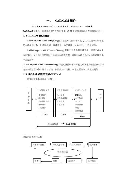
1.1 CAD/CAM的基本概念CAD(Computer Aided Design):是指工程技术人员以计算机为工具完成产品设计过程中的各项任务,如草图绘制、零件设计、装配设计、工装设计、工程分析等;CAPP(Computer Aided Process Planning):是指工艺人员利用计算机,根据产品制造工艺要求,交互或自动地确定产品加工方法和方案,如加工方法的选择、工艺路线和工序的设计等;CAM(Computer Aided Manufacturing):制造人员借助于计算机完成从生产准备到产品制造出来的过程中各个环节与活动,如数控加工编程、制造过程控制、质量检测等。
1.1.1 从产品制造的过程理解CAD/CAM传统制造概念与过程如图1。
1现代制造概念与过程利用计算机完成各个环节的工作成为CAD/CAM几点说明:1、计算机技术只能解决信息的查询与统计,信息的管理、重复而繁琐的工作等,而并不能代替人的工作,特别是创造性的工作。
2、现代制造概念很大,本书CAD/CAM的概念只涉及到产品的设计、工艺设计、加工、车间控制与质量控制等内容。
3、上述制造环中有三个流:物流、资金流与信息流。
4、企业制造资源有人、财、物、技术与信息。
1.1.2 CAD/CAM的基本功能在CAD/CAM系统中,人们利用计算机完成产品结构描述、工程信息表达、工程信息的传输与转化、信息管理等工作。
因此,CAD/CAM系统应具备以下基本功能:1、产品与过程的建模如何用计算机能够识别的数据(信息)来表达描述产品。
如产品形状结构的描述、产品加工特性的描述、如何将有限元分析所需要的网格及边界条件描述出来等等。
2、图形与图象处理在CAD/CAM系统中,图形图象仍然是产品形状与结构的主要表达形式,因此,如何在计算机中表达图形、对图形进行各种变换、编辑、消隐、光照等处理是CAD/CAM的基本功能。
阀体加工工艺课程设计
阀体加工工艺课程设计一、课程目标知识目标:1. 学生能理解并掌握阀体加工的基本工艺流程,包括铸造、机械加工、热处理等关键环节。
2. 学生能掌握阀体加工中常用的加工方法和设备,了解不同加工工艺的适用范围和优缺点。
3. 学生能了解阀体加工中的质量控制要点,包括尺寸精度、表面质量等技术要求。
技能目标:1. 学生能够运用CAD/CAM软件进行阀体零件的设计与编程,具备初步的阀体加工操作能力。
2. 学生能够通过实际操作,掌握阀体加工中的基本技能,如铣削、车削、磨削等。
3. 学生能够运用检测工具对阀体加工件进行质量检测,并提出合理的改进措施。
情感态度价值观目标:1. 学生通过学习阀体加工工艺,培养对机械加工行业的兴趣,提高职业认同感。
2. 学生能够认识到阀体加工在工程领域的重要性,增强对制造工艺的敬畏之心。
3. 学生在团队协作中,培养沟通与协作能力,提高解决问题的自信心。
课程性质分析:本课程为机械制造及自动化专业的一门专业核心课程,旨在培养学生的实际操作能力和工程应用能力。
学生特点分析:学生已具备一定的机械基础知识,具有较强的动手能力和学习兴趣,但对阀体加工工艺的认识尚浅。
教学要求:结合课程性质和学生特点,注重理论与实践相结合,强调实际操作和工程应用能力的培养。
通过分解课程目标为具体的学习成果,为后续教学设计和评估提供依据。
二、教学内容本课程教学内容主要包括以下几部分:1. 阀体加工工艺概述:介绍阀体加工的基本概念、工艺流程及其在机械制造业中的应用。
2. 阀体铸造工艺:讲解阀体铸造的原理、方法及其在阀体加工中的重要性,包括砂型铸造、压力铸造等。
3. 阀体机械加工工艺:详细讲解阀体车削、铣削、磨削等加工方法,分析各种加工工艺的适用范围和优缺点。
4. 阀体热处理工艺:介绍阀体热处理的原理、方法及其在提高阀体性能方面的作用,如淬火、回火等。
5. 阀体加工质量控制:分析阀体加工过程中的质量控制要点,包括尺寸精度、表面质量、形位公差等。
《模具CADCAM》课程设计(五篇范例)
《模具CADCAM》课程设计(五篇范例)第一篇:《模具CADCAM》课程设计景德镇陶瓷学院《模具CAD/CAM》课程名称模具设计 ___院系:机械电子工程学院___ 专业:材料成型及控制工程__ 姓名:__陈俊_____ 学号:200910340116_____ 指导教师:刘文广_________完成时间 2012年12月10日—14日目录1.原始数据及资料 1.1课程设计任务 1.2完成的工作量 2.对设计课题的分析2.1选择并分析原材料的工艺特性和成型性能2.2分型面位置的确定确定型腔数量和排列方式 3.设计计算3.1浇注系统的设计 3.2成型零件的设计 4.模具结构设计4.1 准备工作 4.2创建模具模型 4.3设置收缩率 4.4设置分型面 4.5分割体积块4.6产生凸模、凹模零件 4.7设计浇道系统4.8设计完成后所产生的零件5.设计小结 6.参考文献一:原始数据及资料图一:零件cad图⒈ 课程设计任务根据完成时间 2012年12月10日—14日指导书提供的CAD图及相关参数,用UG6.0来进行其注塑模具成形部分的设计(型腔、型芯等)。
⒉ 完成的工作量1、设计说明书一份,包括课程设计目的,本人的设计任务,设计步骤,结论,心得体会和建议;2、上交完成的零件模型和模具相关UG6.0文件(电子文档)。
二:对设计课题的分析Ⅰ、选择并分析原材料的工艺特性和成型性能;①件的使用要求塑料制件主要是根据使用要求进行设计,由于塑件有特殊的机械性能,因此设计塑件时必须充分发挥其性能上的优点,补偿其缺点,在满足使用要求的前提下,塑件的形状尽可能地做到简化模具结构,符合成型工艺特点,在设计时必须考虑:(1)塑件的物理机械性能,如强度、刚性、韧性、弹性、吸水性等;(2)塑料的成型工艺性,如流动性;(3)塑料形状应有利于充模流动、排气、补缩,同时能适应高效冷却硬化(热塑性塑料)或快速受热固化(热固性塑料);(4)塑件在成型后收缩情况及各向收缩率差异;(5)模具总体结构,特别是抽芯与脱出塑件的复杂程度;(6)模具零件的形状及制造工艺。
第1章CADCAM技术概述

创意 构思
计算机 辅助 设计
快速 原型 制造
计算机 辅助工艺
规划
计算机 辅助NC
编程
模拟 制造
实际 制造
设计 文档
产品 原型
工艺 文档
数控 代码
产品
CAD/CAM 作业过程
•创意与构思 即需求分析,并进行功能设计,这一部分目前仍主要由人 工完成,在条件具备时也可以采用人工智能和专家系统辅助完成。
•计算机辅助设计与分析 人机交互完成产品造型、装配设计、详细设计, 进行工程分析和优化。
应用如快速原型技术、虚拟制造技术、动静态分析等多种技术,保证产 品开发质量,缩短产品开发周期,提高产品开发一次成功率。
1.3 CAD/CAM系统硬件和软件
1.3.1 CAD/CAM系统组成
人 关键
硬件 基础
软件 核心
CAD/CAM系统组成
人:有着不可替代主导作用
硬件:是基础,包括主机、计算机 外部设备以及网络通讯设备等
图形接口标准:如 GKS、PHIGS、GL/OpenGL等图 形接口标准,独立于硬件设备和各种不同的 计算机语言。
1.3.3 CAD/CAM系统的软件
支撑软件:
交互绘图软件:主要完成二维工程图样的绘制, 如AutoCAD、PICAD 高华CAD 开目CAD等。
三维造型软件:如 MDT、Solidworks、Solidedge等。 数控编程软件:如 MasterCAM、SurfCAM等。 工程分析软件:如 SAP、ADINA、NASTRAN、ANSYS等。 综合集成支撑软件:如 I-DEAS、UGII、PRO/E、
1.1 CAD/CAM技术基本概念 1.1.1 CAD技术
几何 造型
工程 分析
1第一章 CADCAM概述
仿真、工程数据管理、和技术文档整理等设计 活动。 CAD是一门多学科综合的新技术,是一种人和 计算机相结合、各尽所长的新型设计方法
计算机特点: 强有力的计算功能(速度快、精度高) 高效率的图形、文字处理能力, 能存储、处理大量的各类数据。
60年代计算机图形学和数据库技术出现 这一时期计算机硬件的性能不断提高;各种CAD
软件陆续开发;以小型和超级小型计算机为主机 的CAD系统进入市场并形成主流。 20世纪60年代末,显示技术的突破使CAD系统的 性能价格比大幅度提高,用户以每年30%的速度 增加,形成CAD产业。 当时的CAD技术还是以二维绘图和三维线框图形 系统为主
(2)产品制造过程实质上是信息采集、传递、 加工处理的过程。
CIM是一个先进的思想,但是由于当时技术水 平的限制,直到80年代初,这个思想才被制造 领域重视并采用。
近年来,在市场竞争的激励与相关技术进步的 推动下,CIM在实践中被不断充实、完善与发 展。从这个概念出发,经历了信息集成、过程 集成和企业集成(如敏捷制造)的研究和实践 。
广义的CAM是指借助计算机来完成从生产准 备到产品制造出来全过程中的各项活动,包括 工艺过程设计(CAPP)、工装设计、数控加工、 生产作业计划、制造过程控制、质量监控等。
CAE(computer aided engineering)
计算机辅助工程分析:主要指工程设计中的分 析计算、模拟仿真和结构优化等,利用计算机 对工程或产品未来的工作状态和运行行为进行 模拟,分析其功能、性能、可靠性等是否满足 设计要求。
6.计算机辅助工 艺规程设计(CAPP)
7.模拟仿真 8.工程数据管理 9.NC自动编程
第1章 CAD/CAM技术概论
第1章 CAD/CAM技术概论随着CAD/CAM技术的迅猛发展,许多企业已将CAD/CAM技术运用到实际的生产当中,把产品的数字化模型、工程分析、产品设计、数控编程、模拟加工、生产加工等环节融为一体,进行整个生产周期的全方位预测和控制。
本章主要介绍CAD/CAM的基本概念、CAD/CAM 系统的组成和CAD/CAM技术的发展等内容。
1.1 CAD/CAM技术1.1.1 CAD/CAM的基本概念1.CAD(Computer Aided Design——计算机辅助设计)以计算机为辅助工具来完成产品设计过程中的各项工作,如草图绘制、零件设计、零件装配、装配干涉分析等,并达到提高产品设计质量、缩短产品开发周期、降低产品成本的目的。
2.CAE(Computer Aided Engineering——计算机辅助工程分析)以现代计算力学和有限元分析为基础、以计算机仿真为手段,对设计产品进行结构参数、强度、寿命、运动状态及优化性能等方面的工程分析,用于测量与校核产品的可靠性和优化程度。
3.CAPP(Computer Aided Process Planning——计算机辅助工艺过程设计)以计算机为辅助工具,并根据产品的设计信息、要求及产品制造工艺要求,交互地或自动地确定出产品加工方法和方案,例如,进行加工方法选择、工艺路线确定、工序设计等。
4.CAM(Computer Aided Manufacturing——计算机辅助制造)CAM有广义和狭义两种定义。
广义CAM是指借助计算机来完成从生产准备到产品制造出来的全过程中的各项活动,包括工艺过程设计(CAPP)、工装设计、计算机辅助数控加工编程、生产作业计划、制造过程控制、计算机辅助质量检测(CAQ)与分析、产品数据管理(PDM)等。
狭义CAM通常只是指NC程序编制,包括刀具路径规划、刀位文件生成、刀具轨迹仿真及NC 代码生成等。
1.1.2 CAD/ CAM的集成自70年代中期以来,计算机的应用日益广泛,几乎深入到生产过程的所有领域,并形成了很多计算机辅助的分散系统。
阀杆加工工艺课程设计
阀杆加工工艺课程设计一、课程目标知识目标:1. 让学生掌握阀杆加工的基本工艺流程,包括选材、预处理、加工、热处理和表面处理等关键环节。
2. 使学生了解不同类型阀杆的结构特点及其加工要求,能结合实际应用选择合适的加工工艺。
3. 引导学生掌握阀杆加工中的质量控制要点,了解常见质量问题及解决方法。
技能目标:1. 培养学生运用CAD/CAM软件进行阀杆零件造型、编制加工程序的能力。
2. 提高学生实际操作数控机床、进行阀杆加工的技能,熟练掌握相关设备的操作方法。
3. 培养学生具备一定的工艺分析和优化能力,能针对阀杆加工中的实际问题提出改进措施。
情感态度价值观目标:1. 培养学生热爱机械制造专业,增强对制造业的认同感和责任感。
2. 培养学生严谨的工作态度和良好的团队合作精神,提高沟通协调能力。
3. 增强学生的创新意识,鼓励他们在阀杆加工工艺中不断探索、创新,提高加工效率和产品质量。
课程性质:本课程为机械制造及自动化专业核心课程,旨在培养学生具备阀杆加工方面的专业知识和技能。
学生特点:学生具备一定的机械制图、材料学、机械加工工艺基础知识,具有较强的动手能力和一定的创新意识。
教学要求:结合学生特点和课程性质,采用理论教学与实践操作相结合的教学方法,注重培养学生的实际操作能力和工艺分析优化能力。
通过课程学习,使学生能够独立完成阀杆加工任务,为今后从事相关工作奠定基础。
二、教学内容本课程教学内容主要包括以下几部分:1. 阀杆加工概述:介绍阀杆的定义、分类、应用领域及其在工业中的重要地位。
2. 阀杆材料及预处理:讲解阀杆材料的选用原则、性能要求,以及预处理工艺(如调质、正火等)的目的和方法。
3. 阀杆加工工艺流程:详细阐述阀杆的加工过程,包括车削、铣削、磨削、螺纹加工、表面处理等关键环节。
4. 阀杆加工质量控制:分析阀杆加工过程中的质量控制要点,如尺寸精度、表面质量、形位公差等,以及常见质量问题的解决方法。
5. 数控编程与操作:结合CAD/CAM软件,教授阀杆零件的造型、加工程序编制,以及数控机床的操作方法。
CAM及其工艺工装设计
2.任务书内容必须用黑墨水笔工整书写或按教务处统一设计的电子文档标准格式(可从教务处网址上下载)打印,不得随便涂改或潦草书写,禁止打印在其它纸上后剪贴;
6.有关年月日等日期的填写,应当按照国标GB/T 7408—94《数据元和交换格式、信息交换、日期和时间表示法》Байду номын сангаас定的要求,一律用阿拉伯数字书写。
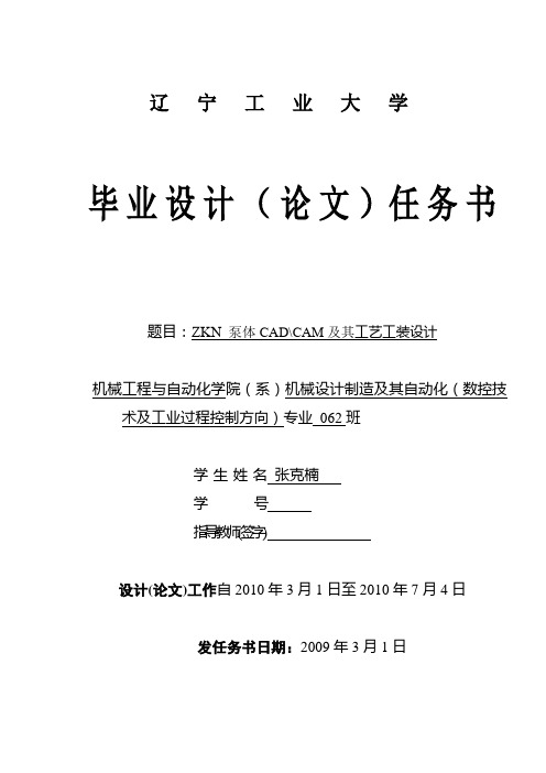
辽宁工业大学
毕业设计(论文)任务书
题目:ZKN泵体CAD\CAM及其工艺工装设计
机械工程与自动化学院(系)机械设计制造及其自动化(数控技术及工业过程控制方向)专业062班
学生姓名张克楠
学号
指导教师(签字)
设计(论文)工作自2010年3月1日至2010年7月4日
发任务书日期:2009年3月1日
任务书填写要求
3.任务书内填写的内容,必须和学生毕业设计(论文)完成的情况相一致,若有变更,应当经过所在专业及院(系)分管领导审批后方可重新填写;
4.任务书内有关“院(系)”、“专业”等名称的填写,应写中文全称,不能写数字代码。学生的“学号”要写全号,不能只写最后2位或1位数字;
5.任务书内“主要参考文献”的填写,应按照国标GB7714—87《文后参考文献著录规则》的要求书写,不能有随意性;
- 1、下载文档前请自行甄别文档内容的完整性,平台不提供额外的编辑、内容补充、找答案等附加服务。
- 2、"仅部分预览"的文档,不可在线预览部分如存在完整性等问题,可反馈申请退款(可完整预览的文档不适用该条件!)。
- 3、如文档侵犯您的权益,请联系客服反馈,我们会尽快为您处理(人工客服工作时间:9:00-18:30)。
摘要本毕业设计题目是阀堵工艺工装设计及CAD/CAM,来自岫岩××机械有限公司。
××公司专门从事国外机加工生产,主要的加工对象是阀体类零件,在精密铸造方面也有着他们自己的先进技术。
分析零件特点拟订合理的工艺规程,依据工艺规程设计,选择机床和设计合理的夹具。
设计内容:利用Pro/engineer的零件模块建造实体模型;利用CAXA电子图版绘制零件的工艺规程表和夹具设计图;利用MasterCAM模拟上表面各槽的加工路线和生成数控代码,利用CIMCO Edit对生成的数控代码进行仿真。
设计难点:在零件的工艺规程设计中,零件下表面粗糙度要求较高,通过精磨可以达到要求。
零件中心孔的粗糙度要求也较高,通过磨销即可达到要求。
零的专用铣刀完成。
零件下表件上表面0.38深圆槽较难加工,在加工中心用38.0面4.83宽圆槽也比较难加工,利用加工中心完成。
关键词:模具;夹具;模拟制造;实体造型AbstractThe subject of this design is designing the assembly and craft of valve base. It also relate to CAD/CAM. This subject task comes from Xiuyan ××Machinery CO.LTD which works in machining production for abroad. Its main machining objects are parts like types of valve base. It has advanced technology in investment casting.The feature of the parts is analyzed so as to plan the reasonable process and select the corresponding machine and inspection.Content of design: The parts module of the Pro/engineer is used to build the work piece. CAXA electric plate is used to draw the accessory's stipulation chart of technic and design of jig. MasterCAM is used to simulate the processing route of every trough of above surface and turn into the numerical control code. CIMCO Edit is used to carry on simulation to the numerical control code produced.Difficulties in design: In the simulation design of technic, low roughness is requested for the accessory's undersurface which can be achieved by carefully grinding. The roughness of the core bore should also be low, and it can be realized by grinding too. On the components the superficial 0.38 deep circular slot are difficult to process, and a special-purpose milling cutter is used in the machining center. The components undersurface 4.83 wide circular slots are also quite difficult to process, and it can be completed using the machining center.Key words:mould;jig;simulating manufacturing;physical model第1章绪论 (1)1.1 模具工业的概况 (1)1.2 我国模具工业现状 (1)1.3 我国模具工业的发展方向 (3)1.4 模具CAD/CAE/CAM发展概况及趋势 (3)第2章零件的三维造型 (6)2.1 零件的结构特征分析 (6)2.2 零件的三维造型过程 (6)2.3 零件三维造型的心得 (6)2.4 零件三维造型图片 (7)第3章阀座体的机械加工工艺规程设计 (8)3.1 阀座体工艺规程设计 (8)3.1.1 零件的结构工艺性分析 (8)3.1.2 计算生产纲领,确定生产类型 (8)3.1.3 毛坯种类及其制造方法的确定 (9)3.2 工艺路线的拟订 (9)3.2.1 定位基准的选择 (9)3.2.2 制定工艺路线 (9)3.2.3 选择加工设备及工艺装备 (11)3.3 切削用量和工时定额的确定 (11)3.3.1 基本计算公式的引用 (11)3.3.2各道工序的设计 (12)3.4 工艺合理性分析 (43)3.5 填写工艺卡片 (43)第4章机床专用夹具的设计 (44)4.1 机床专用夹具设计的基本要求 (44)4.2 钻床夹具Ⅰ的设计 (45)4.2.1 确定夹具类型 (45)4.2.2 拟定定位方案和选择定位元件 (45)4.2.3 夹具的整体结构设计 (45)4.2.4 夹紧力的分析 (45)4.2.5 夹具的使用说明 (46)4.3 钻床夹具Ⅱ的设计 (46)4.3.1 确定夹具类型 (46)4.3.2 拟定定位方案和选择定位元件 (46)4.3.3 夹具结构的整体设计 (46)4.3.4 夹紧力的分析 (46)4.3.5 夹具的使用说明 (47)4.4 钻床夹具Ⅲ的设计 (47)4.4.1 确定夹具类型 (47)4.4.2 拟定定位方案和选择定位元件 (47)4.4.3 夹具结构的整体设计 (47)4.4.4 夹紧力的分析 (47)4.4.5 夹具的使用说明 (47)4.5 钻床夹具Ⅳ的设计 (48)4.5.1 确定夹具类型 (48)4.5.2 拟定定位方案和选择定位元件 (48)4.5.3 夹具结构的整体设计 (48)4.5.4 夹紧力的分析 (48)4.5.5 夹具的使用说明 (48)4.6 立铣加工中心夹具Ⅰ的设计 (49)4.6.1 确定夹具类型 (49)4.6.2 拟定定位方案和选择定位元件 (49)4.6.3 夹具结构的整体设计 (49)4.6.4 夹紧力的分析 (49)4.6.5 夹具的使用说明 (49)4.7 立铣加工中心夹具Ⅱ的设计 (50)4.7.1 确定夹具类型 (50)4.7.2 拟定定位方案和选择定位元件 (50)4.7.3 夹具结构的整体设计 (50)4.7.4 夹紧力的分析 (50)4.7.5 夹具的使用说明 (50)第5章零件复杂表面的CAM设计 (51)5.1 计算机辅助制造(CAM)的介绍 (51)5.2 零件复杂表面CAM的设计过程 (51)5.3 MasterCAM加工仿真图片 (52)5.4 CIMCO Edit刀具轨迹模拟图片 (52)第6章结论 (53)参考文献 (54)致谢 (55)附录1钻床夹具Ⅰ装配图 (56)附录2钻床夹具Ⅱ装配图 (57)附录3钻床夹具Ⅲ装配图 (58)附录4钻床夹具Ⅳ装配图 (59)附录5立式加工中心夹具Ⅰ装配图 (60)附录6立式加工中心夹具Ⅱ装配图 (61)附录7英文资料及中文翻译 (62)第1章绪论1.1模具工业的概况模具是机械、汽车、电子、通讯、家电等工业产品的基础工艺装备之一。
作为工业基础,模具的质量、精度、寿命对其他工业的发展起着十分重要的作用,在国际上被称为“工业之母”,对国民经济发展起着不容质疑的作用。
模具工业是制造业中的一项基础产业,是技术成果转化的基础,同时本身又是高新技术产业的重要领域,在欧美等工业发达国家被称为“点铁成金”的“磁力工业”;美国工业界认为“模具工业是美国工业的基石”;德国则认为是所有工业中的“关键工业”;日本模具协会也认为“模具是促进社会繁荣富裕的动力”,同时也是“整个工业发展的秘密”,是“进入富裕社会的原动力”。
日本模具产业年产值达到13000亿日元,远远超过日本机床总产值9000亿日元。
如今,世界模具工业的发展甚至已超过了新兴的电子工业。
在模具工业的总产值中,冲压模具约占50%,塑料模具约占33%,压铸模具约占6%,其它各类模具约占11%。
在我国,随着国民经济的高速发展,模具工业的发展也十分迅速。
1999年中国大陆制造工业对模具的总市场需求量约为330亿元,今后几年仍将以每年10%以上的速度增长。
对于大型、精密、复杂、长寿命模具需求的增长将远超过每年10%的增幅。
汽车、摩托车行业的模具需求将占国内模具市场的一半左右。
1999年,国内汽车年产量为183万辆,保有量为1500万辆,预计到2005年汽车年产量将达600万辆。
仅汽车行业就将需要各种塑料件36万吨,而目前的生产能力仅为20多万吨,因此发展空间十分广阔。
家用电器,如彩电、冰箱、洗衣机、空调等,在国内的市场很大。
目前,我国的彩电的年产量已超过3200万台,电冰箱、洗衣机和空调的年产量均超过了100万台。
家用电器行业的飞速发展使之对模具的需求量极大。
到2010年,在建筑与建材行业方面,塑料门窗的普及率为30%,塑料管的普及率将达到50%,这些都会大大增加对模具的需求量。
其它发展较快的行业,如电子、通讯和建筑材料等行业对模具的需求,都将对中国模具工业和技术的发展产生巨大的推动作用。
1.2我国模具工业现状我国模具工业起步晚、底子薄,与工业发达国家相比有很大的差距,但在国家产业政策和与之配套的一系列国家经济政策的支持和引导下,我国模具工业发展迅速。
据统计,我国现有模具生产厂近2万家,从业人员约50万人,“九五”期间的年增长率为13%,2000年总产值为270亿元,占世界总量的5%。
但从总体上看,自产自用占主导地位,商品化模具仅为1/3左右,国内模具生产仍供不应求,特别是精密、大型、复杂、长寿命模具,仍主要依赖进口。
目前,就整个模具市场来看,进口模具约占市场总量的20%左右,其中,中高档模具进口比例达40%以上。
