华新科技电阻资料
电子元器件品牌明细表
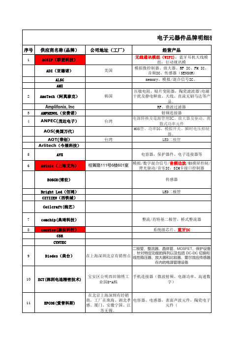
26
KEMET(基美)
苏州
坦电容
27
Kyocera(京瓷)
东莞
电容(陶瓷/钽/电解等)、晶体、晶体振荡 器、声表面波谐振器、芯片电阻、晶体滤波 器、蓝牙TM射频模块、天线开关模块、光学
器件、SAW等。
28
LCN(德国宜森)
系统连接器,藕合器,总线模块
29
LETCON(深圳信为通电子)
深圳市宝安区石岩洲石路 梨园科技园B,C栋
70
嘉富盛
宝安区大浪街道浪口社区 华明路仪佳扬工业园2栋1
楼3楼
端子、接插件 音频、视频连接器 器 音频、视频插座
手机连接
71
江苏长电科技
二极管、三极管、晶闸管、场效应管、稳压 电路等。
72
杰顺通
昆山市玉山镇紫竹路1389 电池/SIM卡连接器,I/O,摄像头插座,
号
储存卡
73
启攀微
宜山路1618号D栋4楼
管
47
SUMSUNG(三星)
静/动态随机存取存储器,flash,等
48 Sunlord(顺络电子)
深圳
电感、热敏电阻、LC滤波器共模抑制器、 EMC元器件、RF元件、电路保护器件等。
49
SuperPix(视信源集团)
北京市海淀区上地五街七 号昊海大厦201-202室
CMOS摄像芯片
Taitien(泰艺)
LED灯
深圳市南山区高新技术产
15
Eyang(宇阳)
业园北区朗山二号路齐民
道3号
片式多层陶瓷电容器
16 Fairchild(飞兆半导体)
藕合器、MOS管、二极管、整流器等
浦东新区 张江高科技园区
国内外常用电子元器件型号命名规则比如:电阻器,电容器
(5)日本松下旗下三洋电机(Panasonic)
(6)韩国三星(SAMSUNG)
(7)美国基美(KEMET)
(8)英国Syfer
(9)中国台湾国巨(YAGEO)
(10)中国台湾华新科技(WALSIN)
3.电感器
4.变压器
5.二极管
6.三极管
7.发光二极管
8.扬声器
9.电声器件
10晶闸管
11.继电器
国外:
1.国际电子联合会半导体器件命名法
国际电子联合会晶体管型号命名法的特点:
1)这种命名法被欧洲许多国家采用。因此,凡型号以两个字母开头,并且第一个字母是A,B,C,D或R的晶体管,大都是欧洲制造的产品,或是按欧洲某一厂家专利生产的产品。
2)第一个字母表示材料(A表示锗管,B表示硅管),但不表示极性(NPN型或PNP型)。
3)第二个字母表示器件的类别和主要特点。如C表示低频小功率管,D表示低频大功率管,F表示高频小功率管,L表示高频大功率管等等。若记住了这些字母的意义,不查手册也可以判断出类别。例如,BL49型,一见便知是硅大功率专用三极管。
4)第三部分表示登记顺序号。三位数字者为通用品;一个字母加两位数字者为专用品,顺序号相邻的两个型号的特性可能相差很大。例如,AC184为PNP型,而AC185则为NPN型。
8)日本通常把Pcm≥1W的管子,称做大功率管。
5)第四部分字母表示同一型号的某一参数(如hFE或NF)进行分档。
6)型号中的符号均不反映器件的极性(指NPN或PNP)。极性的确定需查阅手册或测量。
2.美国半导体器件型号命名法
美国晶体管或其它半导体器件的型号命名法较混乱。这里介绍的是美国晶体管标准型号命名法,即美国电子工业协会(EIA)规定的晶体管分立器件型号的命名法。如下表:
NTC - CN0603R103B3435HB
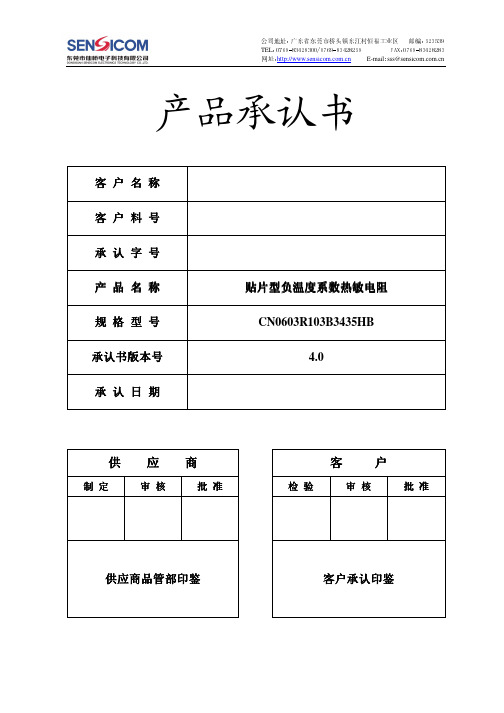
第 1 页(共 8 页)
版本:4.0
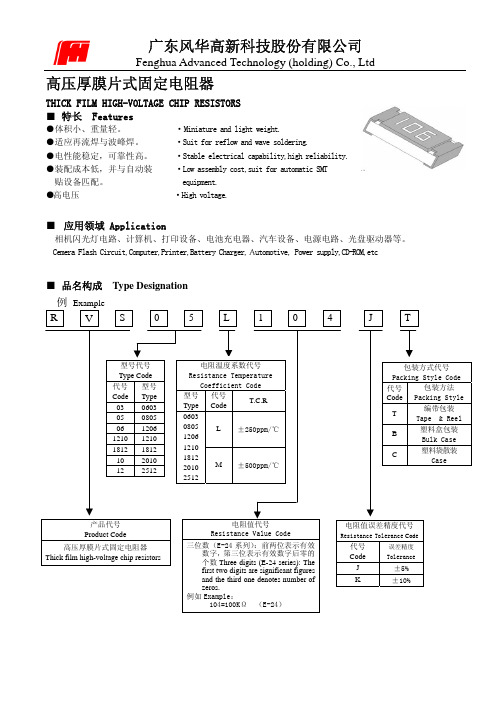
1、 规格型号
公司地址:广东省东莞市桥头镇东江村恒福工业区 邮编:523539
T网E址L::0h7tt6p9:-//8w3w42w8.s3e0n0s/ic0o7m69.c-o8m34.c2n8259
FAX:0769-83428283 : E-mail sss@
环境温度:25±2℃; 工作电流 周期:6000
无外观损伤 ∣△ ∣≤ R25/ R25 5% ∣△B/ B∣≤2%
4、 包装、贮存
4.1 包装
序号 包装方式 (1) 编带 (2) 内包装盒 (3) 外包装箱
包装材料、尺寸 0603 纸带,标准带轮 纸箱,L×W×H=185mm×70mm×190mm 纸箱,L×W×H=370mm×205mm×215mm
RMin(KΩ) 201.5613 190.0997 179.3741 169.3323 159.9259 151.1105 142.8448 135.0908 127.8135 120.9802 114.5610 108.5280 102.8553 97.5191 92.4971 87.7689 83.3153 79.1185 75.1621 71.4308 67.9103 64.5873 61.4495 58.4854 55.6843 53.0362 50.5317 48.1622 45.9196 43.7962 41.7850 39.8794 38.0731 36.3605 34.7360 33.1946 31.7315 30.3423 29.0228
T网E址L::0h7tt6p9:-//8w3w42w8.s3e0n0s/ic0o7m69.c-o8m34.c2n8259
FAX:0769-83428283 : E-mail sss@
Faq-020304CST中3种微带薄膜电阻的设置

前处理|材料属性 1 Faq-020304: CST 中的3种微带薄膜电阻的设置CST 中设置微带薄膜电阻分为3种情况:1) 微带线有厚度,趋肤深度远大于带线厚度;2) 微带线有厚度,趋肤深度与带线厚度可比拟;3) 微带线为零厚度。
以下左图为1)、2)情况,右图为3)情况。
如上图所示,在两微带线之间新建一个Brick 方块并定义其材料作为微带薄膜电阻,以下是3种情况下各自材料的定义方法。
1. 有厚度材料,材料属性设为Normal这种设置适用于微带线有厚度,趋肤深度远大于带线厚度的情况,如下图所示:上图中W 、L 、t 分别为微带薄膜电阻的截面宽度、电阻长度和截面厚度。
其电阻值为L L R Wt Wtρσ==,其中ρ为电阻率,σ为电导率。
有L RWtσ=。
如下图所示,新建的电阻材料Resistor 材料设置对话框中材料类型选用Normal ,Conductivity 选项卡中电导率设为L/(R*W*t),这里采用参量设置,另需要设置L 、R 、W 、t 四参量的值。
其中R 即为所希望电阻值。
2CST 工作室套装™–常见问题解答FAQs2.有厚度材料,材料属性设为Lossy metal 这种设置适用于工作频率较高,良导体微带线有一定厚度,但趋肤深度与带线厚度可比拟的情况。
此时材料类型选用Lossy metal 。
如下图所示,电导率同样设为L/(R*W*t)。
R 即为所希望的电阻值。
这种设置另适用于电阻值较小的情况。
当电阻值较大,材料属性与损耗金属特性相去甚远,则还是推荐使用第一种设置方法。
3. 零厚度材料,材料属性设为Ohmic Sheet这种设置适用于带线采用零厚度的情况,如下图所示: 材料用Normal设电导率前处理|材料属性 3其中W 、L 分别为电阻材料的截面宽度和长度。
材料类型选用Ohmic Sheet ,此时需要设置面电阻值s RWR L =,如下图所示:注意:这种方法仅能用于频域有限元求解器。
贴片元件常见封装

贴片电阻常见封装有9种,用两种尺寸代码来表示。
一种尺寸代码是由4位数字表示的EIA(美国电子工业协会)代码,前两位与后两位分别表示电阻的长与宽,以英寸为单位。
我们常说的0603封装就是指英制代码。
另一种是米制代码,也由4位数字表示,其单位为毫米。
下表列出贴片电阻封装英制和公制的关系及详细的尺寸:一、零件规格:(a)、零件规格即零件的外形尺寸,SMT发展至今,业界为方便作业,已经形成了一个标准零件系列,各家零件供货商皆是按这一标准制造。
标准零件之尺寸规格有英制与公制两种表示方法,如下表英制表示法1206 0805 0603 0402公制表示法3216 2125 1608 1005含义L:1.2inch(3.2mm)W:0.6inch(1.6mm)L:0.8inch(2.0mm)W:0.5inch(1.25mm)L:0.6inch(1.6mm)W:0.3inch(0.8mm)L:0.4inch(1.0mm)W:0.2inch(0.5mm)注:a、L(Length):长度;W(Width):宽度;inch:英寸b、1inch=25.4mm(b)、在(1)中未提及零件的厚度,在这一点上因零件不同而有所差异,在生产时应以实际量测为准。
(c)、以上所讲的主要是针对电子产品中用量最大的电阻(排阻)和电容(排容),其它如电感、二极管、晶体管等等因用量较小,且形状也多种多样,在此不作讨论。
(d)、SMT发展至今,随着电子产品集成度的不断提高,标准零件逐步向微型化发展,如今最小的标准零件已经到了0201。
二、常用元件封装1)电阻:最为常见的有0805、0603两类,不同的是,它可以以排阻的身份出现,四位、八位都有,具体封装样式可参照MD16仿真版,也可以到设计所内部PCB库查询。
注:ABCD四类型的封装形式则为其具体尺寸,标注形式为L X S X H 1210具体尺寸与电解电容B类3528类型相同0805具体尺寸:2.0 X 1.25 X 0.5(公制表示法)1206具体尺寸:3.0 X 1.5 0X 0.5(公制表示法)2)电阻的命名方法1、5%精度的命名:RS – 05 K 102 JT2、1%精度的命名:RS – 05 K 1002 FTR -表示电阻S -表示功率0402是1/16W、0603是1/10W、0805是1/8W、1206是1/4W、1210是1/3W、1812是1/2W、2010是3/4W、2512是1W。
全球知名MLCC的供应商有哪些?
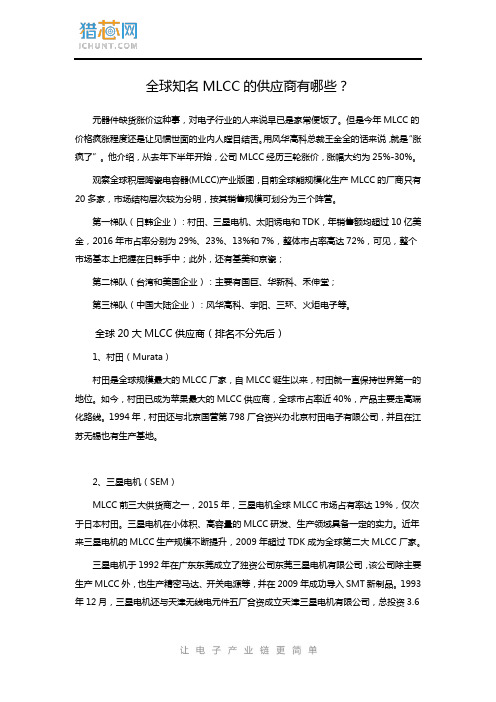
全球知名MLCC的供应商有哪些?元器件缺货涨价这种事,对电子行业的人来说早已是家常便饭了。
但是今年MLCC的价格疯涨程度还是让见惯世面的业内人瞠目结舌。
用风华高科总裁王金全的话来说,就是“涨疯了”。
他介绍,从去年下半年开始,公司MLCC经历三轮涨价,涨幅大约为25%-30%。
观察全球积层陶瓷电容器(MLCC)产业版图,目前全球能规模化生产MLCC的厂商只有20多家,市场结构层次较为分明,按其销售规模可划分为三个阵营。
第一梯队(日韩企业):村田、三星电机、太阳诱电和TDK,年销售额均超过10亿美金,2016年市占率分别为29%、23%、13%和7%,整体市占率高达72%,可见,整个市场基本上把握在日韩手中;此外,还有基美和京瓷;第二梯队(台湾和美国企业):主要有国巨、华新科、禾伸堂;第三梯队(中国大陆企业):风华高科、宇阳、三环、火炬电子等。
全球20大MLCC供应商(排名不分先后)1、村田(Murata)村田是全球规模最大的MLCC厂家,自MLCC诞生以来,村田就一直保持世界第一的地位。
如今,村田已成为苹果最大的MLCC供应商,全球市占率近40%,产品主要走高端化路线。
1994年,村田还与北京国营第798厂合资兴办北京村田电子有限公司,并且在江苏无锡也有生产基地。
2、三星电机(SEM)MLCC前三大供货商之一,2015年,三星电机全球MLCC市场占有率达19%,仅次于日本村田。
三星电机在小体积、高容量的MLCC研发、生产领域具备一定的实力。
近年来三星电机的MLCC生产规模不断提升,2009年超过TDK成为全球第二大MLCC厂家。
三星电机于1992年在广东东莞成立了独资公司东莞三星电机有限公司,该公司除主要生产MLCC外,也生产精密马达、开关电源等,并在2009年成功导入SMT新制品。
1993年12月,三星电机还与天津无线电元件五厂合资成立天津三星电机有限公司,总投资3.6亿美元,主要生产MLCC、IC基板、高密度互联板、精密电机、图像传感器等数码产品核心部件。
电感厂商参考
12、奇力新电子股份有限公司(Chilisin)
总部:台湾 主营:电感元件专业制造与服务供应商。 官网:/ 13、西北台庆科技股份有限公司(Tai-tech)
主营:共模磁环电感,工字带磁屏蔽电感,UU9.8、UU10.5 滤波器, 工字电感,磁棒电感,空心线圈。 官网:/ 43、深圳市引领者科技有限公司(香港佳器实业有限公司) 总部:深圳 主营:专业设计、生产、销售为一体的各类电感器、电子变压器、 工字电感、滤波器及线圈类产品。 官网:/ 44、无锡市锦云电感器有限公司
主营:专业生产片式多层陶瓷电容器(MLCC);HIC 和片式电阻用 氧化铝陶瓷基片,光纤连接器陶瓷插芯,微波介质陶瓷器件,塑封 片式电感器,各种膜类固定电阻器,电阻陶瓷基体等电子元器件。 官网:/ 26、东莞市宇顺塑胶电子有限公司
总部:东莞 主营:绕线电感,一体成型 SMD 电感,大电流功率电感、大功率电 感,SMD 功率电感、扁平线圈电感,组装式大电流电 感, CPU CHOKE,POWER CHOKE,模压线圈、模压电感、可调电感、片式电感、 片式磁珠、贴片中周、空芯线圈等。 官网: 27、深圳市迈翔科技有限公司
总部:深圳 主营:插件及贴片功率电感、大电流功率电感。 官网: 28、深圳市研科达电子有限公司
总部:深圳 主营:SMD 功率电感、片式电感、片式磁珠、贴片中周、扼流线圈、 空芯线圈、立式电感、模压线圈、可调电感等。 官网: 29、深圳市安瑞科电子有限公司
电感基本常识介绍 基本作用:滤波、振荡、延迟、陷波等。 形象说法:“通直流,阻交流” 细化解说:在电子线路中,电感线圈对交流有限流作用,它与电阻器或电容器能 组成高通或低通滤波器、移相电路及谐振电路等;变压器可以进行交流耦合、变 压、变流和阻抗变换等。 电感线圈也是一个储能元件,它以磁的形式储存电能,储存的电能大小可用下式 表示:WL=1/2 Li2 。可见,线圈电感量越大,流过越大,储存的电能也就越多。 电感在电路最常见的作用就是与电容一起,组成 LC 滤波电路。
风华电阻
额定负荷百分比 Percent rated load
-75 -50 -25
0
25 50 75 100 125 155
环境温度 Ambient temperature (℃)
当电阻使用的环境温度超过 70℃时,其额定负荷(额定功率或额定电流)按上述曲线下降。 For resistors operated in ambient over 70℃,rated load (power rating or current rating) shall be derated in accordance with the above figure.
最大过负荷电压(V) Max.Overload Voltage
1/10W 1/8W 1/4W 1/3W 1/2W 3/4W 1W
300
400 500 600 700 800 1000
600
800 1000 1200 1400 1600 2000
电阻温度系数 Resistance Temperature
Coefficient Code
型号 代号 Type Code
T.C.R
0603
0805 L ±250ppm/℃ 1206
1210
1812 2010 M ±500ppm/℃
2512
包装方式代号
Packing Style Code
代号
包装方法
Code Packing Style
编带包装
T
Tape & Reel
■ 特性 Characteristics
项目 Item
端头强度
Bending Strength
电阻温度系数 T.C.R
电阻基础知识学习资料

贴片电阻资料大全简述:我们常说的贴片电阻(SMD Resistor)学名叫:片式固定电阻器,是从Chip Fixed Resistor直接翻译过来的。
特点是耐潮湿,耐高温,可靠度高,外观尺寸均匀,精确且温度系数与阻值公差小。
按生产工艺分厚膜(Thick Film Chip Resistors)、薄膜(Thin Film Chip Resistors)两种。
厚膜是采用丝网印刷将电阻性材料淀积在绝缘基体(例如玻璃或氧化铝陶瓷)上,然后烧结形成的。
我们通常所见的多为厚膜片式电阻,精度范围±0.5% ~ 10%,温度系数:±50PPM/℃~ ±400PPM/℃。
薄膜是在真空中采用蒸发和溅射等工艺将电阻性材料淀积在绝缘基体工艺(真空镀膜技术)制成,特点是低温度系数(±5PPM/℃),高精度(±0.01%~±1%)。
封装有:0201,0402,0603,0805,1206,1210,1812,2010,2512。
其常规系列的精度为5%,1%。
阻值范围从0.1欧姆到20M欧姆。
标准阻值有E24,E96系列。
功率有1/20W、1/16W、1/8W、1/10W、1/4W、1/2W、1W。
特性:∙体积小,重量轻∙适合波峰焊和回流焊∙机械强度高,高频特性优越∙常用规格价格比传统的引线电阻还便宜∙生产成本低,配合自动贴片机,适合现代电子产品规模化生产使用状况:由于价格便宜,生产方便,能大面积减少PCB面积,减少产品外观尺寸,现在已取代绝大部分传统引线电阻。
除一些小厂或不得不使用引线电阻的设计,各种电器上几乎都在使用。
目前绝大部分电子产品,以0603、0805器件为主;以手机,PDA为代表的高密度电子产品多使用0201、0402的器件;一些要求稳定和安全的电子产品,如医疗器械、汽车行驶记录仪、税控机则多采用1206、1210等尺寸偏大的电阻。
市场状况:目前,在全球的市场份额中,排名依次是台湾、日本、中国、韩国,欧美几乎不再生产。
全球25家MLCC品牌及其代理商明细汇总
汇总|全球25家MLCC品牌及其代理商明细MLCC是片式多层陶瓷电容器英文缩写.(Multi-layerceramiccapacitors)1940年前后人们发现了现在的陶瓷电容器的主要原材料BaTiO3(钛酸钡)具有绝缘性后,开始将陶瓷电容器使用于对既小型、精度要求又极高的军事用电子设备当中。
而多层陶瓷电容器于1960年左右作为商品开始开发。
到了1970年,随着混合IC、计算机、以及便携电子设备的进步也随之迅速的发展起来,成为电子设备中不可缺少的零部件。
现在的陶瓷介质电容器的全部数量约占电容器市场的70%左右。
下面易容网就为大家盘点全球常用的MLCC的制造商和MLCC各大品牌的代理商(排名不分先后)1.村田制作所国家:日本英文名:MURATA 中文名:村田村田制作所是日本一家电子零件专业制造厂,其总部设于京都府长冈京市。
该公司于1944年10月创业,1950年12月正式改名为村田制作所。
创业者是村田昭主力商品是陶瓷电容器,高居世界首位。
其他具领导地位的零件产品计有陶瓷滤波器,高频零件,感应器等。
村田制作所是全球领先的电子元器件制造商。
村田制作所的客户分布在PC、手机、汽车电子等领域。
随着消费电子领域竞争的不断加剧,产品更新换代的速度不断加快,而作为上游电子元器件供应商,能够随时了解客户需求,甚至走在客户之前开发出更新产品,成为村田制作所业务持续增长的关键。
不断推出新产品是村田制作所的竞争力源泉,而不断推出市场需要的产品则是其业绩保持增长的保障。
代理商目录(排名不分先后)深圳仁天芯科技有限公司深圳市湘海电子有限公司雅创电子零件有限公司帕太国际贸易(上海)有限公司深圳市怡海能达科技发展有限公司首科科技(深圳)有限公司威雅利电子(上海)有限公司香港雅创台信电子有限公司深圳市健三实业有限公司上海庆翌电子有限公司苏州欣村电子有限公司天津通慧阳国际贸易有限公司上海旭沁电子科技有限公司深圳市威欣睿电子有限公司深圳庆美达电子有限公司深圳市奇林实业有限公司深圳市水泽田科技有限公司深圳市赣龙科技发展有限公司深圳市鼎芯无限科技有限公司深圳市顺百科技有限公司深圳市长天电子科技有限公司苏州明贝电子有限公司深圳市兴又昌科技有限公司2.TDK株式会社国家:日本英文名:TDK 中文名:TDKTDK是一个著名的电子工业品牌,一直在电子原材料及元器件上占有领导地位。
北京华新电工专变采集终端说明书V1.3
3
电源 交采 模块
12V 8V 交采 (串口)
核心处 理模块
RS485
串口 控制
通讯 模块
串口
接口模块
图 2 终端功能模块结构图 2.2.1 核心处理模块 终端核心处理模块使用 AT91SAM9200 处理器,对外提供 8 各通讯串口、6 个按键、一个 USB 接口、12 个指示灯及一块 160*160 的 LCD 点阵显示器。 串口分派如下:UART0 用于 GPRS 通讯; UART1 用于本地 232 通讯; UART2 用于 RS485 抄表口 1 通讯; UART3 用于 RS485 抄表口 2 通讯; UART4 用于红外通讯; UART5 用于和交采模块通讯; DEBUG 口用于和接口模块通讯。 2.2.2 电源交采模块 电源交采模块由电源部分和交采部分组成, 电源部分使用开关电源实现 AC-DC 转换, 电 源共有三组直流电压输出:一组+8V、一组+12V、一组+5V,其中+8V 用于为主系统提供电源 支持,+12V 用于为接口模块提供电源支持,+5V 用于为交采模块提供电源支持,三组电源相 互隔离。 交采模块由交流采集专用芯片、交采 MCU 及存储器等相关其器件组成,主要负责采集 3 相电压与电流信号(含零序采集)及相关项的谐波数据采集,同时也负责检测 CT 开路、短 路。 2.2.3 通讯模块 终端通讯模块与核心处理模块之间通过串口通讯, 通讯模块负责将终端的数据发送到网 络或将网络的数据接收到终端, 核心处理模块对相应的数据进行处理。 通讯模块的电源由核 心处理模块控制, 当通讯模块出现异常时核心处理模块可以通过复位其电源实现对通讯模块 的重启。
2、
终端结构与原理
2.1 终端外形结构
电阻 电容的品牌大全交流问答
电子元器件基础知识--电阻电容的品牌大全1、请列举您知道的电阻、电容、电感品牌(最好包括国内、国外品牌)。
电阻:美国:AVX、VISHAY威世日本:KOA兴亚、Kyocera京瓷、muRata村田、Panasonic 松下、ROHM罗姆、susumu、TDK台湾: LIZ丽智、PHYCOM飞元、RALEC旺诠、ROYALOHM厚生、SUPEROHM美隆、TA-I大毅、TMTEC泰铭、TOKEN德键、TYOHM幸亚、UniOhm厚声、VITROHM、VIKING 光颉、WALSIN华新科、YAGEO国巨新加坡:ASJ 中国:FH风华、捷比信电容:美国:AVX、KEMET基美、Skywell泽天、VISHAY威世英国:NOVER诺华德国:EPCOS、WIMA威马丹麦:JENSEN战神日本:ELNA伊娜、FUJITSU富士通、HITACHI日立、KOA兴亚、Kyocera京瓷、Matsushita松下、muRata村田、NEC、nichicon(蓝宝石)尼吉康、Nippon Chemi-Con(黑金刚、嘉美工)日本化工、Panasonic松下、Raycon威康、Rubycon(红宝石)、SANYO三洋、TAIYO YUDEN太诱、TDK、TK东信韩国:SAMSUNG三星、SAMWHA 三和、SAMYOUNG三莹台湾:CAPSUN、CAPXON(丰宾)凯普松、Chocon、Choyo、ELITE金山、EVERCON、EYANG宇阳、GEMCON至美、GSC杰商、G-Luxon世昕、HEC 禾伸堂、HERMEI合美电机、JACKCON融欣、JPCON正邦、LELON立隆、LTEC辉城、OST奥斯特、SACON士康、SUSCON 冠佐、TAICON台康、TEAPO智宝、WALSIN华新科、YAGEO国巨香港:FUJICON富之光、SAMXON万裕中国:AiSHi 艾华科技、Chang常州华威电子、FCON深圳金富康、FH广东风华、HEC东阳光、JIANGHAI南通江海、JICON吉光电子、LM佛山利明、R.M佛山三水日明电子、Rukycon海丰三力、Sancon海门三鑫、SEACON深圳鑫龙茂电子、SHENGDA扬州升达、TAI-TECH台庆、TF南通同飞、TEAMYOUNG天扬、QIFA奇发电子电感:美国:AEM、AVX、Coilcraft线艺、Pulse普思、VISHAY威世德国:EPCOS、WE 日本:KOA兴亚、muRata村田、Panasonic松下、sumida胜美达、TAIYO YUDEN 太诱、TDK、TOKO、TOREX特瑞仕台湾:CHILISIN奇力新、yers美磊、TAI-TECH台庆、TOKEN德键、VIKING光颉、WALSIN华新科、YAGEO国巨中国:Gausstek丰晶、GLE格莱尔、FH风华、CODACA科达嘉、Sunlord顺络、紫泰荆、肇庆英达2、请解释电阻、电容、电感封装的含义:0402、0603、0805。
华新电阻规格书

Functional code X : Thick film low ohm M : Metal low ohm N : Metal low ohm, high power W : Thick film low TCR P : Thick film low TCR high power ( 2512 size=2 watt, 2010 size=1 watt, 1210 size=0.5 watt, 1206 size=0.5 watt,
R002
Tolerance F : +/- 1% J : +/- 5% P : Jumper
Packaging code P : 4” reel taping T : 7” reel taping A : 7” reel taping 15Kpcs Q : 10” reel taping G : 13” reel taping R : 0603 2mm pitch taping B : Bulk K : Bulkcase
Termination code L = Sn base (Lead free) 5 3E SSP (total)
WW
25
M
F
T
L
Type code WW: R< 1ohm MW: R< 1ohm Automotive SW: R< 1ohm Anti-sulfuration
Size code 25 : 2512 (6432) 20 : 2010 (5025) 18 : 1218 (3248) 12 : 1206 (3216) 10 : 1210 (3225) 08 : 0805 (2012) 06 : 0603 (1608) 04 : 0402 (1005)
WALSIN华新科电阻

WR02X(W)±5%, ±1%Thick Film General purpose chip resistors Size 0201*Contents in this sheet are subject to change without prior notice.FEATURE1. Small size and light weight2. High reliability and stability3. Reduced size of final equipment4. Suitable for high density print circuit board assembly5. Higher component and equipment reliability6. Lead free productAPPLICATION•Mobile phone•PDA•Camcorders•Palmtop computers•Hybrid moduleDESCRIPTIONThe resistors are constructed in a high grade ceramic body (aluminum oxide). Internal metal electrodes are added at each end and connected by a resistive paste that is applied to the top surface of the substrate. The composition of the paste is adjusted to give the approximate resistance required and the value is trimmed to nominated value within tolerance which controlled by laser trimming of this resistive layer.The resistive layer is covered with a protective coat. Finally, the two external end terminations are added. For ease of soldering the outer layer of these end terminations is a pure Tin.Fig 1. Construction of Chip-R WR02XQUICK REFERENCE DATAItem General Specification Series No. WR02X(W)Size code 0201(0603) Resistance Range 1Ω~10MΩ ( ±5% tolerance ), Jumper1Ω~ 10MΩ ( ±1% tolerance )Resistance Tolerance ±1%E96/E24 ±5% E24TCR (ppm/°C) 10Ω - 10MΩ, ≤±2001 - 9.76Ω, +600~-200Max. dissipation @ T amb=70°C 1/20 WMax. Operation Voltage (DC or RMS) 25VMax. Overload Voltage (DC or RMS) 50VOperation temperature -55 ~ +125’CNote :1. This is the maximum voltage that may be continuously supplied to the resistor element, see “IEC publication60115-8”2. Max. Operation Voltage : So called RCWV (Rated Continuous Working Voltage) is determined byValueResistancePowerRatedRCWV×=or Max. RCWV listed above, whichever is lower. DIMENSION(unit : mm)WR02X(W)L 0.60 ± 0.03W 0.30 ± 0.03T 0.23 ± 0.03Tb 0.15 ± 0.05Tt 0.10 ± 0.05MARKINGWR02X(W) has no marking.FUNCTIONAL DESCRIPTIONProduct characterizationStandard values of nominal resistance are taken from the E24/E96 series for resistors with a tolerance of ±5% & ±1%. The values of the E24/E96 series are in accordance with “IEC publication 60063”DeratingThe power that the resistor can dissipate depends on the operating temperature; see Fig.2Figure 2. Maximum dissipation in percentage of rated powerAs a function of the ambient temperatureMOUNTINGDue to their rectangular shapes and small tolerances, Surface Mountable Resistors are suitable for handling by automatic placement systems.Chip placement can be on ceramic substrates and printed-circuit boards (PCBs).Electrical connection to the circuit is by individual soldering condition.The end terminations guarantee a reliable contact.SOLDERING CONDITIONThe robust construction of chip resistors allows them tobe completely immersed in a solder bath of 260°C for 10seconds. Therefore, it is possible to mount SurfaceMount Resistors on one side of a PCB and otherdiscrete components on the reverse (mixed PCBs).Surface Mount Resistors are tested for solderability at235°C during 2 seconds. The test condition for noleaching is 260°C for 30 seconds. Typical examples ofsoldering processes that provide reliable joints withoutany damage are given in Fig 3.Fig 3. Infrared soldering profile for Chip Resistors WR02X(W)CATALOGUE NUMBERSThe resistors have a catalogue number starting with :WR02 X 472_ J A LSize codeWR02 : 0201 Type codeX: NormalW : 1% For <10Ω and>1MΩResistance code5%, E24: 2 significant digitsfollowed by no. ofzeros and a blank4.7Ω = 4R7_100Ω = 101_10KΩ = 103_1%, E24+E96: 3 significantdigits followed by no.of zeros100Ω=100037.4KΩ=3742ToleranceJ : ±5%F : ±1%P : JumperPackaging codeA: 7” Reeled taping(15Kpcs/Reel)T: 7” Reeled taping(10Kpcs/Reel)D: 7” Reeled taping(20Kpcs/Reel)H : 13” Reeled taping(50Kpcs/Reel)G : 13” Reeled taping(70Kpcs/Reel)Termination codeL= Sn base (leadfree)TEST CONDITION FOR JUMPER (0 Ω)Item WR02Power Rating At 70°C 1/20WResistance MAX.50mΩ Rated Current 1APeak Current within 5 sec 2.5AOperating Temperature -55 ~ +125°CTEST AND REQUIREMENTS (JIS C 5201-1 : 1998)PACKAGINGPaper Tape specifications (unit :mm)Series No. A B W F E WR02X0.67±0.050.37±0.058.00±0.203.50±0.051.75±0.10Series No. P1 P0 ΦDTWR02X2.00±0.054.00±0.051.00.050.1+−Φ0.45±0.05Reel dimensionsSymbol A B C D 7” Reel Φ178.0±0.2 Φ60.0±1.0 13.0±0.2 9.0±0.5 10” Reel Φ254.0±2.0 Φ100.0±1.0 13.0±0.2 9.0±0.5 13” ReelΦ330.0±2.0Φ100.0±1.013.0±0.29.0±0.5Taping quantity and Tape material- Chip resistors 10,000 / 15,000 / 20,000 pcs 7” Reel, Paper tape. - Chip resistors 50,000 / 70,000 pcs 13” Reel, Paper tape.WR12, WR08, WR06, WR04±1%, ±5%Thick Film General Purpose Chip Resistors Size 1206, 0805, 0603, 0402RoHS 2 compliant & Halogen free*Contents in this sheet are subject to change without prior notice.FEATURE1. High reliability and stability2. Reduced size of final equipment3. Lower assembly costs4. Higher component and equipment reliability5. RoHS 2 compliant and Halogen free productsAPPLICATION∙Consumer electrical equipment∙EDP, Computer application∙Telecom applicationDESCRIPTIONThe resistors are constructed in a high grade ceramic body (aluminum oxide). Internal metal electrodes are added at each end and connected by a resistive paste that is applied to the top surface of the substrate. The composition of the paste is adjusted to give the approximate resistance required and the value is trimmed to within tolerance by laser cutting of this resistive layer.The resistive layer is covered with a protective coat. Finally, the two external end terminations are added. For ease of soldering the outer layer of these end terminations is a Tin (lead free) alloy.Fig 1. Construction of Chip-RQUICK REFERENCE DATANote :1. This is the maximum voltage that may be continuously supplied to the resistor e lement, see “IEC publication60115-8”2. Max. Operation Voltage : So called RCWV (Rated Continuous Working Voltage) is determined byValueRes is tancePowerRatedRCWV⨯=or Max. RCWV listed above, whichever is lower.3. The resistance of Jumper is defined <0.05Ω.DIMENSIONS (unit : mm)MARKING3-digits marking(±5% : 1206 & 0805 & 0603 )Each resistor is marked with a three digits code on the protective coating to designate the nominal resistance value. 3-digits marking(±1% : 0603)4-digits marking(±1% : 1206/0805)Each resistor is marked with a four digits code on the protective coating to designate the nominal resistance value. ExampleFUNCTIONAL DESCRIPTIONProduct characterizationStandard values of nominal resistance are taken from the E24 series for resistors with a tolerance of ±5%, and E96 series for resistors with a tolerance of ±1%. The values of the E24/E96 series are in accordance with “IEC publication 60063”DeratingThe power that the resistor can dissipate depends on the operating temperature; see Fig.2Figure 2Maximum dissipation in percentage of rated power as afunction of the ambient temperature for WR12, WR08,WR06, WR04MOUNTINGDue to their rectangular shapes and small tolerances, Surface Mountable Resistors are suitable for handling by automatic placement systems.Chip placement can be on ceramic substrates and printed-circuit boards (PCBs).Electrical connection to the circuit is by individual soldering condition.Storage and Handling Conditions:1. Products are recommended to be used up within two years since operation date as ensured shelf life. Check solderability in case shelf life extension is needed.2. To store products with following condition:Temperature :5 to 40℃Humidity :20 to 70% relative humidity3. Caution:a.Don't store products in a corrosive environment such as sulfide, chloride gas, or acid.It may cause oxdization of electrode, which easily be resulted in poor solderingb.To store products on the shelf and avoid exposure to moisture.c.Don't expose products to excessive shock, vibration, direct sunlight and so onSOLDERING CONDITION follows J-STD-020DThe robust construction of chip resistors allows them to be completely immersed in a solder bath of 260︒C for 10 seconds. Therefore, it is possible to mount Surface Mount Resistors on one side of a PCB and other discrete components on the reverse (mixed PCBs).Surface Mount Resistors are tested for solderability at 235︒C during 2 seconds. The test condition for no leaching is 260︒C for 30 seconds. Typical examples of soldering processes that provide reliable joints withoutany damage are given in Fig 3.CATALOGUE NUMBERSThe resistors have a catalogue number starting withWR12, WR08, WR06:1. Reeled tape packaging : 8mm width paper taping 5000pcs per 7” reel, 10kpcs per 10” reel, 20kpcs per 13” reel.2. Bulk packaging : 5000pcs per poly-bagWR04:1. Reeled tape packaging : 8mm width paper taping 10,000pcs per 7” reel, 20,000pcs per 10” reel. 70,000pcs per 13”reel.2. Bulk packaging : 10,000pcs per poly-bagTEST AND REQUIREMENTSEssentially all tests are carried out according to the schedule of IEC publication 115-8, category LCT /UCT /56(rated temperature range : L ower C ategory T emperature, U pper C ategory T emperature; damp heat, long term, 56 days). The testing also meets the requirements specified by EIA, EIAJ and JIS.The tests are carried out in accordance with IEC publication 68, "Recommended basic climatic and mechanical robustness testing procedure for electronic components" and under standard atmospheric conditions according to IEC 60068-1, subclause 5.3. Unless otherwise specified, the following value supplied : Temperature: 15°C to 35°C. Relative humidity: 45% to 75%.Air pressure: 86kPa to 106 kPa (860 mbar to 1060 mbar). All soldering tests are performed with midly activated flux.TEST CONDITION FOR JUMPER (0 Ω)PACKAGING(unit :mm)Paper Tape specifications7” Reel dimensionsWR10X(W)±1%, ±5%Thick film Technology General purpose chip resistors Size 1210FEATURE1. High reliability and stability2. Reduced size of final equipment3. Lower assembly costs4. Higher component and equipment reliability5. RoHS compliant and Lead free productsAPPLICATION•Consumer electrical equipment•Automotive application•EDP, Computer application•Telecom applicationDESCRIPTIONThe resistors are constructed in a high grade ceramic body (aluminum oxide). Internal metal electrodes are added at each end and connected by a resistive paste that is applied to the top surface of the substrate. The composition of the paste is adjusted to give the approximate resistance required and the value is trimmed to nominated value within tolerance which controlled by laser trimming of this resistive layer.The resistive layer is covered with a protective coat. Finally, the two external end terminations are added. For ease of soldering the outer layer of these end terminations is Tin (lead free) alloy.Fig 1. Construction of Chip-RQUICK REFERENCE DATAItem General SpecificationSeries No. WR10X(W)Size code 1210 ( 3225 ) Resistance Tolerance ±1% ( E96/E24 ), ±5% ( E24 ) Resistance Range Jumper, 1Ω ~ 10MΩ ( E96+E24 series)TCR (ppm/°C) -55°C ~ +155°C> 10R , ≤± 100 ppm/°C1R ~ 10R, ≤± 200 ppm/°CMax. dissipation at T amb=70°C 1/3 W ( 0.33 W )Max. Operation Voltage (DC or RMS) 200VMax. Overload Voltage (DC or RMS) 400VClimatic category 55/155/56Type WR10XPower Rating At 70C1/3 WResistance Max. 50mRRated Current 2.5 APeak Current 6 AOperating Temperature-55C ~ 155CNote :1. This is the maximum voltage that may be continuously supplied to the resistor element, see “IEC publication60115-8”2. Max. Operation Voltage : So called RCWV (Rated Continuous Working Voltage) is determined byValueResistancePowerRatedRCWV×=or Max. RCWV listed above, whichever is lower. DIMENSIONS(unit : mm)Part No WR10XL 3.10 ± 0.10W 2.60 ± 0.10Tt 0.50 ± 0.20Tb 0.50 ± 0.20 *1T 0.55 ± 0.10*1 original 0.45+/-0.20MARKING3-digits marking(±5%)Each resistor is marked with a three digits code on the protective coating to designate the nominal resistance value.4-digits marking(±1%)Each resistor is marked with a four digits code on the protective coating to designate the nominal resistance value.ExampleRESISTANCE 90Ω100Ω6800Ω47000Ω4-digits marking 90R0 1000 6801 47023-digits marking - 101 682 473FUNCTIONAL DESCRIPTIONProduct characterizationStandard values of nominal resistance are taken from the E96 & E24 series for resistors with a tolerance of ±1%, ±5%. The values of the E24/E96 series are in accordance with “IEC publication 60063”.DeratingThe power that the resistor can dissipate depends on the operating temperature; see Fig.2Figure 2Maximum dissipation in percentage of rated poweras a function of the ambient temperatureMOUNTINGDue to their rectangular shapes and small tolerances, Surface Mountable Resistors are suitable for handling by automatic placement systems.Chip placement can be on ceramic substrates and printed-circuit boards (PCBs).Electrical connection to the circuit is by individual soldering condition.The end terminations guarantee a reliable contact.SOLDERING CONDITIONThe robust construction of chip resistors allows them to be completely immersed in a solder bath of 260°C for 10 seconds. Therefore, it is possible to mount Surface Mount Resistors on one side of a PCB and other discrete components on the reverse (mixed PCBs).Surface Mount Resistors are tested for solderability at 235°C during 2 seconds. The test condition for no leaching is 260°C for 30 seconds. Typical examples of soldering processes that provide reliable joints without any damage are given in Fig 3.Fig 3. Infrared soldering profile for Chip ResistorsCATALOGUE NUMBERSThe resistors have a catalogue number starting with .WR10X4702FTLSize code WR10: 1210Type code X :5%: 1R ~ 10M 1%: 10R ~ 1M W:1%: < 10R; > 1M0Resistance code5%, E24: 2 significant digitsfollowed by no. of zeros 100Ω = 101_ 10K Ω = 1031% E24+E96: 3 significantdigits followed by no. of zeros102Ω =1020 37.4K Ω =3742 220Ω=2200Tolerance J: ± 5% F: ± 1% P: JumperPackaging code T: 7” Reeled tapingTermination code L = Sn base (lead free)Reeled tape packaging : 8mm width paper taping 5000pcs per 7” reel.TEST AND REQUIREMENTS(JIS C 5201-1 : 1998)The tests are carried out in accordance with IEC publication 68, "Recommended basic climatic and mechanical robustness testing procedure for electronic components" and under standard atmospheric conditions according to IEC 68-1, subclause 5.3, unless otherwise specified.Temperature: 15ºC to 35ºC.Relative humidity: 45% to 75%.Air pressure: 86kPa to 106 kPa (860 mbar to 1060 mbar).REQUIREMENT TEST PROCEDURE / TEST METHODResistor 0ΩInsulation ResistanceApply the maximum overload voltage (DC) for 1minutes R≧10GΩClause 4.6Dielectric WithstandApply the maximum overload voltage (AC) for 1 minutes No breakdown or flashover VoltageClause 4.7PACKAGINGPaper Tape specifications (unit :mm)Component Size / SeriesW F E P0 ΦDWR10X8.00±0.303.50±0.201.75±0.104.00±0.10 1.00.050.1+−ΦComponent Size / SeriesA B P1 T WR10X3.60±0.203.00±0.204.00±0.10Max. 1.0Reel dimensionsSymbol A B C D (unit : mm)Φ178.0±2.0Φ60.0±1.013.0±0.29.0±0.5Taping quantity- Chip resistors 5,000 pcs/reelWR18X(W), WR20X(W), WR25X(W)±1%, ±5%Thick Film Power Chip ResistorsSize 1218,2010,2512*Contents in this sheet are subject to change without prior notice.FEATURE1. High power rating and compact size2. High reliability and stability3. Reduced size of final equipment4. RoHS compliant and Lead free productsAPPLICATION∙Power supply∙PDA∙Digital meter∙Computer∙Automotives∙Battery charger∙DC-DC power converterDESCRIPTIONThe resistors are constructed in a high grade ceramic body (aluminum oxide). Internal metal electrodes are added at each end and connected by a resistive paste that is applied to the top surface of the substrate. The composition of the paste is adjusted to give the approximate resistance required and the value is trimmed to nominated value within tolerance which controlled by laser trimming of this resistive layer.The resistive layer is covered with a protective coat. Finally, the two external end terminations are added. For ease of soldering the outer layer of these end terminations is Tin (lead free) alloy.Fig 1. Construction of 2512, 2010 Chip-RFig 2. Construction of a 1218 Chip-RQUICK REFERENCE DATATest conditions for jumper ( 0 ohm )Note : 1. This is the maximum voltage that may be continuous ly supplied to the resistor element, see “IEC publication 60115-8”2.Max. Operation Voltage : So called RCWV (Rated Continuous Working Voltage) is determined byValue Res is tance Power Rated RCWV ⨯= or Max. RCWV listed above, whichever is lower.3.Max. Operation Current : So called RCWC (Rated Continuous Working Current) is determined by 4.Value Resistance /Power Rated RCWC =MECHANICAL DATA (unit : mm)MARKINGEach resistor is marked with a four-digit code on the protective coating to designate the nominal resistance value.Example:1R00 = 1Ω1001 = 1000Ω0000 = 0ΩFUNCTIONAL DESCRIPTIONProduct characterizationStandard values of nominal resistance are taken from the E96 & E24 series for resistors with a tolerance of±5% & ±1%. The values of the E24/E96 series are in accordance with “IEC publication 60063”.Derating curveThe power that the resistor can dissipate depends on the operating temperature; see Fig.3Figure 3. Maximum dissipation in percentage of rated poweras a function of the ambient temperature.MOUNTINGDue to their rectangular shapes and small tolerances, Surface Mountable Resistors are suitable for handling by automatic placement systems.Chip placement can be on ceramic substrates and printed-circuit boards (PCBs).Electrical connection to the circuit is by individual soldering condition.The end terminations guarantee a reliable contact.SOLDERING CONDITIONThe robust construction of chip resistors allows them to be completely immersed in a solder bath of 260︒C for 10 seconds. Therefore, it is possible to mount Surface Mount Resistors on one side of a PCB and other discrete components on the reverse (mixed PCBs).Surface Mount Resistors are tested for solderability at 235︒C during 2 seconds. The test condition for no leaching is 260︒C for 30 seconds. Typical examples of soldering processes that provide reliable joints without any damage are given in below.CATALOGUE NUMBERS3-5 secThe resistors have a catalogue number starting with .TEST AND REQUIREMENTS(JIS C 5201-1 : 1998)Essentially all tests are carried out according to the schedule of IEC publication 115-8, category LCT/UCT/56(rated temperature range : L ower C ategory T emperature, U pper C ategory T emperature; damp heat, long term, 56 days). The testing also meets the requirements specified by EIA, EIAJ and JIS.The tests are carried out in accordance with IEC publication 68, "Recommended basic climatic and mechanical robustness testing procedure for electronic components" and under standard atmospheric conditions according to IEC 60068-1, subclause 5.3. Unless otherwise specified, the following value supplied :Temperature: 15°C to 35°C.Relative humidity: 45% to 75%.Air pressure: 86kPa to 106 kPa (860 mbar to 1060 mbar).All soldering tests are performed with midly activated flux.PACKAGINGPlastic Tape specifications(unit :mm)Reel dimensions(unit : mm)Taping quantityWR20, WR25 by plastic tape taping 4,000 pcs per 7” reel; 8,000pcs per 10” reel; 16,000pcs per 13” reel ! WR18 by plastic tape taping 3,000 pcs per 10” reel。
台湾PAS信昌FWF车规级电阻规格书

0603
Zero Ohm,Jumper
≦ 1A
<50mΩ
FWF05
0805
Zero Ohm,Jumper
≦ 2A
<50mΩ
FWF06
1206
Zero Ohm,Jumper
≦ 2A
<50mΩ
FWF12
1210
Zero Ohm,Jumper
≦ 3A
<50mΩ
FWF20
2010
Zero Ohm,Jumper
3. Dimension and construction ………………………..……………..2
4. Power Derating Curve …..…………………………….…………..3
5. Rating ……………………………………………………………….3
6. Part Number ………………………………..………………………5
L 1.00±0.05 1.60±0.10 2.00±0.10 3.10±0.10 3.10±0.10 5.00±0.20 6.40±0.20
W 0.50±0.05 0.80±0.10 1.25±0.10 1.60±0.10 2.60±0.10 2.50±0.20 3.20±0.20
C 0.20±0.10 0.30±0.20 0.40±0.20 0.50±0.25 0.50±0.25 0.60±0.25 0.60±0.25
Soldering Reference:
sales@
6/12
FWF-REV.6.0.G03 PDC
FWF series. (AEC-Q200)
Automotive Grade General Purpose
一张图看懂片式电容器

1. 本文仅代表作者本人观点,新材料在线®对文中陈述、观点判断保持中 立,不对所包含内容的准确性、可靠性或 完整性提供任何明示或暗示 的保证。本报告内容及观点也不构成任何投资建议,报告中所引用信息 均来自公开资料,请读者仅作参考,并请自行承担全部责任。
2. 本文部分数据、图表或其他内容来源于网络或其他公开资料,版权归属 原作者、原出处所有。任何涉及商业盈利目的均不得使用,否则产生的 一切后果将由您自己承担。
国内的下降速率小于全球平均水平,中国市场具有较大的 盈利潜力。
全球MLCC平均价格(单位:美元/千只)
3.4
3.2
3.17
3.0
2.8
2.6
2.4
2.2 2011
2.99 2012
2.81 2013
2.65 2014
中国MLCC平均价格(单位:元/千只)
20
19.6
19
18.8
18
18
17.3
17
2013
2014
需求量 增长率
sources:火炬电子招股书
Copyrights © . All Rights Reserved
0192 MLCC行业利润水平及趋势分析
陶瓷电容器厂商产能的提高,工艺的成熟、成本的降低等 诸多因素的影响,MLCC的平均利润水平逐年下降。
11%
6%
6%
10%
21% 13%
20%
日本村田 韩国三星电机 TDK 台湾国巨 太阳诱电 华新科技 京瓷 达方 深圳宇阳 禾伸堂 其他
Copyrights © . All Rights Reserved
0196 国内MLCC产品厂商
军用市场:
华新科技电容资料
Approval sheet High Capacitance CapacitorsMULTILAYER CERAMIC CAPACITORS High Capacitance Series 0402 to 1812 Sizes X7R, X5R & Y5V Dielectrics RoHS Compliance*Contents in this sheet are subject to change without prior notice.Page 1 of 16ASC_ High Capacitance_002V_ASMar. 2013Approval sheet High Capacitance Capacitors1. DESCRIPTIONMLCC consists of a conducting material and electrodes. To manufacture a chip-type SMT and achieve miniaturization, high density and high efficiency, ceramic condensers are used. WTC high capacitance MLCC offers low ESR and excellent frequency characteristics to be suited for coupling and decoupling applications in circuit. The high dielectric constant material X7R, X5R and Y5V are used for this series product.2. FEATURESa. b. Small size with high capacitance. Capacitor with lead-free termination (pure Tin).3. APPLICATIONSa. b. c. Digital circuit coupling or decoupling applications. For high frequency and high-density type power suppliers. For bypassing.4. HOW TO ORDER1206Size Inch (mm) 0402 (1005) 0603 (1608) 0805 (2012) 1206 (3216) 1210 (3225) 1812 (4532)FDielectric B=X7R X=X5R F=Y5V106CapacitanceZTolerance100Rated voltage Two significant digits followed by no. of zeros. And R is in place of decimal point. 6R3=6.3 VDC 100=10 VDC 160=16 VDC 250=25 VDC 500=50 VDC 101=100 VDCCTermination C=Cu/Ni/SnTPackaging T=7” reeled G=13” reeledTwo significant digits K=±10% followed by no. of zeros. M=±20% And R is in place of Z=-20/+80% decimal point. eg.: 106=10x106 =10µFPage 2 of 16ASC_ High Capacitance_002V_ASMar. 2013Approval sheet High Capacitance Capacitors5. EXTERNAL DIMENSIONSSize Inch (mm) 0402 (1005) L (mm) 1.00±0.05 1.00±0.20 1.60±0.10 1.60±0.20* 0805 (2012)1W (mm) 0.50±0.05 0.50±0.20 0.80±0.10 0.80±0.20*1T (mm)/Symbol 0.50±0.05 0.50±0.20 0.80±0.07 0.80±0.20*1Remark #MB (mm)LN E S X B D I C D G J C D G K M D K M U0.25 +0.05/-0.10T0603 (1608) 1.60+0.15/-0.10 0.80+0.15/-0.10 0.80+0.15/-0.10 0.80±0.10 1.25±0.10 1.25±0.20 0.95±0.10 1.25±0.10 1.60±0.20 1.15±0.15 0.95±0.10 1.25±0.10 1.60±0.20 2.00±0.20 2.50±0.30 4.50±0.40 1812 (4532) 4.50±0.40 3.20±0.40 3.20±0.30 1.25±0.10 2.00±0.20 2.50±0.30 2.80±0.300.40±0.15W MB MB2.00±0.15 2.00±0.20 3.20±0.151.25±0.10 1.25±0.20 1.60±0.15 1.60±0.20# # # # # # # # # # # # # # # #0.50±0.20Fig. 1 The outline of MLCC1206 (3216)3.20±0.200.60±0.203.20+0.30/-0.10 1.60+0.30/-0.10 1.60+0.30/-0.10 P 3.20±0.30 1210 (3225) 3.20±0.40 2.50±0.30 2.50±0.200.75±0.250.75±0.25# Reflow soldering only is recommended. *1 : For 0603/X5R/6.3V/Cap≧10µF productsPage 3 of 16ASC_ High Capacitance_002V_ASMar. 2013Approval sheet High Capacitance Capacitors6. GENERAL ELECTRICAL DATADielectric Size Capacitance range* Capacitance tolerance** Rated voltage (WVDC) DF(Tan δ)* Operating temperature Capacitance characteristic Termination -55 to +125° C ±15% Ni/Sn (lead-free termination) 0.56µF to 47µF X7R X5R 0402, 0603, 0805, 1206, 1210, 1812 0.027µF to 100µF 6.3V, 10V, 16V, 25V, 50V, 100V Note 1 -55 to +85° C -25 to +85° C +30/-80% 1µF to 100µF Z (-20/+80%) K (±10%), M (±20%) Y5V* Measured at 1.0±0.2Vrms, 1.0kHz±10% for C≤10µF; 0.5±0.2Vrms, 120Hz±20% for C>10µF, 30~70% related humidity, 25° C ambient temperature for X7R, X5R and at 20° C for Y5V. ** Preconditioning for Class II MLCC: Perform a heat treatment at 150±10° C for 1 hour, then leave in a mbient condition for 24±2 hours before measurement.Note 1:X7R/X5RRated vol. D.F.≦ Exception of D.F. ≦ ≦3% 0201(50V); 0603≧0.047µF; 0805≧0.18µF;1206≧0.47µF ≧50V ≦2.5% ≦5% 1210≧4.7µF ≦10% 0603≧1µF; 0805≧1µF;1206≧4.7µF; 1210≧10µF 35V ≦3.5% ≦10% 0805≥2.2µF; 1210≧10µF ≦5% 0201≧0.01µF;0805≧1µF; 1210≧10µF 25V ≦3.5% ≦7% 0603≧0.33µF; 1206≧4.7µF 0402≧0.10µF;0603≧0.47µF; 0805≧2.2µF; ≦10% 1206≧6.8µF ; 1210≧22µF ; TT series 0201≧0.01µF;0402≧0.033µF; ≦5% 0805≧0.68µF;1206≧2.2µF;1210≧4.7µF ≦3.5% 0402≧ 0.22uF; 0603≧0.68µF;0805≧2.2µF; ≦10% 1206≧4.7µF; 1210≧22µF; TT series 0201≧0.012µF;0402≧0.33µF;0603≧0.33µF; 0805≧2.2µF; ≦10% 1206≧2.2µF;1210≧22µF; TT series ≦5% ≦15% 0201≧0.1µF; 0402≧1µF 0201≧0.1µF;0402≧1µF;0603≧10µF; 0805≧4.7µF; ≦15% 1206≧47µF :1210≧100µF; TT series ≦10% ≦20% 0402≧2.2µF ≦15% ----25V 5% 9% 16V (C<1.0µF) ≧ 7% 9% 12.5% 12.5% 20% ---Y5VRated vol. ≧50V 35V D.F.≦ 5% 7% Exception of D.F.≦ 7% --7% 0603≧0.1µF; 0805≧0.47µF; 1206≧4.7µF --0402≧0.047µF;0603≧0.1µF; 0805≧0.33µF;1206≧1µF; 1210≧4.7µF 0402≧0.068µF;0603≧0.47µF; 1206≧4.7µF; 1210≧22µF 0402≧0.068µF; 0603≧0.68µF 0402≧0.22µF 0603≧2.2µF; 0805≧3.3µF; 1206≧10µF; 1210≧22µF; 1812≧47µF 0402≧0.47µF ---16V16V 9% (C≧1.0µF) 10V 6.3V 12.5% 20%10V6.3V 4VPage 4 of 16ASC_ High Capacitance_002V_ASMar. 2013Approval sheet High Capacitance Capacitors7. CAPACITANCE RANGE7-1 X7R DielectricDIELECTRIC SIZE Rated Voltage (VDC) 0.56µF (564) 0.68µF (684) 0.82µF (824) 1.0µF (105) Capacitance 1.5µF (155) 2.2µF (225) 3.3µF (335) 4.7µF (475) 6.8µF (685) 10µF (106) 22µF (226) 47µF (476) I I P P P P P I I I X I 6.3 X X X X 10 X X X X 0603 16 X X X X X D I I D I I D I I I J J P P J J J P P J J J P P J P P P P P P P P 25 6.3 10 X7R 0805 16 25 50 6.3 10 1206 16 25 50 100The letter in cell is expressed the symbol of product thickness.DIELECTRIC SIZE Rated Voltage (VDC) 0.56µF (564) 0.68µF (684) 0.82µF (824) 1.0µF (105) Capacitance 1.5µF (155) 2.2µF (225) 3.3µF (335) 4.7µF (475) 6.8µF (685) 10µF (106) 22µF (226) 47µF (476) M K K M K M M M K K K G G K M D D D D K M M M D D D K K K M 10 16 25 1210 35 50 100 10 16 X7R 1812 25 50 100The letter in cell is expressed the symbol of product thickness.Page 5 of 16ASC_ High Capacitance_002V_ASMar. 2013Approval sheet High Capacitance Capacitors7-2 X5R DielectricDielectric Size 0.027µF (273) 0.033µF (333) 0.039µF (393) 0.047µF (473) 0.056µF (563) 0.068µF (683) 0.082µF (823) N 0.10µF (104) N 0.15µF (154) 0.22µF (224) N 0.27uF (274) Capacitance 0.33µF (334) N 0.39µF (394) 0.47µF (474) N 0.68µF (684) N 0.82uF (824) 1.0µF (105) N 1.5µF (155) 2.2µF (225) N 3.3µF (335) 4.7µF (475) E 6.8uF (685) 10µF (106) E 22µF (226) 47µF (476) 100µF (107) X X X I I I I I I I X X X N N N N N N X X X X X X X N X N N N N N N N N X X X X X X X X X X X X X X X X X I I I I D I I I I D I I I I D I I I I I P P P P P P I J J P P P P P P P P P K M M M K M M M K M M K M M J J P P P P P P K K K K K K K X X X X 0402 16 N N N N N N N N N 25 6.3 10 0603 16 25 50 6.3 10 Rated Voltage (VDC) 6.3 10 16 X5R 0805 25 50 6.3 10 1206 16 25 50 6.3 10 1210 16 25 50The letter in cell is expressed the symbol of product thickness.7-3 Y5V DielectricDIELECTRIC SIZE RATED VOLTAGE (VDC) 1.0µF (105) 1.5µF (155) Capacitance 2.2µF (225) 3.3µF (335) 4.7µF (475) 6.8µF (685) 10µF (106) 22µF (226) DIELECTRIC SIZE RATED VOLTAGE (VDC) 1.0µF (105) 1.5µF (155) 2.2µF (225) Capacitance 3.3µF (335) 4.7µF (475) 6.8µF (685) 10µF (106) 22µF (226) 47µF (476) 100µF (107) P 6.3 10 C C C J J J J P K M C C C J J J J P 1206 16 25 C C C J J J P J 35 50 C 6.3 10 C C C C C C D K K C C C C C C D K M Y5V 1210 16 25 C C C C D D G K G G 35 50 C 10 D D D D D D D 16 D D D D D D D 1812 25 D D D D D D D 50 D D D D D D 100 D I I X X S 6.3 N 0402 10 N 6.3 10 S S S X 0603 16 X 25 X 6.3 10 B D D D D I I I Y5V 0805 16 B D D D D I I 25 D 50 DThe letter in cell is expressed the symbol of product thickness.Page 6 of 16ASC_ High Capacitance_002V_ASMar. 2013Approval sheet High Capacitance Capacitors8. PACKAGING STYLE AND QUANTITYSize 0402 (1005) 0603 (1608) Thickness (mm)/Symbol 0.50±0.05 0.50±0.20 0.80±0.07 0.80±0.20 0.80±0.10 1.25±0.10 1.25±0.20 0.95±0.10 1.15±0.15 1206 (3216) 1.25±0.10 1.60±0.20 1.60+0.30/-0.10 0.95±0.10 1.25±0.10 1210 (3225) 1.60±0.20 2.00±0.20 2.50±0.30 1.25±0.10 2.00±0.20 2.50±0.30 2.80±0.30 N E S X B D I C J D G P C D G K M D K M U Paper tape 7” reel 10k 10k 4k 4k 4k 13” reel 50k 15k 15k 15k 7” reel 3k 3k 3k 3k 3k 2k 2k 3k 3k 2k 1k 1k 1k 1k 0.5k 0.5k Plastic tape 13” reel 10k 10k 10k 10K 10k 10k 9k 10k 10k 6k 6k 5k 3k Unit: pieces0805 (2012)1812 (4532)Page 7 of 16ASC_ High Capacitance_002V_ASMar. 2013Approval sheet High Capacitance Capacitors9. ELECTRICAL CHARACTERISTICS◙ Typical Impedance/ESR vs. Frequency1206X106_10V 1000 100 10 Ohm Ohm 1 0.1 0.01 0.001 1 10 100 Frequency (kHz) 1,000 10,000 ESR IZI 1000 100 10 1 0.1 ESR 0.01 0.001 1 10 100 Frequency (kHz) 1,000 10,000 IZI 0805F106_10VFig. 2 ESR and IZI vs. frequency (1206X106_10V)Fig. 3 ESR and IZI vs. frequency (0805F106_10V)0805F475_10V 1000 10000 1000 100 100 10 Ohm IZI 1 Ohm 10 1 0.1 0.1 ESR ESR 0.01 0.001 1 10 100 1,000 10,000 100,000 1 100603X105_10VIZI0.01 Frequency (kHz)100 Frequency (kHz)1,00010,000Fig. 4 ESR and IZI vs. frequency (0805F475_10V)Fig. 5 ESR and IZI vs. frequency (0603X105_10V)Page 8 of 16ASC_ High Capacitance_002V_ASMar. 2013Approval sheet High Capacitance Capacitors10. RELIABILITY TEST CONDITIONS AND REQUIREMENTSNo. 1. 2. 3. ItemVisual and Mechanical Capacitance Q/ D.F. (Dissipation Factor)Class II: X7R,X7E, X5R,Y5V Cap≤10µF, 1.0±0.2Vrms, 1kHz±10% ** Cap>10µF, 0.5±0.2Vrms, 120Hz±20% Class I: NP0 Cap≤1000pF 1.0±0.2Vrms, 1MHz±10% Cap>1000pF 1.0±0.2Vrms, 1KHz±10%Test Condition--* No remarkable defect.Requirements* Dimensions to conform to individual specification sheet. * Shall not exceed the limits given in the detailed spec. NP0: Cap≥30pF, Q≥1000; Cap<30pF,Q≥400+20C X7R, X5R: Rated D.F.≦ vol.Exception of D.F. ≦ ≦3% 0201(50V); 0603≧0.047µF; 0805≧0.18µF;1206≧0.47µF≧50V ≦2.5% ≦5% 1210≧4.7µF ** Test condition: 0.5±0.2Vrms,1KHz±10% X7R: 0603≧225(10V),0805=106(6.3V&10V) 35V X5R: 01R5≧103, 0201≧224 (6.3V), 0402≧475 (6.3V), 0402≧225(10V), 25V 0603=106 (6.3V), TT18X≧475(10V) , TT15X series 16V ≦10% 0603≧1µF; 0805≧1µF;1206≧4.7µF; 1210≧10µF ≦3.5% ≦10% 0805≥2.2µF; 1210≧10µF ≦5% 0201≧0.01µF;0805≧1µF; 1210≧10µF ≦3.5% ≦7% 0603≧0.33µF; 1206≧4.7µF 0402≧0.10µF;0603≧0.47µF; 0805≧2.2µF; ≦10% 1206≧6.8µF ; 1210≧22µF ; TT series 0201≧0.01µF;0402≧0.033µF; ≦5% 0805≧0.68µF;1206≧2.2µF;1210≧4.7µF ≦3.5% 0402≧ 0.22uF; 0603≧0.68µF;0805≧2.2µF; ≦10% 1206≧4.7µF; 1210≧22µF; TT series 0201≧0.012µF;0402≧0.33µF;0603≧0.33µF; 0805≧2.2µF; ≦10% 1206≧2.2µF;1210≧22µF; TT series ≦5% ≦15% 0201≧0.1µF; 0402≧1µF 0201≧0.1µF;0402≧1µF;0603≧10µF; 0805≧4.7µF; ≦15% 1206≧47µF :1210≧100µF; TT series ≦10% ≦20% 0402≧2.2µF ≦15% ----Exception of D.F.≦ 0603≧0.1µF; 0805≧0.47µF; 7% 1206≧4.7µF ----0402≧0.047µF;0603≧0.1µF; 7% 0805≧0.33µF;1206≧1µF; 1210≧4.7µF 0402≧0.068µF;0603≧0.47µF; 9% 1206≧4.7µF; 1210≧22µF 9% 0402≧0.068µF; 0603≧0.68µF 12.5% 0402≧0.22µF 0603≧2.2µF; 0805≧3.3µF; 12.5% 1206≧10µF; 1210≧22µF; 1812≧47µF 20% 0402≧0.47µF -----≧10V6.3V 4VY5V: Rated vol. ≧50V 35VD.F.≦ 5% 7%25V5%16V (C<1.0µF)7%16V 9% (C≧1.0µF) 10V 6.3V 12.5% 20%4.Dielectric Strength* To apply voltage (≤100V) 250%. * Duration: 1 to 5 sec. * Charge and discharge current less than 50mA.* No evidence of damage or flash over during test.5.Insulation ResistanceTo apply rated voltage for max. 120 sec.10GΩ or RxC≧500Ω-F whichever is smaller. Class II (X7R, X5R, Y5V) Rated voltage 100V: X7R 50V:0603≥1µF;0805≥1µF;1206≥4.7µF;1210≥4.7µF 35V:0805≥2.2µF;1210≧10µF 25V:0402≥1µF;0603≥2.2µF;0805≥2.2µF;1206≥10µF;1210≥10µF 16V:0402≥0.22µF;0603≥1µF;0805≥2.2µF;1206≥10µF;1210≥47µF 10V:0201≥47nF;0402≥0.47µF;0603≥0.47µF;0805≥2.2µF; 1206≥4.7µF;1210≥47µF 6.3V ; 4V 10GΩ or RxC≧100 Ω-F whichever is smaller. Insulation Resistance6.Temperature CoefficientWith no electrical load. T.C. NPO X7R X5R Y5V Operating Temp -55~125° C at 25°C -55~125° C at 25°C -55~ 85° C at 25° C -25~ 85° C at 20° C T.C. NPO X7R X5R Y5V Capacitance Change Within ±30ppm/° C Within ±15% Within ±15% Within +30%/-80%Page 9 of 16ASC_ High Capacitance_002V_ASMar. 2013Approval sheet High Capacitance CapacitorsNo. 7. ItemAdhesive Strength of TerminationTest Condition* Pressurizing force: 5N (≤0603) and 10N (>0603) * Test time: 10±1 sec.Requirements* No remarkable damage or removal of the terminations.8.Vibration Resistance * Vibration frequency: 10~55 Hz/min. * Total amplitude: 1.5mm * Test time: 6 hrs. (Two hrs each in three mutually perpendicular directions.) * Measurement to be made after keeping at room temp. for 24±2 hrs.* No remarkable damage. * Cap change and Q/D.F.: To meet initial spec.9. 10.Solderability* Solder temperature: 235±5° C * Dipping time: 2±0.5 sec.95% min. coverage of all metalized area.Bending Test* No remarkable damage. means of the pressurizing rod at a rate of about 1 mm per * Cap change: second until the deflection becomes 1 mm and then the NP0: within ±5% or 0.5pF whichever is larger pressure shall be maintained for 5±1 sec. * Measurement to be made after keeping at room temp. for 24±2 hrs. X7R, X5R: within ±12.5% Y5V: within ±30% (This capacitance change means the change of capacitance under specified flexure of substrate from the capacitance measured before the test.)* The middle part of substrate shall be pressurized by11.Resistance to Soldering Heat* Solder temperature: 260±5° C * Dipping time: 10±1 sec * Preheating: 120 to 150° C for 1 minute before imme rse the capacitor in a eutectic solder. * Before initial measurement (Class II only): Perform 150+0/-10° C for 1 hr and then set for 24±2 hrs at r oom temp. * Measurement to be made after keeping at room temp. for 24±2 hrs.* No remarkable damage. * Cap change: NP0: within ±2.5% or 0.25pF whichever is larger X7R, X5R: within ±7.5% Y5V: within ±20% * Q/D.F., I.R. and dielectric strength: To meet initial requirements. * 25% max. leaching on each edge.12.Temperature Cycle* Conduct the five cycles according to the temperatures and time. Step 1 2 3 4 Temp. (° C) Min. operating temp. +0/-3 Room temp. Max. operating temp. +3/-0 Room temp. Time (min.) 30±3 2~3 30±3 2~3* No remarkable damage. * Cap change: NP0: within ±2.5% or 0.25pF whichever is larger X7R, X5R: within ±7.5% Y5V: within ±20% * Q/D.F., I.R. and dielectric strength: To meet initial requirements.* Before initial measurement (Class II only): Perform 150+0/-10° C for 1 hr and then set for 24±2 hrs at r oom temp. * Measurement to be made after keeping at room temp. for 24±2 hrs.Page 10 of 16ASC_ High Capacitance_002V_ASMar. 2013Approval sheet High Capacitance CapacitorsNo. 13.ItemHumidity (Damp Heat) Steady StateTest Condition* Test temp.: 40±2° C * Humidity: 90~95% RH * Test time: 500+24/-0hrs. *Before initial measurement (Class II C for 1 hr and only): Perform 150+0/-10° then set for 24±2 hrs at room temp. * Measurement to be made after keeping at room temp. for 24±2 hrs.Requirements* No remarkable damage. * Cap change: NP0: within ±5% or 0.5pF whichever is largerX7R, X7E, X5R: ≥10V**,within ±12.5%;6.3V within ±25%; TT series & C≥ 1uF,within ±25% **10V:0603≧4.7µF;0402≧1µF;0201≧0.1µF, within ±25%;Y5V: ≥10V, within ±30%; 6.3V, within +30/-40% * Q/D.F. value: NP0: More than 30pF Q≥350, 10pF≤C≤30pF, Q≥275+2.5C Less than 10pF Q≥200+10C X7R, X5R: Rated D.F.≦ Exception of D.F. ≦ vol. ≦6% ≧50V ≦3% 35V ≦5% 0201(50V);0603≧0.047µF; 0805≧0.18µF; 1206≧0.47µF ≦10% 1210≧4.7µF ≦20% 0603≧1µF; 0805≧1µF;1206≧4.7µF; 1210≧10µF ≦20% 0805≥2.2µF;1210≧10µF ≦10% 0201≧0.01µF;0805≧1µF; 1210≧10µF 25V ≦14% 0603≧0.33µF;1206≧4.7µF 0402≧0.10µF;0603≧0.47µF;0805≧2.2µF;1206≧6.8µF; ≦15% 1210≧22µF ≦10% 0603≧0.15µF;0805≧0.68µF;1206≧2.2µF;1210≧4.7µF ≦5% 0201≧0.01µF;0402≧0.033µF;0603≧0.68µF;0805≧2.2µF; ≦15% 1206≧4.7µF; 1210≧22µF 0201≧0.012µF;0402≧0.33µF; 0603≧0.33µF; ≦15% 0805≧2.2µF; 1206≧2.2µF; 1210≧22µF ≦7.5% ≦20% 0201≧0.1µF ;0402≧1µF 0201≧0.1µF;0402≧1µF;0603≧10µF; ≦15% ≦30% 0805≧4.7µF;1206≧47µF;1210≧100µF ≦20% ----≦5%16V10V 6.3V 4VY5V: Rated vol. ≧50VException of D.F.≦ 0603≧0.1µF; 0805≧0.47µF; 10% 1206≧4.7µF 35V 10% ----0402≧0.047µF;0603≧0.1µF; 10% 0805≧0.33µF;1206≧1µF; 25V 7.5% 1210≧4.7µF 0402≧0.068µF;0603≧0.47µF; 15% 1206≧4.7µF; 1210≧22µF 12.5% 0402≧0.068µF; 0603≧0.68µF 16V 10% (C<1.0µF) 20% 0402≧0.22µF 0603≧2.2µF; 0805≧3.3µF; 16V 12.5% 20% 1206≧10µF;1210≧22µF; (C≧1.0µF) 1812≧47µF; 10V 20% 30% 0402≧0.47µF 6.3V 30% ----7.5%D.F.≦*I.R.: ≥10V, 1GΩ or 50 Ω-F whichever is smaller. Class II (X7R, X5R, Y5V) Rated voltage 100V: X7R 50V:0603≥1µF;0805≥1µF;1206≥4.7µF;1210≥4.7µF 35V:0805≥2.2µF;1210≧10µF 25V:0402≥1µF;0603≥2.2µF;0805≥2.2µF;1206≥10µF;1210≥10µF 16V:0402≥0.22µF;0603≥1µF;0805≥2.2µF;1206≥10µF;1210≥47µF 10V:0201≥47nF;0402≥0.47µF;0603≥0.47µF;0805≥2.2µF; 1206≥4.7µF;1210≥47µF 6.3V ; 4V 1GΩ or RxC ≧10 Ω-F whichever is smaller. Insulation ResistancePage 11 of 16ASC_ High Capacitance_002V_ASMar. 2013Approval sheet High Capacitance CapacitorsNo 14ItemHumidity (Damp Heat) LoadTest Condition* Test temp.: 40±2° C * Humidity: 90~95%RH * Test time: 500+24/-0 hrs. * To apply voltage:rated voltage. * Before initial measurement (Class II only): To apply test voltage for 1hr atRequirements* No remarkable damage. Cap change: NP0: ±7.5% or 0.75pF whichever is larger.X7R, X7E, X5R: ≥10V**,within ±12.5%;6.3V within ±25%; TT series & C≥ 1uF,within ±25% **10V:0603≧4.7µF;0402≧1µF;0201≧0.1µF, within ±25%;Y5V: ≥10V, within ±30%; 6.3V, within +30/-40% 40° C and then set for 24±2 hrs at room Q/D.F. value: NP0: C≥30pF,Q≥200;C<30pF, Q≥100+10/3C temp. X7R, X5R: * Measurement to be made after Rated D.F.≦ Exception of D.F. ≦ keeping at room temp. for 24±2 hrs. vol. ≦6% ≧50V ≦3% 35V ≦5% 0201(50V);0603≧0.047µF; 0805≧0.18µF; 1206≧0.47µF ≦10% 1210≧4.7µF ≦20% 0603≧1µF; 0805≧1µF;1206≧4.7µF; 1210≧10µF ≦20% 0805≥2.2µF;1210≧10µF ≦10% 0201≧0.01µF;0805≧1µF; 1210≧10µF 25V ≦14% 0603≧0.33µF;1206≧4.7µF 0402≧0.10µF;0603≧0.47µF;0805≧2.2µF;1206≧6.8µF; ≦15% 1210≧22µF ≦10% 0603≧0.15µF;0805≧0.68µF;1206≧2.2µF;1210≧4.7µF ≦5% 0201≧0.01µF;0402≧0.033µF;0603≧0.68µF;0805≧2.2µF; ≦15% 1206≧4.7µF; 1210≧22µF 0201≧0.012µF;0402≧0.33µF; 0603≧0.33µF; ≦15% 0805≧2.2µF; 1206≧2.2µF; 1210≧22µF ≦7.5% ≦20% 0201≧0.1µF ;0402≧1µF 0201≧0.1µF;0402≧1µF;0603≧10µF; ≦15% ≦30% 0805≧4.7µF;1206≧47µF;1210≧100µF ≦20% ----≦5% D.F.≦ 7.5%16V10V 6.3V 4VY5V: Rated vol. ≧50VException of D.F.≦ 0603≧0.1µF; 0805≧0.47µF; 10% 1206≧4.7µF 35V 10% ----0402≧0.047µF;0603≧0.1µF; 10% 0805≧0.33µF;1206≧1µF; 25V 7.5% 1210≧4.7µF 0402≧0.068µF;0603≧0.47µF; 15% 1206≧4.7µF; 1210≧22µF 12.5% 0402≧0.068µF; 0603≧0.68µF 16V 10% (C<1.0µF) 20% 0402≧0.22µF 0603≧2.2µF; 0805≧3.3µF; 16V 12.5% 20% 1206≧10µF;1210≧22µF; (C≧1.0µF) 1812≧47µF; 10V 20% 30% 0402≧0.47µF 6.3V 30% -----*I.R.: ≥10V, 500MΩ or 25 Ω-F whichever is smaller. Class II (X7R, X5R, Y5V) Rated voltage 100V: X7R 50V:0603≥1µF;0805≥1µF;1206≥4.7µF;1210≥4.7µF 35V:0805≥2.2µF;1210≧10µF 25V:0402≥1µF;0603≥2.2µF;0805≥2.2µF;1206≥10µF;1210≥10µF 16V:0402≥0.22µF;0603≥1µF;0805≥2.2µF;1206≥10µF;1210≥47µF 10V:0201≥47nF;0402≥0.47µF;0603≥0.47µF;0805≥2.2µF; 1206≥4.7µF;1210≥47µF 6.3V ; 4V 500MΩ or RxC≧5 Ω-F whichever is smaller. Insulation ResistancePage 12 of 16ASC_ High Capacitance_002V_ASMar. 2013Approval sheet High Capacitance CapacitorsNo 15.ItemHigh Temperature Load (Endurance)Test Condition*Test temp.: NP0, X7R/X7E: 125±3°C X5R, Y5V: 85±3° C *Test time: 1000+24/-0 hrs. *To apply voltage: (1) 6.3V or C≧10µF or TT series: 150% of rated voltage. (2) 10V≦Ur<500V: 200% of rated voltage. (3) 500V: 150% of rated voltage. (4) Ur≧630V: 120% of rated voltage. (5) 100% of rated voltage for below range.Size Dielectric Rated voltage 6.3V,10V 6.3V,10V 6.3V,10V 6.3V 6.3V 3000V Capacitance range C≧0.1µF C≧1.0µF C≧4.7µF C≧22µF C≧47µF C≧1.5pFRequirements* No remarkable damage. Cap change: NP0: ±3.0% or ±0.3pF whichever is largerX7R, X7E, X5R: ≥10V**,within ±12.5%;6.3V within ±25%; TT series & C≥ 1uF,within ±25% **10V:0603≧4.7µF;0402≧1µF;0201≧0.1µF, within ±25%;Y5V: ≥10V, within ±30%; 6.3V, within +30/-40% Q/D.F. value: NP0: More than 30pF, Q≥350 10pF≤C<30pF, Q≥275+2.5C Less than 10pF, Q≥200+10C X7R, X5R: Rated D.F.≦ Exception of D.F. ≦ vol. ≦6% ≧50V ≦3% 35V ≦5% 0201(50V);0603≧0.047µF; 0805≧0.18µF; 1206≧0.47µF ≦10% 1210≧4.7µF ≦20% 0603≧1µF; 0805≧1µF;1206≧4.7µF; 1210≧10µF ≦20% 0805≥2.2µF;1210≧10µF ≦10% 0201≧0.01µF;0805≧1µF; 1210≧10µF 25V ≦14% 0603≧0.33µF;1206≧4.7µF 0402≧0.10µF;0603≧0.47µF;0805≧2.2µF;1206≧6.8µF; ≦15% 1210≧22µF ≦10% 0603≧0.15µF;0805≧0.68µF;1206≧2.2µF;1210≧4.7µF ≦5% 0201≧0.01µF;0402≧0.033µF;0603≧0.68µF;0805≧2.2µF; ≦15% 1206≧4.7µF; 1210≧22µF 0201≧0.012µF;0402≧0.33µF; 0603≧0.33µF; ≦15% 0805≧2.2µF; 1206≧2.2µF; 1210≧22µF ≦7.5% ≦20% 0201≧0.1µF ;0402≧1µF 0201≧0.1µF;0402≧1µF;0603≧10µF; ≦15% ≦30% 0805≧4.7µF;1206≧47µF;1210≧100µF ≦20% ----≦5% D.F.≦0201 0402 0603 0805 1206X5R/X7R X5R/X7R X5R/X7R X5R/X7R X5R/X7R NP0(6)150% of rated voltage for below range.Size Dielectric X5R/X7R Y5V X5R/X7R Y5V X5R/X7R Y5V Rated voltage 10V,16V, 25V 16V10V,16VCapacitance range C≧0.22µF C≧0.47µF C≧1.0µF C≧2.2µF C≧4.7µF C≧4.7µF16V040210V 6.3V 4V0603 080516V 10V 16V*Before initial measurement (Class II only): To apply test voltage for 1hr at test temp. and then set for 24±2 hrs at room temp. *Measurement to be made after keeping at room temp. for 24±2 hrsException of D.F.≦ 0603≧0.1µF; 0805≧0.47µF; ≧50V 7.5% 10% 1206≧4.7µF 35V 10% ----0402≧0.047µF;0603≧0.1µF; 10% 0805≧0.33µF;1206≧1µF; 25V 7.5% 1210≧4.7µF 0402≧0.068µF;0603≧0.47µF; 15% 1206≧4.7µF; 1210≧22µF 12.5% 0402≧0.068µF; 0603≧0.68µF 16V 10% (C<1.0µF) 20% 0402≧0.22µF 0603≧2.2µF; 0805≧3.3µF; 16V 12.5% 20% 1206≧10µF;1210≧22µF; (C≧1.0µF) 1812≧47µF; 10V 20% 30% 0402≧0.47µF 6.3V 30% -----Y5V: Rated vol.*I.R.: ≥10V, 1GΩ or 50 Ω-F whichever is smaller. Class II (X7R, X5R, Y5V) Rated voltage 100V: X7R 50V:0603≥1µF;0805≥1µF;1206≥4.7µF;1210≥4.7µF 35V:0805≥2.2µF;1210≧10µF 25V:0402≥1µF;0603≥2.2µF;0805≥2.2µF;1206≥10µF;1210≥10µF 16V:0402≥0.22µF;0603≥1µF;0805≥2.2µF;1206≥10µF;1210≥47µF 10V:0201≥47nF;0402≥0.47µF;0603≥0.47µF;0805≥2.2µF; 1206≥4.7µF;1210≥47µF 6.3V ; 4V 1GΩ or RxC ≧10 Ω-F whichever is smaller. Insulation ResistancePage 13 of 16ASC_ High Capacitance_002V_ASMar. 2013Approval sheet High Capacitance CapacitorsAPPENDIXES◙ Tape & reel dimensionsFig. 6 The dimension of paper tape Fig. 7 The dimension of plastic tapeSize Thickness A0 B0 T K0 W P0 10xP0 P1 P2 D0 D1 E F0402 N0603 S, X A0805 B C, D, I <1.57 <2.40 B 2.00±0.10 3.50±0.101206 C, J, D <1.85 <3.46 G,P <1.95 <3.67 C, D <2.97 <3.731210 G, K <2.97 <3.73 M <2.97 <3.73 D, K <3.81 <5.301812 M <3.81 <5.30 U <3.90 <5.300.62±0.05 1.02±0.05 1.50±0.10 1.50±0.10 1.12±0.05 1.80±0.05 2.30±0.10 2.30±0.100.60±0.05 0.95±0.05 0.75±0.05 0.95±0.05 0.23±0.05 0.95±0.05 0.23±0.05 0.23±0.05 0.23±0.05 0.23±0.05 0.23±0.05 0.25±0.05 0.25±0.05 0.25±0.05 <2.50 <2.50 <2.50 <2.50 <2.50 <3.00 <2.50 <3.00 <3.508.00±0.10 8.00±0.10 8.00±0.10 8.00±0.10 8.00±0.10 8.00±0.10 8.00±0.10 8.00±0.10 8.00±0.10 8.00±0.10 8.00±0.10 12.0±0.20 12.0±0.20 12.0±0.20 4.00±0.10 4.00±0.10 4.00±0.10 4.00±0.10 4.00±0.10 4.00±0.10 4.00±0.10 4.00±0.10 4.00±0.10 4.00±0.10 4.00±0.10 4.00±0.10 4.00±0.10 4.00±0.10 40.0±0.10 40.0±0.10 40.0±0.10 40.0±0.10 40.0±0.10 40.0±0.10 40.0±0.10 40.0±0.10 40.0±0.10 40.0±0.10 40.0±0.10 40.0±0.10 40.0±0.10 40.0±0.20 2.00±0.05 4.00±0.10 4.00±0.10 4.00±0.10 4.00±0.10 4.00±0.10 4.00±0.10 4.00±0.10 4.00±0.10 4.00±0.10 4.00±0.10 8.00±0.10 8.00±0.10 8.00±0.10 2.00±0.05 2.00±0.05 2.00±0.05 2.00±0.05 2.00±0.05 2.00±0.05 2.00±0.05 2.00±0.05 2.00±0.05 2.00±0.05 2.00±0.05 2.00±0.05 2.00±0.05 2.00±0.05 1.55±0.05 1.55±0.05 1.55±0.05 1.55±0.05 1.50±0.05 1.50±0.05 1.50±0.05 1.50±0.05 1.50±0.05 1.50±0.05 1.50±0.05 1.50±0.05 1.50±0.05 1.50±0.10 1.00±0.10 1.00±0.10 1.00±0.10 1.00±0.10 1.00±0.10 1.00±0.10 1.50±0.10 1.50±0.10 1.50±0.101.75±0.05 1.75±0.05 1.75±0.05 1.75±0.05 1.75±0.10 1.75±0.10 1.75±0.10 1.75±0.10 1.75±0.10 1.75±0.10 1.75±0.10 1.75±0.10 1.75±0.10 1.75±0.10 3.50±0.05 3.50±0.05 3.50±0.05 3.50±0.05 3.50±0.05 3.50±0.05 3.50±0.05 3.50±0.05 3.50±0.05 3.50±0.05 3.50±0.05 5.50±0.05 5.50±0.05 5.50±0.05Size Reel size C W1 A N0402, 0603, 0805, 1206, 1210 7” 10” 13” 13.0+0.5/-0.2 13.0+0.5/-0.2 13.0+0.5/-0.2 8.4+1.5/-0 8.4+1.5/-0 8.4+1.5/-0 178.0±0.10 250.0±1.0 330.0±1.0 60.0+1.0/-0 100.0±1.0 100±1.01812 7” 13.0+0.5/-0.2 12.4+2.0/-0 178.0±0.10 60.0+1.0/-0Fig. 8 The dimension of reelPage 14 of 16ASC_ High Capacitance_002V_ASMar. 2013。
- 1、下载文档前请自行甄别文档内容的完整性,平台不提供额外的编辑、内容补充、找答案等附加服务。
- 2、"仅部分预览"的文档,不可在线预览部分如存在完整性等问题,可反馈申请退款(可完整预览的文档不适用该条件!)。
- 3、如文档侵犯您的权益,请联系客服反馈,我们会尽快为您处理(人工客服工作时间:9:00-18:30)。
WR12, WR08, WR06, WR04±1%, ±5%Thick Film General Purpose Chip Resistors Size 1206, 0805, 0603, 0402*Contents in this sheet are subject to change without prior notice.FEATURE1. High reliability and stability2. Reduced size of final equipment3. Lower assembly costs4. Higher component and equipment reliability5. RoHS compliant and Lead free productsAPPLICATION•Consumer electrical equipment•EDP, Computer application•Telecom applicationDESCRIPTIONThe resistors are constructed in a high grade ceramic body (aluminum oxide). Internal metal electrodes are added at each end and connected by a resistive paste that is applied to the top surface of the substrate. The composition of the paste is adjusted to give the approximate resistance required and the value is trimmed to within tolerance by laser cutting of this resistive layer.The resistive layer is covered with a protective coat. Finally, the two external end terminations are added. For ease of soldering the outer layer of these end terminations is a Tin (lead free) alloy.Fig 1. Construction of Chip-RQUICK REFERENCE DATAItemGeneral SpecificationSeries No. WR12 WR08 WR06 WR04 Size code 1206(3216)0805(2012)0603(1608)0402(1005)Resistance Range1Ω~10M Ω (±5% tolerance), Jumper1Ω~10M Ω (±1% tolerance),Resistance Tolerance ±1% E96/E24±5% E24±1% E96/E24±5% E24±1% E96/E24±5% E24±1% E96/E24±5% E24TCR (ppm/°C) 10M Ω ≥R >10Ω R ≤10Ω≤ ± 100 -200~+400Max. dissipation @ T amb =70°C 1/4 W 1/8 W 1/10 W 1/16 W Max. OperationVoltage (DC or RMS) 200V 150V 50V 50V Max. OverloadVoltage (DC or RMS) 400V300V100V100VClimatic category 55/155/56Note : 1. This is the maximum voltage that may be continuously supplied to the resistor element, see “IEC publication 60115-8”2.Max. Operation Voltage : So called RCWV (Rated Continuous Working Voltage) is determined byValue Resistance Power Rated RCWV ×=or Max. RCWV listed above, whichever is lower.3.The resistance of Jumper is defined <0.05Ω.DIMENSIONS (unit : mm)WR12 WR08 WR06 WR04 L 3.10 ± 0.10 2.00 ± 0.10 1.60 ± 0.10 1.00 ± 0.05 W 1.60 ± 0.10 1.25 ± 0.10 0.80 ± 0.10 0.50 ± 0.05 T 0.60 ± 0.15 0.50 ± 0.15 0.45 ± 0.15 0.35 ± 0.05 Tb 0.45 ± 0.20 0.40 ± 0.20 0.30 ± 0.15 0.25 ± 0.10 Tt0.50 ± 0.200.40 ± 0.200.30 ± 0.100.20 ± 0.10MARKINGSize \ Nr. Of digit of code\tolerance ±5% ±1%1206 (3216) 3-digits marking 4-digits marking0805 (2012) 3-digits marking 4-digits marking0603 (1608) 3-digits marking 3-digits marking0402(1005) N0 MARKING3-digits marking(±5% : 1206 & 0805 & 0603 )Each resistor is marked with a three digits code on the protective coating to designate the nominal resistance value.3-digits marking(±1% : 0603)Nominal resistance Description1.E-24 series As 0603 WR06X ±5%.2.E-96 series The 1st two digit codes are referring to the CODE on the table, the 3rd code is the index of resistancevalue :Y=10-2,X=10-1,A=100,B=101,C=102,D=103,E=104,F=105EX : 17.8Ω=25X,178Ω=25A,1K78 =25B17K8=25C, 178K=25D, 1M78=25E3. Remark There is no marking for the items are not under E-24 and E-96 seriesCODE R_value CODE R_value CODE R_Value CODE R_value CODE R_value CODE R_value CODE R_value CODE R_value01 100 13 133 25 178 37 237 49 316 61 422 73 562 85 75002 102 14 137 26 182 38 243 50 324 62 432 74 576 86 76803 105 15 140 27 187 39 249 51 332 63 442 75 590 87 78704 107 16 143 28 191 40 255 52 340 64 453 76 604 88 80605 110 17 147 29 196 41 261 53 348 65 464 77 619 89 82506 113 18 150 30 200 42 267 54 357 66 475 78 634 90 84507 115 19 154 31 205 43 274 55 365 67 487 79 649 91 86608 118 20 158 32 210 44 280 56 374 68 499 80 665 92 88709 121 21 162 33 215 45 287 57 383 69 511 81 681 93 90910 124 22 165 34 221 46 294 58 392 70 523 82 698 94 93111 127 23 169 35 226 47 301 59 402 71 536 83 715 95 95312 130 24 174 36 232 48 309 60 412 72 549 84 732 96 9764-digits marking(±1% : 1206/0805)Each resistor is marked with a four digits code on the protective coating to designate the nominal resistance value. ExampleRESISTANCE 10Ω12Ω100Ω6800Ω47000Ω3-digits marking(1206 & 0805 & 0603 ±5% )100120101682473 4-digits marking 10R0 12R0 1000 6801 4702FUNCTIONAL DESCRIPTIONProduct characterizationStandard values of nominal resistance are taken from the E24 series for resistors with a tolerance of ±5%, and E96 series for resistors with a tolerance of ±1%. The values of the E24/E96 series are in accordance with “IEC publication 60063”DeratingThe power that the resistor can dissipate depends on the operating temperature; see Fig.2Figure 2Maximum dissipation in percentage of rated power as afunction of the ambient temperature for WR12, WR08,WR06, WR04MOUNTINGDue to their rectangular shapes and small tolerances, Surface Mountable Resistors are suitable for handling by automatic placement systems.Chip placement can be on ceramic substrates and printed-circuit boards (PCBs).Electrical connection to the circuit is by individual soldering condition.The end terminations guarantee a reliable contact.SOLDERING CONDITIONThe robust construction of chip resistors allows them to be completely immersed in a solder bath of 260°C for 10 seconds. Therefore, it is possible to mount Surface Mount Resistors on one side of a PCB and other discrete components on the reverse (mixed PCBs).Surface Mount Resistors are tested for solderability at 235°C during 2 seconds. The test condition for no leaching is 260°C for 30 seconds. Typical examples of soldering processes that provide reliable joints without any damage are given in Fig 3.Fig 3. Infrared soldering profile for Chip ResistorsCATALOGUE NUMBERSThe resistors have a catalogue number starting withWR12X472_JTLSize code WR12 : 1206 WR08 : 0805 WR06 : 0603 WR04: 0402Type code X :±5%, 1Ω ~ 10M Ω ±1%, 10Ω ~ 1M Ω W :±1%, < 10Ω; >1M ΩResistance code±5%, E24: 2 significant digits followed by no. ofzeros and a blank4.7Ω =4R7_ 10Ω =100_ 220Ω =221_ Jumper=000_(“_” means a blank) ±1%, E24+E96: 3 significantdigits followed by no. of zeros102Ω =1020 37.4K Ω=3742ToleranceF : ±1%J : ±5% P : JumperPackaging code T : 7” Reeled taping Q : 10” Reeled taping G : 13” Reeled taping H : 13'' reel 50Kpcs only for 0402 B : BulkD : 7'' reel 20Kpcs only for 0402A : 7" reel 15Kpcs only for 0402Termination code L = Sn base (lead free)WR12, WR08, WR06:1. Reeled tape packaging : 8mm width paper taping 5000pcs per 7” reel, 10kpcs per 10” reel, 20kpcs per 13” reel.2. Bulk packaging : 5000pcs per poly-bagWR04:1. Reeled tape packaging : 8mm width paper taping 10,000pcs per reel,2. Bulk packaging: 10,000pcs per poly-bagTEST AND REQUIREMENTSEssentially all tests are carried out according to the schedule of IEC publication 115-8, category LCT /UCT /56(rated temperature range : L ower C ategory T emperature, U pper C ategory T emperature; damp heat, long term, 56 days). The testing also meets the requirements specified by EIA, EIAJ and JIS.The tests are carried out in accordance with IEC publication 68, "Recommended basic climatic and mechanical robustness testing procedure for electronic components" and under standard atmospheric conditions according to IEC 60068-1, subclause 5.3. Unless otherwise specified, the following value supplied : Temperature: 15°C to 35°C. Relative humidity: 45% to 75%.Air pressure: 86kPa to 106 kPa (860 mbar to 1060 mbar). All soldering tests are performed with midly activated flux.REQUIREMENTTEST PROCEDURE / TEST METHODResistor 0ΩLoad life in Humidity JISC5201-1: 1998 Clause 4.24 1000 +48/-0 hours, loaded with RCWV or Vmax in humidity chambercontroller at 40°C±2°C and 90~95% relative humidity, 1.5hours on and0.5 hours off±5%: ∆R/R max. ±(2%+0.1Ω)±1%: ∆R/R max. ±(1%+0.1Ω)No visible damage<50mΩLoad life (endurance) JISC5201-1: 1998 Clause 4.25 1000 +48/-0 hours, loaded with RCWV or Vmax in chamber controller70±2ºC, 1.5 hours on and 0.5 hours off±5%: ∆R/R max. ±(3%+0.1Ω)±1%: ∆R/R max. ±(1%+0.1Ω)No visible damage<50mΩInsulation ResistanceJISC5201-1: 1998Clause 4.6Apply the maximum overload voltage (DC) for 1minute R≧10GΩDielectric WithstandVoltageJISC5201-1: 1998Clause 4.7Apply the maximum overload voltage (AC) for 1 minute No breakdown or flashoverTEST CONDITION FOR JUMPER (0 Ω)Item WR12 WR08 WR06 WR04 Power Rating At 70°C 1/4W 1/8W 1/10W 1/16WResistance MAX.50mΩRated Current 2A 1.5A 1A 1APeak Current 5A 3.5A 3A 2AOperating Temperature -55 ~ +155°CPACKAGINGPaper Tape specifications(unit :mm)Series No. A B WFEWR12 3.60±0.20 2.00±0.20 WR08 2.40±0.20 1.65±0.20 WR06 1.90±0.20 1.10±0.20 WR041.20±0.100.70±0.108.00±0.303.50±0.201.75±0.10Series No. P1 P0ΦDT WR12 / WR08Max. 1.0WR06 4.00±0.10 0.65±0.05 WR042.00±0.104.00±0.101.00.050.1+−Φ0.40±0.057” Reel dimensionsSymbol A B C D (unit : mm)Φ178.0±2.0Φ60.0±1.013.0±0.29.0±0.5。