华为 S 快速安装指南
华为 HUAWEI S-TAG 用户指南
S-TAG目 录快速上手外观介绍1开机/关机/强制重启1配对连接手机2配对连接手表5智慧联动5断开重连5安装和佩戴设备6找设备8设备休眠和唤醒设备8删除设备8按键、指示灯、蜂鸣器说明9专业运动跑姿监测11骑行监测12更多指导给设备充电14查看设备信息15升级版本15恢复出厂设置15防水能力介绍16快速上手外观介绍•夹扣需要安装设备后使用,标准款无自行车辐条夹扣。
•标准款无充电底座。
开机/关机/强制重启开机•首次使用设备,按键2s开机,开机后设备长鸣一声。
•关机状态下,连接充电器进行充电时,设备自动开机,开机后设备长鸣一声。
开机后指示灯亮起。
关机电量耗尽后设备自动关机。
强制重启按键12s及以上,设备可强制重启。
配对连接手机通过运动健康App配对连接两个或多个设备需要按照以下步骤逐一配对。
1打开手机蓝牙开关,进入运动健康App。
2选择以下任意一种方式进行配对连接。
扫码配对:点击右上角图标,点击扫一扫,扫描包装盒里《快速入门》上的二维码,根据提示进行配对。
添加设备:•自动扫描:点击右上角图标,点击添加设备,等待扫描结束后,点击想要配对的设备后的连接。
•手动添加:a点击添加设备,点击手动添加,选择运动传感器,点击HUAWEI S-TAG。
b点击开始配对,等待扫描结束后,点击想要配对的设备后的连接,根据提示进行配对。
目标设备的名称为设备底部左上角的三位字符“XXX”。
3配对成功后,进入设备详情页面,可查看连接状态、安装位置、剩余电量、设备版本等信息。
HarmonyOS、Android手机:设备如需连接新的手机,可长按设备2s,触发新的配对。
iOS手机:设备如需连接新手机,请在已连接的手机中删除设备。
HarmonyOS 手机靠近设备自动发现HarmonyOS 2及以上版本手机在亮屏解锁状态下,设备靠近手机并长按2s按键,等待手机弹出配对卡片,点击连接 > 配对,即可完成手机和设备的配对连接。
配对连接手表•手表与设备配对的手表请查看:HUAWEI S-TAG支持配对连接的穿戴设备。
华为GPS卫星天馈系统 快速安装指南
不同厂家的N型连接器的制 作方法是不同的,其制作方 法请参考厂家说明书。
完成后效果图
b 安装热缩套管、密封胶圈
c 安装连接器后套、前套
d 紧固连接器前后套
e 吹缩热缩套管
8
附2 制作RG8馈线接头
不同厂家的N型连接器的制作方法是不同的,其制作方法请参考厂家说明书。
N直式公型连接器
a 切割馈线外皮
在抱杆上安装天线支架
在水泥地面、墙面上安装天线支架时,需要安装 膨胀螺栓。
4
3 安装GPS天线
不同型号的GPS天线,其安装方法略有不同,具胶带
缠绕三层绝缘胶带
绑扎线扣
1. 每缠绕一圈胶带时,需覆盖前一圈50%以上的面积。 2. 缠绕防水胶带时,均匀拉伸防水胶带,使其宽度为原宽度的1/2后再缠绕。 3. 防水胶带缠绕长度超出金属接头约20mm,绝缘胶带缠绕长度超出防水胶带约10mm。
z 微波天线的辐射区域
z 其他的同频干扰或强电磁干扰区域
建
建
筑
筑
物
物
图1
图2
在楼顶安装的位置要求
1. GPS天线应安装在楼顶的中央,尽量不要安装在楼顶四周的矮墙上。 2. GPS天线严禁安装在楼顶的角上,楼顶的角最易遭到雷击。 3. GPS天线距离楼顶小型附属建筑物应尽量远。
在铁塔旁安装的位置要求
1. GPS天线应安装在铁塔旁边的机房顶部或室外宏基站顶部。 2. GPS天线应尽量避免在以下区域安装:
将馈线连接至避雷器的Surge端
7 安装标签
a 安装标签位置
安装避雷器和连接避雷器至主设 备的详细操作方法,请参考主设 备的相关安装手册。
b 安装标签
用线扣绑扎固定标签
HUAWEI华为 MateBook 14s 2023 快速指南 笔记本说明书

快速指南华为电脑管家 玩机技巧了 解 更 多 精 彩 功 能96728101_01开机与充电首次开机时,必须先连接电源适配器,计算机会自动开机。
再次开机时,按下电源键,至键盘灯亮起后松开。
计算机内置(不可拆卸)可充电电池。
连接随附的电源适配器和充电线缆可对计算机充电,充电状态时充电指示灯为白色闪烁。
强制关机:长按电源键 10 秒以上,可强制关机。
强制关机会导致未保存的数据丢失,请谨慎使用。
获取更多•请扫描二维码或访问 https:///cn/support,按照产品名称搜索,查阅最新的用户指南,了解 CMIIT ID 型号核准代码信息以及微功率说明。
•打开华为电脑管家,查阅用户指南。
部分产品未预置华为电脑管家,请以实际为准。
更多信息请访问 https:///cn 。
安全信息在使用和操作设备前,为确保设备性能最佳,并避免出现危险或非法情况,请查阅并遵循所有的安全信息。
操作安全与保养•设备产生的无线电波或含有磁铁可能会影响植入式医疗设备或个人医用设备的正常工作,如起搏器、植入耳蜗、助听器等。
若您使用了这些医用设备,请向其制造商咨询使用本设备的限制条件。
•在使用本设备时,请与植入的医疗设备(如起搏器、植入耳蜗等)保持至少 15 厘米的距离。
•请在温度 0℃~35℃ 范围内使用本产品,在 -10℃~+45℃ 范围内存储本产品。
•电源插头作为断开装置,对可插式设备,电源插座应安装在产品附近并应易于操作。
•当长时间不使用设备时,请断开电源适配器与设备的连接,并从电源插座上拔掉电源适配器。
•使用未经认可或不兼容的电源、电源适配器或电池,可能引发火灾、爆炸或其他危险。
•【警告】如果更换不正确的型号的电池会有起火或爆炸的危险。
•请勿将电池暴露在高温处或发热产品的周围,如日照、取暖器、微波炉、烤箱或热水器等。
电池过热可能引起爆炸。
•请勿把电池扔到火里,否则会导致电池起火和爆炸。
•请勿跌落、挤压或穿刺电池。
避免让电池遭受外部大的压力,从而导致电池内部短路和过热。
quidway s2000-si_s3000-si系列以太网交换机 安装手册
HUAWEIQuidway S2000-SI/S3000-SI系列以太网交换机安装手册VRP3.10Quidway S2000-SI/S3000-SI系列以太网交换机安装手册资料版本: T1-080439-20050915-C-1.02产品版本: VRP3.10BOM 编码: 31041139华为技术有限公司为客户提供全方位的技术支持。
通过华为技术有限公司代理商购买产品的用户,请直接与销售代理商联系。
直接向华为技术有限公司购买产品的用户,可与就近的华为办事处或用户服务中心联系,也可直接与公司总部联系。
华为技术有限公司地址:深圳市龙岗区坂田华为总部办公楼邮编:518129网址:声明Copyright ©2005华为技术有限公司版权所有,保留一切权利。
非经本公司书面许可,任何单位和个人不得擅自摘抄、复制本书内容的部分或全部,并不得以任何形式传播。
®、HUAWEI®、华为®、C&C08®、EAST8000®、HONET®、®、视点®、ViewPoint®、INtess®、ETS®、DMC®、TELLIN®、InfoLink®、Netkey®、Quidway®、SYNLOCK®、Radium®、雷霆®、M900/M1800®、TELESIGHT®、Quidview®、Musa®、视点通®、Airbridge®、Tellwin®、Inmedia®、VRP®、DOPRA®、iTELLIN®、HUAWEI OptiX®、C&C08iNET®、NETENGINE™、OptiX™、iSite™、U-SYS™、iMUSE™、OpenEye™、Lansway™、SmartAX™、边际网™、infoX™、TopEng™均为华为技术有限公司的商标。
华为S8600安装及删除系统自带软件
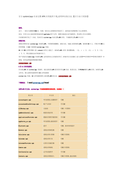
官方system/app目录完整APK应用提供下载,说明和安装方法.【2月11日更新】说明:由于,一部分人刷精简ROM后,发现一部分自己需要的应用没有了,或多或少觉得影响了自己的使用。
而且,许多人自己备份的时候备份的apk+odex两个文件,就算安装进去也不能使用。
其实网上有合并教程。
只好服务伸手党了!在此,发布官方system/app目录完整APK应用。
下面提供完整APK中文名!安装方法:系统自带的目录 system/app 里面的APK。
不需要的就删除。
添加方法,电脑上把需要的APK,复制到SD卡上,手机中用RE文件管理器,从SD卡复制到system/app 里面。
SD卡在RE文件管理器进入sdcard文件夹就是了。
添加的APK 应用需设置权限。
一行;√ √ Ⅹ 二行;√ Ⅹ Ⅹ 三行;√ Ⅹ Ⅹ。
然后重新启动手机就可以了。
用户安装目录data/app 里面的APK,这里是你自己安装的应用了,卸装可以方法最好,进入设置---应用程序--管理应用程序中卸装,因为这样能清理掉缓存数据。
实例说明请到二楼!2月11日补充说明:在安装APK 到 system/app 里面时,请注意检查APK是否存在有LIB目录,检查方法,用WINRAR解压APK应用。
如果有LIB 文件夹,那么请将里面的所有SO文件复制到system/lib 里面,SO文件权限参照上面设置APK的方法。
实例说明请到二楼!下载地址: [ hide]system-app.rar[/hide]自带APK中文名:system/app不是彻底精简列表说明,注意啦!!NEEKH借楼使用!!在此对这位机油表示感谢!删除APK 就不用讲了吧!我这里来实例讲解如何增加官方的APK,已华为输入发为实例讲解!我这里只是举例说明,因为我精简的时候把没有用的SO文件都给DEL了!首先我们在本地检查华为输入的APK 是否包含有LIB文件和SO文件。
鼠标单击HwIME.apk,右键--选择打开方式为WINRAR,如果没有LIB文件夹,没有SO文件的跳过。
华为逆变器TRACKSO安装指南说明书
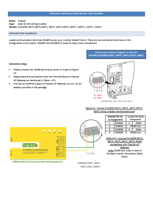
TRACKSO INSTALLATION GUIDE FOR HUAWEIBrand: HuaweiType: Solar On Grid String InverterModels: SUN2000-25KTL,30KTL,33KTL, 36KTL, 40KTL,55KTL, 60KTL, 100KTL, 110KTL, 125KTL CONNECTION DIAGRAMLocate communication terminals (RS485) as per your Inverter Model Picture. There are two connection terminals on the configuration circuit board: RS485IN and RS485OUT (used for Daisy Chain connectionsConnection steps • Please unscrew the RS485 terminal as shown in A part of Figure H1.• Please make the connections from the Terminal Block to TrackSo IoT Gateway as mentioned in Table – HT1.•Provide 12V external supply to TrackSo IoT Gateway via 12V, 2A DC adaptor provided in the packageFigure H1: Huawei SUN2000-33KTL, 36KTL, 40KTL,55KTL,60KTL String Inverter communicatio portTable HT1 – Huawei SUN2000-33KTL, 36KTL, 40KTL,55KTL, 60KTL RS485 connections with TrackSo IoTGatewayNote: RS485 Out- Used in case of Multiple Inverter Connection (Daisychain).Huawei Pin no. & Assignment TrackSo Pin No.&Assignment1 RS485A 3 Data+2 RS485A RS485 Out3 RS485B4 Data- 4 RS485BRS485 OutFollowing Connection Diagram is valid forHUAWEI SUN2000-33KTL, 36KTL, 40KTL,55KTL, 60KTLLocate communication terminals (RS485) as shown in the picture below. There are two connection terminals on the configuration circuit board: RS485IN and RS485OUT (used for Daisy Chain connections)Figure H2: Huawei SUN2000-25KTL,30KTL communicatio port & ConnectionsConnection steps• Please unscrew the RS485 terminal as shown in A part of FigureH2.• Please make the connections from the Terminal Block toTrackSo IoT Gateway as mentioned in Table – HT2.• Provide 12V external supply to TrackSo IoT Gateway via 12V, 2ADC adaptor provided in the package.Table HT2 – Huawei SUN2000-25KTL,30KTL RS485 connections withTrackSo IoT Gateway Note: RS485 Out- Used in case of Multiple Inverter Connection(Daisy chain).Huawei Pin no. & AssignmentTrackSo Pin No.& Assignment5 RS485A 3Data+6 RS485A RS485 Out7 RS485B 4 Data-8 RS485BRS485 OutFollowing Connection Diagram is valid forHUAWEI SUN2000-25KTL,30KTLLocate communication terminals (RS485) as shown in the picture below. There are two connection terminals on the configuration circuit board: RS485IN and RS485OUT (used for Daisy Chain connections)Figure H3: Huawei SUN2000-100KTL,110KTL,125KTL communicatio port & ConnectionsConnection steps• Please unscrew the RS485 terminal as shown in A part of FigureH3.• Please make the connections from the Terminal Block toTrackSo IoT Gateway as mentioned in Table – HT3.• Provide 12V external supply to TrackSo IoT Gateway via 12V, 2ADC adaptor provided in the package.Table HT3 – Huawei SUN2000-100KTL,110KTL, 120KTL RS485connections with TrackSo IoT Gateway Note: RS485 Out- Used in case of Multiple Inverter Connection(Daisy chain).Huawei Pin no. & AssignmentTrackSo Pin No.& Assignment1 RS485A 3Data+2 RS485A RS485 Out3 RS485B4 Data- 4 RS485BRS485 OutFollowing Connection Diagram is valid for HUAWEI SUN2000-100KTL, 110KTL, 125KTLDEFAULT CONFIGURATION IN TRACKSO IOT GATEWAYInverter ID: 1, 2, 3, 4 …. Continuous numbering starting with 1, (Range: 1 to 247)Baud Rate: 9600 (Default) (Values: 9600, 19200, 38400)Data Bits: 8 ,Stop Bit: 1 ,Parity: NoneCONFIGURATION AT THE INVERTER ENDConnect the SUN2000 to the mobile phone that runs SUN2000 app through a Bluetooth module or USB data cable (same as used for commissioning of the inverter)After the successful login, the Quick Settings screen or Function Menu screen is displayedHuawei APP Screenshot SettingsSet Data & TimeFor a precise calculation of the statistics in the inverter itself and in a monitoringsystem, date and time have to be correct.Set Baud RateDefault Value for configuration TrackSo – 9600If you connect multiple inverters via RS485, set the same baud rate on eachinverter.Set ProtocolModbus RTU protocol is to be selected for proper communication setup betweenHuawei and TrackSo IoT GatewaySet communication AddressThe address/ID is used to identify the inverter in a RS485 connection•Set a different inverter ID for each inverter in the PV plant. Otherwise, theinverters cannot be correctly identified.•On the last inverter in the RS485 connection, switch on the RS485 terminationresistorCommunication Card SettingsSingle InverterTerminal Resistor-offMultiple InvertersIf multiple SUN2000s are used, connect all the SUN2000s in daisy chain mode over an RS485 communications cable.When two or more inverters are in parallel communication, the terminal resistor should be switched on or else, it may cause communication interruption.NOTE: The above details are mentioned in the Installation & Operation Manual for SUN2000-(33KTL, 36KTL, 40KTL,55KTL, 60KTL) or Installation & Operation Manual for SUN2000-(25KTL, 30KTL) or Installation & Operation Manual for SUN2000-(100KTL, 110KTL,125KT)。
华为 HUAWEI S-TAG 快速指南

将充电线金属触点对准背面充电口金属触点并平放,另一端连接充电器并接通电源,充电自动开机(指示灯亮起)。
2.充电和开机1.主要清单者您安装的软件不支持而无法实现。
因此,本手册中的描述可能与您购买的产品或其附件并非完全一一对应。
华为保留随时修改本手册中任何信息的权利,无需提前通知且不承担任何责任。
责任限制本手册中的内容均“按照现状”提供,除非适用法律要求,华为对本手册中的所有内容不提供任何明示或暗示的保证,包括但不限于适销性或者适用于某一特定目的的保证。
在适用法律允许的范围内,华为在任何情况下,都不对因使用本手册相关内容及本手册描述的产品而产生的任何特殊的、附带的、间接的、继发性的损害进行赔偿,也不对任何利润、数据、商誉或预期节约的损失进行赔偿。
在相关法律允许的范围内,在任何情况下,华为对您因为使用本手册描述的产品而遭受的损失的最大责任(除在涉及人身伤害的情况中根据适用的法律规定的损害赔偿外)以您购买本产品所支付的价款为限。
数据安全使用非授权第三方软件升级设备的固件和系统,可能存在设备无法使用或者泄漏您个人信息等安全风险。
建议您使用在线升级或者将设备送至您附近的华为授权服务中心升级。
进出口管制若需将本手册描述的产品(包括但不限于产品中的软件及技术数据等)出口、再出口或者进口,您应遵守适用的进出口管制法律法规。
隐私保护为了解我们如何保护您的个人信息,请访问https:///cn/privacy/privacy-policy/阅读我们的隐私政策。
安全信息在使用和操作设备前,请阅读并遵守下面的注意事项,以确保设备性能最佳,并避免出现危险或非法情况。
电子设备有明文规定禁止使用无线设备的场所,请勿使用本设备,否则会干扰其它电子设备或导致其它危险。
对医疗设备的影响·在明文规定禁止使用无线设备的医疗和保健场所,请遵守该场所的规定,并请勿使用本设备。
·设备产生的无线电波或含有磁铁可能会影响植入式医疗设备或个人医用设备的正常工作,如起搏器、植入耳蜗、助听器等。
华为SUN2000 (8KTL-28KTL) 快速安装指南说明书
SUN2000(8KTL-28KTL)快速安装指南文档版本:18部件编码:31505445发布日期:2020-08-20华为技术有限公司1系统安装1.安装设备前请详细阅读《SUN2000 (8KTL-28KTL) 用户手册》,了解产品信息及安全注意事项。
2.必须使用绝缘工具。
单位:mm安装高度应利于LCD 的查看及按钮的操作。
竖直后仰前倾水平倒置确定安装位置1.11.防盗锁为用户自备。
2.挂墙安装请参见《SUN2000 (8KTL-28KTL) 用户手册》。
1.根据背板的尺寸,确定支架上的打孔位置。
2.打孔。
3.固定背板。
M10 (3PCS)30N ·m4.将逆变器安装到背板上。
5.紧固六角螺钉。
6.(可选)安装防盗锁。
安装逆变器(以支架安装为例)1.2单位:mm1.禁止使用单导体硬线。
2.SUN2000-28KTL 为3芯户外线缆(L1、L2、L3),其他机型均为4芯户外线缆(L1、L2、L3、N )。
逆变器型号线缆横截面积(推荐)SUN2000-8KTL/10KTL/12KTL4.0mm 2(12AWG )SUN2000-15KTL/17KTL/20KTL/23KTL/28KTL6.0mm 2(10AWG )/10.0mm 2(8AWG )表中仅给出了推荐的线缆规格,更详细的线缆规格说明请参见《SUN2000 (8KTL-28KTL) 用户手册》。
2电气连接OT-6mm 2-M6PE 端子1.保护地线推荐逆变器近端接地。
2.为了提高PE 端子的防腐性能,建议在保护地线安装完成后,在PE 端子外部涂抹硅胶或刷漆进行防护。
安装保护地线2.1安装交流输出线2.2较大手柄螺丝刀(推荐)N 线插入孔4,L1/L2/L3 不能插入孔。
套筒线缆密封套配合插座咔哒凹口请确保交流输出连接器连接紧牢固可靠,否则设备长时间运行后可能造成连接器损坏。
为快速将交流输出连接器安装到逆变器交流输出端子上,交流输出连接器的凹口应正对操作者。
华为S7712 快速安装指南
20 10(外径6mm)或者20(外 径12mm)
开口波纹管 (推荐)
缠绕管
闭口波纹管
拔纤钳
中心波长
传输速率
传输距离
光模块
15
安装后检查
编号 1 2 3 4 5 6 7 8 9 10 11 12 13 14
15
16 17 18 19 20 21 22 23 24 25
检查项 机柜安装位置符合工程设计文件 机柜结构件规范正确安装,无脱落或碰坏现象 螺钉全部正确紧固 机柜垂直偏差度小于3mm(可利用铅锤进行测量) 主走道侧各行机柜应对齐成直线,误差小于5mm 整行机柜表面应在同一平面,排列紧密整齐 机柜前门打开关闭顺畅 机柜顶部出线口及底部出线口应密封良好 信号电缆走线路由应与工程设计文件相符 信号电缆不应有破损、断裂、中间接头 信号电缆插头干净无损坏,插接正确可靠,芯线卡接牢固 信号电缆布放应理顺不交叉,转弯处留余量。(出机柜1m 内允许交叉) 尾纤在机柜外布放时,不应有其它电缆或物品挤压,且应加套管或槽道保护 光纤进机柜处必须套在波纹管内,波纹管应进入机柜内部,长度不宜超过 100mm,且波纹管应绑扎固定。 光纤的曲率半径应大于光纤直径的20 倍,一般情况下曲率半径大于等于 40mm,光纤的走线路径上,不能有突出元器件。 成对光纤要理顺后用光纤绑扎带绑扎,且绑扎力度适宜。 信号电缆两端标识正确、清晰、整齐。 电源线、地线走线路由符合工程设计文件,便于维护扩容 电源线、地线应采用整段铜芯材料,中间不能有接头,外皮无损伤 电源线、地线连接正确可靠,接触良好 电源线、地线线径符合工程设计文件,满足设备配电要求 电源线、地线与信号线分开布放 电源线、地线走线应平直,绑扎整齐,转弯处留合适余量 电源线、地线、配电开关等标识正确、清晰、整齐 把手是否放置在指定位置
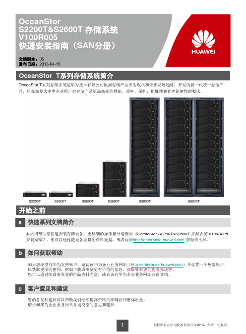
OceanStor S2200T&S2600T 存储系统 V100R005 快速安装指南
维维护护终终端端
应用服务器
外部电源
控制框
硬盘框
3b 连接接地线
外部电源 接地线
8
3c 级联硬盘框
说明 控制框和硬盘框上的EXP级联端口必须与硬盘框上的PRI级联端口连接。 控制器A(控制器B)上的级联端口必须与级联模块A(级联模块B)上的PRI级联端口连接。
控制框
控制器模块A
控制器模块B
硬盘框2 级联模块A
直流电源线连接好的状态 直流配电盒
控制框 硬盘框
13
4 检查硬件安装
4a 检查设备安装
检查项 控制框 硬盘框
正常 平稳地安装在滑道上,无位移。 螺钉已拧紧。
4b 检查线缆连接
检查项
接地线 光纤 mini SAS线 网线 串口线
正常 线缆正确固定并且完全插入。
交流电源线
交流电源线冗余连接至不同的独立电源。 交流电源线卡扣扣好。
场景2 4U设备的安装位置定位
滑道底边位置
固定2U设备螺丝孔的位置 固定可调节滑道螺丝孔的位置
安装浮动螺母位置
滑道底边位置 固定4U设备螺丝孔的位置 固定可调节滑道螺丝孔的位置
5
2d 安装可调节滑道
说明 可调节滑道的可调节长度范围为600mm~900mm,可以安装在深度为800mm~1100mm的机柜中。 发货时可调节滑道已经装配了方孔定位销。如果机柜上的安装螺丝孔为圆孔,请选择圆孔定位销。 安装可调节滑道时务必确保左右两侧的可调节滑道的上顶面在同一水平面上。
开始之前
a 快速系列文档简介
本文档帮助您快速安装存储设备,更详细的操作指导请查阅《OceanStor S2200T&S2600T 存储系统 V100R005 安装指南》。您可以通过随设备发货的资料光盘,或者访问 获得该文档。
华为S系列园区交换机快速配置
开始之前
1
中小园区组网场景
2
数据规划
3
快速配置中小园区
4
大型园区组网场景
16
数据规划
17
快速配置大型园区
19
常见问题
49
更多的参考资料
52
1 开始之前
本文档帮助您首次登录及快速配置华为S系列交换机。更多业务配置,请查阅《交换机配 置指南》。
本文适用于交换机V200R003C00及更高版本。
在开始数据配置之前,请您首先完成如下工作: 1 完成交换机的安装、上电,具体操作请参考《S9700&S7700 快速安装指南》,
[CORE-Eth-Trunk1] port trunk allow-pass vlan 10 //配置Eth-Trunk1透传ACC1上的
业务VLAN
[CORE-Eth-Trunk1] mode lacp
//配置为LACP模式
[CORE-Eth-Trunk1] quit
[CORE] interface GigabitEthernet 0/0/1
Eth-Trunk 类型 静态LACP 配置接口和 VLAN
端口类型
缺省为hybrid
VLAN ID
ACC1:VLAN 10 ACC2:VLAN 20 CORE: VLAN 100
配置路由 IP地址 配置DHCP DHCP Server
CORE: VLANIF100 10.10.100.1/24 VLANIF10 10.10.10.1/24 VLANIF20 10.10.20.1/24
请牢记初次登录时设置的密码,当用户再次通过Console口登录交换机, 需要输入此密码。 完成Console登录密码设置后,用户便可以配置交换机,需要理IP和Telnet
SV22 X6000系列高密服务器操作系统安装
Page 26
常见任务(2/3)
网络配臵界面
Copyright © 2013 Huawei Technologies Co., Ltd. All rights reserved.
Page 27
常见任务(3/3)
Copyright © 2013 Huawei Technologies Co., Ltd. All rights reserved.
Copyright © 2013 Huawei Technologies Co., Ltd. All rights reserved.
Page 30
目录
X6000系列服务器远程管理BMC配臵
X6000系列服务器RAID规划与基本配臵步骤
X6000系列服务器操作系统安装方法
Copyright © 2013 Huawei Technologies Co., Ltd. All rights reserved.
Copyright © 2013 Huawei Technologies Co., Ltd. All rights reserved.
Page 16
2.3.2 系统信息(2/4)
Copyright © 2013 Huawei Technologies Co., Ltd. All rights reserved.
Page 19
远程控制(1/4)
在导航树上选择“远程控制”,进入远程控制界面,远程控
制界面集成了虚拟媒体和KVM OVER IP 功能模块。
当处于全屏模式下时,这些功能菜单会隐藏,可以通过 “Ctrl+Shift+Alt”三键快速显示出来。
华为技术有限公司SUN2000-(25KTL, 30KTL)-US快速安装指南 Issue 02说明
HUAWEI TECHNOLOGIES CO., LTD.SUN2000-(25KTL, 30KTL)-USQuick Installation Guide Issue: 02Part Number: 31507215Date: 2017-11-151Product Overview1.The information in this document is subject to change without notice. Every effort has been made in the preparation of this document to ensure accuracy of the contents, but all statements, information, and recommendations in this document do not constitute a warranty of any kind, express or implied.2.Before installing the device, read the SUN2000-(25KTL, 30KTL)-US User Manual for knowledge of product information and safety precautions.3.Only qualified and trained electrical technicians are allowed to operate the device. Operators should understand the components and functioning of a grid-tied PV power system, and they should be familiar with relevant local standards.4.Before installing the device, check that deliverables are intact and complete against the packing list. If any damage is found or any component is missing, contact the dealer.e insulated tools when installing the device. For personal safety, wear insulation gloves and protective shoes.6.When installing devices or connecting cables, use appropriate tools and take necessary protective measures to avoid damaging devices during operation.7.Huawei shall not be liable for any consequence caused by violation of the storage, transportation, installation, and operation regulations specified in this document and the user manual.Front View(1) PV connection indicator (3) Communications indicator (4) Alarm/Maintenance indicator (6) Maintenance compartment door(5) Host panel(2) Grid-tied indicator Ports(1) DC switch (DC SWITCH)(3) Functional ground point(4) Waterproof cable connector (COM1)(6) Waterproof cable connector (AC OUTPUT)(5) Protective ground point(7) Waterproof cable connector (COM3)(2) Positive DC terminal (+)(8) Waterproof cable connector (COM2)(9) Waterproof cable connector (GND)(10) USB port (USB)(11) Negative DC terminal (–)(12) Ventilation valveNOTICE2System InstallationDetermining the Installation Position2.1It is recommended that the inverter be installed vertically or with a back tilt of no more than 15 degrees for optimal heat dissipation conditions.Installation dimensionsChassis dimensionsDetermining the Installation Mode2.2Installed on a Common SupportVerticalBack tiltUpside downFront tiltHorizontalInstalled on a WallVerticalBack tiltUpside downFront tiltHorizontalNOTEInstalling an Inverter2.3Installed on a Tilted SupportInstalled on a Common SupportBack tiltUpside downFront tiltHorizontal1.Determine the hole positions on the support based on rear panel dimensions.2.Drill holes.4.Mount the inverter on the rear panel.3.Secure the rear panel.M12 (3 PCS)45 N·m6.(Optional) Install an anti-theft lock.5.Tighten hexagon bolts.NOTEThe anti-theft lock is prepared by the customer.Installed on a Wall1.Determine the positions for drilling holes on the wall according to the rear panel dimensions.2.Drill holes and install expansion sleeves for expansion bolts.M12 (3 PCS)45 N·m3.Secure the rear panel.4.Mount the inverter on the rear panel.6.(Optional) Install an anti-theft lock.5.Tighten hexagon bolts.The anti-theft lock is prepared by the customer.Installed on a Tilted Support1.Prepare a tilted support.Front view1.The hole dimensions of the bottom auxiliary tightening point in the top view are OB-13 mm x 8mm (OB-0.51 in. x 0.31 in.).2.The hole dimensions of the tightening point for the tilted support mounting kit in the front view are OB-32 mm x 12 mm (OB-1.26 in. x 0.47 in.).3.The auxiliary tightening point is 5 mm (0.20 in.) away from the lower tightening point for the tilted support mounting kit.NOTENOTETop viewSide view3.Secure the inverter to the tilted support.5.(Optional) Install an anti-theft lock.2.Secure the tilted support mounting kit to the inverter.M6 (8 PCS)4 N·mM6(2 PCS)4 N·mM8(4 PCS)8 N·m4.(Optional) Secure the auxiliary screws to the inverter.The anti-theft lockis prepared by the customer.3Electrical ConnectionInstalling Ground Cables3.1The hex key is stored in the fitting bag bound to the chassis base.1.Remove the two screws from themaintenance compartment door using a hex key and set them aside.Electrical connections must meet local installation regulatory requirements.1.Do not leave unused screws in the chassis.2.Do not open the host panel of the inverter.3.Before opening the maintenancecompartment door, turn off the downstream AC output circuit breaker and DC switch on the inverter.NOTENOTENOTICEWARNING2.Open the maintenance compartment door and adjust the support bar.3.Remove the AC terminal cover and set it aside.Ground Point Meaning Ground PointScrew ModelConnection1PV side ground points M4Connect either of the two groundpoints for PV side grounding.2M63Protection ground points M6Connect either of the two ground points for protective grounding.44.Install ground cables.Installing Ground Cables (Ground Points 1 and 4 Are Used as an Example)NOTE1.Select ground points for PV side grounding and protective grounding based on the principle of easy operation.2.It is recommended that 8 AWG outdoor copper-core cables be used as ground cables. Ground cables must be securely connected.3.It is recommended that ground cables of the inverter be connected to the near end.4.To prevent corrosion, apply silica gel or paint to the PE terminal after connecting the ground cables.Ground Point OT TerminalTightening Torque1M4 1.2 N·m 4M65 N·m1.Route the PV module ground cable through theGND hole at the inverter bottom.2.Route the protective ground cable through the AC OUTPUT hole at the inverter bottom.1.The SUN2000-25KTL/30KTL-US (SUN2000 for short) supports three-phase, four-wire (L1, L2, L3, and N) and three-phase, three-wire (L1, L2, and L3) output modes. Use a connection mode according to the local and national regulations and installation specifications.e copper cables that can withstand 90°C (194°F) or 105°C (221°F).3.It is recommended that the AC output cable be routed through a pipe for protection.4.The table lists only the recommended cable specifications. For more information about cable specifications, see the SUN2000-(25KTL, 30KTL)-US User Manual.Cable Type Cable QuantityRecommended Cable SpecificationsA single cableFour (L1, L2, L3, and N) or three(L1, L2, and L3)4 AWGInstalling AC Output Power Cables3.2NOTE1.The OT terminal type is M6.2.If heat shrink tubing is used, put it through the power cable and then crimp the OT terminal.1.Remove the waterproof cable connector from AC OUTPUT.2.Route the AC output power cable through the prepared cable routing pipe.3.Route the AC output power cable and the cable routing pipe through the AC OUTPUT hole at the inverter bottom.4.Prepare AC output power cables. Use hydraulic pliers to crimp the conductor part of the OT terminal and cover the crimping area with heat shrink tubing or PVC insulation tape.NOTENOTE1.The AC output power cable must be secured to a torque that does not exceed 6 N·m.Otherwise, the AC terminal block may be damaged.2.Ensure that the AC output power cable is securely connected. Otherwise, the inverter may fail to run or the terminal block may be damaged after the inverter operates.6.Secure the cable routing pipe.5.Connect the SUN2000 AC output power cables to the AC terminal block one by one.Three-phase, four-wire outputThree-phase, three-wire outputAdjust the sequence of installing AC output power cables based on site requirements.Positive and negative metal terminalsNegative metal terminal (male)Positive metal terminal (female)Number of Inputs SUN2000-25KTL/30KTL-US 1Connects to any one route 2Connects to routes 1 and 33Connects to routes 1, 3, and 54Connects to routes 1, 2, 3, and 55Connects to routes 1, 2, 3, 4, and 56Connects to routes 1, 2, 3, 4, 5, and 6Optional DC input terminalsRoutes 1, 2, 3, 4, 5, and 6 are defined from left to right.Installing DC Input Power Cables3.3M6 (3 PCS)5 N·mM6 (4 PCS)5 N·m NOTENOTICENOTE1.Before connecting DC input power cables, mark the polarities on the cables to ensure that the cables are connected correctly. If the cables are connected incorrectly, the device may be damaged.2.Insert the crimped metal terminals of the positive and negative power cables into the appropriate positive and negative connectors. Then pull back the DC input power cables to ensure that they are connected securely.3.Connect the positive and negative connectors to the appropriate positive and negative DC input terminals. Then pull DC input power cables to ensure that they are connected securely.4.If the DC input power cables are reversely connected and the DC switch is ON, do not turn off the DC switch immediately. Otherwise, the inverter may be damaged. Wait until the PV string voltage reduces to the safety range. Then, turn off the DC switch, remove the positive and negative connectors, and rectify the connection.5.The damage caused by reverse connection of the DC input power cable is beyond the warranty scope.•Ensure that the PV module output is well insulated to ground.Before inserting the positive and negative connectors respectively into the positive andnegative DC input terminals of the inverter, check that the DC voltage does not exceed 1000 V using a multimeter. Otherwise, the inverter will be damaged.WARNINGNOTICEPositive metal terminalNegative metal terminal Common PV cables with a cross-sectional area of 12 AWG are recommended.Recommended: H4TC0001 (Amphenol)Ensure that cables cannot be removed aftercrimped.Ensure that the locking nut is secured.Recommende d: H4TW0001 (Amphenol)Positive connectorNegative connectorClickEnsure that the cables are correctly connected and the voltage does not exceed 1000 V.Selecting a Communication Mode3.4ModelCommunication ModeRemarksRS485 CommunicationPLCCommunicationSUN2000-25KTL/30KTL-US (with PLC)Supported Supported1.Only one communications mode can be selected in practice.2.If PLC is used, do not connect the RS485 communications cable.3.If RS485 is used, do not connect the PLC CCO module to the AC power cable. SUN2000-25KTL/30KTL-US (without PLC)Supported Not supportedN/AWhen routing communications cables, ensure that communications cables are separated from power cables and away from interfering source to prevent communication from being affected.Installing RS485 Communications Cables3.5NOTE1.If RS485 is used, connect the RS485 communications cable. If PLC is used, do not connect the communications cable.2.The RS485 communications cable can connect to either a terminal block or an RJ45 network port. Use one connection mode in practice. Connecting to the terminal block is recommended.3.If the RS485 communications cable is required, you are advised to route the RS485communications cable through a pipe. Before connecting cables, remove the corresponding waterproof cable connectors.NOTICEMethod 1: Connecting to the Terminal Block (Recommended)The DJYP2VP2-22 2 x 2 x 1 cable or a communications cable with a wire sectional area of 1 mm 2(0.00155 in.2) and external diameter of 14–18 mm (0.55–0.71 in.) is recommended.1.Peel off the RS485 communications cables.2.Connect the RS485 communications cables.3.Bind the RS485 communications cables.1.Route the communications cables through the COM1and COM2holes at the bottom of the inverter.2.Connect the input end to terminals 5 and 7 on the terminal block, and connect the output end to terminals 6 and 8 on the terminal block. Connect the shield layer to the ground point.3.The OT terminal used for connecting to the shield layer is in the type of M4.4.If multiple inverters are connected over communications cables, ensure that RS485A and RS485B of the previous inverter connect to RS485A and RS485B of the following inverter, respectively.4.Secure the cable routing pipe.NOTICE1.Prepare an RS485 connector.The figure shows the connector when the surface without the fastener faces upwards. The following table lists the cable No., color, and pin definition.You are advised to use a CAT 5E outdoor shielded network cable with a diameter less than 9 mm (0.35 in.) and internal resistance no greater than 1.5 ohms/10 m (1.5 ohms/393.70 in.).Method 2: Connecting to RJ45 PortsNo.Color Pin Definition 1White-and-orangeRS485A, RS485differential signal +2Orange RS485B, RS485 differential signal –3White-and-greenNC4Blue RS485A, RS485 differential signal +5White-and-blueRS485B, RS485 differential signal –6Green NC 7White-and-brownNC 8BrownNC2.Connect the RS485 communications cables.3.Bind the RS485 communications cables.4.Secure the cable routing pipe.NOTICE1.Route the network cables into the COM1hole at the bottom of the inverter.2.Insert the connectors into the RS485 IN and RS485 OUT ports in the maintenance compartmentof the inverter.3.Block unused waterproof cable connectors with waterproof plugs.4Installation Verification1.The SUN2000 is installed correctly and securely.Yes □No □2.All circuit breakers are switched to OFF.Yes □No □3.Cables connected are not damaged.Yes □No □4.Ground cables are connected correctly and securely, with no open circuit orYes □No □short-circuit.5.AC output power cables are connected correctly and securely, with no openYes □No □circuit or short-circuit.6.The DC input voltage is not higher than 1000 V and meets the local voltageYes □No □range requirements.7.DC input power cables are connected correctly and securely, with no open circuitYes □No □or short-circuit.8.RS485 communications cables are connected correctly and securely.Yes □No □9.Idle DC input terminals are sealed.Yes □No □10.Idle USB ports are plugged with covers.Yes □No □11.Idle waterproof cable connectors are plugged and the locking caps are tightened.Yes □No □NOTICEAfter the verification, reinstall the AC terminal cover, adjust the support bar, and close the maintenance compartment door. Then, tighten the two screws on the door to a torque of 4 N·m. Check that the maintenance compartment door is locked.5System Power-on1.Switch on the AC circuit breaker between the inverter and the power grid.2.Press DC SWITCH at the bottom of the inverter and rotate it to the ON position.3.(Optional) Measure the temperatures at the joints between the DC terminals and theconnectors using a thermometer.4.Observe the LED indicators to check the inverter operating status.Indicator Status MeaningPV connection indicator Steady greenAt least one PV string is properly connected, andthe DC input voltage of the corresponding MPPTcircuit is higher than or equal to 200 V.OffThe inverter disconnects from all PV strings, orthe DC input voltage of each MPPT circuit is lessthan 200 V.Grid-tie indicator Steady greenThe inverter is grid-tied. Off The inverter is not grid-tied.Communication indicator Blinking green (on for 0.5s andoff for 0.5s)The inverter receives data over RS485/PLCcommunication.OffThe inverter has not received data overRS485/PLC communication for 10 seconds.Alarm/ Maintenance indicator Alarm stateBlinking redslowly (on for 1sand then off for4s)The inverter has generated a warning.Blinking red fast(on for 0.5s andthen off for 0.5s)The inverter has generated a minor alarm.Steady red The inverter has generated a major alarm.LocalmaintenancestateBlinking greenslowly (on for 1sand then off for1s)Local maintenance is in progress.Blinking greenfast (on for0.125s and offfor 0.125s)Local maintenance has failed.Steady green Local maintenance is successful.Before switching on the AC circuit breaker between the inverter and the power grid, use a multimeter to check that the AC voltage is within the specified range.NOTICENOTICEIf the DC input power cables are reversely connected and the DC switch is ON, do not turn off the DC switch immediately. Otherwise, the inverter may be damaged. Wait until the PV string voltage reduces to the safety range. Then, turn off the DC switch, remove the positive and negative connectors, and rectify the connection.6SUN2000 APP1.The SUN2000 application is a mobile app that enables the SUN2000 to communicate with the SUN2000 monitoring system to query alarms, configure parameters, and perform routine maintenance. The mobile app is a convenient platform for monitoring and maintenance. The mobile application name is SUN2000.2.At present, the SUN2000 can connect to the app only over a USB data cable.3.Mobile operating system: Android4.0 or later.4.Access the Huawei app store () or Google Play(https://), search for SUN2000, and download the SUN2000 APP software package.5.The SUN2000 communicates with its mobile application through a USB cable connected over the USB port.6.This document uses the WebUIs of SUN2000APP V200R001C00 as an example.Data Cable ConnectionInverterUSB data cableMobile phoneNOTELogin screenSwitch between usersConnect the USBdata cableSelect USB connection1.Tap to return to the login screen.2.Inverter grid connection setup requires no parameter setting by default. The parameters can be adjusted based on site requirements. For parameter settings, see the SUN2000 APP User Manua l.1.The password is the password used for logging in to the SUN2000 to which the app is connected. This password is used only when the SUN2000 is connected to the app.2.The initial password for Common User , Advanced User , and Special User is00000a . Use the initial password to log in to the inverter for the first time and change the password immediately to ensure account security.3.During the login, if an incorrect password is entered for five consecutive times (the interval between two consecutive invalid password entries is less than 2 minutes), the account will be locked for 10 minutes.Function menuQuick settings NOTENOTICE7FAQThe DC switch is designed with a hole for safety purposes. When maintenance needs to beperformed on the inverter, the DC switch must be turned off. To prevent misoperations of turning on the DC switch, the switch must be locked. The design with a hole enables the DC switch to be locked.After the inverter has been running for a period, use a point-test thermometer to measure the temperatures at the joints between DC terminals and connectors to check that the DC terminals are in good contact.Why the DC Switch Is Designed with a Hole?7.1What Is the Purpose of Measuring the Temperatures at the Joints Between DC terminals and Connectors Using a Point-Test Thermometer?7.2Appendix: Power Grid Code Mapping TableThe grid codes are subject to change and are for your reference only.No.Power Grid Standard Code Country and Condition 1IEEE 1547-MV480US medium-voltage power grid 2IEEE 1547a-MV4802016 US medium-voltage power grid 3PRC_024_ERCOT-MV480Texas medium-voltage power grid 4PRC_024_Eastern-MV480Eastern US medium-voltage power grid 5PRC_024_Western-MV480Western US medium-voltage power grid 6PRC_024_Quebec-MV480Quebec medium-voltage power grid 7ELEC RULE NO.21-MV480California medium-voltage power grid 8HECO-MV480Hawaii medium-voltage power gridNOTEScan here for more documents:You can also log in to Huawei technical support website:SupportScan here for technical support (carrier):Huawei App StoreHuawei Technologies Co., Ltd.Huawei Industrial Base, Bantian, Longgang Shenzhen 518129 People's Republic of ChinaWeChatGoogle PlayApple Store。
华为桌面云软件安装操作手册
一、安装Linux OS的基础架构组件 ...................................................................................................................................................创建Linux OS基础架构虚拟机 ...................................................................................................................................................安装GaussDB/HDC/WI/License组件 ..........................................................................................................................................安装vAG/vLB组件.......................................................................................................................................................................二、安装Windows OS的基础架构组件 ............................................................................................................................................ AD/DNS/DHCP部署场景介绍..............................................................................................................................................................制作基础架构虚拟机模板...................................................................................................................................................................创建并设置基础架构虚拟机...............................................................................................................................................................新建AD/DNS/DHCP组件........................................................................................................................................................... 错误!安装AD/DNS服务.............................................................................................................................................................. 错误!安装DHCP服务.................................................................................................................................................................. 错误!创建域帐号......................................................................................................................................................................... 错误!配置备份和安全................................................................................................................................................................. 错误!配置DNS策略.................................................................................................................................................................... 错误!配置局方AD/DNS/DHCP组件................................................................................................................................................... 错误!安装ITA组件 ............................................................................................................................................................................. 错误!安装Loggetter/TCM组件 .......................................................................................................................................................... 错误!安装Loggetter组件 ................................................................................................................................................................... 错误!安装TCM组件 ........................................................................................................................................................................... 错误!初始配置..................................................................................................................................................................................... 错误!配置虚拟化环境......................................................................................................................................................................... 错误!配置域......................................................................................................................................................................................... 错误!配置桌面组件............................................................................................................................................................................. 错误!配置告警组件............................................................................................................................................................................. 错误!配置时间同步............................................................................................................................................................................. 错误!检查组件状态............................................................................................................................................................................. 错误!激活Windows基础架构虚拟机的操作系统............................................................................................................................ 错误!(可选)配置桌面云地址......................................................................................................................................................... 错误!操作场景............................................................................................................................................................................. 错误!一、安装Linux OS的基础架构组件••••创建Linux OS基础架构虚拟机•••操作场景该任务指导软件安装工程师创建Linux OS基础架构虚拟机。
HUAWEI华为 MateStation S 12代酷睿版 用户指南 使用说明书

用户指南目 录了解计算机外观介绍1键盘2开启和关闭计算机3F10 一键恢复出厂3获取精彩功能3安全信息个人信息和数据安全法律声明了解计算机外观介绍21电源键•关机状态下,短按电源键,可开启计算机。
•开机状态下,长按电源键 10 秒以上,可强制关闭计算机。
2耳麦接口连接耳机。
3USB-A (USB 3.2 Gen 1) 接口 x 2连接手机、U 盘等外接设备传输数据。
4麦克风输入接口连接麦克风,可将麦克风接收到的声音输入计算机。
5音频输出接口连接音箱等外部设备,将计算机内的音频信号传送至外部设备。
6音频输入接口连接外部音频设备,将外部设备声音传送至计算机。
7HDMI 接口高清晰度多媒体接口,连接显示设备。
8USB-A (USB 2.0) 接口连接手机、U 盘等外接设备传输数据。
9USB-A (USB 3.2 Gen 1) 接口 x 2连接手机、U 盘等外接设备传输数据。
键盘计算机配置的键盘不同,支持功能也会不同,请以实际为准。
快捷键功能介绍部分型号键盘的 F1、F2 等键默认为快捷键(热键)模式,可用于轻松执行常见任务。
快捷键与功能键切换在功能键模式下,运行不同的软件时,F1、F2 等键被定义不同的功能。
若要将 F1、F2 等键作为功能键使用,您可以:按下 Fn 键,当 Fn 键指示灯亮起,表示已将 F1、F2 等键锁定为功能键模式。
只需再次按 Fn 键,开启和关闭计算机将计算机各部分组装完成后,短按计算机主机的电源键,电源键的指示灯亮起,表示主机开启。
计算机正常使用时,单击 > ,使计算机进入睡眠、关机或重启等状态。
强制关机:长按电源键 10 秒以上,可强制关机。
强制关机会导致未保存的数据丢失,请谨慎使用。
F10 一键恢复出厂计算机内置的 F10 系统恢复出厂功能,能短时间内帮您将计算机系统恢复到初始状态。
系统恢复出厂会删除 C 盘中数据(也包含桌面文件、下载、文档等个人数据),请您备份 C 盘内的个人数据。
华为S3526交换机-配置指导-S3526安装手册
Copyright© 2002 by Huawei Technologies Co., Ltd.
All Rights Reserved.
No part of this document may be reproduced or transmitted in any form or by any means without prior written consent of Huawei Technologies Co., Ltd.
z 第五章 启动与配置 介绍 Quidway® S3526 交换机的启动过程与配置基 本知识 包括 交换机的上电启动 系统初始化 配置模式及配置中可 以获得的帮助等内容
z 第六章 软件升级 介绍 Quidway® S3526 交换机的多种软件升级方法
z 第七章 故障处理 介绍 Quidway® S3526 交换机安装启动过程中可能出 现的问题及检查方法
非经本公司书面许可 任何单位和个人不得擅自摘抄 复制本书内容 的部分或全部 并不得以任何形式传播
® HUAWEI® 华为® C&C08® EAST8000® HONET® 视点® ViewPoint® INtess® ETS® 万维通快车站® DMC® SBS® TELLIN®
InfoLink® Netkey® Quidway® SYNLOCK® Radium® 雷霆®
打9
差
改进结构编排 改进目录结构 增加图形说明 增加典型实例 提供更多帮助信息
请您对以上改进建议进行详细说明
表达应更详细 表达应更简洁 专业性不要太强 改进索引方法 增加 step by step 描述
3. 您对本手册的哪些内容比较满意
4. 其他建议
为了我们能够及时与您联系 请填写有关您本人的以下信息
31504188-OSN 3500 快速安装指南-(01)
27
9 Installing and Routing External Clock Cables 安装布放外时钟电缆
29
10 Installing and Routing the Network Management Cable 安装布放网管电缆
32
11 Installing Extended Subrack Cables 安装扩展子架电缆
Trademarks and Permissions
and other Huawei trademarks are trademarks of Huawei Technologies Co., Ltd. All other trademarks and trade names mentioned in this document are the property of their respective holders.
华为服务器系统安装步骤
RH2285 EP Wi ndows Server 2008安装手册拟制:陈远明KF59885日期:2012-2-24 Prepared by Date审核:日期:Reviewed by Date批准:日期:Gran ted by DateHUAWEI华为技术有限公司Huawei Technologies Co., Ltd.版权所有侵权必究All rights reserved1安装前准备1.1 硬件环境准备1、操作系统安装光盘:Win dows2008 R1 sp2 32 位系统需两张光盘:一张系统盘,一张升级成sp2光盘Win dows Server 2008 R2 sp1 64 位系统需一张系统光盘2、USB光驱一个3、USB软驱一个1.2 软件环境准备1. LSI硬盘控制器驱动如果是LSI 2308硬盘驱动器,则需加载2308驱动,驱动如下所示:2308_wi n2k8_x86_2.0.49.0.zip (解压后并拷贝到软盘中)注:也可以使用虚拟软驱挂载虚拟镜像文件:2308_wi n2k8_x86_2.0.49.0.img如果是LSI 2208硬盘驱动器,则需加载2208驱动,驱动如下所示:2208_wi n2k8_x86_5.1.112.zip (解压后并拷贝到软盘中)注:也可以使用虚拟软驱挂载虚拟镜像文件:2208_wi n2k8_x86_5.1.112.img2. chipset驱动程序:chipset_923.1017.zip3. In tel 82580网卡驱动32 为系统使用82580_win2k8_x86_11.14.48Q.exe64 位系统使用82580_win2k8r2_x86_64_11.14.48.0.exe1.3 环境配置1、单板在启动阶段点击“DEL ”键,设置BIOS时间为当前时间,如图1-1。
1-12、输入“ F9 ”,将BIOS 的设置进行“ Load Optimal Default ”操作,如图1-2,“YES ”确认。
- 1、下载文档前请自行甄别文档内容的完整性,平台不提供额外的编辑、内容补充、找答案等附加服务。
- 2、"仅部分预览"的文档,不可在线预览部分如存在完整性等问题,可反馈申请退款(可完整预览的文档不适用该条件!)。
- 3、如文档侵犯您的权益,请联系客服反馈,我们会尽快为您处理(人工客服工作时间:9:00-18:30)。
S7703快速安装指南修订记录修订记录累积了每次文档更新的说明。
最新版本的文档包含以前所有文档版本的更新内容。
文档版本01(2010-12-25)第一次正式发布。
文档版本02(2011-1-15)相对于版本01(2010-12-25)的变化如下:修改:交流配电盒接线图,并增加外部电源线和地线的走线说明。
增加:z机框安装完成后的注意事项。
z拔纤钳的使用场景。
z上电前检查是否有环路组网。
z安装单板的章节。
注意事项•本文档用于为设备硬件安装提供简明快捷的操作指导,配电和机柜安装请参阅随设备发货的光盘中的《配电指导》和《机柜安装指南》。
•本文档对于出厂前已完成的安装操作,如内部线缆安装不进行介绍,仅对现场安装涉及的操作进行介绍。
静电在接触设备、单板、IC 芯片等之前,为防止人体静电损坏敏感元器件,必须佩戴防静电手腕,并将防静电手腕的另一端良好接地。
绑扎线缆机柜内部•网线、光纤线或者光纤绑扎带的绑扎间隔不超过250mm。
•电源线、接地线所用线扣的绑扎间隔不超过250mm。
机柜外部•所有线缆和波纹管的线扣绑扎距离以两横梁之间的间距为准。
•没有横梁的走线槽按照不超过250mm的间距绑扎。
粘贴标签/标识牌•标签/标识牌默认粘贴位置在距离连接器20mm 处。
•当电缆垂直布放时标签/标识牌朝向右。
•当电缆水平布放时标签/标识牌朝向下。
•电源线在安装完成之前禁止与供电设备相连接。
•建议电源线和信号线缆分开走线。
•一台设备上不能混合使用直流电和交流电。
•一柜多框的情况下,机框之间距离不得小于1U(1U=44.45mm)。
长卷尺十字螺丝刀一字螺丝刀活动扳手热风枪裁纸刀压线钳断线钳剥线钳冷压钳网线测试仪万用表羊角锤冲击钻记号笔网线钳斜口钳安装准备1安装工具套筒扳手光功率计梯子铅直测定器机柜选择a安装准备2安装环境机柜尺寸高度N66E 600mm×600mm×2200mm(宽×深×高)46U N68E600mm×800mm×2200mm(宽×深×高)46U•使用华为机柜S7703可以安装在19英寸标准机柜中。
•如果使用N66E机柜,建议使用单开门机柜。
•并柜时,机柜必须带侧门,否则影响散热系统工作。
•机柜的具体内容请参见《Quidway S7700 智能路由交换机硬件描述》中的“N66E 机柜简介”和“N68E 机柜简介”。
•机柜的安装操作步骤请参阅随机柜发货的《N66E 机柜安装指南》和《N68E 机柜安装指南》。
对机柜有如下要求:•有足够的安装高度空间(≥5U),机柜深度要600mm以上。
•安装位置要有滑道。
•不推荐中立柱机柜,否则影响走线量。
安装前检查b序号检查项1确认机房提供的配置条件:•直流电压:-48V:-38.4V ~-57.6V(额定电压:-48V)-60V:-48V ~-72V(额定电压:-60V)•交流电压:100V~240V AC,50/60Hz(额定电压:110V/220V)配电柜至少有2个空余端口(空开小于40A,大于20A)。
确认ODF已安装完毕,并且有足够的空余端口。
确认机房接地排已安装完毕。
检查浮动螺母(若干)是否齐全。
检查机柜是否有滑道和浮动螺母。
2345序号检查项6检查用于迅速定位机箱在机柜中的安装位置的安装模板是否存在。
•不使用华为机柜1机箱安装准备安装分线齿a安装机箱将定位销钉套上葫芦孔,固定一个螺钉。
安装方法:调节挂耳位置b为了适应不同的机柜要求,S7703可以调整挂耳安装的前后位置。
•默认安装位置方孔条到前门距离为95mm ,B=585mm ,A=88mm•需要把挂耳反过来安装方孔条到前门距离为193mm ,B=585mm ,A=186mm•机柜深度大于等于800mm B=585mm ,A=108mm 或者68mm葫芦孔侧面图侧面图侧面图2定位S7703在机柜中的安装位置安装机箱两人合作,对齐孔位,固定安装模板。
裁剪安装模板a固定安装模板b用记号笔标记位置C安装浮动螺母和滑道d用记号笔标记所有浮动螺母和滑道位置。
1、安装浮动螺母2、安装滑道(,)安装机箱到机柜安装机箱搬运机箱入机柜a固定机箱b安装机箱到机柜3安装机箱到机柜安装后注意事项c1、请将随设备发货的拔纤钳固定放置在机柜或机架中,后续操作高密度网口板上的网线、光纤时能方便取用到。
2、请勿将设备的出风口堵上,否则会影响设备的正常散热。
1安装前准备安装单板2安装MCU板3安装LPU板S7703有3个LPU 板槽位,编号为1~3。
S7700机框安装LPU 板的方法是一样的,这里的图形以S7712的机框来举例说明。
1、S7703机框的槽位信息请参见《Quidway S7700 智能路由交换机硬件描述》中的“设备结构”中的槽位分布示意图。
2、安装单板前需要将待安装槽位的假面板拆卸下来。
3、请佩戴防静电手腕或防静电手套进行安装单板的操作,禁止裸手操作。
4、在安装单板过程中,务必缓慢、平稳地沿着机框插槽的导轨插入,避免上下晃动而导致碰到单板上的元器件,以免损坏单板。
5、在安装单板过程中,严禁用手接触单板上的元器件,以免损坏单板。
S7703的MCU 板插在4和5号槽位。
1线缆准备安装保护地线设备接地线2机柜接地机柜接地线另一端接到机房的接地排上。
3设备接地机箱接地线固定在滑道的机柜内侧的接地点上。
机柜接地线设备接地点机柜接地点(,)安装电源线如果使用华为公司机柜,配电盒和内部电源线布线已经完成,只需连接:•配电盒到直流电源模块的直流电源线。
•配电盒到用户配电盒外部直流电源线。
场景适用场合直流电源模块接线端子类型直流配电盒外接端子类型线缆截面积16 mm^225 mm^235 mm^26 mm^216 mm^2≤14.8m ≤23.1m OT端子≤60m-用户配电屏到直流电源模块的距离一个机柜中多个设备-≤160m用户配电屏空余电源输出路数充足用户配电屏到机柜上直流配电盒的距离使用配电盒场景OT端子≤32.4m不使用配电盒场景OT端子-1布放直流电源线不使用配电盒场景a•只体现直流电源模块的安装,参见使用配电盒场景。
•走线方法同样参见使用配电盒场景。
安装电源线1布放直流电源线使用配电盒场景b蓝色(NEG )电缆黑色(RTN )电缆黄绿双色接地电缆输出区输入区(,)安装电源线场景适用场合交流电源模块接线端子类型交流配电盒外接端子类型用户配电屏到交流电源模块的距离一个机柜中多个设备冷压端子-用户配电屏空余电源输出路数充足-≤30m 用户配电屏到机柜上交流配电盒的距离使用配电盒场景交流插头≤25m不使用配电盒场景交流插头-使用配电盒场景a2布放交流电源线不使用配电盒场景b•只体现交流电源模块的安装,走线方法同样参见使用配电盒场景。
输入区输出区配电盒输出端子接线方法外部电源线和地线走线说明:1、在交流配电盒的后面走线,从上面走到下面2、在交流配电盒的底部走线,从后面走到前面3、在交流配电盒的前面走线,从下面穿到接线端子上黑色(L )电缆蓝色(N )电缆黄绿双色(PE )电缆1接口接口编号规则S7703采用“槽位号/子卡号/接口序号”的编号规则来定义接口。
子卡为0或者1。
2布放网线在线缆比较多的情况下:1、单板侧建议三层布放2、可以采用拔纤钳辅助操作,压住簧片即可3布放光纤保护管类型最大可容纳光纤数开口波纹管60闭口波纹管20缠绕管10(外径6mm)或者20(外径12mm)•光纤套在波纹管内,波纹管两端的管口必须用胶带缠好。
•进行光纤的安装、维护等各种操作时,严禁肉眼靠近或直视光纤出口。
•光纤的曲率半径应大于光纤直径的20倍,一般情况下曲率半径≥40mm。
开口波纹管(推荐)缠绕管闭口波纹管距离机柜100mm处可使用如下类型的保护管传输速率中心波长传输距离光模块拔纤钳安装后检查编号检查项检查方法1机柜安装位置符合工程设计文件查看安装位置2机柜结构件规范正确安装,无脱落或碰坏现象查看3螺钉全部正确紧固查看4机柜垂直偏差度小于3mm(可利用铅锤进行测量)测量5主走道侧各行机柜应对齐成直线,误差小于5mm测量6整行机柜表面应在同一平面,排列紧密整齐查看7机柜前门打开关闭顺畅查看8机柜顶部出线口及底部出线口应密封良好查看9信号电缆走线路由应与工程设计文件相符查看10信号电缆不应有破损、断裂、中间接头查看11信号电缆插头干净无损坏,插接正确可靠,芯线卡接牢固查看12信号电缆布放应理顺不交叉,转弯处留余量。
(出机柜1m 内允许交叉)查看13尾纤在机柜外布放时,不应有其它电缆或物品挤压,且应加套管或槽道保护查看14光纤进机柜处必须套在波纹管内,波纹管应进入机柜内部,长度不宜超过查看测量100mm,且波纹管应绑扎固定。
查看测量15光纤的曲率半径应大于光纤直径的20 倍,一般情况下曲率半径大于等于40mm,光纤的走线路径上,不能有突出元器件。
16成对光纤要理顺后用光纤绑扎带绑扎,且绑扎力度适宜。
查看17信号电缆两端标识正确、清晰、整齐。
查看18电源线、地线走线路由符合工程设计文件,便于维护扩容查看19电源线、地线应采用整段铜芯材料,中间不能有接头,外皮无损伤查看20电源线、地线连接正确可靠,接触良好查看21电源线、地线线径符合工程设计文件,满足设备配电要求查看22电源线、地线与信号线分开布放查看23电源线、地线走线应平直,绑扎整齐,转弯处留合适余量查看24电源线、地线、配电开关等标识正确、清晰、整齐查看1上电前检查电源线及接地编号检查项检查方法1所有电源线、地线采用整段铜芯线缆,中间不能查看安装位置有接头并按规范要求进行可靠连接。
查看2设备的电源线、地线连接可靠。
接地端子的弹垫是否在平垫上面。
3制作电源线和地线的线鼻时要焊接或压接牢固。
查看查看4机柜外电源线、地线走线平直,与其他电缆分开绑扎5地线、电源线的余长要剪除,不能盘绕测量6机柜门板的连接地线要求连接紧固可靠查看信号电缆检查表编号检查项检查方法1全部信号电缆在布放前通过导通测试查看安装位置2信号线缆不能布放于机柜的散热网孔上查看3电缆在转弯处按要求留出余量,不得拉紧查看测量4走线平直、顺滑,机柜内电缆无交叉,机柜外电缆绑扎成束查看5各信号线两端标志清晰(贴标签),标签朝向一致。
6有固定螺钉的电缆,必须把螺钉拧紧查看设备组网检查表编号检查项检查方法查看组网图1为避免环路对现网的影响,请确保新增设备不会导致网络出现环路,比如:通过两条链路和同一台现网设备连接。
2设备上电指示灯颜色含义绿色常亮:表明在位单板上电,软件未运行。
快闪(4Hz ):表明系统正在启动。
慢闪(0.5Hz ):表明系统处于正常运行状态。
红色常亮:表明单板故障。
橙色红灯、绿灯同时点亮时显示为橙色,表明单板插入机框,单板上电。
