DC-868智能电容器使用说明书
电子电容计使用方法说明书

电子电容计使用方法说明书1. 介绍电子电容计是一种用于测量电路中电容值的仪器。
本说明书将详细介绍电子电容计的使用方法,帮助用户正确操作并获取准确的测量结果。
2. 产品特点- 高精度:本电子电容计具有高精度的测量功能,能够测量电路中的微弱电容值。
- 显示屏幕:配备LCD显示屏幕,清晰明了地显示测量结果。
- 自动识别:自动识别被测电容的单位,方便用户操作。
- 多功能:除了测量电容值,该电子电容计还具备其他功能,如测量温度和电压等。
3. 基本操作流程为了确保准确测量电路中的电容值,按照以下操作流程进行操作:步骤一:准备工作- 将电子电容计连接到待测电路的电容器两端。
- 打开电子电容计电源,待仪器启动完成后,进入待机状态。
步骤二:选择测量模式- 根据被测电容器的特点,选择合适的测量模式。
常见的模式包括电介质测量模式和串联模式等。
步骤三:调整测量参数- 根据需要,调整电子电容计的测量参数,如频率、电压范围等。
确保参数设置与被测电容器相匹配。
步骤四:执行测量- 确认参数设置无误后,执行测量操作。
电子电容计将会对电容器进行测量,并在显示屏上显示测量结果。
步骤五:记录结果- 确认测量结果无误后,记录电容器的电容值。
可以通过截屏、拍照或手动记录的方式保存结果。
4. 注意事项- 在测量过程中,尽量保持电子电容计与其他电源分离,以避免干扰对测量结果的影响。
- 在测量前,确保电路已断开电源,并将电容器的电荷放电,以避免安全问题。
- 在调整测量参数时,要根据被测电容器的特点和要求,选择合适的参数设置。
- 电子电容计的仪器使用时应避免受到强磁场和强电磁辐射等干扰,以确保测量准确性。
5. 故障排除在使用电子电容计时,可能遇到以下故障情况,可根据情况进行排除:- 无法启动:检查电源是否连接正常,电池是否有电。
- 显示异常:检查显示屏是否清晰、无损坏,是否需要更换。
- 测量不准确:检查测量参数设置是否正确,被测电容器是否有损坏或有其他干扰。
DC868智能低压电容器说明书

DC868系列常规型智能低压电容器产品使用说明安装和使用前认真阅读并理解本册内容检查产品附件按要求安装、调试目录一、安全使用注意事项 (3)二、产品概述 (3)三、产品主要技术参数 (3)四、产品型号说明 (4)五、产品常规型号规格表 (4)六、产品外形及安装尺寸 (5)七、智能电容安装说明 (5)1、拆除外包装 (5)2、智能电容概观 (6)3、安装要求 (6)4、产品安装示意 (7)七、现场检查 (8)1. 接线正确性检查注意事项: (8)2. 产品工作正常性检查注意事项: (8)3. 上电前注意事项: (8)八、人机显示与操作说明 (8)1. 功能描述 (8)2. 界面描述 (8)3、显示与操作 (10)4. 菜单示例 (12)九、产品常见错误与异常处理 (16)1.常见错误 (17)2.常见异常处理 (17)一、安全使用注意事项在安装、保养和使用我公司低压智能电力电容器时,请仔细阅读这些说明内容并谨慎操作,以便能够充分利用电容器的功能,延长本机的使用寿命。
对因使用不当造成的损失,本公司不承担责任。
1、请勿撞击!2、电源线的规格应满足用电负荷的要求,30kvar 及以上容量的电容器使用16 mm2截面积的多芯铜导线。
请正确连接A、B、C 相,外壳应可靠接地。
3、在保养电容器之前,请把电容器开关全部退掉。
4、电容器正常运行期间,如果外壳没有可靠接地,电容器本体可能带电,请勿触摸电容器金属部分,否则有触电可能。
二、产品概述DC868系列智能低压电容器是以二组(△型)或一组(Y型)低压电力电容器为主体,集成了现代测控、电力电子、网络通讯、自动化控制等先进技术,替代传统的由控制器、熔丝、复合开关或机械式接触器、热继电器、低压电容器、指示灯等分离器件在柜内用导线连接而组成的成套无功补偿装置。
由它组成的低压无功补偿装置具有补偿方式灵活、补偿效果好、装置体积小、功耗低、安装维护方便、使用寿命长、保护功能强、可靠性高等特点,并真正做到过零投切,满足用户对设备的实际需求,适应了现代电网对无功补偿设备的更高要求。
KC868 智能家居控制主机 使用说明书
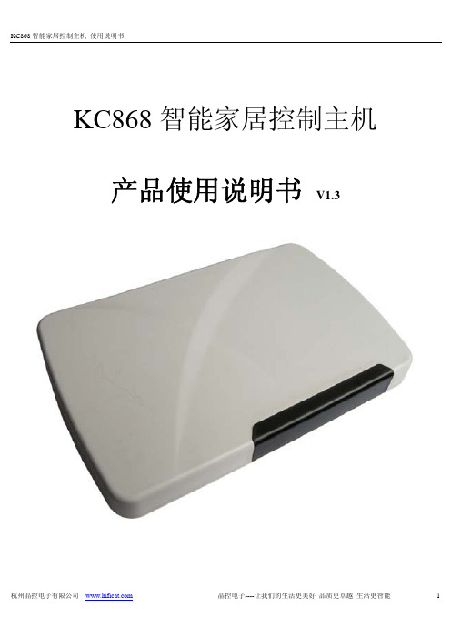
KC868智能家居控制主机产品使用说明书V1.3一、 产品规格参数详细参数主机尺寸:160 x 104 x 30 (mm)外形颜色:白色电压:DC12V功率:1W重量:267g环境:温度:-20℃-+60℃;湿度:10%-95%外置315M、433M天线,标准以太网接口,SIM卡接口内置温度传感器:实时监控主机工作温度,保证主机稳定可靠。
无线参数无线载波频率:ASK:315MHz+/- 150KHz /;433.92MHz +/- 150KHz/ 拥有200路发射通道GSM蜂窝频率:GSM 850/900/1800/1900M红外线码频率:38khz 拥有200路红外线学习/发射通道无线控制无线控制协议:2262、1527,PT2262编码的震荡电阻、地址码、数据码可任意配置无线控制距离:KC868配备了大功率315MHz无线射频发射装置,发射距离理论值空旷地约4000米,实测可以穿透4-5层楼。
无线输入通道:200路无线输入、200路无线输出无线红外控制:标准38KHz红外线编码发射无线温度传感器:可增配8路无线温度传感器结点组合控制8组定时控制:可定时驱动所有输出和更换工作场景,掉电时钟保持。
可自由配置星期规律,实现不同的定时方案。
8组来电控制:来电进行电话号码识别后,控制输出和更换工作场景,可设置8个电话号码作为情景模式触发源,电话号码可任意编辑。
8组短信控制:接收短信内容进行识别后,控制输出和更换工作场景,可设置8个短信内容作为情景模式触发源,短信内容可任意编辑。
200组无线传感器控制:200路无线传感器触发信号,控制输出和更换工作场景,可设置8个电话号码作为情景模式触发源。
20组情景控制:每种场景支持10路输出组合操作。
用户可根据自己的需求配置触发命令:触发命令来源:1、定时2、电话3、短信4、无线输入情景模式控制输出对象:1、无线2、红外3、电话4、短信5、设防6、解防网络控制带加密功能的网络控制功能,支持局域网、宽带网、GPRS、WiFi等网络系统。
电力行业电容表使用方法说明书

电力行业电容表使用方法说明书一、产品概述电容表是电力行业常用的电力仪表之一,用于测量电路中的电容值。
本说明书将详细介绍电容表的使用方法,让用户能够正确、安全地操作电容表。
二、安全注意事项在使用电容表之前,请务必遵守以下安全注意事项:1. 仔细阅读本说明书,了解电容表的使用方法和注意事项。
2. 确保使用环境干燥、通风良好,避免高温、高湿的环境。
3. 在使用电容表之前,确保电流已切断,避免发生电击事故。
4. 使用合适的测试线缆和夹具,确保电容表与被测电路正确连接。
5. 在测量高电压电容时,使用绝缘手套和绝缘工具,以确保人身安全。
三、电容表的基本功能电容表具有以下基本功能:1. 电容测量:能够准确测量电路中的电容值。
2. 自动量程调节:根据被测电容的大小,自动调整测量范围,提高测量精度。
3. 数字显示:采用数字显示屏,直观显示电容值。
4. 数据保存:可以保存测量结果,方便后续查看和分析。
四、电容表的使用步骤以下为电容表的使用步骤:1. 准备工作:a. 确保电容表已经校准并处于正常工作状态。
b. 准备好测试线缆和夹具,并确保其良好的电气连接性能。
c. 根据测量需求,选择合适的电容表测量范围。
2. 连接被测电路:a. 使用测试线缆将电容表与被测电路正确连接。
确保连接牢固并无松动。
b. 根据连接方式,选择正确的夹具进行连接。
3. 打开电容表:按下电容表的开关按钮,启动电容表。
4. 进行测量:a. 根据需要,选择电容表上的测量模式。
b. 将电容表的测试引线分别连接到电路的正负极。
5. 读取测量结果:数字显示屏将显示电路中的电容值。
记录下测量结果以备后续分析和记录。
6. 关闭电容表:测量完成后,记得关闭电容表并断开与被测电路的连接。
五、故障排除在使用电容表过程中,可能会遇到一些故障,以下是一些常见的故障及其解决方法:1. 无法打开电容表:a. 检查电池电量是否充足,如电池电量不足,请及时更换。
b. 确保电容表开关按钮是否正常,如有问题,请联系维修人员。
DC863无功补偿控制器说明书
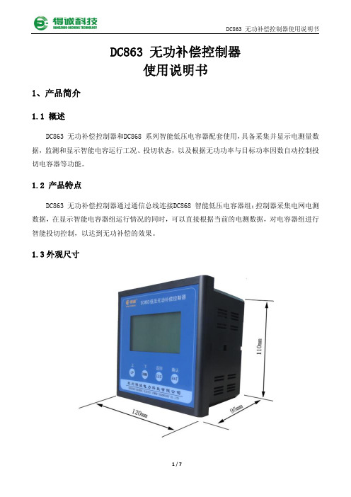
注:
表示分补 表示共补
3/7
DC863 无功补偿控制器使用说明书
表示投入 表示切除
3.2 运行工况
显示开关故障、过压保护、过流保护、过温保护、过谐波保护的电容器信息。
使用 和
3.3 设置参数
切换界面查看各种保护与故障,按
键返回主菜单。
设置现场的电流互感器变比和无功控制的目标功率因数,如果现场互感器变比值不详可以 选择“自动检测 CT„”,自检 CT 必须保证至少有 1 台电容器和控制器联网,如果选中“自动
DC863 无功补偿控制器使用说明书
4.3 DC863无功补偿控制器接线端口说明
Ua,Ub,Uc分别接A,B,C三相电压,Un接零线; Ia+,Ia-,Ib+,Ib-,Ic+,Ic-分别接A,B,C三相电流; A,B为备用485通信接口;
7/7
尺寸
3 、使用说明
DC863 无功补偿控制器使用说明书
分辨率 128×64,显示 12 点阵汉字 RJ45 方式接入智能电容器网络 AC 380V±30% ≤2W -10~55 ℃,相对湿度≤93% 无腐蚀气体场所,海拔≤2000m 电源>2500V ≥2MΩ 面框尺寸:120mm×120mm 开孔尺寸:113mm×113mm
DC863 无功补偿控制器通过通信总线连接DC868 智能低压电容器组;控制器采集电网电测 数据,在显示智能电容器组运行情况的同时,可以直接根据当前的电测数据,对电容器组进行 智能投切控制,以达到无功补偿的效果。
1.3 外观尺寸
1/7
2
工作范围 功耗
工作条件
隔离耐压 绝缘电阻
投切状态
所有电容器投切状态总览
运行工况
DC-DC模块电源应用手册

DC/DC 模块电源 应用手册广州德励电子科技有限公司二零零七年三月二十二日目 录一、基本术语解释 (1)输入电压范围(Input Voltage Range) (1)负载电压调整率(Load Voltage Regulation) (1)输入(线性)电压调整率(Line Voltage Regulation) (1)输出电压精度(Ouput Voltage Accuracy) (1)输入和输出波纹电压(Input and Output Ripple) (1)输入与输出隔离电压(Input to Output Isolation) (1)绝缘阻抗(Insulation Resistance) (1)全负载效率(Efficiency at Full Load) (1)温度漂移(Temperature Drift) (1)温升(Temperature above Ambient) (1)开关频率(Switching Frequency) (1)空载功耗(No Load Power consumption) (1)隔离电容(Isolation Capacitance) (1)平均无故障时间(Mean Time Between Failure)[MTBF] (1)躁声(Noise) (1)工作温度范围(Operating temperature range) (2)二、电源的设计及选用 (3)确定电源规格 (3)系统配电设计 (4)三、电源的测试 (7)开尔文四端测试法 (7)模块的性能 (7)四、电源的应用 (11)隔离(Isolation) (11)串联使用(Connecting DC/DC Converters in Series) (11)并联使用(Connecting DC/DC Converters in Parallel) (11)模块并联使用的推荐值 (12)滤波(Filtering) (12)输出滤波计算 (12)限制涌浪电流(Limiting Inrush Current) (13)容性负载 (13)隔离电容和漏电流 (13)过载保护 (14)输入欠压保护 (15)无负载过压上锁 (15)输入短路保护 (15)EIA-232接口 (16)隔离数据采集系统 (16)远距离传输 (16)减小噪声 (17)电磁兼容 (17)一、 基本术语解释输入电压范围(Input Voltage Range)指产品维持正常工作性能所能容忍的输入电压波动范围。
智能电容器使用说明书(改)
0.45-10(7%)
450*130*370
180*2*140
0.45-7.5(7%) 450*130*370
180*2*140
三 元ቤተ መጻሕፍቲ ባይዱ器件特点
1. 监控单元
采用专用智能控制器及传感元器件,对用电系统及补偿支路和电容器内部的各种数据信息,进行
采集、计算、分析、判断,并发出电容器投、切及各种保护预警、动作等的操作指令。 2. 温度采集单元
0
FKZC 系列—智能电力电容器--使用说明书
诚挚地感谢您选用“沈阳市法克电气有限公司”的智能电容器产品。 请您在安装使用本产品之前详细的阅读本手册,以免造成误操作。 这将为您节约宝贵的时间。
特别声明:由于产品升级、版本更新,本手册所述内容可能无法完全涵盖。如有错误、遗漏等不
当之处,敬请各位用户谅解。
外型尺寸 L*W*H
325*130*420 325*130*390 325*130*390 325*130*390 325*130*390 325*130*390 325*130*390 325*130*390 325*130*390 325*130*340 325*130*340 325*130*340 325*130*340 325*130*340 325*130**330 325*130**330 325*130**330 325*130*390 325*130*390
采用温度传感器件对电容器内部温度进行采集,为监控单元判断电容器的运行状态提供依据。 3. 谐波保护采集单元
采用专用智能控制器取用系统电流互感器对系统的谐波电流及电容器工作电压数据进行采集,为
监控单元进行基波电压电流、谐波电压电流等参数的计算,进行谐波保护提供依据。
直流电源用户手册-按键版
精品欢迎使用本公司电源产品请务必仔细阅读《用户操作手册》以便于用户更加快捷、安全地操作该设备直流电源用户操作手册导言本手册提供给使用者产品参数、选型、安装、故障诊断与排除、日常维护的相关注意事项及指导。
为了确保正确地安装与操作本电源,请在使用之前,认真阅读本手册,并请妥善保存以备后用。
设备配套客户请将此手册随设备交由该电源的最终使用者。
开箱时,请认真核对本机铭牌的型号及额定值是否与您的订货一致。
箱内含您订购的机器、钥匙、产品合格证、用户操作手册、保修卡等。
开箱后,请检查产品在运输过程中是否有破损现象。
若发现有某种遗漏或损坏,请速与本公司或您的供货商联系解决对于初次使用本产品的用户,应先认真阅读本手册。
若对一些功能及性能方面有所疑惑,请咨询我公司的技术支持人员,以获得帮助,对正确使用本产品有利。
由于致力于直流电源的不断改善,因此本公司所提供的资料如有变更,恕不另行通知。
特别声明禁止对本手册内容的全部或任何部份进行未经授权的转换或复制。
本公司已尽可能地保证本册中包含的内容正确无误,如发现有任何错误或遗漏,请与制造商或经销商联系。
本公司对由于未按此手册要求操作而引起的任何直接或间接的损失将不承担任何责任。
电源编号为本公司记录档案代码,用户务必妥善保存,以便我们做好售后服务工作。
本手册使用以下符号表示重要信息,应遵照由这些符号指出的说明进行操作安全及注意事项为了保障操作者的人身安全,请务必在操作电源时注意以下事项直須电源在损坏或者有缺失器件的情况下,请不要使用。
存在造成人身安全或引发严重事故的隐患。
注意电源不可安装在周围有纤维、纸片、木屑以及金属屑的环境,存在损坏电源以及引发重大事故的风险。
土勺为了保障电源可靠运行,距离电源50cm范围内不能存在阻碍电源通风散热的遮挡物。
上也电源布线以及连接应由专业电气工程人员来操作。
上岂接线前请确认电源处于关断状态。
否则可能造成电源损坏或引发重大事故否则会造成电源损坏或引发重大事故土兰T请确认电源电压等级是否和电源额定电压一致;输入、输出的接线位置是否正确,并注意检查外围电路中是否有短路现象。
智能电容控制器说明书-A

智能电容控制器说明书-A3.运行工况界面运行工况里包含了配电电压、电流、功率因数、功率、电压各次谐波、电流各次谐波等各电参数的数值显示,以及测控仪与智能电容器的通信状况,通过“或”键切换界面查看各电参数以及测控仪与智能电容器的通信状况,按“”键返回到主菜单界面。
以下细分界面依次对各项进行介绍:(1)配电三相功率因数、电压、电流界面在使用过程中若出现过补偿或配电电流接线接反,则在上述界面中功率因数数值前显示‘-’,例如A相功率因数显示‘-0.960’,表示此时A相电容已过补偿或A相配电电流方向接反。
在使用过程中若出现过压或欠压现象,在上述界面中电压反显显示,例如A 相电压显示“”,表示此时A相电压已超过设定过压值。
(2)有功、无功、电容电流界面(3)通信界面测控仪与不同的智能电容器通讯,其显示的通信界面略有不同,如下图所示:图1图2图3图1为测控仪与三相式智能电容器或智能抑谐式电容器(双电容电抗)通信界面;图2为测控仪与三相式智能抑谐式电容器(单电容电抗)的通信界面;图3为测控仪与分相式智能电容器5 6P(KW) :实时的有功功率;Q(Kvar):系统当前过补偿或欠补偿的无功数值;C-I(A) :实时的电容器电流值。
的通信界面;“JH C1 C2”中“JH”表示三相式智能电容器的地址,“C1 C2”分别表示内部两组电容器的容量(如图所示“060 20.20”表示此三相式智能电容器地址为“60”,容量为20 Kvar +20Kvar)。
“JH C”中“JH”表示三相式智能抑谐式电容器(单电容电抗)的地址,“C”表示电容器的容量(如图所示“060 40”表示此三相式智能抑谐式电容器(单电容电抗)地址为“60”,容量为40 Kvar)。
“JH A B C”表示分相式智能电容器的地址及A、B、C三相容量(如图所示“06 6.6 6.6 6.6”表示此分相式智能电容器地址为6,电容器容量为20Kvar)。
智能电容器投入后,状态反显显示。
F868使用说明书
F868使用说明书2.4GHz无线影音监控&遥控接收机&多媒体播放器安全说明-.本产品使用微电脑晶片控制,在你使用次产品之前,请认真阅读说明书他会让你享受到本机的各种功能,为你提供更方便的使用.-如果电池电量不足﹐在录制音视频或传输档案时可能会导致严重的系统错误,导致资料丢失.-切误打开机壳! 否则会有触电危险!触摸直流转换的部件可能会导致触电.为防止在使用直流转换器时出现操作问题,请阅读(使用说明书)-注意:-避免使用本产品接触水或者其它液体,否则会有触电或者发生火灾的危险!为了你的安全,请使用本产品提供的电源转换器(对于因使用非提供的转换器而导致产品损坏,制造商概不负责)注意事项请谨使用与转换器相符的插座,否则会有触电或发生火灾的危险﹐将直流转换器的插头稳固地插入电源插座.安全说明:-切勿使用已损坏的充电电池或充电器.-切勿使充电电池的充电时间超过规定时间.-在第一次使用电池或电池在几个月末使用后重新使用时,请为电池完全充电.-为电池完全充电,使用到其完全放电,然后重新为其充电以确保较长的使用寿命,在此情况下,请反复为电池完全充电再完全放电几次,这样你的电池可以使用较长的时间.-过度充电或者过度放电会缩短充电电池的使用寿命.-当充电电池的使用时间明显比新充电电池的使用时间短时,请更换新的充电电池-由于充电电池是消耗品,所以电池的使用时间会随着使用时间而缩短.-小心不要让任何导体(如项链,手镯等)使用直流转换器的接端或充电电池短路,否则可能触电或者引起火灾.1.基本配置l接收频率: CH1:2414MHz;CH2:2432MHz;CH3:2450MH Z;CH4:2468MHzl接收灵敏度:-90dBml LCD:640×240 高清晰TFT LCDl PMP Play:支持MPEG、AVI、ASF、MP3、WAVl AV输入录像: Voice:WAV,Samples per second:64kHz;VIDEO recording:MPEG4,ASFl AV输出: TV PAL/NTSC 音视频l支持JPEG 图片浏览l无线移动录像功能l内置128M Flash,外置SD Card 插口l支持USB2.0与PC双向数据传输l内置麦克风l内置喇叭l电源:3.7V Li-Battery, DC 5V电源充电1.整机示意图⒇ (15 )⑥⑦⑧⑨⑩⑿⑾⒁⒀⒃①④③⒆②⒅⒄(21)(22)○1〝ON OFF〞:开机/关机按钮,按住3秒以上开机或关机.②电源插座,使用外部电源供电或充电.③USB插座,使用USB线连接PC.④RESET:复位按钮.⑤显示屏幕.⑥〝CH〞按钮: 频到转换按钮.⑦〝REC〞按钮: 视频录制启动按钮.⑧〝MENU〞按钮:菜单按钮,菜单、PMP模式显示/关闭时间、删除文件.⑨〝ESC〞按钮:退出按钮.⑩〝▲〞按钮:选择菜单、上选择、音量加.云台控制上旋转。
无功补偿控制器说明书
NAD-868系列低压无功补偿控制器使用说明书杭州南德电气有限公司概述产品外形美观大方,安装使用方便。
通过数码管显示和按键实现人机对话。
通过485通讯与NAD-868系列智能电容器连接。
控制物理量为电压、电流、功率因素和无功功率复合型。
采用新型的无功趋势潮流判断算法,特别适用于功率因数变动大的场合。
动作次数少,控制精度高。
一、功能特点1)动态显示配电的各个参数值,参数设置简单快捷,设置的参数断电不丢失。
2)自动检测智能电容器数量及容量等信息,并按电网无功参数控制智能电容器投切。
3)具有过压、欠压、欠流、过温、电压电流谐波保护,当电网参数超过各设定限制时,控制器快速切除已投入的电容器,并闭锁输出,保护电容器安全运行,延长其使用寿命。
4)采用电压、电流,功率因数,无功等综合计算,电压回差参与控制判断,使补偿更精确,防止投切振荡。
5)在动作延时时间内多点采样上述判据值,根据各点的值来进行无功趋势潮流判断,避免了常规控制器的动作点单点采样所造成的判断失常,在功率因数变动大的场合,可以准确判断所需补偿的无功功率及补偿方向(投或是切)。
6)具有手动/自动切换功能。
置自动时,根据电压、负荷、功率因数和无功缺额综合因素控制电容器的投入或切除;置手动时,能手动操作电容器的投入或切除,便于出厂调试及快速投切电容。
7)投切原则:相同容量的电容器按投切次数动作,动作次数最少的先动作,不同容量的电容器按无功缺额动作.二、产品型号NAD -868C 口口显示方式:E-数码管,Y-液晶补偿方式:S:共补H:混补产品系列号企业代号二、使用环境相对湿度:20%~90%;环境温度:-25~70℃;海拔高度:≤2000m;无易燃的介质存在,无导电尘埃及腐蚀性气体存在。
三、技术参数1)测量精度:电 压:≤±0.5%(在80%~120%额定电压范围内);电 流:≤±1.0%(在50%~100%额定电流范围内);功率因数:≤±1.5%无功功率:≤±2%温 度:≤1℃2)输出方式:通讯式控制输出,控制本公司智能电容器。
智能电容器说明书

C1
C2
C1
C2
B 相 二 次 侧 电 流 电容器 C1 温度, A 相电容器电流,
AC 相电压(V),
C 相电容器电流,
值(A),总无功 电 容 器 C2 温 度 B 相 电 容 器 电 流
功率因数
拉合闸错误码
功率(kvar) (℃)
(A)
序号 6
7
8
9
10
显示
Uac(V)
图例
A
00 1 7h - 0.0 7h - 0.0 e Ib(A)
门槛
门槛
(mA)
图例 08、09(过压保护)注:
电压超过一级保护值时,电容器不投不切、停止动作响应, 电压超过二级保护值时,已投电容器逐一自动切除、退出工作。
序号 16 显示
图例 16
090
描述 电容放电时间(S)
图例 06(本机地址)注:
在图例 06 界面时,按
键,直接跳过即可,为系统自动组网状态。
6 电源线连接说明
分补型
(220V 指示灯)
总容量 多芯铜导线
1~19 kvar 10mm2
20~39 kvar 16mm2
40~70 kvar 25mm2
务必注意: 拧紧螺丝,用力拉电源线,确保连接十分牢固方可使用。 否则接线端会过度发热,导致产品损坏。
分补型 必须接零线,线径规格同三相电源进线。
分补型 P9 页,界面“ 04 - 100 ” 互感器变比值设置。设置完后系统进入自动运行状态。
-5-
9.1 液晶式共补型操作界面说明
1
234
智能组合式低压 电力电容补偿装置
Uac(v)
CosΦ
5
6
DC868RS和DC868RF常规型智能低压电容器
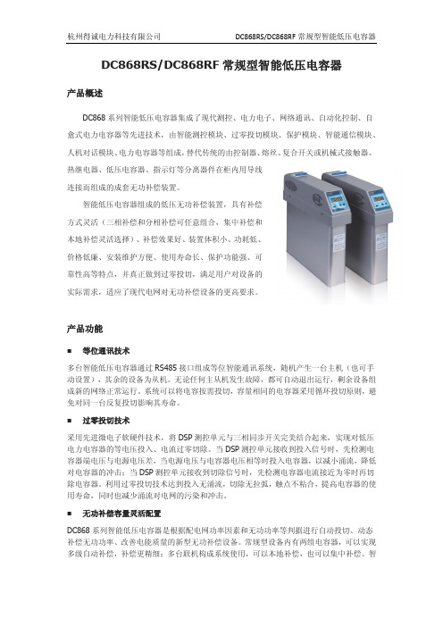
DC868RS/DC868RF常规型智能低压电容器产品概述DC868系列智能低压电容器集成了现代测控、电力电子、网络通讯、自动化控制、自愈式电力电容器等先进技术,由智能测控模块、过零投切模块、保护模块、智能通信模块、人机对话模块、电力电容器等组成,替代传统的由控制器、熔丝、复合开关或机械式接触器、热继电器、低压电容器、指示灯等分离器件在柜内用导线连接而组成的成套无功补偿装置。
智能低压电容器组成的低压无功补偿装置,具有补偿方式灵活(三相补偿和分相补偿可任意组合,集中补偿和本地补偿灵活选择)、补偿效果好、装置体积小、功耗低、价格低廉、安装维护方便、使用寿命长、保护功能强、可靠性高等特点,并真正做到过零投切,满足用户对设备的实际需求,适应了现代电网对无功补偿设备的更高要求。
产品功能■等位通讯技术多台智能低压电容器通过RS485接口组成等位智能通讯系统,随机产生一台主机(也可手动设置),其余的设备为从机。
无论任何主从机发生故障,都可自动退出运行,剩余设备组成新的网络正常运行。
系统可以将电容按需投切,容量相同的电容器采用循环投切原则,避免对同一台反复投切影响其寿命。
■过零投切技术采用先进微电子软硬件技术,将DSP测控单元与三相同步开关完美结合起来,实现对低压电力电容器的等电压投入、电流过零切除。
当DSP测控单元接收到投入信号时,先检测电容器端电压与电源电压差,当电源电压与电容器电压相等时投入电容器,以减小涌流,降低对电容器的冲击;当DSP测控单元接收到切除信号时,先检测电容器电流接近为零时再切除电容器。
利用过零投切技术达到投入无涌流,切除无拉弧,触点不粘合,提高电容器的使用寿命,同时也减少涌流对电网的污染和冲击。
■无功补偿容量灵活配置DC868系列智能低压电容器是根据配电网功率因素和无功功率等判据进行自动投切、动态补偿无功功率、改善电能质量的新型无功补偿设备。
常规型设备内有两组电容器,可以实现多级自动补偿,补偿更精细;多台联机构成系统使用,可以本地补偿,也可以集中补偿。
DCDC-20A DC到DC双电池充电器用户手册说明书

DCDC-20ADC to DC Dual Battery ChargerUser ManualImportant Safety Instructions& WARNING!To avoid any personal injury, please read the safety instructions below. This battery charger is not intended for use by children or infirm persons without supervision.FOR AUTOMOTIVE AND RECREATIONAL VEHICLE 12V DEEP CYCLE BATTERY USE ONLY.NOT TO BE USED WITH DRY CELL BATTERIES.•During the charging process, do not use a naked flame near a battery. Batteries generate explosive gasses during the charging process that may explode.•Never smoke or light cigarettes near a battery.•Do not place tools on top of a battery or allow tools to fall on the battery to prevent the chance of a short circuit and sparks.•Always wear eye protection when charging a battery.•Ensure charging and testing is conducted in a well-ventilated area.•Inadequate ventilation may over-heat the charger and cause in-efficient operation .•This battery charger is not intended for outdoor operation. Do not expose it to moisture or extreme weather conditions.•The ACID/FLUID within a battery is highly corrosive and poisonous. It can produce flammable and toxic gases when recharged and will explode if ignited. When working with batteries, always wear eye protection, remove jewellery and ensure the area is well ventilated. If spilt -it will cause severe burning to eyes, skin, clothing, damage paintwork and corrode many metals. Ensure that power is disconnected from any appliance in the vicinity of the spill and immediately wash any area that has been affected with water.The warnings, cautions and instructions detailed in this instruction manual cannot cover all possible conditions and situations that may occur. Common sense and caution are factors which cannot be built into this product and must be supplied by the operator.Page 01DCDC-20A Acid, LiONUsing the twin core wiring laid between the main starting battery and the charger, connect the (+) of the starting battery to the (+) red charger wire (DC INPUT), and the (-) of the starting battery to the (-) of the starting battery to the (-) shared negative wire (GROUND) of the charger. Finally, connect the solar panel wires to the charger as per the diagram, as well as the optional ACC wire (if required).Ensure unused cables (e.g. ACC wire) are insulated and secured against movement. Check all connections are tight.Suggested installation to vehicle only。
电容使用说明
电容使用说明电容器是一种储能组件,具有“隔直通交,阴低频通高频”的特性,人们为了认识和鉴别不同电路中的电容器,根据其在线路中的作用而给它起了许多名称,了解这些名称和作用,对读图是垫脚有帮助的。
下面介绍一些常用名称的含义。
1、滤波电容它并接在电路正负极之间,把电路中无用的交流电流去掉,一般采用大容量电解电容器,也有采用其他固定电容器的。
2、退耦电容并接于电路正负极之间,可防止电路通过电源内阻形成的正反馈通路而引起的寄生振荡。
3 、耦合电容连接于信号源和信号处理电路或两级放大器之间,用以隔断直流电,让交流电或脉动信号通过,使相信的放大器直流工作点互不影响。
4、旁路电容并接在电阻两端或由某点直接跨接至共享电信为交直流信号中的交流或脉动信号设置一条通路,避免交流成分在通过电阻时产生压降。
5、中和电容连接于三极管基极与集电极之间,用于克服三极管极间电容而引起的自激振荡。
6、槽路电容(调谐电容)连接于谐振电路或振荡电路线圈两端的电容。
7、垫整电容在电路在能使振荡信号的频率范围减小,而且显着提高低频端振荡频率的电容,它是与槽路主电容串联的。
8、补偿电容在振荡电路中,能使振荡信号的频率范围得到扩大的电容,它与主电容并联起辅助作用。
9、逆程电容并接在行输出管集电极与发射极之间,用来产生行扫描锯齿波逆程的电容。
10、自举升压电容利用其储能来提升电路由某的电位,使其电位值高于为该点供电的电源电压。
11、“S”校正电容串接于偏转线圈回路中,用于校正两边延伸失真。
12、稳频电容在振荡电路中,用来稳定振荡频率的电容。
13、定时电容在RC定时电路中与电阻R串联共同决定时间长短的电容。
14、降压限流电容串接于交流电路中用于它对交流电的容抗进行分压限流。
15、缩短电容这种电容是在UHF高频头中为了缩短振荡电感的长度而串接的电容。
16、克拉泼电容在电容三点式振荡电路中,串接在振荡电感线圈的电容,为了水运晶体管结电容的影响,提高频率稳定性。
DC868XRS和DC868XRF抗谐波型智能低压电容器

20
525
三相
DC868XRS/525-15-14%
15
525
补偿
DC868XRS/525-10-14%
10
525
DC868XRS/525-5-14%
5
525
DC868XRF/300-20-14%
20
300
分相
DC868XRF/300-15-14%
15
300
补偿
DC86位通讯,可组成智能网络管控设备,也可与外界通讯; ■ 采用无涌流同步开关,技术先进,性能稳定可靠; ■ 采用特殊的技术与工艺,能有效的抑制高次谐波和涌流,抑制 3~21 次谐波效果明显; ■ 模块化结构,组合灵活,安装简单,扩容方便,便于维护; ■ 采用分散控制模式,50 万次无故障投切,可靠性高; ■ 采用高品质工业型低压自愈式电力电容器,安全性高; ■ 内加 SH 防爆器及温控装置,提高严重谐波场所下的运行可靠性; ■ 采用闭环电路,磁路不饱和,无能源消耗,无电磁辐射; ■ 人性化的人机界面,操作简单,维护方便,利于现场故障查找; ■ 节能效果显著,精确提高功率因数,降低电能功耗,改善电能质量。
DC868XRS/DC868XRF 抗谐波型智能低压电容器
产品概述
DC868X 系列抗谐波型智能低压电容器是应用于低压配电网中的高效节能、抑制谐波、 提高功率因数的新一代无功补偿设备。该系列产品是针对用电网络谐波含量较高,常规智能 低压电容器不能正常运行的情况下而设计的。主要应用在电流谐波含有率低于 50%的场所, 既能满足无功补偿、改善功率因数,又能降低高次谐波对电力系统的影响,提高用电质量。
杭州得诚电力科技有限公司dc868xrsdc868xrf抗谐波型智能低压电容器技术参数电气安全电气间隙与爬电距离绝缘强度安全防护短路强度采样与控制电路防护均符合中华人民共和国电力行业标准dlt8422003低压并联电容器装置使用技术条件中对应条款要环境条件环境温度
电子产品教程:电容器充电与放电说明书

ElectricityDC and AC circuitsCharging and Discharging a CapacitorINVESTIGATION OF HOW THE VOLTAGE ACROSS A CAPACITOR CHANGES OVER TIME WHEN THE CAPACITOR IS CHARGING OR DIS-CHARGING.UE3050101 10/15 UDFig. 1: Measurement set-up.GENERAL PRINCIPLESIn a DC circuit, current only flows through a capacitor at the point in time when the power is turned on or off. The current causes the capacitor to charge up until the volt-age across it is equal to the voltage applied. When the power is switched off, the capacitor will discharge till the voltage across it drops to zero. A plot of the capacitor voltage against time can be shown as an exponential curve.For a DC circuit featuring a capacitance C , resistance R and a DC voltage U 0, the following applies when the supply is turned on:(1) 1/20ln 2()(1)t T U t U e⋅-=⋅-The following applies when the power supply is switched off: (2) 1/20ln 2()t T U t U e ⋅-=⋅.where(3) 1/2ln2T R C =⋅⋅T 1/2 is the half-life period, i.e. the voltage across a discharging capacitor will halve within a time T 1/2. The same period elaps-es when the voltage drops from a half to a quarter and from a quarter to an eighth.These aspects will be investigated in the experiment. How the capacitor voltage changes over time is recorded using a stor-age oscilloscope. Since the DC voltage U 0 is set to 8 V, it is easy to read off a half, a quarter and an eighth of that value.LIST OF EQUIPMENT1 Plug-In Board for Components U33250 10129021 Resistor 470 Ω,2 W U333022 10129141 Resistor 1 kΩ,2 W U333024 10129161 Resistor 2,2 Ω, 2 W U333026 10129183 Capacitor 1 µF, 100 V U333063 10129551 Function Generator FG 100 U8533600 1009956/71 USB Oscilloscope, 2x50 MHz U112491 10172642 HF Patch Cord,BNC/4 mm Plug U11257 10027481 Set of 15 Experiment Leads U13800 10028411 Set of 10 Jumpers U333093 1012985 Additionally required:1 Computer running Win XP, Vista or Win7 operating sys-temSET-UP AND PROCEDURE∙Set up the apparatus for the measurement as shown in Fig. 2.∙Set up the circuit shown in Fig. 3 on the plug-in board.∙For the oscilloscope, select a time base of 1 ms, 1 V for the vertical deflection of CH1 and CH2, set the trigger mode to edge and and trigger sweep to auto. The source of the trigger should be CH1 and with a threshold of around 600 mV.Fig. 3: Sketch of circuit.Time to reach half-way when charging and discharging∙Plug a resistor of 1 kΩ and a capacitor of 1 µF into the plug-in board as sketched in Figs. 2 and 3.∙Set s frequency of 100 Hz on the function generator and selct a square waveform.∙Select an amplitude which will result in a signal with a peak to peak voltage U = 8 V, corresponding to ±4 divi-sions with a setting of 1 V/div.∙Read off from the oscilloscope the times T1/2 it takes the voltage to halve as the capacitor discharges from voltag-es of U = 8 V down to U = 4 V, from U = 4 V down to U = 2 V and from U = 2 V down to U = 1 V and enter these values into Table 1.∙Read off from the oscilloscope the times T1/2 it takes the voltage to reach the various half-way points when charg-ing up to U = 8 V, i.e. U = 0 V up to U = 4 V, U = 4 V to U = 6 V and U = 6 V to U = 7 V. Enter these values into Table 2.Fig. 2: Sketch of measurement set-up.Half-way values for a fixed capacitor∙Use two capacitors with capcitance C = 1 µF in parallel to create a network with capacitance C = 0.5 µF.∙Set up circuits with resistance values of R = 0.47, 1, 1.47,2.2 und 2.67 kΩin succession. For those values whichcannot be achieved using a single resistor, use two resis-tors in series.∙For each of these resistance values R, read off from the oscilloscope the time T1/2its takes the voltage value to reach half way and enter the results into Table 3.Half-way values for a fixed resistor∙Use an ohmic resistor of value R = 470 Ω.∙Set up circuits with capacitance values of C = 0.33, 0,5,0.67, 1, 1.5 und 2 μF in succession. For those valueswhich cannot be achieved using a single capacitor, use multiple capacitors of value C = 1 µF in series or parallel. ∙For each of these capacitance values,read off from the oscilloscope the time T1/2its takes the voltage value to reach half way and enter the results into Table 4. SAMPLE MEASUREMENTFig. 4 shows an example oscilloscope trace for the charging and discharging of a capacitor. The yellow exhibits how the voltage across the ohmic resistance changes with time (CH1), while the blue curve represents the change in voltage across the capacitance (CH2).Fig. 4: Traces of voltage across a capacitor while charging and discharging recorded with an oscilloscope. Tab. 1: Times T1/2 for voltages to halve when a capacitor C =1 µF discharges through a resistor R = 1 kΩTab. 2: Times T1/2 for voltage to reach half way when a ca-pacitor C = 1 µF charges via a resistor R = 1 kΩTab. 3: T imes T1/2 for voltage to reach half way when a ca-pacitor C = 0.5 µF charges or discharges in circuitswith various resistance values R.Tab. 4: T imes T1/2 for voltage to reach half way when a ca-pacitors C charge or discharge in circuits with a fixedresistance R = 470 Ω.EVALUATIONHalf-way values when charging and dischargingThe agreement between the times it takes voltage to reach half way at various parts of the charging and discharging curves (Tables 1 and 2) confirms the expected exponential relationship, see equations (1) and (2).Half-way value for a fixed capacitor∙Plot the “half-way” values T1/2from Table 3 against the resistance R on a graph and join up the points with a straight line through the origin (Fig. 5).∙To verify equation (3), determine the capacitance C from the gradient of the line m C.(4) =⋅1/2CT m R where =⋅Cln2m CC0.330.48Fln2ln2mC⇒=μ==.The value determined by measurement is very well in agree-ment with the nominal capacitance value C = 0.5 μF.3B Scientific GmbH, Rudorffweg 8, 21031 Hamburg, Germany, 123R / k ΩT 1/2 / msFig. 5: Half-life T 1/2 as a function of resistance R .Half-way value for a fixed resistor ∙Plot the “half -way” values T 1/2 from Table 4 against the capacitance C on a graph and join up the points with a straight line through the origin (Fig. 6).∙To verify equation (3), determine the resistance R from the gradient of the line m R .(5) =⋅1/2R T m C where =⋅R ln2m RR 0.320.46k ln2ln2m R ⇒=Ω==.The value determined by measurement is very well in agree-ment with the nominal resistance value R = 470 Ω. ∙Multiply the values for the ohmic resistance R from Table. 3 with that of the capacitance C = 0.5 µF and alsoi multi-ply the capcitance values C from Table 4 with the re-sistance value R = 470 Ω. Enter these values for the product R ·C alongside the corres ponding “half -way” from Tables 3 and 4 into Table 5.Tab. 5: H alf-way times T 1/2 for products R ·C , as calculatedfrom the values in Rables 3 und 4.∙Plot the “half -way times T 1/2 fromTable 5 against the prodcts R ·C on a grph and join the points with a straight line through the origin (Fig. 5).∙To verify equation (3), determine the resistance use the gradient of the line m to determine that the coefficient of proportionality is ln2.(6) =⋅⋅1/2T m R C where =ln 2mThe value obtained by measurement m = 0.67 is very well in agreement with the theoretical value ln2 = 0.69.12T 1/2 / ms C / FμFig. 6: Half-life T 1/2 as a function of capacitance C .10T 1/2 / ms RC / msFig. 7: Half-life T 1/2 as a function of the product of R *C .。
美国埃拉迪电子产品有限公司 DC-Link 电容器说明书

Dimensions: [mm]MDBP375156JA10DCPP15040890734428004CSMDBP375156JA10DCPP15040 890734428004CSMDBP375156JA10DCPP15040 890734428004CSMDBP375156JA10DCPP15040 890734428004CST e m p e r a t u r eT T T MDBP375156JA10DCPP15040890734428004CSCautions and Warnings:The following conditions apply to all goods within the product series of Film Capacitors of Würth Elektronik eiSos GmbH & Co. KG:General:•This electronic component is designed and manufactured for use in general electronic equipment.•Würth Elektronik must be asked for a written approval (following the certain PPAP level procedure) before incorporating the components into any equipment in the field such as military, aerospace, aviation, nuclear control, submarine, transportation (automotive control, train control, ship control), transportation signal, disaster prevention, medical, public information network etc. where higher safety and reliability are especially required and/or if there is the possibility of direct damage or human injury.•Electronic components that will be used in safety-critical or high-reliability applications, should be pre-evaluated by the customer. •Direct mechanical impact to the product shall be prevented as material of the body, pins or termination could flake or in the worst case it could break.•Avoid any water or heavy dust on capacitors surface, which may cause electrical leakage, damage, overheating or corrosion.•Würth Elektronik products are qualified according to international standards, which are listed in each product reliability report. Würth Elektronik does not warrant any customer qualified product characteristic, beyond Würth Elektronik specifications, for its validity and sustainability over time.•The customer is responsible for the functionality of his or her own products. All technical specifications for standard products also apply to customer specific products.•The component is designed and manufactured to be used within the datasheet specified values. If the usage and operation conditions specified in the datasheet are not met, the body, pins or termination may be damaged or dissolved.•Do not apply any kind of flexural or compressive force onto soldered or unsoldered component.•The capacitance tolerance as specified within the datasheet is only valid on the date of delivery and according specified measurement criteria.Product specificStorage conditions• A storage of Würth Elektronik products for longer than 12 months is not recommended. Within other effects, the terminals may suffer degradation, resulting in bad solderability. Therefore, all products shall be used within the period of 12 months based on the day of shipment.•Do not expose the components into direct sunlight.•The storage condition in the original packaging is defined according to DIN EN 61760-2.•The environment in which the capacitors are operated and stored has to have atmospheric characteristics and must be free of dew condensation and toxic gases (e.g. chlorine, ammonia, sulfur, hydrogen sulphide and hydrogen sulfate).•Do not expose the capacitor to environments with hazardous gas, ozone, ultraviolet rays or any kind of radiation. Avoid any contact of the capacitor with direct sunshine, saltwater, spray of water or types of oil during storage. •The storage conditions stated in the original packaging apply to the storage time and not to the transportation time of the components. Operating climatic conditions•Do not exceed the lower nor the upper specified temperature under no circumstances.•Do not use the capacitors under high humidity, high temperature or under high or low atmospheric pressure which may affect capacitors reliability.•Surface temperature including self-heating must be kept below the maximum operating temperature.Operating load conditions•Due to self-heating the reliability of the capacitor may be reduced, if high frequency AC or pulse is applied.•Consider carefully possible specific changes of electrical characteristics like capacitance over temperature, voltage and time as well as the specific performance over frequency for the actual use conditions.•Avoid any overvoltage and do not apply a continuous overvoltage. If an overvoltage is applied to the capacitor, the leakage current can increase drastically. The applied working voltage is not allowed to exceed the rated working voltage of the specific capacitor.•If film capacitors with safety approvals are operated with a DC voltage exceeding the specified AC voltage, the approvals given on the basis of IEC 60384-14 are no longer valid.•For the WCAP-FTDB film capacitor the maximum peak voltage Vpeak+ shall not be greater than the rated voltage VR according to the temperature derating of the rated voltage VR. The peak-to-peak value of the ripple voltage Vp-p should not be greater than 0.3*VR according to the temperature derating of the rated voltage VR. The rated voltage of the capacitor may need to be reduced for different operating temperatures. See voltage derating curve within this datasheet.Packaging:•The packaging specifications apply only to purchase orders comprising whole packaging units. If the ordered quantity exceeds or is lower than the specified packaging unit, packaging in accordance with the packaging specifications cannot be ensured. Soldering•The solder profile must comply with the Würth Elektronik technical soldering specification. All other profiles will void the warranty. •All other soldering methods are at the customer’s own risk.•Strong forces which may affect the coplanarity of the component’s electrical connection with the PCB (i.e. pins), can damage the part, resulting in void of the warranty.•Customer needs to ensure that the applied solder paste, the paste thickness and solder conditions are enough to guarantee a sufficient solder result according to the relevant criteria of IPC-A-610.•Excessive amount of solder may lead to higher tensile force and chip cracking. Insufficient amount of solder may detach the capacitor due to defective contacts.•Do not use excessive nor insufficient flux.Würth Elektronik eiSos GmbH & Co. KGEMC & Inductive SolutionsMax-Eyth-Str. 174638 WaldenburgGermanyCHECKED REVISION DATE (YYYY-MM-DD)GENERAL TOLERANCE PROJECTIONMETHODFPu001.0002022-10-13DIN ISO 2768-1mDESCRIPTION TECHNICAL REFERENCEWCAP-FTDB DC-Link Capacitor MDBP375156JA10DCPP15040ORDER CODE890734428004CSSIZE/TYPE BUSINESS UNIT STATUS PAGECleaning•Do not use any other cleaning solvents for box-typed capacitors except: ethanol, isopropanol, n-propanol - water mixtures. After cleaning a drying process with temperatures not exceeding 65°C and not longer than 4 hours is mandatory to prevent any kind of electrical damage.Coating, molding and potting of the PCB•If the product is potted in the costumer’s application, the potting material might shrink or expand during and after hardening. Shrinking could lead to an incomplete seal, allowing contaminants into the body and termination. Expansion could damage the body or termination. We recommend a manual inspection after potting to avoid these effects.•If final assemblies will be placed completely in any plastic resin, physical, chemical and thermal influences must be considered. •When coating and molding the PCB, verify the quality influence on the capacitor.•Verify the curing temperature and assure that there is no harmful decomposing or reaction gas emission during curing. •Do not exceed the specified max. self-heating.Vibration resistance•Do not exceed the vibration limits given by IEC60068-2-6.Handling•After soldering, please pay attention not to bend, twist or distort the PCB in handling and storage. •Avoid excessive pressure during the functional check of the PCB. •Avoid bending stress while breaking the PCB.•WCAP-FTXX and WCAP-FTX2 capacitors are not designed and not recommended to be used in series connection to the mains. •The temperature rise of the component must be taken into consideration. The operating temperature is comprised of ambient temperature and temperature rise of the component.The operating temperature of the component shall not exceed the maximum temperature specified.Flammability•Avoid any external energy or open fire (passive flammability).These cautions and warnings comply with the state of the scientific and technical knowledge and are believed to be accurate and reliable.However, no responsibility is assumed for inaccuracies or incompleteness.(V2.2)Würth Elektronik eiSos GmbH & Co. KG EMC & Inductive Solutions Max-Eyth-Str. 174638 Waldenburg GermanyCHECKED REVISION DATE (YYYY-MM-DD)GENERAL TOLERANCEPROJECTION METHODFPu001.0002022-10-13DIN ISO 2768-1mDESCRIPTIONTECHNICAL REFERENCEWCAP-FTDB DC-Link CapacitorMDBP375156JA10DCPP15040ORDER CODE890734428004CSSIZE/TYPEBUSINESS UNITSTATUSPAGEImportant NotesThe following conditions apply to all goods within the product range of Würth Elektronik eiSos GmbH & Co. KG:1. General Customer ResponsibilitySome goods within the product range of Würth Elektronik eiSos GmbH & Co. KG contain statements regarding general suitability for certain application areas. These statements about suitability are based on our knowledge and experience of typical requirements concerning the areas, serve as general guidance and cannot be estimated as binding statements about the suitability for a customer application. The responsibility for the applicability and use in a particular customer design is always solely within the authority of the customer. Due to this fact it is up to the customer to evaluate, where appropriate to investigate and decide whether the device with the specific product characteristics described in the product specification is valid and suitable for the respective customer application or not.2. Customer Responsibility related to Specific, in particular Safety-Relevant ApplicationsIt has to be clearly pointed out that the possibility of a malfunction of electronic components or failure before the end of the usual lifetime cannot be completely eliminated in the current state of the art, even if the products are operated within the range of the specifications.In certain customer applications requiring a very high level of safety and especially in customer applications in which the malfunction or failure of an electronic component could endanger human life or health it must be ensured by most advanced technological aid of suitable design of the customer application that no injury or damage is caused to third parties in the event of malfunction or failure of an electronic component. Therefore, customer is cautioned to verify that data sheets are current before placing orders. The current data sheets can be downloaded at .3. Best Care and AttentionAny product-specific notes, cautions and warnings must be strictly observed. Any disregard will result in the loss of warranty.4. Customer Support for Product SpecificationsSome products within the product range may contain substances which are subject to restrictions in certain jurisdictions in order to serve specific technical requirements. Necessary information is available on request. In this case the field sales engineer or the internal sales person in charge should be contacted who will be happy to support in this matter.5. Product R&DDue to constant product improvement product specifications may change from time to time. As a standard reporting procedure of the Product Change Notification (PCN) according to the JEDEC-Standard inform about minor and major changes. In case of further queries regarding the PCN, the field sales engineer or the internal sales person in charge should be contacted. The basic responsibility of the customer as per Section 1 and 2 remains unaffected.6. Product Life CycleDue to technical progress and economical evaluation we also reserve the right to discontinue production and delivery of products. As a standard reporting procedure of the Product Termination Notification (PTN) according to the JEDEC-Standard we will inform at an early stage about inevitable product discontinuance. According to this we cannot guarantee that all products within our product range will always be available. Therefore it needs to be verified with the field sales engineer or the internal sales person in charge about the current product availability expectancy before or when the product for application design-in disposal is considered. The approach named above does not apply in the case of individual agreements deviating from the foregoing for customer-specific products.7. Property RightsAll the rights for contractual products produced by Würth Elektronik eiSos GmbH & Co. KG on the basis of ideas, development contracts as well as models or templates that are subject to copyright, patent or commercial protection supplied to the customer will remain with Würth Elektronik eiSos GmbH & Co. KG. Würth Elektronik eiSos GmbH & Co. KG does not warrant or represent that any license, either expressed or implied, is granted under any patent right, copyright, mask work right, or other intellectual property right relating to any combination, application, or process in which Würth Elektronik eiSos GmbH & Co. KG components or services are used.8. General Terms and ConditionsUnless otherwise agreed in individual contracts, all orders are subject to the current version of the “General Terms and Conditions of Würth Elektronik eiSos Group”, last version available at .Würth Elektronik eiSos GmbH & Co. KGEMC & Inductive SolutionsMax-Eyth-Str. 174638 WaldenburgGermanyCHECKED REVISION DATE (YYYY-MM-DD)GENERAL TOLERANCE PROJECTIONMETHODFPu001.0002022-10-13DIN ISO 2768-1mDESCRIPTION TECHNICAL REFERENCEWCAP-FTDB DC-Link Capacitor MDBP375156JA10DCPP15040ORDER CODE890734428004CSSIZE/TYPE BUSINESS UNIT STATUS PAGE。
- 1、下载文档前请自行甄别文档内容的完整性,平台不提供额外的编辑、内容补充、找答案等附加服务。
- 2、"仅部分预览"的文档,不可在线预览部分如存在完整性等问题,可反馈申请退款(可完整预览的文档不适用该条件!)。
- 3、如文档侵犯您的权益,请联系客服反馈,我们会尽快为您处理(人工客服工作时间:9:00-18:30)。
科技创新、节能环保
1
目录
一、 产品概述
二、 产品型号规格和说明
1、 型号说明
2、 常规产品的型号规格
三、 产品外形与安装尺寸 四、 接线端子排列与定义 五、 产品应用电气连接及接线
1、 三相共补接线图
2、 混合补偿接线图
六、 显示面板定义说明 七、 开机前的检查与试验 八、 操作说明
1、 数据查看
2、 参数设定
科技创新、节能环保
2
九、 查看数据界面
1、 三相共补式数据查看说明
2、 单相分补式数据查看说明
十、 参数设定界面
1、 三相共补式参数设定说明
2、 单相分补式参数设定说明
十一、 常见故障分析
1、 通电后产品数码管暗或无显示
2、 PF 值显示负值
3、 故障指示灯亮
科技创新、节能环保
3
一、 产品概述
DC868系列低压智能电容器是应用于0.4kV 低压电网的新一代无功补偿装置。
它由CPU 测控单元、同步开关、保护装置、两台(△型)或一台(Y 型)低压自愈式电力电容器组成一个独立完整的智能补偿单元,替代由智能无功控制器、熔丝(或微断)、晶闸管复合开关(或接触器)、热继电器、指示灯、低压电力电容器多种分散器件组装而成的自动无功补偿装置。
由DC868系列智能电容器组成的低压无功补偿装置具有补偿方式灵活(共补和分补可任意组合)、补偿效果好、装置体积小、功耗低、价格廉、安装维护方便、使用寿命长、保护功能强、可靠性高等特点,并真正做到过零投切,满足用户对无功补偿要切实达到提高功率因数、改善电压质量、节能降损的实际需求。
科技创新、节能环保
4
二、 产品型号说明
1、 型号说明
DC
∕450
二级容量(kvar )
分相补偿只有一级容量 一级容量(kvar) 额定电压(V )
显示方式:Y-液晶显示 数
码显示无字母 补偿方式:S-共补 F-分补 组网方式:R-RS485 L-蓝牙
W-无线 产品系列号:868-通用型
868X-抗谐波型
企业代号:得诚
科技创新、节能环保
5
2、常规产品型号规格
科技创新、节能环保
6
三、 产品外形及安装尺寸
注:高度尺寸见表1
科技创新、节能环保
7
四、 接线端子排列与定义
产品的接线端子分电源端子和测控联机端子,均置于产品的后部,三相补偿电源端子有“UA.UB.UC ”,分相补偿电源端子有:“UA.UB.UC.UN ”,测控联机端子使用插拔件,便于现场调试和调换,产品上有“1.2.3.4.5.6.7.8.9.10.11”,序号标志,其中6—11是标准的6针水晶头接口,两个并接,接线或调换时应充分注意。
产品端子排列见下表:
科技创新、节能环保
8
五、 产品应用电气连接及接线示意图
产品的配线要求:
产品与电源端的连接导线规格:一般情况,单台容量为30kvar 以上的共补
智能电容器和容量20kvar 分补智能电容器,应采用截面积16mm 2
的绝缘多芯铜导
线,其余规格的采用截面积10mm 2
的绝缘多芯铜导线。
电容器与电容器间的信号线连接线规格:信号线包括电流取样线、RS-485
通信线、指示灯线、外控信号输入线等,信号线采用截面积为0.75mm 2
多芯铜导线。
各台电容器之间RS-485通过两个并接的水晶头并接;电流信号线并接后接至DC868-CT 二次电流互感器的输出端。
1、三相共补接线图
(注意:采样电流是B 相电流,要经过DC868-CT 二次电流互感器)
科技创新、节能环保
9
2、混合补偿接线图
(注意:三相电流采样要经过DC868-CT 二次电流互感器)
科技创新、节能环保
10
六、 显示面板定义说明
七、开机前的检查与试验
(1)接线结束并校核确认无误后,用万用表检查三相电源线各相之间及各相与零线之间是否短路,将面板上的拨动开关拨至“自动”位置。
(2)合上空气开关,面板上运行灯应点亮,其余指示灯应不亮, 10秒后,显示“PF ”。
科技创新、节能环保
11
八、操作说明
本产品采用循环显示界面,显示界面分为:数据界面、参数界面和记录界面三种界面,数据界面分为数据名称界面和数据内容界面;参数界面分为参数名称界面和参数内容界面;记录界面分为记录名称界面和记录内容界面;在操作中界面下翻按键只能向前不能后退。
(提示:用户在使用本产品前,尽量熟知三相和分相补偿方式电容器轮显内容里面数据名称代表含义,详见表2、表3。
)
1、 数据查看
查看方法:当开机10秒左右后,系统将自动进入数据界面,连续按“确认”键,共补参数:PF-q-u-Ib-IA-IC-T-no-Addr-Err-ALn-TD ;分补参数:PFA-PFB-PFC-qA-qB-qC-Ua-Ub-Uc-Ia-Ib-Ic-IA-IB-IC-T-no-Addr-Err-ALn-TD ;“确认”键是界面下翻功能;“执行”键是进入相应参数内容功能,若想查看相应的参数按“执行”键即可查看参数内容,再按一次“执行”键返回到数据界面。
2、 参数设定
设定方法:当开机10秒左右后,系统将自动进入数据名称界面并显示“PF ”,长按“执行”键2秒后,显示界面将显示“S-CT ”,表明此时已进入参数界面,连续按“确认”键,共补参数轮显:S-CT —S-no ;分补参数轮显:S-CT —S-no ;在参数界面时,如需对其中某一个参数进行设定,按“执行” 键进入查看当前参数内容,再按“执行” 键2秒,就可以编辑参数内容,此时参数设定值显示的第一位数字会不停的闪动,按确认“——”,按执行“++”,完成参数设定以后,按“执行” 键2秒返回参数数据内容,再按“执行”键即可返回到参数名称界面;若要退回到数据界面,可按“确认”键2
科技创新、节能环保
12
秒即可返回到数据界面。
九、查看数据界面
按显示面板上的“确认”键,到所要查看的参数,然后按“执行”键,所显示的内容,就是要查看的数据。
再按“执行”键,返回到数据显示界面。
1、 三相共补式数据查看说明
表2
科技创新、节能环保
13
2、 单相分补式数据查看说明
科技创新、节能环保Array
14
科技创新、节能环保
15
十、参数设定界面
在开机10秒左右后,系统将自动进入参数名称界面并显示“PF ”情况下,长按“执行”键2秒进入参数设定界面并在显示屏幕上显示“S-CT ”,按“确认”键,轮显设定参数。
1、 三相共补式参数设定说明
2、 单相分补式参数设定说明
科技创新、节能环保
16
十一、常见的故障分析
1、 通电后产品数码管暗或无显示
表明工作电源欠压或没电压,按“确定”键,检查是否屏保(产品在60秒内如果没有操作,数显屏幕关闭,显示黑屏)。
否则应检查进线电源线联接是否可靠;如接线可靠;应是产品内部电源线排松动,请及时更换。
2、 PF 值显示负值
当PF 值现实负值时,应检查电源进线是否按A 、B 、C 相序对应联接,电流是否从B 相采样。
3、 故障指示灯亮
当故障指示灯亮时,查看故障信息:
a 、 如是开关投切故障,请及时更换产品;
b 、 如是过温故障,查看过温度实测值,实测值正常,请查看设定值,是
否设定值太低。
c 、 如是通讯故障,查看通讯线是否可靠联接,485A ,485B ,是否接反;
组网产品的地址码是否设定正确,有无重码现象。
d 、 如是缺相故障,请查看B 相进线是否断线。
