AT89C52简单的串口操作
STC89C52单片机用户手册

STC89C52单片机用户手册一、概述STC89C52 单片机是一款高性能、低功耗的 8 位微控制器,具有丰富的片内资源和强大的功能,广泛应用于各种电子设备和控制系统中。
二、主要特点1、增强型 8051 内核,指令代码完全兼容传统 8051 单片机。
2、工作电压范围宽,可在 38V 55V 之间正常工作。
3、片内集成 8K 字节的 Flash 程序存储器,可反复擦写 1000 次以上。
4、 512 字节的片内数据存储器(RAM)。
5、拥有 32 个可编程的 I/O 口,方便连接外部设备。
6、 3 个 16 位定时器/计数器,可用于定时、计数和脉冲宽度测量等功能。
7、 8 个中断源,包括 2 个外部中断、3 个定时器中断和 2 个串行口中断,具有两级中断优先级。
8、全双工串行通信接口(UART),可方便地与其他设备进行通信。
三、引脚功能1、 VCC:电源正极,接+5V 电源。
2、 GND:电源地。
3、 P0 口:8 位漏极开路双向 I/O 口,作为地址/数据总线分时复用口。
4、 P1 口:8 位准双向 I/O 口,具有内部上拉电阻。
5、 P2 口:8 位准双向 I/O 口,作为高 8 位地址总线。
6、 P3 口:8 位准双向 I/O 口,具有第二功能。
例如,P30 为串行输入口(RXD),P31 为串行输出口(TXD)等。
四、存储结构1、程序存储器STC89C52 单片机的程序存储器空间为 8K 字节,地址范围为0000H 1FFFH。
用于存放用户编写的程序代码。
2、数据存储器数据存储器分为内部数据存储器和外部数据存储器。
内部数据存储器包括低 128 字节的 RAM(地址范围为 00H 7FH)和高 128 字节的特殊功能寄存器(SFR,地址范围为 80H FFH)。
外部数据存储器最大可扩展至 64K 字节。
五、时钟与复位1、时钟电路STC89C52 单片机可以使用内部时钟和外部时钟。
内部时钟通过在XTAL1 和 XTAL2 引脚之间连接晶振和电容来产生时钟信号。
单片机89C52的I_O模拟串口与PC机通信数据采集实现方法

第09卷 第11期 中 国 水 运 Vol.9 No.11 2009年 11月 China Water Transport November 2009收稿日期:2009-07-22作者简介:陈铭,湖北襄樊学院物理与电子工程学院自动化专业讲师。
单片机89C52的I/O 模拟串口与PC 机通信数据采集实现方法陈 铭(湖北襄樊学院 物理与电子工程学院,湖北 襄樊 441053)摘 要:在做电拉系统开发的过程中,为解决单片机89C52与PC 机通信问题,利用89C52的I/O 口模拟串口与PC 机进行通信,通过这种方法可以实现多个串1:7,而且串口通讯高效、可靠、标准统一 系统包括目标机采集子程序、目标机数据发送子程序、上位机接收子程序等,并给出了硬件原理图。
关键词:单片机89C52;模拟串1:7;数据采集;串1:7通讯中图分类号:TP274+.2 文献标识码:A 文章编号:1006-7973(2009)11-0109-02一、引 言电控技术是满足动力性、经济性的前提下有效降低排放的重要措施,在做电控EGR 系统的开发过程中,由于所用的PHYTEC 89C52开发板有一个串口被CrossView 调试器在调试时占用,所以这里用其I/0口来模拟串行口的功能与PC 机通信,把采集的数据和内部参数传给PC 机进行在线标定。
PC 与单片机构成的上位机、下位机分布式控制系统是一种常见的工业控制系统,单片机作为下位机可进行现场数据采集和就地控制,并可将采集到的数据或者状态信息传送到上位PC 机,以做进一步的分析处理。
在实际应用中,上位机与下位机的通信问题是首要解决的问题之一,串行通信以其高效率、可靠标准统一的优点成为重要的通信手段,本文即在Windows XP 环境下,使用C 语言实现89C52单片机(并口模拟串口)与PC 之间的串行通信,其通信线路通过RS 232连接(距离小于15 m)。
二、串行接口的基本通信方式串行接口的有异步和同步2种基本通信方式。
AT89C52定时器2工作方式
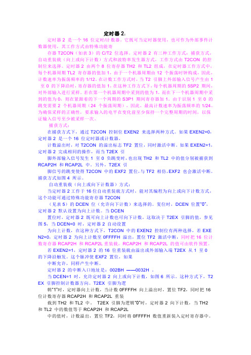
·定时器2:定时器2 是一个16 位定时/计数器。
它既可当定时器使用,也可作为外部事件计数器使用,其工作方式由特殊功能寄存器T2CON(如表3)的C/T2 位选择。
定时器2 有三种工作方式:捕获方式,自动重装载(向上或向下计数)方式和波特率发生器方式,工作方式由T2CON 的控制位来选择。
定时器2 由两个8 位寄存器TH2 和TL2 组成,在定时器工作方式中,每个机器周期TL2 寄存器的值加1,由于一个机器周期由12 个振荡时钟构成,因此,计数速率为振荡频率的1/12。
在计数工作方式时,当T2 引脚上外部输入信号产生由1至0 的下降沿时,寄存器的值加1,在这种工作方式下,每个机器周期的5SP2 期间,对外部输入进行采样。
若在第一个机器周期中采到的值为1,而在下一个机器周期中采到的值为0,则在紧跟着的下一个周期的S3P1 期间寄存器加1。
由于识别1 至0 的跳变需要2 个机器周期(24 个振荡周期),因此,最高计数速率为振荡频率的1/24。
为确保采样的正确性,要求输入的电平在变化前至少保持一个完整周期的时间,以保证输入信号至少被采样一次。
·捕获方式:在捕获方式下,通过T2CON 控制位EXEN2 来选择两种方式。
如果EXEN2=0,定时器2 是一个16 位定时器或计数器,计数溢出时,对T2CON 的溢出标志TF2 置位,同时激活中断。
如果EXEN2=1,定时器2 完成相同的操作,而当T2EX 引脚外部输入信号发生1 至0 负跳变时,也出现TH2 和TL2 中的值分别被捕获到RCAP2H 和RCAP2L 中。
另外,T2EX 引脚信号的跳变使得T2CON 中的EXF2 置位,与TF2 相仿,EXF2 也会激活中断。
捕获方式如图4 所示。
·自动重装载(向上或向下计数器)方式:当定时器2工作于16位自动重装载方式时,能对其编程为向上或向下计数方式,这个功能可通过特殊功能寄存器T2CON(见表5)的DCEN 位(允许向下计数)来选择的。
STC89C52单片机的一些程序,包括串口通信,定时中断

针对STC89C52RC单片机的一些程序基本串口通信程序:#include<reg52.h>#define uint unsigned int#define uchar unsigned char#define SEND 0#define RECEIVE 1uchar flag_Serial = SEND;uchar Rx_Buf;sbit SMG = P1^7;//0 1 2 3 4 5 6 7 8 9 a b c d e fuchar code Show[16]={0x03,0x9f,0x25,0x0d,0x99,0x49,0x41,0x1f,0x01,0x19,0x11,0xc1,0x63,0x85,0x61,0x71};void Serial_Init();void Serial_send();void Display();void Delay_1ms(uchar z);/****************************************************/ //main function///****************************************************/ void main(){Serial_Init();while(1){switch(flag_Serial){case SEND:flag_Serial = RECEIVE;Serial_send();break;case RECEIVE:Display();break;}}}/****************************************************/ //serial initial///****************************************************/ void Serial_Init(){TMOD = 0X20; //work in mode 2PCON = 0X00;SCON = 0X50;TH1 = 0XFD; //BRUD 9600TL1 = 0XFD;TR1 = 1; //open interrupt 1ES = 1; //open the serialEA = 1; //open the key interruptflag_Serial = SEND;SMG = 0;}/****************************************************/ //serial interrupt function///****************************************************/ void Serial() interrupt 4 using 2{EA = 0;if(RI!=0&&flag_Serial==RECEIVE){RI = 0;Rx_Buf = SBUF;flag_Serial = SEND;}EA = 1;}/****************************************************/ //mcu send data to serial///****************************************************/ void Serial_send(){SBUF = Rx_Buf;while(TI==0);TI=0;}/****************************************************/ //display the data by SMG///****************************************************/ void Display(){P2 = Show[Rx_Buf];Delay_1ms(3);}/****************************************************/ //delay for z*1ms///****************************************************/ void Delay_1ms(uchar z){uchar i,j;for(i=z;i>0;i--)for(j=110;j>0;j--);}串口通信,按键加减#include<reg52.h>#define uint unsigned int#define uchar unsigned char#define SEND 0#define RECEIVE 1sbit KEY1 = P1^4;sbit KEY2 = P1^5;sbit LED1 = P1^0;sbit LED2 = P1^1;sbit SMG = P1^7;uchar flag_Serial = SEND;uchar Rx_Buf;uchar Smg_Buf;//0 1 2 3 4 5 6 7 8 9 a b c d e fuchar code Show[16]={0x03,0x9f,0x25,0x0d,0x99,0x49,0x41,0x1f,0x01,0x19,0x11,0xc1,0x63,0x85,0x61,0x71};void Serial_Init();void Serial_send();void Display();void Delay_1ms(uchar z);void Scan();/****************************************************/ //main function///****************************************************/ void main(){Serial_Init();while(1){switch(flag_Serial){case SEND:flag_Serial = RECEIVE;Serial_send();break;case RECEIVE:Display();break;}Scan();}}/****************************************************/ //serial initial///****************************************************/ void Serial_Init(){TMOD = 0X20; //work in mode 2PCON = 0X00;SCON = 0X50;TH1 = 0XFD; //BRUD 9600TL1 = 0XFD;TR1 = 1; //open interrupt 1ES = 1; //open the serialEA = 1; //open the key interruptflag_Serial = SEND;SMG = 0;}/****************************************************/ //serial interrupt function///****************************************************/ void Serial() interrupt 4 using 2{EA = 0;if(RI!=0&&flag_Serial==RECEIVE){RI = 0;Rx_Buf = SBUF;flag_Serial = SEND;}EA = 1;}/****************************************************/ //mcu send data to serial///****************************************************/ void Serial_send(){SBUF = Rx_Buf;while(TI==0);TI=0;}/****************************************************/ //display the data by SMG///****************************************************/ void Display(){P2 = Show[Rx_Buf];Delay_1ms(3);}/****************************************************/ //delay for z*1ms/****************************************************/ void Delay_1ms(uchar z){uchar i,j;for(i=z;i>0;i--)for(j=110;j>0;j--);}/****************************************************/ //scan the keys///****************************************************/ void Scan(){if(KEY1==0){Delay_1ms(10);if(KEY1==0){LED1 = ~LED1;Rx_Buf++;if(Rx_Buf==16)Rx_Buf = 0;Display();while(KEY1==0);}}if(KEY2==0){Delay_1ms(10);if(KEY2==0){LED2 = ~LED2;if(Rx_Buf==0)Rx_Buf = 15;elseRx_Buf--;Display();while(KEY2==0);}}}串口通信,按键加减提示音,(利用定时中断)快速加减提示音#include<reg52.h>#define uint unsigned int#define uchar unsigned char#define SEND 0#define RECEIVE 1#define NORMAL 0#define INCREASE 1#define DECREASE 2sbit KEY1 = P1^4;sbit KEY2 = P1^5;sbit LED1 = P1^0;sbit LED2 = P1^1;sbit SMG = P1^7;sbit SPEAKER = P1^6;uchar flag_Serial = SEND;uchar Rx_Buf;uchar count_2s;uchar flag_KS;//0 1 2 3 4 5 6 7 8 9 a b c d e fuchar code Show[16]={0x03,0x9f,0x25,0x0d,0x99,0x49,0x41,0x1f,0x01,0x19,0x11,0xc1,0x63,0x85,0x61,0x71};void Serial_Init();void Serial_send();void Display();void Delay_1ms(uchar z);void Scan();/****************************************************/ //main function///****************************************************/ void main(){Serial_Init();while(1){switch(flag_Serial){case SEND:flag_Serial = RECEIVE;Serial_send();break;case RECEIVE:Display();break;}Scan();}}/****************************************************/ //serial initial///****************************************************/ void Serial_Init(){TMOD = 0X21; //work in mode 2PCON = 0X00;SCON = 0X50;TH1 = 0XFD; //BRUD 9600TL1 = 0XFD;TR1 = 1; //open interrupt 1ES = 1; //open the serialTH0 = (65536-50000)/256;TL0 = (65536-50000)%256;ET0 = 1;TR0 = 0;EA = 1; //open the key interruptflag_Serial = SEND;SMG = 0;}/****************************************************/ //serial interrupt function///****************************************************/ void Serial() interrupt 4{EA = 0;if(RI!=0&&flag_Serial==RECEIVE){RI = 0;Rx_Buf = SBUF;flag_Serial = SEND;}EA = 1;}/****************************************************/ //interrupt zero function///****************************************************/ void Timer0() interrupt 1{TH0 = (65536-50000)/256;TL0 = (65536-50000)%256;count_2s++;if(count_2s==40) //50ms*40=2s{count_2s=0;if(KEY1==0)flag_KS = INCREASE;elseflag_KS = DECREASE;}}/****************************************************/ //mcu send data to serial///****************************************************/ void Serial_send(){SBUF = Rx_Buf;while(TI==0);TI=0;}/****************************************************/ //display the data by SMG///****************************************************/void Display(){P2 = Show[Rx_Buf];}/****************************************************/ //delay for z*1ms///****************************************************/ void Delay_1ms(uchar z){uchar i,j;for(i=z;i>0;i--)for(j=110;j>0;j--);}/****************************************************/ //scan the keys///****************************************************/ void Scan(){if(KEY1==0){Delay_1ms(10);if(KEY1==0){LED1 = 0;SPEAKER = 0;Delay_1ms(250);SPEAKER = 1;Delay_1ms(250);LED1 = 1;flag_Serial = SEND;Rx_Buf++;if(Rx_Buf==16)Rx_Buf = 0;Display();while(KEY1==0){TR0 = 1;ES = 0;if(flag_KS==INCREASE && count_2s==4){count_2s=0;Rx_Buf++;if(Rx_Buf==16)Rx_Buf = 0;SPEAKER = 0 ;LED1 = 0 ;Delay_1ms(200);SPEAKER = 1 ;LED1 = 1 ;Delay_1ms(200);Display();}}flag_KS = NORMAL;ES = 1;TR0 = 0;}}if(KEY2==0){Delay_1ms(10);if(KEY2==0){LED2 = 0;SPEAKER = 0;Delay_1ms(125);SPEAKER = 1;Delay_1ms(250);LED2 = 1;flag_Serial = SEND;if(Rx_Buf==0)Rx_Buf = 15;elseRx_Buf--;Display();while(KEY2==0){TR0 = 1;ES = 0;if(flag_KS==DECREASE && count_2s==4){count_2s=0;if(Rx_Buf==0)Rx_Buf = 15;elseRx_Buf--;SPEAKER = 0 ;LED2 = 0 ;Delay_1ms(200);SPEAKER = 1 ;LED2 = 1 ;Delay_1ms(200);Display();}}flag_KS = NORMAL;ES = 1;TR0 = 0;}}}。
89C52串口通信
89C52串口通信
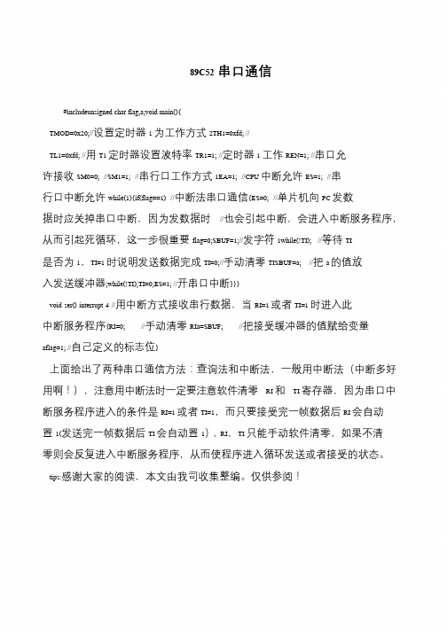
#includeunsigned char flag,a;void main(){
TMOD=0x20;//设置定时器1 为工作方式2TH1=0xfd; //
TL1=0xfd; //用T1 定时器设置波特率TR1=1; //定时器1 工作REN=1; //串口允许接收SM0=0; //SM1=1; //串行口工作方式1EA=1; //CPU 中断允许ES=1; //串行口中断允许while(1){if(flag==1) //中断法串口通信{ES=0; //单片机向PC 发数据时应关掉串口中断,因为发数据时//也会引起中断,会进入中断服务程序,从而引起死循环,这一步很重要flag=0;SBUF=1;//发字符1while(!TI); //等待TI 是否为1,TI=1 时说明发送数据完成TI=0;//手动清零TISBUF=a; //把a 的值放入发送缓冲器;while(!TI);TI=0;ES=1; //开串口中断}}}
void ser() interrupt 4 //用中断方式接收串行数据,当RI=1 或者TI=1 时进入此中断服务程序{RI=0; //手动清零RIa=SBUF; //把接受缓冲器的值赋给变量aflag=1; //自己定义的标志位}
上面给出了两种串口通信方法:查询法和中断法,一般用中断法(中断多好
用啊!),注意用中断法时一定要注意软件清零RI 和TI 寄存器,因为串口中断服务程序进入的条件是RI=1 或者TI=1,而只要接受完一帧数据后RI 会自动置1(发送完一帧数据后TI 会自动置1),RI,TI 只能手动软件清零,如果不清
零则会反复进入中断服务程序,从而使程序进入循环发送或者接受的状态。
tips:感谢大家的阅读,本文由我司收集整编。
仅供参阅!。
单片机AT89S52串行接口

数据转换为串行数据或将串行数据转换为并行数据。
串行接口在远程控制中的应用
远程控制
单片机AT89S52的串行接口可以用于实现远程控制功能,如通过 串行通信实现对设备的开关控制、参数设置等操作。
指令发送
控制中心通过串行接口向单片机发送控制指令,单片机接收到指令 后执行相应的操作。
状态反馈
单片机可以将设备的状态信息通过串行接口发送回控制中心,以便 控制中心了解设备的运行状态。
串行通信的优缺点
优点
线路简单,使用方便,成本低,适用 于远距离通信。
缺点
需要同步时钟信号,传输速度相对较 慢。
03
单片机AT89S52的串行接口
AT89S52的串行接口概述
01
02
03
串行通信接口
AT89S52单片机内置一个 全双工的串行通信接口, 支持异步和同步通信模式。
通信协议
该接口遵循RS-232标准, 支持数据传输速率为 2400bit/s、4800bit/s、 9600bit/s等。
04
串行接口的应用实例
串行接口在数据传输中的应用
数据传输
01
单片机AT89S52的串行接口可以用于数据的串行传输,如将数
据从单片机发送到其他设备或从其他设备接收数据。
通信协议
02
为了实现数据的正确传输,需要制定相应的通信协议,包括数
据的格式、波特率、校验方式等。
数据转换
03
在数据传输过程中,可能需要进行数据格式的转换,如将并行
05
总结与展望
单片机AT89S52串行接口的优势与局限性
高效的数据传输
AT89S52单片机具有高速的串行接口,可以实现快速的数据传输,满足实时性 要求高的应用场景。
STC89C52定时器3串口通信
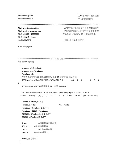
#include<reg52.h> //52系列单片机头文件#include<intrins.h> // 使用到空指令/*****************************************************************************/ #define uint unsigned int //用简写符号表示无符号整型数据类型#define uchar unsigned char //简写符号表示无符号字符型数据类型#define FOSC 12000000 //晶振大小值设定,便于计算波特率#define BAUD 9600sbit PWM=P1^1; //控制信号输出口定义uchar a,b,y,i,j,s[4];/*******************************串口初始化程序********************************/ void InitUART(void){unsigned int iTmpBaud;unsigned long lTmpBaud;iTmpBaud = 0;//首先选定定时器2作为波特率发生器,16位定时器,自动装载SCON = 0x50; //SM0 SM1 SM2 REN TB8 RB8 TI RI //0 1 0 1 0 0 0 0PCON = 0x00; //PCON的地址是87H,这里SMOD =0T2CON = 0x30;//TF2 EXF2 RCLK TCLK EXEN2 TR2 C(/T2) CP(/RL2) //0 0 1 1 0 0 0 0/* T2MOD = 0x00; // / / / / / / T2OE DCEN //0 0 0 0 0 0 0 0*/lTmpBaud = FOSC/BAUD;lTmpBaud /= 32; //12T-modeiTmpBaud = lTmpBaud & 0xFFFF;iTmpBaud = 65536 - iTmpBaud;RCAP2H = (iTmpBaud>>8) & 0x0FF;RCAP2L = iTmpBaud & 0x0FF;RI = 0; //清除接收中断标志REN = 1; //允许串行接收ES = 1; //允许串行中断TR2 = 1; //启动定时器1EA=1;//开总中断}//************************************通过串口将接收到数据发送给PC端**************************************void R_S_Byte(uchar R_Byte){SBUF = R_Byte;while( TI == 0 ); //查询法TI = 0;}//*********************************串口收到数据****************************************void UARTRead(void) interrupt 4 //接收上位机发送的控制指令{if(RI) //判断接收标志{s[i]=SBUF; //接收到的数据放入数组a}RI=0;i++;if(i==4){i=0;for(j=0;j<4;j++){R_S_Byte(s[j]);}}}//*********************************主程序***************************************void main(void){InitUART();while(1){}}。
第六章 AT89s52单片机并行IO口new
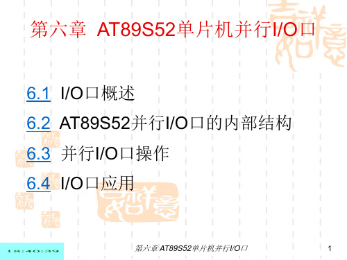
第六章 AT89S52单片机并行I/O口
23
(1)
3. P2口
位
结
构
和
工
作
原
理
多路开关的输入:一个是口输出锁存器的输出端Q; 一个是地址寄存器(PC或DPTR)的高位输出端。
第六章 AT89S52单片机并行I/O口
2
6.1.1 I/O接口的功能
1.地址译码 有译码器对地址进行译码,指定外设的端口,以便CPU 对寻址的外设进行读/写操作。
2.数据缓冲和锁存 (1)各输入装置的数据线都不能直接挂到CPU的数据 总线上,必须经输入缓冲器接到数据总线上。
(2)由于CPU和输出设备的处理速度有差别,必须增 加输出锁存器。
❖ 若第二输出功能为1时,与非门的输出为0,Q0截止, 从而使A点也为高电平。
第六章 AT89S52单片机并行I/O口
31
(3)P3口第二功能
第二输入功能:
▪ P3.0 —— RXD,串行输入口。
▪ P3.2 —— INT 0,外部中断0的请求。 ▪ P3.3 —— INT1,外部中断1的请求。 ▪ P3.4 ——T0,定时器/计数器0外部计数脉冲输入。
第六章 AT89S52单片机并行I/O口
26
(4) P2口使用中注意的问题
⑴ 由于P2口的输出锁存功能,在取指周期内或外 部数据存储器读、写选通期间,输出的高8位地 址是锁存的,故无需外加地址锁存器。
⑵ 如果外接有程序存储器,由于访问片外程序存储 器的连续不断的取指操作,P2口需要不断送出高 位地址,这时P2口的全部口线均不宜再作I/O口 使用。
AT89S52超简单的并口ISP下载线之DIY亲测成功

AT89S52单片机学习经验2号文件——AT89S52超简单的并口ISP下载线之DIYAT89S52单片机学习经验2号文件——AT89S52超简单的并口ISP下载线之DIY 经过五天的奋斗,我终于找到了一种对初学者来说超简单的并口ISP下载线制作方法。
(资源都来自网络,百度、Google 真是好东西啊!)制作S51的ISP下载线,网络上有一堆资料,但到底哪个对自己适合呢?这是个大问题,对我这个初学者就犯了个很大的错误——一上来就想整难的(制作AT89S52的串口ISP下载线,这浪费我三天的时间啊)。
现在市面上买的ISP下载线一般都是并口或USB口的,串口的很少。
因为串口制作比并口难,下载速度较慢,网络上非常成熟的DIY方法很少,极易出问题。
而制作USB口的ISP下载线,目前来说就非常专业了,制作这个对初学者来比登天还难呀,网上资料极少!而并口线下载速度快,制作简单,资料很全。
废话不多说了,入正题。
我是按照网络上的资料,自己整理做的一根并口下载线(就一个针头并口,六根线,一个接插件)。
上图我做这根下载线实际就花了30多分钟,调了半个小时。
当然之前,我还按照网友txz01的方法(方案见/txz01/blog/item/11c1c85089cf1b608435246e.html)用74HC373做了一个并口下载线,但用软件Easy 51Pro v2.0宇宙版调试总读不出正确的特征字,而我用软件ISPtest测试并口是正常的,最小系统也是正常的(尽管当时只知道晶振正常,但是后来下载线做好后,最小系统可以用下载线来正确地烧写程序——哈哈,事后诸葛亮啊!以后,我会注意拿事实说话。
PS:想了想事后拿事实验证也是可以的)。
我估计是74HC373处有问题(以后有时间,我再测试一下看看)。
按上图,做好下载线后,就到了这关键的一步,软件调试。
我是在软件IsPlay v1.5.0.1上调试成功的。
(注:我在Easy 51Pro v2.0宇宙版和PonyProg2000软件上也测试过,发现调试不成功。
at89c52单片机引脚说明
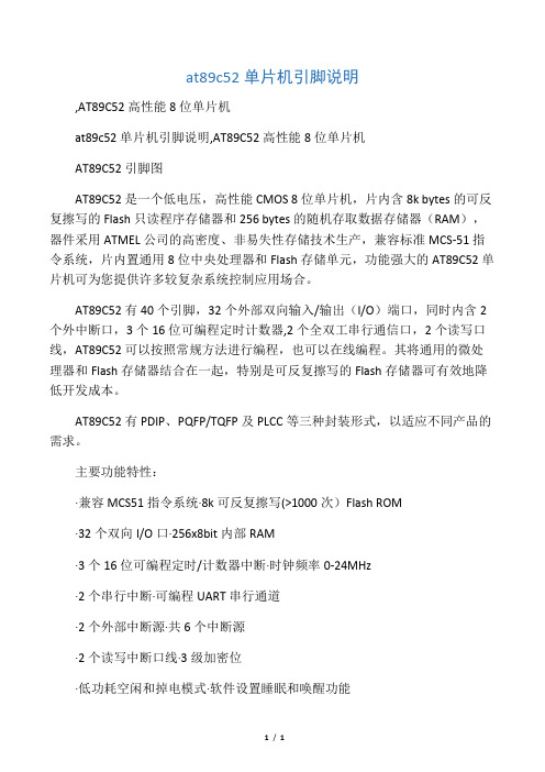
at89c52单片机引脚说明
,AT89C52高性能8位单片机
at89c52单片机引脚说明,AT89C52高性能8位单片机
AT89C52引脚图
AT89C52是一个低电压,高性能CMOS 8位单片机,片内含8k bytes的可反复擦写的Flash只读程序存储器和256 bytes的随机存取数据存储器(RAM),器件采用ATMEL公司的高密度、非易失性存储技术生产,兼容标准MCS-51指令系统,片内置通用8位中央处理器和Flash存储单元,功能强大的AT89C52单片机可为您提供许多较复杂系统控制应用场合。
AT89C52有40个引脚,32个外部双向输入/输出(I/O)端口,同时内含2个外中断口,3个16位可编程定时计数器,2个全双工串行通信口,2个读写口线,AT89C52可以按照常规方法进行编程,也可以在线编程。
其将通用的微处理器和Flash存储器结合在一起,特别是可反复擦写的Flash存储器可有效地降低开发成本。
AT89C52有PDIP、PQFP/TQFP及PLCC等三种封装形式,以适应不同产品的需求。
主要功能特性:
·兼容MCS51指令系统·8k可反复擦写(>1000次)Flash ROM
·32个双向I/O口·256x8bit内部RAM
·3个16位可编程定时/计数器中断·时钟频率0-24MHz
·2个串行中断·可编程UART串行通道
·2个外部中断源·共6个中断源
·2个读写中断口线·3级加密位
·低功耗空闲和掉电模式·软件设置睡眠和唤醒功能
1/ 1。
AT89S52串行通信

AT89S52串行通信学习目标:¾了解串行通信的基本知识¾掌握串行口的工作方式¾掌握波特率的设计¾掌握串行口工作方式的应用¾掌握程序调试的基本方法和技巧。
技能目标:¾会对串行口进行初始化。
¾会计算串行口通信波特率。
¾能够实现单片机与单片机之间、单片机和PC机之间的通信。
项目一单片机点对点通信第一部分项目要求利用AT89S52实现单片机点对点通信。
要求将存放在甲机的数据存储器20H—27H单元中数据,首先在甲机上显示,然后发送到PC机,进而再发送到乙机,以实现单片机与PC机和单片机与单片机之间的通信。
第二部分 相关知识一、 串行通信基本知识(一) 串行通信基本概念串行通信的特点是:数据是按位的顺序进行传送,最少只需一根传输线即可完成,成本低但速度慢。
计算机与外界的数据传送大多数是串行的,其传送的距离可以从几米到几千公里。
并行通信的特点是:各数据位同时传送,传送速度快、效率高。
但并行数据传送有多少数据位,就需多少根数据线,因此传送成本高。
串行数据通信共有以下几种数据通路形式。
1.单工(Simplex)形式单工形式的数据传送是单向的。
通信双方中一方固定为发送端,另一方则固定为接1收端。
单工形式的串行通信,只需要一条数据线。
如图5.1(a)所示。
例如计算机与打印机之间的串行通信就是单工形式,因为只能是计算机向打印机传送数据,而不可能有相反方向的数据传送。
2.半双工(Half-duplex)形式半双工形式的数据传送也是双向的。
但任何时刻只能由其中的一方发送数据,另一方接收数据。
因此半双工形式既可以使用一条数据线,也可以使用两条数据线。
如图5.1(b)所示。
3.全双工(Full-duplex)形式全双工形式的数据传送是双向的,且可以同时发送和接收数据,因此全双工形式的串行通信需要两条数据线。
如图5.1 (c)所示。
图5.1 串行通信的数据通路形式(二) 串行通信基本通信方式按照串行数据的同步方式,串行通信可分为异步通信方式和同步通信方式。
单片机AT89C52简要说明
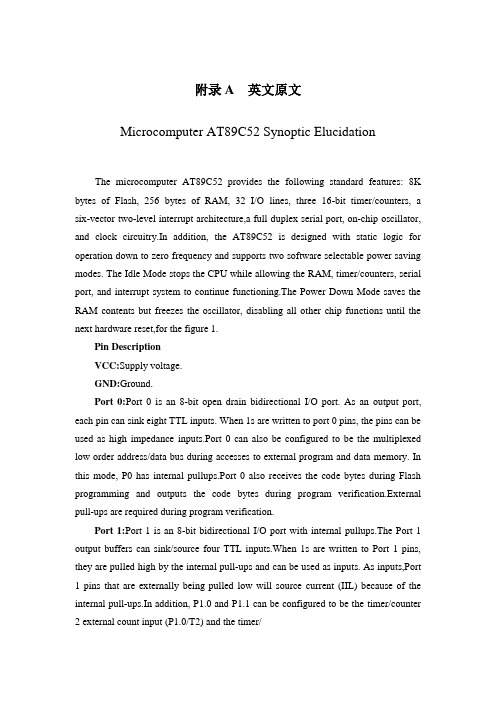
附录A 英文原文Microcomputer AT89C52 Synoptic ElucidationThe microcomputer AT89C52 provides the following standard features: 8K bytes of Flash, 256 bytes of RAM, 32 I/O lines, three 16-bit timer/counters, a six-vector two-level interrupt architecture,a full duplex serial port, on-chip oscillator, and clock circuitry.In addition, the AT89C52 is designed with static logic for operation down to zero frequency and supports two software selectable power saving modes. The Idle Mode stops the CPU while allowing the RAM, timer/counters, serial port, and interrupt system to continue functioning.The Power Down Mode saves the RAM contents but freezes the oscillator, disabling all other chip functions until the next hardware reset,for the figure 1.Pin DescriptionVCC:Supply voltage.GND:Ground.Port 0:Port 0 is an 8-bit open drain bidirectional I/O port. As an output port, each pin can sink eight TTL inputs. When 1s are written to port 0 pins, the pins can be used as high impedance inputs.Port 0 can also be configured to be the multiplexed low order address/data bus during accesses to external program and data memory. In this mode, P0 has internal pullups.Port 0 also receives the code bytes during Flash programming and outputs the code bytes during program verification.External pull-ups are required during program verification.Port 1:Port 1 is an 8-bit bidirectional I/O port with internal pullups.The Port 1 output buffers can sink/source four TTL inputs.When 1s are written to Port 1 pins, they are pulled high by the internal pull-ups and can be used as inputs. As inputs,Port 1 pins that are externally being pulled low will source current (IIL) because of the internal pull-ups.In addition, P1.0 and P1.1 can be configured to be the timer/counter 2 external count input (P1.0/T2) and the timer/counter 2 trigger input (P1.1/T2EX), respectively, as shown in the following table.Port 1 also receives the low-order address bytes during Flash programming and verification.Port 2:Port 2 is an 8-bit bidirectional I/O port with internal pullups.The Port 2 output buffers can sink/source four TTL inputs.When 1s are written to Port 2 pins, they are pulled high by the internal pull-ups and can be used as inputs. As inputs, Port 2 pins that are externally being pulled low will source current (IIL) because of the internal pull-ups. Port 2 emits the high order address byte during fetches from external program memory and during accesses to external data memory that use 16-bit addresses (MOVX @DPTR). In this application, Port 2 uses strong internal pull-ups when emitting 1s. During accesses to external data memory that use 8-bit addresses (MOVX @ RI), Port 2 emits the contents of the P2 Special Function Register.Port 2 also receives the high-order address bits and some control signals during Flash programming and verification.Port 3:Port 3 is an 8-bit bidirectional I/O port with internal pullups.The Port 3 output buffers can sink/source four TTL inputs.When 1s are written to Port 3 pins, they are pulled high by the internal pull-ups and can be used as inputs. As inputs,Port 3 pins that are externally being pulled low will source current (IIL) because of the pullups.Port 3 also serves the functions of various special features of the AT89C51, as shown in the following table.Port 3 also receives some control signals for Flash programming and verification.RST:Reset input. A high on this pin for two machine cycles while the oscillator is running resets the device.ALE/PROG:Address Latch Enable is an output pulse for latching the low byte of the address during accesses to external memory.This pin is also the program pulse input (PROG) during Flash programming.In normal operation, ALE is emitted at a constant rate of 1/6the oscillator frequency and may be used for external timing or clocking purposes. Note, however, that one ALE pulse is skipped during each access to external data memory.If desired, ALE operation can be disabled by setting bit 0 of SFR location 8EH. With the bit set, ALE is active only during a MOVX or MOVC instruction. Other- wise, the pin is weakly pulled high. Setting the ALE-disable bit hasno effect if the microcontroller is in external execution mode.PSEN:Program Store Enable is the read strobe to external program memory.When the AT89C52 is executing code from external program memory, PSEN is activated twice each machine cycle, except that two PSEN activations are skipped during each access to external data memory.EA/VPP:External Access Enable. EA must be strapped to GND in order to enable the图A.1 AT89C52方框图device to fetch code from external program memory locations starting at 0000H up to FFFFH.Note, however, that if lock bit 1 is programmed, EA will be internally latched on reset.EA should be strapped to VCC for internal program executions.This pin also receives the12-volt programming enable voltage(VPP) during Flash programming when 12-volt programming is selected.XTAL1:Input to the inverting oscillator amplifier and input to the internal clock operating circuit.XTAL2:Output from the inverting oscillator amplifier.Special Function Registers:Not all of the addresses are occupied, and unoccupied addresses may not be implemented on the chip.Read accesses to these addresses will in general return random data, and write accesses will have an indeterminate er software should not write 1s to these unlisted locations, since they may be used in future products to invoke new features. In that case, the reset or inactive values of the new bits will always be 0.Timer 2 Registers: Control and status bits are contained in registers T2CON and T2MOD for Timer 2. The register pair (RCAP2H,RCAP2L) are the Capture/Reload registers for Timer 2 in 16-bit capture mode or 16-bit auto-reload mode.Interrupt Registers: The individual interrupt enable bits are in the IE register. Two priori- ties can be set for each of the six interrupt sources in the IP register.Data Memory:The AT89C52 implements 256 bytes of on-chip RAM. The upper 128 bytes occupy a parallel address space to the Special Function Registers. That means the upper 128 When an instruction accesses an internal location above address 7FH, the address mode used in the instruction specifies whether the CPU accesses the upper 128 bytes of RAM or the SFR space. Instructions that use direct addressing access SFR space. For example, the following direct addressing instruction accesses the SFR at location 0A0H (which is P2).Instructions that use indirect addressing access the upper 128 bytes of RAM. For example, the following indirect addressing instruction, where R0 contains 0A0H, accesses the data byte at address 0A0H, rather than P2 (whose address is 0A0H). Note that stack operations are examples of indirect addressing, so the upper 128 bytes of data RAM are available as stack space.Timer 0 and 1:Timer 0 and Timer 1 in the AT89C52 operate the same way as Timer 0 and Timer 1 in the AT89C51.Timer 2:Timer 2 is a 16-bit Timer/Counter that can operate as either a timer or an event counter. The type of operation is selected by bit C/T2 in the SFR T2CON.Timer 2 has three operating modes: capture, auto-reload(up or down counting), and baud rate generator. The modes are selected by bits in T2CON.Timer 2consists of two 8-bit registers, TH2 and TL2. In the Timer function, the TL2 register is incremented every machine cycle. Since a machine cycle consists of 12 oscillator periods, the count rate is 1/12 of the oscillator frequency. In the Counter function, the register is incremented in response to a 1-to-0 transition at its corresponding external input pin, T2. In this function, the external input is sampled during S5P2 of every machine cycle. When the samples show a high in one cycle and a low in the next cycle, the count is incremented. The new count value appears in the register during S3P1 of the cycle following the one in which the transition was detected. Since two machine cycles (24 oscillator periods) are required to recognize a 1-to-0 transition,the maxi- mum count rate is 1/24 of the oscillator frequency.To ensure that a given level is sampled at least once before it changes, the level should be held for at least one full machine cycle.Capture Mode:In the capture mode, two options are selected by bit EXEN2 in T2CON. If EXEN2 = 0, Timer 2 is a 16-bit timer or counter which upon overflow sets bit TF2 in T2CON.This bit can then be used to generate an interrupt. If EXEN2 = 1, Timer 2 performs the same operation, but a 1-to-0 transition at external input T2EX also causes the current value in TH2 and TL2 to be captured into RCAP2H and RCAP2L, respectively. In addition, the transition at T2EX causes bit EXF2 in T2CON to be set. The EXF2 bit, like TF2, can generate an interrupt.Auto-Reload (Up or Down Counter):Timer 2 can be programmed to count up or down when configured in its 16-bit auto-reload mode. This feature is invoked by the DCEN (Down Counter Enable) bit located in the SFR T2MOD (see Table 4). Upon reset, the DCEN bit is set to 0 so that timer 2 will default to count up. When DCEN is set, Timer 2 can count up or down, depending on the value of the T2EX pin. Timer 2 automatically count up when DCEN = 0. In this mode, two option s are selected by bit EXEN2 in T2CON. If EXEN2 = 0, Timer 2 counts up to 0FFFFH and then sets the TF2 bit upon overflow. The overflow also causes the timer registers to be reloaded with the 16-bit value in RCAP2H and RCAP2L. The values in Timer in Capture ModeRCAP2H and RCAP2L are preset by software.If EXEN2 = 1, a 16-bit reload can be triggered either by an overflow or by a 1-to-0 transition at external input T2EX. This transi- tion also sets the EXF2 bit. Both the TF2 and EXF2 bits cangenerate an interrupt if enabled.Setting the DCEN bit enables Timer 2 to count up or down,as shown in Figure 3. In this mode, the T2EX pin controls the direction of the count. A logic 1 at T2EX makes Timer 2 count up. The timer will overflow at 0FFFFH and set the TF2 bit. This overflow also causes the 16-bit value in RCAP2H and RCAP2L to be reloaded into the timer registers,TH2 and TL2, respect- tively.A logic 0 at T2EX makes Timer 2 count down. The timer underflows when TH2 and TL2 equal the values stored in RCAP2H and RCAP2L. The underflow sets the TF2 bit and causes 0FFFFH to be reloaded into the timer registers.The EXF2 bit toggles whenever Timer 2 overflows or underflows and can be used as a 17th bit of resolution. In this operating mode, EXF2 does not flag an inter- rupt.Baud Rate Generator:Timer 2 is selected as the baud rate generator by setting TCLK and/or RCLK in T2CON (Table 2). Note that the baud rates for transmit and receive can be different if Timer 2 is used for the receiver or trans- mitter and Timer 1 is used for the other function. Setting RCLK and/or TCLK puts Timer 2 into its baud rate generator mode, as shown in Figure 4.The baud rate generator mode is similar to the auto-reload mode, in that a rollover in TH2 causes the Timer 2 registers to be reloaded with the 16-bit value in registers RCAP2H and RCAP2L, which are preset by software.The baud rates in Modes 1 and 3 are determined by Timer2’s overflow rate according to the following (A.1)equation.Modes1 and 3 band rates=Timer 2 Overflow Rate16(A.1)The Timer can be configured for either timer or counter operation. In most applications, it is configured for timer operation (CP/T2 = 0). The timer operation is different for Timer 2 when it is used as a baud rate generator. Normally,as a timer, it increments every machine cycle (at 1/12 the oscillator frequency). As a baud rate generator, however, it increments every state time (at 1/2 the oscillator frequency).The baud rate formula is given below(A.2).modes 1 and 3 band Rate =Oscillator frequency32[65536-(RCAP2H,RCAP2L)](A.2)where (RCAP2H, RCAP2L) is the content of RCAP2H and RCAP2L taken as a 16-bit unsigned integer Timer 2 as a baud rate generator is showed.This figure is valid only if RCLK or TCLK = 1 in T2CON. Note that a rollover in TH2 does not set TF2 and will not generate an interrupt. Note too, that if EXEN2 is set, a 1-to-0 transition in T2EX will set EXF2 but will not cause a reload from (RCAP2H, RCAP2L) to (TH2, TL2). Thus when timer 2 is in use as a baud rate generator, T2EX can be used as an extra external interrupt. Note that when Timer 2 is running (TR2 = 1) as a timer in the baud rate generator mode, TH2 or TL2 should not be read from or written to. Under these conditions, the Timer is incremented every state time, and the results of a read or write may not be accurate. The RCAP2 registers may be read but should not be written to, because a write might overlap a reload and cause write and/or reload errors. The timer should be turned off (clear TR2) before accessing the Timer 2 or RCAP2 registers.附录B 中文翻译单片机AT89C52简要说明AT89C52提供以下标准功能:8k字节Flash闪速存储器,256字节内部RAM,32个I/O口线,3个16位定时/计数器,一个6向量两级中断结构,一个全双工串行通信口,片内振荡器及时钟电路。
单片机89C52RC串口读取am2320温湿程序
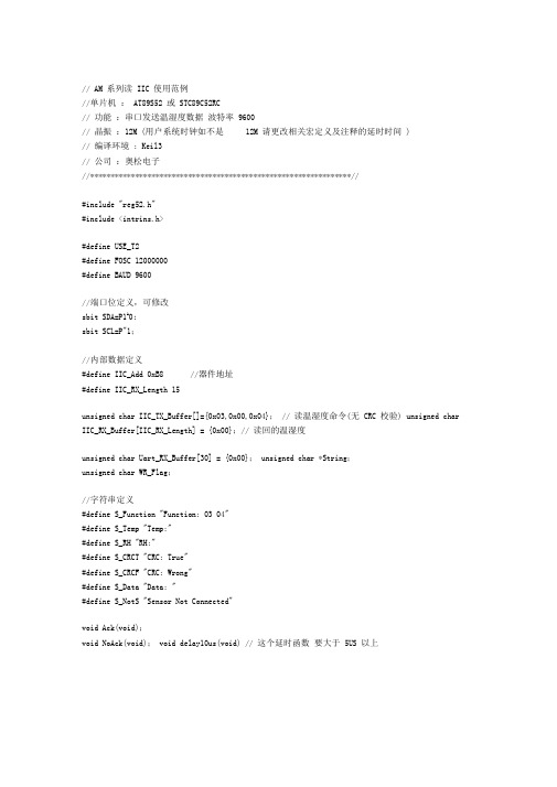
// AM 系列读IIC 使用范例//单片机:AT89S52 或STC89C52RC// 功能:串口发送温湿度数据波特率9600// 晶振:12M (用户系统时钟如不是12M 请更改相关宏定义及注释的延时时间)// 编译环境: Keil3// 公司:奥松电子//****************************************************************//#include "reg52.h"#include <intrins.h>#define USE_T2#define FOSC 12000000#define BAUD 9600//端口位定义,可修改sbit SDA=P1A0;sbit SCL=P"1;//内部数据定义#define IIC_Add 0xB8 //器件地址#define IIC_RX_Length 15unsigned char IIC_TX_Buffer[]={0x03,0x00,0x04}; // 读温湿度命令(无CRC 校验) unsigned char IIC_RX_Buffer[IIC_RX_Length] = {0x00};// 读回的温湿度unsigned char Uart_RX_Buffer[30] = {0x00}; unsigned char *String;unsigned char WR_Flag;//字符串定义#define S_Function "Function: 03 04"#define S_Temp "Temp:"#define S_RH "RH:"#define S_CRCT "CRC: True"#define S_CRCF "CRC: Wrong"#define S_Data "Data: "#define S_NotS "Sensor Not Connected"void Ack(void);void NoAck(void); void delay10us(void) // 这个延时函数要大于5US 以上_nop_(); _nop_(); _nop_();_nop_(); _nop_(); _nop_(); }void delay1ms(unsigned int t){unsigned int i;unsigned int j;for(j=t;j>0;j--) for(i=124;i>0;i--);}void InitUART(void) {unsigned int iTmpBaud;unsigned long lTmpBaud; iTmpBaud = 0;//首先选定定时器 2 作为波特率发生器 ,16位定时器 ,自动装载SCON = 0x50; //SM0 SM1 SM2 REN TB8 RB8 TI RI //0 1 0 1 0 00 0PCON = 0x00; //PCON 的地址是 87H, 这里 SMOD =0//TF2 EXF2 RCLK TCLK EXEN2 TR2 C(/T2) CP(/RL2) //0 0 1 1 0 0 0 // / / / / / / T2OE DCEN //0 0 0 0 0 0 0 0//fosc = 22.1184M,6T: 144, 设置波特率//(RCAP2H,RCAP2L) = 65536- fosc/(n*Baud) 。
将 AT89C52 用作多功能外围器件使用

将AT89C52用作多功能外围器件使用文章作者:过幼南文章出处:单片机及嵌入式系统应用摘要:介绍利用AT89C52单片机作为多功能可编程接口的方法。
该接口具有1个键盘/显示接口,2个16位定时/计数器和1个全双工异步串行通信口。
其模块化的设计,可以给用户使用带来许多方便。
关键词:多功能接口串行通信软件译码AT89C52(简称89C52)的广泛使用,使单片机的价格大大下降。
目前,89C52的市场零售价已经低于8255、8279、8253、8250等专用接口芯片中的任何一种;而89C52的功能实际上远远超过以上芯片。
因此,如把89C52作为接口芯片使用,在经济上是合算的。
在本人设计的系统中,将89C52设计为多功能可编程接口,其相关程序固化在片内的Flash ROM中。
该芯片(以下简称多功能接口)具有如下功能:①有1个专用的键盘/显示接口;②有1个全双工异步串行通信接口;③有2个16位定时/计数器。
这样,1个89C52芯片,承担了3个专用接口芯片的工作;不仅使成本大大下降,而且优化了硬件结构和软件设计,给用户带来许多方便。
1 硬件结构把89C52当作接口使用,接口自身必须尽可能地少占用硬件资源,与主系统之间的连接线也应尽可能少,这样才能少占主机引脚,把更多的资源留给系统。
本设计中,主机与多功能接口之间采用串行通信。
主机与多功能接口之间有四根连接线:CE、CLK、DAT、INTR。
CE用于作片选信号输入端。
此引脚为低电平时,主机能与多功能接口进行数据传送。
CLK为时钟输入端,当主机向多功能接口发送指令时,此引脚电平上升表示数据有效。
DAT为串行数据输入/输出端。
INTR为多功能接口输出端。
当多功能接口内的数据准备好时,由INTR向主机发低电平,通知主机,数据已准备就绪,可以进行读操作。
该信号可供主机查询,也可用作发向主机的中断请求信号。
89C52的P0、P1、P2口用作键盘/显示接口。
用程序扫描的方法进行键盘输入和显示输出。
学习情景五AT89S52串行通信- PowerPoint 演示文稿.

PCON不能位寻址。
SMOD—串行口波特率的倍增位
当SMOD=1时,串行口波特率加倍。
系统复位时,SMOD=0。
学习情景五
AT89S52串行通信
三、AT89S52串行口工作方式 (一)串行口波特率设计 1. 波特率 波特率的定义是每秒钟传送二进制数码的位数 (亦称比特数),单位是b/s。 假设数据传送速率是120字符/s,而每个字符 格式包含10个代码(1个起始位、1个终止位、 8个数据位)。这时,传送的波特率为 (10b/字符)×120字符/s = 1200 b/s 每一位代码的传送时间Td为波特率的倒数。
④T1IN、T2IN是2路TTL电平发送输入端,接80S52的 TxD发送端; ⑤T1OUT、T2OUT是2路转换后的发送RS-232C电平信 号输出端,接传输线;
⑥V+经电容接电源十5V;
⑦V-经电容接地。
学习情景五
AT89S52串行通信
PC机与AT89S52单片机串行通信电路 图中外接电解电容C1、C2、C3、C4用于电源电压变换, 提高抗干扰能力,它们可以取相同数值电容1.0 μF/16 V。电 容C5用于对+5 V电源的噪声干扰进行滤波,其值一般为0.1 μF
距离在15米左右,采用 RS-232标准接口。
如果是长距离传送,可采用RS-485标准。
学习情景五
AT89S52串行通信
(一)RS-232标准
RS-232C标准是美国EIA(电子工业联合会) 与BELL等公司一起开发的于1969年公布的通信协议。 1. RS-232C的电气特性 (1)数据线上的信号电平
学习情景五
AT89S52串行通信
接收前置REN=1和RI=0,当8位数据接收结束,RI被 置“1”,可通过指令MOV A,SBUF将数据读入。 下图采用一个串入并出移位寄存器,TXD连接串 行口输出移位寄存器164的时钟端,RXD连接164的 输入端,P1.0连接164的CLR选通端。
单片机_AT89S52串行接口
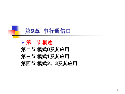
31
模式1原理示意图(发送部分)
发送过程
由写SBUF启动,在8位数据后加上一个停止位。 开始发送,但DATA无效,送出一个起始位 当零检测器全0,再作最后一次移位,并置TI
33
发送时序
34
零检测器变化过程
再做最后一次移位同时TI置1,发送1帧完成。
35
模式1原理示意图(接收部分)
接收过程
47
回忆PSW:程序状态字,存放指令执行后的有关状态
P: (PSW.0)奇偶标志位,用来标志累加器ACC中1的个数, 可以用在串行通信中作奇偶校验判断。当 P=1时 ,表明A中 1 的个数为奇数个,反之为偶数个。 ACC=0x0; /* P=0 */ ACC=0x80; /* P=1 */48分析:波特率
一律改成奇校验此时p1开始发送while等这1个字节发完才能发下1字节end循环结束endmain编程实现续52串口不断接收发来的字符串已知字符串长度为14字节若14字节均无错则使接在p10引脚上的绿色led闪烁3次后点亮若有错则使接在p11引脚上的红色led闪烁3次后点亮要求波特率为1200采用串口模式1最高位约定做奇校验位已知fosc110592mhz
45
例1
发送字符串 “Hello World!\n” 至串口,要求波特率为
1200,采用串口模式1,最高位约定做奇校验位,已知 Fosc=11.0592MHz。
46
分析:奇偶校验
由于传输的是 ASCII 字符( 0-7FH),只需要 7 位, 对于模式1有8个数据位,将最高位做奇校验位,保证形成 的8位中1的个数始终是奇数个;接收方收到每一个字节后 进行奇偶判断,若为奇则认为无误,若为偶则表示出错, 这种方法可以检测出奇数个误码。 例如,若要发送 0x00,加奇校验位后变成 0x80; 若 要发送0x01,加奇校验位后仍为0x01。接收方判断无错 后去掉最高位,还原需要的数据。
- 1、下载文档前请自行甄别文档内容的完整性,平台不提供额外的编辑、内容补充、找答案等附加服务。
- 2、"仅部分预览"的文档,不可在线预览部分如存在完整性等问题,可反馈申请退款(可完整预览的文档不适用该条件!)。
- 3、如文档侵犯您的权益,请联系客服反馈,我们会尽快为您处理(人工客服工作时间:9:00-18:30)。
if(RI == 1) //当硬件接收到一个数据时,RI会置位
{
LED_Buffer[i]=SBUF-48;//这里减去48是因为从电脑中发送过来的数据
是ASCII码。
RI = 0;
if(i==8)
{
i = 0;
}
i++;
}
}
void Com_Init(void)
{
TMOD = 0x20;
PCON = 0x00;
SCON = 0x50;
TH1 = 0xfd; //设置波特率9600
TL1 = 0xfd;
TR1 = 1; //启动定时器1
ES = 1; //开串口中断
EA = 1; //开总中断
}
void Main()
{
uchar i = 0;
Delay_1ms(100);
Com_Init();
while(1)
while(1)
{
SBUF = *p;
while(!TI) //如果发送完毕,硬件会置位TI
{
_nop_();
}
p++;
if(*p==‘‘)
{
Delay(200); //延时2秒钟再进行下次发送
TI = 0;
break; //在每个字符串的最后,会有一个’’
}
TI = 0; //TI清零
}
}
}
说明:
完成物理层的传输,另外一方即可根据电压判断不同的01,然后形成8位的
并行数据。
接受程序:
#include
#include
#define uchar unsigned char
#define uint unsigned int
uchar code table[10] ={0x3f,0x06,0x5b,0x4f,0x66,0x6d,0x7d,0x07,0x7f,0x6f};
串口的初始化中,需要设置TIME1,这个定时器的的溢出率在波特率中有
用,其中PCON电源控制器最高位SMOD与波特率有关系,然后就是设置
TIME1的初始值,开启定时器。
当发送1个数值后,就是8位,即1个字符,先赋值给SBUF,由SBUF
将并行的数据换成串行的数据在P3.1中根据01的不同会出现不同的电压即
{
TMOD = 0x20;//方式2,8位自动填充
PCON=1SCON=0x40;//SM0,SM1,SM2,REN,TB8,RB8,TI,RI设置为0x40,
不允许读,串口工作方式1,波特率可变为2smod*fosc/[32*12*(256-x)]
TH1 = 0xfd;
TL1 = 0xfd;//19200自填充
uchar LED_Buffer[8] = {0}; //从串口接收的数据
void Delay_1ms(uint i)//1ms延时
{
uchar x,j;
for(j=0;j
for(x=0;x}
void Com_Int(void) interrupt 4
{
staticuchari=0;//定义为静态变量,当重新进入这个子函数时i的值不会
AT89C52简单的串口操作
#include
#include
#define uchar unsigned char
#define uint unsigned int
void Delay(uint del)
{
uint i,j;
for(i=0; i
for(j=0; j;
}
void Com_Init(void)
{
P0 = table[LED_Buffer[i]];
P2 = i++;
Delay_1ms(1);
if(i == 8) i=0;
}
}
说明:
可以再串口RI或者TI置位后,设置中断函数,TI和RI由硬件。通过RI
置位可以读取接受到的数组。
然后做进一步的传输。
TR1 = 1;//启动定时器
}
void Main()
{
uchar i = 0;
ucharcodeBuffer[]=WelcomeToTheMCUWorld.dlmcu.taobao
QQ:85536436 ; //所要发送的数据
uቤተ መጻሕፍቲ ባይዱhar *p;
Com_Init();
while(1)
{
p = Buffer;
