JS14P的说明书
SPAJ 142CmanualCNa_v5
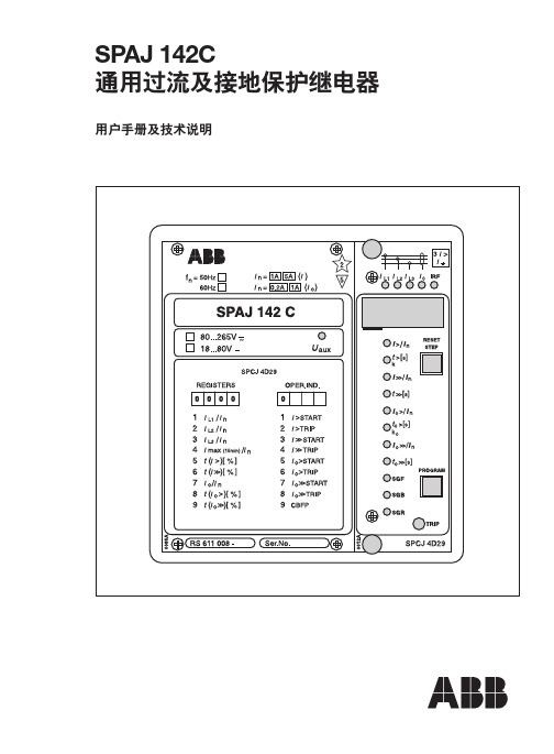
51BF
IRF
Serial I/O
图 1. SPAJ 142C 过流与接地保护继电器的保护功能
3
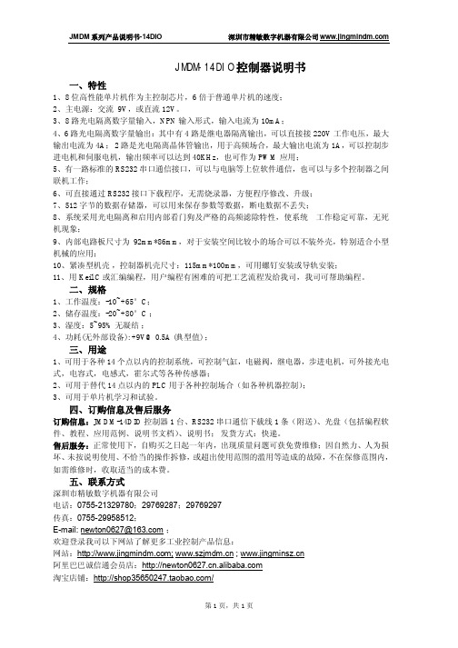
L1 L2 L3
0-
图 2. SPAJ 142C 通用过流及接地保护继电器的接线原理图
德力西 JS14P 系列时间继电器 说明书

本系列时间继电器,均采用中规模集成电路、 LED发光 二极管指示,数字拔码开关预置,具有设定方便,工作稳定 可靠,延时精度高,体积小等特点。
三、技术特征
3.1 额定绝缘电压Ui: AC380V 3.2 额定冲击耐受电压Uimp:AC2.5kV 3.3 额定控制电源电压Us:AC:380V、220V、127V、110V、 36V、24V、12V;DC:220V、127V、110V、36V、24V、12V; AC/DC24V~48V;AC/DC100V~240V。 3.4 使用类别下各个额定工作电压Ue/额定工作电流Ie: AC-15 Ue:AC380V,Ie:0.95A;Ue:AC240V,Ie:1.5A;
四、产品外形及安装尺寸
8-Φ4为板后 接线时的穿线孔
单位:(mm)
45.5max
97.5max
2-Φ 4.5
55±0.5 ≥90
84.5max 35.5±0.30
JS14P、JS14P-D外形尺寸图
52.5max
114max
பைடு நூலகம்10
装置式安装尺寸图
(或采用35mm标准导轨安装) 45+00.50
77+00.50
确属产品本身质量问题的产品,请与当地经销公司或 我公司联系。
七、运输与贮存
产品贮存和运输过程中不受到雨雪的侵袭,及挤压,在贮 存时应放置在空气流通,相对湿度(25℃±5℃)不超过90%。 温度下限为-25℃,温度上限为+55℃。
八、开箱及检查
打开外包装纸盒,检查包装盒内应有,使用说明书。
九、订货须知
-6-
额定控制电源电压U s:见3.3 延 时 时 间:见 表 安装形式:不标注表示装置式;M标 示面板式 延时型式规格代号:无标注为通电延时;
SP-140T电子氧化铅盾焊接机说明书

WIRE FEEDER WELDER SP-140T®Publication E7.62.1 (02/22)©Lincoln Global Inc. All Rights Reserved. All trademarks and registered trademarks are the property of their respective owners. Shown: K5261-1GENERAL OPTIONSWelding CartFull-featured cart is designed to store andtransport a welder, 80 cubic foot gas cylinder,welding cables and accessories. Includes anangled top shelf for easy access to weldercontrols, a lower tray for added storage space,a sturdy handle also used as a convenientcable wrap hanger. K2275-1Utility CartHeavy duty cart stores and transports welder,150 cubic foot shielding gas cylinder, weldingcables and accessories. Includes stableplatforms for welder and gas bottle platform,lower tray for added storage capacity andadjustable height handle. Order K520Small Canvas CoverProtect your welder when not in use. Madefrom attractive red canvas that is flameretardant, mildew resistant and waterrepellent. Includes a convenient side pocket tohold your welding torch or gun.Order K2377-1WIRE FEEDER OPTIONSMagnum® PRO 100SG Spool Gun (4 PIN)Designed to easily feed 4 in. (102 mm) diameter1 lb. (0.45 kg) spools of 0.030 in. (0.8 mm) or0.035 in. (0.9 mm) diameter SuperGlaze®aluminum MIG wire. Includes gun, adapterkit, 0.035 in. (0.9 mm) contact tips (qty.3), gas nozzle, and a 1 lb. (0.45 kg) spool ofSuperGlaze® 4043 0.035 in. (0.9 mm) MIG wire.Packaged in a convenient carrying case.Order K3269-1Welding Fume ExtractorsLincoln Electric offers a wide variety ofwelding fume extraction environmentalsystem solutions, ranging from portablesystems easily wheeled around the shop toshop-wide central systems servicing manydedicated welding stations.Request Publication E13.40 WHAT’S INCLUDEDMagnum® PRO 100L gun, 10 ft. (3.0 m)Gas NozzleGas DiffuserCable Liner035 in. (0.9 mm) Contact TipWork Cable and ClampAdjustable Gas Regulator and HoseSpindle Adapter0.025 - 0.030 in. (0.6 - 0.7 mm) and 0.035 in.(0.9 mm) Smooth Drive Roll for MIG & FCAWThe Lincoln Electric Company22801 St. Clair Avenue • Cleveland, OH • 44117-1199 • U.S.A.C USTOMER ASS ISTANC E POL ICYThe business of Lincoln Electric is manufacturing and selling high quality welding equipment, automated welding systems, consumables, and cutting equipment. Our challenge is to meet the needs of our customers, who are experts in their fields, and to exceed their expectations. On occasion, purchasers may ask Lincoln Electric for information or technical information about their use of our products. Our employees respond to inquiries to the best of their ability based on information and specifications provided to them by the customers and the knowledge they may have concerning the application. Our employees, however, are not in a position to verify the information provided or to evaluate the engineering requirements for the particular weldment, or to provide engineering advice in relation to a specific situation. Accordingly, Lincoln Electric does not warrant or guarantee or assume any liability with respect to such information or communications. Moreover, the provision of such information or technical information does not create, expand, or alter any warranty on our products. Any express or implied warranty that might arise from the information or technical information, including any implied warranty of merchantability or any warranty of fitness for any customers’ particular purpose or any other equivalent or similar warranty is specifically disclaimed.Lincoln Electric is a responsive manufacturer, but the definition of specifications, and the selection and use of specific products sold by Lincoln Electric is solely within the control of, and remains the sole responsibility of the customer. Many variables beyond the control of Lincoln Electric affect the results obtained in applying these types of fabrication methods and service requirements.Subject to Change – This information is accurate to the best of our knowledge at the time of printing. Please refer to for any updated information.All trademarks and registered trademarks are the property of their respective owners.For best welding results with Lincoln Electric ®equipment, always use Lincoln Electric consumables. Visit for more details.SP - Single PassMP - Multiple PassAluminum welding requires optional K4360-1 Magnum® PRO spool gun.(1)。
《电路与电子技术》课件.

FU
RT14圆筒形熔断器
熔断器底座
螺旋式熔断器
熔体额定电流的选择: 1.照明线路等没有冲击电流的负载 熔体额定电流≥被保护设备的额定电流 2. 一台电动机的熔体 熔体额定电流≥ 电动机的起动电流 2.5 如果电动机起动频繁,则为 电动机的起动电流 熔体额定电流≥ 1.6 ~ 2 3. 多台电动机合用的总熔体 熔丝额定电流 = (1.5 ~ 2.5)容量最大的电动机额定电流 +其余电动机额定电流之和
SB
KM
KM
控制电路
M 3~
2. 单向运行控制电路
Q
FU SBSTP
FR SBST KM
KM
工作过程:按 下SBST → KM 得电→电动机 起动→按下 SBSTP → KM断 电→电动机停 止。
KM
FR
M 3~
过 载 保 护
自锁
用接触器本 身的触点使其线 圈保持通电的环 节称自锁环节。
3. 多地控制电路
7.1.6 热继电器
用途:主要用于电动机的过载保护。
i
热元件
弹簧
i
双金属片
动断 触点 复位 按钮
扣板
热继电器原理图
热继电器的图 形和文字符号
FR
热元件
动断触点
7.1.7 中间继电器
用途:用来传递或转换信号,或同时控制多个 电路,也可以直接控制小容量电动机或其它电气执 行元件。
结构:与交流接触器基本相同,只是容量小些, 触点多些。 选用:中间继电器主要考虑电压等级和触点数 量。
KMR
7.2.3 时限控制
时限控制:按一定的时间间隔来接通或断开控 制电路。 1. 时间继电器 分类:电磁式、空气阻尼式、电子式等类型。
Crystic Gelcoat 14PA 高性能纤维塑料组成工具喷涂剂说明书

CRYSTIC GELCOAT 14PAHigh Performance Vinylester Brush Tooling Gelcoat IntroductionCrystic Gelcoat 14PA is a pre-accelerated brush gelcoat specially formulated from a urethane modified, vinyl ester base resin and is available in a restricted range of colours. The information contained in this leaflet also applies to pigmented versions.ApplicationsCrystic Gelcoat 14PA is designed for use in the manufacture of high quality, FRP composite tooling.Features and BenefitsCrystic Gelcoat 14PA is heat resistant with high impact strength and good resistance to chemical attack. It is extremely resilient and can be polished to a high gloss. With its unique combination of properties, Crystic Gelcoat 14PA can help to overcome the problems of surface defects often encountered in FRP composite tooling. It is particularly effective against a phenomenon which has come to be known as ‘water marking’. This manifests itself after first use of the mould as follows:•combinations of gloss and matt areas in patches on the mould surface•surface undulations caused by shrink-back, often following the line of brush marks• a permanent defect which returns after apparent rectification and removalCrystic Gelcoat 14PA also reduces general reinforcement print-through.FormulationCrystic Gelcoat 14PA should be allowed to attain workshop temperature (18º - 20ºC) before use. Stir well by hand, or with a low shear mixer to avoid aeration, and then allow to stand to regain thixotropy. The air drying properties of the base resin mean that a skin may form on the surface of the gelcoat if it is left uncovered. Once weighed out, therefore, it should be kept in covered containers until it is used. Crystic Gelcoat 14PA requires only the addition of catalyst to start the curing reaction. The recommended catalyst is Butanox M50 (or other equivalent catalyst) which should be added at 2% into the gelcoat (please consult our Technical Service Department for advice, if other catalysts are to be used). The catalyst should be thoroughly incorporated into the gelcoat, with a low shear mechanical stirrer where possible.Pot LifeTemperature Pot Life in Minutes15ºC 2920ºC 2225ºC 14The gelcoat, mould and workshop should all be at, or above, 15ºC before curing is carried out.ApplicationCrystic Gelcoat 14PA is a tooling gelcoat and the application should be controlled at 0.5-0.6mm wet film thickness. As a guide, approximately 500-750g/m² of gelcoat mixture (depending on pigment) will give the required thickness when evenly applied. This will also allow for any rubbing down which may be necessary during the life of the mould. Due to the air drying nature of its base resin, Crystic Gelcoat 14PA cures to an almost tack-free surface. This has no adverse affect on the adhesion of the backing laminate.AdditivesCrystic Gelcoat 14PA is supplied in a restricted range of colours. This eliminates the potential for mixing errors with small quantities of pigment paste. The addition of fillers or pigments can adversely affect the durability of the mould, in use.Recommended TestingIt is recommended that customers test all pigmented gelcoats before use under their own conditions of applicationto ensure the required surface finish is achieved.Typical PropertiesThe following tables give typical properties of Crystic Gelcoat 14PA when tested in accordance with appropriate SB, BS EN or BS EN ISO test methods.GelcoatLiquidPropertycloudyYellowish, AppearanceViscosity @ 25ºC thixotropicSpecific Gravity @ 25ºC 1.07Acid Value mgKOH/g 4.9Volatile Content % 47Stability in the dark @ 20ºC months 3Gel time @ 25ºC using 2%Catalyst M (Butanox M50) minutes 10curedPropertyFully*Gelcoat(unfilled casting)40Barcol Hardness (model GYZJ934-1)Water Absorption 24 hrs @ 23ºC mg 18Deflection Temperature underload† (1.80 MPa) ºC 100Elongation at Break % 3.5Tensile Strength MPa 78Tensile Modulus MPa 3000* Curing Schedule - 24 hrs @ 20ºC, 3 hrs @ 80ºC† Curing Schedule - 24 hrs @ 20ºC, 5 hrs @ 80ºC, 3 hrs @ 120ºCPost CuringFor optimum life, a mould constructed using Crystic Gelcoat 14PA should be fully cured before being put into use. This can be achieved by placing the mould in an oven at 40ºC for 30 hours. If this is not practical, the mould should be left in warm conditions (20ºC) for 2-3 weeks prior to use. Where a mould is likely to experience severe conditions (eg due to high exotherm temperatures within backing laminates), it should be post cured at an elevated temperature. Contact our Technical Service department for advice.Mould Release SystemWhen a new mould is manufactured, traces of residual monomer (styrene) remain within the tooling gelcoat. Although post curing at 80°C will reduce this to an insignificant level, exposing a new mould to this temperature is not always practical or desirable. The first release from a new mould is, therefore, likely to be the most difficult, particularly if a mould which is not post cured is subjected to elevated temperatures during its initial use. These temperatures could arise from the exotherm of the laminate contained within the mould, or from the mould itself being passed through a heated curing area during use. The following procedure was developed to combat release problems on new moulds manufactured and cured at workshop temperature (18°C - 20°C). It demonstrates an excellent release performance on new moulds and is equally effective on moulds of any age:1.Before first use, allow the mould to mature for a minimum of 7 days at 18°C or above.2.Clean the mould thoroughly with Frekote PMC.3.Apply 2 coats of Frekote FMS (mould sealer), allowing a minimum of 10 minutes between coats.4.Apply 4 coats of Frewax, allowing a minimum of 10 minutes between coats.5.Optional - apply 1 coat of a hard wax such as Mirrorglaze or Polywax. This will reduce any tendency tode-wet or pre-release when the mould is used.6.After the first release, use a masking tape test to check that the release agent remains on the mould surface.If so, apply 1 coat of Frewax or a hard wax. If not, repeat steps 2 to 4.7.Continue as 6 until the release performance becomes predictable and easy then re-apply 1 coat of releaseagent as and when required.StorageCrystic Gelcoat 14PA should be stored in its original container and out of direct sunlight. It is recommended that the storage temperature should be less than 20ºC where practical, but should not exceed 30ºC. Ideally, containers should be opened only immediately prior to use.PackagingCrystic Gelcoat 14PA is supplied in 25 kg and 225 kg containers.Health and SafetyPlease see separate Material Safety Data SheetJanuary 2010Version 2。
JMDM-14DIO 控制器说明书
JMDM系列产品说明书-14DIO 深圳市精敏数字机器有限公司JMDM-14DIO控制器说明书一、特性1、8位高性能单片机作为主控制芯片,6倍于普通单片机的速度;2、主电源:交流9V,或直流12V。
3、8路光电隔离数字量输入,NPN输入形式,输入电流为10mA;4、6路光电隔离数字量输出:其中有4路是继电器隔离输出,可以直接接220V工作电压,最大输出电流为4A; 2路是光电隔离晶体管输出,用于高频场合,最大输出电流为1A,可以控制步进电机和伺服电机,输出频率可以达到40KHz,也可作为PWM应用;5、有一路标准的RS232串口通信接口,可以与电脑等上位软件通信,也可以与多个控制器之间联机工作;6、可直接通过RS232接口下载程序,无需烧录器,方便程序修改、升级;7、512字节的数据存储器,可以用来保存参数等数据,断电数据不丢失;8、系统采用光电隔离和启用内部看门狗及严格的高频滤除特性,使系统工作稳定可靠,无死机现象;9、内部电路板尺寸为92mm*86mm,对于安装空间比较小的场合可以不装外壳,特别适合小型机械的应用;10、紧凑型机壳,控制器机壳尺寸:115mm*100mm,可用螺钉安装或导轨安装;11、用Keil C 或汇编编程,用户编程有困难的可把工艺流程发给我司,我司可帮助编程。
二、规格1、工作温度:-10~+65°C;2、储存温度:-20~+80°C ;3、湿度:5~95% 无凝结;4、功耗(无外部设备):+*******(典型值) ;三、用途1、可用于各种14个点以内的控制系统,可控制气缸,电磁阀,继电器,步进电机,可外接光电式,电容式,电感式,霍尔式等各种传感器;2、可用于替代14点以内的PLC用于各种控制场合(如各种机器控制);3、可用于单片机学习和试验。
四、订购信息及售后服务订购信息:JMDM-14DIO控制器1台、RS232串口通信下载线1条(附送)、光盘(包括编程软件、教程、应用范例、说明书文档)、说明书;发货方式:快递。
人民电器 QX4系列自动星—三角起动器 产品说明书
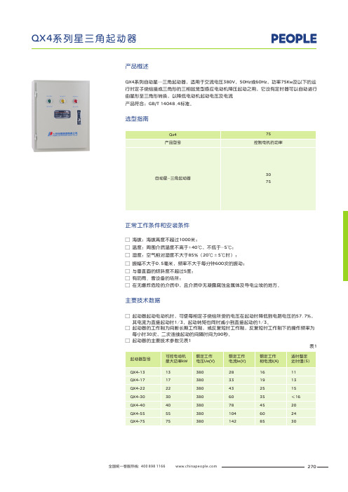
产品概述选型指南QX4系列自动星—三角起动器,适用于交流电压380V,50Hz或60Hz,功率75Kw及以下的运行时定子绕组接成三角形的三相鼠笼型感应电动机降压起动之用,它设有定时器可以自动进行由星形至三角形转换,以降低电动机起动电压及电流产品符合:GB/T 14048.4标准。
□ 海拔:海拔高度不超过1000米;□ 温度:周围介质温度不高于+40℃,不低于-5℃;□ 湿度:空气相对湿度不大于85%(20℃±5℃时);□ 振幅不大于0.5毫米,频率不大于每分钟600次的振动;□ 与垂直面的倾斜度不超过5度;□ 有防雨、雪设备的场所;□ 在无爆炸危险的介质中,且介质中无凝露腐蚀金属体及导电尘埃的地方。
正常工作条件和安装条件其电流为直接起动时1/3,起动转矩也同时减小到直接起动的1/3。
□ 起动器的工作制为间断长期工作制,或反复短时工作制,反复短时工作制下的操作频率为 每小时30次,二次连续起动的间隔时间为90秒。
□ 起动器的主要技术参数见表1□ 起动器起动电动机时,可使每相定子绕组所受的电压在起动时降低到电路电压的57.7%,主要技术数据表1270起动器的外形及安装尺寸见表3图1所示。
图1调节起动时间,并有过载及失压保护装置。
本起动器由交流接触器、热继电器、时间继电器、按钮(带指示灯)等元件组成,规定数量见表2。
采用自动控制方式,在0.4-60秒内可以表2产品结构外形及安装尺寸271~380V注:虚线框内之按钮为机旁操作之用,如不用时须将32、33用导线短接。
接线图客户在订货时,必须注明:□ 产品的型号及规格。
□ 订购数量。
订货须知表3 272。
J-14技术数据参考手册说明书
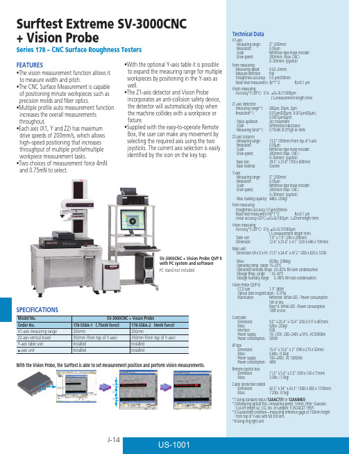
SV-3000CNC + Vision Probe QVP II with PC system and softwarePC stand not includedCJ-15The VISIONPAK software package processes the QVP to automatically detect the edges of features, and the general-VISIONPAK’s range of image processing tools makes it possible to quickly detect simple or complex edges When measuring very small shapes, removing burrs and dust on the measured object is difficult, and such imperfections can cause measurement errors. VISIONPAK can recognize these imperfections as outliers to prevent such errors.The Z-axis detector and QVP II include a safety device that prevents damage by automatically turning off the equipment if the detector is in danger of colliding with a workpiece or jig.The vision probe has been specially designed for use withCNC form measuring machines and incorporates the knowledge gained through many years of experience with coordinate measuring machines and image measuring VISION PROBE QVP IIPowerful image processing toolsOutlier removalBuilt-in safety mechanismAutomatic edge detectionVISIONPAK Image Processing ToolsA bright, long-life whit A bright, long-life white LED is standard equipmentThe standard QVP II is equipped with co-axial illumination directed down through the lens, and a ring light is available as an option. The illumination brightness is adjustable.The ring light and ML 10× objective lens shown mounted are optional items.Simple toolManual toolDetects an arbitrary edge pointed to (clicked on) by the mouse.Detects a single point on the edge Box toolCentroid toolDetects the center of area of an arbitrary form.rectangular box and creates multiple points along that edge.Circle toolEdge self-tracing toolBy simply specifying the start point and measurement interval, the target edge can be detected while automatically tracing an unknown geometry.The detector’s stylus tip* location can be conveniently aligned with the QVP II crosshairs on the monitor image Aligning the detector with the QVP IICCD size 1/3 inch (B/W)Optical tube magnifi cation0.375X。
CN正泰继电器手册

Page 142 JMK 通用型小型大功率 电磁继电器
Page 146
KG10D 时控开关
Page 115 KG316T 时控开关
Page 118
JYB-714 系列液位 继电器 Page 123
JZF 系列正反转 控制继电器 Page 126
额定控制电源电压 功能代号: X:相序 断相 三相不平衡保护 设计序号 继电器 企业代号
三相、三线模式:380,400,415,480VAC 三相、四线模式:220,230,240,277VAC 不平衡率:2%~22% 0.1~30s可调 1组转换触点 Ue/Ie:AC-15 220V/0.75A,380V/0.47A;Ith:3A 电源:绿LED,继电器输出:黄LED,报警指示:红LED -5℃~+40℃ 装置式或导轨式
Page 071 JS14S 系列时间 继电器
Page 075 JS11 系列时间 继电器
Page 078
计数器、累时器
NJJ1 计数继电器
Page 083 NJJ5-J 电子式计数器
Page 091 NJJ6 计数继电器
Page 095 JDM1-6 电子式计数器
Page 102 JDM1-14 计数继电器
断相与欠压、相序保护继电器
NJYB1 系列电压保护 继电器
XJ3 系列断相与 相序保护继电器
Page 048
时间继电器
NJS6 系列时间 继电器
Page 050
NJS3 系列时间 继电器
Page 052
NJS2 系列时间 继电器
Page 055
NJS1 系列时间 继电器
扑风Multiwash 14 产品说明书

CONTENTSPage information 3 Product3adviceI mportantsafetytheoperator 3 forGuidelinesprinciple 3 Workingyourmachine 4 Know5 usePreparingforAssembly 5 Controls 67 Operatingmachinemachine 8 theofCareMaintenance 8 Brushguide 9 selectionidentification 9 Brush10 AccessoriesAfter10 servicesales11 Electricaldiagram12 TechnicalspecificationsThis symbol is used in this manual to identifyparticular areas that are essential for your safety. Please pass all safety instructions on to other persons operating this machine.The Powr-Flite floor cleaning machines are designed for use on smooth, even floors in indoor areas. They can be used on most floor surfaces including short pile carpet, wood, rubber and stone. They should not be used on rough uneven surfaces.We are confident the machines will give years of trouble free service, coupled with ease of use and minimum maintenance.Equipment must be operated, serviced and maintained in accordance with the manufacturer’s instructions. If in doubt, contact the supplier of your machine.The following instructions contain important information about the machine and safety advice for the operator.• The machine must be unpacked and assembled inaccordance with these instructions before connecting to the electrical supply.• This machine should always be connected to a fully grounded power supply of the right voltage andfrequency.• Keep the power supply cord away from moving parts.During operation, hazard may occur when runningmachine over the power cord.• The machine must be disconnected from the power outlet (by pulling the plug out) before changing thebrushes, cleaning the machine or performing routine maintenance.• Warning! O nly use brushes/accessories as per theinstruction manual. Usage of any other brushes/accessories can cause safety problems.• Periodically inspect the cord for possible damage.A damaged cord must be replaced with the propercord available from the manufacturer or an authorized service agent.• D O NOT leave the machine connected to the power supply when not in use; always remove the plug from •DO NOT use where hazardous dust is present.• DO NOT use machine near flammable liquids.• DO NOT use in an explosive atmosphere.• DO NOTuse on a gradient or slopes.GUIDELINES FOR THE OPERATOR• Operators must be fully trained in accordance withthese instructions, able to perform routine upkeep ofthe machine and correct selection of brushes.• Operators should be physically capable to maneuver,transport and operate the machine.• DO NOT run the machine dry, as this could damagethe floor surface or the machine itself.• Take adequate care to hold the machine firmly whileinstalling and removing the brushes.• Never use excessive foaming or highly corrosivecleaning solutions.• While operating on a flooded floor, always ensure thatthe water level does not exceed 1/4" or 6 mm.• DO NOT operate this machine on rough unevensurfaces e.g. industrial concrete floors.• DO NOT clean the machine using pressure washers orsteam cleaners.• Ensure all parts are fitted properly before operation.ELECTRICAL CONNECTIONSBefore connecting the machine to the power supply,check that your supply voltage corresponds with thatmarked on the rating label on the body of the machine.IMPORTANT!READ THESE INSTRUCTIONS AND RETAIN FOR FUTURE REFERENCEand collects the dirty water.(4)(1)(2)(3)(10)(9)(8)(6)(5)(7)(1) Top handle(2) Solution control handle (3) Solution tank (4) Bottom handle (5) Dirty water tank (6) Inline solution filter (7) Component housing (8) Conveyor drum (9) Brush(10) Handle release pedal(5)PREPARING FOR USEincluded.2. Remove the hook, which holds the bottom handle with the machine body, while holding the bottom handle.UNPACKASSEMBLY1. Insert the two tubular handles into the bottom handle and secure them using handle knobs (12) by tightening lightly. Verify that the handles are assembled according to their marked position and the cable holding hooks are pointing towards the rear.2. Slide the electric cable retainer into the top portion of RH handle.3. Fit the top handle over the tubular handles and secure them with a washer and screw (2 sets). Ensure that the label on the top handle is facing the front of the machine. Now firmly tighten both the knobs and screws alternately. Insert the dummy caps provided to cover the screws (2) in the top handle.4. Pass the free end of the pull cable through the plastic guide in RH Handle. Press and twist clockwise to firmly secure the cable end to the fitting in the component housing.5. Fix the auxiliary tank firmly into the bottom handle by holding the top handle.6. Rotate the knob to hold the auxiliary tank.7. The brushes are only loosely packed in the machine for transit. The brush shafts must be fitted before operating the machine. Push the shafts through the brushes from the side of the machine. To remove brushes, push the brush shaft out from the side of the machine and remove the shaft. Normally the standard brush will be supplied with the machine. Brushes should be selected according to the type of floor surface to be cleaned and the type of dirt to be removed. Please refer Brush Selection Guide. 8. The machine is now ready for use.RIGHT BOTTOM REAR LEFT BOTTOM REARRelease the pedal handle lightly with your foot (1), pull back the handle (2) to start the motor. The brushes and the drum starts rotating. Pulling the handle further without pressing the pedal, lowers the machine and engages the rotating brushes onto the floor. To stop working, take the handle to the vertical position.On/Off ControlInsert the free end of solution cable into the valve body fitted in the auxiliary tank. Pressand twist clockwise to secure the cable end. Similarly, press and twist counter-clockwise to disconnect the cable end.Slide this knob to TOP position (Working Mode) to operate the machine. Slide this knob to BOTTOM position to move the machine and park the machine.Warning! Keeping the knob in the top position (working mode) and moving the machine will damage the brushes.Brush contact with the floor is adjustable in 4 steps, contact is MINIMUM when the knob is fully down and MAXIMUM when it is fully raised. This helps you to compensate for the wear of brushes and also to control the scrubbing effect. If the machine does not move when the handle is lowered, slide the transport/working mode knob up one step.By pulling the solution control handle up, the cleaning solution is dispensed on the floor. The solution stops once the solution control handle is released.In the event of motor getting overloaded due to improper power supply or unexpectedobstruction to the brush/drum rotation, the circuit breaker trips and protects the motor from damage. If this happens, identify the cause, correct it and, reset the breaker after minimum of 30 seconds from tripping by pressing the circuit breaker button manually and continue working.1. Move the Transport / Working mode control knob to BOTTOM (Transport) position (Fig-viii).2. Disconnect the power supply by unplugging the electrical plug and wind the cable over cable holders in the handle.3. Pull out the dirty water tank and wash it completely.4. To prevent possible clogging of filter, drain cleaning liquid and keep the fresh watertank clean. 5. Remove the brushes by pushing the brush shaft out (Fig-ix).6. Wash the brushes either by dipping in a bucket/sink or in running water (Fig-x).7. Turn the machine sideways and wipe clean the conveyor and machine body with a damp cloth (Fig-xi).8. Re-install the brushes after washing. It is easier to push the brush shaft from the right hand side (identified by the electrical cable).9. Store the machine in a dry indoor area only.MAINTENANCERegularly inspect power cord, plug and strain relief for damage or loose connection.• BrushesFor maximum life, wash the brushes regularly. Ensure machine is in Transport mode when not in use. Store additional brushes in a vertical position to avoid bending of bristles. Check for permanent bending of bristles in a particular direction. This may occur if the machine is operated for several days without removing thebrushes, which is not recommended. If this occurs, reverse the brush so that the bent bristles are automatically straightened.• Wiper BladeAfter years of use the wiper blade may wear. If this occurs the water collection performance will decrease. It should be replaced by an authorized service agent.• Solution tank filterThe filter prevents clogging of the drip holes in the tank. Periodically clean the filter to ensure uniform discharge of liquid. In case of non uniform discharge from the drip holes, back flush the tank in running water. Clean the drip holes using wire or a blunt pin.This is applicable when the customer has more than one set of brushes of same type.Distinct color coding make it easy to separate tools into their correct areas of use. Restroom brushes are kept in the restroom, kitchen brushes are kept in the kitchen - reducing bacteria cross-contamination between high and low-risk areas. RED, BLUE, WHITE and YELLOW brush buttons are packed with the machine. Simply plug the buttons into the hole in the brush as shown.Clear identification, by color coding, helps to prevent cross contamination.(a) Hole provided for plugging button.(b) Brush with button plugged.The transport cart provides for ease of movement when transporting the machine.Transport CartUsing the transport cart1. With the machine handle in the upright position place the cart centrally alongside the machine.2. By holding the machine firmly, tilt the handle away from your body. Slide the cart base under the machine and strap it to the machine with the velcro.3. Ensure that the velcro strap is securely wrapped around the bottom handle.4. Now the cart is ready to use. The machine can then be maneuvered easily while holding the top handle.Side BrushTo clean up to walls, the side brush may be used. Switch off and unplug the machine before fitting the side brush.1. Remove the front brush and brush shaft.2. Fix the shield assembly on the side plate.3. Insert the side brush through the shield and main ing the side brush1. Tilt the machine at an angle, move forward. This way, the dirty waterthrown by the side brush will be collected by the rear brush.2. Use side brush only for washing the edgesAFTER SALES SERVICEShould you require after sales service please contact the supplier from whom you purchased the machine, whowill arrange service. Repairs and servicing should only be performed by trained staff. Improper repairs can cause considerable danger to the user and void any warranty.treated as house hold waste. Instead it shall be handed over to applicable collection point for recycling of electrical and electronic equipment. By ensuring this product is disposed of correctly, you will help prevent potential negative consequence of the environment and 1. Electrical layoutDiagrams are made available in the cover (Power cord side) of the respective machine for service purpose.*TheoreticalNote:1. Noise levels measured at a distance of 3.28 feet from machine and 5.25 feet above floor, when washing a hard floor. Measurements recorded using a hand held meter.2. Handle vibration does not exceed 2.5 m/s2, when operating on a smooth hard surface.3. Above dimensions are approx. Since the companies policy is to continuously improve the product, there could be changes without prior notice.12。
洗衣机控制系统设计.

电气控制技术课程设计说明书题目:洗衣机控制系统设计学院:机电工程学院专业:电气工程及其自动化姓名:学号:指导教师:完成日期:2014年5月22日目录一、电气控制技术课程设计 ------------------------ 11.1、课程设计题目------------------------------------------------------------------------- 11.2 设计任务 ------------------------------------------------------------------------------ 11.3 课程设计的目的---------------------------------------------------------------------- 11.4 设计的要求 --------------------------------------------------------------------------- 11.5 技术难点 ------------------------------------------------------------------------------ 1二、电气控制原理图 ------------------------------ 22.1 设计过程中应遵循的原则----------------------------------------------------------- 22.2 主电路设计过程---------------------------------------------------------------------- 22.3控制电路 -------------------------------------------------------------------------------- 4三、电气控制板的制作及操作说明 ------------------ 43.1、控制板安装原则 -------------------------------------------------------------------- 43.2、安装过程中应注意以下几点-------------------------------------------------------- 53.3元器件选型 ----------------------------------------------------------------------------- 53.4本次设计电气控制板制作如下图----------------------------------------------------- 6四、 PLC程序设计--------------------------------- 74.1 PLC选择及I/O端口分配------------------------------------------------------------- 74.1.1 PLC的选择 --------------------------------------------------------------------- 74.1.2 I/O端口的分配---------------------------------------------------------------- 74.2 PLC编程的设计------------------------------------------------------------------------ 74.2.1 PLC的外围接线图------------------------------------------------------------- 74.2.2 PLC编程基本原则------------------------------------------------------------- 74.2.3 PLC编程的总程序------------------------------------------------------------- 84.3 PLC的上机程序图调试 -------------------------------------------------------------- 94.3.1连接好PLC时,程序图调试前如图 ----------------------------------------- 94.3.2开始运行时的PLC程序的调试---------------------------------------------- 11五、小结 ---------------------------------------- 13六、参考文献 ------------------------------------ 14一、电气控制技术课程设计1.1、课程设计题目:洗衣机控制系统设计1.2 设计任务:1.电动机功率为1.5KW,全压启动且为正反方向旋转2. 有两种洗涤模式:强洗、轻洗3.强洗是先正转2分钟,停15秒后反转2分钟,连续工作10分钟后停止工作。
JS14P系列数字式时间继电器

JS14P系列数字式时间继电器
适用范围
JS14P系列数字式时间继电器具有延时精度高、延时范围宽、接点容量大、
调整方便、工作状态直观、指示清晰明确等特点。
可广泛用于程序控制系统、
电拖动系统以及各处生产工艺过程的自动控制系统中,作为时间控制元件。
符合标准:GB14048.5、JB/T10047
型号及其含义
基本规格代号
派生代号
主要技术参数
1. 额定控制电源电压:交流50Hz、24、36、48、110、127、220、380;直流12、24、48、110、220V;
2. 延时误差:整定值小于1s时,延时误差不大于0.05s;整定值大于1s;误差小于±1%;
3. 输出接点数:两对转换接点;
4. 输出接点容量:直流30V、5A;交流220V、3A;
5. 电寿命:20万次;
6. 电源电压允许变化范围:85%~110%的额定电压;
7. 直流电纹波系数不应大于6%;
8. JS14P系列时间继电器规格技术数据见表3。
外形及安装尺寸
继电器外形尺寸见图1及图2,安装开孔尺寸见图3及图4,安装接线见图5及图6.
图1. 装置式JS14P-□/□,
JS14P-□/□Z继电器安装开孔尺寸
图2. 面板式JS14P-□-□M,JS14P-□/□ZM继电器外形尺寸
图3. 装置式JS14P-□/□,
JS14P-□/□Z继电器安装开孔尺寸
图4. 装置式JS14P-□/□M,JS14P-□/□ZM继电器安装开孔尺。
德力西JS14P 系列时间继电器 英文说明书

JS14P Series Time RelayUser Manual□ Please carefully read this User Manual before installing and operating the product. and keep this manual properly for future referenceI. Overview1.1 Scope of ApplicationJS14P series time relay is suitable for AC 50/60Hz automatic control circuit with the voltage 380V and below and with the DC volage 240 and below. and is used to connect or disconnect the circuit at a predetermined time.The product is an upgraded product such as JS14 and JS20. It uses integrated circuit and preset digital key switch. featuring with small size. light weight. high precision. long life and high versatility.Standard: GB/T 14048.51.2 Model definitionRated control supply voltage Us: see 3.3Delay time: see tableInstallation form: no code means device type; M means panel typeDelay type model and specification code: no code means power-on delay;D means power-off delayDigital typeDesign No.Time relaySpec. and Code Delay range Multiplyselection Setting methodDelay timeJS14P. JS14P-MJS14P-01 JS14P-01/М0.1-9.9s1-99sх0.1х12-digit settingswitchJS14P-02 JS14P-02/М0.1-9.9s0.1-9.9minх0.1х62-digit settingswitch 0.1-9.9s, 1-99s, 10-999s,0.1-9.9min, 1-99min,10-990min, 0.1-9.9h, 1-99h,0.01-9.99s, 0.1-99.9s, 1-999s,10-9990s, 0.1-99.9min,1-999min, 10-9990min,0.1-99.9h, 1-999h, One machinewith multiple delays 0.1s~99h,One machine with multipledelays 0.01s~999hJS14P-03 JS14P-03/М1-99s0.1-9.9minх1х62-digit settingswitchJS14P-04 JS14P-04/М0.1-9.9min1-99minх6х602-digit settingswitchJS14P-05 JS14P-05/М0.1-99.9s1-999sх0.1х13-digit settingswitchJS14P-06 JS14P-06/М1-999s10-9990sх1х103-digit settingswitchJS14P-07 JS14P-07/М0.1-99.9min1-999minх6х603-digit settingswitchJS14Р-D JS14Р-DМDelay time 0.1s-9.9s, 1s-99s, 0.01s-9.99s, 0.ls-999s, 1s- 599s1.3 Normal Working Conditions and Installation Conditions1.3.1 Working environment: the altitude does not exceed 2000 meters; the ambient temperature is not higher than +40°C and not below -5°C; the voltage variation range of the rated control power supply is 85%-110% of the rated voltage; Installed in places where there is no explosive medium or the medium does not contain gas or conductive dust that causes metal corrosion or damage to the insulation free from the rain or snow erosion.1.3.2 Vertical or horizontal installation.II. Structure Features and Working PrincipleThis series of time relays all uses medium-scale integrated circuits. LED light-emitting diode indication. digital toggle switch preset. featuring with convenient setting. stable and reliable operation. high delay precision. and small size.III. Technical Features3.1 Rated insulation voltage Ui: AC380V3.2 Rated impulse withstand voltage Uimp: AC2.5kV3.3 Rated control power supply voltage Us: AC: 380V, 220V, 127V, 110V, 36V, 24V, 12V; DC: 220V, 127V, 110V, 36V, 24V, 12V; AC/DC24V~48V; AC/DC100V~240V.3.4 The rated operating voltage Ue / rated operating current under the usage category Ie:AC-15 Ue: AC380V, Ie: 0.95A; Ue: AC240V, Ie: 1.5A; Ue: AC120V, Ie:3A;DC-13 Ue: DC250, Ie: 0.27A; Ue: DC125V, Ie: 0.55A3.5 Resistive current Ith: 5A3.6 Contact capacity: AC250V 3A; (resistive);3.7 Pollution level: 33.8 Setting error: ≤1%;3.9 Repetitive error: ≤1%;3.10 Mechanical life: ≥1 million times3.11 Electrical life: ≥100,000 times3.12 Cooperation with the short circuit protective device (SCPD): The RT16-00, 6A fuse with “1” type basic protection is recommended as SCPD; that is, the relay shall not cause danger to the persons or equipment in case of short circuit, and it is not allowed to work continuously before the repair or replacement of parts. If the fuse protective device of the different model is selected, the original cooperation may fail.IV. Outline and Installation DimensionsUnit: (mm)8-φ4 holes are for back-panel wiring Time relayJS1P, JS14P-D Outline dimensions drawing Device type installation dimensions drawing(or a 35mm standard mounting rail used) JS1P-M, JS14P-D/M Outline dimensions drawing Panel type mounting hole sizes drawingTime relayMultiplePanel type mounting hole sizes drawing JS14P-01~07/M Panel type outline dimensions drawing8-φ4 holes are for back-panel wiringTime relayMultipleJS14-01~07 Device type outline dimensions drawing Device type installation dimensions drawing(or a 35mm standard mounting rail used) V. Installation and Operation Instructions5.1 Please install the product according to the size of the mounting hole.5.2 Properly connect the wire according to the wiring diagram. After each wiring terminal is connected. the connecting wire shall be sleeved with an insulating bush firmly. When installing the plug and socket. please align with the pins to prevent accidents caused by short circuit of the power supply.5.3 Check that the power supply voltage must be consistent with the rated power supply voltage of the product;5.4 Power-on delay type: Please present all required delay time before use. and then turn on the power; at this time the relay delay starts; when the preset time expires. the delay contact is converted to realize timing control.5.5 Power-off delay type: preset the required delay time. and then turn on the power; at this time. the relay delay contact will pull in. and the charging capacitor starts to charge; when the charging time exceeds 5 seconds. cut off the control power supply of product. and at this time the relay starts to delay; when the delay time reaches the preset value. the relay delay contact is converted to the release state to realize the timing control; this state will be maintained until the relay contact pulls in again when the next startup.5.6 Operation Precautions:1) Be sure to weld the control line of the terminal block when wiring;2) It is forbidden to install or dismantle the energized product.3) The operating voltage of the relay shall be within the rated operating voltage range during operation.4) The equipment that may cause major economic losses or personal safety is designed to make the technical characteristics and performance values have sufficient allowance. and safety measures such as double circuit protection should be adopted.JS14P-01~07, JS14P device type wiring diagram JS14P-01-07M, JS14P-M wiring diagram JS14P-D wiring diagram JS14P-D/M wiring diagramVI. Common Faults and Troubleshooting6.1 Not work after startupThe power terminal is not wired and the wiring is improperly connected or disconnected. and the power supply is not connected.6.2 The relay works abnormally after power-onCheck the relay wiring connection and digital setting are correct; check the product for broken line or short circuit.6.3 TroubleshootingIn case of failure of product. first cut off the power. and then find the cause of the failure; operate the product according to the Installation and Operation Instructions after checking that the line works normally.If the product has the poor quality problem. please contact the local dealer or our company.VII. Transport and StorageThe product shall be free from the rain or snow erosion or squeezing during storage and transportation. and shall be stored in well ventilated places where the relative humidity (25℃±5℃) does not exceed 90%. the lower limit of the temperature is -25℃. and the upper limit of the temperature is +55℃.VIII. Unpacking and InspectionOpen the outer carton and check that there is the Operation Instruction in the packing box.IX. Ordering NoticePlease specify the model and specification of the product when ordering. For Any special requirement. please contact the manufacturer.X. Company CommitmentUnder the condition that users follow the use and storage conditions and the product are well sealed. within 24 months from the production date. our company will provide repair and replacement service free of charge for any damage or abnormal operation due to poor manufacture quality. A paid repair will be provided if the warranty period expires. For any damage due to one of the following situations. a paid repair will be given even if within the warranty period:(1)Improper operation. maintenance. or storage;(2)Modified without permission or improper repair;(3)Damage due to falling off or caused during installation after purchase;(4)Force majeure such as earthquakes. fires. lightning strikes. abnormal voltages. and secondary disasters;(5)The electrical life of the product exceeds 100.000 times; The mechanical life is more than one million times. If you have any question. please contact the dealer or our company’s customer service department.Customer Service Hotline: 400-826-8008Certificate DELIXI GROUP CO., : Time RelayModel: JS14P SeriesThis product complies with the GB/T 14048.5 standard. passes the inspection and is allowed to be shipped Inspector: Check 01Production date: See label on inner boxManufacturer: Zhejiang Delixi Electrical Co., Ltd.Address: No. 155. Zhandong Road. Liushi Town. Yueqing City. Zhejiang P/C: 325604 Tel: (86-577) 61778888Fax: (86-577) 61778000Customer Service Hotline: 400-826-8008The second edition of this User Manual was issued in Aug. 2021.。
高压操作电路栅极放大器 SG143 数据手册说明书
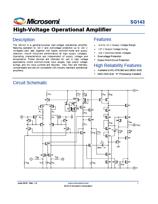
The SG143 is a general-purpose high-voltage operational amplifier featuring operation to ±40 V and overvoltage protection up to ±40 V. Increased slew rate, together with higher common-mode and supply rejection, insure improved performance at high supply voltages. Operating characteristics are independent of supply voltage and temperature. These devices are intended for use in high voltage applications where common-mode input ranges, high output voltage swings, and low input currents are required. Also, they are internally compensated and are pin compatible with industry standard operational amplifiers.High-Voltage Operational AmplifierSG143Description FeaturesJune 2015 Rev. 1.21 © 2015 Microsemi Corporation▪▪▪▪Overvoltage Protection±37 V Output Voltage Swing ±24 V Common-Mode Voltages ▪Output Short-Circuit ProtectionHigh Reliability Features▪Available to MIL-STD-883 and DESC SMD ▪MSC-AMS level "S" P rocessing A vailableCircuit Schematic3 k4.7 k20 pF±4.0 to ±40 V Supply Voltage RangeF igure5.I nput C urrentF igure 6. V oltageG ainF igure 1. P ower B andwidth F igure 2. P eak O utput V oltage S wing vs . P ower S upply V oltageF igure 4. O utput S hort -C ircuit C urrent vs . T emperatureF igure 3. O pen -L oop F requency R esponseCharacteristic Curves10 k+28 VV5 k Ω±28 VV 100 kΩ1.0 10 100 1.0 k 10 k 100 k 1.0 M 10 M 100 MNote 1. Contact factory for DESC product availablity.2. All packages are viewed from the top.F igure 8. U nityG ain B andwidthF igure 7. S upply C urrentAmbientTemperature Range Part No.PackageConnection Diagram-55°C to 125°C -55°C to 125°C SG143T -883B SG143T -DESC SG143T-55°C to 125°C8-PIN METAL CAN T - PACKAGEOUTPUTV+48517326INVERTING INPUT V -OFFSET ADJUST NON-INVERTING INPUTOFFSET ADJUSTN.C.8-PIN CERAMIC DIP Y- PACKAGESG143Y -DESC-55°C to 125°C87652134INVERTING INPUT OFFSET ADJUSTNON-INVERTING INPUTV-V+OFFSET ADJUSTOUTPUTN.C.F igure 11 - L ow - D rift S ample and H oldF igure 10 - D ifferential A mplifier with ±20 VF igure 9 - V oltage O ffset N ull C ircuitCharacteristic Curves (Continued)Typical ApplicationsConnection Diagrams and Ordering Information (See Notes Below )±28 V ±28 V10 k+28 V+28 V28 V10 k4.7 k10 k28 V100 kC ommon -M ode I nput V oltage R ange8 mV/s1.0 µF3.These hermetic packages use Sn63/Pb37 hot solder lead finish, contact factory for availability of RoHS versions.Microsemi Corporate Headquarters One Enterprise, Aliso Viejo,CA 92656 USAWithin the USA: +1 (800) 713-4113 Outside the USA: +1 (949) 380-6100 Sales: +1 (949) 380-6136Fax: +1 (949) 215-4996E-mail: ***************************Microsemi Corporation (MSCC) offers a comprehensive portfolio of semiconductor and system solutions for communications, defense & security, aerospace and industrial markets. Products include high-performance and radiation-hardened analog mixed-signal integrated circuits, FPGAs, SoCs and ASICs; power management products; timing and synchronization devices and precise time solutions, setting the world's standard for time; voice processing devices; RF solutions; discrete components; security technologies and scalable anti-tamper products; Ethernet solutions; Power-over-Ethernet ICs and midspans; as well as custom design capabilities and services. Microsemi is headquartered in Aliso Viejo, Calif., and has approximately 3,600 employees globally. Learn more at .© 2015 Microsemi Corporation. All rights reserved. Microsemi and the Microsemi logo are trademarks of Microsemi Corporation. All other trademarks and service marks are the property of their respective owners.Microsemi makes no warranty, representation, or guarantee regarding the information contained herein or the suitability of its products and services for any particular purpose, nor does Microsemi assume any liability whatsoever arising out of the application or use of any product or circuit. The products sold hereunder and any other products sold by Microsemi have been subject to limited testing and should not be used in conjunction with mission-critical equipment or applications. Any performance specifications are believed to be reliable but are not verified, and Buyer must conduct and complete all performance and other testing of the products, alone and together with, or installed in, any end-products. Buyer shall not rely on any data and performance specifications or parameters provided by Microsemi. It is the Buyer's responsibility to independently determine suitability of any products and to test and verify the same. The information provided by Microsemi hereunder is provided "as is, where is" and with all faults, and the entire risk associated with such information is entirely with the Buyer. Microsemi does not grant, explicitly or implicitly, to any party any patent rights, licenses, or any other IP rights, whether with regard to such information itself or anything described by such information. Information provided in this document is proprietary to Microsemi, and Microsemi reserves the right to make any changes to the information in this document or to any products and services at any time without notice.。
人民电器 JS14P系列时间继电器 产品说明书
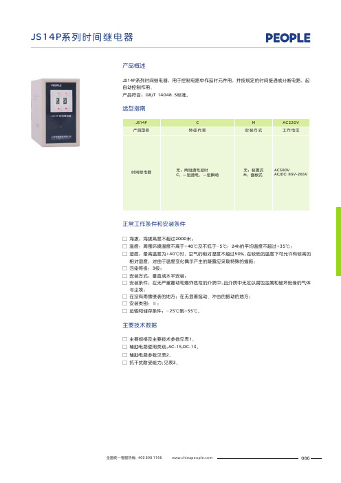
JS14P系列时间继电器,用于控制电路中作延时元件用,并按规定的时间接通或分断电路,起自动控制作用。
产品符合:GB/T14048.5标准。
□ 辅助电路使用类别:AC-15,DC-13。
□ 辅助电路参数见表2。
□ 抗干扰耐受能力:见表3。
□ 主要规格及主要技术参数见表1。
□ 海拔:海拔高度不超过2000米;
□ 温度:周围环境温度不高于+40℃及不低于-5℃;24h的平均温度不超过+35℃;
□ 湿度:最高温度为+40℃时,空气的相对湿度不超过50%,在较低的温度下可允许有较高的 相对湿度,对由于温度变化偶尔产生的凝露应采取特殊的措施;
□ 污染等级:3级;
□ 安装方式:垂直或水平安装;
□ 安装条件:在无严重震动和爆炸危险的介质中,且介质中无足以腐蚀金属和破坏绝缘的气体 与尘埃;
□ 在没有雨雪侵袭的地方;在无显著摇动、冲击的振动的地方;
□ 安装类别:Ⅱ;
□ 运输和储存条件:-25℃到+55℃。
正常工作条件和安装条件
主要技术数据
产品概述
选型指南
086
图1 JS14P 外形尺寸
图2 JS14P-M 外形尺寸
087
表3
表2
表1
外形及安装尺寸
装置式面板式(JS14P-C瞬动触点为3、4、5)
图4 接线图
图3 安装尺寸图
面板式
装置式
接线图
订货须知
用户订货时必须说明
□ 时间继电器的名称及型号;
□ 时间继电器的延时时间、额定控制电源电压(V);
□ 所需购买的数量。
例如:JS14P99s AC220V 数量500台。
088。
JS14P系列 时间继电器 说明书
JS14P JS14P-M
延时范围 0.1s~9.9s、1s~99s 0.1s~9.9s、10s~990s 1s~99s、10s~990s 10s~990s、1min~99min 0.1s~99.9s、1s~999s 1s~999s、10s~9990s 10s~9990s、1min~999min
注:a.本产品部分型号适用于宽范围工作电压,如工作电压在AC/DC24V~48V表示交直流24V至48V的电 压范围内都可以正常工作。 b.订购时JS14P-21~27产品不需注延时规格。
3 主要参数及技术性能
技术参数
工作方式 触点数量 触点容量 工作电压 电寿命 机械寿命 延时精度 环境温度 安装方式
JS14P系列 时间继电器
继电器类
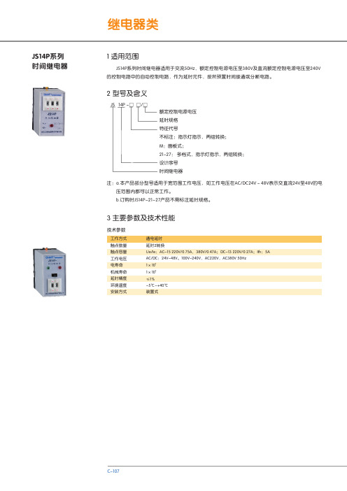
1 适用范围
JS14P系列时间继电器适用于交流50Hz,额定控制电源电压至380V及直流额定控制电源电压至240V 的控制电路中的自动控制电路,作为延时元件,按所预置时间接通或分断电路。
2 型号及含义
JS 14P -□ □/□
额定控制电源电压 延时规格 特征代号 不标注:指示灯指示,两组转换; M:面板式; 21~27: 多档式,指示灯指示,两组转换; 设计序号 时间继电器
55±0.4 ≥90
C-108
继电器类
R
JS14P-21
时间继电器
×0.1
×1
-99 ++
45max
R
JS14P-M 时间继电器
电压 延时
AC220V 99s
-99 ++
JS14P 系列数字式时间继电器
48
Delixi Electric
JS14P 系列数字式时间继电器
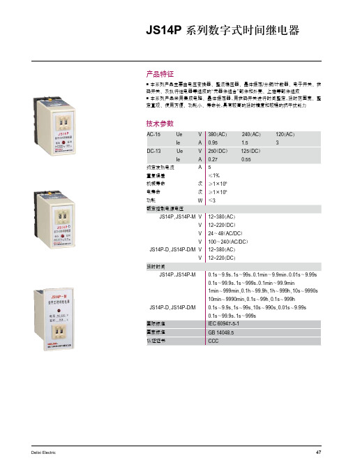
产品特征
本系列产品主要由电压变换器、整流稳压器、晶体振荡/分频/计数器、电子开关、拨 码开关、及执行继电器等组成的“元器件组合”部件和外壳、上插等部件组成 本系列产品采用集成电路、晶体振荡器,用拨码开关进行时间整定,延时范围宽、整 定直观、使用方便、功耗小、寿命长,具有较高的延时精度和较强的抗干扰能力
1min~999min、0.1h~99.9h、1h~999h、10s~9990s
10min~9990min、0.1s~99h、0.1s~999h
JS14P-D、JS14P-D/M
0.1s~9.9s、1s~99s、10s~990s、0.01s~9.99s
国际标准
0.1s~99.9s、1s~999s IEC 60947-5-1
技术参数
AC-15ห้องสมุดไป่ตู้
Ue
V 380(AC)
240(AC)
120(AC)
Ie
A 0.95
1.5
3
DC-13
Ue
V 250(DC) 125(DC)
Ie
A 0.27
0.55
约定发热电流
A5
重复误差 机械寿命 电寿命
≤1% 次 ≥1×10⁶ 次 ≥1×10⁵
功耗
W ≤3
额定控制电源电压
JS14P、JS14P-M V 12~380(AC)
V 12~220(DC)
V 24~48(AC/DC)
V 100~240(AC/DC)
JS14P-D、JS14P-D/M V 12~380(AC)
V 12~220(DC)
延时时间
JS14P、JS14P-M
- 1、下载文档前请自行甄别文档内容的完整性,平台不提供额外的编辑、内容补充、找答案等附加服务。
- 2、"仅部分预览"的文档,不可在线预览部分如存在完整性等问题,可反馈申请退款(可完整预览的文档不适用该条件!)。
- 3、如文档侵犯您的权益,请联系客服反馈,我们会尽快为您处理(人工客服工作时间:9:00-18:30)。
JS14P数字式时间继电器
适用范围
JS14P数字式时间继电器是JS14、JS20时间继电器等的更新换代产品。
采用集成电路,数字按键开关预置,具有工作稳定、精度高、延时范围宽、功耗低、外形美观、安装方便等特点,广泛应用于自动控制中作延时元件用。
符合GB14048.5标准。
型号及其含义
一些常见的JS14P数字式时间继电器型号有:
JS14P 19S/220V 时间继电器 JS14P 19S/380V 时间继电器
JS14P 9.9S/110V JS14P 9.9S/24V JS14P 9.9S/36V
JS14P 9.9S/DC24V JS14P 99.9S/110V JS14P 99.9S/220V
JS14P-M 99.9" 36V JS14P-M 99.9" 380V JS14P-M 99.9M 380V
JS14P-M 99.9M/220V JS14P-M 99.9S/DC24V JS14P-M 999M 220V
JS14P-M 999M 380V JS14P-M 999S/220V JS14P-M 999S/380V
JS14P-M 999S/DC24V JS14P-M 99M 220V JS14P-M 99M 380V
JS14P-M 99S/220v JS14P-M 99S/36V JS14P-M 99S/380v
JS14P-M 99S/DC24V
技术参数
1.电源电压:AC50Hz、36V、110V、127V、220V、380V、DC220V。
动作电压为(85~110%)额定控制电源电压;
2.触头电寿命:≥10万次;
3.机械寿命:≥100万次;
4.触头额定控制容量:AC15:100VA;DC13:20W;
5.功耗:≤5W;
6.使用环境:-5℃~+40℃。
7,延时范围
0.1s-9.9s、0.01s-9.99s、1s-99s、1s-999s、1m-99m、1m-999m
外形及安装尺寸
使用说明
先预置所需的延时时间,然后接通电源,此时继电器开始工作,当达到所预置的时间时,延时触头实行转换,实行定时控制。
如果你希望了解JS14P数字式时间继电器的更多内容,如产品使用说明书,规格参数,价格,更新等信息,请联系我们。