R8200数字中继中文说明
8200系列数字计量仪的输入切换应用(第一部分:DC计量仪)说明书
Application Brief - Switching Inputs to Digital Meters Part IUsing a Single 8200 Series Digital Meter to Monitor Multiple Voltages and CurrentsOverviewThis application note will be presented in two parts: Part One will deal with DC meters and Part Two will address AC meters. Both show how to expand the usefulness of the 8200 Series Digital Meters by supplying multiple voltages, shunt, and current transformer inputs through various switching arrangements. The installation manual for the specific meter being installed must be thoroughly understood before attempting any additional input switching. If the system is 120/240V AC please also review the article in Newsletter #6 titled "Understanding Current Flow In 120/240V AC Single Phase Systems". This technical brief will explain where to best install the required current transformers.Switching Inputs on DC MetersThe DC Digital Meters (Models 8235, 8236, 8248, and 8251) are powered by supplying 7-60 V DC to terminals #1 & #2 on the back of the meter. These terminals provide power to the internal electronics and microprocessor. The voltage sensing and current shunt inputs are supplied on other terminals and may be switched as desired to monitor multiple battery voltages and currents, provided they share a common negative and the shunts are installed in the negatives of the circuits to be measured.DC VoltageFor example suppose a system has a "house battery" and an engine starting battery. As long as the negatives of the two systems are connected together (common), you may switch the Voltage Sense Terminal #3 between the two batteries. This is true even if the batteries are different voltages. So, for our example let's assume a 24V starting system and a 12V house system, we can simply install a SPDT (Single Pole Double Throw) switch. Meter terminal #3 is connected to the common of the switch and the 12V and 24V sense leads from the batteries are connected to the other two poles. See Drawing #1. While we have shown this example with only two batteries any number of batteries may be switched to into terminal #3 Vsense. Switching in more than two batteries is most easily accomplished with a multiple position rotary switch. Also note that all ungrounded current carrying conductors must be supplied with over-current protection (note the fuse shown in each sense lead).DC CurrentMeasuring the current flow in and out of multiple batteries requires that a shunt be installed in the negative of each battery. (See the installation manual for a discussion of Current Shunts.) Also the shunts must be at the same negative potential; that is connected in common with each other. This is basically the same restriction as for voltage measurement, however because the signal is much smaller it is necessary to be sure that the current carrying connections between the shunts be short and of adequate size to not induce errors during large current flows.Drawing #2 illustrates how to wire two shunts into terminals #4 & #5. In the example, two batteries are shown with a shunt in the negative of each. A Double Pole Double Throw (DPDT) switch is used to connect one shunt, or the other, to the meter. You must use a Double Pole switch because both terminals from the shunts must be switched into terminals #4 and #5 of the meter. If more than two batteries are to be monitored use a double pole multiple position rotary switch.Back of Meter½ANegatives must be commonDrawing #1Switching DC Inputs to Terminal #3 VsenseNote: See manual for balance of wiring.Drawing #2Switching DC Shunt Inputs toTerminals #4 and #5Back of MeterNote: See manual for balance of wiring.。
MOTOTRBO R8200中转台基础维修手册

MDR 3000UHF Range 1MOTO TRBO™ RepeaterBasic Service Manual6866576D03-AForewordThis manual covers all models of the MOTOTRBO Repeater, unless otherwise specified. It includes all the information necessary to maintain peak product performance and maximum working time, using levels 1 and 2 maintenance procedures. This level of service goes down to the board replacement level and is typical of some local service centers, Motorola Authorized Dealers, self-maintained customers, and distributors.For details on repeater operation or component-level troubleshooting, refer to the applicable manuals available separately. Product Safety and RF Exposure ComplianceATTENTION!This repeater is restricted to occupational use only to satisfy ICNIRP/FCC RF energy exposure requirements. Before using this product, read the RF energy awareness information and operating instructions in the Product Safety and RF Exposure booklet enclosed with your product (Motorola Publication part number 6866537D37) to ensure compliance with RF energy exposure limits.For a list of Motorola-approved antennas, and other accessories, visit the following web site which lists approved accessories:/governmentandenterpriseComputer Software CopyrightsThe Motorola products described in this manual may include copyrighted Motorola computer programs stored in semiconductor memories or other media. Laws in the United States and other countries preserve for Motorola certain exclusive rights for copyrighted computer programs, including, but not limited to, the exclusive right to copy or reproduce in any form the copyrighted computer program. Accordingly, any copyrighted Motorola computer programs contained in the Motorola products described in this manual may not be copied, reproduced, modified, reverse-engineered, or distributed in any manner without the express written permission of Motorola. Furthermore, the purchase of Motorola products shall not be deemed to grant either directly or by implication, estoppel, or otherwise, any license under the copyrights, patents or patent applications of Motorola, except for the normal non-exclusive license to use that arises by operation of law in the sale of a product.Document CopyrightsNo duplication or distribution of this document or any portion thereof shall take place without the express written permission of Motorola. No part of this manual may be reproduced, distributed, or transmitted in any form or by any means, electronic or mechanical, for any purpose without the express written permission of Motorola.DisclaimerThe information in this document is carefully examined, and is believed to be entirely reliable. However, no responsibility is assumed for inaccuracies. Furthermore, Motorola reserves the right to make changes to any products herein to improve readability, function, or design. Motorola does not assume any liability arising out of the applications or use of any product or circuit described herein; nor does it cover any license under its patent rights nor the rights of others.TrademarksMOTOROLA and the Stylized M logo are registered in the U.S. Patent & Trademark Office. All other product or service names are the property of their respective owners.© 2007 by Motorola, Inc.All rights reserved.iii Document HistoryThe following major changes have been implemented in this manual since the previous edition:Edition Description Date 6866576D03-A Initial Release Feb. 20076866576D03-A February 21, 2007ivNotesFebruary 21, 20076866576D03-ATable of Contents v Table of Contents Foreword (ii)Product Safety and RF Exposure Compliance (ii)Computer Software Copyrights (ii)Document Copyrights (ii)Disclaimer (ii)Trademarks (ii)Document History (iii)Chapter 1Introduction.........................................................................1-11.1Notations Used in This Manual....................................................................................................1-11.2Repeater Description...................................................................................................................1-11.3MOTOTRBO Repeater Model Numbering Scheme.....................................................................1-21.4UHF1 High Power MOTOTRBO Repeater (403-470 MHz) Model Chart.....................................1-31.5Specifications...............................................................................................................................1-4 Chapter 2Test Equipment and Service Aids.....................................2-12.1Recommended Test Equipment..................................................................................................2-12.2Service Aids.................................................................................................................................2-22.3Programming Cables ..................................................................................................................2-2 Chapter 3Transceiver Performance Testing.....................................3-13.1General........................................................................................................................................3-13.2Setup...........................................................................................................................................3-1 Chapter 4Repeater Tuning and Programming..................................4-14.1Introduction..................................................................................................................................4-14.2Customer Programming Software Setup.....................................................................................4-14.3Repeater Tuning Setup................................................................................................................4-2 Chapter 5Disassembly/Reassembly Procedures.............................5-15.1Introduction..................................................................................................................................5-15.2Preventive Maintenance..............................................................................................................5-15.2.1Inspection........................................................................................................................5-15.2.2Cleaning Procedures.......................................................................................................5-15.3Safe Handling of CMOS and LDMOS Devices............................................................................5-25.4Repair Procedures and Techniques — General..........................................................................5-35.5Disassembling and Reassembling the Repeater — General......................................................5-4 6866576D03-A February 21, 2007vi Table of Contents5.6Disassembly Procedures — Detailed..........................................................................................5-45.6.1Disassembly of Cover......................................................................................................5-45.6.2Disassembly of Repeater Indicator Board.......................................................................5-55.6.3Disassembly of Fan.........................................................................................................5-65.6.4Removing Transmit Radio...............................................................................................5-75.6.4.1Removing Thermal Pad and Heatsink..............................................................5-85.6.5Removing Receive Radio, Power Supply and Connector Board Assembly....................5-85.6.5.1Disassembly of Receive Radio.......................................................................5-105.6.5.2Disassembly of Connector Board Assembly...................................................5-105.6.5.3Disassembly of Power Supply........................................................................5-105.7Transmit and Receive Radio Disassembly — Detailed.............................................................5-115.7.1Transceiver Board and Receiver Board Removal.........................................................5-115.8Transmit and Receive Radio Reassembly — Detailed..............................................................5-145.8.1Transceiver Board and Receiver Board Reassembly....................................................5-155.8.2Thermal Pad Replacement Procedure..........................................................................5-195.8.3Reassembly of Receive Radio, Power Supply and Connector Board Assembly...........5-215.8.3.1Reassembly of Power Supply.........................................................................5-215.8.3.2Reassembly of Receive Radio........................................................................5-215.8.3.3Reassembly of Connector Board Assembly...................................................5-215.8.3.4Reassembly of the Receive Bracket Assembly to the Enclosure...................5-215.8.4Reassembly of Transmit Radio......................................................................................5-225.8.4.1Replacing the Thermal Pad and Heatsink......................................................5-225.8.4.2Reassembly of the Transmit Bracket Assembly to the Enclosure..................5-225.8.5Reassembly of Fan........................................................................................................5-235.8.6Reassembly of Repeater Indicator Board......................................................................5-235.8.7Reassembly of Cover....................................................................................................5-235.9Repeater Exploded Mechanical Views and Parts Lists..............................................................5-245.10Torque Chart..............................................................................................................................5-27 Chapter 6Basic Troubleshooting.......................................................6-16.1Introduction..................................................................................................................................6-16.1.1High Power RF Precaution..............................................................................................6-16.2Replacement Service Kit Procedures..........................................................................................6-16.3LED Indicator Descriptions..........................................................................................................6-2Appendix A EMEA Regional Warranty, Service and Support..............A-1A.1Warranty and Service Support.....................................................................................................A-1A.2European Radio Support Centre (ERSC)....................................................................................A-2A.3Piece Parts...................................................................................................................................A-2A.4T echnical Support........................................................................................................................A-3A.5Further Assistance From Motorola...............................................................................................A-3Glossary.........................................................................................Glossary-1 February 21, 20076866576D03-Aviii List of Figures List of FiguresFigure 1-1.Repeater Model Numbering Scheme...................................................................................1-2 Figure 2-1.Mobile & Repeater Rear Programming Cable PMKN4010_................................................2-2 Figure 2-2.Mobile & Repeater Rear Programming, T esting & Alignment Cable PMKN4016_...............2-3 Figure 4-1.Customer Programming Software Setup from Rear Accessory Connector.........................4-1 Figure 4-2.Repeater Tuning Equipment Setup......................................................................................4-2 Figure 5-1.Removing T op Cover of Repeater Enclosure.......................................................................5-4 Figure 5-2.Disconnecting Ethernet Cable and Flex Cable....................................................................5-5 Figure 5-3.Repeater Indicator Board Disassembly................................................................................5-6 Figure 5-4.Fan Orientation.....................................................................................................................5-6 Figure 5-5.Tx Radio Disassembly.........................................................................................................5-7 Figure 5-6.Receive Radio Removal.......................................................................................................5-9 Figure 5-7.Die Cast Cover Removal....................................................................................................5-11 Figure 5-8.Accessory Connector Removal..........................................................................................5-12 Figure 5-9.RF/DC Retention Clips Removal........................................................................................5-12 Figure 5-10.Transceiver Board Removal...............................................................................................5-13 Figure 5-11.Thermal Pads and Shield Gasketing on Chassis and Die Cast Cover...............................5-14 Figure 5-12.Transceiver Board with Thermal Pads...............................................................................5-14 Figure 5-13.Replacing GPS Plug..........................................................................................................5-15 Figure 5-14.Placing the Transceiver Board in the Chassis....................................................................5-15 Figure 5-15.Inserting RF/DC Retention Clips........................................................................................5-16 Figure 5-16.Inserting Accessory Connector..........................................................................................5-16 Figure 5-17.Assembling of PA Pad and O-ring......................................................................................5-17 Figure 5-18.Assembling Die Cast Cover onto Chassis.........................................................................5-18 Figure 5-19.Screw Sequence to Tighten Die Cast Cover......................................................................5-19 Figure 5-20.Replacing Thermal Pads....................................................................................................5-19 Figure 5-21.Aligning Driver Pad on Chassis..........................................................................................5-20 Figure 5-22.Placing Thermal Pads on PA and Transistor Components................................................5-20 Figure 5-23.Fan Orientation...................................................................................................................5-23 Figure 5-24.Repeater Assembly Exploded View...................................................................................5-24 Figure 5-25.Receive Bracket and Radio Assembly Exploded View......................................................5-25 Figure 5-26.Transmit Bracket and Radio Assembly Exploded View......................................................5-25 Figure 5-27.Front Panel Complete Assembly Exploded View...............................................................5-26 February 21, 20076866576D03-AList of Tables ix List of TablesT able 1-1.Frequency Ranges and Power Levels.................................................................................1-1 T able 2-1.Recommended T est Equipment...........................................................................................2-1 T able 2-2.Service Aids.........................................................................................................................2-2 T able 3-1.Initial Equipment Control Settings........................................................................................3-1 T able 3-2.Receiver Performance Checks............................................................................................3-2 T able 4-1.Repeater Software Program Kits.........................................................................................4-1 T able 5-1.Lead Free Solder Wire Part Number List.............................................................................5-3 T able 5-2.Lead Free Solder Paste Part Number List...........................................................................5-3 T able 5-3.Repeater Exploded View Parts List....................................................................................5-26 T able 5-4.T orque Specifications for Nuts and Screws........................................................................5-27 T able 6-1.LED Indicator Descriptions...................................................................................................6-2 6866576D03-A February 21, 2007x Related Publications February 21, 20076866576D03-AChapter 1Introduction1.1Notations Used in This ManualThroughout the text in this publication, you will notice the use of note and caution notations. These notations are used to emphasize that safety hazards exist, and due care must be taken and observed.NOTE:An operational procedure, practice, or condition that is essential to emphasize.1.2Repeater DescriptionThe MOTOTRBO Repeater is Motorola’s newest two-way digital and analog repeater designed for your organization’s most demanding needs. The repeater is available in the following frequency ranges and power levels.This repeater is among the most sophisticated two-way repeaters available. It has a new robust design for users who need high performance, quality, and reliability in their daily communications. This new architecture provides the capability of supporting a multitude of legacy and advanced features resulting in a more cost-effective two-way repeater communications solution.Table 1-1. Frequency Ranges and Power LevelsFrequency BandBandwidthPower LevelUHF R1403–470MHz25-40Watts1-2Introduction: MOTOTRBO Repeater Model Numbering Scheme 1.3MOTOTRBO Repeater Model Numbering SchemeFigure 1-1. Repeater Model Numbering SchemeFebruary 21, 20076866576D03-AIntroduction: UHF1 High Power MOTOTRBO Repeater (403-470 MHz) Model Chart1-3 1.4UHF1 High Power MOTOTRBO Repeater (403-470 MHz) ModelChartUHF1 403-470 MHz, 25-40WModel DescriptionMDM27QPR9JA7AN403-470 MHz, 25-40W, MOTOTRBO RepeaterItem DescriptionX PMLN4815_Connector Board AssemblyX PMLN4814_Repeater Indicator BoardX PMUE2390_S Repeater Service KitX3002695D05NNTN7373_RNNTN7374_R Power Supply UK Power Supply US Power Supply EUX6866537D37Product Safety and RF Exposure BookletX = Item Included_ = the latest version kit. When ordering a kit, refer to your specific kit for the suffix number.6866576D03-A February 21, 20071.5SpecificationsGeneralSpecification UHF1Channel Capacity1T echnical RF Output25-40WFrequency403-470 MHzDimensions (HxWxL)132.6 mm x 482.6 mm x 296.5 mmWeight14 kgVoltage Requirements100-240 V AC 47-63 Hz (13.6 V DC)Current Drain: StandbyTransmit 0.5 A (1 A DC typical)1.5 A (11 A DC typical)Operating T emperature Range-30°C to +60°CMax Duty Cycle100%ReceiverSpecification UHF1Frequency403-470 MHzChannel Spacing12.5 kHz/25 kHzFrequency Stability (-30°C to +60°C)±0.5 ppmAnalog Sensitivity0.30 µV (12 dB SINAD)0.22 µV (typical) (12 dB SINAD)0.40 µV (20 dB SINAD)Digital Sensitivity5% BER: 0.3 µVIntermodulation70 dBAdjacent Channel Selectivity: 60 dB @ 12.5 kHz, 70 dB @ 25 kHzSpurious Rejection70 dBAudio Distortion @ Rated Audio3% (typical)Hum and Noise-40 dB @ 12.5 kHz-45 dB @ 25 kHzAudio Response+1, -3 dBConducted Spurious Emission-57 dBmFebruary 21, 20076866576D03-ATransmitterSpecification UHF1Frequency403-470 MHzChannel Spacing12.5 kHz/25 kHzFrequency Stability (-30°C to +60°C)±0.5 ppmPower Output25-40 WModulation Limiting±2.5 kHz @ 12.5 kHz±5.0 kHz @ 25 kHzFM Hum and Noise-40 dB @ 12.5 kHz-45 dB @ 25 kHzConducted/Radiated Emission-36 dBm < 1 GHz-30 dBm > 1 GHzAdjacent Channel Power60 dB @ 12.5 kHz70 dB @ 25 kHzAudio Response+1, -3 dBAudio Distortion3%Digital Vocoder Type AMBE++Digital Protocol ETSI-TS102 361-1Conforms to:ETSI TS 102 361 (Parts 1, 2 & 3) - ETSI DMR Standard1999/5/EC (R&TTE - Radio and T elecommunications T erminal Equipment)2002/95/EC (RohS - Banned Substances)2002/96/EC (WEEE - Waste Electrical and Electronic Equipment)94/62/EC (Packaging and Packaging Waste)Radio meets applicable regulatory requirements.Specifications subject to change without notice. All specfications shown are typical.6866576D03-A February 21, 2007NotesFebruary 21, 20076866576D03-AChapter 2Test Equipment and Service Aids2.1Recommended Test EquipmentThe list of equipment contained in T able 2-1 includes most of the standard test equipment required for servicing Motorola repeaters.Table 2-1. Recommended Test EquipmentEquipment Characteristic Example ApplicationService Monitor Can be used as asubstitute for itemsmarked with an asterisk(*)Aeroflex 2975(), MotorolaR2670, or equivalentFrequency/deviation meter andsignal generator for wide-rangetroubleshooting and alignmentDigital RMS Multimeter*100 µV to 300 V5 Hz to 1 MHz10 Meg Ohm ImpedanceFluke 179 or equivalent()AC/DC voltage and currentmeasurements. Audio voltagemeasurementsRF Signal Generator*100 MHz to 1 GHz-130 dBm to +10 dBMFM Modulation 0 kHz to10 kHzAgilent N5181A(), RamseyRSG1000B(),or equivalentReceiver measurementsOscilloscope* 2 Channel50 MHz Bandwidth5 mV/div to 20 V/div Leader LS8050(), TektronixTDS1001b(), orequivalentWaveform measurementsPower Meter and Sensor*5% Accuracy100 MHz to 500 MHz50 WattsBird 43 Thruline Watt Meter() orequivalentTransmitter power outputmeasurementsRF Millivolt Meter100 mV to 3 V RF10 kHz to 1 GHz Boonton 92EA() orequivalentRF level measurementsFebruary 21, 20076866576D03-A2-2Test Equipment and Service Aids : Service Aids2.2Service AidsT able 2-2 lists the service aids recommended for working on the repeater. While all of these items are available from Motorola, most are standard workshop equipment items, and any equivalent item capable of the same performance may be substituted for the item listed.2.3Programming CablesTable 2-2. Service AidsMotorolaPart NumberDescriptionApplicationRLN4460_Test SetEnables connection to audio/accessory jack. Allows switching for radio testing.GMVN5141_Customer Programming Soft-ware on CD-ROM Allows servicer to program repeater parameters, tune and troubleshoot repeaters.PMKN4016_Mobile & Repeater Rear Programming, Testing & Alignment Cable Connects the radio’s rear connector to a USB port for radio programming, data applications, testing and alignment.PMKN4010_Mobile & Repeater Rear Programming CableConnects the radio’s rear connector to a USB port for radio programming and data applications.Figure 2-1. Mobile & Repeater Rear Programming Cable PMKN4010_Figure 2-2. Mobile & Repeater Rear Programming, Testing & Alignment Cable PMKN4016_ 6866576D03-A February 21, 2007NotesFebruary 21, 20076866576D03-AChapter 3Transceiver Performance Testing3.1GeneralThe MOTOTRBO Repeater meets published specifications through their manufacturing process by utilizing high-accuracy laboratory-quality test equipment. The recommended field service equipment approaches the accuracy of the manufacturing equipment with few exceptions. This accuracy must be maintained in compliance with the manufacturer’s recommended calibration schedule.NOTE:Although these radios function in digital and analog modes, all testing is done in analog mode.3.2SetupSupply voltage is 120/240 VAC. The equipment required for alignment procedures is connected as shown in the Repeater Tuning Equipment Setup Diagram, Figure 4-2.Initial equipment control settings should be as indicated in T able 3-1. T able 3-2 lists ReceiverPerformance Checks information.Table 3-1. Initial Equipment Control SettingsService Monitor Test SetMonitor Mode: Power Monitor Speaker set: ARF Attenuation: -70Speaker/load:SpeakerAM, CW, FM: FM PTT: OFFOscilloscope Source: ModOscilloscope Horizontal: 10 mSec/DivOscilloscope Vertical: 2.5 kHz/DivOscilloscope Trigger: AutoMonitor Image: HiMonitor Bandwidth: NarrowMonitor Squelch: middle settingMonitor Vol: 1/4 setting3-2Transceiver Performance Testing: SetupTable 3-2. Receiver Performance ChecksTest Name CommunicationsAnalyzerRadio Test Set CommentRated Audio Mode: GENOutput level: 1.0 mV RF4th channel testfrequency*Mod: 1kHz tone at3 kHz deviationMonitor: DVM: AC Volts Use tuner toolto programrepeater to anappropriatetest frequencywith carriersquelch.PTT to OFF(center),meterselector toAudio PASet volume to7.75 Vrms viatuner tool.Distortion As above, except todistortionAs above As above Distortion <5.0%Sensitivity (SINAD)As above, except SINAD,lower the RF level for12 dB SINAD.As above PTT to OFF(center)RF input to be<0.3 µVNoise Squelch Threshold (only radios with conventional system need to be tested)RF level set to 1mV RF As above PTT to OFF(center),meterselection toAudio PA,speaker/ loadto speakerSet volume to7.75 Vrms viatuner tool.As above, except changefrequency to aconventional system.Raise RF level from zerountil radio unsquelches.out of TESTMODE; selecta conventionalsystemAs above Unsquelch tooccur at <0.25 µV.Preferred SINAD= 9 - 10 dBFebruary 21, 20076866576D03-AChapter 4Repeater Tuning and Programming4.1IntroductionThis chapter provides an overview of the MOTOTRBO Customer Programming Software (CPS), as well as the Tuner application, which are all designed for use on Windows 2000/XP operating system.These programs are available in one kit as listed in the T able 4-1. An Installation Guide is alsoincluded with the kit.NOTE:Refer to the appropriate program on-line help files for the programming procedures.Table 4-1. Repeater Software Program KitsDescription Kit NumberMOTOTRBO CPS, Tuner and AirTracer Applications CD GMVN5141_4.2Customer Programming Software SetupThe Customer Programming Software setup, shown in Figure 4-1 is used to program the repeater.NOTE:Refer to the appropriate program on-line help files for the programming procedures.Figure 4-1. Customer Programming Software Setup from Rear Accessory Connector。
8200-Series 桌面控制台操作指南说明书

8200-Series Desk Console*82000*82000Installation Instructions for Single Locks2LIST OF PARTS• Pushbuttons/Hole Plugs• Maintained or Momentary Pushbutton Assembly*• Hole Plug*•Keyswitch Keys (2)* Each console will have installed any combination of these in the switch/hole plug positionSPECIFICATIONS/FUNCTIONPower• 24 VDC ± 15%• 50 milliamp internal console excluding lamps • For UL applications, the power source shall be a UL294 listed class 2 (power limited) power supply Pushbutton (Momentary or Maintained)• 1 Amp, 24 VDCLamps (Green or Red)• 0.04 Amps @ 24 VDC (#85 lamp)T erminal Blocks • Maximum of 14 Ga wire, 18-22 recommended • Rated torque/screw size 0.50 Nm/M³Alarm Output • 0.5 Amp @ 24 VDC common to all zones, protected by automatically resetable breaker Keyswitch• Off (CCW) – Powers NC (FS) outputs and removes power from NO (FSE) outputs by breaking pushbutton common. Powering NC contacts can be field modified to eliminate this feature - see User Selectable Options • ON (CW) – Powers pushbutton common and allows the pushbuttons to have full control over the zone Reset Button • Momentary pushbutton that resets the internal latching horn and the Alarm Output that has been triggered by voltage on the RED terminal T emperature Range • 32°F – 120°FMaintained or Momentary Pushbutton Assemby*Hole Plug*Keyswitch Keys (2)3Wiring Examples(LIGHT , SOUNDER ETC.)MAX. LOAD 1/2A @24VDC• When pushbutton is depressed, the CHEXIT device is disarmed and the GREEN light is on.• When pushbutton is released, the CHEXIT is armed and the pushbutton light is off.• If the pushbar is depressed while the CHEXIT is armed, the RED light will come on and the alarm will sound.Typical L1910 WiringRED BLKBLUVIO GRN HORNL1910YELRED BLU GRN RED C NO NCTB(1-3)TB 9DESK CONSOLEL1910. DPS24VDC POWER SUPPL YDOOR POS. SWITCHSHOWN WITH DOOR CLOSEDGND +24•When pushbutton is depressed, the L1910 horn isdisarmed (passage through door allowed) and GREEN light in pushbutton will come on.•When pushbutton is released, the L1910 horn is armed (passage through door will sound alarm) and RED light in pushbutton will come on.Typical Magnetic Lock with DPS & HFS Option WiringDESK CONSOLEMAGNETIC LOCK24VDC POWER SUPPL YDOOR POSITION SWITCH HOLD FORCE SENSORMAGNETICLOCKGRN RED C NONCGND +24NO CC NC NC NC V+V-TB(1-8)TB 9• When pushbutton is depressed, the magnetic lock is unlocked and the GREEN light will come on.• When the pushbutton is released, the magnetic lock is locked and the pushbutton light is off.•If the door is forced open while the magnetic lock is locked, the RED light will come on and the alarm will sound.TYPICAL EXTERNAL HORN WIRING4Typical 6000 Series Electric Strike WiringELECT STRIKE• When pushbutton is depressed, the electric strike is unlocked and the GREEN light is on.• When pushbutton is released, the strike is locked and the pushbutton light is off.•If the door is forced open while the strike is locked, the RED light will come on and the alarm will sound.Typical EL Device WiringDESK CONSOLE24VDC POWER SUPPL YEL DEVICEEL DEVICEGRN RED C NO NCGND +24TB(1-8)TB 9•When pushbutton is depressed, the EL devices are unlocked and the GREEN light in the pushbutton will come on.•When pushbutton is released, the EL devices are locked and the pushbutton light is off.•Refer to PS914 x 900-2RS PCB instructions for proper wiring instructions for the EL device.INSTALLATION/WIRING1REMOVE ALL FOUR (4) SCREWS52 REMOVE I/O PANEL AND DRILL HOLE FOR WIRE USEDIf required, use a strain relief or cable connector for wires.Conduit SizeDrill Size Z\x ”M\,”C\v ”1Z\,”3 REASSEMBLE BOX4 REMOVE ALL FOUR (4) FACEPLATE SCREWSI/O PanelWiring65 CONNECT PROPER GAUGE WIRE TO THE APPROPRIATE TERMINALS AS REQUIRED• TB1 corresponds to pushbutton 1, TB2 to pushbutton 2, etc.• Keep excess wire out of console for easier installation.• For ease of wiring, faceplate with pushbuttons can be unplugged and reconnected later.6 RECONNECT PUSHBUTTONS, IF NEEDEDMake sure they are properly polarized, then replace faceplate and secure screws.TROUBLESHOOTINGPushbutton contacts and lights do not work• Check that the pushbutton connector is fullyseated in the proper plugLamp does not work• Check for 24 VDC on the RED or GRN terminal• Replace the bulb - see MaintenanceMAINTENANCELamp ReplacingReplace with #85 lamp as shown belowReplacing/Adding a Pushbutton Pushbuttons can be replaced, changed (either from maintained to momentary, or viceversa) or added. With the faceplate removed, using a small flathead screwdriver, removethe two pushbutton holder springs. Remove the pushbutton assembly from the faceplate.Note: Make sure pushbuttons are plugged into the proper zones per T able 1 and the redlens is in the lower position.Cleaning Use a mild cleaner to clean the console off.Do not spray directly onto the face.7USER SELECTABLE OPTIONS1. Pushbutton common isolation: Normally all pushbutton commons are connected to +PWR INPUT whenkeyswitch is ON. To isolate any pushbutton from +PWR INPUT voltage, cut proper diode (CR20-27) see Table 1.2. NC contact control: When the keyswitch is in the OFF position, the NC output is powered (pushbutton has nocontrol). T o control NC contacts, select and cut proper diode (CR9-16), see Table 1.3. Red terminal latch disable: Application of 24 VDC to the RED terminal not only lights the RED light, but latches theinternal buzzer and 24 VDC on the Alarm Output. If the latching feature is not desired on a zone, cut proper diode (CR1-8), see Table 1.TYPICAL ONE ZONE BUTTON++__0PWR INPUTGRNREDCNO (FAIL SECURE)NC (FAIL SAFE)ALARM OUTPUTTable 1Pushbutton (or TB#)12345678PCB PlugP1P2P3P4P5P6P7P8Pushbutton Common Isolation CR20CR21CR22CR23CR24CR25CR26CR27NC Contact Control CR9CR10CR11CR12CR13CR14CR15CR16Red Term. Latch DisableCR1CR2CR3CR4CR5CR6CR7CR8© Allegion 2014Printed in U.S.A.82000 Rev. 12/14-e。
013 8100、8200控制屏说明

Logo
8120控制屏说明
主控制器为BE24控制器
科泰电源设备(上海)有限公司
COOLTECH POWER(SHANGHAI)LTD.
Logo
8120控制屏说明
主控制器参量信息
1、低燃油液位报警指示 2、紧急停机报警指示 3、低油压停机报警指示 4、高水温停机报警指示 5、电池电压值 6、皮带断裂/充电发电机故障报警指示 7、超/低频率停机报警指示 8、启动失败停机报警指示 9、交流发电机故障
科泰电源设备(上海)有限公司
COOLTECH POWER(SHANGHAI)LTD.
Logo
8100控制屏说明 8100控制屏(501K) 8100控制屏(501K)电路原理 控制屏
科泰电源设备(上海)有限公司
COOLTECH POWER(SHANGHAI)LTD.
Logo
8120控制屏说明
二、8120控制屏说明 8120控制屏说明
Logo
8100、8120、8200、8220控制屏说明 8100、8120、8200、8220控制屏说明
科泰电源设备(上海)有限公司
—销售服务中心
版本编号:VO.0801-13
Logo
8100、8200控制屏说明 8100、8200控制屏说明 目 录 1、8100控制屏说明 2、8120控制屏说明 3、8200控制屏说明 4、8220控制屏说明 5、KX系列ATS
科泰电源设备(上海)有限公司
COOLTECH POWER(SHANGHAI)LTD.
Logo
8120控制屏说明
控制屏外面板 1.主控制器:整个系统的主控制器; 2.微型空气开关:控制线路过流及短路保护; 3.紧急停机按钮
3
无线对讲系统设备参数详解

·无线对讲系统设备参数详解设计单位:河南讯罗通信技术有限公司日期:2013年07月14日1.1XiR R8200数字中继转发站摩托罗拉的XiR R8200系列中继转发信道机可以在 UHF、VHF和低频段下工作,适合各种应用,能够与现有的基础设施集成,以满足您的需要。
19”标准机柜的设计,让使用更加灵活。
频率范围:136-174MHz 403~470MHz信道间隔:12.5KHz射频输出功率:45W频率稳定性:+/-0.5PPM接收机互调:75dB接收机邻近信道选择:60dB/12.5kHz支持数字TDMA模式下2个同步语音或数据信道高功率下100%连续工作周期可在模拟或数字模式下工作耐用性和可靠性符合美国军标810C、D、E和F显示屏:LED 指示灯可显示开启、中继台禁用、数字模式、模拟模式机身颜色:黑色产品尺寸:132.6x482.6x296.5mm1.2合路分路平台合路器FH420-2(品牌:讯罗通信)频率范围:400~430MHz插损:≤3.5信道间隔:≥80dB输入端口电压驻波比:≤1.25:1输出端口电压驻波比:≤1.25:1输入功率:100W接口:N型温度范围:零下25至55℃尺寸:1U分路器JF420-2((品牌:讯罗通信)频率范围:400~430MHz增益:0~5dB输入端电压驻波比:≤1.5:1输出端电压驻波比:≤1.5:1IP3:≥5dBm系统供电电压:AC-220V接口:N尺寸:1U1.3双工器SGQ-420D((品牌:讯罗通信)频率范围:400~470MHz收、发频率间隔:10MHz插入损耗:≤1.25dBRx端对Tx抑制度:≥80dBTx端对Rx抑制度:≥80dB承受功率:≥50w接口类型:N尺寸:1U1.4室内全向吸顶天线TX-420(品牌:讯罗通信)频率范围: 400-490 MHz带宽:16 MHz增益:2.15 dBi驻波比:≤2.0阻抗:50Ω极化方式:垂直最大功率:50 W接头型号:N座天线尺寸:Ф165×94 mm重量:250 g安装方式:螺母板固定于天花板1.5室外全向吸顶天线TQJ-420(品牌:讯罗通信)频率范围: 400~480 MHz带宽:16 MHz增益:7.8 dBi驻波比:≤1.5阻抗:50Ω极化方式:垂直最大功率:100 W接头型号:N座天线尺寸:1.8m重量:2Kg1.6避雷器BLQ-420(品牌:讯罗通信)工作频率:0~2500MHz驻波:≤1.1插损:≤0.2dB放电开始电压:DC350V±15%冲击波放电电压:1000V冲击波电流耐量:6000A接头类型:N型尺寸:77X41X21重量:114g1.7同轴电缆HCAAYZ-50-12(品牌:中天日立)为减少信号在传输过程中的衰减及干扰,我们建议采用符合移动通信规范标准的低烟无卤波纹管通信同轴线缆,具备一下优点:直径12-22mm管径信号衰减小于普通线缆一半 2.5~4.9dB/100米;屏蔽层全铜覆盖,抗干扰能力强,泄露量小;低烟无卤符合消防要求;最大使用频率:8.8 GHZ速度系数:88%电容:76 pF/m额定功率峰值: 58 KW内导体直流电阻:1.62Ω/Km外导体直流电阻:2.08Ω/Km绝缘介电强度:6000 DC.V最大电压驻波比:≤1.15特性阻抗:50±1Ω三阶交调:≥155 dBc平均功率:VSWR 1.0环境温度:40℃,内导体温度100℃1.8耦合器与功分器耦合器OHQ-420(品牌:讯罗通信)频率范围:350~480MHz端口驻波:≤1.30端口隔离:≥20dB互调:≤-120dB工作湿度:≤95%最大输入功率:50w接口:N型温度范围:零下25至55℃尺寸:175×55×18mm功分器GFQ-420-2(讯罗通信)频率范围:400~500MHz端口驻波:≤1.25端口隔离:≥28dB插入损耗:≤3.3dB工作湿度:≤95%接口:N型温度范围:零下20至55℃尺寸:95×70×24mm1.9干线放大器GF-420(品牌:讯罗通信)频率范围:403-470MHz收发间隔:10MHz带宽:2MHz输入功率:10mw、20mw、30mw、40mw输出功率:600mw、10w、16w、20w增益:13dB带内波动:≤2dB波形质量:≥0.96频率误差:≤3.3Hz电压驻波比:≤1.25传输时延:≤3μS阻抗:50Ω接口:N型尺寸:500×300×100mm(挂墙安装)1.10数字对讲机XiR P8200(品牌:摩托罗拉)频率范围:136-174MHz 403~470MHz射频输出功率:3W频道数量:32个信道间隔:12.5KHz频率稳定性:+/-1.5PPM接收机互调:70dB接收机邻近信道选择:60dB/12.5kHz耐用性和可靠性符合美国军标810C、D、E和F供电时间:数字模式下13小时,模拟模式下9小时机身颜色:黑色产品尺寸:131.5x63.5x35.2mm1.11数字对讲机XiR P8260(品牌:摩托罗拉)率:136 — 174 MHz , 350-400MHz ,403 — 470MHz功率输出:1~4W (UHF),1~5W (VHF)信道: 160信令: ETSI DMR Tier 2选件板:有键盘:有显示屏:有紧急报警按键:有文本消息传送:有电池寿命: 9 小时(模拟),13 小时(数字)—配有 IMPRES 1500 mAH 锂电池军用标准:符合军标 MIL-STD 810C、D、E 和 F 及 IP57 标准本质安全:是重量:360 克(含 IMPRES 1500 mAH 锂电池)外形尺寸: 131.5 毫米 x 63.5 毫米 x 35.2 毫米1.12遥距控制组件XiR M8268(品牌:摩托罗拉)频率:136 - 174 MHz, 350-400MHz, 403 - 470MHz信道:160功率输出:UHF - 1 至 25W(低功率),25 至 40W(高功率),VHF - 1 至 25W(低功率),25 至 45W(高功率)信道间隔:12.5 kHz(模拟/数字),25 kHz(模拟)电源:13.8 VDC显示屏:双行显示重量:1800 克内置 GPS :有外形尺寸:51 毫米 x 175 毫米 x 206 毫米利用 TDMA 技术,在一个许可频率,可获得两倍的呼叫容量可以为模拟或数字运行进行专门的软件配置 - 实现模拟到数字的平稳转换集成的 GPS 模块开拓了新的跟踪和定位服务应用,同时提高了安全性集成语音和数据,既可以提高无线对讲机的工作效率,又可以为多种应用提供支持。
motorola中继台irr设备参数

设备参数:
1、XIRR8200
专业无线对讲机常规通讯系统是无线通讯领域唯一尚未实现数字化的系统。
摩托罗拉在全球引领无线对讲机系统数字化进程。
XiR R8200数字中继台作为摩托罗拉首款数字中继台,帮您实现有限的模拟技术无法逾越的无限的数字技术功
利用互联网可以最多互联15个数字中继台,可以实现无线信号的大
区域覆盖,以及跨城市、跨国家的基站互联。
➢支持漫游
XIRR8200数字中继台支持漫游功能。
设置为漫游的数字对讲机当接
收到的数字中继台的信号低于设定值时,会自动搜索更强的中继台
信号,自动切换并锁定。
用户无需关注信道,尽享跨区通讯的便利。
➢远程诊断和控制软件RDAC*
系统管理员可以使用RDAC软件远程诊断、控制和管理数字中继台。
实现功能:
●中继台状态诊断
●有效/失效
●模拟/数字
●联网/本地转发
●可以根据客户需求配置
技术参数
一般规格
-30C +60 C。
伦茨(Lenze)82008210系列变频器中文说明书

782031C N Lenze伦茨橾作手册Global Drive8200/8210系列变频器功率范围0.37…11KW怎样用这些操作指令…对特定的功能,可先参考表中的内容,然后根据索引可看到详细的操作说明为了查阅方便操作指南中用了不同的符号,并在重要的条款中做了加黑处理这个符号给出方便操作信息注意!尽可能避免损坏设备注意!操作时小心人身安全Lenze 1本技术说明用于带有以下名牌的设备8201 E.lx.lx 8203 E.lx.lx 8211 E.Ox.lx 8213 E.Ox.lx 8202 E.lx.lx 8204 E.lx.lx 82l2 E.Ox.lx 82l4 E.0x.lx82l5 E.Ox.lx 82l7 E.Ox.lx 82ll E.lx.2x 82l3 E.lx.2x 82l5 E.lx.2x 82l7 E.lx.2x 82O2E.lx.lx.YOO282l6 E.Ox.lx82l8 E.Ox.lx82l2 E.lx.2x82l4 E.lx.2x82l6 E.lx.2x82l8 E.lx.2x82O2 E.2x.lx.YOO2 装配深度减少的改型变频器类型IP2O封装硬件版本号和索引号软件版本和索引号改型编辑:O3.ll.l994 打印日期 O5.l2.l994 改变软件版本号2x 13.02.199507.08.19952 Lenze目录设计和安装8200/8210系列的特点 (6)1.变频器的数据 (7)1.1通用数据 (7)1.2与型号有关的数据 (8)1.3制造商声明 (9)1.3.1直接应用 (9)2.尺寸和安装 (10)2.1安装 (10)2.2外型尺寸 (11)3.01 (14)3.18200系列变频器的主电路连接 (14)3.28210系列的主电路连接 (15)3.3控制接线 (16)3.4控制输入和输出 (17)3.5并联直流母线运行 (18)3.5.1多台变频器的并联 (18)3.5.2直流电压供电 (18)3.6射频干扰的抑制和屏蔽 (19)4.23 (21)4.1操作面板8201BB (21)4.2操作面板的引出端子的8272BB (22)4.3设定电位器 (23)4.4制动斩波器 (23)4.5主电抗器 (25)4.6熔断器 (26)4.7抑制射频干扰滤波器 (27)4.8电机滤波器 (28)4.9电机电压滤波器 (29)4.10附件 (30)编程:1.开关初始化 (31)2 (32)3.显示 (34)3.1运行状态显示 (34)3.2操作面板8201BB (34)3.3显示值 (36)3.4启动显示 (36)4.基本控制操作 (37)4.1操作编程结构 (37)Lenze 34.2参数代码的设定和改变 (37)4.3操作模式 (40)4.4参数集 (40)5.8200变频器的编程 (41)5.1基本设定 (41)5.1.1最小输出频率f mn (41)5.1.2最大频率设定f_ (41)5.1.3加、减速时间设定 (42)5.1.4V/f 额定频率 (42)5.1.5V/f特性和提升电压设定V_ (43)5.2给定值选择 (44)5.2.1模拟量给定值选择 (44)5.2.2通过LCD操作面板给定 (44)5.2.3寸动频率JOG (45)5.2.4模拟电机电位器 (45)5.3UVWXYZ (46)5.3.1控制器使能(RFR) (46)5.3.2改变旋转方向(CW/CCW) (46)5.3.3快速停止(QSP) (47)5.3.4DC 制动(DC INJ) (47)5.3.5改变参数集(PAR) (47)5.3.6跳闸设定(TRIP) (48)5.3.7端子配置一览 (48)5.3.8继电器输出 (49)5.3.9模拟量输出 (50)5.4扩展设置 (51)5.4.1起动选择/瞬间重起动电路 (51)5.4.2最大电流限制 (52)5.4.3I2.t 监视 (53)5.4.4滑差补偿 (53)5.4.5跳闸复位 (54)5.4.6运行时间表 (54)5.4.7软件版本和变频器型号 (54)5.58200系列代码表 (59)6.8210系列变频器编程 (59)6.1基本设置 (59)6.1.1最小输出频率f;^ (59)6.1.2最大输出频率fj/4 (60)6.1.3加速和减速时间 (61)6.1.4V/f额定频率t (62)6.1.5控制方式 (62)6.1.6提升电压V/i n设定 (62)6.2设定值选择 (62)6.2.1模拟量给定值选择 (63)6.2.2通过操作面板给定 (64)4Lenze6.2.3寸动频率(JOG) (64)6.2.4电机电位器 (64)6.3控制端子功能 (65)6.3.1控制器使能(RFR) (65)6.3.2改变旋转方向(CW/CCW) (66)6.3.3快停(QSP) (66)6.3.4直流制动(DC INJ) (66)6.3.5参数集(TRIP)改变 (67)6.3.6跳闸设定 (68)6.3.7端子配置一览 (69)6.3.8继电器输出 (70)6.3.9模拟量输出 (70)6.4扩展设定 (71)6.4.1起动选择/瞬间重起动 (72)6.4.)最大电流限制 (72)6.4.3电机数据输人 (73)6.4.4I2.t 监控 (73)6.4.5滑差补偿 (74)6.4.6斩波频率 (74)6.4.7跳闸复位 (74)6.4.8运行时间表 (74)6.4.9软件版本和变频器型号 (75)6.4.10运行速度显示 (75)6.58210系列代码表 (76)维护1.监视报警 (81)2.故障报警 (81)2.1主电路连接中错误指示 (81)2.2操作中的故障报警 (81)3.故障确定 (83)3.1电机不转 (83)3.2LED绿灯闪烁 (83)3.3LED红灯闪烁(每0.4秒) (83)3.4LED红灯闪烁(每秒) (83)3.5LED 不亮 (83)3.6电机运行不平稳 (83)3.7电机的电流过大 (84)Lenze 58200/8210系列的特点230V电压等级的8200系列包括4种型号的变频器。
卡利福音频系统8200用户手册说明书

help. NOTE: Shielded cables may be required to be used with this unit to ensure compliance with the Class B FCC limits.
1
1. IMPORTANT SAFETY INSTRUCTIONS
Before using this product, read the instruction manual for important safety information. Please retain this manual for future reference and warranty information. Troubleshooting & Servicing Do not attempt to service or repair the device yourself. Refer all servicing to qualified service personnel. Do not attempt to modify the device in any way. Doing so could invalidate your warranty. Moisture and heat sources Do not use this apparatus near water (for example, sinks, baths, pools) or expose it to rain, moisture, dripping or splashing liquids. Do not expose the unit to high temperatures, high humidity or direct sunlight. Cleaning When cleaning the device, please use a soft, dry cloth. Never use benzene, paint-thinner, or other chemicals on the device. Location Place the device in stable location, so it will not fall causing damage to the device or bodily harm. Intended use The product may only be used with the original parts intended for it. The product may only be used in closed and dry rooms. The intended use includes adherence to the specified installation instructions. The manufacturer accepts no liability for damage arising due to improper use.
8200说明书
放大/缩小:放大、缩小键。按下“放大”、“缩小”键,即可缩放屏幕上 的图像。
- 14 -
HV-8200
遥控器操作指南
电源
1 旋转
存储
4 负片
7 文本 删除
投 影 切换 机
2 冻结
5 镜像
8 黑白
放大
设置 运行
聚远
电脑 展台
自动 缩小
音量+ 亮度+
画面 上移
音量- 亮度-
画面 下移
3 灯光
6 9
退出
展示台与其它设备连接图(连接其它设备之前,请先关掉电源)
调部件
调节镜头方向
垂直旋转330度
- 10 -
调节臂灯方向
HV-8200
收藏展示台
1. 将臂灯倒向展示台面。
- 11 -
HV-8200 2. 小心地把镜头从上向内方向旋转到镜头朝外位置,然后把镜头支杆
倒向控制面板。
注意:请将展示台平放,严禁用展示台的侧面或后面着地,请勿将镜头 支杆用作搬移提手。
MIC:
麦克风输入接口;
PROJECTOR: 展台控制投影机 RS232 接口;
-7-
HV-8200
遥控面板 遥控器上按键的使用方法,请参考“操作指南”。
电源
1 旋转
存储
4 负片
7 文本 删除
投 影 切换 机
2 冻结
5 镜像
8 黑白
放大
3 灯光
6 9
退出
设置 聚远 自动
运行
电脑 展台
缩小
音量+ 亮度+
HV-8200
部件名称
镜头
镜头支杆
底灯 遥控器插槽
马兰士 SR8200说明书
R Model SR8200 User GuideAV Surround ReceiverThe lightning flash with arrowhead symbolwithin an equilateral triangle is intended toalert the user to the presence of uninsulated“dangerous voltage” within the product’senclosure that may be of sufficient magnitudeto constitute a risk of electric shock to persons.The exclamation point within an equilateraltriangle is intended to alert the user to thepresence of important operating andmaintenance (servicing) instructions in theliterature accompanying the product.WARNINGTO REDUCE THE RISK OF FIRE OR ELECTRIC SHOCK,DO NOT EXPOSE THIS PRODUCT TO RAIN OR MOISTURE.CAUTION: TO PREVENT ELECTRIC SHOCK, MATCH WIDEBLADE OF PLUG TO WIDE SLOT, FULLY INSERT.ATTENTION: POUR ÉVITER LES CHOC ÉLECTRIQUES,INTRODUIRE LA LAME LA PLUS LARGE DE LA FICHE DANS LABORNE CORRESPONDANTE DE LA PRISE ET POUSSERJUSQU’AU FOND.NOTE TO CATV SYSTEM INSTALLER:This reminder is provided to call the CATV (Cable-TV) system installer’s attention to Section 820-40 of the NEC which provides guidelines for proper grounding and, in particular, specifies that the cable ground shall be connected to the grounding system of the building, as close to the point of cable entry as practical.NOTE:This equipment has been tested and found to comply withthe limits for a Class B digital device, pursuant to Part 15of the FCC Rules. These limits are designed to providereasonable protection against harmful interference in aresidential installation. This equipment generates, usesand can radiate radio frequency energy and, if notinstalled and used in accordance with the instructions,may cause harmful interference to radio communica-tions. However, there is no guarantee that interferencewill not occur in a particular installation. If this equipmentdoes cause harmful interference to radio or televisionreception, which can be determined by tuning theequipment off and on, the user is encouraged to try tocorrect the interference by one or more of the followingmeasures:-Reorient or relocate the receiving antenna.-Increase the separation between the equipment and receiver.-Connect the equipment into an outlet on a circuit differentfrom that to which the receiver is connected.-Consult the dealer or an experienced radio/TV technician forhelp.NOTE:Changes or modifications not expressly approved by theparty responsible for compliance could void the user’sauthority to operate the equipment.IMPORTANT SAFETY INSTRUCTIONSREAD BEFORE OPERATING EQUIPMENTThis product was designed and manufactured to meet strict quality and safety standards. There are, however, some installation and operation precautions which you should be particularly aware of.1.Read Instructions – All the safety and operating instructionsshould be read before the product is operated.2.Retain Instructions – The safety and operating instructions shouldbe retained for future reference.3.Heed Warnings – All warnings on the product and in the operatinginstructions should be adhered to.4.Follow Instructions – All operating and use instructions should befollowed.5.Cleaning – Unplug this product from the wall outlet beforecleaning. Do not use liquid cleaners or aerosol cleaners. Use a damp cloth for cleaning.6.Attachments – Do not use attachments not recommended by theproduct manufacturer as they may cause hazards.7.Water and Moisture – Do not use this product near water-forexample, near a bath tub, wash bowl, kitchen sink, or laundry tub, in a wet basement, or near a swimming pool, and the like.8.Accessories – Do not place this product on an unstable cart,stand, tripod, bracket, or table. The product may fall, causing serious injury to a child or adult, and serious damage to the product. Use only with a cart, stand, tripod, bracket, or table recommended by the manufacturer, or sold with the product. Any mounting of the product should follow the manufacturer’s instructions, and should use a mounting accessory recommended by the manufacturer.9. A product and cart combination should be moved with care. Quickstops, excessive force, and uneven surfaces may cause theproduct and cart combination to overturn.10.Ventilation – Slots and openings in the cabinet are provided forventilation and to ensure reliable operation of the product and to protect it from overheating, and these openings must not be blocked or covered. The openings should never be blocked by placing the product on a bed, sofa, rug, or other similar surface.This product should not be placed in a built-in installation such asa bookcase or rack unless proper ventilation is provided or themanufacturer’s instructions have been adhered to.11.Power Sources – This product should be operated only from thetype of power source indicated on the marking label. If you are not sure of the type of power supply to your home, consult your product dealer or local power company. For products intended to operate from battery power, or other sources, refer to the operating instructions.12.Grounding or Polarization – This product may be equipped with apolarized alternating-current line plug (a plug having one blade wider than the other). This plug will fit into the power outlet only one way. This is a safety feature. If you are unable to insert the plug fully into the outlet, try reversing the plug. If the plug should still fail to fit, contact your electrician to replace your obsolete outlet. Do not defeat the safety purpose of the polarized plug.AC POLARIZED PLUG13.Power-Cord Protection – Power-supply cords should be routed sothat they are not likely to be walked on or pinched by items placed upon or against them, paying particular attention to cords at plugs, convenience receptacles, and the point where they exit from the product.14.Protective Attachment Plug – The product is equipped with anattachment plug having overload protection. This is a safety feature. See Instruction Manual for replacement or resetting of protective device. If replacement of the plug is required, be sure the service technician has used a replacement plug specified by the manufacturer that has the same overload protection as the original plug.15.Outdoor Antenna Grounding – If an outside antenna or cablesystem is connected to the product, be sure the antenna or cable system is grounded so as to provide some protection against voltage surges and built-up static charges. Article 810 of the National Electrical Code, ANSI/NFPA 70, provides information with regard to proper grounding of the mast and supporting structure, grounding of the lead-in wire to an antenna discharge unit, size of grounding conductors, location of antenna-discharge unit, connection to grounding electrodes, and requirements for the grounding electrode. See Figure 1.16.Lightning – For added protection for this product during a lightningstorm, or when it is left unattended and unused for long periods of time, unplug it from the wall outlet and disconnect the antenna or cable system. This will prevent damage to the product due to lightning and power-line surges.17.Power Lines – An outside antenna system should not be locatedin the vicinity of overhead power lines or other electric light or power circuits, or where it can fall into such power lines or circuits.When installing an outside antenna system, extreme care should be taken to keep from touching such power lines or circuits as contact with them might be fatal.18.Overloading – Do not overload wall outlets, extension cords, orintegral convenience receptacles as this can result in a risk of fire or electric shock.19.Object and Liquid Entry – Never push objects of any kind into thisproduct through openings as they may touch dangerous voltage points or short-out parts that could result in a fire or electric shock.Never spill liquid of any kind on the product.iii20.Servicing – Do not attempt to service this product yourself as opening or removing covers may expose you to dangerous voltage or other hazards. Refer all servicing to qualified service personnel.21.Damage Requiring Service – Unplug this product from the wall outlet and refer servicing to qualified service personnel under the following conditions:a.When the power-supply cord or plug is damaged.b.If liquid has been spilled, or objects have fallen into the product.c.If the product has been exposed to rain or water.d.If the product does not operate normally by following the operating instructions. Adjust only those controls that are covered by the operating instructions as an improper adjustment of other controls may result in damage and will often require extensive work by a qualified technician to restore the product to its normal operation.e.If the product has been dropped or damaged in any way, and f.When the product exhibits a distinct change in performance – this indicates a need for service.22.Replacement Parts – When replacement parts are required, be sure the service technician has used replacement parts specified by the manufacturer or have the same characteristics as the original part. Unauthorized substitutions may result in fire, electric shock, or other hazards.23.Safety Check – Upon completion of any service or repairs to this product, ask the service technician to perform safety checks to determine that the product is in proper operating condition.24.Wall or Ceiling Mounting – The product should be mounted to a wall or ceiling only as recommended by the manufacturer.25.Heat – The product should be situated away from heat sources such as radiators, heat registers, stoves, or other products (including amplifiers) that produce heat.FIGURE 1EXAMPLE OF ANTENNA GROUNDING AS PER NATIONAL ELECTRICAL CODE, ANSI/NFPA 70This Class B digital apparatus complies with Canadian ICES-003.Cet appareil numérique de la Classe B est conforme à la norme NMB-003 du Canada.NEC - NATIONAL ELECTRICAL CODE(NEC ART 250, PART H)FEATURES (2)AMPLIFIER FEATURES (2)AUDIO/VIDEO FEATURES (2)FLEXBILITY FEATURES (2)OTHER FEATURES (2)DESCRIPTION (3)FRONT PANEL (5)FL DISPLAY (7)REAR PANEL (9)REMOTE CONTROL UNIT RC3200A (11)LOADING BATTERIES (11)ACTIVATING THE RC3200A (11)OPERATING DEVICES (12)REMOTE-CONTROLLABLE RANGE (12)OPERATING AMP & TUNER (13)SHOW THE STATUS OF SR8200 ON THE LCD OF RC3200A (15)WORKING WITH MODES (16)ADJUSTING THE SETTINGS (16)LEARNING COMMANDS (18)RECORDING MACROS (18)RC3200 EDIT (20)IMPORTANT NOTICES (21)CLEANING RC3200A (21)HOW TO RESET THE RC3200A (21)CONNECTING (22)CONNECTING THE AUDIO COMPONENTS (22)CONNECTING THE VIDEO COMPONENTS (22)CONNECTING THE VIDEO COMPONENTS WITH S-VIDEO / COMPONENT (23)CONNECTING THE MONITOR AND VIDEO CAMERA (23)CONNECTING THE DIGITAL / 7.1CH INPUT (24)CONNECTING THE SPEAKERS (24)CONNECTING THE SPEAKERS WITH EXTERNAL AMPLIFIER (25)CONNECTING THE ANTENNA AND POWER CORD (25)CONNECTING THE REMOTE CONTROL BUS (RC-5) (26)CONNECTING FOR THE MULTI ROOM (26)SETUP (27)ON SCREEN DISPLAY MENU SYSTEM (27)INPUT SETUP (ASSIGNABLE DIGITAL INPUT) (28)SPEAKER SETUP (28)PREFERENCE (30)SURROUND (31)PL2 (PRO LOGIC II) MUSIC PARAMETER (31)MULTI ROOM (32)7.1 CH INPUT LEVEL (32)DC TRIGGER SETUP.................................................................................32BASIC OPERATION (PLAY BACK) (33)SELECTING AN INPUT SOURCE (33)SELECTING THE SURROUND MODE (33)ADJUSTING THE MAIN VOLUME (33)ADJUSTING THE TONE(BASS & TREBLE) CONTROL (33)TEMPORARILY TURNING OFF THE SOUND (34)USING THE SLEEP TIMER (34)NIGHT MODE (34)DIALOGUE NORMALIZATION MESSAGE (34)SURROUND MODE (35)OTHER FUNCTION (39)TV AUTO ON/OFF FUNCTION (39)ATTENUATION TO ANALOG INPUT SIGNAL (39)LISTENING OVER HEADPHONES (39)VIDEO ON/OFF (39)DISPLAY MODE (39)SELECTING ANALOG AUDIO INPUT OR DIGITAL AUDIO INPUT (39)RECORDING AN ANALOG SOURCE (40)RECORDING A DIGITAL SOURCE (40)7.1 CH INPUT (41)AUX2 INPUT (41)BASIC OPERATION (TUNER) (42)LISTENING TO THE TUNER (42)PRESET MEMORY (42)MULTI ROOM SYSTEM (45)MULTI ROOM PLAYBACK USING THE MULTI ROOM OUT TERMINALS (45)MULTI ROOM PLAYBACK USING THE MULTI SPEAKER TERMINALS (45)OPERATION TO MULTI ROOM OUTPUTS WITH THE REMOTE CONTROLLER FROM SECOND ROOM (45)TROUBLESHOOTING (46)1AMPLIFIER FEATURES• THX Select certified6ch amplifiers have enough power for even the most difficult conditions found in large rooms.Enormous power reserves endow the system with substantial dynamic ability at high sound levels.130 watts to each of the six main channels the power amp section features an advanced, premium high- storage power supply capacitors, and fully discrete output stages housed in cast aluminum heat sinks .• Current feedback 6ch AmplifierCurrent feedback topology combines total operation stability with excellent frequency response,while requiring only minimal amounts of negative feedback.It makes excellent transient response and superb sonic transparency. AUDIO/VIDEO FEATURES•THX SURROUND EX built in to decode the additional two surround buck channels from THX Surround EX-encoded DVDs and laserdiscs.•DTS-ES decoder built in to decode the impeccable 6.1-channel discrete digital audio from DTS-ES encoded DVD-Video discs, DVD-Audio discs, CDs and laserdiscs.•DOLBY DIGITAL decoder built in to decode the 5.1-channel digital audio of DVDs, Digital TV, HDTV, satellite broadcasts and other sources.•DOLBY PRO LOGIC II decoder provides better spatiality and directionality on Dolby Surround program material; provides a convincing three-dimensional sound field on conventional stereo music recordings.•CIRCLE SURROUND decoder built in to decode surround sound from any stereo or passive matrix-encoded material.•Multi-channel (7.1ch)direct inputs accommodate future multi-channel sound formats or an external digital decoder.•192kHz/24-bit D/A CONVERTERS for all channels.•ADDC (Advanced Double Differential Converter) output for STEREO playback.•Source Direct mode bypasses, tone controls and bass management for purest audio quality.•Two sets of Y/Cr/Cb component video inputs and component video outputs provide unsurpassed video quality and switching flexibility from component video sources.•Easy to use on-screen menu system in all video monitor output.FLEXBILITY FEATURESFUTURE-PROOF INTERFACE ARCHITECTUREa versatile RS232 port allows the SR8200’s internal Flash Memory to be directly computer accessed for installing such future upgrades as new DSP algorithms, new surround formats/parameters, and other types of processing updates.MULTIROOM CAPABILITYa full set of line outs for audio, composite video, allows for set-up of an additional system in another room, and complete second-room control can be achieved with such A/V distribution control systems as Xantech, Niles, to name but a few.Digital I/OAssignable six Digital inputs, for connection to other sources, such as DVD,DSS or CD.A optical Digital input on front AUX1 terminals, for connection to portable player or game.Two Digital outputs for connection to digital recorder as CD-R or MD. OTHER FEATURES• High-quality AM/FM tuner with 50 station presets.• 2way programmable learning remote control RC3200A.23E N G L ITHX ® is an exclusive set of standards and technologies established by the world-renowned film production company, Lucasfilm Ltd. THX resulted from George Lucas’ desire to reproduce the movie soundtrack as faithfully as possible both in the movie theater and in the home theater.THX engineers developed patented technologies to accurately translate the sound from a movie theater environment into the home,correcting the tonal and spatial errors that occur.When the THX mode of the SR8200 is on, three distinct THX technologies are automatically added:Re-Equalization-restores the correct tonal balance for watching a movie in a home environment.These sounds are otherwise mixed to be brighter for a large movie theater. Re-EQ compensates for this and prevents the soundtracks from being overly bright and harsh when played in a home theater.Timbre Matching-filters the information going to the surround speakers so they more closely match the tonal characteristics of the sound coming from the front speakers.This ensures seamless panning between the front and surround speakers.Adaptive Decorrelation-slightly changes one surround channel’s time and phase relationship with respect to the other surround channel.This expands the listening position and creates with only two surround speakers the same spacious surround experience as in a movie theater with multiple surround speakers.The Marantz SR8200 was required to pass a rigorous series of quality and performance tests, in addition to incorporating the technologies explained above, in order to be THX Ultra certified by Lucasfilm Ltd.THX Ultra requirements cover every aspect of performance including pre-amplifier and power amplifier performance and operation, and hundreds of other parameters in both the digital and analog domain.Movies which have been encoded in Dolby Digital, DTS, Dolby Pro Logic,stereo and Mono will all benefit from the THX mode when being viewed.The THX mode should only be activated when watching movies which were originally produced for a movie theater environment.THX need not be activated for music, movies made especially for TV,or shows such as sports programming, talk shows, etc.This is because they were originally mixed for a small room environment.“Lucasfilm ®” and “THX ®” are registered trademarks of Lucasfilm Ltd.Lucasfilm and THX are trademarks or registered trademarks of Lucasfilm Ltd. ©Lucasfilm Ltd. & TM. Surround EX is a jointly developed technology of THX and Dolby Laboratories, Inc. and is a trademark of Dolby Laboratories, Inc. All rights reserved. Used under authorization.THX Surround EX - Dolby Digital Surround EX is a joint development of Dolby Laboratories and the THX division of Lucasfilm Ltd.In a movie theater, film soundtracks that have been encoded with Dolby Digital Surround EX technology are able to reproduce an extra channel which has been added during the mixing of the program.This channel, called Surround Back, places sounds behind the listener in addition to the currently available front left, front center,front right, surround right, surround left and subwoofer channels.This additional channel provides the opportunity for more detailed imaging behind the listener and brings more depth, spacious ambience and sound localization than ever before.Movies that were created using the Dolby Digital Surround EX technology when released into the home consumer market may exhibit a Dolby Digital Surround EX logo on the packaging.A list of movies created using this technology can be found on the Dolby web site athttp ://.“SURROUND EX ™” is a trademark of Dolby Laboratories. Used under authorization.DTS was introduced in 1994 to provide 5.1 channels of discrete digital audio into home theater systems.DTS brings you premium quality discrete multi-channel digital sound to both movies and music.DTS is a multi-channel sound system designed to create full range digital sound reproduction.The no compromise DTS digital process sets the standard of quality for cinema sound by delivering an exact copyof the studio master recordings to neighborhood and home theaters.Now, every moviegoer can hear the sound exactly as the moviemaker intended.DTS can be enjoyed in the home for either movies or music on of DVD’s, LD’s, and CD’s.“DTS” and “DTS Digital Surround” are trademarks of Digital Theater Systems, Inc.DTS-ES Extended Surround is a new multi-channel digital signal format developed by Digital Theater Systems Inc. While offering high compatibility with the conventional DTS Digital Surround format, DTS-ES Extended Surround greatly improves the 360-degree surround impression and space expression thanks to further expanded surround signals. This format has been used professionally in movie theaters since 1999.In addition to the 5.1 surround channels (FL, FR, C, SL, SR and LFE),DTS-ES Extended Surround also offers the SB (Surround Back)channel for surround playback with a total of 6.1 channels. DTS-ES Extended Surround includes two signal formats with different surround signal recording methods, as DTS-ES Discrete 6.1 and DTS-ES Matrix 6.1.]Dolby Digital identifies the use of Dolby Digital (AC-3) audio coding for such consumer formats as DVD and DTV. As with film sound, Dolby Digital can provide up to five full-range channels for left, center, and right screen channels, independent left and right surround channels,and a sixth ( ".1") channel for low-frequency effects.Dolby Surround Pro Logic II is an improved matrix decoding technology that provides better spatiality and directionality on Dolby Surround program material; provides a convincing three-dimensional soundfield on conventional stereo music recordings; and is ideally suited to bring the surround experience to automotive sound. While conventional surround programming is fully compatible with Dolby Surround Pro Logic II decoders, soundtracks will be able to be encoded specifically to take full advantage of Pro Logic II playback,including separate left and right surround channels. (Such material is also compatible with conventional Pro Logic decoders.)Circle Surround is backward compatible, such that surround playback is possible from any stereo or passive matrix-encoded material.Five full-bandwidth, discrete channels of information can be extracted from an enormous library of material not multi-channel encoded.These sources include many of today’s DVDs and laser discs, as well as most all video tape, VCD, Compact Disc, radio and television broadcast material.Circle Surround and the symbol are trademarks of SRS Labs, Inc.Circle Surround technology is incorporated under license from SRS Labs, Inc.45E N u MEMO (memory) buttonPress this button to enter the tuner preset memory numbers or station names.i TUNING UP / DOWN buttonsPress thses buttons to change the frequency or the preset number.o F/P (FREQUENCY / PRESET) buttonDuring reception of AM (MW/LW) or FM, you can change the function of the UP/DOWN buttons for scanning frequencies or selecting preset stations by pressing these buttons.!0T-MODE buttonPress this button to select the auto stereo mode or mono mode when the FM band is selected.The “AUTO ” indicator lights in the auto stereo mode.!1P.SCAN (preset scan) buttonThis button is used to scan preset stations automatically.When pressed, the tuner starts scanning the all preset stations. Press again to cancel the P-SCAN.!2VOLUME control knobAdjusts the overall sound level. Turning the control clockwise increases the sound level.!3ATT (Attenuate) buttonIf the selected analog audio input signal is greater than the capable level of internal processing, PEAK indicator will light. If this happens,you should press the ATT button. “ATT ” is displayed when this function is activated.The signal-input level is reduced by about the half. Attenuation will not work with the output signal of “REC OUT” (TAPE, CD-R/MD, VCR1and VCR2 output). This function is memorized for each input function.q POWER switch and STANDBY indicatorWhen this switch is pressed once, the unit turns ON and display appears on the display panel. When pressed again, the unit turns OFF and the STANDBY indicator lights.When the STANDBY indicator is turned on, the unit is NOT disconnected from the AC power.w SELECT (MULTI FUNCTION MODESELECT) buttonPress this button to change the mode for MULTI FUNCTION control dial.e SURROUND MODE Selector & MULTIFUNCTION control dialThis dial changes surround mode sequentially or select contents of OSD menu system.r ENTER (MULTI FUNCTION ENTER)buttonPress this button to enter the setup by MULTI FUNCTION dial.t DISPLAY mode buttonWhen this button is pressed, the FL display mode is changed as NORMAL → Auto Off → Off and the display off indicator(DISP ) lights up in condition of DISPLAY OFF.y CLEAR buttonPress this button to cancel the station-memory setting mode or preset scan tuning.!4MUTE buttonPress this button to mute the output to the speakers. Press it again to return to the previous volume level.!5INPUT FUNCTION SELECTOR buttons (AUDIO/ VIDEO)These buttons are used to select the input sources.The video function selector, such as TV, DVD, DSS, VCR1 and VCR2, selects video and audio simultaneously.Audio function sources such as CD, TAPE, CDR/MD, TUNER, and 7.1CH-IN may be selected in conjunction with a Video source.This feature (Sound Injection) combines a sound from one source with a picture from another.Choose the video source first, and then choose a different audio source to activate this function.Press TUNER button to switch the between FM or AM.!6AUX1 input jacksThese auxiliary video/audio and optical digital input jacks accept the connection of a camcorder, portable DVD, game etc.!7AUX1 buttonThis button is used to select the AUX1 input source.!8AUX2 buttonThis button is used to select the AUX2 (L/R input of 7.1 CH. IN).!9S. (Source) DIRECT buttonWhen this button is pressed, the tone control circuitry is bypassed as well as Bass Management.Notes:•The surround mode is automatically switched to AUTO when the source direct function is turned on.•Additionally, Speaker Configurations are fixed automatically as follow.•Front SPKR = Large, Center SPKR = Large, Surround SPKR = Large, Sub woofer = On@0NIGHT buttonThis button is used to set night mode. This feature reduces the input level of dolby digital sources by 1/3 to 1/4 at their loudest thresholds, preventing the dynamic range or loud sounds without restricting the dynamic range or volume of other sounds or at less than maximum levels.@1SLEEP buttonSet the sleep timer function with this button.@2A/D (Analog/Digital) SELECTOR button This is used to select between the analog and digital inputs.Note:•This button is not used for an input source that is not set to a digital input in the system setup menu.@3M-SPKR (Multi Room Speaker) button Press this button to activate the Multiroom Speaker system . “M-SPKR” indicator will light in the display.@4MULTI (Multi Room) buttonPress this button to activate the Multiroom system . “MULTI ” indicator will light in the display.@5PHONES jack for stereo headphones This jack may be used to listen to the SR8200’s output through a pair of headphones. Be certain that the headphones have a standard 1 / 4" stereo phone plug. Note that the main room speakers will automatically be turned off when the headphone jack is in use. Notes:•When using headphones, the surround mode will automatically change to STEREO.• The surround mode returns to the previous setting as soon as the plug is removed from the jack.@6INFRARED transmitting sensor window This window transmits infrared signals for the remote control unit.@7INFRARED receiving sensor windowThis window receives infrared signals for the remote control unit.6。
MediaKind RX8200 用户手册说明书

MediaKind RX8200The RX8200 Advanced Modular Receiver is the world’s bestselling IRD. Now with DVB-S2X and HEVC upgradeability it is also the most future-proof. Broadcasters need to deploy receivers for many different tasks in many different operational circumstances. MediaKind’s RX8200 receiver offers ultimate operational flexibility by providing capability for decoding of all video formats, all video compression formats and total connectivity for all transmission mediums via a comprehensive choice of options. The RX8200 offers the ultimate in compression efficiency. RX8200 now provides HEVC decodecapability. And for satellite operators RX8200 offers up to 20% bandwidth efficiency gains through full supportof the new DVB-S2X international open standard.Combined, these two new technologies offer astep-change in transmission efficiency enablingOperators to dramatically reduce operational costsor free-up bandwidth to launch new revenue generating services.The latest BISS CA security standard is an optionalcapability which enables simplistic but unsurpassedencryption technology for live events.Product OverviewUltimate EfficiencyThe RX8200 Advanced Modular Receiver offers ultimate bandwidth efficiency for satellite transmissions by incorporating the option for the new DVB-S2 Extensions (DVB-S2X) standard. DVB-S2X offers up to 20% bit rate efficiency for typical video applications.Multi-format Decoding - Including HEVCAs a true multi-format decoder, the RX8200 can offer MPEG-4 AVC 4:2:0 and 4:2:2 High Definition decoding in all industry-standard compression formats, including HEVC. By using HEVC compression, combined with DVB-S2X (for satellite applications), Operators can benefit from a step-change in transmission efficiency. Content Security and TraceabilityThe RX8200 protects content to the fullest extent by combining secure, smart-card-less conditional access functionality with forensic watermarking capabilityto uniquely and imperceptibly mark decodedcontent - allowing any down-stream leaked contentto be traced back to source.Total ConnectivityThe RX8200 Advanced Modular Receiver offers the user total connectivity through the capability to provide satellite, ASI and IP transport stream inputs - including the latest SMPTE 2022-7 Seamless Switching technology, all within a single unit. With this flexibility the user is confident that their initial receiver investment is capable of adapting to a fast changing industry.Highest QualityThe RX8200 has the capability to provide the ultimate feature-set of MPEG-4 HD, 4:2:2 10-bit 1080p50/60 allowing broadcasters to achieve the highest possible video quality.Lowest LatencyBroadcasters are increasingly demanding lowest latency for contribution applications. MediaKind offers the complete low latency suite of tools for theuser – whether that be high quality MPEG-4 decoding or the latest HEVC compression modes for optimal efficiency for satellite applications.Why MediaKindThe MediaKind RX8200 heads its class as an IRD offering the perfect balance of industry leading capability, flexibility and affordability. Base Unit FeaturesChassis: (RX8200/BAS/C)Base Value Pack: (RX8200/SWO/VP/BASE)• Easy to use Dashboard web interface• 1x ASI input transport stream input• Frame Sync input• BISS, BISS 2, Common Interface & MediaKind Director descrambling• MediaKind RAS descrambling• SD & HD Video output interfaces• Single service filtering• 2x Stereo pairs of physical audio connections• Dolby Digital® decoding and pass-through• Alarm relay and SCTE 35 controlled contact closures for ad-insertion signalingRX8200 can be equipped with the following capability via additional Value Packs:• MPEG-2, MPEG-4 and HEVC 4:2:0 SD/HD decode capability• MPEG-2 4:2:2, MPEG-4 and HEVC 4:2:2 SD/HD capabilityA comprehensive range of input options is also available including latest DVB-S2X satellite inputs, and IP interfacing.Connectivity OptionsThe RX8200 Advanced Modular Receiver has a single ASI input as standard and can be configured with additional inputs.IP Transport Stream Input/Output OptionsThe RX8200 may be configured with IP transport stream input and output connectivity via the following options. IP Transport Stream Input/Output(RX8200/HWO/IP/I/O/B)• IP transport stream output capability• IP transport stream input capability with additional Value Pack• 2x Gigabit Ethernet RJ-45 interfaces capability• Encapsulation of transport stream on IP multicast• Includes single service filtering on single SPTS IP output• Remap outgoing PIDs when service filtering• Includes SMPTE 2022M Pro-MPEG FEC capability for IP output• Includes MPE based data de-encapsulation of IP data • Multiple SPTS output stream with Multi-service Filtering Value PackIP Transport Stream Input Value Pack(RX8200/SWO/VP/IP/IN)• Enables IP transport stream input for IP In/out card • MPEG transport stream Input over IP• 2x 100/1000BaseT input• Very low latency• SMPTE 2022M Pro-MPEG FEC capability includedIP Transport Stream Input with Seamless Switching Value Pack (RX8200/SWO/VP/IP/SEAMLESS)• Enables SMPTE 2022-7 Seamless Switching on IP input • Includes all other functionality as RX8200/SWO/VP/VP/ IP/INSatellite Input OptionsMediaKind offers capability for all satellite transmission standards including the new DVB-S2X international open standard which can deliver up to 20% efficiency gains over DVB-S2.DVB-S2X Satellite Input(RX8200/HWO/S2X/B)• 4x L-band inputs• DVB-S QPSK demodulation• DVB-S2 QPSK, 8PSK *• DVB-S2X QPSK, 8PSK *• Low symbol rate capability• Rolloffs down to 5%• Multiple (x3) PL scrambling/Gold Code search• DVB-S2/S2X 16APSK, 32APSK demodulation with additional Value Pack*Capability introduced on new units by the value pack RX8200/SWO/VP/BASE,this capability may not be available on older units Higher Order Modulation Value Packs(RX8200/SWO/VP/S2/HOM)Adds DVB-S2 16APSK and 32APSK capability to DVB-S2 satellite input option(RX8200/SWO/VP/S2X/HOM)Adds DVB-S2X 16APSK and 32APSK capability to DVB-S2X satellite input optionSecond Generation DVB-S2 Capable Satellite Input (RX8200/HWO/S2/2/B)• 4x L-band inputs• DVB-S QPSK demodulation included• DVB-S2 QPSK, 8PSK demodulation included• DVB-S and DVB-S2 low symbol rate capability included • Multiple (x3) PL scrambling/Gold Code search• DVB-S2 16APSK & 32APSK demodulation with additional Value PackInput RedundancyThe RX8200 Advanced Modular Receiver offers as standard automatic redundancy switching between ASI input and the additional input option.Remote Control OptionsThe RX8200 can be further enhanced by remote controlcapabilities.RS232 Remote Control and Data(RX8200/HWO/RS232/B)• RS232 remote control - Alteia protocol• RS232 data outputConditional Access OptionsThe RX8200 supports many types of widely usedconditional access systems to allow for secure transmission of content. By default the RX8200 is fitted with the capability to accept Conditional Access Modules and comes pre-enabled for all frequentlyused single service CA systems. Additionally, the RX8200may be ordered with the enhanced capability tosupport multi-service decryption and the latest BISS CAstandard.Multi-service Decryption (RX8200/SWO/VP/MSD)• Multi-service decryption for Director by MediaKind • Multi-service decryption DVB Common Interface• Multi-service decryption for BISS• Multi-service filtering (n from m service filtering)BISS CA Decryption (RX8200/SWO/VP/BISSCA)• BISS 2 Fixed Key and CA Mode level decryption Video Decoding OptionsThe RX8200 Advanced Modular Receiver providescapability to decode every video compressionstandard in use today including support for the newestand highest quality HEVC 4:2:2.The RX8200 can be configured with the video decodecapability of your choice - from the simplest SD to the most sophisticated HEVC 4:2:2 HD decoding.4:2:0 Decode OptionsMPEG-2 and MPEG-4 AVC SD 4:2:0 Decoding ValuePack (RX8200/SWO/VP/MP24/SD)• Enables MPEG-2 SD and MPEG-4 AVC SD 4:2:0 decodingMPEG-2 and MPEG-4 AVC SD/HD 4:2:0 Decoding Value Pack (RX8200/SWO/VP/MP24/HD)• Enables MPEG-2 SD and HD, MPEG-4 AVC SD and HD 4:2:0 decoding HEVC, MPEG-4, MPEG-2 SD/HD 4:2:0 Decoding Value Pack (RX8200/SWO/VP/HEVC)• Enables MPEG-2 SD and HD, MPEG-4 AVC SD and HD, HEVC SD and HD 4:2:0 decoding• Requires additional RX8200/HWO/HEVC/B option4:2:2, Contribution Decode OptionsHEVC 1080p, MPEG-2/MPEG-4 4:2:2 Decoding Hardware (RX8200/HWO/HEVC/B)• Dormant hardware for HEVC and MPEG-2/MPEG-4 4:2:2 decoding• HEVC 4:2:0 and 4:2:2 capable decodinghardware - up to 1080p• Enables Low Latency decoding on any decode Value Pack purchased• Enable decoding with additional Value PacksMPEG-4 AVC and MPEG-2 SD & HD 4:2:2 Contribution Decoding Value Pack (RX8200/SWO/VP/CONT)• Enables MPEG-4 AVC SD & HD 4:2:2 decoding• Enables MPEG-2 SD & HD 4:2:2 decoding• Requires additional RX8200/HWO/HEVC/B option HEVC, MPEG-4 AVC and MPEG-2 SD & HD 4:2:2 Contribution Decoding Value Pack (RX8200/SWO/VP/ CONT/HEVC)• Enables HEVC SD & HD 4:2:2 decoding• Enables MPEG-4 AVC SD & HD 4:2:2 decoding• Enables MPEG-2 SD & HD 4:2:2 decoding• Requires additional RX8200/HWO/HEVC/B optionVideo Processing OptionsThe RX8200 offers a wide range of video processing capability to allow the decoded video to easily interface to HD and SD infrastructures.High Quality Format Conversion Dormant Hardware (RX8200/HWO/HQCONV/B)• Dormant format conversion hardware - Functionality enabled with additional Value PackHigh Quality Format Conversion Value Pack(RX8200/SWO/VP/HQCONV)• Grade 1 quality Down-conversion of HD to SD• Capability to Down-convert 1080p 50/60 to 1080i, 720p or SD• Provides broadcast quality simultaneousdown-conversion allowing one HD transmissionto address both HD and SD distribution needs• Up-conversion of SD to HD resolution (4:2:0 modes only)• Non-simultaneous up-conversion to 720p or 1080i resolution• Cross-conversion of HD video from 720p to 1080i or from 1080i to 720p (4:2:0 modes only)SimulSync Value Pack (RX8200/SWO/VP/SSYNC)• Provides synchronized, tiled 4k UHDTV capability • Provides full frame , synchronized left & Right eye 3D capability• Additionally requires HQ Format Conversion Value Pack• Requires separate RX8200 unit for each HD 4k tile • Requires separate RX8200 units for left & Right eye video decode Audio OptionsThe RX8200 Advanced Modular Receiver provides manydifferent audio capabilities to allow optimal connectivity for many wide-ranging and varied applications.Capability for 2x stereo pairs of audio decode andpass-through is included as standard. Decoded audiowill be embedded in (HD)SDI outputs and output viaphysical audio interfaces.Additional Balanced Audio Output (RX8200/HWO/AUD/B)• Increase the number of physical balanced analog and digital outputs form 2x stereo pairs to 4x stereo pairs4x Audio Capability (RX8200/SWO//VP/EXAUD)• Enables up to eight decodes• Enables pass-through of audio services three and four • Compatible with MPEG-1 Layer II, Dolby Digital, AAC, Dolby®E and linear audio• Embeds up to eight channels of audio into the (HD) SDI video output• Enables Phase Aligned Audio using MPEG-1 Layer II or AAC audio• Phase Aligned Audio in 2x aligned groups of 4x stereo pairs or 1x aligned group of 8x stereo pairs• Requires additional audio output hardware (RX8200/ HWO/BAL/AUD/B) if four stereo pairs of physical audio interfaces are desiredXLR Terminal Audio Break-Out Cable(RX8XXX/CABLE/XLR)• Provides XLR terminal connections for analogue and digital audio output• 1x stereo pair per breakout cable via 2x XLR connectorsScrew Terminal Audio Break-Out Cable(RX8XXX/CABLE/SCRTRM)• Provides screw terminal connections for analog and digital audio output• 1x stereo pair per breakout cable via 2x Screw terminal connectorsSpecificationsInputConnector: 1x BNC (F) 75 OhmMax. input rate: 208 MbpsPacket length: 188/204 byte packetsStandard: EN50083-9Satellite Input OptionsConnector: 4x F-Type (F), 75 OhmFrequency range: 950 MHz to 2150 MHzInput level: -25 dBm to -65 dBmModulation: DVB-S QPSK, DVB-S2 QPSK, 8PSKStandard: EN300 421, EN302 307DVB-S Symbol rate: 1 Msyms to 45 MsymsDVB-S2 Symbol rate: 1 Msyms to 60Msyms on inputs 1 & 2, Max bit rate 170Mbps, 31Msyms, Max bit rate: 81Mbps on input 3 & 4FEC DVB-S : 1/2, 2/3, 3/4, 5/6, 7/8FEC DVB-S2 QPSK: 1/4, 1/3, 2/5, 1/2, 3/5, 2/3, 3/4, 4/5, 5/6, 8/9, 9/10FEC, DVB-S2 8PSK: 3/5, 2/3, 3/4, 5/6, 8/9, 9/10DVB-S2 FEC frame: Short & Normal framesDVB-S2 Physical layer scramblingLNB Power: 13V, 18V or off, 22 kHz on/offModulation: DVB-S2 16APSK and 32APSKFEC, DVB-S2 16APSK: 2/3, 3/4, 4/5, 5/6, 8/9, 9/10FEC, DVB-S2 32APSK: 3/4, 4/5, 5/6, 8/9, 9/10Requires DVB-S2 Capable Satellite Input (RX8200/HWO/S2/2/B )Connector: 4x F-Type (F), 75 OhmFrequency range: 950 MHz to 2150 MHzInput level: -25 dBm to -65 dBm nominal (Symbol rate dependent)Modulation: DVB-S QPSK, DVB-S2 QPSK, 8PSK, DVB-S2X QPSK, 8PSKStandard: EN300 421, EN302 307-1, EN302 307-2DVB-S Symbol rate: 1 Msyms to 45 MsymsDVB-S2 Symbol rate: 1 Msyms to 54Msyms Max bit rate 170MbpsDVB-S2X Symbol rate: 54MSymsDVB-S2 FEC frame: Short & Normal framesDVB-S2 Physical layer scramblingLNB Power: 13V, 18V or off, 22 kHz on/offModulation: DVB-S2X 16APSK and 32APSKRequires DVB-S2X Satellite Input (RX8200/HWO/S2X/B)IP InputTS Output Connector: 2 x RJ 45Format: 100/1000BaseTMax. input rate: 208MbpsSMPTE 2022M (Pro-MPEG) FECFor ASI Out See HD & SD video out optionsTransport encapsulation into IPMPTS/IP/UDP/RTPSPTS/IP/UDP/RTP with single service filtering - CBR modeIP output VBR mode - Null packets dropped2x Gigabit Ethernet outputs, 100/1000 auto-sensingSMPTE 2022M (Pro-MPEG) FECMultiple services filtered to 1 outgoing service on ASI and IP TS output Remap PIDs for the filtered serviceOutput: CBR on ASI and IP SPTSMPE based data de-encapsulationMPE max. bit-rate: 100 MbpsContent SecurityDirector single service decryptionDirector over-air remote controlNexGuard Network ID Forensic WatermarkingEnables support for all major CAM modulesSingle service decryptionService pre-filteringDecryption of BISS Mode 1 and EDecryption of BISS 2 Fixed key Mode 1 and EDecryption of BISS 2 CA ModeDirector multi-service decryptionDecryption of up to 24 servicesCommon Interface multi-service decryptionSingle CAM, up to 10 services or 24 PIDsBISS multi-service decryptionDecryption of up to 24 servicesFilter N incoming services to M outgoing servicesNumber of services: 24 max as 1x MPTS.Remap PIDs on a single serviceOutput: CBR on ASI and IP MPTSStream splitting - up to 8 services as IP SPTSVIDEO DECODING OPTIONS4:2:0 DecodingProfiles: MP@MLMax video rate: 15 Mbps (MP@ML)Video format: 480i and 576i 29.97, 25 fpsProfiles: MP@L3 - All units*******—Needs MPEG-2 & 4 4:2:2 HW optionMax. video rate: 12 Mbps - All units17.5 Mbps - Needs 4:2:2 HW optionVideo format: 480i and 576i 29.97, 25 fpsHEVC Profiles: MAIN / MAIN10Sampling: 8-bit and 10-bitLevels and max. video rateL3 - 6 Mbps, L3.1 - 10 MbpsL4 - 30 Mbps, L4.1 - 50 MbpsVideo format: 480i and 576i 29.97, 25 fpsProfiles: MP@HLMax. video rate: 80 Mbps (MP@HL)Video format: 1080i at 29.97 and 25 fps,720p at 59.94 and 50 fpsProfiles: MP@L4, HP@L4 - All units*******************&44:2:2HWoptionMax. video rate: 25 Mbps - All units, 62.5Mbps - Needs 4:2:2 HW optionVideo format: 1080i at 29.97 and 25 fps,720p at 59.94 and 50 fpsHEVC Profiles: MAIN / MAIN10Sampling: 8-bit and 10-bitLevels and max. video rateL4 - 30 Mbps, L4.1 - 50 MbpsVideo format: 1080i at 29.97 and 25 fps,720p at 59.94 and 50 fpsClosed captions, DVB Subtitle burn-in, SD resolution Teletext burn-inWST, Inverted Teletext, EBU Teletext subtitles and non-subtitles, WSS, VITC, VITC in PES,VPS, Video Index, VANC data-piping, Service name in VANC, monochrome samples,OP47 pass-throughVITS, NABTS, AMOL48, AMOL96, TV Guide4:2:2 DecodingProfile: 422@MLMax. video rate: 50 MbpsVideo format: 480i and 576i 29.97, 25 fpsProfiles: 422P@HLMax. video rate: 90 MbpsVideo format: 1080i at 29.97, 30 and 25 fps, 720p at 59.94, 60 and 50 fpsMPEG-4 Profile: 422HP@L3Max. video rate: 50 MbpsVideo format: 480i and 576i 29.97, 25 fpsHEVC Profile: MAIN 4:2:2:10Sampling: 8-bit and 10-bitLevels and max. video rate:L3 - 6 Mbps, L3.1 - 10 MbpsL4 - 30 Mbps, L4.1 - 50MbpsVideo format: 480i and 576i 29.97, 25 fpsMPEG-4Profiles:HIGH/HIGH10/************Sampling: 8-bit and 10-bitMax. video rate: 50 Mbps CABAC, 85 Mbps CAVLCVideo format: 1080i at 29.97 and 25 fps 720p at 59.94 and 50 fpsHEVCProfiles:MAIN4:2:********Sampling: 8-bit and 10-bitLevels and max. video rateL4 - 30 Mbps,L4.1 - 50 MbpsVideo format: 1080i at 29.97 and 25 fps 720p at 59.94 and 50 fpsProfiles:**********Max video rate: 85 Mbps CAVLCVideo format: 1080p at 59.94 and 50fpsClosed Captions, VITC, VBI in PIXAudio OptionsConnector: 2x 9-Pin D-typeAnalog audio: two balanced stereo pairsDigital audio: two balanced stereo pairsQTY 1 fitted as standardQTY 2 can be fitted for 4x stereo pair output - requires RX8200/SWO/4AUD)2x MPEG-1 Layer-II audio decode2x Dolby Digital® decode2x Dolby Digital® Pass-through2x Dolby® Digital Plus Pass-through2x Dolby®E pass-through2x Linear PCM decodeAudio sampling rate: 48 kHzDecoded audio gain adjustment2x Dolby® Digital 5.1 decode and down-mix to 2.0*2x Dolby® Digital 2.0/5.1 pass-through compressed and embedded in (HD)SDI1x Dolby® Digital 5.1 decode*2x Dolby® Digital Plus 2.0/5.1 pass-through compressed and embedded in (HD)SDI2x 5.1 down-mix to 2.02x 2.0 decode1x 5.1 decode*MPEG-1 Layer II audio or AAC audio2x phase aligned groups of 4x stereo pairs, or 1x group of 8x stereo pairsPhase aligned to enable 5.1 carriageRequires Extra audio Value Pack 4x Audio Capability (RX8200/SWO//VP/EXAUD)Extends licensed audio decodes to more channels8x MPEG-1 Layer II audio decode6x Dolby® Digital 2.0 decode, 5.1 to 2.0 down-mix4x Dolby® Digital 2.0/5.1 pass-through - compressed and embedded in (HD)SDI4x Dolby® Digital Plus 2.0/5/1 pass-through - compressed and embedded in (HD)SDI1x Dolby® Digital 5.1 decode8x AAC stereo pairs4x Dolby®E pass-through4x Linear PCM pass-through*License key dependentVideo ProcessingSimultaneous Down-conversion (HD to SD): center cut out, manual/AFD controlledDown-conversion from 1080p 50/60 to 1080i, 720p or SDNon-simultaneous up-conversion (SD to HD): To 720p or 1080i (4:2:0 modes only)Non-simultaneous cross-conversion 720p to 1080i or 1080 to 720pNo frame rate conversion16:9 to 4:3 center cut ARC in SD modesEnables Frame SyncConnector: 1x BNC (F) 75 OhmInput signal: Analog SD HSync (black & burst)Video and TS OutputVideo OutputConnector: 1x BNC (F) 75 OhmFormat: PAL / NTSCConnector: 1x 15-pin D-typeFormat: RGB H&V/YPrPb (switchable)Connector: 3x BNC 75 ohms3 Gbps HD-SDI standard: SMPTE 424MHD-SDI standard: SMPTE 292MSD-SDI standard: SMPTE 259MEmbedded Audio: SMPTE 299M (HD) SMPTE 272M (SD)Embedded Audio Channels: up to 8x stereo pairsASI standard: EN50083-9Data and Control OptionsRemote control connector: 1x 9-pin D-typeRS232 remote controlMediaKind Alteia protocolRS232 data connector: 1x 9-pin D-typeRS232 asynchronous dataRS232 data rate: Max. 38.4 kbpsStandard FeaturesProgram selection for ATSC, DVB and MPEG-only streamsOne alarm relay, two relays under SCTE 35 controlFront panel keypad and LCDSNMP control, traps and alarmsWeb browserPhysical and Power442.5 x 545 x 44mm (17.5“ x 20.7“ x 1.75“ approx.)90 VAC / 240 VAC100W Max. (depending on options fitted)Integrated fanEnvironmental Conditions0°C to +50°C (32° to 122°F)-20°C to +60°C (-4° to 140°F)5% to 95%ComplianceCE Marked in accordance with all applicable EU DirectivesEN55022, EN55024, EN61000-3-2, EN61000-3-3, AS/NZS CISPR 22, ICES-003 and FCCCFR47 Part 15B Class AEN60950-1, IEC60950-1, UL 60950-1 and CAN/CSA-C22.2 No 60950-1.NRTL Listed.。
RX8200操作手册
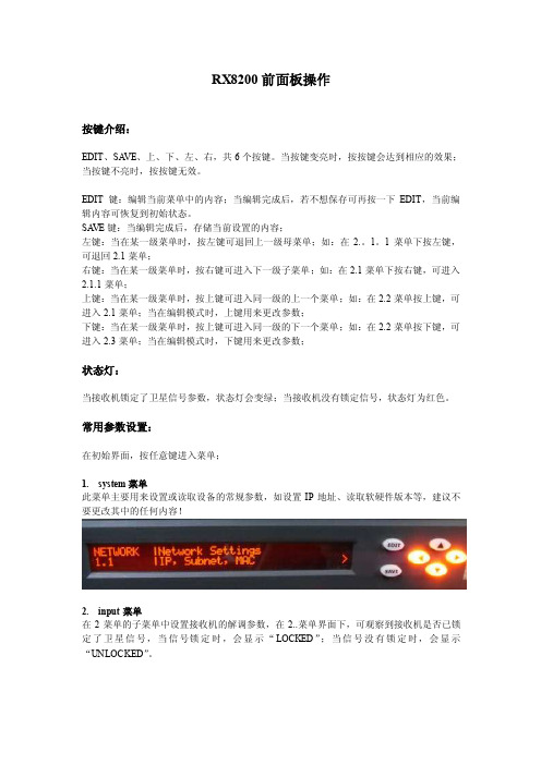
RX8200前面板操作按键介绍:EDIT、SA VE、上、下、左、右,共6个按键。
当按键变亮时,按按键会达到相应的效果;当按键不亮时,按按键无效。
EDIT键:编辑当前菜单中的内容;当编辑完成后,若不想保存可再按一下EDIT,当前编辑内容可恢复到初始状态。
SA VE键:当编辑完成后,存储当前设置的内容;左键:当在某一级菜单时,按左键可退回上一级母菜单;如:在2.。
1。
1菜单下按左键,可退回2.1菜单;右键:当在某一级菜单时,按右键可进入下一级子菜单;如:在2.1菜单下按右键,可进入2.1.1菜单;上键:当在某一级菜单时,按上键可进入同一级的上一个菜单;如:在2.2菜单按上键,可进入2.1菜单;当在编辑模式时,上键用来更改参数;下键:当在某一级菜单时,按上键可进入同一级的下一个菜单;如:在2.2菜单按下键,可进入2.3菜单;当在编辑模式时,下键用来更改参数;状态灯:当接收机锁定了卫星信号参数,状态灯会变绿;当接收机没有锁定信号,状态灯为红色。
常用参数设置:在初始界面,按任意键进入菜单;1.system菜单此菜单主要用来设置或读取设备的常规参数,如设置IP地址、读取软硬件版本等,建议不要更改其中的任何内容!2.input菜单在2菜单的子菜单中设置接收机的解调参数,在2..菜单界面下,可观察到接收机是否已锁定了卫星信号,当信号锁定时,会显示“LOCKED”;当信号没有锁定时,会显示“UNLOCKED”。
2.2 SELECT SA TELLITE INPUT(选择射频输入源)按EDIT和上下键,选择接收机的射频输入源,一般放在输入1。
2.2.1 STA TUS(状态)在此菜单按右键可进入2.2.1.x观察当前选择信号源的信噪比、信号强度、误码率等参数,这些参数只能读取不能修改。
2.2.2 CONFIGURE INPUT 1(设置输入1的参数)进入2.2.2的子菜单2.2.2.x可设置输入源1的解调参数,相应的进入2.2.3可设置输入源2的参数,进入2.2.4可设置输入源3的参数,进入2.2.5可设置输入源4的参数。
8200系列网络视频解码器 快速使用指南

8200系列网络视频解码器快速使用指南8200系 列 网 络 视 频 解 码 器 (Network Video Sever)快 速 使 用 指 南(V1.0)第 1 页 共 32 页8200系列网络视频解码器快速使用指南注明:本手册可能在某些技术细节方面描述不够准确或存在印刷错误,假如您在使用过程中按照快速使用指南无法解决问题时,请致电我公司客服部垂询相关操作方法。
本手册的内容将做不定期的更新,恕不另行通知。
第 2 页 共 32 页8200系列网络视频解码器快速使用指南目 录1.功能简介 (4)2.外观与说明 (5)3.解码器的连接 (6)4. 软件的基本操作 (7)4.1遥控器控制解码器 (7)4.1.1通过遥控器操作叠加菜单 (8)4.1.2主菜单 (9)4.2通过软件设置解码器 (11)4.2.1解码器参数设置 (15)4.2.2解码器通道设置 (17)4.2.3报警参数设置 (18)4.2.4音频、对讲 (21)4.2.5轮巡设置 (22)4.2.6云台控制及工具 (24)4.2.7工具 (25)4.2.8使用软件IMagineWordlDMatrix升级 (28)5.常见问题解答 (31)附录球型摄像机键盘的使用 (32)第 3 页 共 32 页8200系列网络视频解码器快速使用指南1.功能简介支持1路D1解码,用户可以根据实际使用情况监视;支持485接口的键盘的使用,通过该接口,用户可以控制GUI菜单及连接视频服务器端的云台功能;支持H.264视频解码,支持D1、Half-D1、CIF分辨率;支持音频输入输出,音频支持G711U、G722解码,对讲功能采用G722编码;支持解码器管理软件、遥控器及键盘控制设备。
第 4 页 共 32 页8200系列网络视频解码器快速使用指南第 5 页 共 32 页2.外观与说明经济型H.264网络视频解码器接口说明:【DC12V】:电源插口,与配套DC12V/ 2.0A 电源相连。
AOR AR8200 手持式收音机说明书 (2)

AR8200 Mk3 hand portable radio receiver ADDENDUM (paperwork V1.0)Due to continuous development of our products, the AR8200 has evolved into the Mk2 and Mk3 versions. As a result, operation differs from the original AR8200 in a few areas, please note the following changes to the AR8200 operating manual:1 The front ‘ten-key’ keypad has been rearranged in line with customer requests placing the ‘0’ zero key underneath the‘8’ eight key, as is standard practice with push button telephones. On page 9 section 1-5-1 of the English language operatingmanual, the graphic should now look like (the revised keypad has been used on the Mk3 and Mk2 versions):2 The Mk3 and Mk2 versions feature a built-in TCXO (Temperature Controlled Crystal Oscillator) in place of the reference crystal. This ensures the best levels of frequency stability and minimum spurii.3 In place of the previous rubber covered aerial, a telescopic whip on a swivel base is supplied (Mk3 and Mk2 versions).The whip provides the very best performance, especially on the VHF bands with the ability to adjust the length of the telescopic whip aerial to ‘peak’ received signal strength (the higher the frequency, the shorter the aerial). An alternative flexible smaller whip aerial is available as an option where durability and smaller size is important. Please refer to page 7 section 1-4 of the English language operating manual, line two of the table should now read “telescopic whip aerial”.4 The relationship between level squelch and signal meter has been revised. This affects VFO SEARCH LEVEL SQUELCH (page 47 section 4-4-3 of the English language operating manual), SCAN LEVEL SQUELCH (page 68 section 7-8-2 of the English language operating manual) and PROGRAM SEARCH LEVEL SQUELCH (page 84 section 8-7-2 of the English language operating manual).In each case, the following table replaces that previously employed:1 2 3 4 5 6 7 8 9 10 11 12 13 14Mk2 8 13 18 24 29 35 39 44 50 55 58 62 71 77Mk3 7 15 18 24 28 31 42 50 59 64 72 80 85 89As a result, the typical level at which the “«” legend will be extinguished has changed.5 The batteries supplied with the AR8200 have been changed. To ensure that a completely full charge is established, please assume the full charge time as follows, this replaces the reference given on page 19 section 1-6-4 of the English language operating manual.AR8200NiCads, 700mAhr12 hour chargeMk2NiCads, 1000mAhr14 hour chargeMk3NiMH, 1500mAhr22 hour charge SEE OVER >>>®AOR LTD, 2-6-4 Misuji, Taito-Ku, Tokyo 111-0055, Japan Tel: +81 3 3865 1695 Fax: +81 3 3865 1697e-mail:*****************:The AR8200 receiver employs standard ‘AA’ size batteries, so a range of different types can be used (NiCad, NiMH, alkaline etc). For this reason, the charging circuit cannot be optimised for any one specific type. It is most important that you do not over-charge the batteries and do not keep topping them up without first running them down. If the batteries are flat, do not attempt to ‘charge and operate’ the radio for the first hour of charging, this would lead to an increase in internal heat generated by the AR8200. Do not connect an external power supply, mobile power lead or charger if dry / alkaline batteries are fitted.In order to provide the optimum level of charge and life-span from the MiMH batteries (Nickel Metal Hydride) supplied with the Mk3, use of a specialist dedicated external battery charger is recommended, they are readily available from electrical suppliers. The AR8200 is not designed to charge rechargeable alkaline batteries.6 The design of the battery compartment and compartment cover has been revised to assist the easy replacement of batteries (Mk3 and Mk2), refer to page 16 section 1-6-1 of the English language operating manual. The cabinet colour of the AR8200 was green, the Mk3 and Mk2 cabinet is black.7 The operation of LCD/keypad illumination has been revised in the Mk3 version, refer to page 106 section 14-2 of the English language operating manual. When operating from internal batteries with AUTO LAMP selected, the illumination will activate for a few seconds when the squelch first opens. This is very useful for identifying transmission at night-time without using up excessive power from the batteries.8 The frequency coverage of the Mk3 version has been extended to 3GHz, the specified range is now 530kHz to 3GHz with actual minimum frequency input of 100kHz.9 Refer to the following specification for the Mk3 version which replaces that printed on page 140 of the English language operating manual:Frequency Range:530 kHz to 3000 MHz (3GHz)** Cell blocked in the USA for FCC rulesReceive Modes:WFM, NFM, SFM, WAM, AM, NAM, USB, LSB, CWSensitivity:500 kHz ~ 1.9 MHz AM: 3.5 µV (10dB S/N)1.9 MHz ~ 30 MHz AM:2.5 µV (10dB S/N)30 MHz ~ 470 MHz AM: 1.5 µV (10dB S/N)NFM: 0.85 µV (12dB SINAD)WFM: 1.5 µV (12dB SINAD)470 MHz ~ 1040 MHz NFM: 0.9 µV (12dB SINAD)1040MHz ~ 2040 MHz NFM: 9.0 µV (12dB SINAD)2040 MHz ~ 3000 MHz NFM: 25 µV (12dB SINAD)Selectivity:SSB/NAM3kHz (-6dB) / 9kHz (-40dB)AM/SFM9kHz (-6dB) / 20kHz (-40dB)WAM/NFM12kHz (-6dB) / 25kHz (-40dB)WFM150kHz (-3dB) / 360kHz (-20dB)Aerial input:BNC nominal 50 OHMAudio output:120mW (8 OHM) THD 10%Input voltage:9 ~ 16V DCPower Consumption:190mA (nominal)Operating temperature:-5°C to +50°CDimensions:61(W) x 143(H) x 39(D) mm approx excluding projectionsWeight:340 g approx including batteries and aerialSpecifications subject to change without notice due to continuous development of the receiver. E&OE.。
motorola中继台xirr8200设备参数
设备参数:1、XIRR8200专业无线对讲机常规通讯系统是无线通讯领域唯一尚未实现数字化的系统。
摩托罗拉在全球引领无线对讲机系统数字化进程。
XiR R8200数字中继台作为摩托罗拉首款数字中继台,帮您实现有限的模拟技术无法逾越的无限的数字技术功能,为您带来无限的使用价值。
XiR R8200中转台是MOTOROLA公司生产的一款高性能、高可靠性的产品,采用了先进的电路技术和模块结构技术,提供了一个全频段覆盖的高性能,高可靠,稳定的无线收发功能。
设备特点TDMA(时分多址) 2时隙工作一个数字中继台相当于2个模拟中继台。
TDMA(时分多址) 2时隙工作节省了频率资源一对频率相当于模拟中继台两对频率具有网络接口和USB接口支持第三方软件供应商开发调度软件实现数据/短信/GPS等应用具有网络接口支持最多15个中继台的IP互联,实现:(1)无线信号的大区域覆盖;(2)跨城市/跨国家的基站互联支持双机热备份:当主机出现故障时自动切换到备用机工作支持远程诊断和控制软件RDAC,可以实现中继台远程监控支持第三方内置双工器支持IP互联利用互联网可以最多互联15个数字中继台,可以实现无线信号的大区域覆盖,以及跨城市、跨国家的基站互联。
支持漫游XIRR8200数字中继台支持漫游功能。
设置为漫游的数字对讲机当接收到的数字中继台的信号低于设定值时,会自动搜索更强的中继台信号,自动切换并锁定。
用户无需关注信道,尽享跨区通讯的便利。
远程诊断和控制软件RDAC*系统管理员可以使用RDAC软件远程诊断、控制和管理数字中继台。
实现功能:中继台状态诊断有效/失效模拟/数字联网/本地转发发射功率(高/低)可用信道信号场强IP地址和UDP端口中继台报警接收机故障报警发射机故障报警温度过热报警电源故障报警主风扇故障报警中继台控制中继器打开/关闭切换信道切换发射功率(高/低)重启中继台RDAC远程监控管理界面图可以根据客户需求配置技术参数一般规格-30C +60C 接收机发射机。
珠江灯光8200说明书

XPar 348PR-8200注意:本说明书包含如何安全地进行安装以及使用的重要信息,请仔细阅读后按要求进行安装和操作,同时请将此说明书妥善保存,以备不时之需。
珠江灯光音响实业有限公司PR LIGHTING LTD.目录安全警告信息 3灯具结构及安装 4控制信号与电源的联接 4DMX回路插 5灯具功能设置 5灯具DMX起始地址设置 6操作菜单7DMX通道表9操作面板LED数码管显示信息说明 12 维护保养12一般故障检修12主要技术参数13电路接线图15零部件订购代码16本产品在出厂时,性能完好,包装完整。
所有使用者应严格遵守本说明书所陈述的警告事项和操作说明,任何因误用而导致的损坏不在本公司保证之内,对忽视操作手册而导致的故障和问题亦不在经销商负责的范围内。
本手册如有技术改动,恕不另行通知。
随机附件以下随机附件已随灯具一起包装,请注意检查核对:名称数量单位备注遮光器 1 个聚光筒 1 个选购件保险绳 1 条本说明书 1 本安全警告信息收到灯具后,请拆封检查是否有因运输而导致的损坏。
如出现运输而导致的损坏,请不要使用此灯具,并尽速与经销商或制造商联系。
本产品适用于室内外,其防护等级为IP67。
请不要将灯具直接安装在普通可燃物质表面上。
有资格的专业人员方可进行灯具的安装、操作和维修,并保证严格按本操作说明书所述规程操作。
请勿将灯具直接投射在可燃物体上,灯具和被照射物体之间的距离请保持在5米以上。
5m不要直视灯具的光源(尤其对于癫痫病患者),以免对眼睛造成损伤!请不要打开灯具自行维修,也不要对灯具结构作任何修改。
进行电气部分连接的人员必须有相应的资格方可进行操作。
在安装前,请确认您所使用的电源电压和灯具所标识的电压相符。
应将每一台灯具正确接地,并按照相关的标准进行电气安装。
不要将本灯具连接到其他任何调光装置上。
当灯具悬挂于高处工作时,基于安全的原因,请将随灯具配备的保险绳穿过把手或相关部位进行辅助吊装,具体安装方法请参照本说明书相关部分。
- 1、下载文档前请自行甄别文档内容的完整性,平台不提供额外的编辑、内容补充、找答案等附加服务。
- 2、"仅部分预览"的文档,不可在线预览部分如存在完整性等问题,可反馈申请退款(可完整预览的文档不适用该条件!)。
- 3、如文档侵犯您的权益,请联系客服反馈,我们会尽快为您处理(人工客服工作时间:9:00-18:30)。
MOTOROLA、 M 格式商标均为美国专利商标局注册商标。所有的产品或服务的名字均由所有者拥有。 © 2007, 2008 摩托罗拉公司 。
i
安装要求符合射频 (RF) 能量辐射安全标准
注意!
本对讲机旨在用于某些职业 / 受控应用,在这些应用中使用者完全了解辐射的可能性,而且能够采取措施来控 制辐射并符合 FCC 的规定。本机没有授权用于普通大众、消费者或其他用途。 为确保符合射频能量安全标准:
产品安全和射频辐射说明 ..............................................................................................................................i 手册修订 .......................................................................................................................................................i 定购部件 .......................................................................................................................................................i 计算机软件版权 ............................................................................................................................................i 文档版权 .......................................................................................................................................................i 免责声明 .......................................................................................................................................................i 商标 ..............................................................................................................................................................i
相关出版物 .......................................................................................................v
保修与服务支持 ..............................................................................................vii
/governmentandenterprise......................................................................................................i
安装要求符合射频 (RF) 能量辐射安全标准.......................................................ii
插图目录 ...........................................................................................................v
手册修订
手册发行后所做的修改在 PMR (出版本手册修订)中予以说明。此 PMR 提供所有增加、修改和删除项目的完整替换页 面。如要获得 PMR,请访问:
/asiaonline
定购部件
有关如何获得更换部件的信息,请参见附录 A: 定购更换部件。有关部件编号的信息,请参见 XiR R8200 转发器基本维修手 册 (摩托罗拉备件号 6871458M01)。
1.2.1 工作温度范围 .................................................................................................................... 1-1 1.2.2 湿度................................................................................................................................... 1-1 1.2.3 空气质量 ........................................................................................................................... 1-1 1.3 设备通风 ........................................................................................................................................ 1-2 1.4 交流输入电源要求 .......................................................................................................................... 1-2 1.4.1 电路过载 ........................................................................................................................... 1-2 1.5 设备安装方法 ................................................................................................................................. 1-2 1.6 现场接地和防雷保护 ...................................................................................................................... 1-2 1.6.1 电气接地 ........................................................................................................................... 1-2 1.6.2 射频接地 ........................................................................................................................... 1-2 1.6.3 防雷接地 ........................................................................................................................... 1-3
第 2 章 机械安装 ......................................................................................... 2-1
2.1 拆包设备 ........................................................................................................................................ 2-1 2.2 将设备从装运装置中转移到机架或机柜内 ...................................................................................... 2-1
计算机软件版权
本手册所介绍的产品可能包括储存于半导体存储器或其它媒体中的有版权的电脑程序。美国和其它国家的法律承认并保护摩 托罗拉对拥有版权的计算机程序享有专有权,表示只有摩托罗拉公司才能够以任何形式复制具有版权的计算机程序。因此, 本手册所介绍的摩托罗拉产品所包含的任何有版权的摩托罗拉电脑程序,在未经摩托罗拉书面允许的情况下,不允许进行任 何形式的拷贝、修改、反向工程或分发。除此之外,购买这些产品将不被认为拥有直接或暗示的版权人之版权、专利或专利 使用的任何许可证授权,产品销售过程中法律运用所引起的普通非专有性免税许可证除外。
文档版权
未经摩托罗拉公司的书面许可,不得对此文档或文档中的任何部分进行复制或分发。未经摩托罗拉公司的书面许可,不得以 任何方式,包括电子的或机械的方式对本手册中的任何部分进行复制、分发或传送。
免责声明