Flexi Ultrasite 诺西设备指导资料LiPing
4中国移动网络设备维护手册-GSM基站-诺西(试行)

我们已经迈出了坚实的第一步,在后续落实过程中,还需要各省公司坚持“有 章必循、违章必究、务求实效”。当然,行之有效的操作维护手册必须有一个在 实践中检验,并不断加以完善的过程。基层公司是最好的实践者,热切希望各公 司在实践中继续对维护手册提出宝贵意见和建议,让我们共同为确保中国移动卓 越网络品质而不懈努力!
没有规则不成方圆。制度流程立,则诸事兴,制度流程破,则百事废。完善 的代维管理制度和流程是做好代维工作的基础。为此,集团公司组织编制和修订 了中国移动代维管理系列规章。《中国移动网络设备维护手册-GSM 基站-诺西》 由集团公司组织福建、江西公司编制,共享了设备维护的典型故障案例、例行维 护项目的操作指南、常用板卡的更换要求等。
1
8) 允许波动范围:-57VDC~-40VDC 9) 电源线无老化现象 异常处理 1) 如果直流电源异常,检查机房电源是否有告警,根据告警灯的含义和电
源设备的使用说明进行故障排障。 2) 如果直流电源线老化,请更换。 3) 如果接头松动,请在做好安全防范措施的前提下进行紧固。 注意事项: 检查直流部分时金属工具预先做好绝缘防护,拒绝短路情况发生,尤其是蓄电池 组。
绝缘胶布,不应将裸线及裸鼻柄露出。 3) 电源线采用整段的线料,不得在中间接头; 4) 电源线采用走线架敷设时,应整齐平直,看不出有明显起伏不平的现象
及锤痕。导线的固定方法是否符合要求。 5) BTS 直流电源线采用 35mm2 铜芯线,黑线为正极蓝线为负极,或者红线
Flexi Ultrasite 诺西设备指导资料LiPing

基站BTS运行流程
天线
TRX 射 频 单 元
接收分路单元
双工器单元
Duplexer
TX RX
main div LNA
Duplexer
TX RX
main div
splitter
LNA
splitter
Ultrasite GSM 基 站 结 构
电源单元 • DC (0-3) • AC (0-2) 基本操作 接 口 单 元(1) 传 输 单 元 (1-4) • FC E1/T1 • FXC E1 • FXC E1/T1 • FXC RRI • FXC STM-1 • FXC Bridge
BTS数据设置及硬件设置
进入数据设置
浏览传输告警
传输口启用与配置
BTS时隙的设置
BTS时隙交叉
软件测试单元
硬件配置单元
BTS基站TX连线设置
BTS基站RX连线设置
BTS分级接收设置
FLEXI BTS_诺西设备告警及含义 70开头告警
• • • • • • • • • • • •
TRX 基 带 单 元 • GSM (0-6) • EDGE GSM (0-6)
TRX 射 频 单 元 • GSM (0-12) • EDGE GSM (0-12) • Booster (0-6) 接收分路单元 • 2-way (0-6) • 6-way (0-2)
合路器和双工器 • 双 工 器 (0-6) • 宽 带 合 路 器 (0-9) • RTC 合 路 器(0-2)
TRX/FU: CHECKSUM ERROR IN FU-CU LINK 在帧单元发给载波单元的数据中检测到数据传输校验和错误 TRX/FU: NO DATA FROM CU TO FU IN PRIMARY LINK 载波单元未向帧单元发送任何数据 TRX/FU: NO DATA FROM CU TO FU IN REDUNDANT/DIVERSITY LINK TRX/FU: GSM TIMESLOT UNATTAINABLE TRX/FU: MCLx2-FUCx LINK FAILURE TRX/FU: FAILURE IN BASE STATION INTERFACE 基站接口连接失败 来自MCLx2的入局时钟链路失败 TRX/FU: FUCx INTERNAL CLOCK FAILURE FUCx的内部GSM定时信号丢失 载波单元未向帧单元发送任何数据 GSM 时隙的语音和数据连接存在故障
诺西flei常用操作

Nokia Flexi BSC常用操作手册目录Flexi BSC MML菜单共有三级.............................. 错误!未定义书签。
主菜单 .............................................. 错误!未定义书签。
第二级菜单 .......................................... 错误!未定义书签。
第三级菜单 .......................................... 错误!未定义书签。
选择所需指令 ........................................ 错误!未定义书签。
2 .MML 命令句法...............................................错误!未定义书签。
3 .具体指令介绍...............................................错误!未定义书签。
ZWQ 软件包管理 ......................................... 错误!未定义书签。
ZWQB 校验软件包 ..................................... 错误!未定义书签。
ZWQO 显示软件包信息 ................................. 错误!未定义书签。
ZUS 工作状态和重启操作 ................................. 错误!未定义书签。
ZUSI 查询单元状态 ................................... 错误!未定义书签。
ZUSC 改变单元状态 ................................... 错误!未定义书签。
ZUST 改变单元信息 ................................... 错误!未定义书签。
诺希尔Xitanium LED驱动器数据手册说明书

XitaniumLED DriverDatasheetXitanium Dim 150W 1.05A 1-10V 230V YLED-based light sources are an excellent solution for outdoor environment. They are long-lasting and require low maintenance. However, to get the best out of the LEDs, these light sources require highly reliable and efficient LED Drivers. The new Philips Xitanium Fixed Output and Dimmable (1-10V) LED Outdoor Drivers are specifically designed to deliver reliable performance and protection while meeting the strict performance, approbation and application requirements.BenefitsReliability•Robust design; capable ofwithstanding harsh outdoorconditions.•Long lifetime and high survival rate.•Superior thermal managementsuitable for outdoor application.•Backed by 5 year warranty from a company you can trust. Affordable•Component integration in advanced IC enables cost effective design.•Proven robustness & reliability secure the lowest luminaire maintenanceover time.Easy to use•Extreme compact size. fitting with varied luminaires.•Easy to design-in based on the good thermal management and extra EMImargin Features•Proven robustness and reliableelectronic driver design.•Achieving highest efficiencies basedon advance technology.•Long lifetime; 50k hrs@Tc max.•Extreme compact size, fitting withvaried and critical luminaires.•Suitable for Class I isolated luminaires.•Authorized certificate: ENEC, CB, CEand CCC.Applications•Road and street lighting•Area and flood lighting•Tunnel lighting•High-bay lightingElectrical Input DataSpecification item Value Unit ConditionNominal Input Voltage220…240VacInput Voltage AC202…254Vac Performance rangeNominal Input Frequency50…60HzInput Frequency AC47…63Hz Maximum permissible rangeNominal Input Current0.76…0.69A220V…240V at full loadMaximum Input Current0.83A At202VNominal Input Power165W At 230V at full loadPower Factor≥0.95At 230V at full loadTotal Harmonic Distortion≤10%At 230V at full loadEfficiency92%At 230V at full loadElectrical Output DataSpecification item Value Unit ConditionRegulation Method Constant CurrentOutput Voltage62…142VdcOutput Voltage Max220Vdc Peak voltage at open circuitOutput Current1050…105mA Performance rangeOutput Current Tolerance±5%At max. output currentOutput Current Ripple LF5%Ripple = peak / average, at<1kHzOutput Power150W At full loadGalvanic Isolation Yes Basic; 2U+1000VElectrical Data Control InputSpecification item Value Unit ConditionControl Method1-10VDigital Interface N/A According 2.0 specificationsMains Control N/A Can be configured via MultiOneTime-based Integrated Control N/A Can be configured via MultiOne Dimming Range10-100%Wiring & ConnectionsSpecification item Value Unit ConditionInput Wire Size0.75mm²2-wire18AWG; 600V/105C rating or higher Output Wire Size0.75mm²2-wire 18AWG; 600V/105C rating or higher Input& Output Wire Length270 ±30mm Out of enclosureControl Wire Size N/A mm N/AControl Wire Length N/A mm N/ACE IsolationBasic Isolation: 2U+1000 V Input Wires Output Wires ChassisInput Wires N/A Basic BasicOutput Wires Basic N/A BasicChassis Basic Basic N/AOperational Temperature and HumiditySpecification item Value Unit ConditionAmbient Temperature-40…+55°CTcase Maximum80°C Measured at Tc-pointTcase Life70°C Measured at Tc-pointTcase Cut-Off85°C Power to LEDs is reducedStorage Temperature and HumiditySpecification item Value Unit ConditionAmbient Temperature-40…+55°CLifetimeSpecification item Value Unit ConditionLifetime100,000Hours At Tcase Life; Survival rate = 90% Programmable FeaturesSpecification item Value Remark ConditionAdjustable Output Current (AOC)N/A Default Output Current = xxx mA See Design-In GuideLED Module Temperature Derating(MTP)N/AConstant Lumen Output (CLO)N/ADC Emergency Dimming (DCEmDIM)N/ACorridor Mode N/AEnergy Metering N/ADiagnostics N/AFeaturesSpecification item Value Remark ConditionOpen Circuit Protection YesShort Circuit Protection Yes Automatic RecoveryOver Power Protection Yes Automatic RecoveryHot Wiring N/ASuitable for fixtures with Protection Class Class ICertificates and StandardsSpecification item ValueApproval Marks CE / CCC / ENEC/ CBIngress Protection Rating NAInrush CurrentSpecification item Value Unit ConditionInrush Current Ipeak46A At 230VacInrush Current Twidth440µs At 230Vac, measured at 50% Ipeak Drivers per MCB 16A Type B≤11pcsEarth Leakage CurrentSpecification item Value Unit ConditionTypical Leakage Current≤0.7mApk Meets IEC60598; LED module not included Surge CapabilitySpecification item Value Unit ConditionMains Surge Capability Differential Mode4KV L-N,2OhmMains Surge Capability Common Mode4KV L/N-GND,2OhmDimensionsSpecification item Value Unit ConditionLength overall168mmWidth overall60mmHeight overall38mmMounting Holes Distance153mmMounting Holes Width43mmMounting Holes Size5mm For M4 with max head diameter of 10mm Weight586gDimensions(in mm unless, otherwise specified)Logistical DataSpecification item ValueProduct Name Xitanium Dim 150W 1.05A 1-10V 230V Y Logistics Code 12NC9290 014 01780Pieces per Box12Operating windowEfficiency (Tcase = 70°C)GraphsPower Factor (Tcase = 70°C)8081828384858687888990919293946080100120140160180200220E f f i c i e n c yOutput Voltage202Vac230Vac 254VacEfficiency VS output voltage0.80.820.840.860.880.90.920.940.960.981406080100120140160P FOutput PowerPower Factor VS Output PowerTotal Harmonic Distortion (Tcase = 70°C)Output Current vs TcaseLifetime vs Tcase•Failure rate information based upon MTTF modeling: 90% survival at end of life @ Tcase <=80°C•Failure rate information based upon field call rate data: <0.01% per 1K hour @ Tcase <=80°C©2015 Koninklijke Philips Electronics N.Y.All rights reserved. Reproduction in whole or in part is prohibited without the prior written consent of the copyright owner. The informationpresented in this document does not form part of any quotation or contract, is believed to be accurate and reliable and may be changed without notice. No liability will be accepted by the publisher for any consequence of its use. Publication thereof does not convey nor imply any license under patent-or other industrial or intellectual property rights. Data subject to change.Date of release: April 30, 20151-10V dimming Curve1-10V dimming Curve。
诺西Flexi设备无线参数手册

诺西Flexi设备无线参数手册Flexi无线网络参数手册(v1.0)前言随着全省Flexi交流工程的展开,Flexi的优化与维护任务曾经提上日程。
由于Flexi在全省属于初次运用,在网优网规参数的运用上仍处于初级阶段。
为了加深对网优参数的了解和认知,让大家快速接受并运用Flexi各类优化参数,特编写本参数手册。
本手册对目前接触的Flexi参数停止了初步的解释,由于作者水平有限,望全省的优化人员依据实践运用多提珍贵意见,我们共同完成后继完善,共同制定Flexi参数优化战略。
目录Flexi无线网络参数手册(v1.0) (1)一、计时器〔Timer〕 (16)1、T4 (16)2、T7 (17)3、T8 (18)4、T10 (20)5、T13 (21)6、T17 (22)7、T18 (23)8、T3101 (24)9、T3103 (25)10、T3105_d (27)11、T3105_f (28)12、T3107 (29)13、T3109 (31)14、T3111 (32)15、T3121 (34)16、T3122 (35)17、T3168 (36)18、T3192 (36)19、T9101 (37)20、T9103 (38)21、T9104 (38)22、T9105 (39)23、T9108 (40)24、T9113 (41)二、设置BSC信息相关参数 (43)1、C-NUM (43)2、BSC_NAME (43)3、BSC_TYPE (43)4、IDLE_ET (43)5、BSC_LACATION (43)6、BCSU_NUM (43)7、BCF_NUM (43)8、SEG_NUM (43)9、TRX_NUM (44)10、NPC (44)11、GMAC/GMIC〔gsmMacrocellThreshold/gsmMicrocellThreshold〕 (44)12、DMAC/DMIC〔dcsMacrocellThreshold/dcsMicrocellThreshold〕 (44)13、DISB〔msDistanceBehaviour〕 (45)14、EPF、ERF、EOF、EEF (45)15、HRI(TCH in handover) (45)16、HRL/HRU(lower/upper limit for FR TCH resources) (45)17、AUT(AMH upper load threshold) (46)18、ALT(AMH lower load threshold) (46)19、AML(AMH max load of target cell) (46)20、CSD〔free TSL for CS downgrade〕 (46)21、 CSU〔Free TSLs For CS Upgrade〕 (47)22、TGT〔TRHO Guard Time〕 (47)23、HDL/HUL〔HO preference order interference DL/UL〕 (47)24、CLR〔load rate for channel search〕 (47)25、CTR〔CS TCH allocation RTSL0〕 (47)26、CTC〔CS TCH allocation calculation〕 (48)27、MINHTT〔minimum mean holding time for TCHs〕 (48)28、MAXHTT(maximum mean holding time for TCHs) (48)29、MAXHTS〔maximum mean holding time for SDCCHs〕 (48)30、TCHFR/SCHFR(Alarm Threshold For TCH/SDCCH Failure Rate) (49)31、CNGT/CNGS(Alarm Threshold For TCH/SDCCH Congestion) (49)32、CS(Alarm Threshold For Number Of Channel Seizures) (49)33、CSR(Alarm Threshold For Number Of Channel SeizureRequests) (49)34、PRDMHT(measurement period for TCH mean holding timesupervision) (49)35、PRDMHS(measurement period for SDCCH mean holding timesupervision) .. 5036、PRDCFR(measurement period for supervision of channel failure rate) . 5037、PRDCNG(measurement period for supervision of congestionin BTS) (50)38、HIFLVL(threshold for high TCH interference level) (50)39、HIFSHR(alarm threshold for the share of high TCH interference) (51)40、PRDHIF(measurement period for high TCH interference supervision) (51)41、PRDBNT(measurement period for supervision of BTS with no transactions) (51)42、SMBNT(starting moment for supervision of BTS) (51)43、EMBNT(ending moment for supervision of BTS) (51)44、GTUGT(GPRS territory update guard time) (52)45、BCSUL(BCSU load threshold) (52)46、LAPDL(LAPD load threshold) (52)47、MSSCF、MSSCS(upper limit of MS speed class 1、2) (52)48、ALFRT、ALHRT(alarm limit for full、half rate TCH availability) (53)49、ALSDC(alarm limit for SDCCH availability) (53)50、DINHO(disable internal HO) (53)51、DEXDR(disable external DR) (53)52、RXBAL(RX level balance) (53)53、RXANT(RX antenna supervision period) (54)54、ITCF(number of ignored transcoder failures) (54)55、VDLS(variable DL step size) (54)56、MNDL(maximum number of DL TBF) (54)57、MNUL(maximum number of UL TBF) (54)58、ISS(intra segment SDCCH HO guard) (55)59、PRE(pre-emption usage in handover) (55)60、SBCNF〔soft blocking C/N FR〕 (55)61、SBCNH〔Soft Blocking C/N HR〕 (55)62、RXTA〔RX level based TCH access〕 (55)63、DEC〔delay of HO and PC for emergency calls〕 (55)64、IHTA〔internal handover to external〕 (56)65、TTRC 〔TCH transaction count〕 (56)66、MTTR〔maximum TCH transaction rate〕 (56)67、DHP、DNP、DLP〔DL high、NORMAL、LOW priority SSS〕 (56)68、UP1、UP2、UP3、UP4〔UL priority 1、2、3、4 SSS〕 (56)69、BGSW1 、BGSW2 、BGSW3 〔Background traffic class scheduling weight forARP 1〕 (57)70、QCATR〔QC reallocation action trigger threshold〕 (57)71、QCATN〔QC NCCR action trigger threshold〕 (57)72、SPL〔supervision period length for EGPRS inactivity alarm〕 (57)73、IEPH〔events per hour for EGPRS inactivity alarm〕 (57)74、EGIC〔EGPRS inactivity criteria〕 (58)三、BCF设置相关参数 (58)1、BCF_ID (58)2、BCF_TYPE (58)3、LAPD_NAME (58)4、LAPD_BCSU (58)5、STATE (58)6、BBU (59)7、NTIM (59)8、BTIM (59)9、SENA (59)10、SM (59)11、T200F (60)12、T200S (60)四、SEG相关参数 (60)1、SEG_ID (60)2、LAC (60)3、CI (60)4、SEG_NAME (60)5、BSIC: (61)6、BNCC、BBCC (61)7、BAR〔cellBarred〕 (61)8、RE〔callReestablishmentAllowed〕 (61)9、EC〔emergencyCallRestricted〕 (61)10、PLMN〔plmn_permitted〕 (62)11、ACC〔NtAllowedAccessClasses〕 (62)12、DBC〔multiBandCell〕 (62)13、DR& DRM〔drInUse& drMethod〕 (62)14、MADR & MIDR〔maxTimeLimitDirectedRetry& minTime Limit Direced Retry〕 (63)15、GACC/GBAR/GRXP (63)16、HYS〔cellReselectHysteresis〕 (63)17、GHYS〔GPRSCellReselHysteresis〕 (64)18、RXP〔rxLevAccessMin〕 (64)19、TXP1〔MS Tx Pwr Max CCH1〕 (65)20、TXP2〔MS Tx Pwr Max CCH2〕 (65)21、GTXP1/GTXP2 (65)22、RLT〔radioLinkTimeout〕 (65)23、PO〔powerOffset〕 (66)24、DIRE〔:DirectGPRSaccessBts〕 (66)25、RRH(RaReselectHysteresis) (66)26、CHYS〔c31Hysteresis〕 (66)27、QUAL〔c32Qual〕 (66)28、RES〔reselection time〕 (67)29、PRC〔hcsPriorityClass〕 (67)30、HCS〔HCS threshold〕 (67)31、MQL〔maxQueueLength〕 (67)32、TLC〔timeLimitCall〕 (68)33、TLH〔timeLimitHandover〕 (68)34、QPU〔queuePriorityUsed〕 (68)35、QPC〔queueingPriorityCall〕 (68)36、QPH〔queueingPriorityHandover〕 (69)37、QPN〔queuePriorityNonUrgentHo〕 (69)38、MPU〔msPriorityUsedInQueueing〕 (69)39、AG〔noOfBlocksForAccessGrant〕 (69)40、MFR〔NOfMultiframesBetweenPaging〕 (70)41、PER〔timerPeriodicUpdateMS〕 (70)42、ATT〔allowIMSIAttachDetach〕 (71)43、AP〔interferenceAveragingProcess〕 (71)44、DTX〔dtxMode〕 (71)45、BMA〔btsMeasAver〕 (72)46、PMAX1〔maxMSTxPower1〕 (72)47、PMAX2〔maxMSTxPower2〕 (72)48、RET〔maxNumberRetransmission〕 (73)49、SLO〔numberOfSlotsSpreadTrans〕 (73)50、NY1〔maxNumberOfRepetitions〕 (73)51、CB〔smsCBUsed〕 (74)52、BLT〔btsLoadThreshold〕 (74)53、DMAX〔msMaxDistanceInCallSetup〕 (74)54、TRP〔trxPriorityInTCHAlloc〕 (74)55、CLC〔cell load for channel search〕 (75)56、TRIH〔tchrateIntraCellHo〕 (75)57、FRL〔lower limit for FR TCH resources〕 (75)58、FRU〔Upper Limit For FR TCH Resources〕 (75)59、NECI〔newEstabCausesSupport〕 (76)60、MBR〔multiBandCellReporting〕 (76)61、ESI〔earlySendingIndication〕 (76)62、AUT〔AMH upper load threshold〕 (76)63、ALT〔AMH lower load threshold〕 (76)64、AML〔AMH Max Load Of Target Cell〕 (77)65、TGT〔TRHO guard time〕 (77)66、PI〔cellReselectParamInd〕 (77)67、REO〔CellReselectOffset〕 (78)68、TEO〔temporaryOffset〕 (78)69、PET〔penaltyTime〕 (79)70、QUA〔cellBarQualify〕 (79)71、 QSRI〔threshold to search UTRAN cells〕 (79)72、QSRP〔GPRS threshold to search UTRAN cells〕 (79)73、FDD〔fdd and tdd cell reselect offset〕 (80)74、IDLE〔identification of BCCH frequency list〕 (80)75、ACT (80)76、MEAS〔measurement BCCH Allocation list〕 (81)77、GENA〔GPRSEnabled〕 (81)78、PSEI〔packet service entity identifier〕 (81)79、NSEI〔network service entity identifier〕 (81)80、RAC (81)81、BFG〔PrefBCCHfreqGPRS〕 (82)82、DLA〔DL adaption probability threshold〕 (82)83、ULA〔UL adaption probability threshold〕 (82)84、DLB〔PcuDLBlerCpNonHop〕 (82)85、ULB〔pcuULBlerCpNonHop〕 (83)86、DLBH〔pcuDLBlerCpHopping〕 (83)87、ULBH〔pcuULBlerCpHopping〕 (83)88、COD〔pcuCsNonHopping〕 (83)89、CODH〔pcuCsHopping〕 (83)90、MCA〔initial MCS for acknowledged mode〕 (84)91、MCU〔initial MCS for unacknowledged mode〕 (84)92、BLA〔maximum BLER in acknowledged mode〕 (84)93、BLU〔maximum BLER in unacknowledged mode〕 (84)94、MBG〔mean BEP offset GMSK〕 (84)95、MBP〔Mean BEP Offset 8PSK〕 (85)96、ELA〔EGPRS Link Adaptation Enabled〕 (85)97、QGDRT〔QC GPRS DL RLC ack throughput〕 (85)98、QGURT〔QC GPRS UL RLC ack throughput〕 (86)99、QEDRT〔QC EGPRS DL RLC ack throughput threshold〕 (86)100、QEURT〔QC EGPRS UL RLC ack throughput threshold〕 (86)五、BTS相关参数 (86)1、BTS_ID (86)2、HOP (87)3、BAND (87)4、MAL〔mobile allocation frequency list〕 (87)5、HSN1〔hopping sequence number 1〕 (87)6、HSN2 (87)7、GPU〔GPRSNonBCCHRxlevUpper〕 (88)8、GPL〔GPRSNonBCCHRxlevLower〕 (88)9、CNT〔cnThreshold〕 (88)10、BO0&BO1&BO2&BO3&BO4&BO5〔boundary〕 (88)11、PMIN〔minMSTxPower〕 (88)12、RDIV〔rx diversity〕 (89)13、NBL〔nonBCCHLayerOffset〕 (89)14、LSEG〔btsLoadInSeg〕 (89)15、DLN〔DL noise level〕 (89)16、ULN〔UL noise level〕 (90)17、MO〔maioOffset〕 (90)18、EGENA〔EGPRS enabled〕 (90)19、CDED〔DedicateGPRSCapacity〕 (90)20、CDEF〔DefaultGPRScapacity〕 (91)21、CMAX〔maxGPRScapacity〕 (91)22、DCSA〔DL coding scheme in acknowledged mode〕 (91)23、UCSA〔UL coding scheme in acknowledged mode〕 (91)24、DCSU〔DL coding scheme in unacknowledged mode〕 (92)25、UCSU〔UL coding scheme in unacknowledged mode〕 (92)26、ALA〔adaptive LA algorithm〕 (92)27、TFU〔BTS uplink throughput factor for CS1-CS4〕 (92)28、TFD〔BTS Downlink Throughput Factor For CS1-CS4〕 (93)29、TFUM1〔BTS uplink throughput factor for MCS1-MCS4〕 (93)30、TFUM〔BTS uplink throughput factor for MCS1-MCS9〕 (93)31、TFDM〔BTS downlink throughput factor for MCS1-MCS9〕 (93)32、EAW〔EGPRS inactivity alarm weekdays〕 (94)33、EAS〔EGPRS inactivity alarm start time〕 (94)34、EAE〔EGPRS inactivity alarm end time〕 (94)六、TRX相关参数 (94)1、HRS〔TRX half rate support〕 (94)2、PREF〔preferred BCCH TRX〕 (94)3、GTRX〔GPRSenabledTRX〕 (95)4、FREQ (95)5、TSC〔training sequence code〕 (95)6、FRT〔TRX frequency type〕 (95)7、LEV〔optimum RX level uplink〕 (95)8、DAL〔direct access level〕 (96)9、DAP〔dynamic abis pool ID〕 (96)10、LEVD〔optimum RX level downlink〕 (96)11、LAPD _NAME (96)七、切换的相关参数 (96)1、EIC〔enableIntraHoInterfUL〕 (96)2、EIH〔enableIntraHoInterfDL〕 (97)3、EPB〔enablePwrBudgetHandover〕 (97)4、EMS〔enableMSDistanceProcess〕 (97)5、ESD〔enableSDCCHHandover〕 (97)6、EUM〔enableUmbrellaHandover〕 (98)7、EFA〔enaFastAveCallSetup〕 (98)8、EFP〔enaFastAvePC〕 (98)9、EFH〔enaFastAveHO〕 (98)10、MIH〔minIntBetweenHoReq〕 (99)11、HPU〔HoPeriodUmbrella〕 (99)12、MIU〔minIntBetweenUnsuccHoAttempt〕 (99)13、HPP〔hoPeriodPBGT〕 (99)14、AWS〔averagingWindowSizeAdjCell〕 (99)15、NOZ〔numberOfZeroResults〕 (100)16、AAC〔allAdjacentCellsAveraged〕 (100)17、LDWS/LDW〔hoAveragingLevDL/ weighting〕 (100)18、LUWS/LUW〔hoAveragingLevUL/ weighting〕 (101)19、QDWS/QDW〔hoAveragingQualDL/ weighting〕 (101)20、QUWS/QUW〔hoAveragingQualUL/ weighting〕 (101)21、MSA〔msSpeedAveraging〕 (101)22、QDR/QDP/QDN〔hoThresholdsQualDL/PX/NX〕 (102)23、QUR/QUP/QUN〔hoThresholdsQualDL/PX/NX〕 (102)24、LDR/LDP/LDN〔hoThresholdsLevDL/PX/NX〕 (102)25、LUR/LUP/LUN〔hoThresholdsLevUL/PX/NX〕 (103)26、RPD〔HOThresholdsRapidLevUl〕 (103)27、ERFD〔enable enhanced rapid field drop〕 (103)28、ERT/ERP/ERN (103)29、ERMW〔deep dropping EDGE monitoring window〕 (103)30、ERAW〔modified averaging window〕 (104)31、ERZ〔modified number of zero results〕 (104)32、ERD〔enhanced rapid field drop duration〕 (104)33、IDR/IDP/IDN (104)34、IUR/IUP/IUN (105)35、MSWS〔msDistanceAveragingParam〕 (105)36、MSR/MSP/MSN (105)37、C/I (105)38、L1/ L2/ L3/ L4/ L5/ L6 (106)39、P1/ P2/ P3/P4/ P5/ P6/P7 (106)40、METH〔superReuseEstMethod〕 (106)41、MIO〔minIntUnsuccIuoHo〕 (106)42、MIR〔minIntIuoHoReqBQ〕 (106)43、CGR/CGP/CGN (107)44、CBR/ CBP/ CBN (107)45、LSL〔lowerSpeedLimit〕 (107)46、USL〔upperSpeedLimit〕 (107)47、STP/STN〔msSpeedThresholdPx/ msSpeedThresholdNx〕 (107)48、SDS〔msSpeedDetectionState〕 (108)49、ATPM〔AMH TRHO pbgt margin〕 (108)50、ATCM〔AMH traffic control MCN〕 (108)八、POC相关参数解释 (108)1、PENA〔powerCtrlEnabled〕 (108)2、INT〔powerControlInterval〕 (109)3、PMIN〔bsTxPwrMin〕 (109)4、PMAX〔bsTxPwrMax〕 (109)5、INC〔powerIncrStepsize〕 (109)6、RED〔powerRedStepsize〕 (109)7、PD0〔pwrDecrLimitBand0〕 (110)8、PD1〔pwrDecrLimitBand1〕 (110)9、PD2〔pwrDecrLimitBand2〕 (110)10、PDF〔pwrDecrQualFactor〕 (110)11、AENA〔enableALA〕 (110)12、AMIN〔minIntBetweenALA〕 (111)13、ALIM〔powerLimitALA〕 (111)14、LDS/LDW〔pcAveragingLevDL/ weighting〕 (111)15、LUS/LUW〔pcAveragingLevUL/ weighting〕 (111)16、QDS/QDW (112)17、QUS/QUW (112)18、UDR(QUA)/UDP(QUA)/UDN(QUA) (pcUpperThresholdsQualDL/PX/NX) (112)19、UUR(QUA)/UUP(QUA)/UUN(QUA) (112)20、LDR(QUA)/LDP(QUA)/LDN(QUA) (113)21、LUR(QUA)/LUP(QUA)/LUN(QUA) (113)22、LQR/ LQP/ LQN (113)23、UDR/UDP/UDN (113)24、UUR/UUP/UUN (113)25、LDR/ LDP/ LDN (114)26、LUR/LUP/LUN (114)27、IFP (114)28、TFP (114)29、ALPHA (115)30、GAMMA (115)31、BEP (115)九、GSM-ADJC相关参数 (115)1、NCC/BCC/FREQ (115)2、PMRG〔hoMarginPBGT〕 (115)3、LMRG〔hoMarginLev〕 (116)4、QMRG〔hoMarginQual〕 (116)5、MRGS〔enableHoMarginLevQual〕 (116)6、PRI〔hoPriorityLevel〕 (116)7、OF〔hoLoadFactor〕 (117)8、SL〔rxLevMinCell〕 (117)9、AUCL〔hoLevelUmbrella〕 (117)10、PMAX1〔MS TX pwr max gsm〕 (117)11、PMAX2〔MS TX pwr max gsm1x00〕 (117)12、SYNC〔syncronisedl〕 (118)13、TRHO〔trhoTargetLevel〕 (118)14、ACL〔adjCellLayer〕 (118)15、FMT〔fastMovingThreshold〕 (118)16、POPT〔msPwrOptLev〕 (118)17、CHAIN〔chainedAdjacentCell〕 (119)18、DRT〔drThreshold〕 (119)19、DADL〔〕 (119)20、AGENA〔GPRSEnabled〕 (119)21、GRXP〔GPRSRxLevAccessMin〕 (119)22、GTXP1〔gprsMsTxpwrMaxCCH〕 (120)23、GTXP2〔gprsMsTxPwrMaxCCH1x00〕 (120)24、PRC〔hcsPriorityClass〕 (120)25、HCS〔HCS signal level threshold〕 (120)26、GTEO〔GPRSTemporaryOffset〕 (120)27、GPET〔GPRSPenaltyTime〕 (121)28、RAC〔rac〕 (121)29、DTM〔DTM enabled〕 (121)一、计时器〔Timer〕1、T4说明:T4用来管理BSC发往MSC的RESET信息。
诺西基站典型故障处理

13
994938
BUS6/OUT – BUSIN
11
12
/ 2020/8/1
1
INSTALLATION GUIDE
• EDGE/BTS 8+8+8 WBC 4:1
2
Power Cables
3
4
NUMBER
CABLE
FROM – TO
1
994940 PWR – PWR 1
5
2
994940 PWR – PWR 2
are incorrectly configured
告警说明: 1、风扇告警:FLEXI EDGE基站设备的风扇告警主要有两
种情况,其一是有异物堵住风扇而触发告警,其二是风扇坏了;到目前 为止还没有发现因载频问题而触发风扇告警的情况。
一、7601风扇和电源线故障
2、电源连线告警:当FLEXI EDGE基站的配置小于等于12(小于等于6 块物理载频)时,只需一个系统模块(ESMA),此时 载频的BUS线和电源线都接于ESMA上,顺序依次是从左 到右为1、2、3、4、5、6。 而当FLEXI EDGE基站的配置大于12(即大于6块物 理载频)时,除需一个系统模块(ESMA)外,还需要一个 系统扩展模块(ESEA),此时载频BUS线全部接在ESEA上, 而载频的电源线则需要接在ESEA和ESMA上,且接于ESEA的 顺序从左到右依次是是1、2、3、4、5、6,接于ESMA的顺 序从左到右依次则是10、11、12、7、8、9。 如一个S8/8/8的配置,其连线如下图所示:
处理过程:1、先7745告警信息:01 00 00 00 01 00 00 00 00 03 02 34d第一个两位二进制数: 如果是01表示在TCH上的掉话,02表示在SDCCH上的掉话;
诺西Flexi常用操纵
Nokia Flexi BSC常用操作手册v1.0目录1.1 Flexi BSC MML菜单共有三级 (8)1.1.1 主菜单 (8)1.1.2 第二级菜单 (9)1.1.3 第三级菜单 (11)1.1.4 选择所需指令 (12)2 .MML 命令句法 (13)3 .具体指令介绍 (14)3.1 ZWQ 软件包管理 (14)3.1.2 ZWQO 显示软件包信息 (16)3.2 ZUS 工作状态和重启操作 (17)3.2.1 ZUSI 查询单元状态 (17)3.2.2 ZUSC 改变单元状态 (19)3.2.3 ZUST 改变单元信息 (20)3.2.4 ZUSL 显示具有某种状态或信息的单元 (21)3.2.5 ZUSU 重启单元 (22)3.2.6 ZUSS 重启系统 (24)3.3 ZDR 同步单元处理 (25)3.3.1 ZDRI 查询同步单元 (25)3.4 ZWT 硬件设备管理 (26)3.4.1 ZWTI 查询硬件设备信息 (26)3.5 ZDC 网元时钟处理 (28)3.5.1 ZDCD 显示BSC的日期、时间和时区 (28)3.6 ZAB 锁闭告警处理 (29)3.6.1 ZABO显示锁闭告警 (29)3.7 ZAH 历史告警和当前告警查询 (29)3.7.1 ZAHO 显示当前告警 (29)3.8 ZNE 信令网络状态查询 (32)3.8.1 ZNET 查询信令网络状态 (32)3.8.2 ZNEL 查询信令链路状态 (33)3.9 ZNH SCCP子系统状态处理 (34)3.9.1 ZNHI 查询子系统状态 (34)3.10 ZNR 信令路由集数据处理 (35)3.10.1 ZNRI 查询信令点数据 (35)3.11 ZNS 信令链路集数据处理 (36)3.11.1 ZNSI 查询信令链路集数据 (36)3.12 ZNG SCCP状态处理 (37)3.12.1 ZNGI 查询SCCP状态 (37)3.13 ZCE 电路状态处理 (39)3.13.1 ZCEL 查询外部电路状态 (39)3.14 ZRC 电路组处理 (41)3.14.1 ZRCI 查询电路组 (41)3.15 ZWG 编码器配置 (45)3.15.1 ZWGO 查询TC-PCM 信息 (45)3.16 ZEE 基站控制器参数处理 (46)3.16.2 ZEEO 查询BSC的一组参数配置 (48)3.16.3 ZEEL 显示载频的无线信道信息 (49)3.17 ZEO 基站告警处理 (51)3.17.1 ZEOL 显示当前基站告警 (51)3.17.2 ZEOH 显示历史告警数据 (52)3.18 ZDS 初始速率接入D-channel数据管理 (53)3.18.1 ZDSB 查询LAPD配置数据 (53)3.18.2 ZDSB 查询BSC信令信道数据 (54)3.19 ZDT 初始速率接入D-channel状态处理 (55)3.19.1 ZDTI 查询LAPD状态 (55)3.19.2 ZDTC 改变信令工作状态 (57)3.20 ZOB SCCP广播状态处理 (58)3.20.1 ZOBI 查询SCCP信令点的广播状态 (58)3.21 ZEF 基站相关处理 (60)3.21.1 ZEFS 改变BCF管理状态 (60)3.21.2 ZEFR 重启基站 (60)3.22 ZEQ 基站参数管理 (61)3.22.1 ZEQS 改变BTS管理状态 (61)3.22.2 ZEQE 修改BTS或SEG识别参数 (62)3.22.3 ZEQF 修改小区接入参数 (64)3.22.4 ZEQJ 修改CCH配置参数 (66)3.22.5 ZEQO 显示BTS参数 (67)3.22.6 ZEQM 修改各种小区参数 (68)3.22.7 ZEQV 修改小区GPRS参数 (72)3.23 ZER TRX管理 (76)3.23.1 ZERS 改变TRX和信道的管理状态 (76)3.23.2 ZERM 修改TRX的配置参数 (77)3.23.3 ZERD 删除TRX (82)3.23.4 ZERO 显示TRX参数 (83)3.24 ZUB 单个小区测试管理 (84)3.24.1 ZUBS 载频循环测试 (84)3.25 ZEA 邻区管理 (86)3.25.1 ZEAO 查看邻区参数 (86)3.25.2 ZEAT 同频同BSIC邻区查询 (88)3.25.3 ZEAC 创建邻区 (88)3.25.4 ZEAD 删除邻区 (95)3.25.5 ZEAM 修改邻区参数 (96)3.26 ZEH 切换控制参数管理 (100)3.26.1 ZEHO 查看切换参数 (100)3.27 ZEU 功率控制参数管理 (101)3.27.1 ZEUO 查看功率等级和功控参数 (101)3.27.2 ZEUG 调整功率控制参数 (102)3.27.3 ZEUS 修改电平门限 (104)3.27.4 ZEUQ 修改质量门限 (106)3.28 ZES Abis接口配置 (109)3.28.1 ZESM 修改动态池对应的时隙 (109)3.28.2 ZESI 查看动态Abis池(DAP)占用的时隙信息 (110)3.29 ZAC 清除告警 (111)3.29.1 ZACA 清除告警 (111)3.30 BSC软件包备份 (112)3.31 BSC故障板件更换处理 (114)3.32 基站故障处理 (114)3.33 危险命令 (115)1 .Flexi BSC指令MML菜单体系诺基亚Flexi BSC采用DX200系统,用户需通过身份验证(username and password)才能进入MML(人机语言)系统。
微蜂窝G设备替换工程中兴设备使用原则V
微蜂窝G设备替换工程中兴设备使用原则VThe following text is amended on 12 November 2020.(1)新建BBU(本原则仅针对本期900M设备替换)1)BBU设计原则:①机房内原有诺西设备原有2G主设备本次不进行拆除,如新替换的设备没有位置,再拆除原有2G设备。
②新建BBU安装方式尽量靠近原有4G主设备安装位置,优先综合架,其次挂墙(整站领货已包含挂墙机框),最后考虑利旧诺西19英寸机柜;BBU高度为4U(BBU:3U+导风插箱:1U),上下各留1U散热空间。
③电源BBU已配置PMAC交流电源模块,需6A以上独立空开;BBU电源线3*。
④基带板配置单BBU最大支持9块基带板,考虑到后期扩容场景,综合考虑单BBU系统稳定性(机房散热等因素),本期工程每BBU 配置各种模式基带板总数不超过4块。
A:FDD基带板BPP1每块最大支持合并小区的数量为12个2T2R,每块基带板提供6路10G光口;本期工程每台BBU配置1块BPP1。
B:GSM基带板UBPG3每块UBPG3支持24个TRX资源;BBU最多支持3块UBPG3 (72TRX),建议不超过2块(48TRX);同一块基带板的24个TRX可合并成一个逻辑载频做超级小区配置,不能跨基带板做逻辑载频合并。
C:FS5B-光纤交换板UBPG3无光口,需与FS5B-光纤交换板同时使用;RRU直接连接到FS5B上(BPP1光口不用);建议FS5B最多插2块。
D:RRU配置和级联本期工程按照GSM最大支持O8。
注:RRU能力1FDD+1N+6GSM或者1FDD+8GSM(本期不考虑,考虑FDD,2级级联;不考虑FDD,4级级联)⑤时钟同步方式GPS优先合路,其次新增,最后1588v2;原BBU的 GPS使用4功分器时不考虑合路。
⑥BBU合并满足以上原则情况下,原诺西多个MCPA设备可以进行BBU 合并。
采用星型结构。
⑦BBU接传输方式中兴新装BBU的传输通过级联原有TDD的BBU实现,原BBU如为CC16板,更换为CCE1板。
2G诺西维护
PWR IN
Ant 6 Rx Ant 5 Rx Out EAC
Ant 5 Tx/Rx
Ant 4 Rx
Ant 3 Tx/Rx
Ant 2 Rx
Ant 1 Tx/Rx
Fan / RF OffUnit
Ant 3 Rx Out CLASS 1 LASER PRODUCT OPT 1
双工器 + 接收
2G设备介绍-MCPA
Flexi BTS_MCPA 主模块----系统模块(ESMB/ESMC)
Q1 FPA Optical RP3 01 Synch out Synch in EAC LMP
Power input 3 HU
PWR PWR PWR PWR PWR
Ground
Transmission PIU
Ant 1 Rx Out OPT 2 OPT 3
2G设备介绍-MCPA
下图为1个系统模块和2个RF模块,可藉此配置12+12+12的系统
2G设备介绍-MCPA
下图为配置2个RF模块1个小区时的接法,2个RF模块最大可做到 12+12+12的配置
PWR IN
Ant 6 Rx Ant 5 Rx Out EAC
LNA LNA
X
RX
Duplexer
TX RX main RX div
MCPA
RXMC
LNA LNA
RX
RP3光纤接口
谢 谢 谢谢
18载频3 扇区 射频模块
扇区1 (6 载频) 扇区2 (6 载频) 扇区3 (6 载频)
MCPA MCPA
MPE参数使用方法及E频点注意事项(诺西设备)
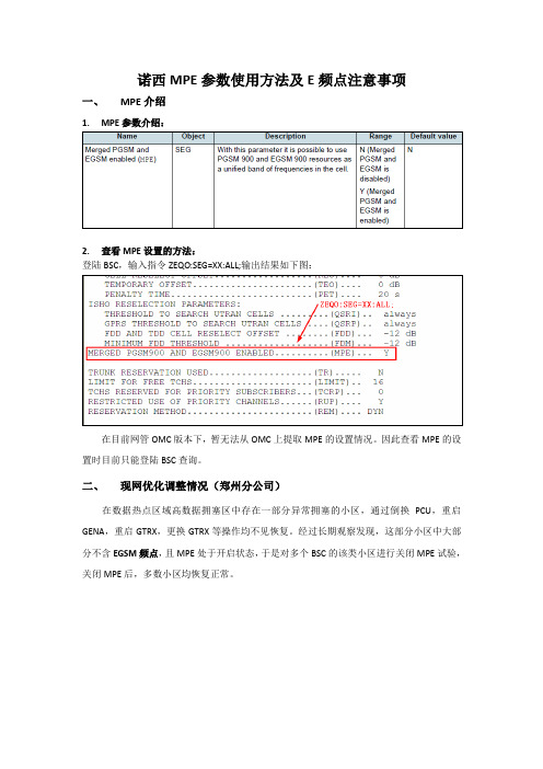
诺西MPE参数使用方法及E频点注意事项一、MPE介绍2.查看MPE设置的方法:登陆BSC,输入指令ZEQO:SEG=XX:ALL;输出结果如下图:在目前网管OMC版本下,暂无法从OMC上提取MPE的设置情况。
因此查看MPE的设置时目前只能登陆BSC查询。
二、现网优化调整情况(郑州分公司)在数据热点区域高数据拥塞区中存在一部分异常拥塞的小区,通过倒换PCU,重启GENA,重启GTRX,更换GTRX等操作均不见恢复。
经过长期观察发现,这部分小区中大部分不含EGSM频点,且MPE处于开启状态,于是对多个BSC的该类小区进行关闭MPE试验,关闭MPE后,多数小区均恢复正常。
3月2日14点关闭5个小区的MPE功能,下表是小区的BSC、PCU、BTS、BAND等信息:关闭MPE后小区的数据流量变化:关闭MPE后小区的硬拥塞变化:2.第二批关闭MPE小区的情况3月2日19点关闭5个小区的MPE功能,下表是小区的BSC、PCU、BTS、BAND等信息:关闭MPE后小区的数据流量变化:关闭MPE后小区的硬拥塞变化:3.第三批关闭MPE小区的情况3月4日10等信息:关闭MPE后小区的数据流量变化:关闭MPE后小区的硬拥塞变化:小结:针对存在异常拥塞的数据热点高数据拥塞小区,对于未使用EGSM 频点且MPE 处于开启状态的,则进行关闭MPE 操作,本月共计关闭MPE 的热点小区536个,其中MPE 关闭前统计2号至4号数据,拥塞小区为300个,关闭MPE 后统计26号至28号三天数据,得出仅166个小区仍存在拥塞情况,其余热点小区已经基本不存在异常超忙现象,效果明显,对网络整体超忙指标具有积极的改善作用。
三、总结:1.MPE参数使用方法:GSM900M小区:有E频点(与PGSM频点混用),则MPE应设为Y;无E频点,则MPE 应设为N。
DCS1800M小区:MPE应设为N。
2.E频点注意事项:1)E频点不要应用在BCCH载频上;2)建议GTRX不要开在有E频点的载频上,否则可能会出现(E)GPRS业务无法使用E频点的情况,详细情况如下附件。
FlexiBRITE24 illumination系列安装指南说明书
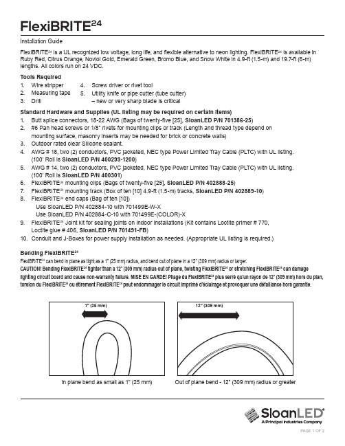
FlexiBRITE24 is a UL recognized low voltage, long life, and flexible alternative to neon lighting. FlexiBRITE24 is available in Ruby Red, Citrus Orange, Noviol Gold, Emerald Green, Bromo Blue, and Snow White in 4.9-ft (1.5-m) and 19.7-ft (6-m) lengths. All colors run on 24 VDC.Tools Required1. Wire stripper2. Measuring tape3. DrillStandard Hardware and Supplies (UL listing may be required on certain items)1. Butt splice connectors, 18-22 AWG (Bags of twenty-five [25], SloanLED P/N 701386-25)2. #6 Pan head screws or 1/8" rivets for mounting clips or track (Length and thread type depend onmounting surface, masonry inserts may be needed for brick or concrete walls)3. Outdoor rated clear Silicone sealant.4. AWG # 18, two (2) conductors, PVC jacketed, NEC type Power Limited Tray Cable (PLTC) with UL listing.(100' Roll is SloanLED P/N 400299-1200)5. AWG # 14, two (2) conductors, PVC jacketed, NEC type Power Limited Tray Cable (PLTC) with UL listing.(100' Roll is SloanLED P/N 400301)6. FlexiBRITE24 mounting clips (Bags of twenty-five [25], SloanLED P/N 402888-25)7. FlexiBRITE24 mounting track (Box of ten [10] 4.9-ft (1.5-m) tracks, SloanLED P/N 402889-10)8. FlexiBRITE24 end caps (Bag of ten [10])Use SloanLED P/N 402884-10 with 701499E-W-XUse SloanLED P/N 402884-C-10 with 701499E-(COLOR)-X9. FlexiBRITE24 Joint kit for sealing joints on indoor installations (Kit contains Loctite primer # 770,Loctite glue # 406, SloanLED P/N 701491-FB)10. Conduit and J-Boxes for power supply installation as needed. (Appropriate UL listing is required.)Bending FlexiBRITE24FlexiBRITE24 can bend in plane as tight as a 1" (25 mm) radius, and bend out of plane in a 12" (309 mm) radius or larger.CAUTION! Bending FlexiBRITE24 tighter than a 12" (309 mm) radius out of plane, twisting FlexiBRITE24 or stretching FlexiBRITE24 can damage lighting circuit board and cause non-warranty failure. MISE EN GARDE! Pliage du FlexiBRITE24 plus serré qu’un rayon de 12" (309 mm) hors du plan, torsion du FlexiBRITE24 ou étirement FlexiBRITE24 peut endommager le circuit imprimé d’éclairage et provoquer une défaillance hors garantie.In plane bend as small as 1" (25 mm)Out of plane bend - 12" (309 mm) radius or greater4. Screw driver or rivet tool5. Utility knife or pipe cutter (tube cutter)– new or very sharp blade is criticalCutting FlexiBRITE24FlexiBRITE24 can be cut to shorter lengths. All cut pieces can be used provided cut is made on cut line and eachsection has a set of wires for power hook up. Cut Marks are black lines that can be seen through one side of extrusion. FlexiBRITE24 has cut lines on 1.97" (50 mm) increments. Use a sharp blade to make a clean cut. All ends must be sealed. Wherever possible use 19.7-ft (6-m) lengths for longer runs, and 4.9-ft (1.5-m) lengths for shorter runs to minimize number of joints that have to be sealed.Connecting FlexiBRITE24When connecting FlexiBRITE24 pieces together ensure that polarity is correct by connecting Red-to-Red and Black-to-Black. NOTE: Hold wires finger tight when stripping. If wires are not held in place they may break free from FlexiBRITE24 extrusion. Both parallel and series connections of FlexiBRITE24 are allowable as long as maximum allowable total length is not exceeded.Trim open wiresAny wire loops that have been cut, but are not being used for an electrical connection must be trimmed flush with extrusion and covered with a bead of silicone.Mounting FlexiBRITE24FlexiBRITE24 can be mounted to any surface that will accommodate conventional fasteners.FlexiBRITE24 mounting track is recommended for straight runs of FlexiBRITE24. The mounting track comes in boxes of ten (10) 4.9-ft (1.5-m) pieces (SloanLED P/N 402889-10). For script letters and free form shapes use FlexiBRITE24 mounting clips (SloanLED P/N 402888-25 in bags of twenty-five [25]).Mounting track: Cut mounting track to required lengths and fasten to surface with #6 pan head screws.Make all electrical connections for FlexiBRITE24 using butt splice connectors and coat these connections with liquid electrical tape or silicone. When pressing FlexiBRITE24 into mounting track, a little soapy water on back of FlexiBRITE24 tubing will lubricate it and help it push in.Mounting clips: Place mounting clips wherever necessary to shape FlexiBRITE24 to desired contour. Fasten clips to mounting surface using #6 pan head screws or 1/8" rivets. For added security, a clear chain tie can be used with mounting clips to cinch FlexiBRITE24 into place (SloanLED P/N 701653-100, in bags of one hundred [100]).NOTE: Clear chain ties are not UV stable, thus for indoor use only.Sealing exposed ends (REQUIRED for outdoor applications)Apply end caps to all exposed ends. Any exposed ends without end caps will lead to failure of FlexiBRITE24.Sealing Exposed Ends - Required for Outdoor Applications7. Use UL Listed butt splices to complete electrical connection to next piece of FlexiBRITE 24 or power supply if needed. Seal connection with liquid electrical tape or silicone.8. Trim Open Wires: Any wire loops that have been cut, but are not being used for an electrical connection must be trimmed flush with extrusion and covered with a bead of silicone.6. Butt ends together and use mounting clips as needed to keep them lined up.3. FlexiBRITE 24 White only:Plastic insert (shipped with product) MUST be installed at field cut end prior to applyingend cap and silicone.2. Gather required tools, clear Dow Corning 737 silicone sealant or equivalent, and necessary end caps. Refer to Standard Hardware and Supplies(#8) on page 1.1. FlexiBRITE 24 cut marks are on side and bottom of extrusion. Cut marks are spaced every 1.97" (50 mm).Any cut section will light provided there arewires for power hook-up.extrusion, clean off silicone residue and allow to cure. NOTE: Silicone will take at least 24 hours to fully cure. It can cure in place on an installation as long as it is not disturbed while curing.4. Apply silicone to inside of end cap to be bonded. Ensure that enough is used to cover entire surface area of inside of end cap and at least half of its depth.Optional Joint Sealing - for Indoor Applications Onlysealed around entire perimeter.FlexiBRITE 24 or power supply if needed. Seal connection with liquid electrical tape or silicone.cause failures.7. Trim Open Wires: Any wire loops that have been cut, but are not being used for an electrical connection must be trimmed flush with extrusion and covered with a bead of silicone.1. FlexiBRITE 24 cut marks are on side and bottom of extrusion. Cut marks are spaced every 1.97" (50 mm) .Any cut section will light provided there are wires for power hook-up. 2. Coat face of both pieces to be bonded together with primer. Any area not primed, will not bond. Primer will dry in less than 15 seconds and is active for 1 hour (Joint kit: SloanLED P/N 701491-FB ).3. Apply a layer of glue to face of one piece of FlexiBRITE 24(Joint kit: SloanLED P/N 701491-FB ).Power Supply ConnectionConnect output on power supply to beginning of FlexiBRITE 24 leg. Connect red wire of power supply output to any available red wire on FlexiBRITE 24 leg and connect black wire of power supply output to any available black wire on FlexiBRITE 24 leg. SloanLED power supplies have Class 2 DC outputs. It is recommended that current be checked on each power supply output after loading is complete. Current drawn by each leg should not exceed current rating on power supply label. If measured current does exceed rated current, reduce length of FlexiBRITE 24 on that leg until current is below rated output.Routing Secondary WiresWhen wiring secondary outputs of power supply, all routing through walls must be sealed with outdoor rated caulk toprotect sign and building from water damage and cable from chafing. The PLTC used for power supply leads and jumpers can be routed through walls, inside and outside without conduit. It is recommended that all connections be enclosed in a UL listed junction box with strain relief.Extension of Power Supply LeadsIf a longer lead wire from power supply to FlexiBRITE 24 chain is needed, an extension can be used. The extension should be kept as short as possible (under 15 ft [4.6 m] for 18 AWG UL Listed PLTC or under 50 ft [15 m] for 14 AWG UL Listed PLTC).WARNING: CHECK POLARITYAfter all wire routing is complete and lighting modules are connected to power supply, RECHECK POLARITY OF ALL CONNECTIONS. They must be RED-TO-RED and BLACK-TO-BLACK throughout entire system. Reverse polarity connections may damage LEDs and void product warranty.NOTE: For power supply installation instructions check manual packaged with your power supply or check online at .24 VDC Power Supply Capacity ChartCapacities based on 90% of power supply output.NOTE: Refer to “SloanLED Power Supply Guide for Sign Products ” for appropriate 24 V power supply models.Scan QR code to download SloanLED Power Supply Guide for Sign Productshttps:///PowerSupplyGuideForSignProductsSloanLED Headquarters5725 Olivas Park Drive, Ventura, CA, USA888.747.4LED(888.747.4533)•*****************SloanLED Europe b.v.Argonstraat 110, 2718 SN Zoetermeer, NL +31881244900•*******************P/N 402958 2023-03-28Customer service and technical supportTroubleshooting:Entire Sign or leg withFlexiBRITE 24 does not light after complete installation.Check connection from power supply lead to FlexiBRITE 24 chain. Make sure polarity of connections made at power supply lead and at any jumper wire connection is correct. All connections should be RED-to-RED and BLACK-to-BLACK.Still does not light.Using a voltmeter check output voltage of power supply. Output voltage should be 24.0 VDC ± 0.5 VDC. If there is no output voltage, have a licensed electrician check input voltage. Make sure power supply is hooked up correctly and getting primary power. If power supply is hooked up correctly and getting primary power and there is still no output voltage, replace power supply with a new one.The beginning of a FlexiBRITE 24 leg lights, but entire leg does not light or lights intermittently.The primary cause of a portion of a FlexiBRITE 24 leg not lighting or lighting intermittently is a bad connection between length that lights and length that doesn’t light. Check this connection and ensure correct polarity.Small segment of a length of FlexiBRITE 24 does not light, but rest of length lights.FlexiBRITE 24 is designed so if one segment fails, it will not cause entire sign or leg to go out. If one segment is not lighting, but remainder of length of FlexiBRITE 24 is lighting, remove and replace segment, or replace length with a new one.UL Labeling:FlexiBRITE 24 is also a UL Recognized Sign Component under UL48 File #E215393.The most common way FlexiBRITE 24 is labeled for UL is for it to be used as a UL Recognized Sign Component. FlexiBRITE 24 is a UL Recognized Sign Component and Power Supplies provided by SloanLED are UL Recognized Sign Components. When they are properly installed in a sign by a UL sign shop, the shop can apply its UL label to the whole assembly.FlexiBRITE 24 Part #Description701499E-R-2019.7 ft (6 m) Ruby Red 701499E-R-5 4.9 ft (1.5 m) Ruby Red 701499E-O-2019.7 ft (6 m) Citrus Orange 701499E-O-5 4.9 ft (1.5 m) Citrus Orange 701499E-Y-2019.7 ft (6 m) Noviol Gold 701499E-Y-54.9 ft (1.5 m) Noviol GoldFlexiBRITE 24 Part #Description701499E-G-2019.7 ft (6 m) Emerald Green 701499E-G-5 4.9 ft (1.5 m) Emerald Green 701499E-B-2019.7 ft (6 m) Bromo Blue 701499E-B-5 4.9 ft (1.5 m) Bromo Blue 701499E-W-2019.7 ft (6 m) Snow White 701499E-W-54.9 ft (1.5 m) Snow WhiteE215393。
诺西Flexi设备硬件指导手册v1.0

中国移动诺基亚FLEXI设备硬件指导手册目录第一章 Flexi BSC硬件结构介绍 (3)一、Flexi BSC简介 (3)1.1 Flexi BSC特点 (3)1.2 Flexi BSC产品简介 (3)二、Flexi BSC模块介绍 (6)2.1 操作维护单元OMU (7)2.2标志和蜂窝管理单元MCMU (7)2.3 基站控制器信令单元BCSU (8)2.4 时钟单元CLS (8)2.5 时钟分发单元CLAB/CLAC (9)2.6 码型转换单元TCSM (9)2.7 总线单元MB/EMB (9)2.8 交换终端ET (10)2.9 其他单元和插板功能 (10)三、Flexi BSC的机框和插板单元 (11)3.1 SGC1C-A机框 (12)3.2 第三层机框内单元 (12)3.3 BC1C-B机框 (13)四、Flexi BSC的计算机单元 (14)4.1 MCMU中的主要插板 (14)4.2 BCSU中的主要插板 (17)4.3 OMU中的主要插板 (20)五、其他单元 (22)5.1 GSW2KB(Group Switch) (22)5.2 CLS(Clock unit) (23)六、硬件单元状态 (23)第二章 Flexi EDGE BTS基本结构 (25)一、体系结构 (25)1.1 主要模块 (26)1.2 其他模块 (30)1.3 Flexi GSM 系统扩展模块(ESEA) (32)1.4 Flexi GSM系统外部告警模块(FSEx) (32)第一章 Flexi BSC硬件结构介绍一、Flexi BSC简介1.1 Flexi BSC特点目前我省使用的BSC设备都是Flexi BSC(如图2.1),机架长宽深分别为:2000*900*600。
Flexi BSC 的主要特点为:1、支持最大18000爱尔兰语音业务容量;2、支持最多30720个数据业务信道;3、最大支持3000个载频;4、支持最大72万次的寻呼承载。
诺西BTS维护操作手册

《诺西基站维护操作手册》1 系统结构及重要硬件介绍1.1 前言本文档作为诺基亚西门子公司的GSM基站的操作维护的部分,对2G BTS做了详细的说明,系统地介绍了目前现网中2G基站的结构,功能。
重点地描述了现网中2G基站的操作维护部分。
1.2 硬件平台11.2.1系统框图及简介目前NSN的2代和3代基站基本已退出历史舞台,现网中主要是Ultrasite,是做为NSN的第四代基站。
主要结构图如下:1.2.2功能块介绍Ultrasite基站主要由机柜,公共单元,射频单元组成。
机柜主要有两种,一种是容量为12载频Ultrasite(左图),一种是容量为6载频MIDI Ultrasite(右图)。
1.2.3主要硬件板卡介绍公共单元的主要由如下硬件组成:BOIx:Base Operations and Interface Unit 操作管理接口单元VXxx:Transmission Units 传输单元BB2x:Baseband Units 基带单元PWSx:Power Supply Units 电源单元FAN:Cooling Fan units 风扇单元射频单元主要由如下硬件组成:TSxx:Transceiver RF Units 载频射频单元M2/6xA:Receiver Multicouplers 接收多路耦合器单元WCxA:Wide Band Combiner 宽带合路器单元DVxA:Dual Variable Gain Duplex Filter 双工滤波器单元RTC: Remote Tune Combiner 远程调谐合路单元FAN:Cooling Fan units 风扇单元RF Cable: 射频线1.3硬件平台21.3.1系统框图及简介Flexi EDGE BTS 作为现网中另一种2G 基站,一般称为NSN的五代站,有更高集成度,安装便捷,配臵灵活,节能等特点。
其结构图如下:1.3.2功能块介绍Flexi EDGE BTS 主要由系统模块和射频模块组成,可以安装在室内外,可以安装在多种环境下:Presentation / AuthorFlexi GSM 光纤拉远Alex / 08年04月23©Nokia Siemens Networks 美化安装内墙挂壁安装室内机柜或Ultrasite Cositing 室内叠放安装Flexi楼顶简易塔塔顶或塔底安装©Nokia Siemens NetworksPresentation / AuthorFlexi GSM 光纤拉远/Alex / 08年041.3.3主要硬件板卡介绍系统模块部分:ESMA:System Module 系统模块ESEA:System Extension Module 系统扩展模块FIxA: Transmission units 传输单元Bus Cable:数据线Power Cable:电源线射频模块部分:EXxA: Dual TRX Module 双载频单元ERxA: Dual Duplexer Module 双工滤波器单元ECxA: Remote Tune Combiner 远程调谐合路单元EWxA: Wideband Combiner Sub-Module 宽带合路器单元RF Cable: 射频线2 维护作业计划操作指导(按照维护规程要求内容)2.1 维护作业计划概述随着GSM网络的增大,基站的数量越来越大。
诺西FlxeiBSC常用操作手册

诺西BTS设备基维护知识测试题库

中国联通移动网网络及诺西BTS设备维护知识测试题库一、判断题1.诺西BS240/241最大配置3个(载频)机架,24个TRX。
(是)□2.诺西所有BTSplus基站可以提供GPRS业务及EDGE业务。
(是)□3.诺西BS24x/BS4x基站同一机架内只支持单频配置:GSM900或GSM1800。
(否)□4.对于诺西BS24x/BS4x基站的GSM900系统来讲,载频单元功率输出达50W。
(是)□5.对于诺西BS24x/BS4x基站的GSM1800系统来讲,载频单元功率输出达30W。
(否)□6.诺西BS24x/BS4x基站室内站工作温度范围:-5ºC...+55ºC;室外站工作温度范围:-45ºC...+50ºC。
(是)□7.诺西BS240/241和BS240XL机柜扩展:(最多)到24个TRX/站点,12个TRX/小区,6个小区/机架,6个小区/站点。
(否)□8.诺西BTSplus基站的COSA模块上有Flash-EPROM,可存储所有BTSE的软件。
(否)□9.诺西BS24x/BS4x基站的载频单元包含所有模拟和数字信号的处理单元(包括一个射频功率等级),支持一个GSM/EDGE载频(8个时隙)。
(是)□10.诺西BTSplus基站的载频单元和核心模块之间的通信主要通过双向串行线实现(CC-Link)。
(是)□11.诺西BTSplus基站的主要部件有核心模块(COBA/COSA)、面向载频的载频单元(CU)和合路设备(DUAMCO、FICOM和DIAMCO),所有非CU模块(例如DUAMCO)通过CC-Link总线向COBA报告告警。
(否)□12.诺西BTSplus基站的载频单元由下列单元组成:功率放大器及收发信单元PATRX、SIPRO和电源单元PSU构成。
(是)□13.如果BTSplus基站的双工放大多路耦合器DUAMCO的其中一个放大器出现故障时,DUAMCO的接收增益大约减少6dB。
- 1、下载文档前请自行甄别文档内容的完整性,平台不提供额外的编辑、内容补充、找答案等附加服务。
- 2、"仅部分预览"的文档,不可在线预览部分如存在完整性等问题,可反馈申请退款(可完整预览的文档不适用该条件!)。
- 3、如文档侵犯您的权益,请联系客服反馈,我们会尽快为您处理(人工客服工作时间:9:00-18:30)。
交流供电单元 PWSA
PWSA 单元使用的输入电压 为230VAC,一个机柜最大可 以安装两个PWSA. 一块PWSA最多可以供6块 TSS(载频)使用,如果载频数超 过6块需要在增加PWSA.
交流供电单元 PWSB
PWSB使用-48VDC 的可变 输入电压,一个机柜最大 可以有三个PWSB 单元,一 块PWSB最多可以供4块 TSS(载频)使用,如果载频 数超过4块需要在增加 PWSB.
Nokia UltraSite EDGE BTS故障案例:P63至P66 Nokia UltraSite EDGE BTS常见故原因:P67至P69
诺基亚基站的结构及原理
Nokia UltraSite EDGE BTS 是Nokia 第四代基站中的一部分, 是目前Nokia2G基站中最常用的基站设备,它可用于 GSM900,GSM1800或GSM1900系统,或作为GSM900/GSM1800双 频BTS使用.
有限时可 用) Nokia UltraSite EDGE BTS MIDI Outdoor (MIDI 室外)
UltraSite GSM 基 站 类 型
室外基站
• 12 GSM/EDGE 或 6 GSM/EDGE 和 3 WCDMA
• 1940 x 770 x 750 mm(H x W x D)
发送信息 机柜控制
基nager (Nokia BTS 管理器)将 • 软件下载到BOIx单元.然后BOIx单元再将软件 • 下载到其它BTS单元.下载过程中,BOIx单元的 • 一个LED会指示该板的状态.BOIx 单元还会下 • 载BTS配置数据.
作与接口单元 处下载软件. 按照来自 BOIx 单元的参照数据设置定时. 支持合成(RF)与基带(BB)跳频.
• BOIx单元检测单元告警,并执行恢复操作.在某 • 些情况下,BOIx单元自身会复位.
• BOIx单元还控制BB2x单元和TSxx单元之间的 • 上行链路和下行链路交叉连接.BOIx单元收集 • 其它主用单元的告警,将配置信息保存到非易 • 失存储器中,由BSC下载软件包,并将它保存 • 快闪存储器中.
Nokia UltraSite EDGE BTS 有可用于各种室内及室外的应用机
柜 Nokia UltraSite EDGE BTS Outdoor (室外) Nokia UltraSite EDGE BTS indoor (室内) Nokia UltraSite EDGE BTS MIDI indoor (MIDI 室内 当垂直空间
RX div
LNA
Duplexer
TX RX main
div
splitter
LNA
splitter
Ultrasite GSM 基 站 结 构
电源单元 • DC (0-3) • AC (0-2)
TRX 基 带 单 元 • GSM (0-6) • EDGE GSM (0-6)
TRX 射 频 单 元 • GSM (0-12) • EDGE GSM (0-12) • Booster (0-6)
接收分路单元 • 2-way (0-6) • 6-way (0-2)
基本操作 接 口 单 元(1)
传 输 单 元 (1-4) • FC E1/T1 • FXC E1 • FXC E1/T1 • FXC RRI • FXC STM-1 • FXC Bridge
合路器和双工器 • 双 工 器 (0-6) • 宽 带 合 路 器 (0-9) • RTC 合 路 器(0-2)
基本操作接口单元
BOIx
基本操作与接口单元(BOIx)负责管理Nokia UltraSite EDGE BTS 中其它所有 用单元的控制功能.
这些功能包括: BTS初始化和自检测 配置 Operations and Maintenance (O&M, 操作与维护) 功能 software (SW, 软件 )下载 主时钟功能 定时功能 外部和内部告警的收集和管理 通过传输单元(VXxx) 向Base Station Controller (BSC,基站控制器).
室内基站
12 GSM/EDGE TRXs 或 6 GSM/EDGE 和 3 WCDMA 1800 x 600 x 570 mm
小型室内基站
6 GSM/EDGE TRXs 1100 x 600 x 570 mm
基站BTS运行流程
TRX 射 频 单 元
接收分路单元 双工器单元
天线
Duplexer
TX
main
Nokia UltraSite EDGE BTS
设备介绍及技术分析 含故障案例_ 李平
卷首
Nokia UltraSite EDGE BTS的硬件介绍: P 3至P22 Nokia UltraSite EDGE BTS的软件调测开通: P23至P51 Nokia UltraSite EDGE BTS诺西设备告警代码及含义: P52至P62
电源单元 PWSx
供电单元(PWSx) 将输入的交流或直流电转换为Nokia UltraSite EDGE BTS 中不同单元所需的直流电.然后PWSx 向不同单元提供相应的电压.
有两个PWSx 单元:
PWSA (交流供电单元)
PWSB (直流供电单元)
除了该主要功能外,PWSx 还能够
监控输入电压;如果输入电压超出范围,向Base Operations and Interfaces
基带处理单元 BB2X
Nokia UltraSite EDGE BTS 的收发信机基带单元(BB2x)具 有以下主要功能:
执行语音信道及数据信道的数字信号处理. 管理语音功能的信令.
除了主要功能之外,BB2x还能: 使用从Base Operations and Interfaces (BOIx)基本操
(BOIx, 基本操作与接口)单元发出输入告警.
监控输出电压和电流;如果任何输出电压低于限定值,向BOIx 单元发
出输出告
警
监控输出电压;如果任何输出电压超过限定的过压保护值,断开所有 输出的电源并向BOIx 单元发出输出告警
监控自身的内部温度;如果温度超过限定值,将自动关闭向并向BOIx 单元发出输出告警
