PBI接收机及调制器操作规程(DOC)
交换及接入网设备操作规程
交换及接入网设备操作规程第一章总那么1、保持机房清洁干净,防尘防潮,防止鼠虫进入。
2、严禁在设备的计算机终端上玩游戏,不得装入其他不必要的软件或将计算机挪为他用。
3、每天须参照日常维护操作指导书相关内容,进行常规查抄和测试,并做好记录。
4、发现问题及时处置,处置不了的问题及时向设备厂家驻当地处事处联系解决。
5、维修时按相应尺度说明书来进行,防止因报酬因素而造成变乱。
6、呈现瘫机等重大变乱时,按照重大问题处置指导书相关内容进行排除,并当即通知设备厂家驻当地处事处。
7、已环的单板不克不及放在机柜内,应装入防静电袋妥善保管,发防止引起其它故障。
8、对设备硬件进行操作前应带防静电手腕。
9、不得对设备等闲复位、加载或等闲改动局数据,改动局数据前要做数据备份,改动后一周内确认机器运行无误,要删除备份数据。
10、严禁使用终端软件以外的其它软件直接对数据库进行查询和点窜主,以免导致严重后果。
11、遇到强雷雨时,远端模块局机房要有值班人员,以防万一。
12、计算机终端口令要按级划分权限,按期更改,并只向维护责任人发放,办理级口令只有维护负责人掌握,做到严格办理、责权清楚。
13、清查库存的备板备件情况,查抄是否需要进行损坏更换和补充。
第二章单板更换通用过程操作指导1、取出筹办(1) 安然本卷须知单板上装有大规模集成电路,在操作时必然要防止静电,严格按照操作规程进行,以防止静电对单板造成不必要的损坏。
(2) 包管单板处于〔备用〕不消状态,或业务的预处置,方可拔出。
对于有主备用的单板,如AV5、PV8板等,先要确认该板是否处于主用状态,假设处于主用状态,需要将它成功倒换至备用位置后再进行更换操作。
(3) 本设备的所有单板允许带电插拔,在进行完必要的操作筹办之后,可以直接对单板实行更换操作。
(4) 佩戴好防静电腕套和手套,并将接地端可靠接地〔接入网机柜机壳〕。
(5) 插入或拔出时要注意沿着槽位插拔,不要倾斜,更不要偏离槽位。
光接收机模块操作及调试
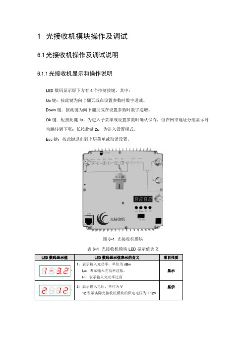
1光接收机模块操作及调试6.1光接收机操作及调试说明6.1.1光接收机显示和操作说明LED数码显示屏下方有4个控制按键,其中:Up键:按此键为向上翻页或在设置参数时数字递减。
Down键:按此键为向下翻页或在设置参数时数字递增。
Ok键:短按此键1s,为进入子菜单或设置参数时确认保存,但在网络地址分组显示时为跳转到下页;长按此键2s,为进入设置模式。
Esc键:按此键退出到上层菜单或取消设置。
图6-1 光接收机模块表6-1 光接收机模块LED显示值含义1:输入光功率(不可设置)2:输入电压(不可设置)3:机壳温度(不可设置)4:输出电平(不可设置)AGC:自动增益模式(不可设置)A1:OUT1和OUT2端口下行衰减(可设置),长按Ok键出现数字闪烁,再按Up、Down键调节(设置范围0~15 dB ,步进为1dB,此项用来调节输出电平大小,衰减值加1dBm,输出电平减1 dBm),短按Ok保存且退出闪烁设置状态。
E1:OUT1和OUT2端口下行均衡(可设置),长按Ok键出现数字闪烁,再按Up、Down键调节(设置范围0~15 dB,步进为1dB,此项是对光接收机高低频输出电平进行差值补偿,均衡值加1dBm,差值减小1 dBm),短按Ok保存且退出闪烁设置状态。
C:射频频道数(可设置),长按Ok键出现数字闪烁,再按上下键调节(设置范围1~99,步进为1,设置不同的值会影响输出电平的精度,此项通常使用出厂默认设置),短按Ok保存且退出闪烁设置状态。
BASE:设备基本信息,短按Ok键进入后,依次显示以下内容:P/H/G:分别是IP地址,子网掩码,网关等网络地址,其设置方法相同且如下:一个有效的网络地址格式为A.B.C.D ,在这里是分组显示和设置的1)进入显示条目2)按设置(长按Ok 键>2s), 到条目内容闪动, 进入设置状态3)按Down/Up 设置网络地址A 组内容4)按Ok (短按) 切换到网络地址B 显示, 按Down/Up 设置5)按Ok (短按) 切换到网络地址C 显示, 按Down/Up 设置6)按Ok (短按) 切换到网络地址D 显示, 按Down/Up 设置7)按Ok (短按) 保存以上显示内容, 回到显示条目, 取消闪烁。
交换及接入网设备操作规程

交换及接入网设备操作规程
1、设备接入规程
(1)在接入网设备之前,需要确认设备是否符合工作要求,并做好设备接入前的准备工作。
(2)安装设备时需要确保设备的电源、网络接口和其他必需的连接都已连接并且没有故障。
(3)接入网设备需要使用专业工具进行接入,确保接入过程中不会损坏设备。
(4)接入完成后,需确保设备已经连接到网络,并且能够正常工作。
2、设备交换规程
(1)在进行设备交换之前,需要对待交换的设备进行全面的检查,确保设备正常工作。
(2)交换设备需要提前做好工作计划,包括交换的时间、地点、人员安排等。
(3)交换过程中需要确保原设备和新设备都已经断开连接,并且设备交换过程中需要有专人负责监督设备的拆卸和安装。
(4)交换完成后,需确保新设备已经连接到网络,并且能够
正常工作。
3、其他注意事项
(1)在设备接入和交换过程中,需要确保设备连接的安全性,防止设备遭到破坏或者被盗。
(2)在设备交换完成后,需要对设备进行全面的测试,包括
设备连接、网络通信、设备性能等,确保设备能够正常工作。
(3)在设备接入和交换过程中,需要尽量减少对网络的影响,保证网络的稳定性和正常运行。
接收机至安全操作及保养规程
接收机至安全操作及保养规程在广泛应用于各种场合,有着广泛用途的无线电设备中,接收机是其中不可或缺的一部分,常用于收听广播、音频信号等,为我们带来了不少便利。
然而,为了正确、安全地使用接收机,并能使其维持长时间、高质量的性能,我们需掌握一些安全操作及保养规程。
安全操作规程1.接地保护。
务必将接收机接地,以避免静电、雷电等自然灾害对接收机的影响,并可保证使用人员的人身安全。
2.耳机使用注意事项。
在长时间使用耳机的情况下,使用者可能会出现耳鸣、头晕等不良症状。
为了保护听力,我们应使用舒适的耳机,并避免音量过大。
3.注意信号频率选择。
在使用接收机时,不同频段的信号具有不同的传播能力,在信道环境存在广泛的多径传播或其他干扰情况时,应根据情况选择适当的频率,以获得更好的接收效果。
4.网络连接注意事项。
接收机可能被连接到局域网或互联网上,如需与外部设备进行连接,为了避免信息泄露等安全问题,我们应遵守网络安全管理规程,并采取相应的防护措施。
5.使用时的电源及接线。
在使用接收机时必须使用于设备匹配的合适电源,同时电源线接触点要稳定牢靠,避免因连接不良而造成电源故障。
接收机保养规程1.定期检验清洁。
为了保证接收机正常使用,我们应该定期对其进行检验、校准,及时处理存在的问题。
同时,在日常使用中应遵守清洁保养规程,避免机身受到污染、腐蚀等现象,影响设备性能。
2.避免机身受到冲击。
接收机应放置于平稳、安全的位置上,避免受到冲击、震动等环境因素影响,以避免机身损坏,影响接收机的正常使用。
3.适当的温度湿度等环境条件保持。
在保养接收机时,我们需注意周围的环境因素,尤其是温度、湿度等因素。
避免使用在过于潮湿、高温、低温等极端环境中,从而达到保护设备的目的。
4.定期更换零件。
接收机中的一些零部件,如电容等,可能会随着时间的推移而失效,为了避免影响整个设备的使用,我们应该根据实际情况,及时更换可能存在问题的零部件。
5.避免顶限功率操作。
地铁综合监控系统设备IBP作业指导书
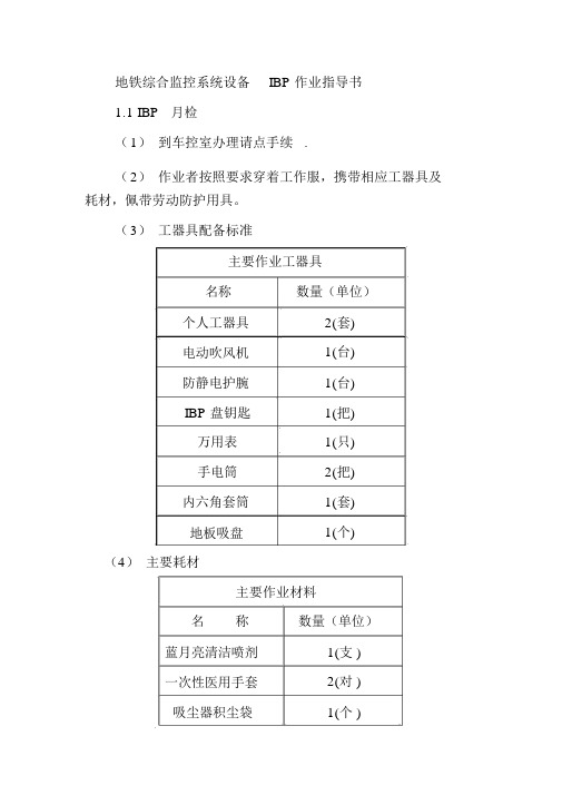
地铁综合监控系统设备IBP 作业指导书1.1 IBP月检(1)到车控室办理请点手续 .(2)作业者按照要求穿着工作服,携带相应工器具及耗材,佩带劳动防护用具。
(3)工器具配备标准主要作业工器具名称数量(单位)个人工器具2(套)电动吹风机1(台)防静电护腕1(台)IBP 盘钥匙1(把)万用表1(只)手电筒2(把)内六角套筒1(套)地板吸盘1(个)(4)主要耗材主要作业材料名称数量(单位)蓝月亮清洁喷剂1(支 )一次性医用手套2(对 )吸尘器积尘袋1(个 )抹布2(条 )压缩空气喷洁剂1(瓶 )液晶屏幕清洁套1(套 )装油刷 13mm1(把 )油刷 50mm2(把 )( 5)IBP月检作业完成情序号作业项目作业标准备注况()外观检查,应完好无破损,表确认设备面清洁1存在并且完整设备表面干净、清2盘面清洁洁、无灰尘盘面的指示灯亮。
若盘面的指示灯不亮,检查电源线是检查盘面3否正确连接(由指的指示灯示灯到端子的连线)及指示灯的电源线的焊接是否脱4 5 6 7 8 9焊。
按钮动作灵活、无按压灯泡试验按钮卡阻;按钮灯都能正常亮灯检查 IBP 盘钥匙是否在正确位上的钥匙置,能否实现转换开关控制功能观察各种指示灯显了解设备示,观察所有开关、的运用情按扭状态及标示是况否齐全完好,及时处理不良部件检查设备外表是否检查设备有裂纹、刮花或破损等现象,如果有,外表应根据损坏程度作出适当的处理连接件紧卡座牢固不松动,螺丝紧固无松动;固,检查及电线无松脱,锈化、调整破皮IBP 盘按钮检查 IBP 盘按钮和和指示灯指示灯状态是否与状态显示现场设备运行一致检查电缆沟槽干净、无杂物;电缆芯线无电缆沟槽、10伤痕、无破皮、无防鼠检查虫鼠咬伤等情况,并有防鼠措施参数记录:检修前存在的问题检修后还存在的问题(6)质量检查由①号对作业时所记录的相关数据进行复查,确认无误后,作业的两名作业人员对记录数据进行签认。
(7)作业结束作业结束后,作业人员应关闭打开的柜门,复查试验好才离开;整理好工器具及防护用品;离开设备房应重新锁好房门,回到车控室归还钥匙、消记后,在车控室值班员处办理消点手续。
通信设备安装与调试操作规范
通信设备安装与调试操作规范第一章安装准备工作 (3)1.1 工作现场检查 (3)1.1.1 环境检查 (3)1.1.2 设备检查 (4)1.2 工具与设备准备 (4)1.2.1 工具准备 (4)1.2.2 设备准备 (4)1.3 安全措施落实 (4)1.3.1 安全培训 (4)1.3.2 安全防护 (5)1.3.3 应急处理 (5)第二章设备搬运与储存 (5)2.1 设备搬运方法 (5)2.1.1 搬运前的准备工作 (5)2.1.2 搬运过程中的注意事项 (5)2.1.3 搬运后的检查 (6)2.2 设备储存要求 (6)2.2.1 储存环境要求 (6)2.2.2 设备摆放要求 (6)2.2.3 设备储存期限 (6)第三章设备安装 (6)3.1 安装位置确定 (6)3.2 设备固定与接线 (6)3.3 安装质量检查 (7)第四章通信线路连接 (7)4.1 线路检查与整理 (7)4.1.1 检查要求 (7)4.1.2 检查流程 (7)4.1.3 整理要求 (7)4.2 线路连接方法 (8)4.2.1 连接原则 (8)4.2.2 连接步骤 (8)4.2.3 连接注意事项 (8)4.3 线路连接质量检查 (8)4.3.1 检查标准 (8)4.3.2 检查方法 (9)4.3.3 检查流程 (9)第五章设备调试 (9)5.1 调试准备 (9)5.1.1 调试前,需对通信设备进行全面的检查,确认设备安装符合规范要求,设备部件齐全,接线正确。
(9)5.1.2 准备调试所需的工具、仪器及测试线缆,包括但不限于信号发生器、频率计、示波器、网络分析仪等。
(9)5.1.3 根据设备的技术说明书和调试大纲,编写调试方案,明确调试步骤、方法和预期目标。
(9)5.1.4 确认调试现场的安全措施,包括电源隔离、防静电、防摔等措施。
(9)5.1.5 保证调试人员具备相应的资质和技能,了解设备的工作原理和调试方法。
(9)5.2 功能测试 (9)5.2.1 根据设备的功能说明书,逐一测试设备的基本功能,包括但不限于发射、接收、切换、调制、解调等。
四通道卫星接收机说明书

四通道卫星接收机使用说明书目录1安全注意事项 (2)2概述 (3)2.1产品功能及用途 (3)2.2外形尺寸(1U机箱) (3)3主要特点 (4)4技术规格与指标 (4)4.1数据输入 (4)4.2数据输出 (5)4.2.1ASI接口 (5)4.3网络管理接口 (5)4.4辐射及安全要求 (5)5系统组成及工作原理 (5)5.1系统组成 (5)5.2工作原理 (7)6安装指南 (7)6.1安装准备 (7)6.2设备安装流程 (8)6.3环境条件要求 (8)6.4接地要求 (9)6.4.1机柜接地 (9)6.4.2设备接地 (9)6.5线缆的连接 (9)6.5.1电源线的连接 (9)6.5.2信号线的连接 (10)7前面板操作指南 (10)7.1键盘功能 (10)7.2菜单选择 (11)7.2.1锁定状态显示 (11)7.2.2主菜单显示 (11)7.2.3射频设置 (11)7.2.4网络设置 (12)7.2.5保存当前设置 (13)7.2.6加载设置 (13)7.2.7版本号 (14)7.2.8选择语言种类(中文和英文) (14)7.2.9错误信息 (14)7.3系统运行错误及排除 (14)7.3.1指示灯状态 (14)7.3.2常见故障排除 (15)8网络管理器操作指南 (15)8.1NMS登陆 (16)8.2添加频点 (17)8.3添加设备 (18)8.4修改设备 (19)8.5查看和设置设备参数 (21)8.5.1卫星参数 (22)8.5.2信号监测 (23)8.6网管软件公共功能 (23)前言感谢您选用本公司的产品。
本手册详细介绍了产品的性能、安装及操作方法,无论您是第一次使用该产品,还是以前接触过很多类似产品,都必须在使用前仔细阅读本手册。
收货检查打开设备包装箱校验物品,务必检查小部件的包装材料,对照产品装箱清单或者下列项目检查包装箱中的物品:四通道卫星接收机 1台交流输入电源插线 1根ASI 线 1根如果这些项目与清单不符合,请立即通知我公司。
酒店卫星有线电视系统

酒店卫星及有线电视系统一、卫星电视系统概述为了在酒店中制造一个和谐、舒适和轻松的生活环境,设计卫星及有线电视接收系统是十分必要的,通过卫星及有线电视接收系统图像资料的传输能给酒店提供一个和谐的生活环境。
要求采用以有线电视为主,卫星电视为辅的系统,通过接收鑫挪一号卫星提供数套免费、收费电视节目,并经过前端设备处理后,混入酒店内有线电视系统专用射频信号分配网络进行传输,及时为客房提供国内外新闻信息、金融行情、丰富多彩的娱乐节目。
本系统采用860MH带宽、邻频双向传输技术,使用专用的卫星/有线电视设备,构成一个多功能、宽带、高性能的电视图像信号实时传输系统。
二、卫星电视系统设计依据卫星电视系统的设计,系统的各项指标的确定都必须符合国家的有关规定,因此我们在制定本系统方案时依据的具体规定如下:1.《30MHz~1GHz声音和电视信号的电缆分配系统》GB6501-862.《民用建筑电缆电视系统工程技术规范》(国标报批稿)3.《有线电视广播系统技术规范》(国标报批稿)4.《30MHz~1GHz声音和电视信号的电缆分配系统验收规则》三、卫星电视系统组成及工作原理信号源本系统电视节目可以包括卫星电视、有线电视网接入、VOD点播节目三大类。
系统的组成网络传输是本系统重要的组成部分,因为它要保证信号的传输质量,以提高用户收视效果。
网络传输有四个部分组成:1线路传输网络的传输电缆是采用75欧姆同轴电缆,电缆在信号传输时,信号的幅度将有所衰减,主要有三种,其一是随着传输电缆长度的增加,幅度将衰减。
其二是电缆的衰减量与频率的平方根成正比。
其三是电缆的衰减量随温度升高而增加。
2干线放大器其作用是把经过干线传输衰减的信号进行放大,以提高信号的幅度,增加信号的传输距离。
但干线放大器对电缆的补偿范围是有一定限制的,因为如幅度补偿过大将引起图象失真,而幅度补偿太小,图象将有雪花产生,所以网络的设计就是要用户能正常收看的最佳电平。
而且干线放大器的信号放大还将引起系统交调和互调指标下降。
自动取样设备操作规程(3篇)

第1篇为确保自动取样设备的正常运行,保障采样工作顺利进行,同时确保操作人员的人身安全,特制定本操作规程。
二、适用范围本规程适用于公司所有自动取样设备的操作和维护。
三、操作步骤1. 操作前准备(1)仔细阅读本操作规程,了解设备的基本原理和操作方法。
(2)检查设备外观是否完好,电源、气源等是否正常。
(3)确保采样管路畅通,无堵塞现象。
(4)确认采样介质、样品容器等符合要求。
2. 设备启动(1)打开设备电源,等待设备自检完成。
(2)根据样品类型和采集要求,设置采样参数,如采样时间、流量、采样量等。
(3)开启气源,确保气路畅通。
3. 采样操作(1)将样品容器放置在采样平台上,确保其稳定。
(2)按下采样按钮,设备开始自动采集样品。
(3)采样过程中,密切关注设备运行状态,确保采样过程正常。
(4)采样完成后,关闭采样按钮,停止采样。
4. 设备关闭(1)关闭气源,确保气路无泄漏。
(2)关闭设备电源,等待设备完全停止运行。
(3)清理采样平台和设备表面,保持设备整洁。
四、注意事项1. 操作人员应熟悉设备的基本原理和操作方法,未经培训人员不得操作设备。
2. 操作过程中,严禁将手或任何物体伸入设备内部,以免造成人身伤害。
3. 采样前,应确保采样介质、样品容器等符合要求,以免影响采样结果。
4. 设备运行时,严禁调整采样参数,以免影响采样精度。
5. 设备维护保养应按照设备厂家提供的维护保养手册进行,定期对设备进行检查、清洁和润滑。
五、维护保养1. 定期检查设备外观,确保无损坏、松动等现象。
2. 定期检查气路,确保无泄漏现象。
3. 定期清洁设备表面,保持设备整洁。
4. 按照设备厂家提供的维护保养手册进行定期维护保养。
六、记录1. 操作人员应详细记录设备运行参数、采样结果等,以便于分析、评估和改进。
2. 设备维护保养记录应完整、准确,便于追溯。
本规程自发布之日起实施,如有未尽事宜,可根据实际情况予以补充和修订。
第2篇一、目的为确保自动取样设备的安全、稳定、高效运行,防止操作失误和事故发生,特制定本操作规程。
PBI DMM-1000-C说明书

扩展板子网掩码:TS/IP输出信号源的子网掩码。
扩展板网关:TS/IP输出信号源的网关。
扩展板MAC地址:TS/IP输出信号源的Mac地址。
Gateway Mac Address:网关MAC地址设置。
制式:IP输出模式,可选择DVB和IP TV输出。
以上操作需要按提交执行才能生效。
Biss 1 Setup:Biss 1设置,需要输入密码。
Biss E Setup:Biss E设置,需要输入ID号和密码。
音频设置
音量l:音频电平,可在0-99范围内调节。
调制:音频模式,可选择Stereo、Left、Right和Mono,分别对应立体声、左声道、右声道和单声道。
音频语言:音频语言设置。
◎支持风扇温度控制,提高了风扇的寿命
2、HDMS网管基本操作
配置要求
操作系统:Windows2000以上,CPU:PIII/ 800 MHz以上,内存:256MDDR以上,数据库: MySQL Server 5.0
安装流程
Windows系统环境下,双击安装软件HDMS***.exe,即可启动安装程序然后按提示将HDMS安装完成。在Windows的程序菜单中找到Hdms子菜单,点击后弹出子菜单,点击HDMS或双击桌面上的HDMS图标,即可启动HDMS程序。
3、HDMS网管操作详细介绍
3.11300P、1400P解调器模块
1300P/1400P支持QPSK、QAM、COFDM、DVB-S2或ASI多种接口输入,对于加扰的节目,支持Irdeto、Viaccess、Conax、PowerCAM、国微等多种有条件解扰,转换为ASI和IP接口输出,IP输出包含Unicast单播和6路独立的Multicast组播输出,在DVB数字电视广播和Network网络之间架起了桥梁。
地面站操作规程
地面站操作规程引言概述:地面站是航天领域中至关重要的设施,用于与航天器进行通信和控制。
为了确保地面站的正常运行和通信质量,制定一套科学合理的地面站操作规程是必要的。
本文将详细介绍地面站操作规程的内容,包括设备检查、通信操作、故障处理和安全措施。
一、设备检查1.1 定期检查设备完好性地面站操作人员应定期检查各种设备的完好性,包括天线、收发器、调制解调器等。
检查包括外观是否损坏、连接是否牢固、电源是否正常等。
如发现设备故障或异常,应及时报告并采取相应的维修措施。
1.2 校准设备参数地面站操作人员应定期校准设备参数,确保其工作在最佳状态。
校准内容包括天线指向精度、收发器频率、调制解调器灵敏度等。
校准过程中应按照操作手册的要求进行,确保参数的准确性和稳定性。
1.3 清洁设备及工作环境地面站操作人员应定期清洁设备及工作环境,确保设备正常运行和通信质量。
清洁工作包括清除设备表面的灰尘和污垢、保持设备通风良好、防止设备被液体溅湿等。
同时,还应保持工作环境整洁有序,避免杂物堆放和电线交叉,以防止操作中的意外发生。
二、通信操作2.1 确定通信频率和协议地面站操作人员应根据任务需求,确定与航天器的通信频率和协议。
通信频率的选择应考虑到通信质量、频谱利用率和干扰等因素,确保通信的稳定和可靠。
2.2 确保通信链路畅通地面站操作人员应保持通信链路的畅通,确保与航天器的正常通信。
在通信过程中,应及时监测信号强度和质量,根据实际情况调整天线指向和收发器参数,以提高通信质量。
2.3 记录通信内容和数据地面站操作人员应准确记录通信内容和数据,包括通信时间、通信对象、通信内容等。
记录应详细、准确,以备后续分析和查证使用。
同时,还应做好数据备份工作,确保数据的安全性和可靠性。
三、故障处理3.1 及时发现故障并报告地面站操作人员应及时发现设备故障和通信异常,并及时向上级报告。
报告内容应包括故障现象、故障影响和可能原因等,以便上级作出相应的处理和决策。
通信设备安装与调试操作规程
通信设备安装与调试操作规程第1章设备安装前期准备 (6)1.1 设备选型与采购 (6)1.1.1 根据项目需求,充分调研市场,了解各类通信设备的功能、功能、兼容性及价格等因素。
(6)1.1.2 结合项目预算,选择符合国家及行业标准、质量可靠、功能稳定、性价比高的通信设备。
(6)1.1.3 与设备供应商进行沟通,明确设备的技术参数、配置要求、售后服务等事项,保证设备满足项目需求。
(6)1.1.4 完成设备采购合同签订,明确交货时间、质量保证、售后服务等条款。
(6)1.2 施工现场勘察 (6)1.2.1 对施工现场进行实地勘察,了解现场地形地貌、气候条件、供电及通信资源等情况。
(6)1.2.2 分析施工现场的实际情况,制定合理的设备安装方案和施工计划。
(6)1.2.3 根据现场勘察结果,提前协调解决施工现场可能影响设备安装的各类问题。
(6)1.3 施工材料准备 (6)1.3.1 根据设备安装方案,列出所需施工材料清单,包括线缆、辅材、工具等。
(7)1.3.2 对施工材料进行质量检查,保证材料符合国家标准及项目要求。
(7)1.3.3 合理安排施工材料采购、运输、储存等环节,保证施工材料及时供应。
(7)1.4 施工人员培训 (7)1.4.1 对施工人员进行专业技能培训,包括设备安装、调试、维护等内容。
(7)1.4.2 培训施工人员掌握相关安全生产知识,提高安全意识。
(7)1.4.3 对施工人员进行职业道德教育,保证施工过程中遵守相关法律法规及企业规章制度。
(7)1.4.4 培训结束后,对施工人员进行考核,合格后方可参与设备安装与调试工作。
(7)第2章设备安装基本要求 (7)2.1 设备安装环境要求 (7)2.1.1 设备安装区域应具备良好的通风条件,保证设备正常运行时所需散热。
(7)2.1.2 设备安装场所的温度、湿度应满足设备说明书规定的环境条件。
(7)2.1.3 设备安装区域应保持干燥、清洁,避免腐蚀性气体、灰尘等对设备的损害。
PBI DCH4000P说明手册
DCH-4000P Series Professional Digital DecoderUser ManualTable of contents1. SAFETY (1)2. TECHNICAL INTRODUCTION (2)2.1 Features (2)2.2 Factory Options (2)3. INSTALLATION (3)3.1 Inspection and Test (3)3.2 Functional Self Test (4)3.3 Mounting (4)4. FRONT PANEL (4)4.1 Front Panel List (4)4.2 Indicator LEDs (4)4.3 Liquid Crystal Display (5)4.4 Keypad (5)4.5 Common Interface (5)5. REAR PANEL (6)5.1 Power Supply (6)5.2 Output Connectors (6)5.3 ASI Input Connector (7)5.4 RS-232 Interface (7)5.5 Ethernet Interface (7)5.6 TS/IP Interface (Factory Optional) (7)6. INSTALLATION (7)6.1 Main Menu (7)6.2 System Menu (8)6.2.1 Local Setup (8)6.2.2 Setting up the Trap IP Address (8)6.2.3 Editing the Unit Name (9)6.2.4 Checking the Properties (9)6.2.5 Recover Factory Default Settings (9)6.2.6 Setting Machine Type (9)7. Manual for DCH-4000P-30S /-30T/-30C/-30S2 (9)7.1 Menu Structure for DCH-4000P-30S /-30T/-30C/-30S2 (9)7.2 Setting Inputs for DCH-4000P-30S /-30T/-30C/-30S2 (11)7.2.1 Checking Status of Inputs (11)7.2.2 Setting the Tuner Parameters (11)7.3 Setting Outputs for DCH-4000P-30S /-30T/-30C/-30S2 (13)7.3.1 Checking Status of Outputs (13)7.3.2 Setting Common Interface (14)7.3.3 Setting the Parameters of Decoder (14)7.3.4. Setting the ASI1 Output (15)7.3.5. Setting the ASI2/SDI Output (15)7.3.6. Setting the Mux/Filter (15)8. Manual for DCH-4000P-41S /-41T/-41C/-41S2 (15)8.1 Menu Structure for DCH-4000P-41S /-41T/-41C/-41S2 (15)8.2 Setting Inputs for DCH-4000P-41S /-41T/-41C/-41S2 (18)8.2.1 Checking Status of Inputs (18)8.2.2 Setting the Tuner Parameters (18)8.2.3 Setting the Ethernet Connector (18)8.3 Setting Outputs for DCH-4000P-41S /-41T/-41C/-41S2 (19)9. Manual for DCH-4000P-42S /-42T/-42C/-42S2 (19)9.1 Menu Structure for DCH-4000P-42S /-42T/-42C/-42S2 (19)9.2 Setting Inputs for DCH-4000P-42S /-42T/-42C/-42S2 (21)9.3 Setting Outputs for DCH-4000P-42S /-42T/-42C/-42S2 (22)9.3.1 Setting the Ethernet TS over IP output (23)9.3.2 Other output settings for DCH-4000P-42S /-42T/-42C/-42S2 (23)10. REMOTE MONITORING AND CONTROL (23)10.1 Install HDMS to a PC (23)10.2 Connect to HDMS (23)10.3 Login to HDMS (24)10.4 Add DCH-4000P-xx to HMDS (24)10.5 DCH-4000P-xx in HDMS (24)10.6 Other Settings (25)11. FAQ (25)12. Appendix (25)12.1 Specification (25)1. SAFETYPlease read this chapter before installation and use of the deviceThis equipment is provided with a protective earthing ground incorporated in the power cord.The main plug shall only be inserted in a socket outlet provided with a protective earth contact.Any interruption of the protective conductor, inside or outside the device, is likely to make the device dangerous.The device described in this manual is designed to be used by properly-trained personnel only. Adjustment, maintenance and repair of the device shall be carried out by qualified personnel.No operator serviceable parts inside. Refer servicing to qualified personnel. To prevent electrical shock, do not remove covers.For the correct and safe use of the device, it is essential that both operating and servicing personnel follow generally accepted safety procedures in addition to the safety precautions specified in this manual.Whenever it is likely that safety protection is impaired, the device must be made in-operative and secured against unintended operation. The appropriate servicing authority must be informed. For example, safety is likely to be impaired if the device fails to perform the intended measurements or shows visible damage.WARNINGSz Do not use the equipment in moisture environment surroundings.Avoid direct contact with water.z Never place the equipment in direct sunlight.z The outside of the equipment may be cleaned using a lightly dampened cloth. Do not use any cleaning liquids containing alcohol, methylated spirit or ammonia etc.z For continued protection against fire hazard, replace line fused only with same type.2. TECHNICAL INTRODUCTIONDCH-4000P-xx is a professional IRD with a variety of input (including DVB over ASI, IP, QPSK, QAM, COFDM and DS3) and output (CVBS, SDI, ASI, DS3 and IP) combinations. An appropriate IP port equipped as an option supports DVB over IP applications. LAN control and monitoring are achieved with TCP/IP, SNMP and HDMS*.(*Headend Devices Management System, a remote management software)2.1 Featuresz Fully complies with MPEG-2, MP@ML and DVB-S/-T/-C standardsz IP input or output with UDP/RTP (optional)z Multicast and Unicast on IPz Supports PAL, NTSC or SECAMz Supports various Conditional Access systemsz SDI video output with digital audio embeddedz Two sets of independent ASI outputsz Automatic PMT updatez Compatible with Multiple De-encrypt CI modulesz DS3 I/O for TS (optional)z Switchable audio sound trackz Teletext VBI, EBU subtitle and DVB subtitlez Upgradeable through LANz Easy-to-use LCD menu2.2 Factory OptionsFigure 2.1 Factory Option list of DCH-4000P series3. INSTALLATIONWarning:This equipment is provided with a protective earthing ground incorporated in the power cord.The main plug shall only be inserted in a socket outlet provided with a protective earth contact.Any interruption of the protective conductor, inside or outside the instrument, is likely to make the instrument dangerous. The type of main plugged shipped with each instrument depends on the country of application.Caution:Do not connect AC power until you have verified that the line voltage is correct and the proper fuses are installed. The equipment requires a power source of either 50/60 Hz at 110V or 50/60 Hz at 240V. The voltage ranges for these nominal voltage values are shown in the table:POWER REQUIREMENTInput voltage 90-260 Vrms auto selectFrequency 47 to 63 HzPower 50 VA max. / 30 VA typical.Current 110 V/0.27A or 240 V/0.125A typicalCaution:Be sure the supply voltage is within the specified range.Checking the fuses:The recognized recommended fuses are size 5 by 20 mm, rate T 2.0A, 250 V (UL and IEC approved).The line fuse is housed in a small container besides the power connector on the rear panel.To check the fuse, insert the tip of a screwdriver in the slot at the middle of the container and pry gently to extend the fuse where there is a little tap and pull out the fuse gently. The fuse is attached to the line module and cannot be removed.3.1 Inspection and TestCheck if the devise has any visible damage. If everything seems all right, power can be applied to the device. The main socket and fuse are located at the rear panel of the device.When the device is turned on, verify that the display shows the following message:DCH-4000P (factory default unit-name)IP: 168.192.1.21 (factory default IP Address)If no message is shown in the display or there is not light in the display, the device isdefective and has to be returned for servicing.3.2 Functional Self TestNo specific functional self test is needed.The device has been factory tested according to recognized test procedures and is ready for operation.3.3 MountingThe environment should be relatively dust free, free of excessive vibration and the ambient temperature between 0 ℃ to 40 ℃. Relative humidity of 20% to 80% (non-condensed) is recommended.Air intake for cooling is achieved via holes at the side of the device and the fans inside. The air flow should not be obstructed. Therefore, the device has to be placed on a flat surface, leaving some space at the sides of the device.When in operation, the internal temperature should not exceed the limit of 70 ℃.4. FRONT PANEL4.1 Front Panel ListFigure 4.1 Front Panel of DCH-4000P-xx Series Receiver4.2 Indicator LEDsThere are 3 LED-indicators:-POWER: the status of the power supplygreen: the power is turned onoff : the power is turned off-TUNER LOCK: the status of the tunergreen: The incoming QPSK is locked by the tuner.off : there is no QPSK input signal or the signal is unlocked-ALARM: the status of input signal source, which includes IP input, QPSK signal input and DVB-ASI TS input.4.3 Liquid Crystal DisplayThe 2 x 20 character Liquid Crystal Display (LCD) shows all the required information about the selected parameters.The top row of the LCD shows the selected parameter. The bottom row indicates the present values and how these can be adjusted.The parameters are grouped in three menus:-the Inputs, which gives the full operation on inputs parameters-the Outputs, with the full operation control functions on outputs parameters-the Systems, gives the general device management parameters and informs about the device working status4.4 KeypadFigure 4.2 Keypad of DCH-4000P-xx seriesThe 6 keys on the front panel allow you to navigate in the information given on the LCD and to change parameters, when the device operates under local control.The <ENTER>-key is used to enter the main menu or a sub-menu. When you stand on the preferred menu, <ENTER> is used to active the parameter on the bottom line and allows you to change the value. It also finishes the input of new alphanumeric values and confirms the changes.The <>-and<>-keys are used to select between the main menus or sub-menus. When you stand on the preferred menu and the parameter is active, they are also used to change the numerical values. Selecting a digit with the <>-and <>-keys.The <EXIT>-key, is used to exit a menu without any action.4.5 Common InterfaceThere are two Common Interface slots. You can insert up to two different CAM modules for descrambling.5. REAR PANELFigure 3.2 Rear Panel of DCH-4000P-xx SeriesB1 TS/IP Input/Output interfaceB2 XRL L interfaceB3 XRL R interfaceB4 RGB/YUV interface (G/Y)B5 RGB/YUV interface (B/U)B6 RGB/YUV interface (R/Y)B7 CVBS2 Output interfaceB8, B18 ASI2/SDI output interfaceB9, B19 ASI1 output interfaceB17 ASI input interfaceB10 RS-232interfaceB11 Tuner Loop Out interfaceB12 Tuner In interfaceB13 Power socket, AC 90~260VB14 CVBS1 Output interfaceB15, B16 L-Audio-R interfaceB20 Ethernet interface for remote management systemB21 Grounding5.1 Power SupplyThe power cord is inserted to an IEC main socket at the side of the device.Check that the power cord is suitable for the country where the device will be used.A standard power cord with a European DIN 49441 two pin main plug is delivered togetherwith the device.The line fuses are housed in a small container at the side of the power supply connector. 5.2 Output ConnectorsThe ASI interface B9), B19) and ASI2 interface B8), B18) are two pairs of independent ASI output. Both use female BNC connectors, with 75 Ohm impedance. The ASI interface B18) and B19) are used as a redundant output of B8) and B9) out.Note: the B8), B18) interface could be configured as SDI with Audio embedded. Please refer to Chapter 7.3.5.5.3 ASI Input ConnectorThe ASI input B17) is a 75 ohm female BNC connector.5.4 RS-232 InterfaceThis interface is a 9-pins female sub-D connector. The RS-232 interface is only used for factory software upgrade and configuration, so you are not allowed to connect any cable to the RS-232 connector, as that could damage the device.5.5 Ethernet InterfaceAn RJ-45 connector B20) provides a remote control interface.5.6 TS/IP Interface (Factory Optional)An RJ-45 connector B1) provides a streaming stream over IP input or output.6. INSTALLATIONThe device allows you to configure, control and monitor through the Keypad and front panel display when a remote control system is not used.6.1 Main MenuTurn on the device and wait for 8 to 10 seconds, while the device will complete self inspection and configuration. The top row of the LCD shows the name of the device. The local IP address is displayed on the bottom row of the LCD.Note: the local IP address can be changed in the System Menu.Use the <ENTER>-key to enter on the Main Menu. The <>-and<>-keys are used to choose between the three main menus.Figure 6.1 Main Menu6.2 System MenuThe system menu provides information about the general functions, the surroundings equipment and the hardware used.Figure 6.2 System Menu6.2.1 Local SetupEach DCH-4000P-xx has an IP address, a network sub mask and a gateway. These must be set to an appropriate value for the network over which the unit can be accessed by the remote control system such as the HDMS.-IP Address: The IP address for the unit.-Network Mask: The network mask for the subnet to which the unit is connected.-Gateway: The gateway for the network to which this unit is connected.6.2.2 Setting up the Trap IP AddressThe DCH-4000P-xx provides a Monitor Center IP address. You can set this to be the same IP address of the Monitor Center, which is typically a PC in order to allow the device to send messages to the monitor center. If the DCH-4000P-xx is connected with the HDMS remote management system, the Trap IP address is typically set to be the IP address of the PC on which the HDMS has been installed.6.2.3 Editing the Unit NameThe DCH-4000P-xx allows you to edit the unit name which is displayed on the front panel LCD. The unit name should not be longer than 20 characters in ASCII format.6.2.4 Checking the PropertiesYou are allowed to check the properties information of the device.- MAC address: Factory-set MAC address which is guaranteed to be unique. You cannot configure this address.- FW Version: the version of the FPGA software.- SW Version: the version of the main software.6.2.5 Recover Factory Default SettingsAll the user configurable parameters will be set to the factory default settings, including IP address and the unit name. Note that the unit will not be connected with the HDMS remote management system until the IP is properly configured.6.2.6 Setting Machine TypeThis setting is reserved for factory-setting, and you are not allowed to access this menu. 7. Manual for DCH-4000P-30S /-30T/-30C/-30S27.1 Menu Structure for DCH-4000P-30S /-30T/-30C/-30S2Note: only the Inputs menu differs from DCH-4000P-30S /-30T/-30C/-30S2 models.Figure 7.1 Full Menu Structure for DCH-4000P-30SFigure 7.2 Inputs Menu Structure for DCH-4000P-30TFigure 7.3 Inputs Menu Structure for DCH-4000P-30CFigure 7.4 Inputs Menu Structure for DCH-4000P-30S27.2 Setting Inputs for DCH-4000P-30S /-30T/-30C/-30S2Under Input Menu, you can monitor and configure the parameters of the Tuner.7.2.1 Checking Status of Inputs- ASI Input: locked or unlock indicate the status of the ASI input.- Tuner Input: when the QPSK/QAM/COFDM signal is locked by the tuner, the bit rate isdisplayed on the bottom row of LCD.7.2.2 Setting the Tuner ParametersTo receive the QPSK/QAM/COFDM signal, these parameters below must be set to appropriate values for the receiving antenna over which the device can receive the signal.For QPSK Tuner:- LNB Local Oscillator (L.O.) Freq: enter the frequency of the LNB in MHz.- Satellite Freq: edit the satellite down link frequency in MHz. The IF frequency will becalculated automatically.- Symbol Rate: enter the QPSK symbol rate.- LNB Voltage: select the correct LNB voltage output of the F-connector: Off, 13 V, 18 V. <A> - LNB 22KHz: activate the LNB 22 kHz control signal to the LNB: On or Off. <B>- Note: please contact the local satellite operator for the satellite frequency and symbol rate.<A> Normally, 13V switches the LNB to receive Vertical/Left hand polarizationwhile 18V receive Horizontal/Right hand.<B> Normally, 22KHz control signal switches the LNB to receive high band if any.For QAM Tuner:- Constellation: enter the modulation mode of the QAM signal.- Frequency: enter the frequency of the QAM signal in MHz.- Symbol Rate: edit the symbol rate to the proper value in KBaud.For COFDM Tuner:- Frequency: enter the proper frequency of the COFDM signal in MHz.For DVB-S2 Tuner:- LNB Local Oscillator (L.O.) Freq: enter the frequency of LNB in MHz.- Satellite Freq: edit the satellite down link frequency in MHz. The IF frequency will be calculated automatically.- Symbol Rate: enter the QPSK/8PSK symbol rate.- LNB Voltage: select the correct LNB voltage output of the F-connector: Off, 13 V, 18 V. <A> - LNB 22KHz: activate the LNB 22 kHz control signal to the LNB: On or Off. <B>- Note: please contact the local satellite operator for the satellite frequency and symbol rate.<A> Normally, 13V switches the LNB to receive Vertical/Left hand polarizationwhile 18V receive Horizontal/Right hand.<B> Normally, 22KHz control signal switches the LNB to receive high band if any. - Demodulation Mode: select the DVB-S or DVB-S2 demodulation mode.- Operation Mode: select the appropriate operation mode in the menu. There are QPSK 1/2, 2/3, 3/4, 4/5, 5/6, 8/9, 9/10 and 8PSK 2/3, 3/4, 3/5, 5/6, 8/9, 9/10 tochoose among.- Pilot: select Off or On according to the actual signal.- Roll-Off Factor: you can choose 0.2, 0.25 or 0.35.7.3 Setting Outputs for DCH-4000P-30S /-30T/-30C/-30S2Figure 7.5 Outputs Menu Structure for DCH-4000P-30S /-30T/-30C/-30S27.3.1 Checking Status of OutputsThere are 2 displays on the LCD for monitoring the status of the decoder and the common interface.- Decoder: OK or Alarms indicates the status of the decoder. You can use the <ENTER>-key to check detailed information in the submenu of the Decoder.- CI: You can check the information of the CAM Modules in Slot1 and Slot2.7.3.2 Setting Common InterfaceThere are 2 submenus: CI Source and Setup which allow you to set or select the parameters of the CI.- CI Source: select Tuner or ASI input to set the signal source of descrambling.- Setup: press the<> or <>-key to select the program which is expected to be descrambled, then press the <ENTER>-key to choose Slot1, or Slot2, or Bypass.Press the <EXIT>-key after configuration, and the following message will be shownon the LCD: “Confirm Changed? ENTER=YES, EXIT=NO”. If you want to keep thechanges, press the <ENTER>-key.0-xxxxx displays the program name, which signal source is ASI.1-xxxxx displays the program name, which signal source is TUNER.2-xxxxx displays the program name, which signal source is TS/IP (this is invalid for30 -10S/-11T/-12C/-13S2 series).3-xxxxx factory occupied.7.3.3 Setting the Parameters of DecoderYou can configure the parameters of Video and Audio of the program decoded by decoder.- Program: Press the <> or <>-key to select the program which is expected to be decoded. Press the <>-and <>-key to choose channel from 0 to 3, thenpress the <ENTER>-key to confirm.0-xxxxx displays the program name, which comes from ASI input.1-xxxxx displays the program name, which comes from TUNER input.2-xxxxx displays the program name, which comes from TS/IP input (this isinvalid for 30 -10S/-11T/-12C/-13S2 series).3-xxxxx displays the program name which comes from the CI.- Video: You can configure the video parameters of programs in this submenu. Press the <ENTER>-key to confirm and press the <EXIT>-key to cancel.Video Standard: you can select Auto or SECAM or NTSC or PAL for thecomposite video output.Screen: select the screen mode: 4:3 Full, 16:9 Full or 4:3 Letterbox.DVB Subtitle Lang: select the language of DVB Subtitle.EBU Subtitle Lang: select the language of EBU Subtitle.Subtitle Priority: configure the priority of Subtitle; choose whether DVB or EBUshould be first.- Audio: You can configure the audio settings in the submenu.Audio Level: use the <> <> <> <>-keys to modify the audio level withinthis range: 0~99.Audio Mode: select Stereo, Left, Right or Mono for soundtracks.Audio Language: select the language of the audio.7.3.4. Setting the ASI1 OutputUser can configure the settings of ASI1 in this menu.- ASI Source: select the signal source of ASI output: CI De-encrypted, TUNER, ASI Input or Mux-TS.- ASI Package Length: you can configure the package length of ASI output as 188 bytes orselect Bypass.Note: the Mux-TS is only valid when the Mux or Filter is enabled and turned on. The Mux-TS indicates not only the after-multiplexed TS when Mux is enabled, but also theafter-filtered TS when the filter is enabled.7.3.5. Setting the ASI2/SDI OutputThe ASI2/SDI port is user-configured as ASI output or SDI output.If the port is configured as ASI2, the configuration method is the same as ASI. (Please refer to the paragraph 7.3.4.)If the port is configured as SDI, there are two parameters which need to be set: Audio PID and Embed Audios.- Audio PID: press the <> <>-keys to choose the audio PID from 1~4.- Embed Audios: there are 4 options: none, one&two, two, and one.7.3.6. Setting the Mux/FilterNote: the Mux / Filter are alternative.For MuxMux Switch: the internal multiplexer could be switched On/Off.Bit Rate: set the output bit rate of the multiplexed TS in Kbps.TS ID: you can configure the TS ID to mark the multiplexed TS.Program List: the list of programs multiplexed. Press the <ENTER>-key to select the program which is expected to be multiplexed. A “*” will be displayed in the frontof the program name. Press the <ENTER>-key again to deselect a program.For FilterFilter Switch: the internal filter could be switched On/Off.Bit Rate: set the output bit rate of the filtered TS in Kbps.Source: select the source of the TS which is expected to be filtered.Program List: the list of programs filtered. Press the <ENTER>-key to select the program which is expected to be filtered away. A “*” will be displayed in the front of theprogram name. Press the <ENTER>-key again to deselect a program.8. Manual for DCH-4000P-41S /-41T/-41C/-41S28.1 Menu Structure for DCH-4000P-41S /-41T/-41C/-41S2Note: the Input menu differs from DCH-4000P-41S /-41T/-41C/-41S2 models according to the type of tuner.Figure 8.1 Full Menu Structure for DCH-4000P-41SFigure 8.2 Inputs Menu Structure for DCH-4000P-41TFigure 8.3 Inputs Menu Structure for DCH-4000P-41CFigure 8.4 Inputs Menu Structure for DCH-4000P-41S28.2 Setting Inputs for DCH-4000P-41S /-41T/-41C/-41S2In the Input Menu, you can monitor and configure the parameters of the Tuner.8.2.1 Checking Status of InputsThere are 2 displays on the LCD for monitoring the status of input.- ASI Input: locked or unlock indicates the ASI input status.- Tuner Input: when a satellite signal is locked via the tuner, the bit rate is displayed on the bottom row of the LCD.- IP IN: this indicates the status of the transport stream over IP input. The bitrate is displayed on the bottom row of the LCD, if IP input is valid.8.2.2 Setting the Tuner ParametersPlease refer to paragraph 7.2.2.8.2.3 Setting the Ethernet ConnectorThere is an Ethernet connector for receiving transport stream over IP. The Ethernet connector has user-configurable IP address, network mask and default gateway. These must be set to appropriate values for the network over which the transport stream over IP is received.- Source IP Addr: Enter the IP address for streaming IP input of the unit.- Source Network: Enter the network sub mask for the subnet to which the unit is connected for IP streaming traffic.- Source Gateway: Set the gateway for the network to which the unit is connected for IPstreaming traffic.- Source Mac Address: factory-set MAC addresses are guaranteed to be unique. Thereforeyou cannot configure the address.- Multicast IP Addr: Enter the IP address of the multicast stream for the transport streamover IP.-Multicast UDP Port: Enter the UDP port number of the TS over IP stream.- Protocol: select the protocol for multicast: UDP or RTP.- Output Smoothing: set the quality of TS which comes from the TS/IP input.Auto: the bit rate is variable.Disable: the unit let the TS pass by.Fixed Rate: the bitrate is fixed.- TS Bit Rate: set the bit rate of the TS comes from the TS/IP input. The setting is only valid when the output smoothing is configured as Fixed Rate.8.3 Setting Outputs for DCH-4000P-41S /-41T/-41C/-41S2Please refer to paragraph 7.3 for the setting method.Note that the TS over IP input also could be configured as the source of CI, ASI, ASI2 and Mux/Filter.9. Manual for DCH-4000P-42S /-42T/-42C/-42S29.1 Menu Structure for DCH-4000P-42S /-42T/-42C/-42S2Note: the Input menu differs from DCH-4000P-42S /-42T/-42C/-42S2 models according to the different type of tuner.Figure 9.1 Full Menu Structure for DCH-4000P-42SFigure 9.2 Inputs Menu Structure for DCH-4000P-42TFigure 9.3 Inputs Menu Structure for DCH-4000P-42CFigure 9.4 Inputs Menu Structure for DCH-4000P-42S29.2 Setting Inputs for DCH-4000P-42S /-42T/-42C/-42S2Please refer to paragraph 7.2 for the setting method.9.3 Setting Outputs for DCH-4000P-42S /-42T/-42C/-42S2Figure 9.5 Outputs Menu Structure for DCH-4000P-42S /-42T/-42C/-42S29.3.1 Setting the Ethernet TS over IP outputThe Ethernet connector could also be configured as the output of the transport stream over IP.The parameters listed below must be set to appropriate values for the network over which the transport stream over IP is broadcasted.- Stream IP Address: Enter the IP address for streaming IP output of the unit.- Stream Network Mask: Enter the network sub mask for the subnet to which the unit isconnected for IP streaming traffic.- Stream Gateway: Set the gateway for the network to which the unit is connected for IPstreaming traffic.- Stream Mac Address: factory-set MAC addresses are guaranteed to unique. Therefore youcannot configure the address.- Multicast IP address: Enter the IP address of the multicast stream for the transport streamover IP output.-UDP Port: Enter the UDP port number of the TS over IP stream output.- Protocol: select the protocol for multicast: UDP or RTP.- TS Pkts Per UDP: set the number of the TS packages encapsulated in one UDP package.The valid range goes from 1 to 7.- Time To Live: set the number of the routers over which the TS over IP can be transmitted.The valid range goes from 1 to 5.- Type of Service: select the type of service. There are: Normal, Min Monetary Cost, MaxReliability, Max Throughput or Min Delay optional.- Source: select the source of the TS over IP streaming output. There are: ASI Input, CI De-encrypted or TUNER.9.3.2 Other output settings for DCH-4000P-42S /-42T/-42C/-42S2Please refer to paragraph 7.3 for the other output setting method.10. REMOTE MONITORING AND CONTROLThe DCH-4000P-xx series provides an Ethernet remote control interface for user remote control or supervise one or multiple DCH-4000P-xx via the Headend Devices Management System (HDMS).10.1 Install HDMS to a PCThe HDMS Installation.exe file could be found on the CD-ROM which is enclosed in the original package. Detailed information about installation can be found in the HDMS Reference Guide.10.2 Connect to HDMSAfter installation of HDMS, you need to configure the local settings of the DCH-4000P-xx (s) which is/are expected to connect to the remote control network. Please refer to paragraph 6.2.1.。
PBI-4000M-UV专业级全频道捷变式邻频电视调制器
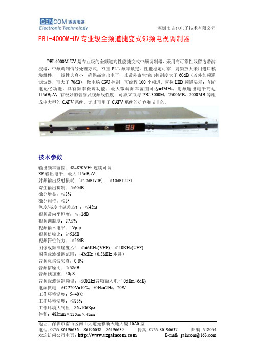
PBI-4000M-UV专业级全频道捷变式邻频电视调制器PBI-4000M-UV是专业级的全频道高性能捷变式中频调制器,采用高可靠性残留边带滤波器,中频调制信号处理方式;双重PLL频率锁定,性能稳定可靠;射频放大采用进口模块组件,非线性失真小,确保高输出电平;其带外寄生输出抑制度大于60dB(若外加频道滤波器,可大于70dB);微电脑CPU控制,可编程100个频道,两位LED频道显示;有断电记忆功能,具有频率微调功能,最大微调频率范围可达±4MHz,射频输出电平高达115dBμV,有极好的音频及视频线性度;可独立或与PBI-3000M,2500MB,2000MB等组成中大型的CA TV系统,尤其可用于CA TV系统的扩容和节目的。
技术参数输出频率范围:48~870MHz连续可调RF输出电平:最大115dBμV射频输出反射损耗:≥12dB(VHF);≥10dB(UHF)寄生输出抑制:≥60dB微分增益:≤3%微分相位:≤3°色度/亮度时延差△τ:≤45ns视频带内平坦度:≤±2dB视频调制度:87.5%视频输入电平:1Vp-p视频信噪比:≥52dB视频箝位能力:≥26dB图像载频准确度△f:≤±5KHz(VHF);≤10KHz(UHF)图像载波微调范围:±4MHz(0.5MHz步进)音频总谐波失真:0.8%音频信噪比:≥58dB音频预加重:50μS音频载波调制频偏:±50KHz(音频输入电平0dBm±6dB)电源供电:AC 220V±10%,50Hz±2Hz,20W工作环境温度:5~40℃工作环境湿度:≤85%工作环境大气压:86~106Kpa体积:483mm×320mm×45mm地址:深圳市南山区南山大道光彩新天地大厦16A6室地址:深圳市南山区南山大道光彩新天地大厦16A6室。
连接仪器装置操作规程(3篇)
第1篇为确保仪器装置的正常运行,提高实验结果的准确性,以下为连接仪器装置的操作规程,请使用者务必严格遵守。
二、操作规程1. 准备工作(1)仔细阅读仪器装置的操作说明书,了解其性能、特点及注意事项。
(2)确保仪器装置处于完好状态,无损坏、腐蚀等现象。
(3)准备所需的连接线、接头、适配器等配件。
2. 连接步骤(1)将仪器装置的电源线连接到电源插座,确保电源线无破损、裸露。
(2)根据仪器装置的接口类型,将连接线的一端插入仪器装置的接口,另一端插入相应设备的接口。
(3)对于需要调节压力、流量等参数的仪器装置,根据实际需求调整至合适值。
(4)检查连接线是否牢固,避免因松动导致仪器装置无法正常工作。
(5)连接好仪器装置后,确保各部分连接无误,方可开启仪器装置。
3. 注意事项(1)连接过程中,避免用力过猛,以免损坏仪器装置。
(2)对于精密仪器装置,连接时要轻拿轻放,防止震动。
(3)连接线、接头、适配器等配件应保持干燥、清洁,避免因潮湿、污染等因素影响仪器装置的运行。
(4)连接过程中,如发现连接线、接头、适配器等配件存在异常,应立即停止操作,检查原因并更换。
(5)仪器装置连接完毕后,检查各部分是否运行正常,如有异常,应立即停止使用,并通知专业人员检查。
4. 保养与维护(1)定期检查仪器装置的连接线、接头、适配器等配件,如有磨损、损坏等情况,应及时更换。
(2)保持仪器装置的清洁,避免灰尘、杂物等进入。
(3)根据仪器装置的使用说明书,定期进行保养与维护。
三、总结以上为连接仪器装置的操作规程,请使用者严格遵守。
在操作过程中,如遇到问题,应及时停止操作,并寻求专业人员帮助。
通过正确、规范的连接操作,确保仪器装置的正常运行,提高实验结果的准确性。
第2篇为确保仪器装置的正常运行和操作安全,以下为连接仪器装置的操作规程,请严格按照以下步骤执行:一、准备工作1. 检查设备状态:在开始连接前,确保所有仪器设备处于良好状态,电源线、连接线等无破损,设备表面无污渍。
PBI接收机及调制器操作规程(DOC)
信号源系统操作规程信号源系统主要包括两种设备:PBI DVR-1000工程专用卫星数字电视接收机、PBI-4000MUV 广播级全频道捷变式邻频调制器。
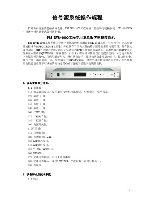
PBI DVR-1000工程专用卫星数字电视接收机PBI DVR-1000工程专用卫星数字电视接收机采用最新STi-5518芯片,完全符合广电总局颁发的标准和MPEG-2&DVB-S标准,并已预存了国内大量的数字压缩的卫星电视节目,具有图文接收功能,PID手动输入功能,断电记忆功能和EPG节目指南显示功能;采用增强式OSD中英文屏幕显示菜单和QPSK解调一体调谐器,门限低;有网络和转发器自动搜索功能,可方便卫星数字电视信号的接收;且应用最新型软、硬件结合技术,保证长期稳定可靠的运行。
其功能齐全,操作方便,画面品质一流,完全满足中国CATV前端卫星数字电视接收的各项要求,是各种有线电视前端系统不可或缺的高稳定的CATV前端卫星数字电视接收机。
1、设备主要部分介绍:1.1 前面板(1)液晶显示窗口:显示卫星接收机输出频道,电源指示,信号指示;(2)频道 + 键;(3)频道 - 键;(4)音量 + 键;(5)频道 - 键;(6)“OK”键;(7)“MENU”键;(8)“EXIT”键;(9)电源开关键。
1.2后面板:(1)视频输出口;(2)音频输出口L,R;(3)LNB输入端口;(4)LNB输出端口;(5)Y, Cb,Cr输出口;(6)RS232口;(7)交流电源插座:可用于电源串接;(8)交流电源输入:连接220V/50Hz 交流电源(需良好接地);(9)保险座。
2、设备特点及技术参数2.1 特点1)完全符合DVB-S和MPEG2标准2)LED显示,前面板轻触按键操作及友好操作界面3)自动网络和转发器搜索功能并更新码流信息4)可存储2000个频道的信息5)可进行视频PID和音频PID的设置6)具有断电记忆功能7)支持OSD电视图文VBI (DVB ETS 300 706) 和字幕功能8)256彩色屏幕显示,支持英文、法文、德文、俄文、西班牙文、意大利文、中文及阿拉伯文等多种语言系统9)电子节目指南EPG功能,并支持PIG(Picturre in Graphics)画中画显示功能10)具有NTSC/PAL/AUTO制式转换功能11)通过RS-232接口由电脑或另一台DVR-1000可进行软件的升级(机对机拷贝功能)3、设备安装及操作3、1 安装3.1.1认真仔细做好F接头,不可让屏蔽层的丝网和铜芯接触,以免短路。
- 1、下载文档前请自行甄别文档内容的完整性,平台不提供额外的编辑、内容补充、找答案等附加服务。
- 2、"仅部分预览"的文档,不可在线预览部分如存在完整性等问题,可反馈申请退款(可完整预览的文档不适用该条件!)。
- 3、如文档侵犯您的权益,请联系客服反馈,我们会尽快为您处理(人工客服工作时间:9:00-18:30)。
信号源系统操作规程信号源系统主要包括两种设备:PBI DVR-1000工程专用卫星数字电视接收机、PBI-4000MUV 广播级全频道捷变式邻频调制器。
PBI DVR-1000工程专用卫星数字电视接收机PBI DVR-1000工程专用卫星数字电视接收机采用最新STi-5518芯片,完全符合广电总局颁发的标准和MPEG-2&DVB-S标准,并已预存了国内大量的数字压缩的卫星电视节目,具有图文接收功能,PID手动输入功能,断电记忆功能和EPG节目指南显示功能;采用增强式OSD中英文屏幕显示菜单和QPSK解调一体调谐器,门限低;有网络和转发器自动搜索功能,可方便卫星数字电视信号的接收;且应用最新型软、硬件结合技术,保证长期稳定可靠的运行。
其功能齐全,操作方便,画面品质一流,完全满足中国CATV前端卫星数字电视接收的各项要求,是各种有线电视前端系统不可或缺的高稳定的CATV前端卫星数字电视接收机。
1、设备主要部分介绍:1.1 前面板(1)液晶显示窗口:显示卫星接收机输出频道,电源指示,信号指示;(2)频道 + 键;(3)频道 - 键;(4)音量 + 键;(5)频道 - 键;(6)“OK”键;(7)“MENU”键;(8)“EXIT”键;(9)电源开关键。
1.2后面板:(1)视频输出口;(2)音频输出口L,R;(3)LNB输入端口;(4)LNB输出端口;(5)Y, Cb,Cr输出口;(6)RS232口;(7)交流电源插座:可用于电源串接;(8)交流电源输入:连接220V/50Hz 交流电源(需良好接地);(9)保险座。
2、设备特点及技术参数2.1 特点1)完全符合DVB-S和MPEG2标准2)LED显示,前面板轻触按键操作及友好操作界面3)自动网络和转发器搜索功能并更新码流信息4)可存储2000个频道的信息5)可进行视频PID和音频PID的设置6)具有断电记忆功能7)支持OSD电视图文VBI (DVB ETS 300 706) 和字幕功能8)256彩色屏幕显示,支持英文、法文、德文、俄文、西班牙文、意大利文、中文及阿拉伯文等多种语言系统9)电子节目指南EPG功能,并支持PIG(Picturre in Graphics)画中画显示功能10)具有NTSC/PAL/AUTO制式转换功能11)通过RS-232接口由电脑或另一台DVR-1000可进行软件的升级(机对机拷贝功能)3、设备安装及操作3、1 安装3.1.1认真仔细做好F接头,不可让屏蔽层的丝网和铜芯接触,以免短路。
3.1.2根据说明书上的卫星接收机连线图,将接收机上LNB输入端口用F 头的电缆线连接天线上高频头端口。
3.1.3卫星接收机A、V端口连接到调制器A、V输入端口,上述连接正确无误后,然后开卫星接收机电源。
3、2 设备操作3.2.1按卫星接收机面板上“MENU”键,进入系统主菜单画面,按面板上“▲,▼”键选“安装设定”,按“OK”进入“天线设定”项,这项是要把本振频率参数写入。
LNB栏‘关’状态。
高频头本振频率写一个值,你的高频头上本振频率值,如5150MHZ或其他值时,LNB“关”,其它不变,用“,”选择需要接收的卫星,然后按“EXIT”返回。
3.2.2选择“频道搜索”项,按“OK”键进入,输入以下重要参数,下行频率,符号率,极化。
(输入数字、极化时请按面板左、右键选择),然后观看EB/NO有无电平强度指示。
3.2.3 EB/NO栏有电平强度指示,按面板上“▲,▼”键移动到手动搜索处,按“OK”键,进行搜索。
4、常见故障及处理4、1 信号时有时无4.1.1 检查线路是否完好.重连一次;4.1.2 检查接收机的设置是否正确.重设一次;4.1.3 接收机供给高频头的电源电压输出正常吗?(水平极化方式为18至21.垂直极化方式为11至15伏)拿万用表测测;4.1.4 检查接线板地线是否有漏电现象;4.1.5 春分、秋分季节发生的"日凌"等天文现象也会使卫星电视接收暂时失去信号,请增加天线尺,以减低它的干扰;4.1.6 检查接收机的输出电源是否与其他供电设备有冲突,清除冲突。
4、2 有图像没声音:4.2.1 检查音频线路连接是否完好.重连一次;4.2.2 检查接收机的音频设置是否正确.有的接收机带有音频开关和声道选择;4.2.3 节目加密也会造成有图像没声.或反之.属于正常;4.2.4 检查电视机上的音量是否打开;4.2.5 上面的检查都正确无.很有可能是接收机的音频输出出了问题,送修。
4、3 能收其它电视节.确收不到需要的电视节目4.3.1 检查接收机设置里的极化方式是否正确;4.3.2 上行或下行频率参数正确吗;4.3.3 把高频头的极化角调整到最佳.或高频头极化方式正确吗;4.3.4 把天线调整到最佳状态.最好使用专业的场强仪进行调试。
4、4 信号电平为零:4.4.1 检查接收机与天线之间的连线是否完好,重连一次,检查;4.4.2 检查高频头是否是完好的。
否,换个高频头试试,调整;4.4.3 检查接收机的极化设置是否与你的高频头匹配;4.4.4 检查接收机的输出电压是否正常.测测;4.4.5 检查天线位置、高频头的极化角是否正确;4.4.6 自然现象如:"日凌"现象等也会造成信号接收不稳定。
4、5 有声音没图像:4.5.1检查视频的线路连接是否正确,重连一次。
4、6 信号电平正常,但无信噪比和图像和声音:4.6.1 检查所有连线是否正确,重连一次;4.6.2 检查天线的位置是否正确,重调;4.6.3 检查接收机的设置是否正确,如:其极化角设置是否正确;4.6.4 检查接收机内部电源是否工作正常,重启接收;4.6.5 检查高频头的极化角是否正确。
4、7 没有任何信号:4.7.1 检查天线水平角、极化角、仰角有无变动;4.7.2 检查所有的连接线的连接是否正确和正常,换线重连一次;4.7.3 接收机的电源开关或电视机的TV、电源开关打没打开;4.7.4 检查接收机或电视机的电源连线是否有电,测测;4.7.5 更换接收机、电视机、高频头试试,否则送修;4.7.6 接收机上给高频头供电的设置开关打开了吗?请打开并选择好给高频头供电方式;4.7.7 有些接收机是带解密卡,请检查此卡是否插对和插牢。
4、8 电视信号出现马赛克:4.8.1 检查连接线及所选线材是否正常、正确;4.8.2 检查天线、高频头是否处在最佳位置上,调调;4.8.3 馈源及天线有无遮挡物,清理;4.8.4 天线附近有微波、强磁场等干扰,也会影响接收效果,避开;4.8.5 检查接收机是否有漏电、地线是否存在感应电或接地不良的现象,修复;4.8.6 卫星站附近有无电力施工,如电焊等,等待;4.8.7 电源的影响,如:电压、电流、频率的不稳定,或电磁场的干扰,改造;4.8.8 由于接收机过热导致编解码的过程错误,降温;4.8.9 发射及卫星转发过程有误码,此过程不会是长时间存在的,也可属于正常现象;4.8.10 不可抗拒的自然现象,如:"日凌"等现象也会造成信号接收不稳定,购买高档天线和设备。
PBI-4000MUV捷变式邻频调制器PBI-4000MUV 广播级全频道捷变式邻频调制主机是专业级的全频道870MHz 捷变式邻频电视调制器,采用高可靠性残留边带滤波器,中频调制信号处理方式;双重PLL 频率锁定,性能稳定可靠;射频放大采用进口模块组件,非线性失真小,确保高输出电平;其带外寄生输出抑制度大于 60dB(若外加频道滤波器,可大于70dB);微电脑CPU 控制,可编程100 个频道,两位LED 频道显示;有断电记忆功能,具有频率微调功能,最大微调频率范围可达±4MHz,射频输出电平高达115dBμV,有极好的音频及视频线性度;可独立或与3000MC, 2500MB,2000MB 调制器或其它品牌的调制器组成中大型的CATV 系统,尤其可用于CATV 系统的扩容和节目的增加。
1、设备主要部分介绍:1.1 前面板:(1)液晶显示窗口:显示调制器输出频道。
(2)电源指示:指示灯亮表示电源正常开启。
(3)A/V 比调节:图像/伴音载波功率比调节;(4)输出电平调节:调节射频输出电平大小;(5)音频频偏调节;顺时针调节为增大频偏(出厂时频偏为±50KHz);(6)视频调制度调节:顺时针调节为增大调制度(出厂时调制度为87.5%);(7)频道 + 键及频率微调键;(8)频道 - 键及频率微调键;(9)输出射频信号-20dB 测试口:F 型接头;(10)频率微调选择键;(11)复位键。
1.2后面板:(1)视频输入口;(2)音频输入口;(3)中频环路输出口:F 型接头;(4)中频环路输入口:F 型接头;(5)射频输出口:F 型接头,输出射频电视信号;(6)交流电源插座:可用于电源串接;(7)交流电源输入:连接220V/50Hz 交流电源(需良好接地);(8)保险座。
2、设备特点及技术参数2.1 特点(1) 47~870MHz 频道可变;(2)前面板按键选择输出频道,液晶显示;(3)图像调制度、伴音频偏、射频输出电平、频率、A/V 比等参数前面板手动调节;(4)中频调制,采用三块声表面滤波器处理,性能优越;(5)采用PLL 技术,频率稳定度高;(6)前面板具有-20dB 测试口,调试方便;(7)高性能、高可靠性及操作简易。
3、设备安装及操作3.1在前面板有四个固定螺钉孔可方便安装在19英寸机柜上;3.2 相邻设备间留出一定空间(>45mm),以利于散热;3.3认真仔细做好F接头,不可让屏蔽层的丝网和铜芯接触,以免短路;3.4在断电情况下,根据说明书上的邻频调制器连线图,将机顶盒或接收机的音/视频线与邻频调制器的音/视频接口连接好;3.5认真把邻频调制器与接收机、机顶盒连接的同轴线缆、音/视频线、电源线及电排插,用扎带捆绑在机架上,捆绑时应合理分布,注意整体外观(电源线和音/视频线最好分开捆绑);3.6用前面板上“▲,▼”键设置所需频道;3.7若输出频道不为标准频道可用频率微调键“TUNE”调整;3.8按复位键“RESET”可清除频率微调功能,回到原设置的标准频道;3.9当您做好上述所有工作,这时就可以开始对所有设备通电进行测试了(注:机房需电视机一台作测试用)。
3.10首先,在邻频调制器信号总输出口先连接机房电视机进行测试,此时应注意混合器出来的电平值应调整到电视机正常接收范围内(若邻频调制器输出电平过高可利用衰减器、分支器或分配器来进行对电平的衰减从而达到电视机正常接收值);3.11电视机连接好后,即可开机进行重新自动搜台。
搜台完毕后,应及时查看电视节目数是否与接收机、机顶盒的个数相吻合以及图像的清晰度。