实验二十一:缺省路由配置
静态路由、缺省路由的配置

Pc3 ping pc5
• • • • • • • • • • C:\Documents and Settings\USER>ping 10.65.1.1 Pinging 10.65.1.1 with 32 bytes of data: Reply from 10.65.1.1: bytes=32 time<1ms TTL=126 Reply from 10.65.1.1: bytes=32 time<1ms TTL=126 Reply from 10.65.1.1: bytes=32 time<1ms TTL=126 Reply from 10.65.1.1: bytes=32 time<1ms TTL=126 Ping statistics for 10.65.1.1: Packets: Sent = 4, Received = 4, Lost = 0 (0% loss), Approximate round trip times in milli-seconds: Minimum = 0ms, Maximum = 0ms, Average = 0ms
实验一:静态路由 实现区域网络的连通
实验拓朴图
IP:10.68.1.2/16
F 1/1 F 1/0
IP:10.68.1.1/16
F 0/24
F 0/3
F 0/4
IP:10.65.1.2/16 IP:10.71.1.3/16
PC5
IP:10. IP: IP:10.71.1.1/16 网关: 网关:10.71.1.3
• • • • • • • • • • • •
Codes: C - connected, S - static, R - RIP B - BGP O - OSPF, IA - OSPF inter area N1 - OSPF NSSA external type 1, N2 - OSPF NSSA external type 2 E1 - OSPF external type 1, E2 - OSPF external type 2 i - IS-IS, su - IS-IS summary, L1 - IS-IS level-1, L2 - IS- IS level-2 ia - IS-IS inter area, * - candidate default Gateway of last resort is 10.68.1.1 to network 0.0.0.0 S* 0.0.0.0/0 [1/0] via 10.68.1.1 C 10.65.0.0/16 is directly connected, FastEthernet 1/0 C 10.65.1.2/32 is local host. C 10.68.0.0/16 is directly connected, FastEthernet 1/1 C 10.68.1.2/32 is local host.
缺省路由
缺省路由Default route路由表(routing table)中的一条记录,指明信息包(packet)的目的地不在路由表中时的路由,是一种特殊的静态路由,简单地说,就是在没有找到匹配的路由时使用的路由。
在路由表中,缺省路由以目的网络为0.0.0.0、子网掩码为0.0.0.0的形式出现。
如果数据包的目的地址不能与任何路由相匹配,那么系统将使用缺省路由转发该数据包。
缺省路由是一种特殊的路由,可以通过静态路由配置,某些动态路由协议也可以生成缺省路由,如OSPF和IS-IS。
在小型互连网中,使用缺省路由可以减轻路由器对路由表的维护工作量,从而降低内存和CPU的使用率。
在WEB管理界面—>快速向导中配置完上网接入线路(主线路),或者在WEB 管理界面—>基本配置—>ISP配置中配置了主线路和备份线路后,HiPER会自动生成主线路(备份线路)的缺省路由,可在WEB管理界面—>系统状态—>路由和端口信息—>路由表信息列表查看到对应路由信息,即目标地址为“0.0.0.0/0”的静态路由。
如果主线路(备份线路)为静态IP或动态IP上网方式时。
RIP中的缺省路由(殿后网关)RIP自动通告缺省路由给其他运行RIP的路由器。
配置了缺省路由的RIP路由器显示为,如:Gateway of last resort is 192.168.1.82 to network 0.0.0.0S* 0.0.0.0/0 [1/0] via 192.168.1.82接受该缺省路由的其他RIP路由器显示,如:Gateway of last resort is 192.168.1.17 to network 0.0.0.0R* 0.0.0.0/0 [120/1] via 192.168.1.17, 00:00:02, Ethernet0ospf中各个区域生成缺省路由的方法a).正常区域缺省不产生缺省路由正常区域产生缺省路由并向其他正常区域发送缺省路由的方法:第一步:(可选)globalip default-network net_address(直接连接的网段号)或ip route 0.0.0.0 0.0.0.0 via_ip_address注:当另一个路由协议和本地ASBR相连,并通告了一条缺省路由进来,这时就不需要配置第一步了。
华为OSPF缺省路由总结

缺省路由具有减小路由表容量,实现路由信息屏蔽的功能,在OSPF组网中具有广泛的应用。
OSPF实际组网应用中,区域边界和自治系统边界通常都是由多个路由器组成的多出口冗余备份或者负载分担,以保证网络的高可用性。
因此,OSPF缺省路由的规格设置必须要满足这种典型组网应用的需要。
一、OSPF缺省路由通常应用于下面两种情况:1.由区域边界路由器(ABR)发布(三类缺省SUMMARY LSA), 用来指导区域内路由器进行区域之间报文的转发。
2.由自治系统边界路由器(ASBR)发布(五类外部缺省ASE LSA,或者七类外部缺省NSSA LSA),用来指导OSPF路由域内路由器进行域外报文的转发。
当路由器无精确匹配的路由时,就可以通过缺省路由进行报文转发。
由于OSPF 路由的分级管理,三类缺省路由的优先级要高于五/七类路由。
(注:不同的OSPF进程认为属于不同的OSPF路由域)(注:VRP V3具体区分五/七类路由OSPF-ASE、OSPF-NSSA,VRP V5对五/七类LSA都生成OSPF-ASE路由)二、OSPF缺省路由的几个基本原则:1.如果OSPF路由器已经发布了缺省路由LSA,那么不再学习其它路由器发布的相同类型缺省路由(即路由计算时不再计算其它路由器发布的相同类型缺省路由LSA)。
原因主要有以下两点:λ本路由器自身已经具有对外的出口,所以不需要学习其它路由器发布的缺省路由。
λ如果学习其它路由器发布的缺省路由,就会形成缺省路由的下一条相互指向,造成路由环路。
2.OSPF路由器只有具有对外的出口时,才能够发布缺省路由LSA。
λ因此对于区域边界路由器(ABR),一旦失去跟骨干区域的连接(骨干区域没有FULL邻居),那么就要停止发布缺省路由。
这主要用于解决当区域存在多个出口的ABR时,此时可以通过别的ABR出口继续转发报文。
λ因此对于自治系统边界路由器(ASBR),一旦失去对外的连接(例如依赖的外部路由消失),那么就要停止发布缺省路由。
实验8静态路由、缺省路由配置

实验8 静态路由、缺省路由配置一、实验目的1.学习静态路由、缺省路由配置方法2.验证静态路由、缺省路由的工作原理。
二、实验步骤1、绘制拓扑图在绘图过程中,按照"够用为度"的原则,选择805型号路由器。
同时,在给两台路由器之间布线时要选择点到点类型,选择为DCE端的设备不要忘记配置时钟信号。
2、配置路由器(1)通过Boson NetSim中的工具栏按钮"eRouters"选择"R1"并按照下面的过程进行路由器进本参数的配置:Router>enableRouter#config terminalRouter(config)#hostname R1R1(config)#enable secret c1R1(config)#line vty 0 4R1(config-line)#pass c2R1(config-line)#interface ethernet 0R1(conf-if)#ip address 192.168.1.1 255.255.255.0R1(config-if)#no shutdownR1(config-if)#interface serial 0R1(config-if)#ip address 10.0.0.1 255.0.0.0R1(config-if)#no shutdownR1(config-if)#endR1#show ip interface briefR1#copy run start(2)通过Boson NetSim中的工具栏按钮"eRouters"选择"R2"并按照下面的过程进行路由器基本参数的配置:Router>enableRouter#config terminalRouter(config)#hostname R2R2(config)#enable secret c1R2(config)#line vty 0 4R2(config-line)#pass c2R2(config-line)#interface ethernet 0R2(conf-if)#ip address 192.168.2.1 255.255.255.0R2(config-if)#no shutdownR2(config-if)#interface serial 0R2(config-if)#ip address 10.0.0.2 255.255.255.0R2(config-if)#clock rate 64000R2(config-if)#no shutdownR2(config-if)#endR2#show ip interface briefR2#copy run start(3)通过Boson NetSim中的工具栏按钮"eStations"选择"PC1",通过WINIPCFG命令,配置PC1的IP地址为192.168.1.2,网关为192.168.1.1(4)通过Boson NetSim中的工具栏按钮"eStations"选择"PC2",通过WINIPCFG命令,配置PC1的IP地址为192.168.2.2,网关为192.168.2.1三、配置、测试静态路由选择路由器R1并配置相关的静态路由信息,如下所示:R1#config terminalR1(config)#ip route 192.168.2.0 255.255.255.0 10.0.0.2R1(config)#endR1#copy run startR1#show ip route选择路由器R2并配置相关的路由信息,如下所示:R2#config terminalR2(config)#ip route 192.168.1.0 255.255.255.0 10.0.0.1R2(config)#endR2#copy run startR2#show ip route测试:在pc1中C:>Ping 192.168.2.2C:>tracert 192.168.2.2在pc2中C:>Ping 192.168.1.2C:>tracert 192.168.1.2四、配置、测试缺省路由假设R2位于端网络,保持路由器R1的静态路由配置不变,到路由器R2,并按照下面的步骤配置缺省路由。
OSPF-缺省路由

小结
OSPF缺省路由发布的方式取决于引入缺省路由的区域类型,主要分普通区 域、STUB区域和完全STUB区域、NSSA区域和完全NSSA区域。 OSPF缺省路由发布的方法: 配置特定的区域自动生成,STUB/Totally STUB/Totally NSSA 配置生成缺省路由的命令:普通区域 default-information originate[ always ] NSSA区域: area area-id nssa default-information-originate OSPF缺省路由通常应用于下面两种情况:区域边界路由器(ABR)发布和 自治系统边界路由器(ASBR)发布。
完全NSSA NSSA区域 ★完全NSSA区域
区域1是NSSA区域,路由器4是其区域中的ABR,现在要在路由器4上产 生一条缺省路由。 Router ospf 1 network 10.45.0.0 0.0.0.255 area 0.0.0.1 area 0.0.0.1 nssa no-summary network 4.4.4.4 0.0.0.0 area 0.0.0.0 network 10.34.0.0 0.0.255.255 area 0.0.0.0
★NSSA区域 NSSA区域
在只配置了NSSA区域的时候,是不会自动产生缺省路由的。 前提是存在缺省路由。然后使用: area area-id nssa default-information-originate (OSPF协议视图) 将缺省路由在区域内泛洪。 因为缺省路由只是在本NSSA区域内泛洪,并没有泛洪到整个OSPF 域中,只能实现本NSSA区域内的路由器在找不到路由之后从该 NSSA ASBR出去,不能实现整个OSPF域的路由器从这个出口出去
如何配置缺省路由
如何配置缺省路由(默认路由)
1、应用场景(续)
从网络设计及优化的角度,我们往往在保 证网络路由可达性的同时,尽量减少路由 器路由表的以在SwitchA上配置 一条缺省路由, 下一跳为SwitchB,这样 既可在保证SwitchA到SwitchB所直连的三 个网络可达的同时,路由条目达到最简。
配置了缺省路由以后,对于SwitchA来说,当数据包的目的IP匹配不到明细路由的时候将会使 用缺省路由指导报文转发。可作为交换机的“最后求助对象”使用
如何配置缺省路由(默认路由)
2、操作步骤
(1)配置步骤非常简单,只需要一条命令。 详细如下: [SwitchA] ip route-static 0.0.0.0 0.0.0.0 172.16.100.2
设备上演示……
-
如何配置缺省路由(默认路由)
3、检查配置结果
(1)配置完成后,可以通过display ip routing-table命令检查配置是否成功 。 可以看到在设备的IP路由表中增加了一条目的网段和子网掩码都是0的路由,这 条就是刚才配置的缺省路由。
-
如何配置缺省路由(默认路由)
1、应用场景
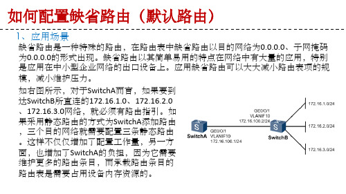
缺省路由是一种特殊的路由,在路由表中缺省路由以目的网络为0.0.0.0、子网掩码 为0.0.0.0的形式出现。缺省路由以其简单易用的特点在网络中有大量的应用,特别 是应用在中小型企业网络的出口设备上。应用缺省路由可以大大减小路由表项的规 模,减小维护压力。
如右图所示,对于SwitchA而言,如果要到 达SwitchB所直连的172.16.1.0、172.16.2.0 、172.16.3.0网络,就必须有路由指引。如 果采用静态路由的方式为SwitchA添加路由 ,三个目的网络就需要配置三条静态路由 。这样不仅仅增加了配置工作量,另一方 面,也增加了SwitchA的负担,因为它需要 维护更多的路由条目,而承载路由条目的 路由表是需要占用设备内存资源的。
静态和缺省路由配置

一、实验目的掌握路由表的概念,理解路由表的内容,理解IP路由过程,掌握静态路由和缺省路由的配置。
二、实验原理三、实验过程(1) 选择三台C2811 路由器,分别关闭电源后添加WIC-2T 模块,添加位置53为插槽0/接口适配器0(即4个小插槽中位于右下角的那个插槽)。
添加两台计算机分别连接C2811A 和C2811B 路由器的f0/1 接口,计算机IP地址与网关设置如图11-3所示。
(2) 按实验线路连接图完成各个路由器接口的IP地址设置,其中serial 接口采用默认HDLC封装即可(即不用配置封装),注意DCE接口要配置时钟频率。
测试C2811A 与192.168.10.2之间、C2811A与C2811B之间、C2811A与Internet接入路由器之间相互ping 通,测试C2811B 与192.168.30.2 之间相互ping通。
(3) 完成以上配置之后,192.168.30.2 与192.168.10.2 之间无法ping通,思考无法ping通的原因是什么。
没有配置回程静态路由。
(4)在C2811A上配置到达192.168.30.0/24的静态路由,在C2811A上配置到达Internet的缺省路由。
在C2811B上配置到达192.168.10.0/24 和Internet的缺省路由。
在Internet接入路由器上配置到达192.168.0.0/16 的静态路由。
(5) 在各台路由器上使用show ip route 查看路由表,详细理解路由表的内容。
(6) 192.168.30.2 与192.168.10.2 之间相互ping 通,192.168.30.2 与10.1.1.1 之间相互ping 通。
四、思考并回答以下问题1. 如果不在 Internet 接入路由器上配置到达 192.168.0.0/16 的静态路由,会发生什么情况?静态路由是具有单向性的,仅为数据提供下一跳的方向进行路由,不提供反向路由,会ping不通,下一跳IP地址是静态路由的根本,没有下一跳地址,那么路由就不会到达想要的网域。
华为路由器的配置(实训)

//设置缺省过滤为允许
[RouterC]acl 10
//定义访问控制列表,列表号为10
[RouterC-acl-10]rule normal deny source 10.65.1.2
//拒绝IP地址为的PC机
[RouterC-acl-10]rule normal permit source any //允许其他IP地址的访问
三、测试连通性
HostA#ping 10.65.1.2 (通) HostA#ping 10.65.1.1 (通) HostA#ping 10.68.1.1 (通) HostA#ping 10.68.1.2 (不通) HostA#ping 10.66.1.2 (不通)
[RouterA]ip route-static 10.66.0.0 255.255.0.0 10.68.1.2 [RouterB]ip route-static 10.65.0.0 255.255.0.0 10.68.1.1 HostA#ping 10.68.1.2 (通) HostA#ping 10.66.1.2 (通)
[s3026]dis curr
//显示交换机配置信息
HostA#ping 10.66.1.2 (通)
一.配置PC机的IP地址
○ HostA:Ip:: ○ HostB:Ip::
实训三、静态路由的配置
二、配置路由器 <Quidway>system-view password: [Quidway]sysname RouterA [RouterA]interface ethernet0 [RouterA-Ethernet0]ip addrress [RouterA-Ethernet0]undo shutdown [RouterA-Ethernet0]int s0 [RouterA-Serial0]ip addrress [RouterA-Serial0]undo shutdown [RouterA-Serial0]clock rate 64000 [RouterA-Serial0]quit [RouterA]ip routing [RouterA]dis curr
计算机网络实验报告——静态路由与缺省路由的使用
实验三静态路由与缺省路由的使用一、实验环境:Windows7操作系统的计算机;Boson Netsim for CCNA v6.0805交换机二、实验步骤;rt1接到pc1,rt2接到pc2,rt1到rt2选择点到点类型,rt2的serial0作为DCE端。
配置如下:(1)Router1配置:Router>enableRouter#config tEnter configuration commands, one per line. End with CNTL/Z.Router(config)#hostname router1router1(config)#ena se c1router1(config)#vty 0 4^% Invalid input detected at '^' marker.router1(config)#line vty 0 4router1(config-line)#loginrouter1(config-line)#pass c2router1(config-line)#int eth 0router1(config-if)#ip address 192.168.1.1 255.255.255.0router1(config-if)#no shut%LINK-3-UPDOWN: Interface Ethernet0, changed state to uprouter1(config-if)#int se 0router1(config-if)#ip address 10.0.0.1 255.0.0.0router1(config-if)#clock rate 64000router1(config-if)#no shut%LINK-3-UPDOWN: Interface Serial0, changed state to up%LINK-3-UPDOWN: Interface Serial0, changed state to down%LINEPROTO-5-UPDOWN: Line protocol on Interface Serial0, changed state to downrouter1(config-if)#endrouter1#copy run startDestination filename [startup-config]?Building configuration...[OK](2)Router2配置:Router>enableRouter#config tEnter configuration commands, one per line. End with CNTL/Z.Router(config)#host router2router2(config)#ena se c1router2(config)#line vty 0 4router2(config-line)#loginrouter2(config-line)#pass c2router2(config-line)#int eth 0router2(config-if)#ip address 192.168.2.1 255.255.255.0router2(config-if)#no shut%LINK-3-UPDOWN: Interface Ethernet0, changed state to uprouter2(config-if)#int se 0router2(config-if)#ip add 10.0.0.2 255.0.0.0router2(config-if)#no shut%LINK-3-UPDOWN: Interface Serial0, changed state to up%LINK-3-UPDOWN: Interface Serial0, changed state to down%LINEPROTO-5-UPDOWN: Line protocol on Interface Serial0, changed state to downrouter2(config-if)#endrouter2#copy run startDestination filename [startup-config]?Building configuration...[OK](3)PC配置:PC1 192.168.1.2 255.255.255.0 192.168.1.1PC2 192.168.2.2 255.255.255.0 192.168.1.1(4)配置,测试静态路由在Rputer1中配置:router1#ip route 192.168.2.0 255.255.255.0 10.0.0.2^% Invalid input detected at '^' marker.router1# ip router 192.168.2.0 255.255.255.0 10.0.0.2^% Invalid input detected at '^' marker.router1#config tEnter configuration commands, one per line. End with CNTL/Z.router1(config)# ip route 192.168.2.0 255.255.255.0 10.0.0.2router1(config)#endrouter1#copy run startDestination filename [startup-config]?Building configuration...[OK]router1#router1#show ip rpute^% Invalid input detected at '^' marker.router1#show ip routeCodes: C - connected, S - static, I - IGRP, R - RIP, M - mobile, B - BGP D - EIGRP, EX - EIGRP external, O - OSPF, IA - OSPF inter area E1 - OSPF external type 1, E2 - OSPF external type 2, E - EGP i - IS-IS, L1 - IS-IS level-1, L2 - IS-IS level-2, * - candidate defaultU - per-user static routeGateway of last resort is not setC 192.168.1.0 is directly connected, Ethernet0S 192.168.2.0 [1/0] via 10.0.0.2在Router2中配置:router2#router2#router2#config tEnter configuration commands, one per line. End with CNTL/Z.router2(config)#ip route 192.168.1,0 255.255.255.0 10.0.0.1% Invalid input detected at '^' marker.router2(config)#ip route 192.168.1.0 255.255.255.0 10.0.0.1router2(config)#endrouter2#copy run startDestination filename [startup-config]?Building configuration...[OK]router2#show ip rpute^% Invalid input detected at '^' marker.router2#show ip routeCodes: C - connected, S - static, I - IGRP, R - RIP, M - mobile, B - BGP D - EIGRP, EX - EIGRP external, O - OSPF, IA - OSPF inter areaE1 - OSPF external type 1, E2 - OSPF external type 2, E - EGP i - IS-IS, L1 - IS-IS level-1, L2 - IS-IS level-2, * - candidate defaultU - per-user static routeGateway of last resort is not setC 192.168.2.0 is directly connected, Ethernet0S 192.168.1.0 [1/0] via 10.0.0.1再分别选择R1,R2测试静态路由,命令如下:router1#show ip rpute^% Invalid input detected at '^' marker.router1#show ip routeCodes: C - connected, S - static, I - IGRP, R - RIP, M - mobile, B - BGPD - EIGRP, EX - EIGRP external, O - OSPF, IA - OSPF inter areaE1 - OSPF external type 1, E2 - OSPF external type 2, E - EGPi - IS-IS, L1 - IS-IS level-1, L2 - IS-IS level-2, * - candidate defaultU - per-user static routeGateway of last resort is not setC 192.168.1.0 is directly connected, Ethernet0S 192.168.2.0 [1/0] via 10.0.0.2router2#show ip routeCodes: C - connected, S - static, I - IGRP, R - RIP, M - mobile, B - BGPD - EIGRP, EX - EIGRP external, O - OSPF, IA - OSPF inter areaE1 - OSPF external type 1, E2 - OSPF external type 2, E - EGPi - IS-IS, L1 - IS-IS level-1, L2 - IS-IS level-2, * - candidate defaultU - per-user static routeGateway of last resort is not setC 192.168.2.0 is directly connected, Ethernet0S 192.168.1.0 [1/0] via 10.0.0.1(5) 配置,测试缺省路由:router2#config tEnter configuration commands, one per line. End with CNTL/Z.router2(config)#no ip route 192.168.1.0 255.255.255.0 10.0.0.1router2(config)#ip route 0.0.0.0 0.0.0.0 10.0.0.1router2(config)#endrouter2#copy run startDestination filename [startup-config]?Building configuration...[OK]三、最终配置列表:四、结果分析:配置完PC后,先测试一下:在PC1 ping Router1C:>ping 192.168.1.1Pinging 192.168.1.1 with 32 bytes of data:Reply from 192.168.1.1: bytes=32 time=60ms TTL=241Reply from 192.168.1.1: bytes=32 time=60ms TTL=241Reply from 192.168.1.1: bytes=32 time=60ms TTL=241Reply from 192.168.1.1: bytes=32 time=60ms TTL=241Reply from 192.168.1.1: bytes=32 time=60ms TTL=241Ping statistics for 192.168.1.1: Packets: Sent = 5, Received = 5, Lost = 0 (0% loss),Approximate round trip times in milli-seconds:Minimum = 50ms, Maximum = 60ms, Average = 55ms在PC2 ping Router2C:>ping 192.168.2.1Pinging 192.168.2.1 with 32 bytes of data:Reply from 192.168.2.1: bytes=32 time=60ms TTL=241Reply from 192.168.2.1: bytes=32 time=60ms TTL=241Reply from 192.168.2.1: bytes=32 time=60ms TTL=241Reply from 192.168.2.1: bytes=32 time=60ms TTL=241Reply from 192.168.2.1: bytes=32 time=60ms TTL=241Ping statistics for 192.168.2.1: Packets: Sent = 5, Received = 5, Lost= 0 (0% loss),Approximate round trip times in milli-seconds:Minimum = 50ms, Maximum = 60ms, Average = 55msC:>:>ping 192.168.2.2Pinging 192.168.2.2 with 32 bytes of data:Reply from 192.168.2.2: bytes=32 time=60ms TTL=241Reply from 192.168.2.2: bytes=32 time=60ms TTL=241Reply from 192.168.2.2: bytes=32 time=60ms TTL=241Reply from 192.168.2.2: bytes=32 time=60ms TTL=241Reply from 192.168.2.2: bytes=32 time=60ms TTL=241Ping statistics for 192.168.2.2: Packets: Sent = 5, Received = 5, Lost = 0 (0% loss),Approximate round trip times in milli-seconds:Minimum = 50ms, Maximum = 60ms, Average = 55ms配置缺省路由后:C:>ping 172.16.1.1Pinging 172.16.1.1with 32 bytes of data:Reply from 172.16.1.1: bytes=32 time=60ms TTL=241Reply from 172.16.1.1: bytes=32 time=60ms TTL=241Reply from 172.16.1.1: bytes=32 time=60ms TTL=241Reply from 172.16.1.1: bytes=32 time=60ms TTL=241Reply from 172.16.1.1: bytes=32 time=60ms TTL=241Ping statistics for 172.16.1.1: Packets: Sent = 5, Received = 5, Lost = 0 (0% loss),Approximate round trip times in milli-seconds:Minimum = 50ms, Maximum = 60ms, Average = 55ms五、实验拓扑截图:六、心得体会:通过本次实验掌握了静态路由与缺省路由的配置方法,但是对于实验中的许多命令还是不熟练,今后要多加练习。
如何配置缺省路由
如何配置缺省路由(默认路由)
1、应用场景(续)
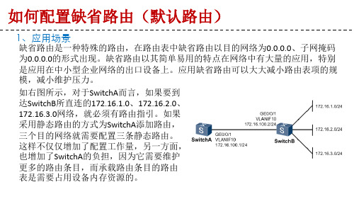
从网络设计及优化的角度,我们往往在保 证网络路由可达性的同时,尽量减少路由 器路由表的条目数量。 在右图这个场景中,由于SwitchA仅有一条 出口线路,因此我们可以在SwitchA上配置 一条缺省路由, 下一跳为SwitchB,这样 既可在保证SwitchA到SwitchB所直连的三 个网络可达的同时,路由条目达到最简。
设备上演示……
如何配置缺省路由(默认路由)
3、检查配置结果
(1)配置完成后,可以通过display ip routing-table命令检查配置是否成功 。 可以看到在设备的IP路由表中加了一条目的网段和子网掩码都是0的路由,这 条就是刚才配置的缺省路由。
如何配置缺省路由(默认路由)
1、应用场景
缺省路由是一种特殊的路由,在路由表中缺省路由以目的网络为0.0.0.0、子网掩码 为0.0.0.0的形式出现。缺省路由以其简单易用的特点在网络中有大量的应用,特别 是应用在中小型企业网络的出口设备上。应用缺省路由可以大大减小路由表项的规 模,减小维护压力。
如右图所示,对于SwitchA而言,如果要到 达SwitchB所直连的172.16.1.0、172.16.2.0、 172.16.3.0网络,就必须有路由指引。如果 采用静态路由的方式为SwitchA添加路由, 三个目的网络就需要配置三条静态路由。 这样不仅仅增加了配置工作量,另一方面, 也增加了SwitchA的负担,因为它需要维护 更多的路由条目,而承载路由条目的路由 表是需要占用设备内存资源的。
配置了缺省路由以后,对于SwitchA来说,当数据包的目的IP匹配不到明细路由的时候将会使 用缺省路由指导报文转发。可作为交换机的“最后求助对象”使用
实验3.缺省路由

实验3.缺省路由1.实验设备3台路由器、5台PC机2.实验要求与步骤A.R0路由器的端口配置R0(config)#int f0/0R0(config-if)#ip add 192.168.0.1 255.255.255.0R0(config-if)#no shu%LINK-5-CHANGED: Interface FastEthernet0/0, changed state to upR0(config-if)# R0(config-if)#int f0/1R0(config-if)#ip add 192.168.3.1 255.255.255.0R0(config-if)#no shuR0(config-if)#%LINK-5-CHANGED: Interface FastEthernet0/1, changed state to upR0(config-if)#int s0/0/0R0(config-if)#ip add 192.168.1.1 255.255.255.0R0(config-if)#clock rate 64000R0(config-if)#no shuB.R1路由器的端口配置R1(config)#int f0/0R1(config-if)#ip add 192.168.4.1 255.255.255.0R1(config-if)#exiR1(config)#R1(config)#interface FastEthernet0/0R1(config-if)#R1(config-if)#exitR1(config)#interface FastEthernet0/0R1(config-if)#int s0/0/0R1(config-if)#ip add 192.168.1.2 255.255.255.0R1(config-if)#no shu%LINK-5-CHANGED: Interface Serial0/0/0, changed state to upR1(config-if)#R1(config-if)#int s0/0/1R1(config-if)#ip add 192.168.2.1% Incomplete command.R1(config-if)#ip add 192.168.2.1 255.255.255.0R1(config-if)#no shu%LINK-5-CHANGED: Interface Serial0/0/1, changed state to downR1(config-if)#clock rate 64000R1(config-if)#exiC.R2路由器的端口配置R2(config)#int f0/0R2(config-if)#ip add 192.168.5.1 255.255.255.0R2(config-if)#no shu%LINK-5-CHANGED: Interface FastEthernet0/0, changed state to upR2(config-if)# R2(config-if)#int f0/1R2(config-if)#ip add 192.168.6.1% Incomplete command.R2(config-if)#ip add 192.168.6.1 255.255.255.0R2(config-if)#no shuR2(config-if)#%LINK-5-CHANGED: Interface FastEthernet0/1, changed state to upR2(config-if)#int s0/0/1R2(config-if)#ip add 192.168.2.2 255.255.255.0R2(config-if)#no shuD.缺省路由的配置R0(config)#ip route 0.0.0.0 0.0.0.0 192.168.1.2R1(config)#ip route 0.0.0.0 0.0.0.0 192.168.1.1R1(config)#ip route 0.0.0.0 0.0.0.0 192.168.2.2R2(config)#ip route 0.0.0.0 0.0.0.0 192.168.2.1。
cisoc 缺省路由配置

实验三缺省路由一、实验设备3台28系列型号路由器通过串口相连。
二、实验要求三台2811通过缺省路由使全网互通。
三、实验步骤R1的基本配置:R1#conf tR1#(config)# int fa0/0R1#(config-if)# ip add 192.168.0.1 255.255.255.0R1#(config-if)# exitR1#(config)# int fa0/1R1#(config-if)# ip add 192.168.3.1 255.255.255.0R1#(config-if)# exitR1#(config)# int s0/0/0R1#(config-if)# ip add 192.168.1.1 255.255.255.0R1#(config-if)# no shutR1#(config-if)# clock rate 64000R2的基本配置:R2#conf tR2(config)# int fa0/0R2(config-if)# ip add 192.168.4.1 255.255.255.0R2(config-if)# exitR2(config)# int s0/0/0R2(config-if)# ip add 192.168.1.2 255.255.255.0R2(config-if)# no shutR2(config-if)# exitR2(config)# int s0/0/0R2(config-if)# ip add 192.168.1.2 255.255.255.0R2(config-if)# no shutR2(config-if)# exitR2(config)# int s0/0/1R2(config-if)# ip add 192.168.2.1 255.255.255.0R2(config-if)# no shutR2(config-if)# clock rate 64000R3的基本配置:R3#conf tR3#(config)# int fa0/0R3#(config-if)# ip add 192.168.6.1 255.255.255.0R3#(config-if)# exitR3#(config)# int fa0/1R3#(config-if)# ip add 192.168.5.1 255.255.255.0R3#(config-if)# exitR3#(config)# int s0/0/1R3#(config-if)# ip add 192.168.2.2 255.255.255.0R3#(config-if)# no shut缺省路由配置:R1(config)# ip route 0.0.0.0 0.0.0.0 192.168.1.2 R2(config)# ip route 0.0.0.0 0.0.0.0 192.168.1.1 R2(config)# ip route 0.0.0.0 0.0.0.0 192.168.2.2 R3(config)# ip route 0.0.0.0 0.0.0.0 192.168.2.1。
实验04:静态路由、缺省路由的配制

实验四:静态路由、缺省路由的配制实验目的:三台路由连接5个网段,配置静态路由和缺省路由拓扑图:实验过程:配置路由器1Press RETURN to get started.Router> user mode模式Router>enable 进入privileged mode模式Router#configure terminal 进入globle configuration mode模式Router (config)#hostname R1 设置路由器名为R1R1 (config)#interface ethernet 0 进入端口配置模式(e0)R1 (config-if)#ip address 192.168.1.1 255.255.255.0 给e0端口配置IPR1 (config-if)#no shutdown 激活、开启此端口R1 (config-if)#interface serial 0 进入端口配置模式(s0)R1 (config-if)#ip address 10.0.0.1 255.0.0.0 给s0端口配置IPR1 (config-if)#clock rate 64000 给s0端口配置时钟(只有DCE端配)R1 (config-if)#no shutdown 激活、开启此端口R1 (config-if)#exit 退出,回到globle configuration mode模式R1(config)#ip route 0.0.0.0 0.0.0.0 10.0.0.2 添加缺省路由R1(config)#exit 退出,回到privileged mode模式R1#copy running-config startup-config 保存运行中的配置到NVRAM中(重启配置不丢失)配置路由器2Press RETURN to get started.Router> user mode模式Router>enable 进入privileged mode模式Router#configure terminal 进入globle configuration mode模式Router (config)#hostname R2 设置路由器名为R2R2 (config)#interface ethernet 0 进入端口配置模式(e0)R2 (config-if)#ip address 192.168.2.1 255.255.255.0 给e0端口配置IPR2 (config-if)#no shutdown 激活、开启此端口R2 (config-if)#interface serial 0 进入端口配置模式(s0)R2 (config-if)#ip address 172.16.0.2 255.255.0.0 给s0端口配置IPR2 (config-if)#clock rate 64000 给s0端口配置时钟(只有DCE端配)R2 (config-if)#no shutdown 激活、开启此端口R2 (config-if)#interface serial 1 进入端口配置模式(s1)R2 (config-if)#ip address 10.0.0.2 255.0.0.0 给s1端口配置IPR2 (config-if)#no shutdown 激活、开启此端口R2 (config-if)#exit 退出,回到globle configuration mode模式R2(config)#ip route 192.168.1.0 255.255.255.0 10.0.0.1 添加静态路由R2(config)#ip route 192.168.3.0 255.255.255.0 172.16.0.1 添加静态路由R2(config)#exit 退出,回到privileged mode模式R2#copy running-config startup-config 保存运行中的配置到NVRAM中(重启配置不丢失)配置路由器3Press RETURN to get started.Router> user mode模式Router>enable 进入privileged mode模式Router#configure terminal 进入globle configuration mode模式Router (config)#hostname R3 设置路由器名为R3R3 (config)#interface ethernet 0 进入端口配置模式(e0)R3 (config-if)#ip address 192.168.3.1 255.255.255.0 给e0端口配置IPR3 (config-if)#no shutdown 激活、开启此端口R3 (config-if)#interface serial 1 进入端口配置模式(s1)R3 (config-if)#ip address 172.16.0.1 255.255.0.0 给s1端口配置IPR3 (config-if)#no shutdown 激活、开启此端口R3 (config-if)#exit 退出,回到globle configuration mode模式R3(config)#ip route 0.0.0.0 0.0.0.0 172.16.0.2 添加缺省路由R3(config)#exit 退出,回到privileged mode模式R3#copy running-config startup-config 保存运行中的配置到NVRAM中(重启配置不丢失)配置PC1C:>ipconfig /ip 192.168.1.2 255.255.255.0 给PC1配置IP(在BOSON中)C:>ipconfig /dg 192.168.1.1 给PC1配置网关(在BOSON中)或:C:\>netsh interface ip set address lan static 192.168.1.2 255.255.255.0 192.168.1.1 1 给PC1配置IP、网关(DOS下)配置PC2C:>ipconfig /ip 192.168.2.2 255.255.255.0 给PC2配置IP(在BOSON中)C:>ipconfig /dg 192.168.2.1 给PC2配置网关(在BOSON中)或:C:\>netsh interface ip set address lan static 192.168.2.2 255.255.255.0 192.168.2.1 1 给PC2配置IP、网关(DOS下)配置PC3C:>ipconfig /ip 192.168.3.2 255.255.255.0 给PC3配置IP(在BOSON中)C:>ipconfig /dg 192.168.3.1 给PC3配置网关(在BOSON中)或:C:\>netsh interface ip set address lan static 192.168.3.2 255.255.255.0 192.168.3.1 1 给PC3配置IP、网关(DOS下)在PC1上操作C:\>ping 192.168.2.2 测试与PC2的连通性C:\>ping 192.168.3.2 测试与PC3的连通性在路由器2上操作R2#show ip route 显示路由表信息。
静态路由、缺省路由的配制

实验:静态路由、缺省路由的配置实验目的:三台路由连接5个网段,配置静态路由和缺省路由拓扑图:Router>enRouter#conf tRouter(config)#host R1R1 (config)#int e0 进入e0端口R1(config-if)#ip add 172.16.3.1 255.255.255.0 添加e0口的IP R1(config-if)#no shut 打开e0口R1(config-if)#exitR1(config)#int s0 进入s0端口R1(config-if)#ip add 172.16.1.1 255.255.255.0 添加s0口的IP R1(config-if)#clock rate 56000 设置时钟R1(config-if)#no shut 打开s0口R1(config-if)#exitR1(config)#ip route 0.0.0.0 0.0.0.0 172.16.1.2 添加缺省路由Router>enRouter#conf tRouter(config)#host R2R2(config)#int e0 进入e0端口R2 (config-if)#ip add172.16.4.1 255.255.255.0 添加e0口的IP R2 (config-if)#no shut 打开e0口R2 (config-if)#exitR2 (config)#int s1 进入s1端口R2 (config-if)#ip add 172.16.1.2 255.255.255.0 添加s1口的IP R2 (config-if)#no shut 打开s1口R2 (config-if)#exitR2 (config)#ip route 172.16.3.0 255.255.255.0172.16.1.1 添加静态路由R2 (config)#ip route 172.16.5.0 255.255.255.0172.16.2.2 添加静态路由Router>enRouter#conf tRouter(config)#host R3R3(config)#int e0 进入e0端口R3 (config-if)#ip add 172.16.5.1 255.255.255.0 添加e0口的IP R3 (config-if)#no shut 打开e0口R3 (config-if)#exitR3 (config)#int s1 进入s1端口R3 (config-if)#ip add172.16.2.2 255.255.255.0 添加s1口的IP R3 (config-if)#no shut 打开s1口R3 (config-if)#exitR3 (config)#ip route 0.0.0.0 0.0.0.0 172.16.2.1 添加缺省路由。
IP城域网缺省路由规划部署
IP城域网缺省路由规划部署一、背景:在典型的IP城域网中,一般仅在城域网核心出口路由器上部署BGP接收骨干网国内汇总路由甚至Internet全球路由,城域网内部其它设备都通过部署指向核心出口路由器的缺省路由(0.0.0.0/0)引导上行流量,所以城域网内部缺省路由的规划部署是城域网路由规划的重点。
本文重点讨论城域网使用动态路由协议OSPF、ISIS时缺省路由的规划。
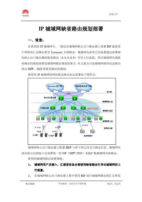
典型的IP城域网组网结构及路由协议部署如下图所示:城域网核心出口路由器上配置EBGP与骨干网之间交互路由信息,城域网内部从核心层到接入层部署统一的IGP(OSPF/ISIS)承载扩散城域网内部路由。
典型的城域网路由部署策略:1、城域网用户及接入、汇接层设备全部使用缺省路由引导出城域网的上行流量。
2、在城域网核心出口路由器上集中使用BGP进行城域网路由的汇总和发布,引导从骨干网进入城域网的下行流量。
由此可见,城域网缺省路由规划的好坏,不仅影响城域网上行流量的均衡,而且直接影响所有出城业务的可靠运行。
目前常见的城域网缺省路由部署方案如下:1、Internet骨干网(如中国电信163骨干网)通过EBGP向城域网动态下发BGP缺省路由和本运营商国内汇总路由(也可以下发整个Internet路由,目前约17万条)。
2、城域网核心出口路由器接收骨干网下发的EBGP缺省路由(缺省路由参数相同),同时使用IGP强制下发缺省路由扩散到城域网所有运行IGP的三层设备(路由器、L3交换机)。
IGP强制下发缺省路由方法的特点(以OSPF为例):使用强制方式下发缺省路由时路由器不作任何检查无条件生成type5缺省路由向整个OSPF路由域扩散;同时路由器不再学习本OSPF进程其它路由器下发的type5缺省路由。
如上图所示,城域网中所有汇接层、接入层设备到上层设备的2条上行链路等带宽,OSPF链路cost值使用参考带宽统一自动计算。
2台核心出口路由器上通过接收骨干网EBGP缺省路由引导上行流量到骨干网;由于2台核心出口路由器CR1、CR2同时以强制方式下发OSPF缺省路由,在所有的BR、AR、BAS设备上都会存在2条OSPF type5等值缺省路由引导上行流量负载分担到2台CR,整网实现了很理想的上行流量负载均衡。
静态缺省路由
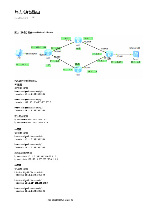
默认(缺省)路由-----Default-RoutePC 和S erver 地址配置略R1配置接口地址配置interface GigabitEthernet0/0/0ip address 12.1.1.1 255.255.255.0interface GigabitEthernet0/0/1ip address 192.168.1.254 255.255.255.0interface GigabitEthernet0/0/2ip address 14.1.1.1 255.255.255.0默认路由配置ip route-static 0.0.0.0 0.0.0.0 12.1.1.2ip route-static 0.0.0.0 0.0.0.0 14.1.1.4R2配置接口地址配置interface GigabitEthernet0/0/0ip address 12.1.1.2 255.255.255.0interface GigabitEthernet0/0/1ip address 23.1.1.2 255.255.255.0静态明细路由配置ip route-static 10.1.1.0 255.255.255.0 23.1.1.3ip route-static 192.168.1.0 255.255.255.0 12.1.1.1R3配置接口地址配置interface GigabitEthernet0/0/0ip address 23.1.1.3 255.255.255.0interface GigabitEthernet0/0/1ip address 10.1.1.254 255.255.255.0interface GigabitEthernet0/0/2ip address 34.1.1.3 255.255.255.0静态/缺省路由2018年4月20日14:23默认路由配置ip route-static 0.0.0.0 0.0.0.0 23.1.1.2ip route-static 0.0.0.0 0.0.0.0 34.1.1.4R4配置接口地址配置interface GigabitEthernet0/0/0ip address 14.1.1.4 255.255.255.0interface GigabitEthernet0/0/1ip address 34.1.1.4 255.255.255.0默认路由配置ip route-static 10.1.1.0 255.255.255.0 34.1.1.3ip route-static 192.168.1.0 255.255.255.0 14.1.1.1R1测试如下,观察报文发送情况[R1]tracert -q 10 -a 192.168.1.254 10.1.1.1浮动默认路由<R1>display ip routing-tableRoute Flags: R -relay, D -download to fib------------------------------------------------------------------------------Routing Tables: PublicDestinations : 14 Routes : 15Destination/Mask Proto Pre Cost Flags NextHop Interface0.0.0.0/0 Static 60 0 RD 12.1.1.2 GigabitEthernet0/0/0Static 60 0 RD 14.1.1.4 GigabitEthernet0/0/2ip route-static 0.0.0.0 0.0.0.0 12.1.1.2 preference 59[R1]display ip routing-tableRoute Flags: R -relay, D -download to fib------------------------------------------------------------------------------Routing Tables: PublicDestinations : 14 Routes : 14Destination/Mask Proto Pre Cost Flags NextHop Interface0.0.0.0/0 Static 59 0 RD 12.1.1.2 GigabitEtherne0/0/0 Display ip routing-table protocol static ---观察表项。
配置BGP的缺省路由

配置BGP的缺省路由一:实验目标在本实验中,配置BGP与两个Internet服务提供商(ISP)交换路由信息,如图所市视.然后配置路由过滤来控制发布的BGP路由.最后,配置缺省路由,通过使用浮动静态路由来控制哪个ISP是首选的哪个是备用的.实验设备需要以下设备来完成本实验:Cisco2600系列路由器3台串行线两条.场景国际旅行社(ITA)很大程度上依靠Internet进行销售.该公司与两个ISP签定了到Internet连接的合约以获得容错性.您需要配置运行在SanJose1边界路由器和两个ISP路由器之间的BGP.步骤一:基本配置SanJose1(config)#int s1/0SanJose1(config-if)#ip add10.0.0.2255.255.255.252SanJose1(config-if)#no shSanJose1(config)#int s1/1SanJose1(config-if)#ip add172.16.0.2255.255.255.252SanJose1(config-if)#no shSanJose1(config-if)#int lo0SanJose1(config-if)#ip add192.168.0.1255.255.255.0SanJose1(config-if)#int lo1SanJose1(config-if)#ip add192.168.1.1ISP1(config)#int s1/1ISP1(config-if)#ip add10.0.0.1255.255.255.252ISP1(config-if)#no shISP1(config-if)#int lo0ISP1(config-if)#ip add12.0.1.1255.255.255.0ISP2(config)#int s1/0ISP2(config-if)#ip add172.16.0.1255.255.255.252ISP2(config-if)#no shISP2(config-if)#int lo0ISP2(config-if)#ip add172.16.1.1255.255.255.0步骤二:配置BGPISP1(config)#router bgp200ISP1(config-router)#net12.0.1.0mask255.255.255.0ISP1(config-router)#neighbor10.0.0.2remote-as100ISP2(config)#router bgp300ISP2(config-router)#net172.16.1.0mask255.255.255.0ISP2(config-router)#neighbor172.16.0.2remote-as100SanJose1(config)#router bgp100SanJose1(config-router)#net192.168.0.0SanJose1(config-router)#net192.168.1.0SanJose1(config-router)#nei10.0.0.1remote-as200SanJose1(config-router)#neighbor172.16.0.1remote-as300这就完成了BGP的配置.用命令show ip route检查SanJose1的路由表,如下所示: SanJose1#show ip route172.16.0.0/16is variably subnetted,2subnets,2masksC172.16.0.0/30is directly connected,Serial1/1//到ISP2环回接口路由B172.16.1.0/24[20/0]via172.16.0.1,00:00:0210.0.0.0/30is subnetted,1subnetsC10.0.0.0is directly connected,Serial1/0C192.168.0.0/24is directly connected,Loopback012.0.0.0/24is subnetted,1subnetsB12.0.1.0[20/0]via10.0.0.1,00:00:02//到ISP1环回接口路由C192.168.1.0/24is directly connected,Loopback1SanJose1#ping12.0.1.1Type escape sequence to abort.Sending5,100-byte ICMP Echos to12.0.1.1,timeout is2seconds:!!!!!^-^到ISP1是通的Success rate is100percent(5/5),round-trip min/avg/max=68/301/432ms SanJose1#ping172.16.1.1Type escape sequence to abort.Sending5,100-byte ICMP Echos to172.16.1.1,timeout is2seconds:!!!!!^-^到ISP1是通的Success rate is100percent(5/5),round-trip min/avg/max=288/325/432msSanJose1#show ip bgp//查看SanJose1的BGP路由表BGP table version is5,local router ID is192.168.1.1//可以看到路由表的版本是5,本地路由器的ID是192.168.1.1(也就是它的最大环回借口的IP地址)Status codes:s suppressed,d damped,h history,*valid,>best,i-internal, r RIB-failure,S StaleOrigin codes:i-IGP,e-EGP,?-incompleteNetwork Next Hop Metric LocPrf Weight Path *>12.0.1.0/2410.0.0.100200i *>172.16.1.0/24172.16.0.100300i *>192.168.0.00.0.0.0032768i*>192.168.1.00.0.0.0032768i步骤三:优化ISP1#show ip route172.16.0.0/24is subnetted,1subnetsB172.16.1.0[20/0]via10.0.0.2,00:10:50//可以看到ISP1可以通过SanJose1到达ISP210.0.0.0/30is subnetted,1subnetsC10.0.0.0is directly connected,Serial1/1B192.168.0.0/24[20/0]via10.0.0.2,00:10:5012.0.0.0/24is subnetted,1subnetsC12.0.1.0is directly connected,Loopback0B192.168.1.0/24[20/0]via10.0.0.2,00:10:50ISP2#show ip route172.16.0.0/16is variably subnetted,2subnets,2masks C172.16.0.0/30is directly connected,Serial1/0C172.16.1.0/24is directly connected,Loopback0B192.168.0.0/24[20/0]via172.16.0.2,00:08:1412.0.0.0/24is subnetted,1subnetsB12.0.1.0[20/0]via172.16.0.2,00:08:14//可以看到ISP2可以通过SanJose1到达ISP1B192.168.1.0/24[20/0]via172.16.0.2,00:08:14ISP1通过SanJose1到达IS2,ISP2通过SanJose1到达ISP1的现象是不希望发生的,所以通过路由过滤来实现SanJose1(config)#access-list1permit192.168.0.00.0.1.255//写一条访问控制列表只允许旅行社的流量通过SanJose1(config)#router bgp100SanJose1(config-router)#neighbor10.0.0.1distribute-list1out//到BGP邻居ISP1出去的时候挂上访问控制列表,也就是拒绝了ISP2的流量SanJose1(config-router)#neighbor172.16.0.1distribute-list1out//到BGP邻居ISP2出去的时候挂上访问控制列表,也就是拒绝了ISP1的流量ISP1#show ip route10.0.0.0/30is subnetted,1subnetsC10.0.0.0is directly connected,Serial1/1B192.168.0.0/24[20/0]via10.0.0.2,00:00:0212.0.0.0/24is subnetted,1subnetsC12.0.1.0is directly connected,Loopback0B192.168.1.0/24[20/0]via10.0.0.2,00:00:02ISP2#show ip route172.16.0.0/16is variably subnetted,2subnets,2masksC172.16.0.0/30is directly connected,Serial1/0C172.16.1.0/24is directly connected,Loopback0B192.168.0.0/24[20/0]via172.16.0.2,00:21:57B192.168.1.0/24[20/0]via172.16.0.2,00:21:57看到效果了吧,ISP1里没ISP2的路由条目,ISP2里也没有ISP1的路由条目.既然和每个ISP的双向通信都已经通过BGP建立了,就需要申明首选路由和备用路由.可以用浮动静态路由或在BGP中实现这一步.解法一:浮动静态路由SanJose1#show ip route172.16.0.0/16is variably subnetted,2subnets,2masksC172.16.0.0/30is directly connected,Serial1/1B172.16.1.0/24[20/0]via172.16.0.1,00:32:1810.0.0.0/30is subnetted,1subnetsC10.0.0.0is directly connected,Serial1/0C192.168.0.0/24is directly connected,Loopback012.0.0.0/24is subnetted,1subnetsB12.0.1.0[20/0]via10.0.0.1,00:11:02C192.168.1.0/24is directly connected,Loopback1SanJose1(config)#ip route0.0.0.00.0.0.010.0.0.1210SanJose1(config)#ip route0.0.0.00.0.0.0172.16.0.1?<1-255>Distance metric for this routename Specify name of the next hoppermanent permanent routetag Set tag for this route<cr>SanJose1(config)#ip route0.0.0.00.0.0.0172.16.0.1220在看SanJose1的路由表SanJose1#show ip route172.16.0.0/16is variably subnetted,2subnets,2masksC172.16.0.0/30is directly connected,Serial1/1B172.16.1.0/24[20/0]via172.16.0.1,00:35:0610.0.0.0/30is subnetted,1subnetsC10.0.0.0is directly connected,Serial1/0C192.168.0.0/24is directly connected,Loopback012.0.0.0/24is subnetted,1subnetsB12.0.1.0[20/0]via10.0.0.1,00:13:50C192.168.1.0/24is directly connected,Loopback1S*0.0.0.0/0[210/0]via10.0.0.1//将10.0.0.1的默认路由加了进来通过在ISP1的路由上创建一个没有被通告的环回接口来测试这条缺省路由: ISP1(config)#int lo100ISP1(config-if)#ip add210.210.210.1255.255.255.0SanJose1#pingProtocol[ip]:Target IP address:210.210.210.1Repeat count[5]:Datagram siz e[100]:Timeout in seconds[2]:Extended commands[n]:ySource address or interface:192.168.1.1Type of service[0]:Set DF bit in IP header?[no]:Validate reply data?[no]:Data pattern[0xABCD]:Loose,Strict,Record,Timestamp,Verbose[none]:Sweep range of sizes[n]:Type escape sequence to abort.timeout is2seconds:210.210.210.1,timeoutSending5,100-byte ICMP Echos to210.210.210.1,Packet sent with a source address of192.168.1.1!!!!!//^-^说明默认路由确实指到了ISP1上,做到了首选路由与备用路由Success rate is100percent(5/5),round-trip min/avg/max=156/261/288ms解法二:default-networkSanJose1(config)#no ip route0.0.0.00.0.0.010.0.0.1210SanJose1(config)#no ip route0.0.0.00.0.0.0172.16.0.1220ISP1(config)#router bgp200ISP1(config-router)#net210.210.210.0ISP1(config-router)#endISP1#clear ip bgp10.0.0.2ISP1#show ip routeC210.210.210.0/24is directly connected,Loopback10010.0.0.0/30is subnetted,1subnetsC10.0.0.0is directly connected,Serial1/1B192.168.0.0/24[20/0]via10.0.0.2,00:00:2312.0.0.0/24is subnetted,1subnetsC12.0.1.0is directly connected,Loopback0B192.168.1.0/24[20/0]via10.0.0.2,00:00:23SanJose1(config)#ip default-network210.210.210.0SanJose1#show ip routeB*210.210.210.0/24[20/0]via10.0.0.1,00:01:35172.16.0.0/16is variably subnetted,2subnets,2masksC172.16.0.0/30is directly connected,Serial1/1B172.16.1.0/24[20/0]via172.16.0.1,00:48:1510.0.0.0/30is subnetted,1subnetsC10.0.0.0is directly connected,Serial1/0C192.168.0.0/24is directly connected,Loopback012.0.0.0/24is subnetted,1subnets00:01:35B12.0.1.0[20/0]via10.0.0.1,10.0.0.1,00:01:35C192.168.1.0/24is directly connected,Loopback1这样就确定了ISP1作为唯一的缺省路由.您可以通过策略路由选择操控这条路由.对此,可以通过添加一条到ISP2的主机172.16.0.1的备用路由进行修改,如下所示:SanJose1(config)#ip route0.0.0.00.0.0.0172.16.0.1220SanJose1#show ip routeB*210.210.210.0/24[20/0]via10.0.0.1,00:05:07172.16.0.0/16is variably subnetted,2subnets,2masksC172.16.0.0/30is directly connected,Serial1/1B172.16.1.0/24[20/0]via172.16.0.1,00:51:4810.0.0.0/30is subnetted,1subnetsC10.0.0.0is directly connected,Serial1/0C192.168.0.0/24is directly connected,Loopback012.0.0.0/24is subnetted,1subnets00:05:07B12.0.1.0[20/0]via10.0.0.1,10.0.0.1,00:05:07C192.168.1.0/24is directly connected,Loopback1S*0.0.0.0/0[220/0]via172.16.0.1外部网关路由协议(EBGP)所学到的路由的管理距离为20,优先于所有管理距离大于20的路由,如前面所定义的管理距离为220的缺省路由,这条路由是当网络210.210.210.0/24不可用时作为备用路由的.在SanJose1和ISP1之间的对话重新建立之后,验证这条新加入的路由是否建立了一条一致的缺省路由.注意路由表中包括两条候选的缺省路由(*),但由于它们有不同的管理距离,只有其中一条会被使用.SanJose1#show ip routeB*210.210.210.0/24[20/0]via10.0.0.1,00:12:08172.16.0.0/16is variably subnetted,2subnets,2masksC172.16.0.0/30is directly connected,Serial1/1B172.16.1.0/24[20/0]via172.16.0.1,00:58:4810.0.0.0/30is subnetted,1subnetsC10.0.0.0is directly connected,Serial1/0C192.168.0.0/24is directly connected,Loopback012.0.0.0/24is subnetted,1subnets00:12:08B12.0.1.0[20/0]via10.0.0.1,10.0.0.1,00:12:08C192.168.1.0/24is directly connected,Loopback1S*0.0.0.0/0[220/0]via172.16.0.1SanJose1#show ip route172.16.0.0/16is variably subnetted,2subnets,2masksC172.16.0.0/30is directly connected,Serial1/1B172.16.1.0/24[20/0]via172.16.0.1,00:59:2310.0.0.0/30is subnetted,1subnetsC10.0.0.0is directly connected,Serial1/0C192.168.0.0/24is directly connected,Loopback0C192.168.1.0/24is directly connected,Loopback1S*0.0.0.0/0[220/0]via172.16.0.1SanJose1#show ip routeB*210.210.210.0/24[20/0]via10.0.0.1,00:00:09172.16.0.0/16is variably subnetted,2subnets,2masksC172.16.0.0/30is directly connected,Serial1/1B172.16.1.0/24[20/0]via172.16.0.1,00:59:4910.0.0.0/30is subnetted,1subnetsC10.0.0.0is directly connected,Serial1/0C192.168.0.0/24is directly connected,Loopback012.0.0.0/24is subnetted,1subnets10.0.0.1,00:00:0900:00:09B12.0.1.0[20/0]via10.0.0.1,C192.168.1.0/24is directly connected,Loopback1S*0.0.0.0/0[220/0]via172.16.0.1正如所希望的那样,当SanJose1和ISP1之间的对话失效时,指向ISP2的路由会被添加成最后的求助网关(getway of last restore).然而,当SanJose1和ISP1之间的会话重新建立之后,缺省路由210.210.210.0会在SanJose1上重新设置为最后求助网关.。
路由器

实验九静态路由、缺省路由配置一、实验目的1、练习路由器静态路由、缺省路由配置。
2、验证静态路由、缺省路由的工作原理。
二、实验要求1.能认真独立完成实验内容。
2.实验前做好实训准备,针对实验内容,认真复习与本次实验有关的知识,完成实验内容的预习准备工作。
3.实验后做好实验总结,根据实验情况完成实验报告。
实验拓扑图静态路由、缺省路由配置二、实验步骤1、绘制实验拓扑图首先,利用Boson Network Designer 绘制实验网络拓扑图。
绘制好的拓扑图,如下图所示。
在绘图过程中请注意,按照“够用为度”的原则,这里我们可以选择805作为路由器型号。
同时,在给两台路由器间布线时要选择点到点类型。
另外,对于DCE 端可以任意选择。
不过在实验配置时对于DCE 端路由器的接口(serial 0)不要忘记配置时钟信号(这里我们选用R1的serial 0 接口作为DCE 端)。
2、配置路由器基本参数在绘制完实验拓扑图后,可以将其保存并装入Boson NetSim 中开始实验配置。
通过Boson NetSim 中的工具栏按钮“eRouters”选择“R1”并按照下面的过程进行路由器基本参数的配置:Router>enable (进入特权模式)Router#config t(进入配置模式)Router(config)#hostname R1 (设置路由器的主机名为R1)R1(config)#int eth 0 (进入路由器的以太网接口)R1(config-if)#ip add 192.168.1.1 255.255.255.0(设置以太网接口的IP地址和子网掩码)R1(config-if)#no shutdown (激活该接口)R1(config-if)#int se 0 (进入路由器的串口)R1(config-if)#ip add 10.0.0.1 255.0.0.0(设置串口的IP地址和子网掩码)R1(config-if)#clock rate 64000(设置串口的速率为64Kbps)R1(config-if)#no shutdown (激活该端口)R1(config-if)#end (从配置模式退出到特权模式)R1#copy run start (把当前的状态保存到初始状态)通过Boson NetSim 中的工具栏按钮“eRouters”选择“R2”并按照下面的过程进行路由器基本参数的配置:Router>enableRouter#conf tRouter(config)#host R2R2(config)#int eth 0R2(config-if)#ip add 192.168.2.1 255.255.255.0R2(config-if)#no shutR2(config-if)#int se 0R2(config-if)#ip add 10.0.0.2 255.0.0.0R2(config-if)#no shutR2(config-if)#endR2#copy run start3、配置PC 机基本参数通过Boson NetSim 中的工具栏按钮“eStations”选择“Host 1”并按照下面的步骤配置Host 1 的相关参数:键入“回车键”继续。
- 1、下载文档前请自行甄别文档内容的完整性,平台不提供额外的编辑、内容补充、找答案等附加服务。
- 2、"仅部分预览"的文档,不可在线预览部分如存在完整性等问题,可反馈申请退款(可完整预览的文档不适用该条件!)。
- 3、如文档侵犯您的权益,请联系客服反馈,我们会尽快为您处理(人工客服工作时间:9:00-18:30)。
《网络互联技术》课程实验指导书
实验二十一:缺省路由配置
虽然动态路由具有适应网络拓朴结构动态变化的优势,但当网络拓朴结构发生变化时,路由器需要重新生成链路数据库、重新构建网络拓朴结构、重新生成最佳路径,因此需要消耗较大的路由器系统资源。
虽然静态路由不能适应网络拓朴结构动态变化,但当通往多个目标网络具有同一个出口地址时,使用缺省静态路由就有其巨大的优势(适应网络拓朴结构的变化、减少路由器的系统资源的开销)。
路由器只有在路由表中找不到通往目的网络的路由条目时,才会启用缺省路由进行数据包的转发。
为保证启动缺省路由用户必须进行“ip classless”命令的配置。
一、实验内容
1、路由器缺省路由配置
二、实验目的
1、知道在什么情况下需要使用缺省路由,使用缺省路由有什么好处?
2、知道缺省路由在什么情况下被执行
3、掌握缺省路由的配置
三、网络拓朴
`
四、实验设备
1、四台思科Cisco 3620路由器(配置4个以太网接口)
2、四台思科Cisco 2950交换机
3、四台安装有windows 98/xp/2000操作系统的主机
4、若干交叉网线
5、思科专用控制端口连接电缆
五、实验过程(需要将相关命令写入实验报告)
1、将路由器、交换机、主机根据如上图示进行连接
2、设置主机的IP地址、子网掩码和默认网关
3、路由器A接口配置
Router> enable
Router# configure terminal
Router(config)# hostname RouterA
RouterA(config)# interface ethernet 0/0
RouterA(config-if)# ip address 192.168.1.1 255.255.255.0 RouterA(config-if)# no shutdown
RouterA(config-if)# exit
RouterA(config)# interface ethernet 0/2
RouterA(config-if)# ip address 192.168.2.1 255.255.255.0 RouterA(config-if)# no shutdown
RouterA(config-if)# exit
4、路由器B接口配置
Router> enable
Router# configure terminal
Router(config)# hostname RouterB
RouterB(config)# interface ethernet 0/0
RouterB(config-if)# ip address 192.168.3.1 255.255.255.0 RouterB(config-if)# no shutdown
RouterB(config-if)# interface ethernet 0/1
RouterB(config-if)# ip address 192.168.1.2 255.255.255.0 RouterB(config-if)# no shutdown
RouterB(config-if)# exit
RouterB(config)# interface ethernet 0/2
RouterB(config-if)# ip address 192.168.4.1 255.255.255.0 RouterB(config-if)# no shutdown
RouterB(config-if)# exit
5、路由器C接口配置
Router> enable
Router# configure terminal
Router(config)# hostname RouterC
RouterC(config)# interface ethernet 0/0
RouterC(config-if)# ip address 192.168.5.1 255.255.255.0 RouterC(config-if)# no shutdown
RouterC(config-if)# exit
RouterC(config)# interface ethernet 0/1
RouterC(config-if)# ip address 192.168.3.2 255.255.255.0 RouterC(config-if)# no shutdown
RouterC(config-if)# exit
RouterC(config-if)# ip address 192.168.6.1 255.255.255.0
RouterC(config-if)# exit
6、路由器D接口配置
Router> enable
Router# configure terminal
Router(config)# hostname RouterD
RouterD(config)# interface ethernet 0/1
RouterD(config-if)# ip address 192.168.5.2 255.255.255.0
RouterD(config-if)# no shutdown
RouterD(config-if)# exit
RouterD(config)# interface ethernet 0/2
RouterD(config-if)# ip address 192.168.8.1 255.255.255.0
RouterD(config-if)# no shutdown
RouterD(config-if)# exit
7、路由器A静态(缺省)路由配置
RouterA(config)#ip route 0.0.0.0 0.0.0.0 192.168.1.2
RouterA(config)#exit
8、路由器B静态(缺省)路由配置
RouterB(config)#ip route 192.168.2.0 255.255.255.0 192.168.1.1 RouterB(config)#ip route 0.0.0.0 0.0.0.0 192.168.3.2
RouterB(config)#exit
9、路由器C静态(缺省)路由配置
RouterC(config)#ip route 0.0.0.0 0.0.0.0 192.168.3.1
RouterC(config)#ip route 192.168.8.0 255.255.255.0 192.168.5.2 RouterC(config)#exit
10、路由器D静态(缺省)路由配置
RouterD(config)#ip route 0.0.0.0 0.0.0.0 192.168.5.1
RouterD(config)#exit
11、进行主机间ping测试
12、跟踪hosta hostd的数据包转发过程
C:> tracert 192.168.8.2
13、查看路由器A路由表信息
RouterA# show ip route
C 192.168.1.0 is directly connected, Ethernet0/0
C 192.168.2.0 is directly connected, Ethernet0/2
S* 0.0.0.0 [1/0] via 192.168.1.2
14、查看路由器B路由表信息
RouterB# show ip route
C 192.168.3.0 is directly connected, Ethernet0/0
C 192.168.1.0 is directly connected, Ethernet0/1
C 192.168.4.0 is directly connected, Ethernet0/2
S 192.168.1.0 [1/0] via 192.168.1.1
15、查看路由器C路由表信息
RouterC# show ip route
C 192.168.5.0 is directly connected, Ethernet0/0
C 192.168.3.0 is directly connected, Ethernet0/1
C 192.168.6.0 is directly connected, Ethernet0/2
S* 0.0.0.0 [1/0] via 192.168.3.1
S 192.168.8.0 [1/0] via 192.168.5.2
16、查看路由器D路由表信息
RouterD# show ip route
C 192.168.5.0 is directly connected, Ethernet0/1
C 192.168.8.0 is directly connected, Ethernet0/2
S* 0.0.0.0 [1/0] via 192.168.5.1
六、思考问题
1、在什么情况下需要使用缺省路由,使用缺省路由有什么好处?
2、缺省路由在什么情况下被执行。
七、实验报告要求:
按学院实验报告要求完成实验报告的书写。
1、实验名称的下方写明当前实验的时间(年月日)
2、在实验报告中必须回答当前实验的思考问题.。
