自动手机测试仪产品说明书
10手机综合测试仪
版 次A/0页 码2/3 1.目的
为了规范手机综合测试仪的操作,减少不必要的损失延长使用寿命及确保测量准确度。
2.范围
适用于本公司使用手机综合测试仪的操作人员。
3.示意图
4.作业程序(适用于藕合测试)
4.1 确认输出端[9]连接牢固,插上电源插头按[1]键开机.
4.2 待约4分钟后显示如[14]所示后,既可开始设置参数.
4.3 设置输出端发射信号功率,按F7键[2]两次,在数字区域[11]输入-45,然后按下确认键[12].
4.4 设置信号频段,按下F8[3],弹出一个窗口,旋转确认键[12]到所需的频段按下确认键.
4.5 按下F12[8],再按F8[3],此时进入测试选择状态.
4.6 按下显示项目按键[7],选择需要显示的参数,按下确认键出现如[14]所示的参数显示区域.
4.7 按F9[4]选择测试信道.。
电子产品测试仪器操作方法说明书

电子产品测试仪器操作方法说明书一、引言电子产品测试仪器操作方法说明书旨在帮助使用者熟悉和正确操作测试仪器,以确保电子产品的质量和性能。
本说明书详细介绍了测试仪器的功能、操作步骤和注意事项,以便用户在使用过程中能够安全、有效地进行测试。
二、仪器简介1. 仪器概述电子产品测试仪器是一款专为电子产品质量测试而设计的仪器。
它包含了电压测试、电流测试、电阻测试等多种功能,能够帮助用户准确、快速地检测电子产品的性能指标。
2. 主要特点- 多功能测试:支持电压、电流、电阻等多种测试项目,满足不同需求。
- 易操作性:采用直观的界面设计和简单的操作流程,方便用户上手使用。
- 高准确性:精密的测量技术和先进的算法保证了测试结果的准确性。
- 可靠性:稳定的测试性能和耐用的机械结构,保证了长时间的可靠使用。
三、操作步骤1. 准备工作- 确保测试仪器已经接通电源,并处于正常运行状态。
- 将待测电子产品连接到测试仪器的测试接口,并确认连接稳固可靠。
2. 功能选择- 根据待测电子产品的测试需求,选择相应的测试功能。
例如,如果需要测试电流,可以选择电流测试功能。
3. 参数设置- 根据待测电子产品的工作特性和测试要求,设置测试仪器的参数。
例如,设置测试电流的量程和采样频率。
4. 测试操作- 按下启动按钮开始测试操作。
测试仪器将自动对待测电子产品进行测试,并实时显示测试结果。
- 用户可以观察测试结果,如电流数值、电压波形等,并进行必要的记录。
5. 结果分析- 根据测试结果,分析待测电子产品的性能表现。
可以与设定的标准进行比较,以判断该产品是否符合要求。
- 如有需要,可以通过测试仪器提供的数据导出功能,将测试结果导出到计算机或其他存储设备中。
四、注意事项1. 安全操作- 在操作测试仪器前,请确保已经了解相关安全使用指南,并遵守相应的安全规定。
- 使用所需的个人防护设备,如手套、护目镜等,以防止意外伤害。
2. 仪器维护- 定期对测试仪器进行维护和清洁,确保其正常运行。
手机跌落试验机说明书

手机跌落试验机使用说明书使用仪器前,请详细阅读此说明书目录一.概述二.主要技术指标三.整机图四.使用方法提示五.维护与保养六.附件清单七.产品保修卡八.质量保证书一.概述1.手机跌落试验机是对手机(或其它小型电子产品)进行自由跌落试验的专用设备。
2.本设备主要依据IEC的标准GB/T2423.8-1995制造。
3.结构合理、独特,对不同型号手机有充分的适用性。
4.设备运行稳定,低噪音,免维护。
1外壳的耐用程度。
2内部结构抗(重)摔的性能。
3经受自由跌落的适应性。
模拟用户使用过程中,手机自由跌落动作进行试验。
人工把手机放入气动夹具内→按住复位键—气缸加持手机—按跌落键---气缸释放手机1.由电机实现丝杠升降2.跌落高度2000mm3.跌落结构保证手机随机跌落,避免非标的摩擦及碰撞运动。
二.主要技术指标1.工位数量:一工位2.操作方式:按钮3.动作执行元件:减速器电机(可选配调速电机)4.跌落高度范围:2000㎜5.实验品最大:5KG6、外形尺寸;600*600*18007.、电压:220V;功率:60W(含电机)8、重量;100kg(约)三、整机图四、使用方法提示1.插好电源220V/50Hz2.启动电源按钮,按上升/下降键调整需要跌落的高度,按停止键按复位键加持手机3.按复位键加持手机4.按跌落键跌落手机5.工作完毕后,将机台清扫干净,做好保养工作;五、维护保养1.试验机的传动机构及运动部位要定期加润滑油和定期固紧;2.非工作时应切断所有电源,移动机构上不要放置重物;3.移动机构上,要经常喷洒防锈剂;以起到保护机器表面的作用;4.做好设六附件清单机身号:出厂日期:装箱人:序号名称数量1跌落验机1台2电源线1根3说明书1份4保修卡1份5质量保证书1份6以下空白!七产品保修卡客户:发货日期:年月日品名型号机身号手机跌落试验机修理内容记录维修员签字:八质量保证书客户:保证日期:年月日至年月日品名型号机身号手机跌落试验机本保证卡保证年,保证期间内,如因质量不良,或制造之故障,可优待免费修理。
ifr1600s说明书
ifr1600s说明书
本测试仪共有3个功能菜单,在测试仪的显示屏幕上显示为:
[测试模式选择]
综合测试
容量测试
识别代码
1.综合测试:
A.测试电池种类:锂电,镍氢,镍镉。
B.测试电池电压:2.4V,3.6V,4.8V,6.0V,7.2V。
C.通用测试项目:充电测试,放电测试,内阻,电压,过流保护功能测试。
D.可选测试项目:识别代码,识别电阻。
E.标称电压为3.7V的电池等同于3.6V,识别代码的测试是针对摩托罗拉系列手机电池。
F.测试时间根据所选项目不同大约需要0.8 - 1.5秒。
2.容量测试:
A.测试电池种类:锂电,镍氢,镍镉。
B.测试电池电压:2.4V,3.6V,4.8V,6.0V,7.2V。
C.测试项目:电池总容量,平台容量,过充保护电压,过放保护电压,短路及过流保护。
D.测试时间根据电池型号及设置不同大约需要1 - 3小时。
Keysight E6640A EXM 无线测试仪 用户手册说明书
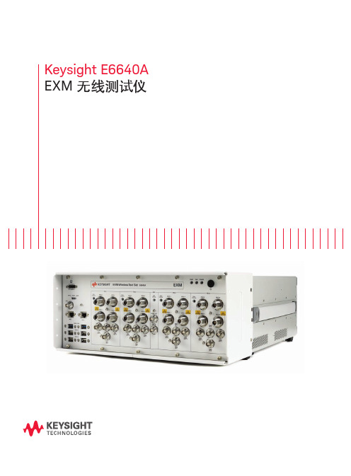
Keysight E6640A EXM 无线测试仪目录从容应对当前挑战,轻松满足未来需求 (2)根据您的生产需求进行扩展. (3)加速从新产品导入到全面量产的过程. (4)以更快的速度和更强的信心推出新产品系列. (5)为大批量制造创建灵活的系统. (7)测试场景 (10)推动芯片组获得更广泛的接受 (13)丰富经验支持 (13)产品导览 (14)相关文献 (16)从容应对当前挑战,轻松满足未来需求如今在无线行业中,智能手机和平板电脑相融合的技术数量令人难以置信。
支持蜂窝和无线连通性的多天线、多制式终端正在快速发展,满足最终用户对快速数据吞吐量、通用存取和即时共享的需要。
这给正在开发和生产最新的芯片组和用户设备(UE)的制造商带来重大挑战。
成功的制造商需要使用适当的工具,以便满足日渐严格的目标和紧凑日程。
制造商能够访问最好的资源,有助于应对技术、业务和运营风险,实行谨慎的风险管理可确保成功。
当这些风险因素得到控制时,企业就能实现几个关键目标:– 快速启动试生产– 实现并优化全面量产过程– 最大限度地降低总体测试成本– 满足预算要求– 降低损耗当前,多制式、多频段终端给制造商带来了巨大的测量挑战——找到效率更高而且效果更好的测试方法是成功的关键。
在此情况下,Keysight E6640A EXM 无线测试仪沿袭了之前测试仪中的非信令和排序功能。
根据您的生产需求进行扩展EXM 是基于 PXI 标准的平台,它的体系结构可以支持并行测试功能,并提供极高的可扩展性。
EXM 测试仪获得出色灵活性的关键是其功能丰富的发射/接收模块(TRX )。
您可以自由选择一个 TRX 模块并在今后添加多达三个 TRX 模块,您也可以升级 TRX 的频率或分析带宽,这样您能够经济有效地满足当前的生产要求,在今后生产需求扩张时保护您的投资。
2-TRX3-TRX4-TRX图 1. EXM 平台能够逐步扩大您的生产能力TRX 与 TRX 之间以及 RFIO 之间的高隔离度满足了用户对测试站支持密集度不断增加的天线和器件的需要。
掌上测量仪的操作流程与数据处理方法
掌上测量仪的操作流程与数据处理方法一、引言随着科技的不断进步,各行各业对于测量仪器的需求也越来越高。
为了方便实时测量并快速处理数据,掌上测量仪逐渐成为了许多领域中不可或缺的工具。
本文将详细介绍掌上测量仪的操作流程和数据处理方法,帮助读者更好地了解和使用这一便捷的设备。
二、掌上测量仪的操作流程1. 准备工作在使用掌上测量仪之前,我们首先需要进行一些准备工作。
包括确认测量仪是否已经充电,检查测量仪的传感器是否正确连接,以及准备工作区域并保证其安全性等。
2. 启动测量仪将掌上测量仪打开或者按下开机按钮,等待设备启动。
在启动过程中,我们可以观察掌上测量仪的菜单界面以及显示的焦点,以便了解设备的状态和功能。
3. 设置测量参数在成功启动测量仪后,我们需要根据实际需求对测量参数进行设置。
例如,在温度测量中,我们可以选择摄氏度或者华氏度,设置测量范围以及其他相关参数。
通过设备菜单界面的操作,我们可以轻松完成这些设置。
4. 进行测量一切准备就绪后,我们即可进行测量操作。
根据具体需要,我们可以通过掌上测量仪的传感器接触或者无接触测量目标物的参数。
例如,在测量体温时,我们可以将传感器放置于被测者的额头上,并等待测量结果的显示。
5. 记录数据掌上测量仪通常会自动记录测量结果,我们可以通过按键或者触摸屏幕的方式将数据保存下来。
此外,掌上测量仪还可以提供导出数据的功能,我们可以通过与电脑或者移动设备的连接,将测量结果导入到其他软件进行进一步处理。
6. 关闭测量仪在测量结束后,我们需要按照掌上测量仪的操作指导,关闭设备并妥善保管。
这样可以延长测量仪的使用寿命,并确保下次使用时可以正常运行。
三、掌上测量仪的数据处理方法1. 数据转换与标定由于不同掌上测量仪的传感器精度以及测量范围可能存在差异,所以在进行数据处理之前,我们需要对测量结果进行转换和标定。
通过与标准测量仪器进行对比和校准,可以获得更加精确和可靠的数据。
2. 数据筛选与处理在获得测量数据之后,我们还需要对其进行筛选和处理,以获得所需的结果。
自动测试仪操作说明书
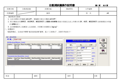
自動測試儀操作說明書第1頁共3頁設備名稱自動測試儀設備功能測試特性文件編號設備編號廠商版本A0一﹑儀器電源及連線1‧ 1. 治具及網絡分析儀接AC110V﹐電腦顯示器及主機接AC220V。
2‧ 2. 將主機接出的INPUT﹑OUTPUT﹑HULTOUT及IEEE-488GPIB排線分別接在治具上所標示的IN﹑OUT﹑HULTOUT及射頻網絡分析儀的的GPIB接口。
4‧ 3. 由空壓機提供之氣壓接入治具接頭﹐并使壓力表調節在2kg/cm2。
.二﹑軟體操作電腦開機后﹐在桌面內雙擊“濾波器測試機”圖標﹐進入“工程模式”﹐其操作界面如下﹕核准審核制作日期自動測試儀操作說明書第2頁共3頁設備名稱自動測試儀設備功能測試特性文件編號設備編號廠商版本1‧如果之前已有存檔﹐則不需輸入資料﹐點擊“載入檔案”,直接從檔案中調取資料。
2‧若沒有資料﹐則需輸入資料。
以40ST1041AX為例﹐介紹輸資料的方法如下﹕步驟一在“料號”欄中輸入40ST1041AX。
步驟二在“測試規格資料維護”欄中輸“RL”, “IL”的相關資料。
點擊“ RL”,則是選擇輸回饋損失值。
點擊“IL”﹐則是選擇輸插入損失值。
步驟三“ RL”的第一組資料如以上圖示﹐接下來輸第2組資料﹐在“SegNum”欄中輸數字2,并在“Begin Freq”欄中輸30﹐在“End Freq”欄中輸60﹐在“Begin Limit”欄中輸-12,在“End Limit”欄中輸-12﹐點擊“新增”,則第二組資料輸入完畢。
第三組資料可參照第二組的輸入方法。
步驟四“RL”的資料輸完后﹐接著輸IL的資料﹐IL與RL的資料輸入方法相同。
步驟五資料輸完后﹐點擊“儲存檔案”, 在彈出的菜單中輸入檔名40ST1041AX﹐選擇存檔類型為“.tsf”,然后確定﹐則存儲完成。
3.點擊“結束設定”﹐等5秒鐘后﹐回到測試狀態﹐其操作界面如下﹕核准審核制作日期自動測試儀操作說明書第3頁共3頁。
3G手机综合速测仪使用说明

3G 手机综合速测仪使用说明书一、 概述:3G 时代的手机更加智能化,具有更多的功能。
意味着手机电路更高的处理速度、更高的通信频率、更多的功能IC 。
手机电路中的信号包括:时钟信号、供电信号、各种控制信号、射频信号、话音信号等,通过测量信号波形、电压电流值,从而快速准确定位故障。
这也是效率最高的维修方法,但要求维修人员了解电路原理图、要求更高性能的仪器来观察电路中的信号。
传统的模拟示波器通常不能满足手机电路信号的检测,因为手机电路工作在省电的间歇方式,信号通常是跳动的。
比如主时钟信号,手机待机时26MHz 的主时钟信号0.1秒出现一次。
另外手机电路中的许多信号为高速数字信号。
传统的仪器一般检测不到这些信号。
3G 手机综合速测仪是手机维修仪器的创新产品,适用于TD-SCDMA 、WCDMA 、CDMA2000、GSM900/1800等手机维修。
仪器的主要有功能:50MHz 高速数字示波器、10MHz~3GHz 射频功率及频率检测、800MHz-2100MHz 射频信号源输出、高精度频率计、数字电压表等。
是手机维修的综合信号检测仪,本仪器的性能远优于传统仪器,几乎可以检测手机的全部信号。
为了更清楚的波形显示效果,本仪器使用3.2寸屏幕显示。
仪器主机可以通过USB 接电脑。
对信号波型进行比较、分析等处理。
1、仪器组成: a. 仪器主机1台 b. 使用说明书、使用教程光盘1 张 c. 表笔1条 d. 射频信号源线1 条 e. USB 线 1 条 f. 电源1个.2、 仪器主机:示波器输入射频输入-10100MHz 射频输入-100M 3000MHzRF 8002200MHz信号源输出-射频信号USB(供电/电脑通信)电池供电设置旋钮触摸显示屏主机前端有A、B、C输入接口,端口A和B为射频信号输入接口,C为示波器输入接口。
射频信号的频率100MHz-3GHz时使用端口A来检测、检测小于100MHz的射频信号时使用端口B。
泰勒科技Orion Star A111 pH手持检测仪说明书
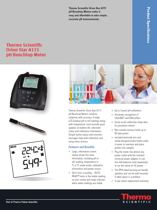
Thermo Scientific Orion Star A111pH Benchtop Meters make iteasy and affordable to take simple,accurate pH measurements.Thermo Scientific Orion Star A111pH Benchtop Meters combinesimplicity with accuracy. A largeLCD displays pH or mV readings alongwith temperature. Icons provide quickupdates on battery life, electrodestatus and calibration information.Simple button layout and onscreenmessages help with calibration andsetup menu choices.Features and Benefits• Large, informative screenclearly shows the maininformation, including pH ormV reading, temperature inºC or ºF, meter mode, calibrationinformation and power source• Don’t miss a reading – AUTO-READ™ locks in the stable readingon your screen and ready indicatoralerts when readings are stable• Up to 3 point pH calibration• Automatic recognition ofUSA/NIST and DIN buffers• Easily recall calibration slope datafor procedure checks• Non-volatile memory holds up to50 data points• Included electrode arm andnewly-designed probe holder makeit easier to maintain and placeprobes into samples• Plug the meter into almost anypower outlet with the includeduniversal power adapter, or usefour AA batteries (sold separately)to run the meter on DC power• The IP54-rated housing can handlesplashes and can be wall-mountedif table space is a problem• 3 year meter replacement warranty Thermo ScientificOrion Star A111pH Benchtop MeterNorth America 166 Cummings Center Beverly, MA 01915 USA Toll Free: 1-800-225-1480 Tel: 1-978-232-6000 *********************NetherlandsTel: (31) 033-2463887 ************************IndiaTel: (91) 22-4175-8800*************************©2011 Thermo Fisher Scientific Inc. All rights reserved. All trademarks are the property of Thermo Fisher Scientific Inc. and its subsidiaries. ROSS and the COIL tradedress are trademarks of Thermo Fisher Scientific Inc. US Patent 6,793,787.ChinaTel: (86) 21-68654588 *************************SingaporeTel: (65) 6778-6876*************************JapanTel: (81) 045-453-9175*************************AustraliaTel: (613) 9757-4300****************************Water Analysis Instruments/waterThermo Scientific Orion Star A111 pH Benchtop MeterS-STARA111-E-1011-RevBOrdering InformationFor more information, contact your local Thermo Scientific products dealer or call our customer and technical service experts at 1-800-225-1480 (for the US and Canada) or visit /water .。
AH-FG-02A 手机翻盖寿命试验机 说明书
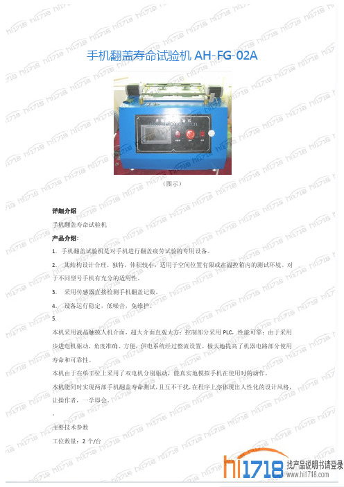
手机翻盖寿命试验机AH-FG-02A
(图示)
详细介绍
手机翻盖寿命试验机
产品介绍:
1.手机翻盖试验机是对手机进行翻盖疲劳试验的专用设备。
2.其结构设计合理、独特,体积较小,适用于空间位置有限或在温控箱内的测试环境。
对于不同型号手机有充分的适用性。
3.采用传感器直接检测手机翻盖记数。
4.设备运行稳定,低噪音,免维护。
5.
本机采用液晶触摸人机介面,超大介面直观大方;控制部分采用PLC,性能可靠;由于采用步进电机驱动,角度准确、方便,供电系统经过整流设置,极大地提高了机器电路部分使用寿命和可靠性。
本机由于在单工位上采用了双电机分别驱动,能真实地模拟手机在使用时的动作。
本机能同时实现两部手机翻盖寿命测试,且互不干扰,在程序上亦体现出人性化的设计风格,让操作者,一学即会。
主要技术参数
工位数量:2个/台
操作方式:触控屏
控制元件:进口PLC
动作执行组件:步进电机
摆臂角度范围:5~180度(自动调节)
翻盖节拍:10~60次/分钟(自动调节)
计数器:6位(内置)夹具:两套夹具
以上PDF产品资料由维库仪器仪表网()整合提供。
手机翻盖寿命测试仪操作规范
手机翻盖寿命测试仪操作规范
1.目的: 1.1、为保证手机转轴及塑壳的寿命耐久性测试正确可靠的进行,特编制本操作规范。
2.编制依据:
2.1、《手机翻盖寿命测试仪使用说明书》
3.适用范围:
3.1、适用所有手机外壳、转轴。
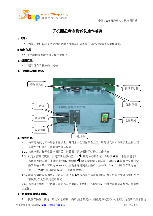
4.仪器相关部件介绍:
5.操作内容: 5.1、将所需测试之部件组装于整机上,并固定在仪器样品台上面,用绳线或胶布将手机上盖和仪器
拔动平行杆联结,将其调到最佳位置。
5.2、接通电源,打开仪器电源开关,计数器、调速器指示灯进入工作状态。
5.3、设定所需测试次数,设定方法程序:按一下
键光标移到个位,再每按▲键一下数字递增+1,当按到9时再按一下就又变为0,继续按键光标继续向前移动,同样按▲键来设定其它位
数的数值(最大可设定999999);当设定好需测试次数后,按一下 “SET ”即可保存设定值。
按一下“RST ”键可将计数器上所做次数置零。
5.4、翻盖次数计数累积达3万次后,每增加500次须做一次效果确认,察看产品转轴连接处有无异
常现象,如无异常则继续测试。
5.5、当测试完毕后,计数器自动切断马达电源,并停机工作指示灯,此时代表测试次数到,全机停
止工作。
6. 测试注意事项及要求:
6.1、仪器在保存、使用、搬运时均应善于保护,注意勿受外力碰撞造成仪器损坏,且应以适当的工具作搬运。
计数器 调速旋钮 马达开关 拔动平行杆
电源开关 样品治具台 紧固旋钮 设定按钮
6.2、使用前后应保持清洁,工作时应保持转轴部分有润滑油。
6.3、除仪器管理员和专业模具技术人员外,任何人不得拆除或设定仪器。
安捷伦8960手机测试仪器的基础介绍
Agilent 8960的构成包括移动电话特殊测试应用软件和普通测试装置硬件。安捷伦科技将继续增加新型移动电话格式并提高现存测试应用软件。
主要信息
8960系列10无线通信测试装置配置指南,p/n 5968-7880E
8960系列10多制式测试装置照片卡,p/n 5980-0286E
功能和技术指标
详细说明:无线通信测试仪8960-E5515C型号:8960/E5515C产品说明:
用于移动电话生产过程中大生产量的测试
在大批量生产移动电话的过程中,出于产量的目的,测试通过量和测试合格率是关键问题。Agilent 8960系列10无线通信测试装置为移动电话生产商提供了立即参加竞争的有利条件。对大批量、自动移动电话生产用测试系统的开发,8960系列10测试装置提供了快速、准确、可重复、多格式的能力、易编程和格式灵活的体系结构。对于手机生产商来说,这有助于降低测试成本提高产量。
选件0BK打印的手册(参考,校准和安装及维修)
深圳市凯特凯尔通讯科技有限公司专业从事二手高频通讯测试仪器的销售、出租、维修及计量业务。公司自1998年成立以来,建立了专业的信息资源及商品供应渠道,存货成色新,现货供应:公司下设维修服务中心,承接高频仪器的维修。【联系人:13266805009王生】
经营的产品品牌:
·信令协议设置:FACCH
·音频话音回声:1秒固定时延
·测量协调:脉冲类型灵活控制,ARFCN,和时隙
呼叫处理功能
MS发起、BS发起、MS释放、BS释放、小区内信道分配、小区间切换
服务小区SAACH报告:RX质量、RX电平、TX电平、定时提前量
第一邻小区SAACH报告:信道号、基站色码(BCC)、RX电平、网络色码(NCC)
VIAVI MTS-5882 移动通信技术人员全功能手持测试仪手册说明书
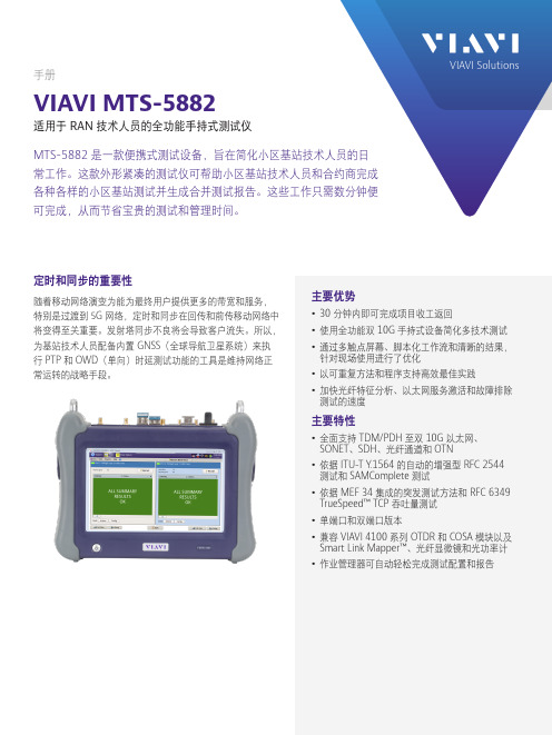
技术数据表手册VIAVI MTS-5882适用于 RAN 技术人员的全功能手持式测试仪MTS-5882 是一款便携式测试设备,旨在简化小区基站技术人员的日常工作。
这款外形紧凑的测试仪可帮助小区基站技术人员和合约商完成各种各样的小区基站测试并生成合并测试报告。
这些工作只需数分钟便可完成,从而节省宝贵的测试和管理时间。
主要优势y 30 分钟内即可完成项目收工返回y 使用全功能双 10G 手持式设备简化多技术测试 y 通过多触点屏幕、脚本化工作流和清晰的结果,针对现场使用进行了优化y 以可重复方法和程序支持高效最佳实践 y 加快光纤特征分析、以太网服务激活和故障排除测试的速度主要特性y 全面支持 TDM/PDH 至双 10G 以太网、 SONET 、SDH 、光纤通道和 OTNy 依据 ITU-T Y .1564 的自动的增强型 RFC 2544 测试和 SAMComplete 测试y 依据 MEF 34 集成的突发测试方法和 RFC 6349 TrueSpeed™ TCP 吞吐量测试 y 单端口和双端口版本y 兼容 VIAVI 4100 系列 OTDR 和 COSA 模块以及 Smart Link Mapper™、光纤显微镜和光功率计 y 作业管理器可自动轻松完成测试配置和报告定时和同步的重要性随着移动网络演变为能为最终用户提供更多的带宽和服务,特别是过渡到5G 网络,定时和同步在回传和前传移动网络中将变得至关重要。
发射塔同步不良将会导致客户流失。
所以,为基站技术人员配备内置 GNSS (全球导航卫星系统)来执行 PTP 和 OWD (单向)时延测试功能的工具是维持网络正常运转的战略手段。
© 2020 VIAVI Solutions Inc.本文档中的产品规格和描述如有更改,恕不另行通知。
5882-br-tfs-nse-zh-cn 30187321 901 0120北京 电话:+8610 6539 1166上海 电话:+8621 6859 5260上海 电话:+8621 2028 3588(仅限 TeraVM 及 TM-500 产品查询)深圳 电话:+86 755 8869 6800网站: 应用y 移动和回传(包括微波链路)特征分析,验证及故障排查y 在 10Mbps 至 10G 接口上进行聚合以太网/IP 网络测试和故障排除 y 光纤链路特征分析和故障排查y OTN 以及传统 SONET/SDH 和 TDM/PDH 网络的安装和维护 y 在无线基站处对远程射频头 (RRH) 进行测试 y 在光学链路上进行的无源互调和干扰测试 (RFoCPRI) y 下一代前传 eCPRI 支持一台测试仪可完成所有测试MTS-5882 功能非常丰富,使小区基站技术人员能够利用一台轻型手持式测试仪完成所有关键测试;其中包括: y 光纤检测:不良的光纤连接是导致网络故障的首要原因。
测试仪使用说明书

Content1.Introduction / Product Package2.Safety Measures3.Danger of electric shock and other dangers4.Intended Use5.Tester Information6.Preparation for tests6.1 Auto-power on/ switching on 6.2 Auto-power off 6.3 Self-Test7.Conducting Tests7.1 Voltage Test7.2 Single-pole phase test 7.3 Phase Rotation Test 7.4 Trip Test of RCD7.5 Continuity test (Rx) / Diode test 7.6 Resistance test 7.7 Torch Light 7.8 Data Hold 7.9 Buzzer 8.Battery Replacement 9.Technical Data 10. Cleaning and storage 11.Safety advicesReferences marked on testerW arning of a potential danger, comply with instructionmanual.☞Reference. Please pay utmost attention.C aution! Dangerous voltage. Danger of electrical shock.Equipment for working under live voltageContinuous double or reinforced insulation complies with category II DIN EN 61140.Conformity symbol, the instrument complies with the valid directives. It complies with theEMCDirective(2014/30/EU)complies with the Low Voltage Directive (2014/35/EU), StandardEN61243-3:2014T ester complieswith thestandard (2012/19/EU)WEEET he instruction manual contains information and refe-rences, necessary for safe operation and maintenance of the tester.Prior to using the tester (commissioning/ assembly)the user is kindly requested to thoroughly read the in-struction manual and comply with it in all sections. F ailure to read the tester manual or to comply with the warnings and references contained herein can result in serious bodily injury or tester damag.The respectiveaccidentprevention regulations es-tablished by the professional associations are to be strictly enforced at all times1.Introduction / Product PackageThe voltage tester 2200X is universally applicable tester and trip test of RCD.The tester is constructed according to the latest safety re-gulations and guarantee safe and reliable working.The voltage tester 2200X is characterized by the following features:•D esigned to meet international safety standards. EN61243-3:2014 and IEC61010-1• M easurement Category (CAT.) IV 600V, III 1000V• A C and DC voltage test up to 1000Vac and 1500Vdc with LCD •P olarity indication •S ingle-pole phase test • P hase rotation test • T rip Test of RCD • C ontinuity test • R esistance test • A uto-power ON / OFF • T orch light • I P64 (IEC60529)After unpacking, check that the instrument is undamaged.The product package comprises:1 pc Tester 2200X 2 pcs 4mm test tip adapters 2 pcs CAT III/ 1000V test tip cover 2 pcs batteries 1.5V, IEC LR031 pc instruction Manual7.Conducting Tests7.1 Voltage test•Connect both probes to the object under test.• The voltage is indicated by LEDs and LCD • B uzzer sounds when a threshold voltage of 50VAC or approx. 120 VDC is exceeded.•Voltage polarity is indicated in following manner.➘AC: + and – 12V LED are on ➘+DC: +12V LED is on➘-DC: -12V LED is on (and “-“ is shown on LCD)☞ W hen the L2 probe + is the positive (negative) po-tential, the Polarity indication LED indicates “+DC”(“-DC”).☞During voltage test, L or R LED may light up.☞I n case of empty batteries, the ELV LED lights up>50VAC, >120VDC7.2 Single-pole phase test☞ F unction of this test may not be fully achieved if theinsulation condition/ grounding conditions of user or of the equipment under test aren’t good enough. Ve-Single-pole phase test only, but on the voltage test.•H old the tester well in your hand. Connect the “L2 +”probe to the object under test.Single pole LED lights up and buzzer sounds when a voltage of approx. 100V AC or more exists in the object under test. (Pol≥100VAC).7.3 Phase rotation test •L LED and R LED for Phase rotation test may operate on various wiring systems, but effective testing result can be obtained only on three-phase 4-wire system.•H old the tester good in your hand and connect both probes to the object under the test.•Phase-to-phase voltage is indicated by Voltage LEDs.•• •M easurement principle: The instrument detects the phase rising order regarding the user as earth.☞ F unction of this test may not be fully achieved if theinsulation condition/ grounding conditions of user or of the equipment under test is not good enough.7.4 Trip Test of RCD☞ F or voltage tests in systems with RCD (earth leakagecircuit breakers) an RCD can be tripped with a 10mA or 30mA nominal leakage current on single phase AC 230V power system.• C onnect probes “L1” and ”L2” between L and PE of RCD protected system.• P ress simultaneously both of Trip TEST RCD Push-buttons.• The RCD should trip.7.5 Continuity test (Rx) / Diode test T he test circuit/object shall be de-energized before measurement.• C heck for the absence of voltage by conducting a two pole voltage test on the test object.I f the indication “voltage present” appears although the checked part is considered as disconnected, it is recommended to verify additional measures if the measured voltage is an interference voltage or not.4.Intended UseThe tester may be used only under the conditions and forthe purposes for which it was designed. Therefore, obser-ve in particular the safety instructions, the technical data including environmental conditions.5.Tester Information1.Test Probe, L12.Test Tip, L23.Torch Light4.Display5.Torch Light Button / Activation R-measurement6.Trip TEST RCD Pushbuttons7.Main body8.Battery door9.Technical data•V oltage range: 6…1000V AC (40…400Hz), 6…1500V DC(±)•L ED Nominal voltage: 12/24/50/120/230/400/690/ 1000V, AC (40…400Hz), DC(±)•LED tolerances according to EN61243-3•ELV indication LED >50VAC, >120VDC•Response time: < 1s at 100% of each nominal voltage •LCD Range: 6…1000VAC, 1500VDC(±)•LCD Resolution: 1V•LCD Accuracy : ±3%±3dgt (6…1000Vac/1500Vdc)•LCD Overrange indication: “OL”•Peak current: Is<3.5mA (at 1000V)•M easurement Duty: 30s ON (operation time), 240s OFF (recovery time)•Internal battery consumption: Approx. 80mA •S ingle-pole phase test voltage range: 100…1000V AC (50/60Hz)•P hase rotation test: 170…1000V phase-to-phase, AC 50/60Hz•Continuity test: Detection range 0…500kΩ + 50%•R esistance m easurement: 0-1999Ω ±(5% + 10dgt); Resolution: 1Ω•Battery: 3V (IEC LR03 1.5V x 2)•T emperature: -5…40°C operation; -20…70°C sto-rage, No condensation •Humidity: Max 85% RH •Altitude up to 2000m•Overvoltage CAT. III 1000V/ CAT. IV 600V •Standard EN61243-3:2014 and IEC61010-1•Pollution degree 2•Protection: IP 6410.Cleaning and storageT ester does not need any special maintenance if used according to user manual.Remove tester from all test points before cleaning. U se a lightly damp cloth with neutral detergent for cleaning the instrument. Do not use abrasives or sol-vents.D o not expose the instrument to direct sun light, high temperature and humidity or dewfall.R emove batteries when the instrument will not be in use for a long period.2.Safety MeasuresT he testers have been constructed and tested in ac-cordance with the safety regulations for voltage tes-ters and have left the factory in a safe and perfect condition.T he operating instructions contain information and References required for safe operation and use of the tester. Before using the tester, read the operating instructions carefully and follow them in all respects.3. D anger of electric shock and other dangersT o avoid an electric shock, observe the precautions when working with voltages exceeding 120 V (60 V)DC or 50 V (25 V) eff AC. In accordance with DIN VDE these values represent the threshold contact voltages (values in brackets refer to limited ranges,e.g. in agricultural areas).T he tester must not be used with the battery compart-ment openB efore using the tester, ensure that the test lead and device are in perfect working order. Look out e.g. for broken cables or leaking batteries.H old the tester and accessories by the designated grip areas only, the display elements must not be co-vered. Never touch the test probes.-surement ranges and in low-voltage installations up to 1000 Vac/1500Vdc.T he tester may be used only in the measuring circuit category it has been designed for.B efore and after use, always check that the tester is in perfect working order (e.g. on a known voltage source). T he tester must no longer be used if one or more functions fail or if no functionality is indicated. I t is not permitted to use the tester during rain or pre-cipitation.A perfect display is guaranteed only within a tempe-rature range of -5°C to +40°C at relative air humidity less than 85%.I f the safety of the user cannot be guaranteed, the tester must be switched off and secured against unin-tentional use.S afety is no longer guaranteed e.g. in the following cases:•obvious damage•broken housing, cracks in housing• i f the tester can no longer perform the required mea-surements/ tests•stored for too long in unfavorable conditions •damaged during transport •leaking batteriesT he tester complies with all EMC regulations. Never-theless it can happen in rare cases that electric de-or the tester is disturbed by electrical devices. Never use the tester in explosive environment Tester must be operated by trained users only O perational safety is no longer guaranteed if the tes- T he tester may be opened by an authorized service technician only.• C onnect both test probes together or press the Torch Light Pushbutton to switch ON the tester.• C onnect both test probes to the test object. For continuity (up to approx. 500kΩ) the Continuity Test LED – Rx is on and the buzzer is active.• C ontinuity test automatically switches OFF after ap-prox. 30 seconds if no continuity is detected. When tester is OFF, If continuity is detected it will be auto-matically switched on again.7.6. Resistance test Make sure that object test isn’t live.• S witch into resistance measurement by short press of torch light. Connect both test probes to the ob-ject under test. Resistance up to 2k show on LCD display. For resistance less than 30 Ohm buzzer sounds continuously to indicate low continuity.• S econd short press switches into voltage measure-ment7.7 Torch light• P ressing the torch light button will turn on the light and after approx. 30s it will turn itself off.• W hen torch light is on, pressing the torch light button for more than 6s will turn off the torch.7.8 Data HoldU nder data hold mode, The LCD screen will only show the last saved measured voltage value. No auto refresh of LCD screen reading under Data Hold mode whether the voltage tester is connected to energized or non-energized circuit. The LED voltage indicators will always show the actual voltage of the circuit un-der measurement.• A fter pressing the Torch Light push button for more than 2 seconds, the data hold function is activated and replies with a short sound. The LCD screen shows “the last measured value” and sym-bol “HOLD”. The hold function can be deactivated manually by pressing the Torch Light push button again. Function deactivation will be announced with a short sound.8.Battery ReplacementR emove the probes from any testing point, when ope -ning the Battery case. Batteries are empty when the continuity test with both test probes connected cannot be done anymore. A battery symbol in the LCD indica -tes low battery.Follow the procedure below and replace bat -teries with new ones (type IEC LR03 1.5V).• U nscrew the battery door using Philips type screwdriver.•P ull out the Battery door and replace the batteries.Insert new batteries according to the engraving on the Battery door.Control elements1.Buzzer hole for acoustic indication2.Single Pole Test ELV Warning3.Continuity Test4.5. L CD Display indication voltage,polarity and low battery 6.LED’s indicating 12V and polarity 7.Voltage IndicationAccessory1. 4 mm test Tips,2.Plug on cover (GS38)3.Protective cover6.Preparation for tests6.1 Auto-power-on/ switching on • T he tester switches on when it detects continuity, an AC or DC voltage above approx. 6V or a live phase on L2 (single pole test).•It can be switched on with the torch light button.6.2 Auto-power off• T ester is automatically powered off after 30 sec when there is no signal contacted to the probes.• The torch light switches off after approx. 30 sec.6.3 Self-Test• W hen voltage tester is off short both probes L1 and L2, hold probes shorted.• A ll LEDs, all symbols on LCD and buzzer will be on for a 2s.• S elf-test will start automatically when replacing bat-teries.I f some of LEDs is not ON, or some LCD symbols are not ON or Buzzer or Torch light is not ON, the device is not safe for use. Replace the battery and start Self-Test again. If some of these indications are not ON again, the device is not safe for use and must NOT be used.Do not use tester while Self-Test procedure is activated.11. S afety advices•D epending on the internal impedance of the voltagedetector there will be a different capability of indica-ting the presence or absence of operating voltage in case of the presence of interference voltage.•A voltage detector of relatively low internal impe-dance, compared to the reference value of 100 kΩ,will not indicate all interference voltages having an original voltage value above the ELV level. When in contact with the parts to be tested, the voltage detec-tor may discharge temporarily the interference volta-ge to a level below the ELV, but it will be back to the original value when the voltage detector is removed.•W hen the indication “voltage present” does not ap-pear, it is highly recommended installing earthing equipment before work.•A voltage detector of relatively high internal impe-dance, compared to the reference value of 100 kΩ,may not per¬mit to clearly indicate the absence of operating voltage in case of presence of interference voltage.•W hen the indication “voltage present” appears on a part that is expected to be disconnected of the instal--ther means (e.g. use of an adequate voltage detector,visual check of the disconnecting point of the electric circuit, etc.) that there is no operating voltage on the part to be tested and to conclude that the voltage indicated by the voltage detector is an interference voltage.•A voltage detector declaring two values of internal im-pedance has passed a performance test of managing interference voltages and is (within technical limits)able to distinguish operating voltage from interfe-rence voltage and has a means to directly or indirectly indicate which type of voltage is present.Voltage TesterElma 2200XManualElma Instruments A/S Ryttermarken 2DK-3520 Farum T: +45 7022 1000F: +45 7022 1001************7.9 BuzzerPress the …torchlight“ button for 5s to switch the buzzer off or on. The display indicates with “b_O” (buzzer off)and with “b_I” (buzzer on) the status of the buzzer for 2s on LCD.By default the buzzer is on (as well after battery repla-cement).•Re-assemble battery doo r.prior to measurements.。
三星(Samsung)多功能数字多功能手持测试仪说明书

Analog 31/2 and 33/4 Digit Digital Display, Pocket Size, Low Cost MultimetersModels AM8, DM7 & DM9T he ideal, compact-size metersfor basic, low-cost test andmeasurement troubleshooting.For everyday field service applications or an easy-to-use meter for home, workshop, auto, RV, boat and anything else you need to measure, one of these meters will satisfy your requirements. In addition to AC, DC and resistance measuring, each meter also includes battery testing capabilities to identify the state of charge for common 1.5V and 9 V batteries. Each meter includes Tech-Preferred™ safety test leads and the protective holster typically only found on more expensive meters, for a ready-to-use solution.DM7x2000 Count Digital Displayx Manual-Rangingx Battery Test Functionx EN61010-1 Design,x Holster and Battery IncludedQuality and features in the mostpopular, manual-ranging style describesthe DM7 meter. As an all-trade, generalpurpose meter or as the best value,homeowner’s meter, select the DM7.Precision digital read-out, AC/DC to 600volts, DC currents to 200mA, fourresistance ranges to 2MΩ, diode test andour most popular quick battery tester arefeatured in the DM7. The boot/holstermakes this meter more rugged, and itwill operate for years on its 9-volt battery. AM8x Smallest Sizex Battery Test Functionx Fused DC Current Inputx Zero Adjust for OhmsxEN61010-1 Design,2DM9x4000 Count Digital Displayx Auto-rangingx Battery Test Function with Go/NoGo LED IndicatorxEN61010-1 Design,3。
手持式测试仪使用说明

手持式测试仪使用说明一、外观介绍手持式测试仪通常由仪表主体、显示屏、操作按钮、接口等组成。
其中,仪表主体为手持式设计,便于携带和操作。
显示屏通常为彩色液晶显示屏,用于显示测试结果和参数。
操作按钮用于对测试仪进行各种设置和控制。
接口通常提供USB、RS232、LAN等多种接口,用于数据传输和设备连接等。
二、基本功能介绍1.电压测量:手持式测试仪可以对电路中的电压进行测量,并显示在屏幕上。
2.电流测量:手持式测试仪可以对电路中的电流进行测量,并显示在屏幕上。
3.频率测量:手持式测试仪可以对电路中的频率进行测量,并显示在屏幕上。
4.电阻测量:手持式测试仪可以对电路中的电阻进行测量,并显示在屏幕上。
5.温度测量:手持式测试仪可以通过连接相应的温度传感器,对环境温度进行测量,并显示在屏幕上。
6.测试仪器校准:手持式测试仪可以进行自身的校准,确保测量结果的准确性。
三、使用方法1.开机准备:插入电池或连接电源适配器,按下电源按钮打开测试仪。
2.功能选择:在测试仪的主界面上,通过方向键或触摸屏选择需要的功能,然后按下“确认”按钮进入。
3.参数设置:对于一些功能,可以通过调整参数进行设置。
根据具体情况,在屏幕上选择相应的参数设置界面,并进行调整。
4.连接设备:如果需要连接特定的设备进行测试,可以通过接口连接设备,并确保连接稳固。
5.执行测试:按下“开始测试”或类似的按钮,测试仪将自动进行测试,并在显示屏上显示结果。
6.结果分析:根据测试结果,在屏幕上进行分析和判断。
如果需要,可以通过保存数据或打印报告等方式将测试结果记录下来。
7.关机:测试完成后,按下电源按钮或选择关机选项,将测试仪关闭。
四、注意事项1.在使用手持式测试仪之前,请仔细阅读说明书,并按照要求进行操作。
2.使用前请确保测试仪的正常工作状态,如发现故障或异常,请勿使用。
3.使用时请注意安全,避免触电或其他意外伤害。
不要用湿手操作测试仪。
4.对于带电设备的测试,请确认设备断电或采取其他安全措施。
手机探测仪产品用户手册
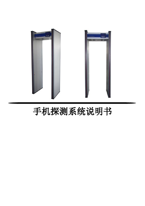
手机探测系统说明书目录第一节概述 (3)第二节系统安装 (4)2.1 探测系统组成 (4)2.2安装要求注意事项 (5)2.3安装流程 (6)第三节操作指南 (9)3.1主机箱面板介绍 (9)3.1.1主机箱面板示意图 (9)3.1.2主机箱面板介绍 (10)3.2操作功能介绍 (10)3.2.1 开机/关机功能 (10)3.2.2 灵敏度按键 (11)3.2.3 参数设置 (12)3.2.4 外设接口 (16)第四节使用规范 (17)第五节故障检测与排除 (18)第一节概述【产品介绍】本系统采用涡流检测以及电磁感应原理,集成微弱信号检测技术、精密滤波技术、有限元分析技术、梯度测量技术等技术,可以根据不同电子产品的涡流、电磁身份信息,判断出被检测人员所携带的物体,并准确分辨出是否携带手机。
HD-II型手机探测系统专门针对部队、机关、商业等领域的保密要求,在排除被检测人员日常携带物品(钥匙、皮带、眼镜、香烟、打火机等)的基础上,可以准确的检测是否携带手机(无论开关机或有无电池)并进行定位。
【产品特点】1.灵敏度高,可准确探测到手机等电子产品。
2.金属分类探测,皮带、皮鞋、钥匙不报警。
【使用场合】1.部队会议室、保密室。
2.监狱、看守所、戒毒所。
3.国家机关保密单位。
4.有保密要求的企业及单位【技术标准】a)电器参照EN60950安全标准执行。
b)辐射参照EN50081--1标准执行。
c)抗干扰参照EN50082--1标准执行。
d)《通过式金属探测门通用技术规范》国家标准GB15210-2003【技术参数】外接电源:110V~230V频率:50/60HZ功耗:60W工作环境:-20℃~45℃工作频率:根据安装环境自行调节运输全重:约100公斤;整机重量:约80公斤外形尺寸:(mm)2220(高)×850(宽)×622(深)通道尺寸:(mm)2000(高)×700(宽)×622(深)第二节系统安装2.1 探测系统组成图2-1 手机探测系统侧视图和正面视图本手机探测系统由主机箱和两块探测门板组装而成。
手机功能自动检测系统产品概念说明书V0.1

手机功能自动检测系统产品概念说明书V0.1手机功能自动检测系统产品概念说明书文件编号:0001-C17版本号:V0.1拟制人:日期:审核人:日期:批准人:日期:湖北众友科技实业股份有限公司湖北众友科技实业股份有限公司目录1产品备选概念概述 (1)1.1备选概念简介 (1)1.2备选概念比较 (2)2系统架构与标准假设 (3)2.1系统架构假设 (3)2.2产品遵循如下标准 (5)3CBB重用 (5)3.1CBB获取 (5)3.2CBB重用目标 (5)4产品版本 (7)4.1平台产品规划 (7)4.2平台产品介绍 (10)5关键技术及突破 (15)1产品备选概念概述1.1备选概念简介备选概念一:本概念为一个全功能检验站点采用一台独占的控制计算机来完成对设备和流程的控制需求。
概念一单机方案图如需要多个功能检验站点来提高效率,可通过一个长度可扩展的外部传输装置把多个功能检验站点连接起来形成一个流水线式的布局,外部传输装置通过一个可从各功能检验站点计算机获取信号的PLC来控制。
概念一多机方案备选概念二:本概念为多个以流水线布局的全功能检验站点采用一台集中控制计算机来完成协调多个功能检验站点设备和控制各功能检验站点设备内流程的控制需求。
本概念中,各功能检验站点的数目可以变化,控制计算机和PLC 始终为1台,通过改变计算机和PLC中的程序来适应功能检验站点数目不同带来的变化。
1.2备选概念比较2系统架构与标准假设2.1系统架构假设软件系统架构硬件架构2.2产品遵循如下标准1、《GB 23313-2009 工业机械电气设备电磁兼容发射限值》;2、《GB 17625.1-2003 电磁兼容限值谐波电流发射限值》(设备每相输人电流≤16A );3、《GB/T9813-2000GB/T9813 电脑噪音的国家标准》。
3CBB重用3.1CBB获取3.2CBB重用目标4产品版本4.1 平台产品规划湖北众友科技实业股份有限公司第7 页共16页注释:R001是为适应具有成熟的手机功检模式的手机。
- 1、下载文档前请自行甄别文档内容的完整性,平台不提供额外的编辑、内容补充、找答案等附加服务。
- 2、"仅部分预览"的文档,不可在线预览部分如存在完整性等问题,可反馈申请退款(可完整预览的文档不适用该条件!)。
- 3、如文档侵犯您的权益,请联系客服反馈,我们会尽快为您处理(人工客服工作时间:9:00-18:30)。
Tel: +86-755-83544900
校准标志位检测(文字识别) .............. 电池电压检测(文字识别) ................ 按键测试 ................................ RTC测试 ................................. BackLight测试 ........................... LED检测(连续) ......................... 手电筒测试(单一) ...................... 手电筒测试(抽测) ...................... 手电筒测试(全测) ...................... LCD背光测试 ............................. 音频回环测试(麦克风到听筒) ............ 音频回环测试(麦克风到喇叭) ............ Mic偏压测试 ............................. 振动测试(高-低) ....................... 振动测试(高-高) ....................... 振动测试(喇叭) ........................ 振动电流测试(高-高) ................... 振动电流测试(高-低) ................... 喇叭测试 ................................ 铃音测试 ................................ 听筒测试 ................................ 耳机偏压测试 ............................ 耳机回环测试(插入耳机按键步骤) ...... 耳机回环测试(按键步骤插入耳机) ...... 待机电流测试 ............................ 关机 .................................... 正常关机 ................................ 关机漏电流测试 .......................... 触摸屏校准 .............................. 触摸点(长按) .......................... 触摸屏滑动(水平或垂直方向) ............ 触摸屏循环滑动(水平或垂直方向) ........ 触摸屏滑动(水平方向)(预留) .......... 触摸屏滑动(垂直方向)(预留) .......... 触摸点Y方向偏移纠正 .....................
Tel: +86-755-83544900
开机铃音测试 ............................... 开机电流测试 ............................... 开机屏幕检测 ............................... 充电测试(USB电源) ........................ 充电测试(充电开关) ....................... SIM卡识别 .................................. SIM卡网络注册 .............................. 等待SIM卡网络注册 .......................... SIM卡拨号测试 ........................... 通话电流测试 ............................ T卡和铃音大小检测(声音检测) ........... T卡识别(图片检测) ..................... 蓝牙开启关闭测试(返回主界面) .......... 蓝牙开启关闭测试(不返回主界面) ........ 蓝牙开启测试(返回主界面) .............. 蓝牙开启测试(不返回主界面) ............ 开启蓝牙(弹框是否先打开蓝牙) .......... 查询蓝牙设备 ............................ WiFi开启关闭测试(返回主界面) .......... WiFi开启关闭测试(不返回主界面) ........ WiFi开启测试(返回主界面) .............. WiFi开启测试(不返回主界面) ............ 相机打开测试(图片检测) ................ 相机画面测试(黑块) .................... 相机画面测试(黑白块) .................. TV画面测试(黑白块) .................... TV声音测试(喇叭) ...................... TV声音测试(耳机) ...................... 收音机测试 .............................. USB数据测试 ............................. 多幅图片比较(同时满足) ................ 进入测试模式 ............................ 进入工程模式测试项 ...................... 软件版本测试 ............................ 校准标志位检测 ..........................
S h e n z h e n I n t e l l i w o r k Te c h n o l o g i e s C o m p a n y L i m i t e d
深 圳 市 福 田 区 滨 河 大 道 5 0 0 3 号 爱 地 大 厦 西 座 2 1 楼
21F, West Tower, AiDi Building, No.5003, Binhe Blvd. , Futian District, Shenzhen, P.R.C
5.1.37 5.1.38 5.1.39 5.1.40 5.1.41 5.1.42 5.1.43 5.1.44 5.1.45 5.1.46 5.1.47 5.1.48 5.1.49 5.1.50 5.1.51 5.1.52 5.1.53 5.1.54 5.1.55 5.1.56 5.1.57 5.1.58 5.1.59 5.1.60 5.1.61 5.1.62 5.1.63 5.1.64 5.1.65 5.1.66 5.1.67 5.1.68 5.1.69 5.1.70 5.1.71
深 圳 市 卓 讯 达 科 技 发 展 有 限 公 司
S h e n z h e n I n t e l l i w o r k Te c h n o l o g i e s C o m p a n y L i m i t e d
深 圳 市 福 田 区 滨 河 大 道 5 0 0 3 号 爱 地 大 厦 西 座 2 1 楼
2
41 42 42 42 42 43 43 43 43 44 44 44 44 45 45 45 46 46 46 46 46 47 47 47 47 47 48 48 48 48 49 49 49 49 50
Fax: +86-755-838544909
ቤተ መጻሕፍቲ ባይዱ
深 圳 市 卓 讯 达 科 技 发 展 有 限 公 司
5.1.1 开机 ....................................... 41
1
Tel: +86-755-83544900
Fax: +86-755-838544909
深 圳 市 卓 讯 达 科 技 发 展 有 限 公 司
S h e n z h e n I n t e l l i w o r k Te c h n o l o g i e s C o m p a n y L i m i t e d
深 圳 市 福 田 区 滨 河 大 道 5 0 0 3 号 爱 地 大 厦 西 座 2 1 楼
21F, West Tower, AiDi Building, No.5003, Binhe Blvd. , Futian District, Shenzhen, P.R.C
5.1.2 5.1.3 5.1.4 5.1.5 5.1.6 5.1.7 5.1.8 5.1.9 5.1.10 5.1.11 5.1.12 5.1.13 5.1.14 5.1.15 5.1.16 5.1.17 5.1.18 5.1.19 5.1.20 5.1.21 5.1.22 5.1.23 5.1.24 5.1.25 5.1.26 5.1.27 5.1.28 5.1.29 5.1.30 5.1.31 5.1.32 5.1.33 5.1.34 5.1.35 5.1.36
2.6 键盘矩阵调试..................................................................29
2.7 3 3.1 3.2 3.3 3.4 4 5 5.1